US7731735B2 - Open axle surgical implant - Google Patents
Open axle surgical implantDownload PDFInfo
- Publication number
- US7731735B2 US7731735B2US11/414,834US41483406AUS7731735B2US 7731735 B2US7731735 B2US 7731735B2US 41483406 AUS41483406 AUS 41483406AUS 7731735 B2US7731735 B2US 7731735B2
- Authority
- US
- United States
- Prior art keywords
- vertical surface
- generally vertical
- indention
- implant
- surgical implant
- Prior art date
- Legal status (The legal status is an assumption and is not a legal conclusion. Google has not performed a legal analysis and makes no representation as to the accuracy of the status listed.)
- Active, expires
Links
Images


Classifications
- A—HUMAN NECESSITIES
- A61—MEDICAL OR VETERINARY SCIENCE; HYGIENE
- A61F—FILTERS IMPLANTABLE INTO BLOOD VESSELS; PROSTHESES; DEVICES PROVIDING PATENCY TO, OR PREVENTING COLLAPSING OF, TUBULAR STRUCTURES OF THE BODY, e.g. STENTS; ORTHOPAEDIC, NURSING OR CONTRACEPTIVE DEVICES; FOMENTATION; TREATMENT OR PROTECTION OF EYES OR EARS; BANDAGES, DRESSINGS OR ABSORBENT PADS; FIRST-AID KITS
- A61F2/00—Filters implantable into blood vessels; Prostheses, i.e. artificial substitutes or replacements for parts of the body; Appliances for connecting them with the body; Devices providing patency to, or preventing collapsing of, tubular structures of the body, e.g. stents
- A61F2/02—Prostheses implantable into the body
- A61F2/30—Joints
- A61F2/44—Joints for the spine, e.g. vertebrae, spinal discs
- A—HUMAN NECESSITIES
- A61—MEDICAL OR VETERINARY SCIENCE; HYGIENE
- A61B—DIAGNOSIS; SURGERY; IDENTIFICATION
- A61B17/00—Surgical instruments, devices or methods
- A61B17/56—Surgical instruments or methods for treatment of bones or joints; Devices specially adapted therefor
- A61B17/58—Surgical instruments or methods for treatment of bones or joints; Devices specially adapted therefor for osteosynthesis, e.g. bone plates, screws or setting implements
- A61B17/68—Internal fixation devices, including fasteners and spinal fixators, even if a part thereof projects from the skin
- A61B17/70—Spinal positioners or stabilisers, e.g. stabilisers comprising fluid filler in an implant
- A61B17/7001—Screws or hooks combined with longitudinal elements which do not contact vertebrae
- A61B17/7032—Screws or hooks with U-shaped head or back through which longitudinal rods pass
- A—HUMAN NECESSITIES
- A61—MEDICAL OR VETERINARY SCIENCE; HYGIENE
- A61B—DIAGNOSIS; SURGERY; IDENTIFICATION
- A61B17/00—Surgical instruments, devices or methods
- A—HUMAN NECESSITIES
- A61—MEDICAL OR VETERINARY SCIENCE; HYGIENE
- A61B—DIAGNOSIS; SURGERY; IDENTIFICATION
- A61B17/00—Surgical instruments, devices or methods
- A61B17/56—Surgical instruments or methods for treatment of bones or joints; Devices specially adapted therefor
- A61B17/58—Surgical instruments or methods for treatment of bones or joints; Devices specially adapted therefor for osteosynthesis, e.g. bone plates, screws or setting implements
- A61B17/68—Internal fixation devices, including fasteners and spinal fixators, even if a part thereof projects from the skin
- A61B17/70—Spinal positioners or stabilisers, e.g. stabilisers comprising fluid filler in an implant
- A—HUMAN NECESSITIES
- A61—MEDICAL OR VETERINARY SCIENCE; HYGIENE
- A61B—DIAGNOSIS; SURGERY; IDENTIFICATION
- A61B17/00—Surgical instruments, devices or methods
- A61B17/56—Surgical instruments or methods for treatment of bones or joints; Devices specially adapted therefor
- A61B17/58—Surgical instruments or methods for treatment of bones or joints; Devices specially adapted therefor for osteosynthesis, e.g. bone plates, screws or setting implements
- A61B17/88—Osteosynthesis instruments; Methods or means for implanting or extracting internal or external fixation devices
- A—HUMAN NECESSITIES
- A61—MEDICAL OR VETERINARY SCIENCE; HYGIENE
- A61B—DIAGNOSIS; SURGERY; IDENTIFICATION
- A61B17/00—Surgical instruments, devices or methods
- A61B17/56—Surgical instruments or methods for treatment of bones or joints; Devices specially adapted therefor
- A61B17/58—Surgical instruments or methods for treatment of bones or joints; Devices specially adapted therefor for osteosynthesis, e.g. bone plates, screws or setting implements
- A61B17/68—Internal fixation devices, including fasteners and spinal fixators, even if a part thereof projects from the skin
- A61B17/70—Spinal positioners or stabilisers, e.g. stabilisers comprising fluid filler in an implant
- A61B17/7001—Screws or hooks combined with longitudinal elements which do not contact vertebrae
- A61B17/7035—Screws or hooks, wherein a rod-clamping part and a bone-anchoring part can pivot relative to each other
- A—HUMAN NECESSITIES
- A61—MEDICAL OR VETERINARY SCIENCE; HYGIENE
- A61B—DIAGNOSIS; SURGERY; IDENTIFICATION
- A61B17/00—Surgical instruments, devices or methods
- A61B2017/00477—Coupling
Definitions
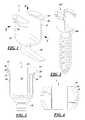
- FIGS. 10 and 11are views similar to that of FIG. 4 of other alternate preferred embodiment implants of the present invention.
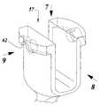
- the side face 18has a generally cylindrical recess or indention 26 penetrating the upper vertical surface 20 and the under surface 22 .
- the indention 26is torsionally engageable with an inward facing tubular protrusion 28 ( FIG. 8 ) of a surgical tool.
- a distance between the two surfaces 24is D 1 .
- the distance between the two surfaces 20is D 2 .
- the distance between the two surfaces 64is D 3 .
- the implant 57is concealed within the patient's flesh.
- a stabilization membersuch as a cable, plate or an elongated rod extends through the rod receiving area 16 .
- a surgeonuses the stabilization member to aid locating the implant 57 .
- a surgical tool(only partially shown) has the protrusions 28 set at a separation distance closely approximating D 1 . The surgeon then aligns the protrusions 28 along the lower vertical surface 24 . The surgical tool is pulled upward without separating the protrusions 28 a significant distance beyond D 1 .
- the protrusions 28are then pulled up to contact the under surface 24 .
- the protrusions 28are then turned until they seat into the indentions 62 . If the projection of the indention 62 is equal to 180° or less ( FIGS. 9A and 9B ) the protrusions 28 slides into the indention 62 without requiring an extension of the protrusions outward to a distance D 2 .
- the protrusions 28can be moved inward for content with the blind end 64 .
- the inward extension of the protrusions 28 to the blind ends 64served as a confirming indicator to the surgeon that the protrusions 28 are now ready for torsional engagement with the invention 62 . Torsional contact of the protrusions with the indentions occurs from a distance of D 2 -D 3 .
Landscapes
- Health & Medical Sciences (AREA)
- Orthopedic Medicine & Surgery (AREA)
- Life Sciences & Earth Sciences (AREA)
- Surgery (AREA)
- Neurology (AREA)
- Engineering & Computer Science (AREA)
- Biomedical Technology (AREA)
- General Health & Medical Sciences (AREA)
- Veterinary Medicine (AREA)
- Heart & Thoracic Surgery (AREA)
- Public Health (AREA)
- Animal Behavior & Ethology (AREA)
- Molecular Biology (AREA)
- Medical Informatics (AREA)
- Nuclear Medicine, Radiotherapy & Molecular Imaging (AREA)
- Cardiology (AREA)
- Oral & Maxillofacial Surgery (AREA)
- Transplantation (AREA)
- Vascular Medicine (AREA)
- Surgical Instruments (AREA)
- Prostheses (AREA)
Abstract
Description
Claims (14)
Priority Applications (7)
| Application Number | Priority Date | Filing Date | Title |
|---|---|---|---|
| US11/414,834US7731735B2 (en) | 2006-04-28 | 2006-04-28 | Open axle surgical implant |
| EP07760307AEP2015693A2 (en) | 2006-04-28 | 2007-04-09 | Open axle surgical implant |
| JP2009507880AJP2009535111A (en) | 2006-04-28 | 2007-04-09 | Open axle surgical implant |
| CNA2007800153109ACN101431955A (en) | 2006-04-28 | 2007-04-09 | Open axle surgical implant |
| KR1020087028140AKR20090008363A (en) | 2006-04-28 | 2007-04-09 | Open Axle Surgical Implants |
| PCT/US2007/066218WO2007127595A2 (en) | 2006-04-28 | 2007-04-09 | Open axle surgical implant |
| US12/768,289US8025683B2 (en) | 2006-04-28 | 2010-04-27 | Open axle surgical implant |
Applications Claiming Priority (1)
| Application Number | Priority Date | Filing Date | Title |
|---|---|---|---|
| US11/414,834US7731735B2 (en) | 2006-04-28 | 2006-04-28 | Open axle surgical implant |
Related Child Applications (1)
| Application Number | Title | Priority Date | Filing Date |
|---|---|---|---|
| US12/768,289DivisionUS8025683B2 (en) | 2006-04-28 | 2010-04-27 | Open axle surgical implant |
Publications (2)
| Publication Number | Publication Date |
|---|---|
| US20070270830A1 US20070270830A1 (en) | 2007-11-22 |
| US7731735B2true US7731735B2 (en) | 2010-06-08 |
Family
ID=38474224
Family Applications (2)
| Application Number | Title | Priority Date | Filing Date |
|---|---|---|---|
| US11/414,834Active2028-08-05US7731735B2 (en) | 2006-04-28 | 2006-04-28 | Open axle surgical implant |
| US12/768,289ActiveUS8025683B2 (en) | 2006-04-28 | 2010-04-27 | Open axle surgical implant |
Family Applications After (1)
| Application Number | Title | Priority Date | Filing Date |
|---|---|---|---|
| US12/768,289ActiveUS8025683B2 (en) | 2006-04-28 | 2010-04-27 | Open axle surgical implant |
Country Status (6)
| Country | Link |
|---|---|
| US (2) | US7731735B2 (en) |
| EP (1) | EP2015693A2 (en) |
| JP (1) | JP2009535111A (en) |
| KR (1) | KR20090008363A (en) |
| CN (1) | CN101431955A (en) |
| WO (1) | WO2007127595A2 (en) |
Cited By (2)
| Publication number | Priority date | Publication date | Assignee | Title |
|---|---|---|---|---|
| US9101426B2 (en) | 2012-10-11 | 2015-08-11 | Stryker Trauma Sa | Cable plug |
| US10499968B2 (en) | 2014-08-08 | 2019-12-10 | Stryker European Holdings I, Llc | Cable plugs for bone plates |
Families Citing this family (90)
| Publication number | Priority date | Publication date | Assignee | Title |
|---|---|---|---|---|
| US7833250B2 (en) | 2004-11-10 | 2010-11-16 | Jackson Roger P | Polyaxial bone screw with helically wound capture connection |
| US10258382B2 (en) | 2007-01-18 | 2019-04-16 | Roger P. Jackson | Rod-cord dynamic connection assemblies with slidable bone anchor attachment members along the cord |
| US10729469B2 (en) | 2006-01-09 | 2020-08-04 | Roger P. Jackson | Flexible spinal stabilization assembly with spacer having off-axis core member |
| US8353932B2 (en) | 2005-09-30 | 2013-01-15 | Jackson Roger P | Polyaxial bone anchor assembly with one-piece closure, pressure insert and plastic elongate member |
| US8292926B2 (en) | 2005-09-30 | 2012-10-23 | Jackson Roger P | Dynamic stabilization connecting member with elastic core and outer sleeve |
| US7862587B2 (en) | 2004-02-27 | 2011-01-04 | Jackson Roger P | Dynamic stabilization assemblies, tool set and method |
| US8876868B2 (en) | 2002-09-06 | 2014-11-04 | Roger P. Jackson | Helical guide and advancement flange with radially loaded lip |
| WO2006052796A2 (en) | 2004-11-10 | 2006-05-18 | Jackson Roger P | Helical guide and advancement flange with break-off extensions |
| US7621918B2 (en) | 2004-11-23 | 2009-11-24 | Jackson Roger P | Spinal fixation tool set and method |
| US6716214B1 (en) | 2003-06-18 | 2004-04-06 | Roger P. Jackson | Polyaxial bone screw with spline capture connection |
| US7377923B2 (en) | 2003-05-22 | 2008-05-27 | Alphatec Spine, Inc. | Variable angle spinal screw assembly |
| US8377102B2 (en) | 2003-06-18 | 2013-02-19 | Roger P. Jackson | Polyaxial bone anchor with spline capture connection and lower pressure insert |
| US7776067B2 (en) | 2005-05-27 | 2010-08-17 | Jackson Roger P | Polyaxial bone screw with shank articulation pressure insert and method |
| US7766915B2 (en) | 2004-02-27 | 2010-08-03 | Jackson Roger P | Dynamic fixation assemblies with inner core and outer coil-like member |
| US8926670B2 (en) | 2003-06-18 | 2015-01-06 | Roger P. Jackson | Polyaxial bone screw assembly |
| US8366753B2 (en) | 2003-06-18 | 2013-02-05 | Jackson Roger P | Polyaxial bone screw assembly with fixed retaining structure |
| US8137386B2 (en) | 2003-08-28 | 2012-03-20 | Jackson Roger P | Polyaxial bone screw apparatus |
| US8398682B2 (en) | 2003-06-18 | 2013-03-19 | Roger P. Jackson | Polyaxial bone screw assembly |
| US7967850B2 (en) | 2003-06-18 | 2011-06-28 | Jackson Roger P | Polyaxial bone anchor with helical capture connection, insert and dual locking assembly |
| US11419642B2 (en) | 2003-12-16 | 2022-08-23 | Medos International Sarl | Percutaneous access devices and bone anchor assemblies |
| US7527638B2 (en) | 2003-12-16 | 2009-05-05 | Depuy Spine, Inc. | Methods and devices for minimally invasive spinal fixation element placement |
| US7179261B2 (en) | 2003-12-16 | 2007-02-20 | Depuy Spine, Inc. | Percutaneous access devices and bone anchor assemblies |
| US8152810B2 (en) | 2004-11-23 | 2012-04-10 | Jackson Roger P | Spinal fixation tool set and method |
| US7160300B2 (en) | 2004-02-27 | 2007-01-09 | Jackson Roger P | Orthopedic implant rod reduction tool set and method |
| JP2007525274A (en) | 2004-02-27 | 2007-09-06 | ロジャー・ピー・ジャクソン | Orthopedic implant rod reduction instrument set and method |
| US11241261B2 (en) | 2005-09-30 | 2022-02-08 | Roger P Jackson | Apparatus and method for soft spinal stabilization using a tensionable cord and releasable end structure |
| US7651502B2 (en) | 2004-09-24 | 2010-01-26 | Jackson Roger P | Spinal fixation tool set and method for rod reduction and fastener insertion |
| US8926672B2 (en) | 2004-11-10 | 2015-01-06 | Roger P. Jackson | Splay control closure for open bone anchor |
| US9980753B2 (en) | 2009-06-15 | 2018-05-29 | Roger P Jackson | pivotal anchor with snap-in-place insert having rotation blocking extensions |
| US8444681B2 (en) | 2009-06-15 | 2013-05-21 | Roger P. Jackson | Polyaxial bone anchor with pop-on shank, friction fit retainer and winged insert |
| US8308782B2 (en) | 2004-11-23 | 2012-11-13 | Jackson Roger P | Bone anchors with longitudinal connecting member engaging inserts and closures for fixation and optional angulation |
| US9216041B2 (en) | 2009-06-15 | 2015-12-22 | Roger P. Jackson | Spinal connecting members with tensioned cords and rigid sleeves for engaging compression inserts |
| US9168069B2 (en) | 2009-06-15 | 2015-10-27 | Roger P. Jackson | Polyaxial bone anchor with pop-on shank and winged insert with lower skirt for engaging a friction fit retainer |
| WO2006057837A1 (en) | 2004-11-23 | 2006-06-01 | Jackson Roger P | Spinal fixation tool attachment structure |
| US10076361B2 (en) | 2005-02-22 | 2018-09-18 | Roger P. Jackson | Polyaxial bone screw with spherical capture, compression and alignment and retention structures |
| US7901437B2 (en) | 2007-01-26 | 2011-03-08 | Jackson Roger P | Dynamic stabilization member with molded connection |
| US8105368B2 (en) | 2005-09-30 | 2012-01-31 | Jackson Roger P | Dynamic stabilization connecting member with slitted core and outer sleeve |
| CA2670988C (en) | 2006-12-08 | 2014-03-25 | Roger P. Jackson | Tool system for dynamic spinal implants |
| US8366745B2 (en) | 2007-05-01 | 2013-02-05 | Jackson Roger P | Dynamic stabilization assembly having pre-compressed spacers with differential displacements |
| US8475498B2 (en) | 2007-01-18 | 2013-07-02 | Roger P. Jackson | Dynamic stabilization connecting member with cord connection |
| US10792074B2 (en) | 2007-01-22 | 2020-10-06 | Roger P. Jackson | Pivotal bone anchor assemly with twist-in-place friction fit insert |
| US10383660B2 (en) | 2007-05-01 | 2019-08-20 | Roger P. Jackson | Soft stabilization assemblies with pretensioned cords |
| US8979904B2 (en) | 2007-05-01 | 2015-03-17 | Roger P Jackson | Connecting member with tensioned cord, low profile rigid sleeve and spacer with torsion control |
| US9204908B2 (en)* | 2007-07-26 | 2015-12-08 | Dynamic Spine, Llc | Segmental orthopedic device for spinal elongation and for treatment of scoliosis |
| US8790380B2 (en) | 2007-07-26 | 2014-07-29 | Dynamic Spine, Llc | Segmental orthopaedic device for spinal elongation and for treatment of scoliosis |
| AU2010260521C1 (en) | 2008-08-01 | 2013-08-01 | Roger P. Jackson | Longitudinal connecting member with sleeved tensioned cords |
| US9005260B2 (en)* | 2009-01-15 | 2015-04-14 | Aesculap Implant Systems, Llc | Receiver body for spinal fixation system |
| US9668771B2 (en) | 2009-06-15 | 2017-06-06 | Roger P Jackson | Soft stabilization assemblies with off-set connector |
| US8998959B2 (en) | 2009-06-15 | 2015-04-07 | Roger P Jackson | Polyaxial bone anchors with pop-on shank, fully constrained friction fit retainer and lock and release insert |
| US11229457B2 (en) | 2009-06-15 | 2022-01-25 | Roger P. Jackson | Pivotal bone anchor assembly with insert tool deployment |
| CN103826560A (en) | 2009-06-15 | 2014-05-28 | 罗杰.P.杰克逊 | Polyaxial Bone Anchor with Socket Stem and Winged Inserts with Friction Fit Compression Collars |
| EP2485654B1 (en) | 2009-10-05 | 2021-05-05 | Jackson P. Roger | Polyaxial bone anchor with non-pivotable retainer and pop-on shank, some with friction fit |
| US12383311B2 (en) | 2010-05-14 | 2025-08-12 | Roger P. Jackson | Pivotal bone anchor assembly and method for use thereof |
| AU2011264818B2 (en) | 2010-06-10 | 2015-06-18 | Globus Medical, Inc. | Low-profile, uniplanar bone screw |
| AU2011299558A1 (en) | 2010-09-08 | 2013-05-02 | Roger P. Jackson | Dynamic stabilization members with elastic and inelastic sections |
| AU2011324058A1 (en) | 2010-11-02 | 2013-06-20 | Roger P. Jackson | Polyaxial bone anchor with pop-on shank and pivotable retainer |
| EP2471476A1 (en)* | 2010-11-10 | 2012-07-04 | Zimmer Spine | Bone anchor |
| JP5865479B2 (en) | 2011-03-24 | 2016-02-17 | ロジャー・ピー・ジャクソン | Multiaxial bone anchor with compound joint and pop-mounted shank |
| US8911479B2 (en) | 2012-01-10 | 2014-12-16 | Roger P. Jackson | Multi-start closures for open implants |
| US9283001B2 (en)* | 2012-01-18 | 2016-03-15 | Globus Medical, Inc. | Systems for spinal stabilization |
| IL221634A0 (en) | 2012-08-26 | 2012-12-31 | Medimop Medical Projects Ltd | Universal drug vial adapter |
| US8911478B2 (en) | 2012-11-21 | 2014-12-16 | Roger P. Jackson | Splay control closure for open bone anchor |
| US10058354B2 (en) | 2013-01-28 | 2018-08-28 | Roger P. Jackson | Pivotal bone anchor assembly with frictional shank head seating surfaces |
| US8852239B2 (en) | 2013-02-15 | 2014-10-07 | Roger P Jackson | Sagittal angle screw with integral shank and receiver |
| DE212014000169U1 (en) | 2013-08-07 | 2016-03-14 | Medimop Medical Projects Ltd. | Fluid transfer devices for use with infusion fluid containers |
| US9566092B2 (en) | 2013-10-29 | 2017-02-14 | Roger P. Jackson | Cervical bone anchor with collet retainer and outer locking sleeve |
| US9717533B2 (en) | 2013-12-12 | 2017-08-01 | Roger P. Jackson | Bone anchor closure pivot-splay control flange form guide and advancement structure |
| US9451993B2 (en) | 2014-01-09 | 2016-09-27 | Roger P. Jackson | Bi-radial pop-on cervical bone anchor |
| US9597119B2 (en) | 2014-06-04 | 2017-03-21 | Roger P. Jackson | Polyaxial bone anchor with polymer sleeve |
| US10064658B2 (en) | 2014-06-04 | 2018-09-04 | Roger P. Jackson | Polyaxial bone anchor with insert guides |
| JP6358724B2 (en) | 2015-01-05 | 2018-07-18 | ウエスト・ファーマ.サービシーズ・イスラエル,リミテッド | Dual vial adapter assembly with easy removable pill adapter to ensure accurate use |
| WO2017009822A1 (en) | 2015-07-16 | 2017-01-19 | Medimop Medical Projects Ltd | Liquid drug transfer devices for secure telescopic snap fit on injection vials |
| CN115721558A (en) | 2015-11-25 | 2023-03-03 | 西部制药服务以色列有限公司 | Dual vial adapter assembly comprising a drug vial adapter having a self-sealing inlet valve |
| IL245800A0 (en) | 2016-05-24 | 2016-08-31 | West Pharma Services Il Ltd | Dual vial adapter assemblages including identical twin vial adapters |
| IL245803A0 (en) | 2016-05-24 | 2016-08-31 | West Pharma Services Il Ltd | Dual vial adapter assemblages including vented drug vial adapter and vented liquid vial adapter |
| IL246073A0 (en) | 2016-06-06 | 2016-08-31 | West Pharma Services Il Ltd | Fluid transfer devices for use with drug pump cartridge having slidable driving plunger |
| IL247376A0 (en) | 2016-08-21 | 2016-12-29 | Medimop Medical Projects Ltd | Syringe assembly |
| IL249408A0 (en) | 2016-12-06 | 2017-03-30 | Medimop Medical Projects Ltd | Liquid transfer device for use with infusion liquid container and pincers-like hand tool for use therewith for releasing intact drug vial therefrom |
| IL251458A0 (en) | 2017-03-29 | 2017-06-29 | Medimop Medical Projects Ltd | User actuated liquid drug transfer devices for use in ready-to-use (rtu) liquid drug transfer assemblages |
| EP3441028B1 (en) | 2017-08-08 | 2021-10-06 | Biedermann Technologies GmbH & Co. KG | Receiving part and instrument for holding the receiving part |
| IL254802A0 (en) | 2017-09-29 | 2017-12-31 | Medimop Medical Projects Ltd | Dual vial adapter assemblages with twin vented female vial adapters |
| JP1630477S (en) | 2018-07-06 | 2019-05-07 | ||
| CN109009385A (en)* | 2018-08-12 | 2018-12-18 | 苏州爱得科技发展股份有限公司 | A kind of dynamic state screw |
| USD923812S1 (en) | 2019-01-16 | 2021-06-29 | West Pharma. Services IL, Ltd. | Medication mixing apparatus |
| JP1648075S (en) | 2019-01-17 | 2019-12-16 | ||
| JP7209849B2 (en) | 2019-01-18 | 2023-01-20 | ウェスト・ファーマ・サービシーズ・アイエル・リミテッド | Liquid transfer device for use with IV bottles |
| US11918542B2 (en) | 2019-01-31 | 2024-03-05 | West Pharma. Services IL, Ltd. | Liquid transfer device |
| JP7284289B2 (en) | 2019-04-09 | 2023-05-30 | ウェスト ファーマ サービシーズ イスラエル リミテッド | Infusion device with integrated syringe |
| KR20240122586A (en) | 2019-04-30 | 2024-08-12 | 웨스트 파마. 서비시즈 일, 리미티드 | Liquid transfer device with dual lumen iv spike |
| USD956958S1 (en) | 2020-07-13 | 2022-07-05 | West Pharma. Services IL, Ltd. | Liquid transfer device |
Citations (29)
| Publication number | Priority date | Publication date | Assignee | Title |
|---|---|---|---|---|
| US4050464A (en) | 1975-04-28 | 1977-09-27 | Downs Surgical Limited | Surgical cable tensioning instrument |
| US4411259A (en) | 1980-02-04 | 1983-10-25 | Drummond Denis S | Apparatus for engaging a hook assembly to a spinal column |
| US5020519A (en) | 1990-12-07 | 1991-06-04 | Zimmer, Inc. | Sagittal approximator |
| US5281222A (en) | 1992-06-30 | 1994-01-25 | Zimmer, Inc. | Spinal implant system |
| US5380326A (en) | 1993-11-12 | 1995-01-10 | Lin; Chih-I | Clamping device for vertebral locking rod |
| US5562663A (en) | 1995-06-07 | 1996-10-08 | Danek Medical, Inc. | Implant interconnection mechanism |
| US5616143A (en) | 1995-02-06 | 1997-04-01 | Schlapfer; Johannes F. | Surgical forceps |
| US5630817A (en) | 1992-11-18 | 1997-05-20 | Eurosurgical | Rod attachment device for rachidian orthopaedy |
| US5810878A (en) | 1997-02-12 | 1998-09-22 | Sdgi Holdings, Inc. | Rod introducer forceps |
| US5910141A (en) | 1997-02-12 | 1999-06-08 | Sdgi Holdings, Inc. | Rod introduction apparatus |
| US6027533A (en) | 1995-04-10 | 2000-02-22 | Olerud; Sven | Device for fixating and adjusting the positions of vertebrae in vertebral surgical operations |
| US6110172A (en) | 1998-07-31 | 2000-08-29 | Jackson; Roger P. | Closure system for open ended osteosynthesis apparatus |
| US6183472B1 (en) | 1998-04-09 | 2001-02-06 | Howmedica Gmbh | Pedicle screw and an assembly aid therefor |
| EP1190678A2 (en) | 2000-09-22 | 2002-03-27 | DePuy Acromed, Inc. | Lock cap anchor assembly for orthopaedic fixation |
| US6458132B2 (en) | 2000-03-15 | 2002-10-01 | Gil-Woon Choi | Spine supporting system |
| US6524315B1 (en) | 2000-08-08 | 2003-02-25 | Depuy Acromed, Inc. | Orthopaedic rod/plate locking mechanism |
| US20030130659A1 (en) | 2002-01-10 | 2003-07-10 | Haider Thomas T. | Orthopedic hook system |
| US6595992B1 (en) | 1996-10-24 | 2003-07-22 | Spinal Concepts, Inc. | Method and apparatus for spinal fixation |
| US20030199872A1 (en) | 2002-04-17 | 2003-10-23 | Stryker Spine | Rod persuader |
| US6656179B1 (en) | 1999-10-18 | 2003-12-02 | Bernd Schaefer | Bone plate |
| US20040143265A1 (en)* | 2002-10-30 | 2004-07-22 | Landry Michael E. | Spinal stabilization systems and methods using minimally invasive surgical procedures |
| US6783526B1 (en) | 1997-05-15 | 2004-08-31 | Howmedica Osteonics Corp. | Transverse rod connector clip |
| US6790209B2 (en) | 2001-07-03 | 2004-09-14 | Sdgi Holdings, Inc. | Rod reducer instruments and methods |
| EP1457161A1 (en) | 2003-03-11 | 2004-09-15 | BIEDERMANN MOTECH GmbH | Fixation device for use in spinal or bone surgery and method of its manufacture |
| US20040260285A1 (en) | 2003-06-17 | 2004-12-23 | Eurosurgical Sa | Pedicular hooks for rachidian anchoring device |
| WO2005006948A2 (en) | 2003-07-03 | 2005-01-27 | Hfsc Company | Top loading spinal fixation device and instruments for loading and handling the same |
| US20050149053A1 (en) | 2003-12-17 | 2005-07-07 | Varieur Michael S. | Instruments and methods for bone anchor engagement and spinal rod reduction |
| US20050154389A1 (en) | 2003-12-16 | 2005-07-14 | Depuy Spine, Inc. | Methods and devices for minimally invasive spinal fixation element placement |
| US6958066B2 (en) | 2001-02-12 | 2005-10-25 | Aesculap Ii, Inc. | Rod to rod connector |
Family Cites Families (1)
| Publication number | Priority date | Publication date | Assignee | Title |
|---|---|---|---|---|
| KR920007039B1 (en) | 1985-02-02 | 1992-08-24 | 가부시기가이샤 히다찌세이사꾸쇼 | Electro-motive power steering system |
- 2006
- 2006-04-28USUS11/414,834patent/US7731735B2/enactiveActive
- 2007
- 2007-04-09JPJP2009507880Apatent/JP2009535111A/enactivePending
- 2007-04-09WOPCT/US2007/066218patent/WO2007127595A2/enactiveApplication Filing
- 2007-04-09CNCNA2007800153109Apatent/CN101431955A/enactivePending
- 2007-04-09EPEP07760307Apatent/EP2015693A2/ennot_activeWithdrawn
- 2007-04-09KRKR1020087028140Apatent/KR20090008363A/ennot_activeWithdrawn
- 2010
- 2010-04-27USUS12/768,289patent/US8025683B2/enactiveActive
Patent Citations (32)
| Publication number | Priority date | Publication date | Assignee | Title |
|---|---|---|---|---|
| US4050464A (en) | 1975-04-28 | 1977-09-27 | Downs Surgical Limited | Surgical cable tensioning instrument |
| US4411259A (en) | 1980-02-04 | 1983-10-25 | Drummond Denis S | Apparatus for engaging a hook assembly to a spinal column |
| US5020519A (en) | 1990-12-07 | 1991-06-04 | Zimmer, Inc. | Sagittal approximator |
| US5281222A (en) | 1992-06-30 | 1994-01-25 | Zimmer, Inc. | Spinal implant system |
| US5476462A (en) | 1992-06-30 | 1995-12-19 | Zimmer, Inc. | Spinal implant system |
| US5630817A (en) | 1992-11-18 | 1997-05-20 | Eurosurgical | Rod attachment device for rachidian orthopaedy |
| US5380326A (en) | 1993-11-12 | 1995-01-10 | Lin; Chih-I | Clamping device for vertebral locking rod |
| US5616143A (en) | 1995-02-06 | 1997-04-01 | Schlapfer; Johannes F. | Surgical forceps |
| US6027533A (en) | 1995-04-10 | 2000-02-22 | Olerud; Sven | Device for fixating and adjusting the positions of vertebrae in vertebral surgical operations |
| US5562663A (en) | 1995-06-07 | 1996-10-08 | Danek Medical, Inc. | Implant interconnection mechanism |
| US6595992B1 (en) | 1996-10-24 | 2003-07-22 | Spinal Concepts, Inc. | Method and apparatus for spinal fixation |
| US5810878A (en) | 1997-02-12 | 1998-09-22 | Sdgi Holdings, Inc. | Rod introducer forceps |
| US5910141A (en) | 1997-02-12 | 1999-06-08 | Sdgi Holdings, Inc. | Rod introduction apparatus |
| US6036692A (en) | 1997-02-12 | 2000-03-14 | Sdgi Holdings, Inc. | Rod introducer forceps |
| US6783526B1 (en) | 1997-05-15 | 2004-08-31 | Howmedica Osteonics Corp. | Transverse rod connector clip |
| US6183472B1 (en) | 1998-04-09 | 2001-02-06 | Howmedica Gmbh | Pedicle screw and an assembly aid therefor |
| US6110172A (en) | 1998-07-31 | 2000-08-29 | Jackson; Roger P. | Closure system for open ended osteosynthesis apparatus |
| US6656179B1 (en) | 1999-10-18 | 2003-12-02 | Bernd Schaefer | Bone plate |
| US6458132B2 (en) | 2000-03-15 | 2002-10-01 | Gil-Woon Choi | Spine supporting system |
| US6524315B1 (en) | 2000-08-08 | 2003-02-25 | Depuy Acromed, Inc. | Orthopaedic rod/plate locking mechanism |
| EP1190678A2 (en) | 2000-09-22 | 2002-03-27 | DePuy Acromed, Inc. | Lock cap anchor assembly for orthopaedic fixation |
| US6958066B2 (en) | 2001-02-12 | 2005-10-25 | Aesculap Ii, Inc. | Rod to rod connector |
| US6790209B2 (en) | 2001-07-03 | 2004-09-14 | Sdgi Holdings, Inc. | Rod reducer instruments and methods |
| US20030130659A1 (en) | 2002-01-10 | 2003-07-10 | Haider Thomas T. | Orthopedic hook system |
| US20030199872A1 (en) | 2002-04-17 | 2003-10-23 | Stryker Spine | Rod persuader |
| US20040143265A1 (en)* | 2002-10-30 | 2004-07-22 | Landry Michael E. | Spinal stabilization systems and methods using minimally invasive surgical procedures |
| EP1457161A1 (en) | 2003-03-11 | 2004-09-15 | BIEDERMANN MOTECH GmbH | Fixation device for use in spinal or bone surgery and method of its manufacture |
| US20040260285A1 (en) | 2003-06-17 | 2004-12-23 | Eurosurgical Sa | Pedicular hooks for rachidian anchoring device |
| WO2005006948A2 (en) | 2003-07-03 | 2005-01-27 | Hfsc Company | Top loading spinal fixation device and instruments for loading and handling the same |
| US20060025768A1 (en)* | 2003-07-03 | 2006-02-02 | Andy Iott | Top loading spinal fixation device and instruments for loading and handling the same |
| US20050154389A1 (en) | 2003-12-16 | 2005-07-14 | Depuy Spine, Inc. | Methods and devices for minimally invasive spinal fixation element placement |
| US20050149053A1 (en) | 2003-12-17 | 2005-07-07 | Varieur Michael S. | Instruments and methods for bone anchor engagement and spinal rod reduction |
Cited By (2)
| Publication number | Priority date | Publication date | Assignee | Title |
|---|---|---|---|---|
| US9101426B2 (en) | 2012-10-11 | 2015-08-11 | Stryker Trauma Sa | Cable plug |
| US10499968B2 (en) | 2014-08-08 | 2019-12-10 | Stryker European Holdings I, Llc | Cable plugs for bone plates |
Also Published As
| Publication number | Publication date |
|---|---|
| WO2007127595B1 (en) | 2008-02-07 |
| CN101431955A (en) | 2009-05-13 |
| KR20090008363A (en) | 2009-01-21 |
| WO2007127595A3 (en) | 2007-12-27 |
| EP2015693A2 (en) | 2009-01-21 |
| US20070270830A1 (en) | 2007-11-22 |
| US8025683B2 (en) | 2011-09-27 |
| JP2009535111A (en) | 2009-10-01 |
| WO2007127595A2 (en) | 2007-11-08 |
| US20100211117A1 (en) | 2010-08-19 |
Similar Documents
| Publication | Publication Date | Title |
|---|---|---|
| US7731735B2 (en) | Open axle surgical implant | |
| US12232783B2 (en) | Rod reduction assemblies and related methods | |
| US11337733B2 (en) | Derotation apparatus for treating spinal irregularities | |
| US7766946B2 (en) | Device for securing spinal rods | |
| US8696717B2 (en) | Multi-planar, taper lock screw with additional lock | |
| US20200054365A1 (en) | Stabilizing Bone Using Spinal Fixation Devices and Systems | |
| US8147524B2 (en) | Instrumentation and methods for reducing spinal deformities | |
| US8920471B2 (en) | Transverse connector | |
| US20070135817A1 (en) | Percutaneous screw assembly | |
| US20160030091A1 (en) | Low profile connectors | |
| US20110040335A1 (en) | Bone fixation element with reduction tabs | |
| US11406427B2 (en) | Low profile connectors | |
| US11864801B2 (en) | Implantable universal connector | |
| JP2007508118A (en) | Spinal fixation hook and spinal fixation method |
Legal Events
| Date | Code | Title | Description |
|---|---|---|---|
| AS | Assignment | Owner name:SDGI HOLDINGS, INC., DELAWARE Free format text:ASSIGNMENT OF ASSIGNORS INTEREST;ASSIGNOR:MORRISON, MATTHEW M.;REEL/FRAME:017825/0479 Effective date:20060427 Owner name:SDGI HOLDINGS, INC.,DELAWARE Free format text:ASSIGNMENT OF ASSIGNORS INTEREST;ASSIGNOR:MORRISON, MATTHEW M.;REEL/FRAME:017825/0479 Effective date:20060427 | |
| AS | Assignment | Owner name:WARSAW ORTHOPEDIC, INC., INDIANA Free format text:MERGER;ASSIGNOR:SDGI HOLDINGS, INC.;REEL/FRAME:021643/0064 Effective date:20060828 Owner name:WARSAW ORTHOPEDIC, INC.,INDIANA Free format text:MERGER;ASSIGNOR:SDGI HOLDINGS, INC.;REEL/FRAME:021643/0064 Effective date:20060828 | |
| STCF | Information on status: patent grant | Free format text:PATENTED CASE | |
| FPAY | Fee payment | Year of fee payment:4 | |
| MAFP | Maintenance fee payment | Free format text:PAYMENT OF MAINTENANCE FEE, 8TH YEAR, LARGE ENTITY (ORIGINAL EVENT CODE: M1552) Year of fee payment:8 | |
| MAFP | Maintenance fee payment | Free format text:PAYMENT OF MAINTENANCE FEE, 12TH YEAR, LARGE ENTITY (ORIGINAL EVENT CODE: M1553); ENTITY STATUS OF PATENT OWNER: LARGE ENTITY Year of fee payment:12 |