US7731718B2 - Implant for the treatment of bone fractures - Google Patents
Implant for the treatment of bone fracturesDownload PDFInfo
- Publication number
- US7731718B2 US7731718B2US10/814,926US81492604AUS7731718B2US 7731718 B2US7731718 B2US 7731718B2US 81492604 AUS81492604 AUS 81492604AUS 7731718 B2US7731718 B2US 7731718B2
- Authority
- US
- United States
- Prior art keywords
- plate
- main plate
- implant
- pair
- accordance
- Prior art date
- Legal status (The legal status is an assumption and is not a legal conclusion. Google has not performed a legal analysis and makes no representation as to the accuracy of the status listed.)
- Expired - Fee Related, expires
Links
- 239000007943implantSubstances0.000titleclaimsabstractdescription76
- 208000010392Bone FracturesDiseases0.000titleclaimsabstractdescription23
- 210000000988bone and boneAnatomy0.000claimsabstractdescription61
- 239000000463materialSubstances0.000claimsdescription8
- 229920000642polymerPolymers0.000claimsdescription3
- 206010020462Humerus fractureDiseases0.000abstractdescription3
- 206010017076FractureDiseases0.000description15
- 238000005452bendingMethods0.000description7
- 230000008878couplingEffects0.000description7
- 238000010168coupling processMethods0.000description7
- 238000005859coupling reactionMethods0.000description7
- 230000008685targetingEffects0.000description6
- 229920003023plasticPolymers0.000description5
- 239000004033plasticSubstances0.000description5
- 239000003356suture materialSubstances0.000description4
- RTAQQCXQSZGOHL-UHFFFAOYSA-NTitaniumChemical compound[Ti]RTAQQCXQSZGOHL-UHFFFAOYSA-N0.000description3
- 239000012634fragmentSubstances0.000description3
- 210000002758humerusAnatomy0.000description3
- 238000000034methodMethods0.000description3
- 239000010936titaniumSubstances0.000description3
- 229910052719titaniumInorganic materials0.000description3
- 210000003484anatomyAnatomy0.000description2
- 238000005520cutting processMethods0.000description2
- 229910052751metalInorganic materials0.000description2
- 239000002184metalSubstances0.000description2
- 230000008569processEffects0.000description2
- 210000004872soft tissueAnatomy0.000description2
- 230000006641stabilisationEffects0.000description2
- 230000007704transitionEffects0.000description2
- 238000003466weldingMethods0.000description2
- 238000004873anchoringMethods0.000description1
- 230000004323axial lengthEffects0.000description1
- 230000001427coherent effectEffects0.000description1
- 238000002788crimpingMethods0.000description1
- 230000001419dependent effectEffects0.000description1
- 230000003993interactionEffects0.000description1
- 150000003893lactate saltsChemical class0.000description1
- 238000004519manufacturing processMethods0.000description1
- 210000003205muscleAnatomy0.000description1
- 230000001097osteosynthetic effectEffects0.000description1
- 230000002093peripheral effectEffects0.000description1
- 150000003839saltsChemical class0.000description1
- 210000002435tendonAnatomy0.000description1
Images


Classifications
- A—HUMAN NECESSITIES
- A61—MEDICAL OR VETERINARY SCIENCE; HYGIENE
- A61B—DIAGNOSIS; SURGERY; IDENTIFICATION
- A61B17/00—Surgical instruments, devices or methods
- A61B17/56—Surgical instruments or methods for treatment of bones or joints; Devices specially adapted therefor
- A61B17/58—Surgical instruments or methods for treatment of bones or joints; Devices specially adapted therefor for osteosynthesis, e.g. bone plates, screws or setting implements
- A61B17/68—Internal fixation devices, including fasteners and spinal fixators, even if a part thereof projects from the skin
- A61B17/82—Internal fixation devices, including fasteners and spinal fixators, even if a part thereof projects from the skin for bone cerclage
- A—HUMAN NECESSITIES
- A61—MEDICAL OR VETERINARY SCIENCE; HYGIENE
- A61B—DIAGNOSIS; SURGERY; IDENTIFICATION
- A61B17/00—Surgical instruments, devices or methods
- A61B17/56—Surgical instruments or methods for treatment of bones or joints; Devices specially adapted therefor
- A61B17/58—Surgical instruments or methods for treatment of bones or joints; Devices specially adapted therefor for osteosynthesis, e.g. bone plates, screws or setting implements
- A61B17/68—Internal fixation devices, including fasteners and spinal fixators, even if a part thereof projects from the skin
- A61B17/80—Cortical plates, i.e. bone plates; Instruments for holding or positioning cortical plates, or for compressing bones attached to cortical plates
- A61B17/8061—Cortical plates, i.e. bone plates; Instruments for holding or positioning cortical plates, or for compressing bones attached to cortical plates specially adapted for particular bones
- A—HUMAN NECESSITIES
- A61—MEDICAL OR VETERINARY SCIENCE; HYGIENE
- A61B—DIAGNOSIS; SURGERY; IDENTIFICATION
- A61B17/00—Surgical instruments, devices or methods
- A61B17/56—Surgical instruments or methods for treatment of bones or joints; Devices specially adapted therefor
- A61B17/58—Surgical instruments or methods for treatment of bones or joints; Devices specially adapted therefor for osteosynthesis, e.g. bone plates, screws or setting implements
- A61B17/68—Internal fixation devices, including fasteners and spinal fixators, even if a part thereof projects from the skin
- A61B17/80—Cortical plates, i.e. bone plates; Instruments for holding or positioning cortical plates, or for compressing bones attached to cortical plates
- A61B17/8085—Cortical plates, i.e. bone plates; Instruments for holding or positioning cortical plates, or for compressing bones attached to cortical plates with pliable or malleable elements or having a mesh-like structure, e.g. small strips
- A—HUMAN NECESSITIES
- A61—MEDICAL OR VETERINARY SCIENCE; HYGIENE
- A61B—DIAGNOSIS; SURGERY; IDENTIFICATION
- A61B17/00—Surgical instruments, devices or methods
- A61B17/56—Surgical instruments or methods for treatment of bones or joints; Devices specially adapted therefor
- A61B17/58—Surgical instruments or methods for treatment of bones or joints; Devices specially adapted therefor for osteosynthesis, e.g. bone plates, screws or setting implements
- A61B17/68—Internal fixation devices, including fasteners and spinal fixators, even if a part thereof projects from the skin
- A61B17/84—Fasteners therefor or fasteners being internal fixation devices
- A61B17/842—Flexible wires, bands or straps
Definitions
- the inventionrelates to an implant for the treatment of bone fractures with a main plate which can be fixed to the bone.
- Such implantswhich are also known as osteosynthetic plates, serve, for example, for the treatment of proximal humerus fractures and are generally known, for example from EP 0 468 192 B1.
- any desired spatial implant structurescan be realised with the implant in accordance with the invention and can be fixed to the bone to be treated in a configuration directly matched to the respective fracture.
- the implantcan be placed around the bone or at the bone like a stabilisation cage or a holding cage encompassing the affected region or like a holding clamp or stabilisation clamp surrounding the affected region.
- the flexibility of the connection elementallows an optimum matching both to the shape of the bone and to the course of the respective fracture.
- the implant in accordance with the inventioncan achieve a very exact resetting of the individual bone fragments overall and give the fracture optimum stability with the outrigger which can be fixed to the bone in a manner offset peripherally with respect to the main plate.
- the outriggeris formed in a plate shape.
- the outriggeris proposed in accordance with the invention for the outrigger to be able to be cut to the respectively required shape and size.
- This matching capability of the shape and size of the outrigger to the respective circumstancesmakes it possible to provide a tailored implant for the respective fracture.
- the outriggercan have a plurality of passages for the reception of fastening elements.
- bone screwscan be considered as fastening elements.
- the fastening of the outrigger to the bonecan therefore generally take place in the same manner as the fixing of the main plate.
- the outriggeris made in mesh-like or grid-like form.
- a plurality of passages or openingsare available in the outrigger through which fastening elements, in particular bone screws, serving for the fixing of the outrigger to the bone can be guided.
- the outrigger in accordance with the invention, and thus the implant in accordance with the invention,can hereby be used in a particularly flexible and versatile manner.
- the outriggercan be made in one piece with the connection element. Alternatively or additionally, it is possible for the outrigger to be provided, for example, with eyelet-like or ring-like fastening sections which serve for the coupling to the connection element.
- connection elementcan be fixed to the main plate and/or to the outrigger at different positions.
- the main platecan have at least one passage for the guiding through of the connection element.
- the passagecan extend substantially parallel to the plate plane defined by the main plate.
- connection elementpreferably has an elongate shape. Provision can furthermore be made for the connection element to be bendable.
- the connection elementcan in particular be a wire or a thread.
- the connection elementcan be formable both plastically and elastically.
- connection elementto the main plate and/or to the outrigger can take place by tying, hooking and/or latching.
- connection elements between the main plate and the outriggercan generally be any desired one.
- a number of two connection elements extending approximately parallel to one anotherhas provided to be sufficient both with respect to handling and to precision and stability.
- connection elements guided in each case through at least one passage of the main platecan be connected to one another at the side of the main plate remote from the outrigger.
- This connectioncan in particular take place by knotting or twisting the free ends of the connection elements together, with in particular a tensile strength being able to hereby be produced between the outrigger and the main plate.
- the outrigger and/or the connection plateare in particular made of metal, e.g. titanium, or of plastic.
- the plasticscan be bio-absorbable plastics such as lactates. If, in such a case, bio-absorbable connection elements, for example bio-absorbable suturing material, are also used, the explanting of the main plate can take place with a minimal invasive operation.
- the handling of the implant in accordance with the inventionis hereby substantially simplified during the operation, with it, however, still being generally possible to set the spatial offset between the main plate and the outrigger individually in that the main plate is moved relative to the connection element before the final fixing of the outrigger to the main plate takes place.
- the outrigger and the connection elementare preferably unreleasably connected to one another.
- An intimate connection between the outrigger and the connection elementcan be established by welding, for example. It is admittedly possible, but not absolutely necessary, for the outrigger and the connection element to be made of the same material.
- the outriggercan thus, for example be made of plastic and the connection element of metal, or vice versa.
- the main plate and the outriggerare connected to one another at one side via the connection element.
- the connection elementconsequently extends only starting from one side of the main plate to the outrigger.
- the main plate, the outrigger and the connection platein particular do not form any “closed” structure in the implanted state which surrounds the bone in question around its full periphery, i.e. no “wrapping around” of the bone in question by the implant in accordance with the invention takes place in this embodiment.
- the boneis rather only “encompassed” by the implant in accordance with the invention over part of its periphery.
- the length of the connection element or the spacing between the main plate and the outriggercan be dimensioned in dependence on the bone in question and on the fracture to be treated such that the main plate and the outrigger do not lie diametrically opposite one another at the bone.
- the outriggeris formed in plate shape and has a smaller thickness than the main plate.
- the thickness of the outriggercan in particular amount to less than half the thickness of the main plate.
- the outriggercan furthermore be made such that it is deformable without tools during an operation.
- the surgeoncan hereby deform the outrigger directly with his hands, in particular by bending, during the operation such that the outrigger is ideally matched to the contour of the bone while taking its desired position into account.
- the later explantationis superfluous, if bioabsorbable bone screws are also used for anchoring.
- bioabsorbable polymerscan be provided for the outrigger which permit plastic deformation by hand when they have been heated to temperatures between 50 and 90° C. in a salt bath, for example in Ringer's solution.
- the outriggerhas a smaller base area than the main plate.
- the outriggeris preferably provided with at least five passages to receive fastening elements, with the fastening elements preferably being provided in the form of bone screws.
- the inventionmoreover relates to an implant system for the treatment of bone fractures, in particular of proximal humerus fractures, having at least one main plate fixable to the bone, at least one outrigger and one set of flexible connection elements, via which the outrigger can be connected to the main plate such that the outrigger can be fixed to the bone spatially offset to the main plate, with the connection elements being prefabricated ready for use and differing from one another with respect to shape, size and/or length.
- the surgeon in this processcan choose the respectively suitable connection element from a set of prefabricated connection elements during the operation and can put together an implant ideally matched to the respective fracture without any time loss.
- a possible fastening to the main platecan consist of the wires or threads coming from the outrigger being fastened to the main plate by crimping.
- connection elementshas a U shape and at least one respective pair of passages, in particular provided in the form of bores, is made for a connection element both in the outrigger and in the main plate and their spacing corresponds to that of the U limbs of the connection element.
- a set of outriggerscan furthermore be provided in accordance with the invention which differ from one another at least with respect to the number of passages serving for the reception of fastening elements, in particular in the form of bone screws.
- the outriggersmoreover in particular differ from one another with respect to their size and/or shape.
- a cutting to shape of outriggers having only one single base shape or sizecan hereby be omitted during the operation.
- the implant in accordance with the invention of main plate and outriggeris used in the context of an open operation, i.e. minimum invasive techniques are not used in connection with the implant in accordance with the invention.
- the main plateis made such that it cannot only be used in conjunction with the outrigger in accordance with the invention, but can also be used alone.
- the main platecan then also be used in the context of a minimum invasive operation and can be inserted into the body and positioned at the bone via a small incision into the body with the aid of a handle releasably connected to the main plate.
- the handleis formed as a targeting aid for bone screws or the handle is replaced by such a targeting aid.
- the main platecan consequently be used as is described in EP 0 468 192 B1 already described initially.
- the outriggercan generally be connected to the main plate via the connection element either prior to or after the fixing of the main plate to the bone and can subsequently likewise be fixed to the bone.
- FIG. 2a further embodiment of an implant in accordance with the invention.
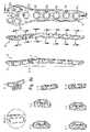
- FIG. 6different possibilities for the coupling of connection elements to a main plate of an implant in accordance with the invention
- FIGS. 7 a - 7 ffurther possibilities for the coupling of a connection element to a main plate of an implant in accordance with the invention or specific aspects of the main plate;
- FIGS. 8 a - 8 cdifferent views of a main plate in accordance with a further embodiment of the invention.
- FIG. 10different views of a connection element in accordance with a further embodiment of the invention.
- FIG. 1shows an implant in accordance with the invention consisting of a main plate 13 , of a plate-like outrigger 15 as well as of two connection elements 17 which is used here for the treatment of the humerus 11 , with the outrigger 15 serving for the fastening to bone fragments; with the humerus 11 , for example, to a tuberculum minus fracture.
- the outrigger plate 15does not extend in one plane, but is directly matched by bending to the anatomy of the bone 11 in the region destined for the use of the outrigger plate 15 .
- the outrigger plate 15made, for example, from titanium, is made in one piece with two elongate, wire-like connection elements 17 which are guided in each case through a passage 27 formed in the main plate 13 and extending approximately parallel to the main plate plane.
- the free ends of the connection elements 17are connected to one another by being twisted together, whereby an accidental pulling out of the connection elements 17 from the main plate 13 is avoided and a maximum spacing between the main plate 13 and the outrigger plate 15 is predetermined.
- connection elements 17can be brought into the respectively desired shape by bending, whereby the spatial structure of the implant required for the respective fracture can always be directly realised.
- FIG. 2shows an embodiment of an implant in accordance with the invention, in which the main plate 13 is provided with a hook-like continuation 29 with which the positioning of the main plate 13 at the bone is facilitated.
- the spatial offset or spacing between the main plate 13 and the outrigger 15can be changed prior to the final fixing of the connection elements 17 to the main plate 13 and the implant in accordance with the invention can be exactly matched in this manner to the respective bone fracture to be treated.
- the main plate 15is made in grid-shape and includes a plurality of ring sections 23 which are connected to one another by webs 21 whose length is smaller than the diameter of the ring sections 23 .
- Each ring section 23defines a passage through which a bone screw can be guided to fix the outrigger 15 to the bone to be treated.
- the main plate 13can be connected to a handle and/or to a targeting aid, such as was/were explained in the introductory part, via the two front bores 47 of the main plate 13 disposed closest to the hook 29 .
- a targeting aidsuch as was/were explained in the introductory part
- Such a handle or such a targeting aidis not a subject of the invention so that it is not considered in any more detail in the following.
- an outrigger plate 15 in accordance with the invention shown in FIGS. 3 and 4differ from one another, on the one hand, in that in the variant in accordance with FIG. 4 bores are formed in a central region in a full-area material, that is the outrigger 15 is provided in the form of a perforated plate, while in the variant in accordance with FIG. 3 individual ring sections 23 are connected to one another either directly or via webs 21 , whereby a continuous grid-like or mesh-like perforated structure is obtained.
- connection elements 17are each bent at their one free end to form eyelets 31 which are hooked into bores 25 of the outrigger plate 15 serving as fastening sections.
- connection elements 17are made in one piece with the outrigger plate 15 .
- Possible sectional lines 33are indicated by way of example by the broken lines in FIG. 3 along which the outrigger plate 15 can be cut to the respectively required shape by taking away one or more ring sections 23 .
- FIGS. 5 a - 5 cshow by way of example how different shapes and sizes of the outrigger plate 15 can be realized by a different number of ring elements 23 and a different manner of connection of the ring sections 23 to form a continuous am plate 15 .
- connection elements 17 in the examples of FIGS. 5 a - 5 care connected in one piece to the outrigger plate 15 , with either both connection elements 17 starting from the same ring section 23 (cf. FIG. 5 a ) or being able to be connected to different ring sections 23 (cf. FIGS. 5 b and 5 c ).
- connection elements 17formed here in each case as flexible wire
- the coupling of the connection elements 17can take place (from left to right) (i) by twisting together the free ends of two connection elements 17 pushed through the main plate 13 (cf. also FIG.
- connection elements 17projecting out of the main plate 13 in the plane of the main plate 13 ; (iii) by guiding only a single connection element 17 through a passage formed in the main plate 13 in the one direction and by guiding back this connection element 17 through a further passage formed in the main plate 13 in the other direction; or (iv) by bending over the free ends of the connection elements 17 projecting out of the main plate 13 perpendicular to the plane of the main plate 13 .
- connection of the main plate 13 to the outrigger plate 15 via the connection elements 17can take place prior to or during the operation.
- the spatial offset between the main plate 13 and the outrigger plate 15can be individually matched to the bone fracture to be treated in each case.
- FIGS. 7 a - 7 dshow further examples for the coupling of the connection elements 17 to the main plate 13 .
- the main plate 13can be provided with channels 35 which expand at the base side and thus form an under-cut into which correspondingly shaped, for example spherically expanded, free ends 37 of the connection elements 17 can be inserted in a manner secure against pulling out by pushing in from the side ( FIG. 7 a ) or by clipping in ( FIG. 7 b ).
- channels 35which expand at the base side and thus form an under-cut into which correspondingly shaped, for example spherically expanded, free ends 37 of the connection elements 17 can be inserted in a manner secure against pulling out by pushing in from the side ( FIG. 7 a ) or by clipping in ( FIG. 7 b ).
- connection elements 17are provided with fastening pins 39 which can be latched to the main plate 13 at correspondingly formed cut-outs thereof.
- connection elements 17are made in hook shape and are hooked into the main plate 13 at correspondingly formed cut-outs serving as a fastening section in each case.
- the main plate 13can additionally be provided with leadthroughs 43 through which the suturing needles or suturing material can be led. If such leadthroughs extend obliquely from the upper surface into a side surface of the main plate 13 , suture material can be pulled in, e.g. by means of a round needle, even with a main plate fixed to the bone.
- FIGS. 8 a , 8 b and 8 cshow different views of a preferred embodiment of a main plate 13 in accordance with the invention.
- the main plate 13can be used in conjunction with outrigger plates and connection elements which will be looked at in more detail in the following.
- the main plate 13can, however, also be used alone as a bone plate without an outrigger.
- the main plate 13has a relatively narrow section 115 which extends approximately over two thirds of its length and which is adjoined by a widened head section 117 which forms the further third of the plate length.
- a comparatively short end section 119adjoins the other end of the narrow section 115 and tapers constantly to approximately half the width of the narrow section 115 .
- the main plate 13is not planar, but is slightly curved in the direction of its longitudinal extent such that a gently swung wave-like extent is provided.
- the main plate 13extends rearwardly obliquely upwardly at a relatively low angle of inclination amounting to a few degrees, with the plate thickness being approximately constant up to a rear chamfer 121 at the short end section 119 and in particular lying in the range from approximately 4 to 6 mm.
- the plate thickness right at the end of the chamfered end section 119amounts to less than half the thickness in the narrow section 115 .
- the main plate 13likewise extends forwardly obliquely upwardly at a relatively low angle such that the head section 117 is raised with respect to the plate centre still belonging to the narrow section 115 , with, however—unlike in the rear region—the head section 117 running out approximately parallel to the centre part of the main plate 13 .
- the head section 117is provided with a chamfer 123 at the front end such that the head section 117 runs out in wedge shape precisely like the plate end.
- the plate 13has a relatively gently curved outer contour without edges with respect to its longitudinal extent.
- the plate 13is provided with a plurality of passages in the form of bores.
- a total of eight bores 125 with relatively large diametersserve to receive fastening elements in the form of bone screws.
- the large bores 125are each provided with an internal thread.
- Six large bores 125are arranged distributed in a sequential row, spaced apart substantially the same, along the central plane 127 of the plate 13 over the narrow section 115 up to and into the transition region to the head section 117 .
- the axes of these large bores 125extend at an inclination with respect to the centre plane 127 and/or with respect to a normal on a reference surface F of the plate 13 . This also applies to the two large bores 125 in the head section 117 which are arranged lying diametrically opposite one another symmetrically on both sides of the central plane 127 .
- the main plate 13is furthermore provided with three further bores 129 , 131 of—seen relatively—medium diameter size.
- the two bores 129 disposed symmetrically to the centre plane 127 at the front end of the head section 117 in the region of the chamfer 123serve to couple the plate 13 to a handle and/or to a targeting aid such as has already been described in the introductory part. This is not looked at in any detail at this point.
- the plate 13is provided with three small bores 133 which lie on the centre plane 127 and of which one is disposed on the rear chamfer 121 , one on the front chamfer 123 and one approximately between the large bores 125 formed in the head section 117 on the other side of the medium sized bore 131 .
- Marginal bores 135 , 137 formed in the marginal region on the head section 117 and transverse bores 139 extending perpendicular to the centre plane 127will be considered in more detail at another point.
- the bore 125 made as a threaded borecan be used in interaction with an adjacent bore 133 for the intermittent fastening of a handle (not shown).
- the bores 133 , 135 , 137can be used as fastening aids for pins or for threads which support soft tissues such as muscle ends or tendons. Such threads of bioabsorbable material are used when the soft tissues can anchor themselves sufficiently at a later time.
- the large bores 125are made in step shape.
- a large part region of the bores 125 starting from the upper plate siderespectively has a larger diameter and extends over a larger axial length than a small part region of the bores 125 opening at the lower plate side.
- the internal threadis respectively formed at the larger upper part region of the bores 125 .
- the sections B-B to H-H of the individual large bores 125(Nos. 1 to 8) and the section A-A in FIG. 8 b show that, with the exception of bores No. 3 (section C-C) and No. 4 (section D-D), the centre axes of the bores 125 extend in inclined form both with respect to a normal on the reference surface F (cf. section A-A in FIG. 8 b ) and with respect to the centre plane 127 of the plate 13 .
- the centre axes of the bores 125 with the Nos. 5 to 8are inclined by approximately 4° with respect to the centre plane 127 , while this angle of inclination is somewhat lower in the bores 125 with the Nos. 1 and 2 formed in the head section 117 and preferably amounts to approximately 3.5°.
- the centre axes of the bores 125 with the No. 3 (section C-C) and No. 4 (section D-D)lie in the centre plane 127 , but are inclined with respect to the mentioned normal on the reference surface F.
- FIG. 8 cin particular shows the design of the marginal bores 135 , 137 and of the transverse bores 139 .
- the marginal bores 135 formed in the rear region of the head section 117have a greater inclination with respect to the normal on the reference surface F than the marginal bores 137 formed in the front region of the head section 117 (section A-A).
- the transverse bores 139each extend perpendicular to the centre plane 127 of the plate 13 and have a comparatively small inner diameter which expands in each case towards the opening at the narrow sides of the plate 13 , as is shown in particular by the details E and F in FIG. 8 c .
- the narrow sides of the plate 113extend obliquely to the longitudinal axis of the transverse bores 139 in the region of the openings.
- transverse bores 139serve to link one or more outriggers by means of connection elements, provided in particular in the form of wires
- the marginal bores 135 , 137 and the bore 133 formed in the region of the front chamber 123 for the pulling through of suture materialare in particular provided using curved needles.
- FIG. 9shows a preferred embodiment of an outrigger 15 also termed an outrigger plate in the following.
- the outrigger 15comprises a coherent perforated plate section 153 in which differently sized bores are formed seemingly unordered, as well as a ring row section 155 of three rings sections which are arranged sequentially in a straight line, are connected to one another by webs 157 and each bound a bore.
- the outrigger 15includes three types of bores: large bores with which the ring row section 155 is exclusively provide have a diameter of approximately 5 mm, whereas the medium sized bores have a diameter of approximately 4 mm and the small bores 159 have a diameter of approximately 2.5 mm.
- the base area of the outrigger plate 15is smaller than that of the main plate 13 .
- the outrigger plate 15preferably has a maximum width in the range from 15 to 20 mm, preferably approximately 17.2 mm, and a maximum length in the range from 50 to 55 mm, preferably approximately 52.1 mm
- the maximum width in the main plate 13preferably amounts to 22 to 27 mm, preferably approximately 24.4 mm, and the maximum length to 90 to 95 mm, preferably approximately 93 mm.
- FIG. 10shows different views of a cerclage wire serving as a connection element 17 .
- the spacing between the two U limbs 163 of the wire 17corresponds to the spacing of the two small bores 159 in the outrigger plate 15 (cf. FIG. 9 ).
- the prefabricated wire 17can hereby be pushed through the two bores 159 without problem and be aligned relative to the outrigger plate 15 such that the two U limbs 163 extend parallel to the plane of the outrigger plate 15 , without the U base 161 extending beyond the large bore of the outrigger plate 15 located between the two small bores 159 .
- the U limbs 163 of the wire 17 projecting in this manner from the outrigger plate 15 coupled to the wire 17can subsequently be deformed in the respectively required manner and be connected to the main plate 13 in that its free ends are pushed through the transverse bores 139 likewise having the corresponding spacing and are latched to the opposite side of the main plate 13 , for example by bending over or twisting together, such that the wire 17 , and thus the outrigger 15 , is connected to the main plate 13 secure against being pulled out.
- the outrigger 15 and the wire 17which are made as separate components, can be connected to one another so firmly, e.g. by welding, prior to the operation, and in particular as part of the manufacture, that they can be handled as one unit during the operation.
- only one single outrigger 15is preferably connected to the main plate 13 via a prefabricated U-shaped wire 17 , e.g. in accordance with FIG. 10 .
- the main plate 13 and the outrigger 15are therefore only connected to one another at one side by means of the wire 17 , i.e. the wire 17 only extends—starting from one side of the main plate 13 —to the outrigger plate 15 .
- the outrigger plate 15which in the embodiment of FIG. 9 comprises the perforated plate section 153 comprising so-to-say a “heap” of bores and the ring row section 155 , which is in contrast small and elongate, has been selected with respect to its basic shape such that it is sufficiently large for all common fractures of the tuberculum minus and can be matched to the respective bone fracture to be treated by cutting to shape with an appropriate tool.
Landscapes
- Health & Medical Sciences (AREA)
- Orthopedic Medicine & Surgery (AREA)
- Surgery (AREA)
- Life Sciences & Earth Sciences (AREA)
- Heart & Thoracic Surgery (AREA)
- Nuclear Medicine, Radiotherapy & Molecular Imaging (AREA)
- Engineering & Computer Science (AREA)
- Biomedical Technology (AREA)
- Neurology (AREA)
- Medical Informatics (AREA)
- Molecular Biology (AREA)
- Animal Behavior & Ethology (AREA)
- General Health & Medical Sciences (AREA)
- Public Health (AREA)
- Veterinary Medicine (AREA)
- Surgical Instruments (AREA)
- Prostheses (AREA)
Abstract
Description
- 11 bone
- 13 main plate
- 15 outrigger
- 17 connection element
- 19 fastening element, bone screw
- 21 web
- 23 ring section
- 25 fastening section, bore
- 27 passage
- 29 continuation
- 31 eyelet
- 33 sectional line
- 35 channel
- 37 extension
- 39 fastening pin
- 41 hook-shaped end
- 43 leadthrough
- 45 fastening section, cut-out
- 47 bore for handle or targeting aid
- 115 narrow section
- 117 head section
- 119 end section
- 121 rear chamfer
- 123 front chamfer
- 125 large bore
- 127 centre plane
- 129 bore
- 131 bore
- 133 bore
- 135 marginal bore
- 137 marginal bore
- 139 transverse bore
- 141 recess
- 153 perforated plate section
- 155 ring row section
- 157 web
- 159 small bore of the outrigger
- 161 U base
- 163 U limb
- F reference surface of the main plate
Claims (26)
Applications Claiming Priority (4)
| Application Number | Priority Date | Filing Date | Title |
|---|---|---|---|
| EP03007543 | 2003-04-01 | ||
| EP03007543.6 | 2003-04-01 | ||
| EP04002710.4 | 2004-02-06 | ||
| EP04002710AEP1464295A3 (en) | 2003-04-01 | 2004-02-06 | Implant |
Publications (2)
| Publication Number | Publication Date |
|---|---|
| US20040225291A1 US20040225291A1 (en) | 2004-11-11 |
| US7731718B2true US7731718B2 (en) | 2010-06-08 |
Family
ID=32852235
Family Applications (1)
| Application Number | Title | Priority Date | Filing Date |
|---|---|---|---|
| US10/814,926Expired - Fee RelatedUS7731718B2 (en) | 2003-04-01 | 2004-03-31 | Implant for the treatment of bone fractures |
Country Status (3)
| Country | Link |
|---|---|
| US (1) | US7731718B2 (en) |
| EP (1) | EP1464295A3 (en) |
| JP (1) | JP4526291B2 (en) |
Cited By (43)
| Publication number | Priority date | Publication date | Assignee | Title |
|---|---|---|---|---|
| US20080021452A1 (en)* | 2006-07-18 | 2008-01-24 | Dustin Ducharme | Calcaneal plate |
| US20100191285A1 (en)* | 2003-06-11 | 2010-07-29 | Medicinelodge, Inc. Dba Imds Co-Innovation | Compact Line Locks and Methods |
| US20100331844A1 (en)* | 2003-08-28 | 2010-12-30 | Ellis Thomas J | Bone fixation system |
| US20110160856A1 (en)* | 2009-07-02 | 2011-06-30 | Medicinelodge, Inc. Dba Imds Co-Innovation | Systems and Methods for Zipknot ACL Fixation |
| US20110184413A1 (en)* | 2006-05-17 | 2011-07-28 | Gordon Slater | Ankle Fusion Plate |
| US20120046747A1 (en)* | 2004-09-07 | 2012-02-23 | Medicinelodge, Inc. Dba Imds Co-Innovation | Systems and methods for zipknot acl fixation |
| US20120095466A1 (en)* | 2010-10-19 | 2012-04-19 | Biomet Manufacturing Corp. | Orthopedic Plate Assembly for a Distal Radius Having Re-Contouring Features and Method for Using Same |
| US20130079828A1 (en)* | 2011-09-27 | 2013-03-28 | Steven Glickel | Distal Radius Volar Locking Plate With Extension for Ulnar Volar Fragment |
| US20130197518A1 (en)* | 2011-06-14 | 2013-08-01 | Amit Gupta | Intramedullary system for managing a bone fracture |
| WO2013113015A1 (en)* | 2012-01-26 | 2013-08-01 | Acute Innovations Llc | Clip for rib stabilization |
| US8535313B1 (en)* | 2011-03-14 | 2013-09-17 | Marcos V. Masson | Bone plate with suture retaining elements |
| US8546456B2 (en) | 2008-07-25 | 2013-10-01 | Smith & Nephew, Inc. | Fracture fixation systems |
| US8568417B2 (en) | 2009-12-18 | 2013-10-29 | Charles River Engineering Solutions And Technologies, Llc | Articulating tool and methods of using |
| US20160100933A1 (en)* | 2012-07-30 | 2016-04-14 | Conextions, Inc. | Soft tissue to bone repair devices, systems, and methods |
| US20160143663A1 (en)* | 2014-11-24 | 2016-05-26 | Stryker European Holdings I, Llc | Strut plate and cabling system |
| US9387020B2 (en) | 2011-01-10 | 2016-07-12 | Ascension Orthopedics, Inc. | Bone plate system for repair of proximal humeral fracture |
| US20160270830A1 (en)* | 2015-03-22 | 2016-09-22 | Rahul Vaidya | Method and Apparatus for Minimally Invasive Subcutaneous Treatment of Humerus Fractures |
| US9549768B2 (en) | 2014-04-17 | 2017-01-24 | Biomet Manufacturing, Llc | Medical implant system for securing bone fragments |
| US9775657B2 (en) | 2011-09-30 | 2017-10-03 | Acute Innovations Llc | Bone fixation system with opposed mounting portions |
| US9801670B2 (en) | 2014-06-30 | 2017-10-31 | DePuy Synthes Products, Inc. | Locking first metacarpal plate |
| USD816840S1 (en) | 2015-04-22 | 2018-05-01 | Flower Orthopedics Corporation | Proximal humeral fracture plate |
| US20190046327A1 (en)* | 2017-08-10 | 2019-02-14 | Hayward Surgical, L.L.C. | Apparatuses for Distal Fibula Replacement, and Related Methods |
| US10219804B2 (en) | 2012-07-30 | 2019-03-05 | Conextions, Inc. | Devices, systems, and methods for repairing soft tissue and attaching soft tissue to bone |
| US10238438B2 (en) | 2015-04-22 | 2019-03-26 | Flower Orthopedics Corporation | Proximal humeral fracture plate |
| US10660642B2 (en) | 2012-07-30 | 2020-05-26 | Conextions, Inc. | Soft tissue repair devices, systems, and methods |
| US10660643B2 (en) | 2012-07-30 | 2020-05-26 | Conextions, Inc. | Soft tissue repair devices, systems, and methods |
| US10835241B2 (en) | 2012-07-30 | 2020-11-17 | Conextions, Inc. | Devices, systems, and methods for repairing soft tissue and attaching soft tissue to bone |
| US10973509B2 (en) | 2017-12-20 | 2021-04-13 | Conextions, Inc. | Devices, systems, and methods for repairing soft tissue and attaching soft tissue to bone |
| US11253252B2 (en) | 2012-07-30 | 2022-02-22 | Conextions, Inc. | Devices, systems, and methods for repairing soft tissue and attaching soft tissue to bone |
| US11376129B2 (en) | 2017-08-10 | 2022-07-05 | Hayward Surgical, L.L.C. | Apparatuses for distal fibula replacement and related methods |
| US11547397B2 (en) | 2017-12-20 | 2023-01-10 | Conextions, Inc. | Devices, systems, and methods for repairing soft tissue and attaching soft tissue to bone |
| US11553949B2 (en)* | 2017-07-21 | 2023-01-17 | Biomet Manufacturing, Llc | Femoral fracture fixation device with posterior support portion |
| US11583384B2 (en) | 2014-03-12 | 2023-02-21 | Conextions, Inc. | Devices, systems, and methods for repairing soft tissue and attaching soft tissue to bone |
| US11696822B2 (en) | 2016-09-28 | 2023-07-11 | Conextions, Inc. | Devices, systems, and methods for repairing soft tissue and attaching soft tissue to bone |
| US11771481B2 (en) | 2021-03-08 | 2023-10-03 | Zimmer Biomet CMF and Thoracic, LLC | Sternal plates and methods of use |
| US11857232B2 (en) | 2019-06-24 | 2024-01-02 | Medartis Ag | Fracture fixation system and method |
| US11925397B2 (en) | 2020-06-25 | 2024-03-12 | Medartis Ag | System and method for bone fixation |
| US11944531B2 (en) | 2012-07-30 | 2024-04-02 | Conextions, Inc. | Devices, systems, and methods for repairing soft tissue and attaching soft tissue to bone |
| US11957334B2 (en) | 2012-07-30 | 2024-04-16 | Conextions, Inc. | Devices, systems, and methods for repairing soft tissue and attaching soft tissue to bone |
| US11986227B2 (en) | 2020-01-20 | 2024-05-21 | Trimed Inc. | Method and apparatus for maintaining a position of a bone fragment in relationship to another bone part |
| US11998252B2 (en) | 2020-11-18 | 2024-06-04 | Medartis Ag | System and method for bone fixation |
| US12102317B2 (en) | 2017-12-20 | 2024-10-01 | Conextions, Inc. | Devices, systems, and methods for repairing soft tissue and attaching soft tissue to bone |
| US12285197B2 (en) | 2008-10-10 | 2025-04-29 | Acumed Llc | Bone fixation system with opposed mounting portions |
Families Citing this family (73)
| Publication number | Priority date | Publication date | Assignee | Title |
|---|---|---|---|---|
| US5938664A (en)* | 1998-03-31 | 1999-08-17 | Zimmer, Inc. | Orthopaedic bone plate |
| US8475504B2 (en)* | 2007-07-19 | 2013-07-02 | Acumed Llc | Method of bone fixation with slender spanning members disposed outside bone |
| US20050240187A1 (en) | 2004-04-22 | 2005-10-27 | Huebner Randall J | Expanded fixation of bones |
| USD536453S1 (en)* | 2004-03-25 | 2007-02-06 | Precimed S.A. | Bone plate |
| US20060173458A1 (en)* | 2004-10-07 | 2006-08-03 | Micah Forstein | Bone fracture fixation system |
| US8394130B2 (en) | 2005-03-17 | 2013-03-12 | Biomet C.V. | Modular fracture fixation system |
| US7604657B2 (en) | 2005-09-19 | 2009-10-20 | Depuy Products, Inc. | Bone fixation plate with complex suture anchor locations |
| WO2006058221A2 (en) | 2004-11-24 | 2006-06-01 | Abdou Samy M | Devices and methods for inter-vertebral orthopedic device placement |
| ES2300967T3 (en)* | 2005-03-11 | 2008-06-16 | Orthofix S.R.L. | DEVICE FOR OSTEOSYNTHESIS OF PROXIMAL FRACTURES OF THE HUMER. |
| GB0505505D0 (en)* | 2005-03-17 | 2005-04-27 | Dall Desmond Meiring | Configurable bone fixation system |
| US20060276896A1 (en)* | 2005-06-02 | 2006-12-07 | Medicinelodge, Inc. | Bone implants with integrated line locks |
| WO2007056516A2 (en)* | 2005-11-09 | 2007-05-18 | Abdou M S | Bone fixation systems and methods of implantation |
| US8029551B2 (en)* | 2006-01-10 | 2011-10-04 | Running Donald E | Fracture fixation plate with cover sheath |
| US8523921B2 (en) | 2006-02-24 | 2013-09-03 | DePuy Synthes Products, LLC | Tibial plateau leveling osteotomy plate |
| US8226693B2 (en)* | 2006-06-16 | 2012-07-24 | Reimels William J | Bone bridge providing dynamic compression on bone fractures |
| JP4950579B2 (en)* | 2006-07-06 | 2012-06-13 | 株式会社ホムズ技研 | Intramedullary nail and orthopedic surgical instrument set |
| CA2661444C (en)* | 2006-08-15 | 2015-12-29 | Swissmedtechsolutions Ag | Trochanter retention plate |
| US20080077132A1 (en)* | 2006-09-25 | 2008-03-27 | Medoff Robert J | Bone fixation device having integral fixation member |
| US8398687B2 (en)* | 2006-12-06 | 2013-03-19 | Amei Technologies, Inc. | Volar plate fixation device |
| US8968318B2 (en) | 2007-02-28 | 2015-03-03 | DePuy Synthes Products, LLC | Grooved crimp with a set screw |
| US8628560B2 (en)* | 2007-03-08 | 2014-01-14 | DePuy Synthes Products, LLC | Orthopaedic instrumentation with integral load-bearing members |
| EP2397094B1 (en) | 2007-11-02 | 2013-06-26 | Biomet C.V. | Elbow fracture fixation system |
| CN101854873B (en)* | 2007-11-13 | 2013-03-13 | 新特斯有限责任公司 | Periprosthetic fracture repair |
| US8317842B2 (en) | 2007-11-30 | 2012-11-27 | Biomet C.V. | Distal tibia plating system |
| AU2008354730A1 (en)* | 2008-04-17 | 2009-10-22 | Toby Orthopaedics, Inc. | Soft tissue attachment system and clip |
| DE102009018104A1 (en)* | 2008-11-10 | 2010-05-12 | Friedrich Boysen Gmbh & Co. Kg | exhaust manifold |
| US8834532B2 (en)* | 2009-07-07 | 2014-09-16 | Zimmer Gmbh | Plate for the treatment of bone fractures |
| US8444680B2 (en)* | 2009-11-09 | 2013-05-21 | Arthrex, Inc. | Polyaxial bushing for locking plate |
| US8764806B2 (en) | 2009-12-07 | 2014-07-01 | Samy Abdou | Devices and methods for minimally invasive spinal stabilization and instrumentation |
| ES2525129T3 (en) | 2009-12-30 | 2014-12-17 | Medartis Ag | Osteosynthesis plate for the treatment of fractures near a joint or osteotomies |
| US8579945B2 (en) | 2010-08-13 | 2013-11-12 | DePuy Synthes Products, LLC | Bone stabilization device |
| EP2564797B1 (en) | 2011-08-31 | 2020-10-14 | Stryker European Holdings I, LLC | Bone place with hook portion |
| US8845728B1 (en) | 2011-09-23 | 2014-09-30 | Samy Abdou | Spinal fixation devices and methods of use |
| US9681902B2 (en) | 2012-02-13 | 2017-06-20 | Stryker European Holdings I, Llc | Attachment device for a bone plate |
| US20130226240A1 (en) | 2012-02-22 | 2013-08-29 | Samy Abdou | Spinous process fixation devices and methods of use |
| US9198767B2 (en) | 2012-08-28 | 2015-12-01 | Samy Abdou | Devices and methods for spinal stabilization and instrumentation |
| US9320617B2 (en) | 2012-10-22 | 2016-04-26 | Cogent Spine, LLC | Devices and methods for spinal stabilization and instrumentation |
| WO2014110421A1 (en)* | 2013-01-11 | 2014-07-17 | The Uab Research Foundation | Apparatus for the fixation of proximal humerus fractures |
| US9545276B2 (en)* | 2013-03-15 | 2017-01-17 | Aristotech Industries Gmbh | Fixation device and method of use for a lapidus-type plantar hallux valgus procedure |
| CN103445847A (en)* | 2013-07-03 | 2013-12-18 | 厦门大博颖精医疗器械有限公司 | Cable locking plate |
| EP3065656B1 (en) | 2013-11-05 | 2020-12-23 | Arthrex, Inc. | Tplo plate with suture holes for rotational stability |
| TWM483059U (en)* | 2014-03-25 | 2014-08-01 | Plus Biotechnology Co Ltd A | Femur fixing device |
| USD766434S1 (en)* | 2014-10-23 | 2016-09-13 | Paragon 28, Inc. | Bone plate |
| USD765844S1 (en)* | 2014-10-23 | 2016-09-06 | Paragon 28, Inc. | Bone plate |
| USD766439S1 (en)* | 2015-03-13 | 2016-09-13 | Paragon 28, Inc. | Bone plate |
| USD766437S1 (en)* | 2015-03-13 | 2016-09-13 | Paragon 28, Inc. | Bone plate |
| USD766438S1 (en)* | 2015-03-13 | 2016-09-13 | Paragon 28, Inc. | Single ray bone plate |
| US10857003B1 (en) | 2015-10-14 | 2020-12-08 | Samy Abdou | Devices and methods for vertebral stabilization |
| EP3184064B1 (en)* | 2015-12-23 | 2019-05-01 | Stryker European Holdings I, LLC | Bone plate with guiding channels |
| USD787059S1 (en)* | 2016-02-17 | 2017-05-16 | Karl Leibinger Medzintechnik GmbH & Co. KG | Jawbone implant |
| USD785178S1 (en)* | 2016-02-17 | 2017-04-25 | Karl Leibinger Medizintechnik Gmbh & Co. Kg | Zygomatic bone implant |
| USD785798S1 (en)* | 2016-02-17 | 2017-05-02 | Karl Leibinger Medizintechnik Gmbh & Co. Kg | Jawbone implant |
| USD786435S1 (en)* | 2016-02-17 | 2017-05-09 | Karl Leibinger Medizintechnik Gmbh & Co. Kg | Jawbone implant |
| USD787060S1 (en)* | 2016-02-17 | 2017-05-16 | Karl Leibinger Medizintechnik Gmbh & Co. Kg | Jawbone implant |
| USD787058S1 (en)* | 2016-02-17 | 2017-05-16 | Karl Leibinger Medizintechnik Gmbh & Co. Kg | Eye-socket implant |
| USD786436S1 (en)* | 2016-02-17 | 2017-05-09 | Karl Leibinger Medizintechnik Gmbh & Co. Kg | Cheekbone implant |
| CN105662567A (en)* | 2016-03-16 | 2016-06-15 | 苏州瑞华医院有限公司 | Bone plate provided with grooves |
| CN106264697A (en)* | 2016-08-31 | 2017-01-04 | 常州华森医疗器械有限公司 | Greater tuberosity anatomical form steel plate |
| WO2018067538A1 (en)* | 2016-10-04 | 2018-04-12 | Acumed Llc | Fixation system and method for hoffa fractures |
| EP3522802B1 (en)* | 2016-10-07 | 2024-10-23 | Acumed LLC | System for bone fixation using a plate straddled by a retainer |
| US10973648B1 (en) | 2016-10-25 | 2021-04-13 | Samy Abdou | Devices and methods for vertebral bone realignment |
| US10744000B1 (en) | 2016-10-25 | 2020-08-18 | Samy Abdou | Devices and methods for vertebral bone realignment |
| CN106667569A (en)* | 2017-03-24 | 2017-05-17 | 上海市第五人民医院 | Acromioclavicular hook plate capable of repairing coracoclavicular ligament |
| USD869657S1 (en)* | 2017-07-31 | 2019-12-10 | Crossroads Extremity Systems, Llc | Bone plate |
| EP3784176B1 (en)* | 2018-04-23 | 2025-08-27 | ECA Medical Instruments | Flexible adjustable radiopaque trial plate |
| USD874004S1 (en)* | 2018-09-26 | 2020-01-28 | Paragon 28, Inc. | Bone plate |
| US11179248B2 (en) | 2018-10-02 | 2021-11-23 | Samy Abdou | Devices and methods for spinal implantation |
| USD874650S1 (en)* | 2018-10-23 | 2020-02-04 | DePuy Synthes Products, Inc. | Distal femur plate |
| EP4342398A3 (en)* | 2020-05-19 | 2024-05-29 | Smith & Nephew, Inc. | Periprosthetic bone plate |
| DE102020209981A1 (en)* | 2020-08-06 | 2022-02-10 | Karl Leibinger Medizintechnik Gmbh & Co. Kg | implant system |
| US12343050B2 (en)* | 2021-08-17 | 2025-07-01 | Ps Ortho Llc | Bone fixation devices, systems, and methods |
| US11963847B2 (en) | 2021-11-03 | 2024-04-23 | DePuy Synthes Products, Inc. | TPLO plate compression system and method |
| US12402923B2 (en) | 2022-10-04 | 2025-09-02 | DePuy Synthes Products, Inc. | Offset hole for TPLO compression |
Citations (43)
| Publication number | Priority date | Publication date | Assignee | Title |
|---|---|---|---|---|
| US1118773A (en) | 1913-10-31 | 1914-11-24 | Walter H Hout | Liquid-gage. |
| US3386799A (en) | 1965-11-16 | 1968-06-04 | Bell Telephone Labor Inc | Growth of yttrium iron garnet |
| US3561437A (en) | 1967-11-08 | 1971-02-09 | Jose Luis Orlich | Apparatus for fixing fractures of the femur |
| US3604414A (en) | 1968-08-29 | 1971-09-14 | Nicomedes Borges | Bone setting device |
| US3741205A (en) | 1971-06-14 | 1973-06-26 | K Markolf | Bone fixation plate |
| US3807394A (en) | 1971-08-19 | 1974-04-30 | Nat Res Dev | Fracture fixing device |
| US3814089A (en) | 1971-09-24 | 1974-06-04 | W Deyerle | Drill jig for total hip prosthesis |
| FR2291734A1 (en) | 1974-11-25 | 1976-06-18 | Tornier Rene | Metal screw and spar for humeral support - has transverse rod engaging in humerus condyles and splint distorted to fit against humerus |
| US4096857A (en) | 1976-01-20 | 1978-06-27 | Messerschmitt-Boelkow-Blohm Gmbh | Telescopically adjustable surgical instrument |
| DE2705154A1 (en) | 1977-02-08 | 1978-08-10 | Baumann Friedrich | BONE MARROW NAIL AND TARGET DEVICE FOR ITS ANCHORING IN THE MARULAR CANAL |
| US4465065A (en) | 1983-01-07 | 1984-08-14 | Yechiel Gotfried | Surgical device for connection of fractured bones |
| WO1989009037A1 (en) | 1988-04-01 | 1989-10-05 | The Trustees Of Columbia University In The City Of | Dual-taper, asymmetric hole placement in reconstruction and fracture plates |
| US4957496A (en) | 1988-11-11 | 1990-09-18 | Mecron Medizinische Produkte Gmbh | Slotted slide plate assembly for osteosynthesis |
| US5006120A (en) | 1989-10-10 | 1991-04-09 | Carter Peter R | Distal radial fracture set and method for repairing distal radial fractures |
| US5066296A (en) | 1989-02-02 | 1991-11-19 | Pfizer Hopsital Products Group, Inc. | Apparatus for treating a fracture |
| CA2047521A1 (en) | 1990-07-23 | 1992-01-24 | Robert Frigg | Osteosynthetic plate |
| US5376126A (en)* | 1993-11-12 | 1994-12-27 | Lin; Chih-I | Artificial acetabular joint replacing device |
| EP0491382B1 (en) | 1990-12-19 | 1996-08-21 | Kabushiki Kaisha Toshiba | Magnetic head base |
| EP0791338A2 (en) | 1996-02-22 | 1997-08-27 | Kwan-Ho Chan | A surgical fastener device for use in bone fracture fixation |
| US5665089A (en) | 1992-03-19 | 1997-09-09 | Dall; Desmond Meiring | Bone fixation system |
| JPH10179605A (en) | 1996-12-10 | 1998-07-07 | Johnson & Johnson Professional Inc | Bone fixing instrument |
| EP0897233A2 (en) | 1997-08-12 | 1999-02-17 | ProNet Tracking Systems, Inc. | A method and system for radio-location determination |
| US5993452A (en)* | 1998-08-24 | 1999-11-30 | Biomet Inc. | Cerclage system |
| US6066141A (en)* | 1997-07-22 | 2000-05-23 | Dall; Desmond Meiring | Bone grip |
| US6123709A (en)* | 1997-07-25 | 2000-09-26 | Jones; Andrew R. | Bone buttress plate and method of using same |
| US20010051815A1 (en)* | 2000-03-15 | 2001-12-13 | Esplin Vermon S. | Soft tissue anchor |
| US6348052B1 (en) | 1996-07-16 | 2002-02-19 | Giacomo J. Sammarco | Internal fixation plate |
| US20020062127A1 (en) | 1998-02-18 | 2002-05-23 | W.L. Lorenz | Method and apparatus for mandibular osteosynthesis |
| US20020128654A1 (en)* | 1998-02-18 | 2002-09-12 | Steger Shon D. | Method and apparatus for bone fracture fixation |
| US20020143336A1 (en)* | 2001-02-23 | 2002-10-03 | Hearn James P. | Sternum fixation device |
| US20020183753A1 (en) | 1995-06-26 | 2002-12-05 | Manderson Easton L. | Rod implant for osteosynthesis of long bones |
| DE10226074A1 (en) | 2001-06-13 | 2003-01-16 | Willmen Hans Rainer | Bone fracture osteosynthesis appliance consists of binders with web of material in which are holes for fastening pins |
| FR2827500A1 (en) | 2001-07-17 | 2003-01-24 | Tornier Sa | Long bone osteosynthesis plate has fastening tongues with holes for anchoring screws extending beyond main body of plate |
| US6514274B1 (en)* | 2000-02-25 | 2003-02-04 | Arthrotek, Inc. | Method and apparatus for rotator cuff repair |
| US6520965B2 (en)* | 2001-05-23 | 2003-02-18 | Alan Chervitz | Apparatus and method for orthopedic fixation |
| WO2003032849A1 (en)* | 2001-10-17 | 2003-04-24 | Spinevision | System of holding at least two vertebrae together for the purpose of spinal osteosynthesis |
| US6576018B1 (en)* | 2000-06-23 | 2003-06-10 | Edward S. Holt | Apparatus configuration and method for treating flatfoot |
| US20030130661A1 (en)* | 2002-01-08 | 2003-07-10 | Osman Said G. | Uni-directional dynamic spinal fixation device |
| US20040087954A1 (en)* | 2002-08-28 | 2004-05-06 | Allen C . Wayne | Systems, methods, and apparatuses for clamping and reclamping an orthopedic surgical cable |
| US20040097937A1 (en) | 2002-11-19 | 2004-05-20 | Sandi Pike | Orthopedic bone plate |
| US20040116931A1 (en)* | 2002-12-17 | 2004-06-17 | Carlson Gregory D. | Vertebrae fixation device and method of use |
| US20040116930A1 (en) | 2002-06-10 | 2004-06-17 | O'driscoll Shawn W. | Bone plates |
| US7207993B1 (en)* | 2000-02-03 | 2007-04-24 | Pioneer Laboratories, Inc. | Apparatus and method for repairing the femur |
Family Cites Families (3)
| Publication number | Priority date | Publication date | Assignee | Title |
|---|---|---|---|---|
| US5006210A (en)* | 1989-02-06 | 1991-04-09 | Iowa State University Research Foundation, Inc. | Means and method for capillary zone electrophoresis with laser-induced indirect fluorescence detection |
| DE19952359C1 (en)* | 1999-10-30 | 2001-03-22 | Aesculap Ag & Co Kg | Surgical connection has coupling element, two placement elements, bone plates, and holders |
| US6338734B1 (en)* | 2000-03-14 | 2002-01-15 | Biomet, Inc. | Method and apparatus for trochanter fixation |
- 2004
- 2004-02-06EPEP04002710Apatent/EP1464295A3/ennot_activeCeased
- 2004-03-30JPJP2004099084Apatent/JP4526291B2/ennot_activeExpired - Fee Related
- 2004-03-31USUS10/814,926patent/US7731718B2/ennot_activeExpired - Fee Related
Patent Citations (48)
| Publication number | Priority date | Publication date | Assignee | Title |
|---|---|---|---|---|
| US1118773A (en) | 1913-10-31 | 1914-11-24 | Walter H Hout | Liquid-gage. |
| US3386799A (en) | 1965-11-16 | 1968-06-04 | Bell Telephone Labor Inc | Growth of yttrium iron garnet |
| US3561437A (en) | 1967-11-08 | 1971-02-09 | Jose Luis Orlich | Apparatus for fixing fractures of the femur |
| US3604414A (en) | 1968-08-29 | 1971-09-14 | Nicomedes Borges | Bone setting device |
| US3741205A (en) | 1971-06-14 | 1973-06-26 | K Markolf | Bone fixation plate |
| US3807394A (en) | 1971-08-19 | 1974-04-30 | Nat Res Dev | Fracture fixing device |
| US3814089A (en) | 1971-09-24 | 1974-06-04 | W Deyerle | Drill jig for total hip prosthesis |
| FR2291734A1 (en) | 1974-11-25 | 1976-06-18 | Tornier Rene | Metal screw and spar for humeral support - has transverse rod engaging in humerus condyles and splint distorted to fit against humerus |
| US4096857A (en) | 1976-01-20 | 1978-06-27 | Messerschmitt-Boelkow-Blohm Gmbh | Telescopically adjustable surgical instrument |
| DE2705154A1 (en) | 1977-02-08 | 1978-08-10 | Baumann Friedrich | BONE MARROW NAIL AND TARGET DEVICE FOR ITS ANCHORING IN THE MARULAR CANAL |
| US4465065A (en) | 1983-01-07 | 1984-08-14 | Yechiel Gotfried | Surgical device for connection of fractured bones |
| WO1989009037A1 (en) | 1988-04-01 | 1989-10-05 | The Trustees Of Columbia University In The City Of | Dual-taper, asymmetric hole placement in reconstruction and fracture plates |
| US4957496A (en) | 1988-11-11 | 1990-09-18 | Mecron Medizinische Produkte Gmbh | Slotted slide plate assembly for osteosynthesis |
| US5066296A (en) | 1989-02-02 | 1991-11-19 | Pfizer Hopsital Products Group, Inc. | Apparatus for treating a fracture |
| US5006120A (en) | 1989-10-10 | 1991-04-09 | Carter Peter R | Distal radial fracture set and method for repairing distal radial fractures |
| CA2047521A1 (en) | 1990-07-23 | 1992-01-24 | Robert Frigg | Osteosynthetic plate |
| EP0468192B1 (en) | 1990-07-23 | 1996-09-11 | Synthes AG, Chur | Osteosynthetic plate |
| EP0491382B1 (en) | 1990-12-19 | 1996-08-21 | Kabushiki Kaisha Toshiba | Magnetic head base |
| US5665089A (en) | 1992-03-19 | 1997-09-09 | Dall; Desmond Meiring | Bone fixation system |
| JP3388741B2 (en) | 1992-03-19 | 2003-03-24 | メイリング ドール,デスモンド | Bone fixation system |
| US5376126A (en)* | 1993-11-12 | 1994-12-27 | Lin; Chih-I | Artificial acetabular joint replacing device |
| US20020183753A1 (en) | 1995-06-26 | 2002-12-05 | Manderson Easton L. | Rod implant for osteosynthesis of long bones |
| EP0791338A2 (en) | 1996-02-22 | 1997-08-27 | Kwan-Ho Chan | A surgical fastener device for use in bone fracture fixation |
| US6348052B1 (en) | 1996-07-16 | 2002-02-19 | Giacomo J. Sammarco | Internal fixation plate |
| US5797916A (en) | 1996-12-10 | 1998-08-25 | Johnson & Johnson Professional, Inc. | Trochanteric reattachment cerclage device |
| JPH10179605A (en) | 1996-12-10 | 1998-07-07 | Johnson & Johnson Professional Inc | Bone fixing instrument |
| US6066141A (en)* | 1997-07-22 | 2000-05-23 | Dall; Desmond Meiring | Bone grip |
| US6123709A (en)* | 1997-07-25 | 2000-09-26 | Jones; Andrew R. | Bone buttress plate and method of using same |
| EP0897233A2 (en) | 1997-08-12 | 1999-02-17 | ProNet Tracking Systems, Inc. | A method and system for radio-location determination |
| US20020062127A1 (en) | 1998-02-18 | 2002-05-23 | W.L. Lorenz | Method and apparatus for mandibular osteosynthesis |
| US20020128654A1 (en)* | 1998-02-18 | 2002-09-12 | Steger Shon D. | Method and apparatus for bone fracture fixation |
| US5993452A (en)* | 1998-08-24 | 1999-11-30 | Biomet Inc. | Cerclage system |
| US7207993B1 (en)* | 2000-02-03 | 2007-04-24 | Pioneer Laboratories, Inc. | Apparatus and method for repairing the femur |
| US6514274B1 (en)* | 2000-02-25 | 2003-02-04 | Arthrotek, Inc. | Method and apparatus for rotator cuff repair |
| US20010051815A1 (en)* | 2000-03-15 | 2001-12-13 | Esplin Vermon S. | Soft tissue anchor |
| US6576018B1 (en)* | 2000-06-23 | 2003-06-10 | Edward S. Holt | Apparatus configuration and method for treating flatfoot |
| US20020143336A1 (en)* | 2001-02-23 | 2002-10-03 | Hearn James P. | Sternum fixation device |
| US6520965B2 (en)* | 2001-05-23 | 2003-02-18 | Alan Chervitz | Apparatus and method for orthopedic fixation |
| DE10226074A1 (en) | 2001-06-13 | 2003-01-16 | Willmen Hans Rainer | Bone fracture osteosynthesis appliance consists of binders with web of material in which are holes for fastening pins |
| FR2827500A1 (en) | 2001-07-17 | 2003-01-24 | Tornier Sa | Long bone osteosynthesis plate has fastening tongues with holes for anchoring screws extending beyond main body of plate |
| US7335204B2 (en) | 2001-07-17 | 2008-02-26 | Tornier Sa | Osteosynthesis plate for the upper end of the arm bone |
| WO2003032849A1 (en)* | 2001-10-17 | 2003-04-24 | Spinevision | System of holding at least two vertebrae together for the purpose of spinal osteosynthesis |
| US20030130661A1 (en)* | 2002-01-08 | 2003-07-10 | Osman Said G. | Uni-directional dynamic spinal fixation device |
| US6932820B2 (en)* | 2002-01-08 | 2005-08-23 | Said G. Osman | Uni-directional dynamic spinal fixation device |
| US20040116930A1 (en) | 2002-06-10 | 2004-06-17 | O'driscoll Shawn W. | Bone plates |
| US20040087954A1 (en)* | 2002-08-28 | 2004-05-06 | Allen C . Wayne | Systems, methods, and apparatuses for clamping and reclamping an orthopedic surgical cable |
| US20040097937A1 (en) | 2002-11-19 | 2004-05-20 | Sandi Pike | Orthopedic bone plate |
| US20040116931A1 (en)* | 2002-12-17 | 2004-06-17 | Carlson Gregory D. | Vertebrae fixation device and method of use |
Cited By (67)
| Publication number | Priority date | Publication date | Assignee | Title |
|---|---|---|---|---|
| US20100191285A1 (en)* | 2003-06-11 | 2010-07-29 | Medicinelodge, Inc. Dba Imds Co-Innovation | Compact Line Locks and Methods |
| US9265498B2 (en) | 2003-06-11 | 2016-02-23 | Imds Llc | Compact line locks and methods |
| US8388655B2 (en) | 2003-06-11 | 2013-03-05 | Imds Corporation | Compact line locks and methods |
| US8632573B2 (en) | 2003-08-28 | 2014-01-21 | Thomas J. Ellis | Bone fixation system |
| US20100331844A1 (en)* | 2003-08-28 | 2010-12-30 | Ellis Thomas J | Bone fixation system |
| US20120046747A1 (en)* | 2004-09-07 | 2012-02-23 | Medicinelodge, Inc. Dba Imds Co-Innovation | Systems and methods for zipknot acl fixation |
| US20110184413A1 (en)* | 2006-05-17 | 2011-07-28 | Gordon Slater | Ankle Fusion Plate |
| US20080021452A1 (en)* | 2006-07-18 | 2008-01-24 | Dustin Ducharme | Calcaneal plate |
| US8057520B2 (en)* | 2006-07-18 | 2011-11-15 | Orthohelix Surgical Designs, Inc. | Calcaneal plate |
| US8546456B2 (en) | 2008-07-25 | 2013-10-01 | Smith & Nephew, Inc. | Fracture fixation systems |
| US9730740B2 (en) | 2008-07-25 | 2017-08-15 | Smith & Nephew, Inc. | Fracture fixation systems |
| US12285197B2 (en) | 2008-10-10 | 2025-04-29 | Acumed Llc | Bone fixation system with opposed mounting portions |
| US9808297B2 (en) | 2008-10-10 | 2017-11-07 | Acute Innovations Llc | Bone fixation system with opposed mounting portions |
| US11083504B2 (en) | 2008-10-10 | 2021-08-10 | Acumed Llc | Bone fixation system with opposed mounting portions |
| US11911083B2 (en) | 2008-10-10 | 2024-02-27 | Acumed Llc | Bone fixation system with opposed mounting portions |
| US20110160856A1 (en)* | 2009-07-02 | 2011-06-30 | Medicinelodge, Inc. Dba Imds Co-Innovation | Systems and Methods for Zipknot ACL Fixation |
| US8568417B2 (en) | 2009-12-18 | 2013-10-29 | Charles River Engineering Solutions And Technologies, Llc | Articulating tool and methods of using |
| US11033306B2 (en) | 2009-12-18 | 2021-06-15 | Charles River Engineering Solutions And Technologies, Llc | Articulating tool and methods of using |
| US9924986B2 (en) | 2009-12-18 | 2018-03-27 | Charles River Engineering Solutions And Technologies, Llc | Articulating tool and methods of using |
| US9173690B2 (en) | 2010-10-19 | 2015-11-03 | Biomet Manufacturing, Llc | Orthopedic plate assembly for a distal radius having re-contouring features and method for using same |
| US8518042B2 (en)* | 2010-10-19 | 2013-08-27 | Biomet Manufacturing, Llc | Orthopedic plate assembly for a distal radius having re-contouring features and method for using same |
| US20120095466A1 (en)* | 2010-10-19 | 2012-04-19 | Biomet Manufacturing Corp. | Orthopedic Plate Assembly for a Distal Radius Having Re-Contouring Features and Method for Using Same |
| US9387020B2 (en) | 2011-01-10 | 2016-07-12 | Ascension Orthopedics, Inc. | Bone plate system for repair of proximal humeral fracture |
| US8535313B1 (en)* | 2011-03-14 | 2013-09-17 | Marcos V. Masson | Bone plate with suture retaining elements |
| US20130197518A1 (en)* | 2011-06-14 | 2013-08-01 | Amit Gupta | Intramedullary system for managing a bone fracture |
| US8992528B2 (en)* | 2011-06-14 | 2015-03-31 | Amit Gupta | Intramedullary system for managing a bone fracture |
| US20130079828A1 (en)* | 2011-09-27 | 2013-03-28 | Steven Glickel | Distal Radius Volar Locking Plate With Extension for Ulnar Volar Fragment |
| US9220549B2 (en)* | 2011-09-27 | 2015-12-29 | Steven Glickel | Distal radius volar locking plate with extension for ulnar volar fragment |
| US9775657B2 (en) | 2011-09-30 | 2017-10-03 | Acute Innovations Llc | Bone fixation system with opposed mounting portions |
| US9237910B2 (en) | 2012-01-26 | 2016-01-19 | Acute Innovations Llc | Clip for rib stabilization |
| WO2013113015A1 (en)* | 2012-01-26 | 2013-08-01 | Acute Innovations Llc | Clip for rib stabilization |
| US11446024B2 (en) | 2012-07-30 | 2022-09-20 | Conextions, Inc. | Devices, systems, and methods for repairing soft tissue and attaching soft tissue to bone |
| US11957334B2 (en) | 2012-07-30 | 2024-04-16 | Conextions, Inc. | Devices, systems, and methods for repairing soft tissue and attaching soft tissue to bone |
| US11701218B2 (en) | 2012-07-30 | 2023-07-18 | Conextions, Inc. | Soft tissue to bone repair devices, systems, and methods |
| US20160100933A1 (en)* | 2012-07-30 | 2016-04-14 | Conextions, Inc. | Soft tissue to bone repair devices, systems, and methods |
| US10219804B2 (en) | 2012-07-30 | 2019-03-05 | Conextions, Inc. | Devices, systems, and methods for repairing soft tissue and attaching soft tissue to bone |
| US11944531B2 (en) | 2012-07-30 | 2024-04-02 | Conextions, Inc. | Devices, systems, and methods for repairing soft tissue and attaching soft tissue to bone |
| US10390935B2 (en)* | 2012-07-30 | 2019-08-27 | Conextions, Inc. | Soft tissue to bone repair devices, systems, and methods |
| US11980360B2 (en) | 2012-07-30 | 2024-05-14 | Conextions, Inc. | Devices, systems, and methods for repairing soft tissue and attaching soft tissue to bone |
| US11253252B2 (en) | 2012-07-30 | 2022-02-22 | Conextions, Inc. | Devices, systems, and methods for repairing soft tissue and attaching soft tissue to bone |
| US10660642B2 (en) | 2012-07-30 | 2020-05-26 | Conextions, Inc. | Soft tissue repair devices, systems, and methods |
| US10660643B2 (en) | 2012-07-30 | 2020-05-26 | Conextions, Inc. | Soft tissue repair devices, systems, and methods |
| US10835241B2 (en) | 2012-07-30 | 2020-11-17 | Conextions, Inc. | Devices, systems, and methods for repairing soft tissue and attaching soft tissue to bone |
| US11583384B2 (en) | 2014-03-12 | 2023-02-21 | Conextions, Inc. | Devices, systems, and methods for repairing soft tissue and attaching soft tissue to bone |
| US9549768B2 (en) | 2014-04-17 | 2017-01-24 | Biomet Manufacturing, Llc | Medical implant system for securing bone fragments |
| US9801670B2 (en) | 2014-06-30 | 2017-10-31 | DePuy Synthes Products, Inc. | Locking first metacarpal plate |
| US10092338B2 (en) | 2014-06-30 | 2018-10-09 | DePuy Synthes Products, Inc. | Locking first metacarpal plate |
| US11457954B2 (en) | 2014-11-24 | 2022-10-04 | Stryker European Operations Holdings Llc | Strut plate and cabling system |
| US20160143663A1 (en)* | 2014-11-24 | 2016-05-26 | Stryker European Holdings I, Llc | Strut plate and cabling system |
| US20160270830A1 (en)* | 2015-03-22 | 2016-09-22 | Rahul Vaidya | Method and Apparatus for Minimally Invasive Subcutaneous Treatment of Humerus Fractures |
| US10966766B2 (en) | 2015-04-22 | 2021-04-06 | Anup A. Shah | Proximal humeral fracture plate |
| US10238438B2 (en) | 2015-04-22 | 2019-03-26 | Flower Orthopedics Corporation | Proximal humeral fracture plate |
| USD816840S1 (en) | 2015-04-22 | 2018-05-01 | Flower Orthopedics Corporation | Proximal humeral fracture plate |
| USD871578S1 (en) | 2015-04-22 | 2019-12-31 | Anup A. Shah | Proximal humeral fracture plate |
| US11696822B2 (en) | 2016-09-28 | 2023-07-11 | Conextions, Inc. | Devices, systems, and methods for repairing soft tissue and attaching soft tissue to bone |
| US11553949B2 (en)* | 2017-07-21 | 2023-01-17 | Biomet Manufacturing, Llc | Femoral fracture fixation device with posterior support portion |
| US11376129B2 (en) | 2017-08-10 | 2022-07-05 | Hayward Surgical, L.L.C. | Apparatuses for distal fibula replacement and related methods |
| US10456266B2 (en)* | 2017-08-10 | 2019-10-29 | Hayward Surgical, L.L.C. | Apparatuses for distal fibula replacement, and related methods |
| US20190046327A1 (en)* | 2017-08-10 | 2019-02-14 | Hayward Surgical, L.L.C. | Apparatuses for Distal Fibula Replacement, and Related Methods |
| US11547397B2 (en) | 2017-12-20 | 2023-01-10 | Conextions, Inc. | Devices, systems, and methods for repairing soft tissue and attaching soft tissue to bone |
| US10973509B2 (en) | 2017-12-20 | 2021-04-13 | Conextions, Inc. | Devices, systems, and methods for repairing soft tissue and attaching soft tissue to bone |
| US12102317B2 (en) | 2017-12-20 | 2024-10-01 | Conextions, Inc. | Devices, systems, and methods for repairing soft tissue and attaching soft tissue to bone |
| US11857232B2 (en) | 2019-06-24 | 2024-01-02 | Medartis Ag | Fracture fixation system and method |
| US11986227B2 (en) | 2020-01-20 | 2024-05-21 | Trimed Inc. | Method and apparatus for maintaining a position of a bone fragment in relationship to another bone part |
| US11925397B2 (en) | 2020-06-25 | 2024-03-12 | Medartis Ag | System and method for bone fixation |
| US11998252B2 (en) | 2020-11-18 | 2024-06-04 | Medartis Ag | System and method for bone fixation |
| US11771481B2 (en) | 2021-03-08 | 2023-10-03 | Zimmer Biomet CMF and Thoracic, LLC | Sternal plates and methods of use |
Also Published As
| Publication number | Publication date |
|---|---|
| EP1464295A2 (en) | 2004-10-06 |
| JP2004305734A (en) | 2004-11-04 |
| US20040225291A1 (en) | 2004-11-11 |
| EP1464295A3 (en) | 2006-04-26 |
| JP4526291B2 (en) | 2010-08-18 |
Similar Documents
| Publication | Publication Date | Title |
|---|---|---|
| US7731718B2 (en) | Implant for the treatment of bone fractures | |
| US7658750B2 (en) | Suture anchoring system and method | |
| US8062363B2 (en) | Tendon repair apparatus and method | |
| EP2140823B1 (en) | Pin assembly for operation | |
| EP3355813B1 (en) | Modular bone screw for surgical fixation to bone | |
| JP4748813B2 (en) | Absorbent fixture and application equipment | |
| US5814070A (en) | Suture anchor and driver | |
| JP4002302B2 (en) | Oral fixture | |
| US5997542A (en) | Surgical wire assembly and method of use | |
| EP2224858B1 (en) | Anchor assembly | |
| EP1933740B1 (en) | Cable and crimp for bone surgery | |
| EP0592960A2 (en) | Sternum closure buckle | |
| EP2869771B1 (en) | Device for tissue ligation | |
| EP0847730A1 (en) | Trochanteric reattachment cerclage device | |
| EP1712198A2 (en) | Bone fixation device for surgical operation, cutting device and band head for the same | |
| US8992582B1 (en) | Fixation devices and method | |
| US7799000B2 (en) | Fixation apparatus for a medical device | |
| JP2024038484A (en) | Devices, systems, and methods for repairing soft tissue and attaching soft tissue to bone | |
| US20170172625A1 (en) | Medical device | |
| EP0867149A1 (en) | Surgical bone fixation apparatus | |
| US20080200993A1 (en) | Temporal Brow Lifting and Fixation Device | |
| CN104114202A (en) | Drug eluting insert for implantable body | |
| TWI572317B (en) | In vivo fixation device | |
| CN116672056A (en) | Orthopedic belt wire screw assembly and guide | |
| US20200360065A1 (en) | Zip-fix: a circumferential rapid fixation devices/implant system for comminuted or simple fractures of tubular bone |
Legal Events
| Date | Code | Title | Description |
|---|---|---|---|
| AS | Assignment | Owner name:CENTERPULSE ORTHOPEDICS LTD., SWITZERLAND Free format text:ASSIGNMENT OF ASSIGNORS INTEREST;ASSIGNORS:SCHWAMMBERGER, ANDY;VELIKOV, JORDAN;REEL/FRAME:015557/0374 Effective date:20040609 Owner name:CENTERPULSE ORTHOPEDICS LTD.,SWITZERLAND Free format text:ASSIGNMENT OF ASSIGNORS INTEREST;ASSIGNORS:SCHWAMMBERGER, ANDY;VELIKOV, JORDAN;REEL/FRAME:015557/0374 Effective date:20040609 | |
| AS | Assignment | Owner name:ZIMMER GMBH,SWITZERLAND Free format text:TRANSFORMATION WITHOUT LIQUIDATION;ASSIGNOR:CENTERPULSE ORTHOPEDICS LTD;REEL/FRAME:017897/0708 Effective date:20040630 Owner name:ZIMMER GMBH, SWITZERLAND Free format text:TRANSFORMATION WITHOUT LIQUIDATION;ASSIGNOR:CENTERPULSE ORTHOPEDICS LTD;REEL/FRAME:017897/0708 Effective date:20040630 | |
| FEPP | Fee payment procedure | Free format text:PAYER NUMBER DE-ASSIGNED (ORIGINAL EVENT CODE: RMPN); ENTITY STATUS OF PATENT OWNER: LARGE ENTITY Free format text:PAYOR NUMBER ASSIGNED (ORIGINAL EVENT CODE: ASPN); ENTITY STATUS OF PATENT OWNER: LARGE ENTITY | |
| FEPP | Fee payment procedure | Free format text:PAYER NUMBER DE-ASSIGNED (ORIGINAL EVENT CODE: RMPN); ENTITY STATUS OF PATENT OWNER: LARGE ENTITY Free format text:PAYOR NUMBER ASSIGNED (ORIGINAL EVENT CODE: ASPN); ENTITY STATUS OF PATENT OWNER: LARGE ENTITY | |
| STCF | Information on status: patent grant | Free format text:PATENTED CASE | |
| FEPP | Fee payment procedure | Free format text:PAYER NUMBER DE-ASSIGNED (ORIGINAL EVENT CODE: RMPN); ENTITY STATUS OF PATENT OWNER: LARGE ENTITY Free format text:PAYOR NUMBER ASSIGNED (ORIGINAL EVENT CODE: ASPN); ENTITY STATUS OF PATENT OWNER: LARGE ENTITY | |
| FPAY | Fee payment | Year of fee payment:4 | |
| MAFP | Maintenance fee payment | Free format text:PAYMENT OF MAINTENANCE FEE, 8TH YEAR, LARGE ENTITY (ORIGINAL EVENT CODE: M1552) Year of fee payment:8 | |
| FEPP | Fee payment procedure | Free format text:MAINTENANCE FEE REMINDER MAILED (ORIGINAL EVENT CODE: REM.); ENTITY STATUS OF PATENT OWNER: LARGE ENTITY | |
| LAPS | Lapse for failure to pay maintenance fees | Free format text:PATENT EXPIRED FOR FAILURE TO PAY MAINTENANCE FEES (ORIGINAL EVENT CODE: EXP.); ENTITY STATUS OF PATENT OWNER: LARGE ENTITY | |
| STCH | Information on status: patent discontinuation | Free format text:PATENT EXPIRED DUE TO NONPAYMENT OF MAINTENANCE FEES UNDER 37 CFR 1.362 | |
| FP | Lapsed due to failure to pay maintenance fee | Effective date:20220608 |