US7731712B2 - Method and system for transcervical tubal occlusion - Google Patents
Method and system for transcervical tubal occlusionDownload PDFInfo
- Publication number
- US7731712B2 US7731712B2US11/019,580US1958004AUS7731712B2US 7731712 B2US7731712 B2US 7731712B2US 1958004 AUS1958004 AUS 1958004AUS 7731712 B2US7731712 B2US 7731712B2
- Authority
- US
- United States
- Prior art keywords
- bipolar electrodes
- tubal
- distal end
- electrodes
- applicator head
- Prior art date
- Legal status (The legal status is an assumption and is not a legal conclusion. Google has not performed a legal analysis and makes no representation as to the accuracy of the status listed.)
- Expired - Fee Related, expires
Links
- 238000000034methodMethods0.000titleabstractdescription24
- 210000003101oviductAnatomy0.000claimsabstractdescription32
- 230000035876healingEffects0.000claimsabstractdescription6
- 230000004044responseEffects0.000claimsabstractdescription6
- 238000003780insertionMethods0.000claimsabstractdescription5
- 230000037431insertionEffects0.000claimsabstractdescription5
- 208000032544CicatrixDiseases0.000claimsabstractdescription4
- 239000002244precipitateSubstances0.000claimsabstractdescription4
- 231100000241scarToxicity0.000claimsabstractdescription4
- 230000037387scarsEffects0.000claimsabstractdescription4
- 230000006378damageEffects0.000claimsdescription14
- 239000004744fabricSubstances0.000claimsdescription10
- 210000004291uterusAnatomy0.000claimsdescription9
- 230000003287optical effectEffects0.000claimsdescription7
- 238000005286illuminationMethods0.000claimsdescription6
- 230000002357endometrial effectEffects0.000claimsdescription4
- 210000004696endometriumAnatomy0.000claimsdescription4
- 239000007788liquidSubstances0.000claimsdescription4
- 210000000754myometriumAnatomy0.000claimsdescription3
- 238000002679ablationMethods0.000description29
- 239000000463materialSubstances0.000description6
- 229920002725thermoplastic elastomerPolymers0.000description6
- 239000004677NylonSubstances0.000description5
- 229920001778nylonPolymers0.000description5
- 230000001954sterilising effectEffects0.000description5
- CURLTUGMZLYLDI-UHFFFAOYSA-NCarbon dioxideChemical compoundO=C=OCURLTUGMZLYLDI-UHFFFAOYSA-N0.000description4
- 238000004659sterilization and disinfectionMethods0.000description4
- 239000012530fluidSubstances0.000description3
- 230000008569processEffects0.000description3
- 208000027418Wounds and injuryDiseases0.000description2
- 210000001015abdomenAnatomy0.000description2
- 230000015572biosynthetic processEffects0.000description2
- 229910002092carbon dioxideInorganic materials0.000description2
- 239000001569carbon dioxideSubstances0.000description2
- 238000010276constructionMethods0.000description2
- 230000000694effectsEffects0.000description2
- 239000000835fiberSubstances0.000description2
- 230000007246mechanismEffects0.000description2
- 229910052751metalInorganic materials0.000description2
- 239000002184metalSubstances0.000description2
- 210000000056organAnatomy0.000description2
- 230000037361pathwayEffects0.000description2
- BASFCYQUMIYNBI-UHFFFAOYSA-NplatinumChemical compound[Pt]BASFCYQUMIYNBI-UHFFFAOYSA-N0.000description2
- 238000011477surgical interventionMethods0.000description2
- 230000008016vaporizationEffects0.000description2
- 229920000742CottonPolymers0.000description1
- BQCADISMDOOEFD-UHFFFAOYSA-NSilverChemical compound[Ag]BQCADISMDOOEFD-UHFFFAOYSA-N0.000description1
- 208000005392SpasmDiseases0.000description1
- 206010042618Surgical procedure repeatedDiseases0.000description1
- 230000003187abdominal effectEffects0.000description1
- 210000003815abdominal wallAnatomy0.000description1
- 239000000853adhesiveSubstances0.000description1
- 230000001070adhesive effectEffects0.000description1
- 238000013459approachMethods0.000description1
- 230000001746atrial effectEffects0.000description1
- 210000003679cervix uteriAnatomy0.000description1
- 230000015271coagulationEffects0.000description1
- 238000005345coagulationMethods0.000description1
- 239000002131composite materialSubstances0.000description1
- 230000006835compressionEffects0.000description1
- 238000007906compressionMethods0.000description1
- 239000004020conductorSubstances0.000description1
- 238000005336crackingMethods0.000description1
- 230000003247decreasing effectEffects0.000description1
- 238000000151depositionMethods0.000description1
- 230000008021depositionEffects0.000description1
- 238000000313electron-beam-induced depositionMethods0.000description1
- 230000008030eliminationEffects0.000description1
- 238000003379elimination reactionMethods0.000description1
- 239000006260foamSubstances0.000description1
- PCHJSUWPFVWCPO-UHFFFAOYSA-NgoldChemical compound[Au]PCHJSUWPFVWCPO-UHFFFAOYSA-N0.000description1
- 229910052737goldInorganic materials0.000description1
- 239000010931goldSubstances0.000description1
- 238000003384imaging methodMethods0.000description1
- 208000015181infectious diseaseDiseases0.000description1
- 230000002401inhibitory effectEffects0.000description1
- 208000014674injuryDiseases0.000description1
- 239000012212insulatorSubstances0.000description1
- 230000007774longtermEffects0.000description1
- 150000002739metalsChemical class0.000description1
- 238000012986modificationMethods0.000description1
- 230000004048modificationEffects0.000description1
- 230000002632myometrial effectEffects0.000description1
- HLXZNVUGXRDIFK-UHFFFAOYSA-Nnickel titaniumChemical compound[Ti].[Ti].[Ti].[Ti].[Ti].[Ti].[Ti].[Ti].[Ti].[Ti].[Ti].[Ni].[Ni].[Ni].[Ni].[Ni].[Ni].[Ni].[Ni].[Ni].[Ni].[Ni].[Ni].[Ni].[Ni]HLXZNVUGXRDIFK-UHFFFAOYSA-N0.000description1
- 229910001000nickel titaniumInorganic materials0.000description1
- 229910052697platinumInorganic materials0.000description1
- 229920000728polyesterPolymers0.000description1
- 238000011084recoveryMethods0.000description1
- 230000001105regulatory effectEffects0.000description1
- 230000037390scarringEffects0.000description1
- 238000009958sewingMethods0.000description1
- 229910052709silverInorganic materials0.000description1
- 239000004332silverSubstances0.000description1
- 229910001220stainless steelInorganic materials0.000description1
- 239000010935stainless steelSubstances0.000description1
- 238000012414sterilization procedureMethods0.000description1
- 210000001215vaginaAnatomy0.000description1
- 238000012800visualizationMethods0.000description1
- XLYOFNOQVPJJNP-UHFFFAOYSA-NwaterChemical compoundOXLYOFNOQVPJJNP-UHFFFAOYSA-N0.000description1
- 238000004804windingMethods0.000description1
Images


Classifications
- A—HUMAN NECESSITIES
- A61—MEDICAL OR VETERINARY SCIENCE; HYGIENE
- A61B—DIAGNOSIS; SURGERY; IDENTIFICATION
- A61B18/00—Surgical instruments, devices or methods for transferring non-mechanical forms of energy to or from the body
- A61B18/04—Surgical instruments, devices or methods for transferring non-mechanical forms of energy to or from the body by heating
- A61B18/12—Surgical instruments, devices or methods for transferring non-mechanical forms of energy to or from the body by heating by passing a current through the tissue to be heated, e.g. high-frequency current
- A—HUMAN NECESSITIES
- A61—MEDICAL OR VETERINARY SCIENCE; HYGIENE
- A61F—FILTERS IMPLANTABLE INTO BLOOD VESSELS; PROSTHESES; DEVICES PROVIDING PATENCY TO, OR PREVENTING COLLAPSING OF, TUBULAR STRUCTURES OF THE BODY, e.g. STENTS; ORTHOPAEDIC, NURSING OR CONTRACEPTIVE DEVICES; FOMENTATION; TREATMENT OR PROTECTION OF EYES OR EARS; BANDAGES, DRESSINGS OR ABSORBENT PADS; FIRST-AID KITS
- A61F6/00—Contraceptive devices; Pessaries; Applicators therefor
- A61F6/20—Vas deferens occluders; Fallopian occluders
- A61F6/22—Vas deferens occluders; Fallopian occluders implantable in tubes
- A61F6/225—Vas deferens occluders; Fallopian occluders implantable in tubes transcervical
- A—HUMAN NECESSITIES
- A61—MEDICAL OR VETERINARY SCIENCE; HYGIENE
- A61B—DIAGNOSIS; SURGERY; IDENTIFICATION
- A61B17/00—Surgical instruments, devices or methods
- A61B17/42—Gynaecological or obstetrical instruments or methods
- A—HUMAN NECESSITIES
- A61—MEDICAL OR VETERINARY SCIENCE; HYGIENE
- A61B—DIAGNOSIS; SURGERY; IDENTIFICATION
- A61B18/00—Surgical instruments, devices or methods for transferring non-mechanical forms of energy to or from the body
- A61B18/04—Surgical instruments, devices or methods for transferring non-mechanical forms of energy to or from the body by heating
- A61B18/12—Surgical instruments, devices or methods for transferring non-mechanical forms of energy to or from the body by heating by passing a current through the tissue to be heated, e.g. high-frequency current
- A61B18/14—Probes or electrodes therefor
- A61B18/1485—Probes or electrodes therefor having a short rigid shaft for accessing the inner body through natural openings
- A—HUMAN NECESSITIES
- A61—MEDICAL OR VETERINARY SCIENCE; HYGIENE
- A61B—DIAGNOSIS; SURGERY; IDENTIFICATION
- A61B18/00—Surgical instruments, devices or methods for transferring non-mechanical forms of energy to or from the body
- A61B18/04—Surgical instruments, devices or methods for transferring non-mechanical forms of energy to or from the body by heating
- A61B18/12—Surgical instruments, devices or methods for transferring non-mechanical forms of energy to or from the body by heating by passing a current through the tissue to be heated, e.g. high-frequency current
- A61B18/14—Probes or electrodes therefor
- A61B18/1492—Probes or electrodes therefor having a flexible, catheter-like structure, e.g. for heart ablation
- A—HUMAN NECESSITIES
- A61—MEDICAL OR VETERINARY SCIENCE; HYGIENE
- A61B—DIAGNOSIS; SURGERY; IDENTIFICATION
- A61B17/00—Surgical instruments, devices or methods
- A61B2017/00017—Electrical control of surgical instruments
- A61B2017/00022—Sensing or detecting at the treatment site
- A—HUMAN NECESSITIES
- A61—MEDICAL OR VETERINARY SCIENCE; HYGIENE
- A61B—DIAGNOSIS; SURGERY; IDENTIFICATION
- A61B17/00—Surgical instruments, devices or methods
- A61B17/42—Gynaecological or obstetrical instruments or methods
- A61B2017/4216—Operations on uterus, e.g. endometrium
- A—HUMAN NECESSITIES
- A61—MEDICAL OR VETERINARY SCIENCE; HYGIENE
- A61B—DIAGNOSIS; SURGERY; IDENTIFICATION
- A61B17/00—Surgical instruments, devices or methods
- A61B17/42—Gynaecological or obstetrical instruments or methods
- A61B2017/4233—Operations on Fallopian tubes, e.g. sterilization
- A—HUMAN NECESSITIES
- A61—MEDICAL OR VETERINARY SCIENCE; HYGIENE
- A61B—DIAGNOSIS; SURGERY; IDENTIFICATION
- A61B18/00—Surgical instruments, devices or methods for transferring non-mechanical forms of energy to or from the body
- A61B2018/00053—Mechanical features of the instrument of device
- A61B2018/00214—Expandable means emitting energy, e.g. by elements carried thereon
- A—HUMAN NECESSITIES
- A61—MEDICAL OR VETERINARY SCIENCE; HYGIENE
- A61B—DIAGNOSIS; SURGERY; IDENTIFICATION
- A61B18/00—Surgical instruments, devices or methods for transferring non-mechanical forms of energy to or from the body
- A61B2018/00315—Surgical instruments, devices or methods for transferring non-mechanical forms of energy to or from the body for treatment of particular body parts
- A61B2018/00559—Female reproductive organs
- A—HUMAN NECESSITIES
- A61—MEDICAL OR VETERINARY SCIENCE; HYGIENE
- A61B—DIAGNOSIS; SURGERY; IDENTIFICATION
- A61B18/00—Surgical instruments, devices or methods for transferring non-mechanical forms of energy to or from the body
- A61B2018/00636—Sensing and controlling the application of energy
- A61B2018/00898—Alarms or notifications created in response to an abnormal condition
- A—HUMAN NECESSITIES
- A61—MEDICAL OR VETERINARY SCIENCE; HYGIENE
- A61B—DIAGNOSIS; SURGERY; IDENTIFICATION
- A61B18/00—Surgical instruments, devices or methods for transferring non-mechanical forms of energy to or from the body
- A61B2018/00982—Surgical instruments, devices or methods for transferring non-mechanical forms of energy to or from the body combined with or comprising means for visual or photographic inspections inside the body, e.g. endoscopes
- A—HUMAN NECESSITIES
- A61—MEDICAL OR VETERINARY SCIENCE; HYGIENE
- A61B—DIAGNOSIS; SURGERY; IDENTIFICATION
- A61B18/00—Surgical instruments, devices or methods for transferring non-mechanical forms of energy to or from the body
- A61B18/04—Surgical instruments, devices or methods for transferring non-mechanical forms of energy to or from the body by heating
- A61B18/12—Surgical instruments, devices or methods for transferring non-mechanical forms of energy to or from the body by heating by passing a current through the tissue to be heated, e.g. high-frequency current
- A61B18/1206—Generators therefor
- A61B2018/1246—Generators therefor characterised by the output polarity
- A61B2018/126—Generators therefor characterised by the output polarity bipolar
- A—HUMAN NECESSITIES
- A61—MEDICAL OR VETERINARY SCIENCE; HYGIENE
- A61B—DIAGNOSIS; SURGERY; IDENTIFICATION
- A61B2218/00—Details of surgical instruments, devices or methods for transferring non-mechanical forms of energy to or from the body
- A61B2218/001—Details of surgical instruments, devices or methods for transferring non-mechanical forms of energy to or from the body having means for irrigation and/or aspiration of substances to and/or from the surgical site
- A61B2218/007—Aspiration
- A61B2218/008—Aspiration for smoke evacuation
Definitions
- This inventionrelates to a medical device and procedure.
- Female sterilizationtypically involves occluding the fallopian tubes to prevent sperm access to an egg within a female's fallopian tube.
- One conventional female sterilization procedureis laparoscopic tubal occlusion. In this procedure, an incision is made in the abdominal wall to provide access to the fallopian tubes. The tubes are surgically occluded with the aid of a laparoscope, for example, using bipolar or monopolar coagulation.
- Laparoscopic tubal occlusionis invasive and requires multiple incisions and passing of several instruments and a gaseous distension medium into the patient's abdomen. Thermal and mechanical injury to the surrounding tissues and organs has been reported.
- Minimally invasive transcervical approaches to female sterilizationhave been used more recently.
- One such procedureinvolves placing small, flexible devices into the fallopian tubes; the devices are inserted transcervically into the uterine cavity providing access to the fallopian tubes.
- the devicesare made from polyester fibers and metals and once in place, body tissue grows into the devices and blocks the fallopian tubes.
- the devicespermanently remain in the patient's body, which has raised concerns about the long term effects of the implanted devices as well as restrictions on potential subsequent surgical interventions within the uterus, given the conductive metallic components in the devices.
- a monopolar radio frequency techniquehas been investigated that included passing a small diameter wire (an active electrode) transcervically through the uterine cavity and the tubal ostium to the fallopian tubes.
- a large, passive electrodeis positioned externally.
- the current path between the two electrodesis not well defined and can lead to inadvertent burns.
- the techniquewas not successful and was abandoned. It could manage neither the varying thicknesses of endometrial tissue at the tubal ostium, nor the required tight tolerance on the depth of destruction within the fallopian tubes.
- the inventionfeatures a method for fallopian tubal occlusion.
- a tubal occlusion deviceis inserted into a uterine cavity.
- the deviceincludes an RF applicator head including an electrode carrier with one or more bipolar electrodes thereon.
- the RF applicator headis in a closed position.
- the RF applicator headis positioned at a tubal ostium of a fallopian tube such that a distal tip of the RF applicator head advances into the tubal ostium.
- the RF applicator headis deployed into an open position such that the RF applicator head approximates the shape of the uterine cavity in a region of the tubal ostium.
- Currentis passed through the one or more bipolar electrodes to the tubal ostium to destroy tissue to a known depth, which precipitates a healing response in surrounding tissue that over time scars and occludes the fallopian tube.
- Implementations of the inventioncan include one or more of the following features. Passing current through the one or more bipolar electrodes to the tubal ostium to destroy tissue can include vaporizing endometrium and destroying superficial myometrium. Inserting a tubal occlusion device into a uterine cavity can include inserting the tubal occlusion device with the RF applicator head in a closed position, and before passing current through the one or more bipolar electrodes, deploying the RF applicator head into the open position. Suction can be applied through the electrode carrier to draw the surrounding tissue into contact with the electrodes, and to draw moisture generated during ablation away from the electrodes to substantially prevent the formation of a low impedance liquid layer at the electrodes. Passing current through the one or more bipolar electrodes can include delivering radio frequency energy to the one or more bipolar electrodes.
- the methodcan further include automatically terminating the flow of current into the tissue once ablation has approximately reached a predetermined depth of ablation.
- the uterine cavitycan be insufflated. Insufflation is ceased before passing current through the one or more bipolar electrodes, allowing the uterine cavity to collapse onto the RF applicator head.
- Deploying the RF applicator head into an open positioncan include removing a sheath to expose the electrode carrier.
- the electrode carriercan include a fabric having conductive metallized regions and one or more non-conductive regions formed thereon to create the one or more bipolar electrodes.
- the methodcan further include advancing an illuminator and an optical instrument into the uterine cavity. Positioning the RF applicator head at the tubal ostium of a fallopian tube can include using the optical instrument to visualize the tubal ostium.
- the inventionfeatures a system for fallopian tubal occlusion.
- the systemincludes a tubal occlusion device, a source of radio frequency energy, a controller and a vacuum source.
- the tubal occlusion devicehas a distal end and a proximal end, the distal end including an electrode carrier with one or more bipolar electrodes thereon. In an open condition the distal end is shaped to approximate a uterine cavity in a region of a tubal ostium of a fallopian tube to be occluded.
- the source of radio frequency energyis electrically coupled to the one or more bipolar electrodes.
- the controlleris configured to control the delivery of radio frequency energy to the one or more bipolar electrodes such that passing radio frequency energy through the one or more bipolar electrodes to the tubal ostium can be controlled to destroy tissue to a known depth, which precipitates a healing response in surrounding tissue that over time scars and occludes the fallopian tube.
- the vacuum sourceis operable to draw the tissue into contact with the one or more bipolar electrodes and to draw moisture generated during delivery of the radio frequency energy to the bipolar electrodes away from the bipolar electrodes. This can substantially eliminate liquid surrounding the bipolar electrodes.
- Implementations of the inventioncan include one or more of the following features. Passing radio frequency energy through the one or more bipolar electrodes to the tubal ostium destroying tissue can include vaporizing endometrium and destroying superficial myometrium.
- the electrode carriercan include a structural support member within a fabric sheath having conductive metallized regions and having one or more non-conductive regions formed thereon to create the one or more bipolar electrodes.
- the structural support membercan include flexible members movable between a closed condition and the open condition.
- the systemcan further include an illumination source electrically coupled to the distal end of the tubal occlusion device to illuminate the uterus, and an optical instrument electrically coupled to the distal end of the tubal occlusion device to provide images of the uterus.
- the inventionfeatures an apparatus for occluding a fallopian tube.
- the apparatusincludes an elongate member, an electrode carrier and a tube.
- the elongate memberhas a distal end, a proximal end and a hollow central interior.
- the electrode carrieris attached to the distal end of the elongate member and has one or more bipolar electrodes formed thereon.
- the electrode carrieris operable to couple to a radio frequency energy generator and is movable between a closed position in which the electrode carrier is collapsed for insertion into a uterine cavity, and an open position in which a distal end of the electrode carrier is shaped to fit within a tubal ostium of a fallopian tube.
- the hollow central interior of the elongate memberis operable to couple to a vacuum source and to draw moisture away from the one or more electrodes.
- the apparatuscan further include an illuminator attached to the distal end of the elongate member and operable to couple to an illumination source, and an optical instrument attached to the distal end of the elongate member and operable couple to an image display device.
- the electrode carriercan include a structural support member within a fabric sheath having conductive metallized regions and have one or more non-conductive regions formed thereon to create the one or more bipolar electrodes
- the structural support membercan include flexible members movable between a closed condition and the open condition.
- the tubal occlusion procedure describedis minimally invasive: the tubal occlusion device can be introduced into the patient's uterine cavity transcervically and requires no abdominal incision. The procedure does not leave any foreign objects in the patient's body, minimizing the risk of infection and eliminating the need to restrict subsequent surgical intervention options. The procedure can be performed quickly, the actual duration of ablation being approximately one minute per fallopian tube. Because the RF energy is limited to the region of ablation, there is less risk of damage to other organs during the procedure. The system and procedure automatically compensate for varying endometrial thicknesses, facilitating the proper, contoured depth of tissue destruction in the region of the tubal opening. Further, unlike the technique described above that implanted permanent devices in the fallopian tubes, there is no need to navigate a catheter through the fallopian tubes, which are prone to spasm, inhibiting the placement of permanent devices, making such a procedure difficult to achieve.
- FIG. 1Ais a schematic representation of a uterus.
- FIG. 1Bis a schematic representation of a RF applicator head positioned in a tubal ostium.
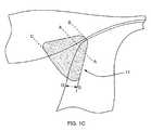
- FIG. 1Cis a schematic representation of a region of ablated tissue in a uterus and tubal ostium.
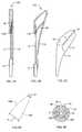
- FIG. 2shows a side view of a tubal occlusion device.
- FIG. 3Ashows a top view of the tubal occlusion device of FIG. 2 with a RF applicator head in a closed position.
- FIG. 3Bshows a top view of the tubal occlusion device of FIG. 2 with the RF applicator head in an open position.
- FIGS. 4A and 4Bshow one embodiment of a structural body of a RF applicator head in closed and open positions respectively.
- FIG. 4Cis a schematic representation of a RF applicator head in an open position.
- FIG. 4Dis a schematic representation of center lines of electrodes of the RF applicator head of FIG. 4C .
- FIG. 4Eis a cross-sectional view of a main body of the tubal occlusion device of FIGS. 2 and 3 .
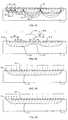
- FIGS. 5A-Dare schematic representations of cross-sectional views showing electrodes in contact with tissue for ablation.
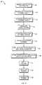
- FIG. 6is a flowchart showing a process for tubal occlusion.
- FIGS. 7A-Dare schematic representations of steps of a process for tubal occlusion.
- FIG. 8is a schematic representation of an alternative embodiment of a structural body of a RF applicator head.
- FIG. 1Aa schematic representation of a uterus 3 is shown, including a uterine cavity 5 surrounded by uterine tissue, namely endometrial tissue 7 a and myometrial tissue 7 b .
- the fallopian tubes 11connect to the uterine cavity 5 at the tubal ostia 9 . Occluding the tubal ostia 9 prevents sperm from entering the fallopian tubes 11 and fertilizing an egg, thereby sterilizing the female.
- a RF (radio frequency) applicator head 2can be introduced transcervically into the uterine cavity and positioned at a tubal ostium 9 .
- Transmitting RF energy through the RF applicator head 2ablates the uterine tissue 7 a , 7 b and tissue within the tubal ostium 9 , as shown schematically by the region 11 in FIG. 1C .
- the healing responseoccludes the tubal ostium 9 and the adjacent portion of the fallopian tube 11 resulting in sterilization.
- the targeted destruction from A-A to Bis approximately 1.5 to 2.5 millimeters
- from A-A to Cis approximately 10 to 20 millimeters
- the depth D-Dis typically approximately 2.0 to 3.5 millimeters.
- FIGS. 2 , 3 A and 3 Bone embodiment of a tubal occlusion device 15 is shown.
- the tubal occlusion device 15includes generally three major components: the RF applicator head 2 , a main body 4 , and a handle 6 .
- FIG. 2shows a side view of the tubal occlusion device 15 and FIGS. 3A and 3B show top views.
- FIG. 3Ashows the tubal occlusion device 15 with the RF applicator head 2 in a closed position within a sheath 32 and
- FIG. 3Bshows the RF applicator head 2 in an open position outside of the sheath 32 .
- the RF applicator head 2includes an electrode carrier 12 mounted to the distal end of the shaft 10 and electrodes 14 formed on the surface of the electrode carrier 12 .
- An RF generator 16can be electrically connected to the electrodes 14 to provide mono-polar or bipolar RF energy to them.
- the main body 4includes a shaft 10 .
- the shaft 10is an elongate member having a hollow interior. In one embodiment, the shaft 10 is approximately 30 centimeters long and has a cross-sectional diameter of approximately 4 millimeters. Extending through the shaft 10 is a suction/insufflation tube 17 having a plurality of holes 17 a formed in its distal end (see FIGS. 4A and 4B ).
- electrode leads 18 a and 18 bextend through the shaft 10 from the distal end 20 to the proximal end 22 of the shaft 10 .
- each of the leads 18 a , 18 bis coupled to a respective one of the electrodes 14 .
- the leads 18 a , 18 bare electrically connected to the RF generator 16 by an electrical connector 21 .
- the leads 18 a , 18 bcarry RF energy from the RF generator 16 to the electrodes 14 .
- Each of the leads 18 a , 18 bis insulated, and the leads 18 a and 18 b can be connected to opposite terminals of the RF generator 16 .
- an electrode pairi.e., one positively charged and one negatively charged electrode or group of electrodes
- Any references herein to a bipolar electroderefer to such an electrode pair.
- the RF applicator head 2can be shaped to approximate the shape of the region to be ablated.
- the embodiment of the RF applicator head 2 shown in FIG. 4Chas a V-shape which can fit within a corner of the uterine cavity 5 and reach into the tubal ostium 9 .
- FIGS. 4A and 4Bshow the RF applicator head 2 without the electrode carrier 12 , thereby revealing the structural body 100 of the RF applicator head 2 .
- a flexible member 19is attached to the distal end of the shaft 10 of the main body and to the distal end of the tube 17 .
- a flexure 22is attached to the tube 17 and to an inner surface of the flexible member 19 .
- the flexure 22In the closed position shown in FIG. 4A , the flexure 22 is compressed within the space formed between the inner surface of the flexible member 19 and the tube 17 , and the shape of the structural body 100 of the RF applicator head 2 is substantially cylindrical.
- the flexure 22 and flexible member 19are made from stainless steel, are approximately 0.012 inches thick and are substantially planar.
- the RF applicator head 2can be deployed into the open position shown in FIG. 4B by moving the tube 17 relative to the shaft 10 .
- the shaft 10is pulled toward the proximal end of the shaft, i.e., away from the RF applicator head 2 .
- Movement of the shaft 10which is connected to the flexible member 19 , causes the flexible member 19 to also move in the same direction, causing the flexure 22 to move laterally away from the tube 17 .
- flexible member 19is deformed outwardly, away from the tube 17 , creating the V-shape at the distal end of the RF applicator head 2 .
- the shape of the distal enddiffers depending on how much the shaft 10 and tube 17 are moved relative to one another.
- the tube 17can be pushed toward the proximal end of the flexible member 19 , i.e., toward the RF applicator head 2 , thereby moving the tube 17 relative to the shaft 10 .
- the relative movementhas the same effect as described above, that is, the flexible member 19 is deformed outwardly, creating a V-shape at the distal end.
- FIG. 4Cshows the distal end of the RF applicator head 2 with the electrode carrier 12 over the structural body.
- the electrode carrier 12can be formed of a fabric that is stretched over the structural body; the fabric is metallized in the regions forming the electrodes 14 .
- the electrodes 14are conductive and can alternate between positive and negative polarity (an electrode pair being a “bipolar electrode” as described above). In the embodiment depicted, there are four electrodes 14 (or 2 bipolar electrodes), two on either face of the electrode carrier 12 .
- a non-conductive insulator 23divides the electrode carrier 12 into the bipolar electrodes 14 .
- the fabricis formed from a composite yarn with a thermoplastic elastomer (TPE) core and multiple polyfilament nylon bundles wound around the TPE as a cover.
- the nylon bundlesare plated with thin conductive metal layers.
- the nylonis metallized, but not the TPE core. This construction facilitates stretching; the nylon windings open up their coils as the TPE core is elongated, without cracking the metallic layer.
- the TPE corefacilitates recovery from the stretched position, pulling the nylon coils back into their initial configuration.
- the electrode carrier 12can be a sack formed of a material that is non-conductive, that is permeable to moisture, and that can be compressed to a smaller volume and subsequently released to its natural size upon elimination of compression.
- materials for the electrode carrier 12include foam, cotton, fabric, or cotton-like material, or any other material having the desired characteristics.
- the electrodes 14can be attached to the outer surface of the electrode carrier 12 , e.g., by deposition or another attachment mechanism.
- the electrodes 14can be made of lengths of silver, gold, platinum, or any other conductive material.
- the electrodes 14can be formed on the electrode carrier 12 by electron beam deposition, or they can be formed into coiled wires and bonded to the electrode carrier 12 using a flexible adhesive. Other means of attaching the electrodes, such as sewing them onto the surface of the electrode carrier 12 , may alternatively be used.
- Depth of destruction of the target tissuecan be contoured to achieve repeatable, predetermined depths.
- Variablessuch as the electrode construction, power applied to the electrodes (power density or power per unit surface area of the electrode), and the tissue impedance at which power is terminated can be used to affect the depth of tissue destruction, as discussed further below.
- lines 19 a and 19 brepresent center lines of the electrodes 14 of the RF applicator head 2 of FIG. 4C , i.e., the spacing.
- the center linesdiverge and are closest at the distal end I and further apart at the proximal end H. The closer the center lines the shallower the depth of destruction. That is, the depth of destruction at the distal end, which during operation is positioned within or closest to the tubal ostium 9 , is least.
- each electrodeis energized at a polarity opposite from that of its neighboring electrodes.
- energy field patternsdesignated 52 , 53 and 54 in FIG. 5A
- the energy patternswill extend more deeply into the tissue. See, for example, pattern 53 which results from energization of electrodes having a non-energized electrode between them, or pattern 54 which results from energization of electrodes having two non-energized electrodes between them.
- the depth of ablationis also effected by the electrode density (i.e., the percentage of the target tissue area which is in contact with active electrode surfaces) and may be regulated by pre-selecting the amount of this active electrode coverage. For example, the depth of ablation is much greater when the active electrode surface covers more than 10% of the target tissue than it is when the active electrode surfaces covers only 1% of the target tissue.
- the electrodes 51 awhich have more active area in contact with the underlying tissue T, produce a region of ablation A 1 that extends more deeply into the tissue T than the ablation region A 2 produced by the low density electrodes 51 b , even though the electrode spacings and widths are the same for the high and low density electrodes.
- electrode widthshaving spacings with less than 1% active electrode surface coverage, and their resultant ablation depth, based on an ablation area of 6 cm 2 and a power of 20-40 watts, are given on the following table:
- the depth of ablationis significantly less when the active electrode surface coverage is decreased.
- a usermay set the RF generator 16 to energize electrodes which will produce a desired electrode spacing and active electrode area.
- alternate electrodesmay be energized as shown in FIG. 5C , with the first three energized electrodes having positive polarity, the second three having negative polarity, etc. All six electrodes together can be referred to as one bipolar electrode.
- FIG. 5Dif greater ablation depth is desired the first five electrodes may be positively energized, and the seventh through eleventh electrodes negatively energized, with the sixth electrode remaining inactivated to provide adequate electrode spacing. Therefore, in one implementation, a user can control which electrodes are energized to produce a desired depth of destruction.
- a controller included in the RF generator 16can monitor the impedance of the tissue at the distal end of the RF applicator head 2 and include an automatic shut-off once a threshold impedance is detected.
- tissueis desiccated by the RF energy, fluid is lost and withdrawn from the region by a vacuum through the tube 17 , which can be connected to suction/insufflation unit 40 via suction/insufflation port 38 ( FIGS. 3A , 3 B).
- the suctiondraws moisture released by tissue undergoing ablation away from the electrode carrier 12 and prevents formation of a low-impedance liquid layer around the electrodes 14 during ablation.
- a threshold impedance levelcan be set that corresponds to a desired depth of ablation.
- the controllershuts off the RF energy, preventing excess destruction of tissue.
- an impedance of the tissue of 50 ohmscan indicate a depth of destruction of approximately 3 to 4 millimeters at the proximal end H and approximately 2.5 millimeters at the distal end I.
- the RF generator 16can be configured such that above the threshold impedance level the RF generator's ability to deliver RF power is greatly reduced, which in effect automatically terminates energy delivery.
- an introducer sheath 32facilitates insertion of the tubal occlusion device 15 into, and removal of the device from, the uterine cavity 5 .
- the sheath 32is a tubular member that is slidable over the shaft 10 .
- the sheath 32is slidable between a distal condition, shown in FIG. 3A , in which the RF applicator head 2 is compressed inside the sheath, and a proximal condition in which the sheath 32 is moved proximally to release the RF applicator head 2 from inside the sheath 32 ( FIG. 3 ).
- the electrode carrier 12By compressing the electrode carrier 12 to a small volume, the RF applicator head 2 can be easily inserted transcervically into the uterine cavity 5 .
- the sheath 32is retracted from the electrode carrier 12 , for example, by moving the distal handle member 34 towards the proximal handle member 37 to slide the sheath 32 in the distal direction.
- Moving the distal handle member 34 toward the proximal handle member 27can also advance the shaft 10 in the proximal direction.
- the movement of the shaft 10 relative to the suction/insufflation tube 17causes the shaft 10 to pull proximally on the flexible member 19 .
- Proximal movement of the flexible member 19in turn pulls the flexure 22 , causing it to move to the opened condition shown in FIG. 3B (see also FIG. 4B ).
- a locking mechanism(not shown) is required to hold the shaft in the fully withdrawn condition to prevent inadvertent closure of the RF applicator head 2 during the ablation procedure.
- the amount by which the flexible member 19 is deformed outwardly from the tube 17can be controlled by manipulating the handle 6 to slide the shaft 10 , proximally or distally.
- the amount by which the shaft 10 is slid relative to the tube 17controls the shape of the flexible member 19 .
- the handle 6can be configured so that the tube 17 can be moved distally relative to the shaft 10 . Distal movement of the tube 17 in turn deforms the flexible member 19 outwardly. The amount by which the flexible member 19 is deformed outwardly from the tube 17 can be controlled by manipulating the handle 6 to slide the tube 17 proximally or distally, and the amount by which the tube 17 moves relative to the shaft 10 controls the shape of the flexible member 19 .
- a flow pathway 36is formed from the RF applicator head 2 to the suction/insufflation port 38 .
- the proximal end of the suction/insufflation tube 17is fluidly coupled to the flow pathway so that gas fluid may be introduced into, or withdrawn from the suction/insufflation tube 17 via the suction/insufflation port 38 .
- suctionmay be applied to the fluid port 38 using a suction/insufflation unit 40 . This causes water vapor within the uterine cavity 5 to pass through the permeable electrode carrier 12 , into the suction/insufflation tube 17 via holes 17 a , through the tube 17 , and through the suction/insufflation unit 40 via the port 38 .
- insufflation gassuch as carbon dioxide
- insufflation gasmay be introduced into the suction/insufflation tube 17 via the port 38 .
- the insufflation gastravels through the tube 17 , through the holes 17 a , and into the uterine cavity 5 through the permeable electrode carrying member 12 .
- lumen 42 , 44 , and 46may be formed in the walls of the introducer sheath 32 as shown in FIG. 4E .
- An optical instrumentcan be used to provide images from within the uterine cavity.
- an imaging conduitsuch as a fiberoptic bundle, extends through lumen 42 and is coupled via a camera cable 43 to a camera 45 . Images taken from the camera may be displayed on a monitor 47 .
- An illumination fiber 50can extend through lumen 44 and couple to an illumination source 49 .
- the optional third lumen 46can be an instrument channel through which surgical instruments may be introduced into the uterine cavity 5 , if necessary.
- one or more of the lumen 42 , 44 , 46can be formed in the walls of the shaft 10 .
- the electrode carrier 12may have additional components inside it that add structural integrity to the electrode carrying means when it is deployed within the body.
- the tubal occlusion device 15is inserted through the vagina and cervix to the internal os 13 at the base of the uterus 3 (step 59 ).
- a gase.g., carbon dioxide
- the tubal occlusion device 15is then advanced into the uterine cavity 5 (step 61 ).
- FIG. 7Ais a schematic representation of what the user may see upon the tubal occlusion device 15 entering the uterine cavity 5 ; the tubal ostium 9 is a relatively small spot in the distance. As the tubal occlusion device 15 advances toward the tubal ostium 9 , the tubal ostium 9 is easier to visualize, as shown in FIG. 7B .
- the distal end of the RF applicator head 2which is still within the sheath 32 , is positioned at the tubal ostium 9 , as depicted in FIG. 7C (step 63 ).
- the sheath 32is withdrawn to expose the electrodes 14 (step 64 ) and the RF applicator head 2 is deployed into the open position (step 65 ), as depicted in FIG. 7D .
- Insufflationis ceased and the uterine cavity 5 is allowed to collapse onto the RF applicator head 2 (step 66 ).
- Vacuumcan be applied to the RF applicator head 2 via the suction/insufflation tube 17 to draw the surrounding tissue into contact with the electrodes 14 (step 67 ).
- the RF generator 16is turned on to provide RF energy to the electrodes 14 (step 68 ).
- the RF energyis ceased once the desired amount of tissue has been ablated (step 69 ). In one implementation, 5.5 watts of RF power is supplied for per square centimeter of electrode surface area until the predetermined impedance threshold is reached, at which point power is terminated.
- the uterine cavity 5can be insufflated a second time, the RF applicator head 2 collapsed into a closed position and the tubal occlusion device 15 rotated approximately 180°.
- the RF applicator head 2can then be positioned at the other tubal ostium 9 and the above procedure repeated to ablate tissue at the other tubal ostium 9 .
- the tubal occlusion device 15is then closed and withdrawn from the patient's body. After ablation, healing and scarring responses of the tissue at the tubal ostia 9 permanently occlude the fallopian tubes 11 , without requiring any foreign objects to remain in the female's body and without any incisions into the female's abdomen.
- the procedureis fast, minimally invasive, and is highly effective at tubal occlusion.
- the structural body 70includes an external hypotube 72 and an internal hypotube 74 .
- the external hypotube 72can be the shaft 10 and the internal hypotube 74 can be the suction/insufflation tube 17 .
- a cage 78is formed over the internal hypotube 74 configured in a V-shape at the distal end 79 that can reach into a tubal ostium 9 .
- the cage 78can be a braided or woven structure made from a memory material, e.g., nitinol.
- the cage 78can be collapsed into a narrow cylindrical configuration by moving the internal hypotube 74 relative to the external hypotube 72 , e.g., by pushing the internal hypotube 74 distally away from the external hypotube 72 .
- the cage 78can fit, for example, within the sheath 32 described above, when the RF applicator head 2 is placed in a closed position.
- An electrode carriersuch as the electrode carrier 12 made from a metallized fabric described above, can be fitted over the structural body 70 , completing the RF applicator head.
Landscapes
- Health & Medical Sciences (AREA)
- Life Sciences & Earth Sciences (AREA)
- Surgery (AREA)
- Engineering & Computer Science (AREA)
- Animal Behavior & Ethology (AREA)
- Veterinary Medicine (AREA)
- Public Health (AREA)
- General Health & Medical Sciences (AREA)
- Biomedical Technology (AREA)
- Heart & Thoracic Surgery (AREA)
- Medical Informatics (AREA)
- Molecular Biology (AREA)
- Nuclear Medicine, Radiotherapy & Molecular Imaging (AREA)
- Reproductive Health (AREA)
- Physics & Mathematics (AREA)
- Otolaryngology (AREA)
- Plasma & Fusion (AREA)
- Gynecology & Obstetrics (AREA)
- Pregnancy & Childbirth (AREA)
- Vascular Medicine (AREA)
- Surgical Instruments (AREA)
Abstract
Description
| ELECTRODE WIDTH SPACING APPROX. DEPTH |
| 1 | mm | 1-2 | mm | 1-3 | mm |
| 1-2.5 | mm | 3-6 | mm | 5-7 | mm |
| 1-4.5 | mm | 8-10 | mm | 8-10 | mm |
| ELECTRODE WIDTH SPACING APPROX. DEPTH |
| 1 | mm | 1-2 | mm | 0.5-1 | mm |
| 1-2.5 | mm | 3-6 | mm | 2-3 | mm |
| 1-4.5 | mm | 8-10 | mm | 2-3 | mm |
Claims (8)
Priority Applications (10)
| Application Number | Priority Date | Filing Date | Title |
|---|---|---|---|
| US11/019,580US7731712B2 (en) | 2004-12-20 | 2004-12-20 | Method and system for transcervical tubal occlusion |
| KR1020077016667AKR20070100306A (en) | 2004-12-20 | 2005-12-05 | Methods and systems for fallopian tube obstruction through the cervix |
| BRPI0519155-6ABRPI0519155A2 (en) | 2004-12-20 | 2005-12-05 | Method and system for occluding a fallopian tube and apparatus for occluding a fallopian tube |
| AU2005319524AAU2005319524A1 (en) | 2004-12-20 | 2005-12-05 | Method and system for transcervical tubal occlusion |
| PCT/US2005/043850WO2006068808A1 (en) | 2004-12-20 | 2005-12-05 | Method and system for transcervical tubal occlusion |
| EP05825814AEP1830731A1 (en) | 2004-12-20 | 2005-12-05 | Method and system for transcervical tubal occlusion |
| MX2007007443AMX2007007443A (en) | 2004-12-20 | 2005-12-05 | Method and system for transcervical tubal occlusion. |
| CA002591545ACA2591545A1 (en) | 2004-12-20 | 2005-12-05 | Method and system for transcervical tubal occlusion |
| CN2005800484403ACN101123924B (en) | 2004-12-20 | 2005-12-05 | System for transcervical tubal occlusion |
| US12/784,702US20100228245A1 (en) | 2004-12-20 | 2010-05-21 | Method and System for Transcervical Tubal Occlusion |
Applications Claiming Priority (1)
| Application Number | Priority Date | Filing Date | Title |
|---|---|---|---|
| US11/019,580US7731712B2 (en) | 2004-12-20 | 2004-12-20 | Method and system for transcervical tubal occlusion |
Related Child Applications (1)
| Application Number | Title | Priority Date | Filing Date |
|---|---|---|---|
| US12/784,702DivisionUS20100228245A1 (en) | 2004-12-20 | 2010-05-21 | Method and System for Transcervical Tubal Occlusion |
Publications (2)
| Publication Number | Publication Date |
|---|---|
| US20060135956A1 US20060135956A1 (en) | 2006-06-22 |
| US7731712B2true US7731712B2 (en) | 2010-06-08 |
Family
ID=35825321
Family Applications (2)
| Application Number | Title | Priority Date | Filing Date |
|---|---|---|---|
| US11/019,580Expired - Fee RelatedUS7731712B2 (en) | 2004-12-20 | 2004-12-20 | Method and system for transcervical tubal occlusion |
| US12/784,702AbandonedUS20100228245A1 (en) | 2004-12-20 | 2010-05-21 | Method and System for Transcervical Tubal Occlusion |
Family Applications After (1)
| Application Number | Title | Priority Date | Filing Date |
|---|---|---|---|
| US12/784,702AbandonedUS20100228245A1 (en) | 2004-12-20 | 2010-05-21 | Method and System for Transcervical Tubal Occlusion |
Country Status (9)
| Country | Link |
|---|---|
| US (2) | US7731712B2 (en) |
| EP (1) | EP1830731A1 (en) |
| KR (1) | KR20070100306A (en) |
| CN (1) | CN101123924B (en) |
| AU (1) | AU2005319524A1 (en) |
| BR (1) | BRPI0519155A2 (en) |
| CA (1) | CA2591545A1 (en) |
| MX (1) | MX2007007443A (en) |
| WO (1) | WO2006068808A1 (en) |
Cited By (5)
| Publication number | Priority date | Publication date | Assignee | Title |
|---|---|---|---|---|
| US8486060B2 (en) | 2006-09-18 | 2013-07-16 | Cytyc Corporation | Power ramping during RF ablation |
| US8506563B2 (en) | 1996-04-12 | 2013-08-13 | Cytyc Surgical Products | Moisture transport system for contact electrocoagulation |
| US8551082B2 (en) | 1998-05-08 | 2013-10-08 | Cytyc Surgical Products | Radio-frequency generator for powering an ablation device |
| US9655557B2 (en) | 2011-02-04 | 2017-05-23 | Minerva Surgical, Inc. | Methods and systems for evaluating the integrity of a uterine cavity |
| US11246644B2 (en) | 2018-04-05 | 2022-02-15 | Covidien Lp | Surface ablation using bipolar RF electrode |
Families Citing this family (37)
| Publication number | Priority date | Publication date | Assignee | Title |
|---|---|---|---|---|
| US8137256B2 (en)* | 2005-12-16 | 2012-03-20 | Portola Medical, Inc. | Brachytherapy apparatus |
| US20070270627A1 (en)* | 2005-12-16 | 2007-11-22 | North American Scientific | Brachytherapy apparatus for asymmetrical body cavities |
| GB2441306A (en)* | 2006-09-01 | 2008-03-05 | Microsulis Ltd | Endometrial treatment device with stepper actuator, angular sweep rate sensor and bending deflection sensor |
| US20080071269A1 (en)* | 2006-09-18 | 2008-03-20 | Cytyc Corporation | Curved Endoscopic Medical Device |
| WO2008058089A2 (en)* | 2006-11-03 | 2008-05-15 | North American Scientific, Inc. | Brachytherapy device having seed tubes with individually-settable tissue spacings |
| US7846160B2 (en)* | 2006-12-21 | 2010-12-07 | Cytyc Corporation | Method and apparatus for sterilization |
| WO2009009443A1 (en) | 2007-07-06 | 2009-01-15 | Barrx Medical, Inc. | Method and apparatus for gastrointestinal tract ablation to achieve loss of persistent and/or recurrent excess body weight following a weight-loss operation |
| US20090318914A1 (en)* | 2008-06-18 | 2009-12-24 | Utley David S | System and method for ablational treatment of uterine cervical neoplasia |
| US9662163B2 (en) | 2008-10-21 | 2017-05-30 | Hermes Innovations Llc | Endometrial ablation devices and systems |
| US8382753B2 (en) | 2008-10-21 | 2013-02-26 | Hermes Innovations, LLC | Tissue ablation methods |
| US8500732B2 (en) | 2008-10-21 | 2013-08-06 | Hermes Innovations Llc | Endometrial ablation devices and systems |
| US8540708B2 (en) | 2008-10-21 | 2013-09-24 | Hermes Innovations Llc | Endometrial ablation method |
| US8197476B2 (en) | 2008-10-21 | 2012-06-12 | Hermes Innovations Llc | Tissue ablation systems |
| US8197477B2 (en) | 2008-10-21 | 2012-06-12 | Hermes Innovations Llc | Tissue ablation methods |
| US8821486B2 (en) | 2009-11-13 | 2014-09-02 | Hermes Innovations, LLC | Tissue ablation systems and methods |
| US20100217250A1 (en)* | 2009-02-24 | 2010-08-26 | Sierra Surgical Technologies | Methods and systems for controlled thermal tissue |
| CN101822566A (en)* | 2009-03-05 | 2010-09-08 | 上海家宝医学保健科技有限公司 | Multifunctional disposable visible suction apparatus for uterine cavity tissues |
| US8715278B2 (en) | 2009-11-11 | 2014-05-06 | Minerva Surgical, Inc. | System for endometrial ablation utilizing radio frequency |
| US11896282B2 (en) | 2009-11-13 | 2024-02-13 | Hermes Innovations Llc | Tissue ablation systems and method |
| US9289257B2 (en) | 2009-11-13 | 2016-03-22 | Minerva Surgical, Inc. | Methods and systems for endometrial ablation utilizing radio frequency |
| US8529562B2 (en) | 2009-11-13 | 2013-09-10 | Minerva Surgical, Inc | Systems and methods for endometrial ablation |
| US8956348B2 (en) | 2010-07-21 | 2015-02-17 | Minerva Surgical, Inc. | Methods and systems for endometrial ablation |
| US9510897B2 (en) | 2010-11-05 | 2016-12-06 | Hermes Innovations Llc | RF-electrode surface and method of fabrication |
| CN102309360B (en)* | 2011-08-01 | 2012-12-26 | 李怀兰 | Fallopian-tube sounding instrument |
| US9901394B2 (en) | 2013-04-04 | 2018-02-27 | Hermes Innovations Llc | Medical ablation system and method of making |
| US9649125B2 (en) | 2013-10-15 | 2017-05-16 | Hermes Innovations Llc | Laparoscopic device |
| ES2727963T3 (en)* | 2014-07-22 | 2019-10-21 | Eximis Surgical Llc | Large volume tissue reduction and extraction system |
| US10492856B2 (en) | 2015-01-26 | 2019-12-03 | Hermes Innovations Llc | Surgical fluid management system and method of use |
| CN107708591B (en) | 2015-04-29 | 2020-09-29 | 席勒斯科技有限公司 | Medical ablation device and method of use |
| US10052149B2 (en) | 2016-01-20 | 2018-08-21 | RELIGN Corporation | Arthroscopic devices and methods |
| CN109561899A (en) | 2016-04-22 | 2019-04-02 | 锐凌公司 | Arthroscope device and method |
| US10772676B2 (en)* | 2016-05-31 | 2020-09-15 | Kogent Surgical, LLC | Microsurgical bipolar forceps |
| CN109661209A (en) | 2016-07-01 | 2019-04-19 | 锐凌公司 | Arthroscope device and method |
| WO2019059914A2 (en)* | 2017-09-21 | 2019-03-28 | Park Sam Boong | Methods for manufacturing electrosurgical fabrics |
| US11554214B2 (en) | 2019-06-26 | 2023-01-17 | Meditrina, Inc. | Fluid management system |
| US11553958B2 (en) | 2020-02-07 | 2023-01-17 | Covidien Lp | Electrosurgical device for cutting tissue |
| WO2024015467A1 (en)* | 2022-07-12 | 2024-01-18 | Oregon Health & Science University | Methods and systems for trans-cervical delivery of agents |
Citations (176)
| Publication number | Priority date | Publication date | Assignee | Title |
|---|---|---|---|---|
| US552832A (en) | 1896-01-07 | Instrument for treatment of strictures by electrolysis | ||
| US725731A (en) | 1901-08-09 | 1903-04-21 | Samuel H Linn | Cataphoric electrode. |
| DE384246C (en) | 1922-03-04 | 1923-10-31 | Oskar Gleichmann Dr | Medical device for the treatment of female uterine gonorrhea |
| US1620929A (en) | 1925-02-05 | 1927-03-15 | George W Wallerich | Heat-therapy method and means |
| US1827306A (en) | 1925-09-14 | 1931-10-13 | Fischer & Co H G | Electrode |
| FR774550A (en) | 1933-06-16 | 1934-12-08 | Electric device for heat treatment of gonorrhea | |
| US2190383A (en) | 1936-08-29 | 1940-02-13 | Louis B Newman | Therapeutic apparatus |
| US2347195A (en) | 1942-05-25 | 1944-04-25 | Universal Oil Prod Co | Means of contacting fluid reactants |
| US2466042A (en) | 1947-08-26 | 1949-04-05 | Walter J Reich | Internal heat-treatment device |
| US3228398A (en) | 1963-03-12 | 1966-01-11 | Washington Ethical Labs Inc | Vaginal cleanser |
| US3324855A (en) | 1965-01-12 | 1967-06-13 | Henry J Heimlich | Surgical sponge stick |
| US3645265A (en) | 1969-06-25 | 1972-02-29 | Gregory Majzlin | Intrauterine cauterizing device |
| DE2222820A1 (en) | 1972-05-10 | 1973-11-22 | Delma Elektro Med App | ELECTRODE FOR SURFACE COAGULATION |
| US3840016A (en) | 1972-03-10 | 1974-10-08 | H Lindemann | Electrocoagulation-bougie for the intrauterine tube sterilization |
| US3845771A (en) | 1973-04-24 | 1974-11-05 | W Vise | Electrosurgical glove |
| US3858586A (en) | 1971-03-11 | 1975-01-07 | Martin Lessen | Surgical method and electrode therefor |
| US3877464A (en) | 1972-06-07 | 1975-04-15 | Andrew R Vermes | Intra-uterine biopsy apparatus |
| US3924628A (en) | 1972-12-01 | 1975-12-09 | William Droegemueller | Cyrogenic bladder for necrosing tissue cells |
| US3948270A (en) | 1974-10-15 | 1976-04-06 | Hasson Harrith M | Uterine cannula |
| US3967625A (en) | 1973-07-30 | 1976-07-06 | In Bae Yoon | Device for sterilizing the human female or male by ligation |
| US3971378A (en) | 1974-12-20 | 1976-07-27 | Ortho Pharmaceutical Corporation | Expansible tampon |
| US4022215A (en) | 1973-12-10 | 1977-05-10 | Benson Jerrel W | Cryosurgical system |
| US4057063A (en) | 1975-04-11 | 1977-11-08 | U.S. Philips Corporation | Device for sterilization by transuterine tube coagulation |
| US4158050A (en) | 1978-06-15 | 1979-06-12 | International Fertility Research Programme | Method for effecting female sterilization without surgery |
| US4185618A (en) | 1976-01-05 | 1980-01-29 | Population Research, Inc. | Promotion of fibrous tissue growth in fallopian tubes for female sterilization |
| US4233025A (en) | 1979-03-08 | 1980-11-11 | Larson William A | Hollow cotton roll |
| EP0056178A1 (en) | 1981-01-12 | 1982-07-21 | Mitsubishi Rayon Co., Ltd. | Electrode for living bodies |
| US4359454A (en) | 1980-12-16 | 1982-11-16 | World Health Organization | Method and composition containing MCA for female sterilization |
| US4380238A (en) | 1981-08-21 | 1983-04-19 | Institute Straunann | Disposable applicator for mini-laparotomy using a clip method |
| US4415288A (en) | 1981-03-09 | 1983-11-15 | Whitman Medical Corporation | Liquid dispensing device with cartridge-rupturing member |
| US4449528A (en) | 1980-03-20 | 1984-05-22 | University Of Washington | Fast pulse thermal cautery probe and method |
| US4465072A (en) | 1983-02-22 | 1984-08-14 | Taheri Syde A | Needle catheter |
| US4492231A (en) | 1982-09-17 | 1985-01-08 | Auth David C | Non-sticking electrocautery system and forceps |
| US4532924A (en) | 1980-05-13 | 1985-08-06 | American Hospital Supply Corporation | Multipolar electrosurgical device and method |
| US4568326A (en) | 1982-01-27 | 1986-02-04 | Avvari Rangaswamy | Epistaxis sponge |
| US4582057A (en) | 1981-07-20 | 1986-04-15 | Regents Of The University Of Washington | Fast pulse thermal cautery probe |
| US4601698A (en) | 1984-09-17 | 1986-07-22 | Moulding Jr Thomas S | Method of and instrument for injecting a fluid into a uterine cavity and for dispersing the fluid into the fallopian tubes |
| US4606336A (en) | 1984-11-23 | 1986-08-19 | Zeluff James W | Method and apparatus for non-surgically sterilizing female reproductive organs |
| US4628924A (en) | 1983-01-20 | 1986-12-16 | Hugo Cimber | Intrauterine contraceptive device |
| US4662383A (en) | 1982-09-27 | 1987-05-05 | Kureha Kagaku Kogyo Kabushiki Kaisha | Endotract antenna device for hyperthermia |
| US4676258A (en) | 1983-01-24 | 1987-06-30 | Kureha Kagaku Kogyo Kabushiki Kaisha | Device for hyperthermia |
| US4682809A (en)* | 1984-12-05 | 1987-07-28 | Heinrich Huss | Car body |
| US4691703A (en) | 1986-04-25 | 1987-09-08 | Board Of Regents, University Of Washington | Thermal cautery system |
| US4765331A (en) | 1987-02-10 | 1988-08-23 | Circon Corporation | Electrosurgical device with treatment arc of less than 360 degrees |
| US4788966A (en) | 1987-05-14 | 1988-12-06 | Inbae Yoon | Plug for use in a reversible sterilization procedure |
| US4832048A (en) | 1987-10-29 | 1989-05-23 | Cordis Corporation | Suction ablation catheter |
| US4865047A (en) | 1988-06-30 | 1989-09-12 | City Of Hope | Hyperthermia applicator |
| US4869268A (en) | 1987-05-14 | 1989-09-26 | Inbae Yoon | Multi-functional instruments and stretchable ligating and occluding devices |
| US4946440A (en) | 1988-10-05 | 1990-08-07 | Hall John E | Evertible membrane catheter and method of use |
| US4949718A (en) | 1988-09-09 | 1990-08-21 | Gynelab Products | Intrauterine cauterizing apparatus |
| US4955377A (en) | 1988-10-28 | 1990-09-11 | Lennox Charles D | Device and method for heating tissue in a patient's body |
| US4960133A (en) | 1988-11-21 | 1990-10-02 | Brunswick Manufacturing Co., Inc. | Esophageal electrode |
| US4961435A (en) | 1987-10-28 | 1990-10-09 | Kureha Kagaku Kogyo Kabushiki Kaishi | High-frequency capacitive heating electrode device |
| US4979948A (en) | 1989-04-13 | 1990-12-25 | Purdue Research Foundation | Method and apparatus for thermally destroying a layer of an organ |
| US4981465A (en) | 1985-01-15 | 1991-01-01 | Coloplast A/S | Disposable closure means for an artificial ostomy opening or an incontinent natural anus |
| US4983177A (en) | 1990-01-03 | 1991-01-08 | Wolf Gerald L | Method and apparatus for reversibly occluding a biological tube |
| US5026379A (en) | 1989-12-05 | 1991-06-25 | Inbae Yoon | Multi-functional instruments and stretchable ligating and occluding devices |
| DE4001086A1 (en) | 1990-01-17 | 1991-07-18 | Weikl Andreas | Medical treatment catheter widening constricted vessels - has two expandable balloons spaced in axial direction with heat conductive piece between them |
| US5047028A (en) | 1989-05-12 | 1991-09-10 | Quinghua Qian | Method for inducing thrombosis in blood vessels |
| US5057106A (en) | 1986-02-27 | 1991-10-15 | Kasevich Associates, Inc. | Microwave balloon angioplasty |
| US5065751A (en) | 1990-01-03 | 1991-11-19 | Wolf Gerald L | Method and apparatus for reversibly occluding a biological tube |
| US5078717A (en) | 1989-04-13 | 1992-01-07 | Everest Medical Corporation | Ablation catheter with selectively deployable electrodes |
| US5084044A (en) | 1989-07-14 | 1992-01-28 | Ciron Corporation | Apparatus for endometrial ablation and method of using same |
| US5147353A (en) | 1990-03-23 | 1992-09-15 | Myriadlase, Inc. | Medical method for applying high energy light and heat for gynecological sterilization procedures |
| US5159925A (en) | 1988-09-09 | 1992-11-03 | Gynelab, Inc. | Cauterizing apparatus and method for laparoscopic cholecystostomy, gallbladder ablation and treatment of benign prostate hypertrophy |
| US5186181A (en) | 1990-07-27 | 1993-02-16 | Cafiero Franconi | Radio frequency thermotherapy |
| US5188122A (en) | 1989-06-20 | 1993-02-23 | Rocket Of London Limited | Electromagnetic energy generation method |
| US5188602A (en) | 1990-07-12 | 1993-02-23 | Interventional Thermodynamics, Inc. | Method and device for delivering heat to hollow body organs |
| US5217473A (en) | 1989-12-05 | 1993-06-08 | Inbae Yoon | Multi-functional instruments and stretchable ligating and occluding devices |
| US5226908A (en) | 1989-12-05 | 1993-07-13 | Inbae Yoon | Multi-functional instruments and stretchable ligating and occluding devices |
| US5242437A (en) | 1988-06-10 | 1993-09-07 | Trimedyne Laser Systems, Inc. | Medical device applying localized high intensity light and heat, particularly for destruction of the endometrium |
| US5248312A (en) | 1992-06-01 | 1993-09-28 | Sensor Electronics, Inc. | Liquid metal-filled balloon |
| US5263585A (en) | 1992-05-07 | 1993-11-23 | Myriadlase, Inc. | Package for an elongated flexible fiber |
| US5277201A (en) | 1992-05-01 | 1994-01-11 | Vesta Medical, Inc. | Endometrial ablation apparatus and method |
| EP0584930A1 (en) | 1992-07-31 | 1994-03-02 | Spembly Medical Limited | Cryosurgical ablation |
| US5308327A (en) | 1991-11-25 | 1994-05-03 | Advanced Surgical Inc. | Self-deployed inflatable retractor |
| US5318532A (en) | 1989-10-03 | 1994-06-07 | C. R. Bard, Inc. | Multilumen catheter with variable cross-section lumens |
| US5322507A (en) | 1992-08-11 | 1994-06-21 | Myriadlase, Inc. | Endoscope for treatment of prostate |
| US5334193A (en) | 1992-11-13 | 1994-08-02 | American Cardiac Ablation Co., Inc. | Fluid cooled ablation catheter |
| US5354295A (en) | 1990-03-13 | 1994-10-11 | Target Therapeutics, Inc. | In an endovascular electrolytically detachable wire and tip for the formation of thrombus in arteries, veins, aneurysms, vascular malformations and arteriovenous fistulas |
| US5364393A (en) | 1990-07-02 | 1994-11-15 | Heart Technology, Inc. | Tissue dissipative recanalization catheter |
| US5370649A (en) | 1991-08-16 | 1994-12-06 | Myriadlase, Inc. | Laterally reflecting tip for laser transmitting fiber |
| US5374283A (en) | 1993-12-01 | 1994-12-20 | Flick; A. Bart | Electrical therapeutic apparatus |
| US5374261A (en) | 1990-07-24 | 1994-12-20 | Yoon; Inbae | Multifunctional devices for use in endoscopic surgical procedures and methods-therefor |
| US5383917A (en) | 1991-07-05 | 1995-01-24 | Jawahar M. Desai | Device and method for multi-phase radio-frequency ablation |
| US5395311A (en) | 1990-05-14 | 1995-03-07 | Andrews; Winston A. | Atherectomy catheter |
| US5405322A (en) | 1993-08-12 | 1995-04-11 | Boston Scientific Corporation | Method for treating aneurysms with a thermal source |
| US5433708A (en) | 1991-05-17 | 1995-07-18 | Innerdyne, Inc. | Method and device for thermal ablation having improved heat transfer |
| US5437629A (en) | 1994-04-14 | 1995-08-01 | Bei Medical Systems | Fluid delivery system for hysteroscopic endometrial ablation |
| US5443470A (en) | 1992-05-01 | 1995-08-22 | Vesta Medical, Inc. | Method and apparatus for endometrial ablation |
| US5451204A (en) | 1988-07-22 | 1995-09-19 | Yoon; Inbae | Multifunctional devices for endoscopic surgical procedures |
| US5474089A (en) | 1991-06-26 | 1995-12-12 | The United States Of America As Represented By The Secretary Of The Department Of Health And Human Services | Method and device for reversible sterilization |
| US5505730A (en) | 1994-06-24 | 1996-04-09 | Stuart D. Edwards | Thin layer ablation apparatus |
| US5507744A (en)* | 1992-04-23 | 1996-04-16 | Scimed Life Systems, Inc. | Apparatus and method for sealing vascular punctures |
| US5507743A (en) | 1993-11-08 | 1996-04-16 | Zomed International | Coiled RF electrode treatment apparatus |
| US5514091A (en) | 1988-07-22 | 1996-05-07 | Yoon; Inbae | Expandable multifunctional manipulating instruments for various medical procedures |
| US5562703A (en) | 1994-06-14 | 1996-10-08 | Desai; Ashvin H. | Endoscopic surgical instrument |
| US5562720A (en) | 1992-05-01 | 1996-10-08 | Vesta Medical, Inc. | Bipolar/monopolar endometrial ablation device and method |
| US5588961A (en) | 1994-06-14 | 1996-12-31 | Cordis Corporation | Electro-osmotic infusion catheter |
| US5609598A (en) | 1994-12-30 | 1997-03-11 | Vnus Medical Technologies, Inc. | Method and apparatus for minimally invasive treatment of chronic venous insufficiency |
| US5613950A (en) | 1988-07-22 | 1997-03-25 | Yoon; Inbae | Multifunctional manipulating instrument for various surgical procedures |
| US5626576A (en)* | 1989-01-06 | 1997-05-06 | Advanced Coronary Intervention, Inc. | Electrosurgical catheter for resolving atherosclerotic plaque by radio frequency sparking |
| US5667520A (en) | 1990-03-02 | 1997-09-16 | General Surgical Innovations, Inc. | Method of performing balloon dissection |
| US5697882A (en) | 1992-01-07 | 1997-12-16 | Arthrocare Corporation | System and method for electrosurgical cutting and ablation |
| US5702438A (en) | 1995-06-08 | 1997-12-30 | Avitall; Boaz | Expandable recording and ablation catheter system |
| US5709224A (en)* | 1995-06-07 | 1998-01-20 | Radiotherapeutics Corporation | Method and device for permanent vessel occlusion |
| US5716343A (en) | 1989-06-16 | 1998-02-10 | Science Incorporated | Fluid delivery apparatus |
| US5730136A (en) | 1995-03-14 | 1998-03-24 | Vnus Medical Technologies, Inc. | Venous pump efficiency test system and method |
| US5769880A (en) | 1996-04-12 | 1998-06-23 | Novacept | Moisture transport system for contact electrocoagulation |
| US5779698A (en) | 1989-01-18 | 1998-07-14 | Applied Medical Resources Corporation | Angioplasty catheter system and method for making same |
| US5797903A (en) | 1996-04-12 | 1998-08-25 | Ep Technologies, Inc. | Tissue heating and ablation systems and methods using porous electrode structures with electrically conductive surfaces |
| US5800482A (en) | 1996-03-06 | 1998-09-01 | Cardiac Pathways Corporation | Apparatus and method for linear lesion ablation |
| US5846238A (en) | 1996-01-19 | 1998-12-08 | Ep Technologies, Inc. | Expandable-collapsible electrode structures with distal end steering or manipulation |
| US5879348A (en) | 1996-04-12 | 1999-03-09 | Ep Technologies, Inc. | Electrode structures formed from flexible, porous, or woven materials |
| US5885601A (en) | 1996-04-05 | 1999-03-23 | Family Health International | Use of macrolide antibiotics for nonsurgical female sterilization and endometrial ablation |
| US5888198A (en) | 1992-01-07 | 1999-03-30 | Arthrocare Corporation | Electrosurgical system for resection and ablation of tissue in electrically conductive fluids |
| US5891136A (en) | 1996-01-19 | 1999-04-06 | Ep Technologies, Inc. | Expandable-collapsible mesh electrode structures |
| US5891134A (en) | 1996-09-24 | 1999-04-06 | Goble; Colin | System and method for applying thermal energy to tissue |
| US5897551A (en) | 1990-03-23 | 1999-04-27 | Myriadlase, Inc. | Medical device for applying high energy light and heat for gynecological sterilization procedures |
| US5897553A (en) | 1995-11-02 | 1999-04-27 | Medtronic, Inc. | Ball point fluid-assisted electrocautery device |
| US5935137A (en) | 1997-07-18 | 1999-08-10 | Gynecare, Inc. | Tubular fallopian sterilization device |
| US5938660A (en) | 1997-06-27 | 1999-08-17 | Daig Corporation | Process and device for the treatment of atrial arrhythmia |
| US5954717A (en) | 1997-09-25 | 1999-09-21 | Radiotherapeutics Corporation | Method and system for heating solid tissue |
| US5954715A (en)* | 1997-06-05 | 1999-09-21 | Adiana, Inc. | Method and apparatus for tubal occlusion |
| US6002968A (en) | 1994-06-24 | 1999-12-14 | Vidacare, Inc. | Uterine treatment apparatus |
| US6014589A (en) | 1997-11-12 | 2000-01-11 | Vnus Medical Technologies, Inc. | Catheter having expandable electrodes and adjustable stent |
| US6033397A (en) | 1996-03-05 | 2000-03-07 | Vnus Medical Technologies, Inc. | Method and apparatus for treating esophageal varices |
| US6036687A (en) | 1996-03-05 | 2000-03-14 | Vnus Medical Technologies, Inc. | Method and apparatus for treating venous insufficiency |
| US6077257A (en) | 1996-05-06 | 2000-06-20 | Vidacare, Inc. | Ablation of rectal and other internal body structures |
| US6096052A (en) | 1998-07-08 | 2000-08-01 | Ovion, Inc. | Occluding device and method of use |
| US6117101A (en) | 1997-07-08 | 2000-09-12 | The Regents Of The University Of California | Circumferential ablation device assembly |
| US6123702A (en) | 1998-09-10 | 2000-09-26 | Scimed Life Systems, Inc. | Systems and methods for controlling power in an electrosurgical probe |
| US6135997A (en) | 1996-03-05 | 2000-10-24 | Vnus Medical Technologies, Inc. | Method for treating hemorrhoids |
| US6152899A (en) | 1996-03-05 | 2000-11-28 | Vnus Medical Technologies, Inc. | Expandable catheter having improved electrode design, and method for applying energy |
| US6159207A (en) | 1997-07-31 | 2000-12-12 | Yoon; Inbae | Protected ablation method and apparatus |
| US6165172A (en) | 1997-09-11 | 2000-12-26 | Vnus Medical Technologies, Inc. | Expandable vein ligator catheter and method of use |
| US6179832B1 (en) | 1997-09-11 | 2001-01-30 | Vnus Medical Technologies, Inc. | Expandable catheter having two sets of electrodes |
| US6183468B1 (en) | 1998-09-10 | 2001-02-06 | Scimed Life Systems, Inc. | Systems and methods for controlling power in an electrosurgical probe |
| US6231496B1 (en) | 1999-07-07 | 2001-05-15 | Peter J. Wilk | Medical treatment method |
| US6231507B1 (en) | 1997-06-02 | 2001-05-15 | Vnus Medical Technologies, Inc. | Pressure tourniquet with ultrasound window and method of use |
| US6234178B1 (en) | 1996-01-09 | 2001-05-22 | Gyrus Medical Limited | Electrosurgical instrument |
| US6238393B1 (en) | 1998-07-07 | 2001-05-29 | Medtronic, Inc. | Method and apparatus for creating a bi-polar virtual electrode used for the ablation of tissue |
| US6245090B1 (en) | 1997-11-07 | 2001-06-12 | Salviac Limited | Transcatheter occluding implant |
| US6245065B1 (en) | 1998-09-10 | 2001-06-12 | Scimed Life Systems, Inc. | Systems and methods for controlling power in an electrosurgical probe |
| US6254601B1 (en) | 1998-12-08 | 2001-07-03 | Hysterx, Inc. | Methods for occlusion of the uterine arteries |
| US6258084B1 (en) | 1997-09-11 | 2001-07-10 | Vnus Medical Technologies, Inc. | Method for applying energy to biological tissue including the use of tumescent tissue compression |
| US6293942B1 (en) | 1995-06-23 | 2001-09-25 | Gyrus Medical Limited | Electrosurgical generator method |
| US6296639B1 (en) | 1999-02-12 | 2001-10-02 | Novacept | Apparatuses and methods for interstitial tissue removal |
| US6309384B1 (en) | 1999-02-01 | 2001-10-30 | Adiana, Inc. | Method and apparatus for tubal occlusion |
| US6315776B1 (en) | 1994-06-24 | 2001-11-13 | Vidacare, Inc. | Thin layer ablation apparatus |
| US20010041900A1 (en) | 1999-12-21 | 2001-11-15 | Ovion, Inc. | Occluding device and method of use |
| US6322559B1 (en) | 1998-07-06 | 2001-11-27 | Vnus Medical Technologies, Inc. | Electrode catheter having coil structure |
| US6325798B1 (en)* | 1998-02-19 | 2001-12-04 | Curon Medical, Inc. | Vacuum-assisted systems and methods for treating sphincters and adjoining tissue regions |
| US20020022870A1 (en)* | 1996-04-12 | 2002-02-21 | Csaba Truckai | Moisture transport system for contact electrocoagulation |
| US20020029051A1 (en) | 1996-12-18 | 2002-03-07 | Edward J. Lynch | Occluding device and method of use |
| US6369465B1 (en) | 1998-05-22 | 2002-04-09 | Scimed Life Systems, Inc. | Power supply for use in electrophysiological apparatus employing high-voltage pulses to render tissue temporarily unresponsive |
| US6395012B1 (en) | 2000-05-04 | 2002-05-28 | Inbae Yoon | Apparatus and method for delivering and deploying an expandable body member in a uterine cavity |
| US6398780B1 (en) | 1997-09-11 | 2002-06-04 | Vnus Medical Technologies, Inc. | Expandable vein ligator catheter and method of use |
| US20020072499A1 (en) | 1999-03-22 | 2002-06-13 | Histatek, Inc. | Treatment with small peptides to effect antifibrotic activity |
| US6428537B1 (en) | 1998-05-22 | 2002-08-06 | Scimed Life Systems, Inc. | Electrophysiological treatment methods and apparatus employing high voltage pulse to render tissue temporarily unresponsive |
| US6475213B1 (en) | 1996-01-19 | 2002-11-05 | Ep Technologies, Inc. | Method of ablating body tissue |
| US6485500B1 (en) | 2000-03-21 | 2002-11-26 | Advanced Cardiovascular Systems, Inc. | Emboli protection system |
| US6508815B1 (en) | 1998-05-08 | 2003-01-21 | Novacept | Radio-frequency generator for powering an ablation device |
| US6554780B1 (en)* | 1999-11-10 | 2003-04-29 | Novacept | System and method for detecting perforations in a body cavity |
| US20030093101A1 (en) | 2001-11-13 | 2003-05-15 | O'heeron Peter T. | Trocar |
| US6587731B1 (en)* | 1996-11-08 | 2003-07-01 | Surx, Inc. | Devices, methods, and systems for shrinking tissues |
| US20030130711A1 (en) | 2001-09-28 | 2003-07-10 | Pearson Robert M. | Impedance controlled tissue ablation apparatus and method |
| US6679269B2 (en) | 1995-07-28 | 2004-01-20 | Scimed Life Systems, Inc. | Systems and methods for conducting electrophysiological testing using high-voltage energy pulses to stun tissue |
| EP1400182A1 (en) | 2002-04-19 | 2004-03-24 | Ya-Man Ltd | Glove with electrode |
| US6712815B2 (en) | 2001-01-16 | 2004-03-30 | Novacept, Inc. | Apparatus and method for treating venous reflux |
| US20040118166A1 (en) | 2002-12-19 | 2004-06-24 | King's Metal Fiber Technologies Co., Ltd. | Wearable electrode apparatus and manufacture thereof |
| US20040172051A1 (en) | 2003-02-28 | 2004-09-02 | Sundaram Ravikumar | Method and apparatus for tubal occlusion |
| US20050085880A1 (en) | 1996-04-12 | 2005-04-21 | Csaba Truckai | Moisture transport system for contact electrocoagulation |
| US20050187561A1 (en)* | 2004-02-25 | 2005-08-25 | Femasys, Inc. | Methods and devices for conduit occlusion |
| US6939348B2 (en)* | 2003-03-27 | 2005-09-06 | Cierra, Inc. | Energy based devices and methods for treatment of patent foramen ovale |
| US20050273094A1 (en)* | 2004-06-07 | 2005-12-08 | Ryan Thomas P | Tubal sterilization device having sesquipolar electrodes and method for performing sterilization using the same |
Family Cites Families (6)
| Publication number | Priority date | Publication date | Assignee | Title |
|---|---|---|---|---|
| US5095917A (en)* | 1990-01-19 | 1992-03-17 | Vancaillie Thierry G | Transuterine sterilization apparatus and method |
| US5122137A (en)* | 1990-04-27 | 1992-06-16 | Boston Scientific Corporation | Temperature controlled rf coagulation |
| US6066139A (en)* | 1996-05-14 | 2000-05-23 | Sherwood Services Ag | Apparatus and method for sterilization and embolization |
| US5893848A (en)* | 1996-10-24 | 1999-04-13 | Plc Medical Systems, Inc. | Gauging system for monitoring channel depth in percutaneous endocardial revascularization |
| US6514249B1 (en)* | 1997-07-08 | 2003-02-04 | Atrionix, Inc. | Positioning system and method for orienting an ablation element within a pulmonary vein ostium |
| US20020068934A1 (en)* | 1999-06-23 | 2002-06-06 | Edwards Stuart D. | Thin layer ablation apparatus |
- 2004
- 2004-12-20USUS11/019,580patent/US7731712B2/ennot_activeExpired - Fee Related
- 2005
- 2005-12-05BRBRPI0519155-6Apatent/BRPI0519155A2/ennot_activeIP Right Cessation
- 2005-12-05MXMX2007007443Apatent/MX2007007443A/ennot_activeApplication Discontinuation
- 2005-12-05AUAU2005319524Apatent/AU2005319524A1/ennot_activeAbandoned
- 2005-12-05WOPCT/US2005/043850patent/WO2006068808A1/enactiveApplication Filing
- 2005-12-05CNCN2005800484403Apatent/CN101123924B/ennot_activeExpired - Fee Related
- 2005-12-05CACA002591545Apatent/CA2591545A1/ennot_activeAbandoned
- 2005-12-05EPEP05825814Apatent/EP1830731A1/ennot_activeWithdrawn
- 2005-12-05KRKR1020077016667Apatent/KR20070100306A/ennot_activeWithdrawn
- 2010
- 2010-05-21USUS12/784,702patent/US20100228245A1/ennot_activeAbandoned
Patent Citations (220)
| Publication number | Priority date | Publication date | Assignee | Title |
|---|---|---|---|---|
| US552832A (en) | 1896-01-07 | Instrument for treatment of strictures by electrolysis | ||
| US725731A (en) | 1901-08-09 | 1903-04-21 | Samuel H Linn | Cataphoric electrode. |
| DE384246C (en) | 1922-03-04 | 1923-10-31 | Oskar Gleichmann Dr | Medical device for the treatment of female uterine gonorrhea |
| US1620929A (en) | 1925-02-05 | 1927-03-15 | George W Wallerich | Heat-therapy method and means |
| US1827306A (en) | 1925-09-14 | 1931-10-13 | Fischer & Co H G | Electrode |
| FR774550A (en) | 1933-06-16 | 1934-12-08 | Electric device for heat treatment of gonorrhea | |
| US2190383A (en) | 1936-08-29 | 1940-02-13 | Louis B Newman | Therapeutic apparatus |
| US2347195A (en) | 1942-05-25 | 1944-04-25 | Universal Oil Prod Co | Means of contacting fluid reactants |
| US2466042A (en) | 1947-08-26 | 1949-04-05 | Walter J Reich | Internal heat-treatment device |
| US3228398A (en) | 1963-03-12 | 1966-01-11 | Washington Ethical Labs Inc | Vaginal cleanser |
| US3324855A (en) | 1965-01-12 | 1967-06-13 | Henry J Heimlich | Surgical sponge stick |
| US3645265A (en) | 1969-06-25 | 1972-02-29 | Gregory Majzlin | Intrauterine cauterizing device |
| US3858586A (en) | 1971-03-11 | 1975-01-07 | Martin Lessen | Surgical method and electrode therefor |
| US3840016A (en) | 1972-03-10 | 1974-10-08 | H Lindemann | Electrocoagulation-bougie for the intrauterine tube sterilization |
| DE2222820A1 (en) | 1972-05-10 | 1973-11-22 | Delma Elektro Med App | ELECTRODE FOR SURFACE COAGULATION |
| US3877464A (en) | 1972-06-07 | 1975-04-15 | Andrew R Vermes | Intra-uterine biopsy apparatus |
| US3924628A (en) | 1972-12-01 | 1975-12-09 | William Droegemueller | Cyrogenic bladder for necrosing tissue cells |
| US3845771A (en) | 1973-04-24 | 1974-11-05 | W Vise | Electrosurgical glove |
| US3967625A (en) | 1973-07-30 | 1976-07-06 | In Bae Yoon | Device for sterilizing the human female or male by ligation |
| US4082096A (en) | 1973-12-10 | 1978-04-04 | Benson Jerrel W | Cryosurgical system |
| US4022215A (en) | 1973-12-10 | 1977-05-10 | Benson Jerrel W | Cryosurgical system |
| US3948270A (en) | 1974-10-15 | 1976-04-06 | Hasson Harrith M | Uterine cannula |
| US3971378A (en) | 1974-12-20 | 1976-07-27 | Ortho Pharmaceutical Corporation | Expansible tampon |
| US4057063A (en) | 1975-04-11 | 1977-11-08 | U.S. Philips Corporation | Device for sterilization by transuterine tube coagulation |
| US4185618A (en) | 1976-01-05 | 1980-01-29 | Population Research, Inc. | Promotion of fibrous tissue growth in fallopian tubes for female sterilization |
| US4158050A (en) | 1978-06-15 | 1979-06-12 | International Fertility Research Programme | Method for effecting female sterilization without surgery |
| US4233025A (en) | 1979-03-08 | 1980-11-11 | Larson William A | Hollow cotton roll |
| US4449528A (en) | 1980-03-20 | 1984-05-22 | University Of Washington | Fast pulse thermal cautery probe and method |
| US4532924A (en) | 1980-05-13 | 1985-08-06 | American Hospital Supply Corporation | Multipolar electrosurgical device and method |
| US4359454A (en) | 1980-12-16 | 1982-11-16 | World Health Organization | Method and composition containing MCA for female sterilization |
| EP0056178A1 (en) | 1981-01-12 | 1982-07-21 | Mitsubishi Rayon Co., Ltd. | Electrode for living bodies |
| US4415288A (en) | 1981-03-09 | 1983-11-15 | Whitman Medical Corporation | Liquid dispensing device with cartridge-rupturing member |
| US4582057A (en) | 1981-07-20 | 1986-04-15 | Regents Of The University Of Washington | Fast pulse thermal cautery probe |
| US4380238A (en) | 1981-08-21 | 1983-04-19 | Institute Straunann | Disposable applicator for mini-laparotomy using a clip method |
| US4568326A (en) | 1982-01-27 | 1986-02-04 | Avvari Rangaswamy | Epistaxis sponge |
| US4492231A (en) | 1982-09-17 | 1985-01-08 | Auth David C | Non-sticking electrocautery system and forceps |
| US4662383A (en) | 1982-09-27 | 1987-05-05 | Kureha Kagaku Kogyo Kabushiki Kaisha | Endotract antenna device for hyperthermia |
| US4628924A (en) | 1983-01-20 | 1986-12-16 | Hugo Cimber | Intrauterine contraceptive device |
| US4676258A (en) | 1983-01-24 | 1987-06-30 | Kureha Kagaku Kogyo Kabushiki Kaisha | Device for hyperthermia |
| US4465072A (en) | 1983-02-22 | 1984-08-14 | Taheri Syde A | Needle catheter |
| US4601698A (en) | 1984-09-17 | 1986-07-22 | Moulding Jr Thomas S | Method of and instrument for injecting a fluid into a uterine cavity and for dispersing the fluid into the fallopian tubes |
| US4606336A (en) | 1984-11-23 | 1986-08-19 | Zeluff James W | Method and apparatus for non-surgically sterilizing female reproductive organs |
| US4682809A (en)* | 1984-12-05 | 1987-07-28 | Heinrich Huss | Car body |
| US4981465A (en) | 1985-01-15 | 1991-01-01 | Coloplast A/S | Disposable closure means for an artificial ostomy opening or an incontinent natural anus |
| US5057106A (en) | 1986-02-27 | 1991-10-15 | Kasevich Associates, Inc. | Microwave balloon angioplasty |
| US4691703A (en) | 1986-04-25 | 1987-09-08 | Board Of Regents, University Of Washington | Thermal cautery system |
| US4765331A (en) | 1987-02-10 | 1988-08-23 | Circon Corporation | Electrosurgical device with treatment arc of less than 360 degrees |
| US4788966A (en) | 1987-05-14 | 1988-12-06 | Inbae Yoon | Plug for use in a reversible sterilization procedure |
| US4869268A (en) | 1987-05-14 | 1989-09-26 | Inbae Yoon | Multi-functional instruments and stretchable ligating and occluding devices |
| US4961435A (en) | 1987-10-28 | 1990-10-09 | Kureha Kagaku Kogyo Kabushiki Kaishi | High-frequency capacitive heating electrode device |
| US4832048A (en) | 1987-10-29 | 1989-05-23 | Cordis Corporation | Suction ablation catheter |
| US5242437A (en) | 1988-06-10 | 1993-09-07 | Trimedyne Laser Systems, Inc. | Medical device applying localized high intensity light and heat, particularly for destruction of the endometrium |
| US5380317A (en) | 1988-06-10 | 1995-01-10 | Trimedyne Laser Systems, Inc. | Medical device applying localized high intensity light and heat, particularly for destruction of the endometrium |
| US5649924A (en) | 1988-06-10 | 1997-07-22 | Trimedyne, Inc. | Medical device for irradiation of tissue |
| US4865047A (en) | 1988-06-30 | 1989-09-12 | City Of Hope | Hyperthermia applicator |
| US5656013A (en) | 1988-07-22 | 1997-08-12 | Yoon; Inbae | Method of using an expandable multifunctional manipulating instrument for various medical procedures |
| US5730725A (en) | 1988-07-22 | 1998-03-24 | Yoon; Inbae | Expandable multifunctional manipulating instruments for various medical procedures and methods therefor |
| US5613950A (en) | 1988-07-22 | 1997-03-25 | Yoon; Inbae | Multifunctional manipulating instrument for various surgical procedures |
| US5514091A (en) | 1988-07-22 | 1996-05-07 | Yoon; Inbae | Expandable multifunctional manipulating instruments for various medical procedures |
| US5451204A (en) | 1988-07-22 | 1995-09-19 | Yoon; Inbae | Multifunctional devices for endoscopic surgical procedures |
| US5105808B1 (en) | 1988-09-09 | 1998-07-07 | Gynelab Products | Intrauterine cauterizing method |
| US4949718B1 (en) | 1988-09-09 | 1998-11-10 | Gynelab Products | Intrauterine cauterizing apparatus |
| US5105808A (en) | 1988-09-09 | 1992-04-21 | Gynelab Products | Intrauterine cauterizing method |
| US5159925A (en) | 1988-09-09 | 1992-11-03 | Gynelab, Inc. | Cauterizing apparatus and method for laparoscopic cholecystostomy, gallbladder ablation and treatment of benign prostate hypertrophy |
| US4949718A (en) | 1988-09-09 | 1990-08-21 | Gynelab Products | Intrauterine cauterizing apparatus |
| US4946440A (en) | 1988-10-05 | 1990-08-07 | Hall John E | Evertible membrane catheter and method of use |
| US4955377A (en) | 1988-10-28 | 1990-09-11 | Lennox Charles D | Device and method for heating tissue in a patient's body |
| US4960133A (en) | 1988-11-21 | 1990-10-02 | Brunswick Manufacturing Co., Inc. | Esophageal electrode |
| US5626576A (en)* | 1989-01-06 | 1997-05-06 | Advanced Coronary Intervention, Inc. | Electrosurgical catheter for resolving atherosclerotic plaque by radio frequency sparking |
| US5779698A (en) | 1989-01-18 | 1998-07-14 | Applied Medical Resources Corporation | Angioplasty catheter system and method for making same |
| US5078717A (en) | 1989-04-13 | 1992-01-07 | Everest Medical Corporation | Ablation catheter with selectively deployable electrodes |
| US4979948A (en) | 1989-04-13 | 1990-12-25 | Purdue Research Foundation | Method and apparatus for thermally destroying a layer of an organ |
| US5047028A (en) | 1989-05-12 | 1991-09-10 | Quinghua Qian | Method for inducing thrombosis in blood vessels |
| US6068613A (en) | 1989-06-16 | 2000-05-30 | Kriesel; Marshall S. | Fluid delivery device |
| US5716343A (en) | 1989-06-16 | 1998-02-10 | Science Incorporated | Fluid delivery apparatus |
| US5188122A (en) | 1989-06-20 | 1993-02-23 | Rocket Of London Limited | Electromagnetic energy generation method |
| US5084044A (en) | 1989-07-14 | 1992-01-28 | Ciron Corporation | Apparatus for endometrial ablation and method of using same |
| US5318532A (en) | 1989-10-03 | 1994-06-07 | C. R. Bard, Inc. | Multilumen catheter with variable cross-section lumens |
| US5217473A (en) | 1989-12-05 | 1993-06-08 | Inbae Yoon | Multi-functional instruments and stretchable ligating and occluding devices |
| US5334209A (en) | 1989-12-05 | 1994-08-02 | Inbae Yoon | Multi-functional instruments and stretchable ligating and occluding devices |
| US5843121A (en) | 1989-12-05 | 1998-12-01 | Yoon; Inbae | Multi-functional surgical forceps instrument |
| US5026379A (en) | 1989-12-05 | 1991-06-25 | Inbae Yoon | Multi-functional instruments and stretchable ligating and occluding devices |
| US5226908A (en) | 1989-12-05 | 1993-07-13 | Inbae Yoon | Multi-functional instruments and stretchable ligating and occluding devices |
| US5065751A (en) | 1990-01-03 | 1991-11-19 | Wolf Gerald L | Method and apparatus for reversibly occluding a biological tube |
| US4983177A (en) | 1990-01-03 | 1991-01-08 | Wolf Gerald L | Method and apparatus for reversibly occluding a biological tube |
| DE4001086A1 (en) | 1990-01-17 | 1991-07-18 | Weikl Andreas | Medical treatment catheter widening constricted vessels - has two expandable balloons spaced in axial direction with heat conductive piece between them |
| US5667520A (en) | 1990-03-02 | 1997-09-16 | General Surgical Innovations, Inc. | Method of performing balloon dissection |
| US6042596A (en) | 1990-03-02 | 2000-03-28 | General Surgical Innovations, Inc. | Method of performing balloon dissection |
| US5354295A (en) | 1990-03-13 | 1994-10-11 | Target Therapeutics, Inc. | In an endovascular electrolytically detachable wire and tip for the formation of thrombus in arteries, veins, aneurysms, vascular malformations and arteriovenous fistulas |
| US5897551A (en) | 1990-03-23 | 1999-04-27 | Myriadlase, Inc. | Medical device for applying high energy light and heat for gynecological sterilization procedures |
| US6352549B1 (en) | 1990-03-23 | 2002-03-05 | Myriadlase, Inc. | Medical device for applying high energy light and heat for gynecological sterilization procedures |
| US6164280A (en) | 1990-03-23 | 2000-12-26 | Myriadlase, Inc. | Applying high energy light and heat for gynecological sterilization procedures |
| US5147353A (en) | 1990-03-23 | 1992-09-15 | Myriadlase, Inc. | Medical method for applying high energy light and heat for gynecological sterilization procedures |
| US5395311A (en) | 1990-05-14 | 1995-03-07 | Andrews; Winston A. | Atherectomy catheter |
| US5364393A (en) | 1990-07-02 | 1994-11-15 | Heart Technology, Inc. | Tissue dissipative recanalization catheter |
| US5188602A (en) | 1990-07-12 | 1993-02-23 | Interventional Thermodynamics, Inc. | Method and device for delivering heat to hollow body organs |
| US5374261A (en) | 1990-07-24 | 1994-12-20 | Yoon; Inbae | Multifunctional devices for use in endoscopic surgical procedures and methods-therefor |
| US6277089B1 (en) | 1990-07-24 | 2001-08-21 | Inbae Yoon | Method for ablating portions of the uterus |
| US5186181A (en) | 1990-07-27 | 1993-02-16 | Cafiero Franconi | Radio frequency thermotherapy |
| US5433708A (en) | 1991-05-17 | 1995-07-18 | Innerdyne, Inc. | Method and device for thermal ablation having improved heat transfer |
| US5474089A (en) | 1991-06-26 | 1995-12-12 | The United States Of America As Represented By The Secretary Of The Department Of Health And Human Services | Method and device for reversible sterilization |
| US5383917A (en) | 1991-07-05 | 1995-01-24 | Jawahar M. Desai | Device and method for multi-phase radio-frequency ablation |
| US5370649A (en) | 1991-08-16 | 1994-12-06 | Myriadlase, Inc. | Laterally reflecting tip for laser transmitting fiber |
| US5807389A (en) | 1991-08-16 | 1998-09-15 | Myriadlase, Inc. | Laterally reflecting tip for laser transmitting fiber |
| US5308327A (en) | 1991-11-25 | 1994-05-03 | Advanced Surgical Inc. | Self-deployed inflatable retractor |
| US5871469A (en) | 1992-01-07 | 1999-02-16 | Arthro Care Corporation | System and method for electrosurgical cutting and ablation |
| US5888198A (en) | 1992-01-07 | 1999-03-30 | Arthrocare Corporation | Electrosurgical system for resection and ablation of tissue in electrically conductive fluids |
| US5697882A (en) | 1992-01-07 | 1997-12-16 | Arthrocare Corporation | System and method for electrosurgical cutting and ablation |
| US5507744A (en)* | 1992-04-23 | 1996-04-16 | Scimed Life Systems, Inc. | Apparatus and method for sealing vascular punctures |
| US5277201A (en) | 1992-05-01 | 1994-01-11 | Vesta Medical, Inc. | Endometrial ablation apparatus and method |
| US5562720A (en) | 1992-05-01 | 1996-10-08 | Vesta Medical, Inc. | Bipolar/monopolar endometrial ablation device and method |
| US6041260A (en) | 1992-05-01 | 2000-03-21 | Vesta Medical, Inc. | Method and apparatus for endometrial ablation |
| US5443470A (en) | 1992-05-01 | 1995-08-22 | Vesta Medical, Inc. | Method and apparatus for endometrial ablation |
| US5407071A (en) | 1992-05-07 | 1995-04-18 | Myriadlase, Inc. | Package for an elongated flexible fiber and method of use |
| US5263585A (en) | 1992-05-07 | 1993-11-23 | Myriadlase, Inc. | Package for an elongated flexible fiber |
| US5248312A (en) | 1992-06-01 | 1993-09-28 | Sensor Electronics, Inc. | Liquid metal-filled balloon |
| EP0584930A1 (en) | 1992-07-31 | 1994-03-02 | Spembly Medical Limited | Cryosurgical ablation |
| US5322507A (en) | 1992-08-11 | 1994-06-21 | Myriadlase, Inc. | Endoscope for treatment of prostate |
| US5593404A (en) | 1992-08-11 | 1997-01-14 | Myriadlase, Inc. | Method of treatment of prostate |
| US5334193A (en) | 1992-11-13 | 1994-08-02 | American Cardiac Ablation Co., Inc. | Fluid cooled ablation catheter |
| US5405322A (en) | 1993-08-12 | 1995-04-11 | Boston Scientific Corporation | Method for treating aneurysms with a thermal source |
| US5507743A (en) | 1993-11-08 | 1996-04-16 | Zomed International | Coiled RF electrode treatment apparatus |
| US5374283A (en) | 1993-12-01 | 1994-12-20 | Flick; A. Bart | Electrical therapeutic apparatus |
| US5437629A (en) | 1994-04-14 | 1995-08-01 | Bei Medical Systems | Fluid delivery system for hysteroscopic endometrial ablation |
| US5562703A (en) | 1994-06-14 | 1996-10-08 | Desai; Ashvin H. | Endoscopic surgical instrument |
| US5588961A (en) | 1994-06-14 | 1996-12-31 | Cordis Corporation | Electro-osmotic infusion catheter |
| US6315776B1 (en) | 1994-06-24 | 2001-11-13 | Vidacare, Inc. | Thin layer ablation apparatus |
| US5827273A (en) | 1994-06-24 | 1998-10-27 | Stuart D. Edwards | Thin layer ablation apparatus |
| US5505730A (en) | 1994-06-24 | 1996-04-09 | Stuart D. Edwards | Thin layer ablation apparatus |
| US6002968A (en) | 1994-06-24 | 1999-12-14 | Vidacare, Inc. | Uterine treatment apparatus |
| US5810847A (en) | 1994-12-30 | 1998-09-22 | Vnus Medical Technologies, Inc. | Method and apparatus for minimally invasive treatment of chronic venous insufficiency |
| US5609598A (en) | 1994-12-30 | 1997-03-11 | Vnus Medical Technologies, Inc. | Method and apparatus for minimally invasive treatment of chronic venous insufficiency |
| US5730136A (en) | 1995-03-14 | 1998-03-24 | Vnus Medical Technologies, Inc. | Venous pump efficiency test system and method |
| US5709224A (en)* | 1995-06-07 | 1998-01-20 | Radiotherapeutics Corporation | Method and device for permanent vessel occlusion |
| US5702438A (en) | 1995-06-08 | 1997-12-30 | Avitall; Boaz | Expandable recording and ablation catheter system |
| US6293942B1 (en) | 1995-06-23 | 2001-09-25 | Gyrus Medical Limited | Electrosurgical generator method |
| US6364877B1 (en) | 1995-06-23 | 2002-04-02 | Gyrus Medical Limited | Electrosurgical generator and system |
| US6679269B2 (en) | 1995-07-28 | 2004-01-20 | Scimed Life Systems, Inc. | Systems and methods for conducting electrophysiological testing using high-voltage energy pulses to stun tissue |
| US5897553A (en) | 1995-11-02 | 1999-04-27 | Medtronic, Inc. | Ball point fluid-assisted electrocautery device |
| US6234178B1 (en) | 1996-01-09 | 2001-05-22 | Gyrus Medical Limited | Electrosurgical instrument |
| US5891136A (en) | 1996-01-19 | 1999-04-06 | Ep Technologies, Inc. | Expandable-collapsible mesh electrode structures |
| US5846238A (en) | 1996-01-19 | 1998-12-08 | Ep Technologies, Inc. | Expandable-collapsible electrode structures with distal end steering or manipulation |
| US6475213B1 (en) | 1996-01-19 | 2002-11-05 | Ep Technologies, Inc. | Method of ablating body tissue |
| US6152899A (en) | 1996-03-05 | 2000-11-28 | Vnus Medical Technologies, Inc. | Expandable catheter having improved electrode design, and method for applying energy |
| US6033397A (en) | 1996-03-05 | 2000-03-07 | Vnus Medical Technologies, Inc. | Method and apparatus for treating esophageal varices |
| US6036687A (en) | 1996-03-05 | 2000-03-14 | Vnus Medical Technologies, Inc. | Method and apparatus for treating venous insufficiency |
| US6135997A (en) | 1996-03-05 | 2000-10-24 | Vnus Medical Technologies, Inc. | Method for treating hemorrhoids |
| US6139527A (en) | 1996-03-05 | 2000-10-31 | Vnus Medical Technologies, Inc. | Method and apparatus for treating hemorrhoids |
| US6071277A (en) | 1996-03-05 | 2000-06-06 | Vnus Medical Technologies, Inc. | Method and apparatus for reducing the size of a hollow anatomical structure |
| US5800482A (en) | 1996-03-06 | 1998-09-01 | Cardiac Pathways Corporation | Apparatus and method for linear lesion ablation |
| US5885601A (en) | 1996-04-05 | 1999-03-23 | Family Health International | Use of macrolide antibiotics for nonsurgical female sterilization and endometrial ablation |
| US20020022870A1 (en)* | 1996-04-12 | 2002-02-21 | Csaba Truckai | Moisture transport system for contact electrocoagulation |
| US5797903A (en) | 1996-04-12 | 1998-08-25 | Ep Technologies, Inc. | Tissue heating and ablation systems and methods using porous electrode structures with electrically conductive surfaces |
| US5769880A (en) | 1996-04-12 | 1998-06-23 | Novacept | Moisture transport system for contact electrocoagulation |
| US6813520B2 (en) | 1996-04-12 | 2004-11-02 | Novacept | Method for ablating and/or coagulating tissue using moisture transport |
| US20050085880A1 (en) | 1996-04-12 | 2005-04-21 | Csaba Truckai | Moisture transport system for contact electrocoagulation |
| US5879348A (en) | 1996-04-12 | 1999-03-09 | Ep Technologies, Inc. | Electrode structures formed from flexible, porous, or woven materials |
| US6077257A (en) | 1996-05-06 | 2000-06-20 | Vidacare, Inc. | Ablation of rectal and other internal body structures |
| US5891134A (en) | 1996-09-24 | 1999-04-06 | Goble; Colin | System and method for applying thermal energy to tissue |
| US6587731B1 (en)* | 1996-11-08 | 2003-07-01 | Surx, Inc. | Devices, methods, and systems for shrinking tissues |
| US6432116B1 (en) | 1996-12-18 | 2002-08-13 | Ovion, Inc. | Occluding device and method of use |
| US20020029051A1 (en) | 1996-12-18 | 2002-03-07 | Edward J. Lynch | Occluding device and method of use |
| US20050217680A1 (en) | 1996-12-18 | 2005-10-06 | Callister Jeffrey P | Occluding device and method of use |
| US6231507B1 (en) | 1997-06-02 | 2001-05-15 | Vnus Medical Technologies, Inc. | Pressure tourniquet with ultrasound window and method of use |
| US5954715A (en)* | 1997-06-05 | 1999-09-21 | Adiana, Inc. | Method and apparatus for tubal occlusion |
| US6346102B1 (en) | 1997-06-05 | 2002-02-12 | Adiana, Inc. | Method and apparatus for tubal occlusion |
| US6726682B2 (en) | 1997-06-05 | 2004-04-27 | Adiana, Inc. | Method and apparatus for tubal occlusion |
| US20040204720A1 (en) | 1997-06-05 | 2004-10-14 | Adiana, Inc. | Method and apparatus for tubal occlusion |
| US6068626A (en) | 1997-06-05 | 2000-05-30 | Adiana, Inc. | Method and apparatus for tubal occlusion |
| US5938660A (en) | 1997-06-27 | 1999-08-17 | Daig Corporation | Process and device for the treatment of atrial arrhythmia |
| US6117101A (en) | 1997-07-08 | 2000-09-12 | The Regents Of The University Of California | Circumferential ablation device assembly |
| US5935137A (en) | 1997-07-18 | 1999-08-10 | Gynecare, Inc. | Tubular fallopian sterilization device |
| US6159207A (en) | 1997-07-31 | 2000-12-12 | Yoon; Inbae | Protected ablation method and apparatus |
| US6200312B1 (en) | 1997-09-11 | 2001-03-13 | Vnus Medical Technologies, Inc. | Expandable vein ligator catheter having multiple electrode leads |
| US6752803B2 (en)* | 1997-09-11 | 2004-06-22 | Vnus Medical Technologies, Inc. | Method and apparatus for applying energy to biological tissue including the use of tumescent tissue compression |
| US6179832B1 (en) | 1997-09-11 | 2001-01-30 | Vnus Medical Technologies, Inc. | Expandable catheter having two sets of electrodes |
| US6398780B1 (en) | 1997-09-11 | 2002-06-04 | Vnus Medical Technologies, Inc. | Expandable vein ligator catheter and method of use |
| US6165172A (en) | 1997-09-11 | 2000-12-26 | Vnus Medical Technologies, Inc. | Expandable vein ligator catheter and method of use |
| US6258084B1 (en) | 1997-09-11 | 2001-07-10 | Vnus Medical Technologies, Inc. | Method for applying energy to biological tissue including the use of tumescent tissue compression |
| US6237606B1 (en) | 1997-09-11 | 2001-05-29 | Vnus Medical Technologies, Inc. | Method of applying energy to tissue with expandable ligator catheter having multiple electrode leads |
| US5954717A (en) | 1997-09-25 | 1999-09-21 | Radiotherapeutics Corporation | Method and system for heating solid tissue |
| US6245090B1 (en) | 1997-11-07 | 2001-06-12 | Salviac Limited | Transcatheter occluding implant |
| US6014589A (en) | 1997-11-12 | 2000-01-11 | Vnus Medical Technologies, Inc. | Catheter having expandable electrodes and adjustable stent |
| US6263248B1 (en) | 1997-11-12 | 2001-07-17 | Vnus Medical Technologies, Inc. | Catheter having expandable electrodes and adjustable stent |
| US6325798B1 (en)* | 1998-02-19 | 2001-12-04 | Curon Medical, Inc. | Vacuum-assisted systems and methods for treating sphincters and adjoining tissue regions |
| US6508815B1 (en) | 1998-05-08 | 2003-01-21 | Novacept | Radio-frequency generator for powering an ablation device |
| US6369465B1 (en) | 1998-05-22 | 2002-04-09 | Scimed Life Systems, Inc. | Power supply for use in electrophysiological apparatus employing high-voltage pulses to render tissue temporarily unresponsive |
| US6428537B1 (en) | 1998-05-22 | 2002-08-06 | Scimed Life Systems, Inc. | Electrophysiological treatment methods and apparatus employing high voltage pulse to render tissue temporarily unresponsive |
| US6322559B1 (en) | 1998-07-06 | 2001-11-27 | Vnus Medical Technologies, Inc. | Electrode catheter having coil structure |
| US6238393B1 (en) | 1998-07-07 | 2001-05-29 | Medtronic, Inc. | Method and apparatus for creating a bi-polar virtual electrode used for the ablation of tissue |
| US6096052A (en) | 1998-07-08 | 2000-08-01 | Ovion, Inc. | Occluding device and method of use |
| US20040054368A1 (en) | 1998-07-13 | 2004-03-18 | Novacept | Apparatuses and methods for interstitial tissue removal |
| US20020072745A1 (en) | 1998-07-13 | 2002-06-13 | Novacept | Apparatuses and methods for interstitial tissue removal |
| US6663626B2 (en) | 1998-07-13 | 2003-12-16 | Novacept | Apparatuses and methods for interstitial tissue removal |
| US6245065B1 (en) | 1998-09-10 | 2001-06-12 | Scimed Life Systems, Inc. | Systems and methods for controlling power in an electrosurgical probe |
| US6123702A (en) | 1998-09-10 | 2000-09-26 | Scimed Life Systems, Inc. | Systems and methods for controlling power in an electrosurgical probe |
| US6183468B1 (en) | 1998-09-10 | 2001-02-06 | Scimed Life Systems, Inc. | Systems and methods for controlling power in an electrosurgical probe |
| US20030199863A1 (en) | 1998-09-10 | 2003-10-23 | Swanson David K. | Systems and methods for controlling power in an electrosurgical probe |
| US6254601B1 (en) | 1998-12-08 | 2001-07-03 | Hysterx, Inc. | Methods for occlusion of the uterine arteries |
| US6764488B1 (en) | 1998-12-08 | 2004-07-20 | Vascular Control Systems, Inc. | Devices and methods for occlusion of the uterine arteries |
| US6712810B2 (en) | 1999-02-01 | 2004-03-30 | Adiana, Inc. | Method and apparatus for tubal occlusion |
| US20040255958A1 (en) | 1999-02-01 | 2004-12-23 | Adiana, Inc. | Method and apparatus for tubal occlusion |
| US6309384B1 (en) | 1999-02-01 | 2001-10-30 | Adiana, Inc. | Method and apparatus for tubal occlusion |
| US6296639B1 (en) | 1999-02-12 | 2001-10-02 | Novacept | Apparatuses and methods for interstitial tissue removal |
| US20020072499A1 (en) | 1999-03-22 | 2002-06-13 | Histatek, Inc. | Treatment with small peptides to effect antifibrotic activity |
| US6231496B1 (en) | 1999-07-07 | 2001-05-15 | Peter J. Wilk | Medical treatment method |
| US6743184B2 (en) | 1999-11-10 | 2004-06-01 | Novacept | System and method for detecting perforations in a body cavity |
| US6554780B1 (en)* | 1999-11-10 | 2003-04-29 | Novacept | System and method for detecting perforations in a body cavity |
| US20010041900A1 (en) | 1999-12-21 | 2001-11-15 | Ovion, Inc. | Occluding device and method of use |
| US6485500B1 (en) | 2000-03-21 | 2002-11-26 | Advanced Cardiovascular Systems, Inc. | Emboli protection system |
| US6395012B1 (en) | 2000-05-04 | 2002-05-28 | Inbae Yoon | Apparatus and method for delivering and deploying an expandable body member in a uterine cavity |
| US6712815B2 (en) | 2001-01-16 | 2004-03-30 | Novacept, Inc. | Apparatus and method for treating venous reflux |
| US20030130711A1 (en) | 2001-09-28 | 2003-07-10 | Pearson Robert M. | Impedance controlled tissue ablation apparatus and method |
| US20030093101A1 (en) | 2001-11-13 | 2003-05-15 | O'heeron Peter T. | Trocar |
| EP1400182A1 (en) | 2002-04-19 | 2004-03-24 | Ya-Man Ltd | Glove with electrode |
| US20040118166A1 (en) | 2002-12-19 | 2004-06-24 | King's Metal Fiber Technologies Co., Ltd. | Wearable electrode apparatus and manufacture thereof |
| US20040172051A1 (en) | 2003-02-28 | 2004-09-02 | Sundaram Ravikumar | Method and apparatus for tubal occlusion |
| US6939348B2 (en)* | 2003-03-27 | 2005-09-06 | Cierra, Inc. | Energy based devices and methods for treatment of patent foramen ovale |
| US20050187561A1 (en)* | 2004-02-25 | 2005-08-25 | Femasys, Inc. | Methods and devices for conduit occlusion |
| US20050273094A1 (en)* | 2004-06-07 | 2005-12-08 | Ryan Thomas P | Tubal sterilization device having sesquipolar electrodes and method for performing sterilization using the same |
Non-Patent Citations (14)
| Title |
|---|
| "Essure, Permanent Birth by Conceptus: What is Essure?" Product Information Sheet [on-line] [retrieved Oct. 19, 2004] Retrieved from the Internet: . |
| "Essure, Permanent Birth by Conceptus: What is Essure?" Product Information Sheet [on-line] [retrieved Oct. 19, 2004] Retrieved from the Internet: < URL: http://www.essure.com/consumer/c—what—is—essure.aspx >. |
| "Essure: the non-incisional approach to permanent birth control", Patient Information Booklet, © 2004 by Conceptus Incorporated. |
| "Tubal Ligation and Resection: Tubal Ligation by Parkland and Irving Methods" Datasheet [on-line] Chapel Hill Tubal Reversal Center, 2004 [retrieved on Oct. 19, 2004] Retrieved from the Internet: <URL: http://www.tubal-reversal.net/print/printer-friendly-tubal-ligation-resection.htm >. |
| "Tubal Ligation Methods: Coagulation Methods of Tubal Ligation" Datasheet [on-line] Chapel Hill Tubal Reversal Center, 2004, [retrieved Oct. 19, 2004] Retrieved from the Internet: . |
| "Tubal Ligation Methods: Coagulation Methods of Tubal Ligation" Datasheet [on-line] Chapel Hill Tubal Reversal Center, 2004, [retrieved Oct. 19, 2004] Retrieved from the Internet: < http://www.tubal-reversal.net/tubal—ligation—coagulation.htm >. |
| "Tubal Ligation-Fimbriectomy: Tubal Reversal is Possible after Fimbriectomy" Datasheet [on-line] Chapel Hill Tubal Reversal Center, 2004 [retrieved on Oct. 19, 2004] Retrieved from the Internet: <URL: http://www.tubal-reversal.net/print/printer-friendly-tubal-ligation-fimbriectomy.htm >. |
| "Tubal Ligation-Pomeroy Technique: Pomeroy Tubal Ligation and Resection" Datasheet [on-line] Chapel Hill Tubal Reversal Center, 2004 [retrieved Oct. 19, 2004] Retrieved from the Internet: . |
| "Tubal Ligation—Pomeroy Technique: Pomeroy Tubal Ligation and Resection" Datasheet [on-line] Chapel Hill Tubal Reversal Center, 2004 [retrieved Oct. 19, 2004] Retrieved from the Internet: < http://www.tubal-reversal.net/print/printer-friendly-tubal—ligation—Pomeroy.htm >. |
| "Tubal Ligation-Tubal Ring or Clip: Tubal Ligation with Tubal Rings or Tubal Clips" Datasheet [on-line] Chapel Hill Tubal Reversal Center, 2004 [retrieved Oct. 19, 2004] Retrieved from the Internet: . |
| "Tubal Ligation—Tubal Ring or Clip: Tubal Ligation with Tubal Rings or Tubal Clips" Datasheet [on-line] Chapel Hill Tubal Reversal Center, 2004 [retrieved Oct. 19, 2004] Retrieved from the Internet: <URL: http://www.tubal-reversal.net/tubal—ligation-tubal—ring-tubal—clip.htm >. |
| C. Nibley et al., "Prevention of Impedance Rise During Radiofrequency Current Catheter Ablation by Intra-Electrode Tip Chilling," Circulation [Abstracts From the 67th Scientific Sessions, Dallas Convention Center, Dallas, Texas, Nov. 14-17, 1994], vol. 90, No. 4, Part 2, Oct. 1994, p. 460. |
| D.E. Haines et al., "Observations on Electrode-Tissue Interface Temperature and Effect on Electrical Impedance During Radiofrequency Ablation of Ventricular Myocardium," Circulation, vol. 82, No. 3, Sep. 1990, pp. 1034-1038. |
| W.M. Jackman et al., "Radiofrequency Current Directed Across the Mitral Anulus With a Bipolar Epicardial-Endocardial Catheter Electrode Configuration in Dogs," Circulation, vol. 78, No. 5, Nov. 1988, pp. 1288-1298. |
Cited By (13)
| Publication number | Priority date | Publication date | Assignee | Title |
|---|---|---|---|---|
| US9095348B2 (en) | 1996-04-12 | 2015-08-04 | Cytyc Surgical Products | Moisture transport system for contact electrocoagulation |
| US8506563B2 (en) | 1996-04-12 | 2013-08-13 | Cytyc Surgical Products | Moisture transport system for contact electrocoagulation |
| US9247989B2 (en) | 1996-04-12 | 2016-02-02 | Cytyc Surgical Products | Moisture transport system for contact electrocoagulation |
| US8998898B2 (en) | 1996-04-12 | 2015-04-07 | Cytyc Surgical Products | Moisture transport system for contact electrocoagulation |
| US9554853B2 (en) | 1998-05-08 | 2017-01-31 | Hologic, Inc. | Radio-frequency generator for powering an ablation device |
| US8551082B2 (en) | 1998-05-08 | 2013-10-08 | Cytyc Surgical Products | Radio-frequency generator for powering an ablation device |
| US8486060B2 (en) | 2006-09-18 | 2013-07-16 | Cytyc Corporation | Power ramping during RF ablation |
| US9655557B2 (en) | 2011-02-04 | 2017-05-23 | Minerva Surgical, Inc. | Methods and systems for evaluating the integrity of a uterine cavity |
| US10028696B2 (en) | 2011-02-04 | 2018-07-24 | Minerva Surgical, Inc. | Methods and systems for evaluating the integrity of a uterine cavity |
| US10932712B2 (en) | 2011-02-04 | 2021-03-02 | Minerva Surgical, Inc. | Methods and systems for evaluating the integrity of a uterine cavity |
| US11903722B2 (en) | 2011-02-04 | 2024-02-20 | Minerva Surgical, Inc. | Methods and systems for evaluating the integrity of a uterine cavity |
| US12274557B2 (en) | 2011-02-04 | 2025-04-15 | Minerva Surgical, Inc. | Methods and systems for evaluating the integrity of a uterine cavity |
| US11246644B2 (en) | 2018-04-05 | 2022-02-15 | Covidien Lp | Surface ablation using bipolar RF electrode |
Also Published As
| Publication number | Publication date |
|---|---|
| WO2006068808A1 (en) | 2006-06-29 |
| KR20070100306A (en) | 2007-10-10 |
| MX2007007443A (en) | 2007-09-04 |
| AU2005319524A1 (en) | 2006-06-29 |
| EP1830731A1 (en) | 2007-09-12 |
| BRPI0519155A2 (en) | 2008-12-30 |
| US20060135956A1 (en) | 2006-06-22 |
| CA2591545A1 (en) | 2006-06-29 |
| CN101123924A (en) | 2008-02-13 |
| CN101123924B (en) | 2010-10-27 |
| US20100228245A1 (en) | 2010-09-09 |
Similar Documents
| Publication | Publication Date | Title |
|---|---|---|
| US7731712B2 (en) | Method and system for transcervical tubal occlusion | |
| US7846160B2 (en) | Method and apparatus for sterilization | |
| US10098691B2 (en) | Surgical instrument comprising an electrode | |
| EP0898465B1 (en) | A moisture transport system for contact electrocoagulation | |
| US8506564B2 (en) | Surgical instrument comprising an electrode | |
| US20080071269A1 (en) | Curved Endoscopic Medical Device | |
| US10004558B2 (en) | Electrical ablation devices | |
| US9247989B2 (en) | Moisture transport system for contact electrocoagulation | |
| US6813520B2 (en) | Method for ablating and/or coagulating tissue using moisture transport | |
| US20090062788A1 (en) | Electrical ablation surgical instruments | |
| JPH1024049A (en) | Electrosurgical unit | |
| US20100049191A1 (en) | Tissue ablator | |
| JP2009526554A (en) | Intervention deployment and imaging system | |
| EP3537945B1 (en) | Anoscope |
Legal Events
| Date | Code | Title | Description |
|---|---|---|---|
| AS | Assignment | Owner name:CYTYC CORPORATION,MASSACHUSETTS Free format text:ASSIGNMENT OF ASSIGNORS INTEREST;ASSIGNORS:SAMPSON, RUSSEL M.;SKALNYI, EUGENE V.;HILARIO, ESTELA H.;AND OTHERS;REEL/FRAME:016415/0874 Effective date:20050607 Owner name:CYTYC CORPORATION, MASSACHUSETTS Free format text:ASSIGNMENT OF ASSIGNORS INTEREST;ASSIGNORS:SAMPSON, RUSSEL M.;SKALNYI, EUGENE V.;HILARIO, ESTELA H.;AND OTHERS;REEL/FRAME:016415/0874 Effective date:20050607 | |
| AS | Assignment | Owner name:GOLDMAN SACHS CREDIT PARTNERS L.P., CALIFORNIA Free format text:PATENT SECURITY AGREEMENT;ASSIGNOR:CYTYC CORPORATION;REEL/FRAME:020018/0529 Effective date:20071022 Owner name:GOLDMAN SACHS CREDIT PARTNERS L.P.,CALIFORNIA Free format text:PATENT SECURITY AGREEMENT;ASSIGNOR:CYTYC CORPORATION;REEL/FRAME:020018/0529 Effective date:20071022 | |
| AS | Assignment | Owner name:GOLDMAN SACHS CREDIT PARTNERS L.P., AS COLLATERAL Free format text:PATENT SECURITY AGREEMENT;ASSIGNOR:CYTYC CORPORATION;REEL/FRAME:021301/0879 Effective date:20080717 | |
| AS | Assignment | Owner name:THIRD WAVE TECHNOLOGIES, INC., WISCONSIN Free format text:TERMINATION OF PATENT SECURITY AGREEMENTS AND RELEASE OF SECURITY INTERESTS;ASSIGNOR:GOLDMAN SACHS CREDIT PARTNERS, L.P., AS COLLATERAL AGENT;REEL/FRAME:024892/0001 Effective date:20100819 Owner name:CYTYC SURGICAL PRODUCTS II LIMITED PARTNERSHIP, MA Free format text:TERMINATION OF PATENT SECURITY AGREEMENTS AND RELEASE OF SECURITY INTERESTS;ASSIGNOR:GOLDMAN SACHS CREDIT PARTNERS, L.P., AS COLLATERAL AGENT;REEL/FRAME:024892/0001 Effective date:20100819 Owner name:CYTYC CORPORATION, MASSACHUSETTS Free format text:TERMINATION OF PATENT SECURITY AGREEMENTS AND RELEASE OF SECURITY INTERESTS;ASSIGNOR:GOLDMAN SACHS CREDIT PARTNERS, L.P., AS COLLATERAL AGENT;REEL/FRAME:024892/0001 Effective date:20100819 Owner name:DIRECT RADIOGRAPHY CORP., DELAWARE Free format text:TERMINATION OF PATENT SECURITY AGREEMENTS AND RELEASE OF SECURITY INTERESTS;ASSIGNOR:GOLDMAN SACHS CREDIT PARTNERS, L.P., AS COLLATERAL AGENT;REEL/FRAME:024892/0001 Effective date:20100819 Owner name:R2 TECHNOLOGY, INC., CALIFORNIA Free format text:TERMINATION OF PATENT SECURITY AGREEMENTS AND RELEASE OF SECURITY INTERESTS;ASSIGNOR:GOLDMAN SACHS CREDIT PARTNERS, L.P., AS COLLATERAL AGENT;REEL/FRAME:024892/0001 Effective date:20100819 Owner name:BIOLUCENT, LLC, CALIFORNIA Free format text:TERMINATION OF PATENT SECURITY AGREEMENTS AND RELEASE OF SECURITY INTERESTS;ASSIGNOR:GOLDMAN SACHS CREDIT PARTNERS, L.P., AS COLLATERAL AGENT;REEL/FRAME:024892/0001 Effective date:20100819 Owner name:CYTYC SURGICAL PRODUCTS LIMITED PARTNERSHIP, MASSA Free format text:TERMINATION OF PATENT SECURITY AGREEMENTS AND RELEASE OF SECURITY INTERESTS;ASSIGNOR:GOLDMAN SACHS CREDIT PARTNERS, L.P., AS COLLATERAL AGENT;REEL/FRAME:024892/0001 Effective date:20100819 Owner name:SUROS SURGICAL SYSTEMS, INC., INDIANA Free format text:TERMINATION OF PATENT SECURITY AGREEMENTS AND RELEASE OF SECURITY INTERESTS;ASSIGNOR:GOLDMAN SACHS CREDIT PARTNERS, L.P., AS COLLATERAL AGENT;REEL/FRAME:024892/0001 Effective date:20100819 Owner name:CYTYC PRENATAL PRODUCTS CORP., MASSACHUSETTS Free format text:TERMINATION OF PATENT SECURITY AGREEMENTS AND RELEASE OF SECURITY INTERESTS;ASSIGNOR:GOLDMAN SACHS CREDIT PARTNERS, L.P., AS COLLATERAL AGENT;REEL/FRAME:024892/0001 Effective date:20100819 Owner name:CYTYC SURGICAL PRODUCTS III, INC., MASSACHUSETTS Free format text:TERMINATION OF PATENT SECURITY AGREEMENTS AND RELEASE OF SECURITY INTERESTS;ASSIGNOR:GOLDMAN SACHS CREDIT PARTNERS, L.P., AS COLLATERAL AGENT;REEL/FRAME:024892/0001 Effective date:20100819 Owner name:HOLOGIC, INC., MASSACHUSETTS Free format text:TERMINATION OF PATENT SECURITY AGREEMENTS AND RELEASE OF SECURITY INTERESTS;ASSIGNOR:GOLDMAN SACHS CREDIT PARTNERS, L.P., AS COLLATERAL AGENT;REEL/FRAME:024892/0001 Effective date:20100819 | |
| AS | Assignment | Owner name:GOLDMAN SACHS BANK USA, NEW YORK Free format text:SECURITY AGREEMENT;ASSIGNORS:HOLOGIC, INC.;BIOLUCENT, LLC;CYTYC CORPORATION;AND OTHERS;REEL/FRAME:028810/0745 Effective date:20120801 | |
| REMI | Maintenance fee reminder mailed | ||
| LAPS | Lapse for failure to pay maintenance fees | ||
| STCH | Information on status: patent discontinuation | Free format text:PATENT EXPIRED DUE TO NONPAYMENT OF MAINTENANCE FEES UNDER 37 CFR 1.362 | |
| FP | Lapsed due to failure to pay maintenance fee | Effective date:20140608 | |
| AS | Assignment | Owner name:CYTYC SURGICAL PRODUCTS, LIMITED PARTNERSHIP, MASSACHUSETTS Free format text:SECURITY INTEREST RELEASE REEL/FRAME 028810/0745;ASSIGNOR:GOLDMAN SACHS BANK USA, AS COLLATERAL AGENT;REEL/FRAME:035820/0239 Effective date:20150529 Owner name:GEN-PROBE INCORPORATED, MASSACHUSETTS Free format text:SECURITY INTEREST RELEASE REEL/FRAME 028810/0745;ASSIGNOR:GOLDMAN SACHS BANK USA, AS COLLATERAL AGENT;REEL/FRAME:035820/0239 Effective date:20150529 Owner name:HOLOGIC, INC., MASSACHUSETTS Free format text:SECURITY INTEREST RELEASE REEL/FRAME 028810/0745;ASSIGNOR:GOLDMAN SACHS BANK USA, AS COLLATERAL AGENT;REEL/FRAME:035820/0239 Effective date:20150529 Owner name:CYTYC SURGICAL PRODUCTS, LIMITED PARTNERSHIP, MASS Free format text:SECURITY INTEREST RELEASE REEL/FRAME 028810/0745;ASSIGNOR:GOLDMAN SACHS BANK USA, AS COLLATERAL AGENT;REEL/FRAME:035820/0239 Effective date:20150529 Owner name:SUROS SURGICAL SYSTEMS, INC., MASSACHUSETTS Free format text:SECURITY INTEREST RELEASE REEL/FRAME 028810/0745;ASSIGNOR:GOLDMAN SACHS BANK USA, AS COLLATERAL AGENT;REEL/FRAME:035820/0239 Effective date:20150529 Owner name:BIOLUCENT, LLC, MASSACHUSETTS Free format text:SECURITY INTEREST RELEASE REEL/FRAME 028810/0745;ASSIGNOR:GOLDMAN SACHS BANK USA, AS COLLATERAL AGENT;REEL/FRAME:035820/0239 Effective date:20150529 Owner name:THIRD WAVE TECHNOLOGIES, INC., MASSACHUSETTS Free format text:SECURITY INTEREST RELEASE REEL/FRAME 028810/0745;ASSIGNOR:GOLDMAN SACHS BANK USA, AS COLLATERAL AGENT;REEL/FRAME:035820/0239 Effective date:20150529 Owner name:CYTYC CORPORATION, MASSACHUSETTS Free format text:SECURITY INTEREST RELEASE REEL/FRAME 028810/0745;ASSIGNOR:GOLDMAN SACHS BANK USA, AS COLLATERAL AGENT;REEL/FRAME:035820/0239 Effective date:20150529 | |
| AS | Assignment | Owner name:CYTYC SURGICAL PRODUCTS, LIMITED PARTNERSHIP, MASSACHUSETTS Free format text:CORRECTIVE ASSIGNMENT TO CORRECT THE INCORRECT PATENT NO. 8081301 PREVIOUSLY RECORDED AT REEL: 035820 FRAME: 0239. ASSIGNOR(S) HEREBY CONFIRMS THE SECURITY INTEREST RELEASE;ASSIGNOR:GOLDMAN SACHS BANK USA, AS COLLATERAL AGENT;REEL/FRAME:044727/0529 Effective date:20150529 Owner name:GOLDMAN SACHS BANK USA, NEW YORK Free format text:CORRECTIVE ASSIGNMENT TO CORRECT THE INCORRECT PATENT NO. 8081301 PREVIOUSLY RECORDED AT REEL: 028810 FRAME: 0745. ASSIGNOR(S) HEREBY CONFIRMS THE SECURITY AGREEMENT;ASSIGNORS:HOLOGIC, INC.;BIOLUCENT, LLC;CYTYC CORPORATION;AND OTHERS;REEL/FRAME:044432/0565 Effective date:20120801 Owner name:SUROS SURGICAL SYSTEMS, INC., MASSACHUSETTS Free format text:CORRECTIVE ASSIGNMENT TO CORRECT THE INCORRECT PATENT NO. 8081301 PREVIOUSLY RECORDED AT REEL: 035820 FRAME: 0239. ASSIGNOR(S) HEREBY CONFIRMS THE SECURITY INTEREST RELEASE;ASSIGNOR:GOLDMAN SACHS BANK USA, AS COLLATERAL AGENT;REEL/FRAME:044727/0529 Effective date:20150529 Owner name:CYTYC CORPORATION, MASSACHUSETTS Free format text:CORRECTIVE ASSIGNMENT TO CORRECT THE INCORRECT PATENT NO. 8081301 PREVIOUSLY RECORDED AT REEL: 035820 FRAME: 0239. ASSIGNOR(S) HEREBY CONFIRMS THE SECURITY INTEREST RELEASE;ASSIGNOR:GOLDMAN SACHS BANK USA, AS COLLATERAL AGENT;REEL/FRAME:044727/0529 Effective date:20150529 Owner name:HOLOGIC, INC., MASSACHUSETTS Free format text:CORRECTIVE ASSIGNMENT TO CORRECT THE INCORRECT PATENT NO. 8081301 PREVIOUSLY RECORDED AT REEL: 035820 FRAME: 0239. ASSIGNOR(S) HEREBY CONFIRMS THE SECURITY INTEREST RELEASE;ASSIGNOR:GOLDMAN SACHS BANK USA, AS COLLATERAL AGENT;REEL/FRAME:044727/0529 Effective date:20150529 Owner name:THIRD WAVE TECHNOLOGIES, INC., MASSACHUSETTS Free format text:CORRECTIVE ASSIGNMENT TO CORRECT THE INCORRECT PATENT NO. 8081301 PREVIOUSLY RECORDED AT REEL: 035820 FRAME: 0239. ASSIGNOR(S) HEREBY CONFIRMS THE SECURITY INTEREST RELEASE;ASSIGNOR:GOLDMAN SACHS BANK USA, AS COLLATERAL AGENT;REEL/FRAME:044727/0529 Effective date:20150529 Owner name:CYTYC SURGICAL PRODUCTS, LIMITED PARTNERSHIP, MASS Free format text:CORRECTIVE ASSIGNMENT TO CORRECT THE INCORRECT PATENT NO. 8081301 PREVIOUSLY RECORDED AT REEL: 035820 FRAME: 0239. ASSIGNOR(S) HEREBY CONFIRMS THE SECURITY INTEREST RELEASE;ASSIGNOR:GOLDMAN SACHS BANK USA, AS COLLATERAL AGENT;REEL/FRAME:044727/0529 Effective date:20150529 Owner name:BIOLUCENT, LLC, MASSACHUSETTS Free format text:CORRECTIVE ASSIGNMENT TO CORRECT THE INCORRECT PATENT NO. 8081301 PREVIOUSLY RECORDED AT REEL: 035820 FRAME: 0239. ASSIGNOR(S) HEREBY CONFIRMS THE SECURITY INTEREST RELEASE;ASSIGNOR:GOLDMAN SACHS BANK USA, AS COLLATERAL AGENT;REEL/FRAME:044727/0529 Effective date:20150529 Owner name:GEN-PROBE INCORPORATED, MASSACHUSETTS Free format text:CORRECTIVE ASSIGNMENT TO CORRECT THE INCORRECT PATENT NO. 8081301 PREVIOUSLY RECORDED AT REEL: 035820 FRAME: 0239. ASSIGNOR(S) HEREBY CONFIRMS THE SECURITY INTEREST RELEASE;ASSIGNOR:GOLDMAN SACHS BANK USA, AS COLLATERAL AGENT;REEL/FRAME:044727/0529 Effective date:20150529 |