US7731495B2 - User interface having cross section control tool for digital orthodontics - Google Patents
User interface having cross section control tool for digital orthodonticsDownload PDFInfo
- Publication number
- US7731495B2 US7731495B2US11/275,236US27523605AUS7731495B2US 7731495 B2US7731495 B2US 7731495B2US 27523605 AUS27523605 AUS 27523605AUS 7731495 B2US7731495 B2US 7731495B2
- Authority
- US
- United States
- Prior art keywords
- cross
- section
- dental arch
- practitioner
- patient
- Prior art date
- Legal status (The legal status is an assumption and is not a legal conclusion. Google has not performed a legal analysis and makes no representation as to the accuracy of the status listed.)
- Expired - Fee Related, expires
Links
Images


Classifications
- A—HUMAN NECESSITIES
- A61—MEDICAL OR VETERINARY SCIENCE; HYGIENE
- A61C—DENTISTRY; APPARATUS OR METHODS FOR ORAL OR DENTAL HYGIENE
- A61C7/00—Orthodontics, i.e. obtaining or maintaining the desired position of teeth, e.g. by straightening, evening, regulating, separating, or by correcting malocclusions
- G—PHYSICS
- G06—COMPUTING OR CALCULATING; COUNTING
- G06T—IMAGE DATA PROCESSING OR GENERATION, IN GENERAL
- G06T19/00—Manipulating 3D models or images for computer graphics
- A—HUMAN NECESSITIES
- A61—MEDICAL OR VETERINARY SCIENCE; HYGIENE
- A61C—DENTISTRY; APPARATUS OR METHODS FOR ORAL OR DENTAL HYGIENE
- A61C7/00—Orthodontics, i.e. obtaining or maintaining the desired position of teeth, e.g. by straightening, evening, regulating, separating, or by correcting malocclusions
- A61C7/002—Orthodontic computer assisted systems
- G—PHYSICS
- G06—COMPUTING OR CALCULATING; COUNTING
- G06T—IMAGE DATA PROCESSING OR GENERATION, IN GENERAL
- G06T2219/00—Indexing scheme for manipulating 3D models or images for computer graphics
- G06T2219/008—Cut plane or projection plane definition
Definitions
- the inventionrelates to electronic orthodontics and, more particularly, computer-implemented techniques for assisting orthodontic diagnosis and treatment.
- the field of orthodonticsis concerned with repositioning and aligning a patient's teeth for improved occlusion and aesthetic appearance.
- the state of the art in orthodonticsis moving toward digital and computer-aided techniques. These techniques include the use of intra and extra-oral scanners, three-dimensional (3D) modeling of a patient's tooth structure, and fabrication of orthodontic devices from digital data.
- a scanneris used to capture three-dimensional (3D) data associated with a patient's teeth, and a computer system renders a graphical representation of the patient's teeth or dental arch based on the captured data.
- the computer systemprovides an environment for modeling and depicting a 3D representation or virtual model of the patient's dental arch, and aids the orthodontic practitioner in rendering an orthodontic diagnosis.
- the inventionrelates to techniques for assisting orthodontic practitioners in orthodontic diagnosis and treatment.
- a systemis described that provides an environment for modeling and depicting a three-dimensional (3D) digital representation of a patient's dental arch.
- the systemprovides a graphical user interface (GUI) that presents a separate cross section control as a visual aid to an orthodontic practitioner for selecting a position of one or more cross section planes within the 3D environment relative to the digital representation of the dental arch.
- GUIgraphical user interface
- the practitionersare able to change the position of the cross section planes in the 3D environment, thereby changing attributes, e.g., location and orientation, of cross sections of the patient's dental arch rendered by the system.
- the GUImay display a second representation of a dental arch for use as a control image.
- a practitionermay define the position and overall width of the cross section of the patient's virtual dental arch rendered by the system.
- the cross section planesmay be displayed as semi-transparent two-dimensional (2D) planes within the 3D environment and define the cross section of the virtual dental arch.
- the position of the cross section controls relative to the control imagedefines the position of the cross section planes relative to the patient's virtual dental arch, and the intersection of the cross section planes with the patient's virtual dental arch defines the cross section area of the virtual dental arch to be rendered.
- the 3D environmentmay include controls that allow the practitioner to view the virtual dental arch from various viewpoints, e.g., by rotating or tilting the virtual dental arch within the 3D environment.
- controlsthat allow the practitioner to view the cross section area of the virtual dental arch while changing the position of the cross section planes.
- the cross section areais parallel to the viewing plane in conventional systems.
- the GUI of the present systemmay display the control image as a plan view image of a dental arch orthogonal to the cross section planes in the 3D environment and one or more cross section controls (e.g., two moveable parallel lines) for selecting the position of the cross section planes.
- the GUImay display a plan view image of a generic dental arch, such as an icon or background image, or a scaled (e.g., low resolution) plan view image of the patient's virtual dental arch.
- the practitionermay select the positions of the parallel lines using, for example, a mouse, joystick, keyboard, or other input device.
- the practitionermay adjust the location of the parallel lines by moving horizontal lines up and down or vertical lines side to side relative to the control image to set the limits of the cross section.
- the practitionermay also adjust the orientation of the parallel lines, i.e., rotate the parallel lines relative to the horizontal or vertical axis.
- the systemautomatically adjusts the cross section planes relative to the patient's virtual dental arch within the 3D environment to display the appropriate cross section.
- the practitionermay manipulate the virtual dental arch using controls associated with the 3D environment to view the virtual dental arch from various viewpoints. For example, the practitioner may rotate or tilt the virtual dental arch back and forth within the 3D environment to compare cross section areas located on opposite sides of the virtual dental arch.
- the GUImay manipulate the display of the patient's virtual dental arch without modifying the display of the control image. In this manner, the control image within the GUI only serves to provide a visual aid for selecting the position of the cross section planes and to convey the type of cross section being manipulated.
- the systemalso may automatically adjust the plan view image of the dental arch within the GUI to better show the selected cross section area.
- the systemmay shade the portion of the control image that is to be excised from the rendering of the patient's dental arch or may not display the excised portion at all. Consequently, the control image represents the changing cross section of the patient's virtual dental arch within the 3D environment as the practitioner uses the GUI as a visual aid to change the position of one or more cross section planes relative to the virtual dental arch by manipulating the cross section control relative to the control image.
- the inventionis directed to a method comprising displaying a graphical user interface (GUI) having a first region that displays a representation of at least a portion of a patient's dental arch within a three-dimensional (3D) environment and a second region that displays a representation of a second dental arch and at least one cross section control for selecting a position of at least one cross section plane relative to the patient's dental arch, and rendering a cross section of the patient's dental arch based on the selected position of the cross section plane.
- GUIgraphical user interface
- the inventionis directed to a system comprising a computing device, and three-dimensional (3D) modeling software executing on the computing device, wherein the modeling software comprises a graphical user interface (GUI) that displays a digital representation of a cross section of a patient's dental arch, a second dental arch and a cross section control positionable relative to the second dental arch, and a rendering engine that renders the cross section of the patient's dental arch based on a selected position of the cross section control relative to the second dental arch.
- GUIgraphical user interface
- the inventionis directed to a computer-readable medium containing instructions.
- the instructionscause a programmable processor to display a graphical user interface (GUI) having a control image and a cross section control movable by a practitioner for selecting a position of at least one cross section plane relative to a digital representation of a dental arch within a separate three-dimensional (3D) environment, and render the digital representation of the dental arch within the 3D environment based on the selected positions of the cross section plane.
- GUIgraphical user interface
- This systemkeeps a statically oriented view showing the current cross section which can be used as a reference by the practitioner—many of the possible 3D views can be disorienting and make it hard to interpret the exact nature/location of the current cross section.
- the GUIprovides a clear indication of the type of cross section being shown and a relative idea of the extent of the cross section.
- FIG. 1is a block diagram illustrating an exemplary computer environment in which a client computing device presents a three-dimensional (3D) environment for visualizing a digital representation of a patient's dental arch and a separate representation of a dental arch as a visual aid for selecting a cross section of the patient's dental arch within the 3D environment.
- 3Dthree-dimensional
- FIG. 2is a block diagram illustrating an example embodiment of the client computing device of FIG. 1 in further detail
- FIG. 3is a flowchart illustrating exemplary operation of modeling software executing on the client computing device.
- FIGS. 4-9are display diagrams of an exemplary computer environment and GUIs presented by the modeling software.
- FIG. 1is a block diagram illustrating an exemplary computer environment 2 in which a computing device 4 presents an environment for modeling and depicting a three-dimensional (3D) digital representation of a dental arch of patient 6 .
- the 3D digital representation of the patient's dental archi.e., “the virtual dental arch,” may be initially generated from digital data 7 generated by digitally scanning a physical dental impression or other model of the teeth of patient 6 with scanner 9 .
- practitioner 8may use an intraoral scanner to produce digital data 7 directly from the teeth of patient 6 .
- the 3D modeling environment provided by computing device 4models and renders a 3D representation or virtual model of the patient's dental arch, and aids the orthodontic practitioner 8 in rendering an orthodontic diagnosis.
- orthodontic practitioner 8analyzes the virtual model of the dental arch of patient 6 from various viewpoints.
- orthodontic practitioner 8utilizes the 3D modeling environment for treatment planning by viewing the virtual model of the patient's dental arch in a malocclusion state and in a predicted final occlusion state computed by device 4 .
- the efficacy of the treatment planmay be determined, in part, by viewing cross-sections of the patient's tooth structure (e.g., one or more arches) posed in a predicted final occlusion.
- computing device 4allows practitioner 8 to view cross-sections of maxillary and mandibular arches set in predicted maximum intercuspation. Such cross-sectional views may reveal interferences between antagonist teeth (i.e., opposing maxillary and mandibular teeth) or adjacent teeth.
- computing device 4provides a graphical user interface that presents a virtual representation of the patient's dental arch.
- the GUIpresents a separate cross section tool for selecting position of one or more cross section planes relative to the dental arch within the 3D environment.
- practitioner 8is able to change the positions of the cross section planes in the 3D environment, thereby changing attributes, e.g., location and orientation, of cross sections of the patient's dental arch rendered by the computing device 4 .
- practitioner 8interacts with the modeling software to view the virtual dental arch and, more particularly, a cross section area of the virtual dental arch from various views.
- computing device 4displays a second representation of a dental arch for use as a control image.
- one or more cross section controlse.g., parallel lines
- practitioner 8may define the position and overall width of the cross section of the patient's virtual dental arch rendered by the computing device 4 .
- the cross section planesmay be displayed as semi-transparent two-dimensional (2D) planes within the 3D environment and define the cross section of the virtual dental arch.
- the position of the cross section controls relative to the control imagedefines the position of the cross section planes relative to the patient's virtual dental arch, and the intersection of the cross section planes with the patient's virtual dental arch defines the cross section area of the virtual dental arch to be rendered.
- the 3D environment provided by computing device 4may include controls that allow the practitioner to view the virtual dental arch from various viewpoints, e.g., by rotating or tilting the virtual dental arch within the 3D environment.
- the GUI presented by computing device 4may display the control image as a plan view image of a dental arch orthogonal to the cross section planes in the 3D environment, and may display one or more cross section controls (e.g., two moveable parallel lines) proximate to the control image for selecting the position of the cross section planes.
- the GUI of computing device 4displays the control image as a plan view image of a generic dental arch, such as an icon or background image.
- the GUIpresents the control image as a scaled (e.g., low resolution) plan view image of the patient's virtual dental arch.
- Practitioner 6may select the positions of the parallel lines using, for example, a mouse, joystick, keyboard, or other input device.
- practitioner 6may adjust the location of the parallel lines by moving horizontal lines up and down or vertical lines side to side relative to the control image to set the limits of the cross section.
- the practitionermay also adjust the orientation of the parallel lines, i.e., rotate the parallel lines relative to the horizontal or vertical axis.
- the systemautomatically adjusts the cross section planes relative to the patient's virtual dental arch within the 3D environment to display the appropriate cross section.
- the practitionermay manipulate the virtual dental arch using controls associated with the 3D environment to view the virtual dental arch from various viewpoints. For example, the practitioner may rotate or tilt the virtual dental arch back and forth within the 3D environment to compare cross section areas located on opposite sides of the virtual dental arch.
- the GUImay manipulate the display of the patient's virtual dental arch without modifying the display of the control image. In this manner, the control image within the GUI only serves to provide a visual aid for selecting the position of the cross section planes and to convey the type of cross section being manipulated.
- the systemalso may automatically adjust the plan view image of the dental arch within the GUI to better show the selected cross section area.
- the systemmay shade the portion of the control image that is to be excised from the rendering of the patient's dental arch or may not display the excised portion at all. Consequently, the control image represents the changing cross section of the patient's virtual dental arch within the 3D environment as the practitioner uses the GUI as a visual aid to change the position of one or more cross section planes relative to the virtual dental arch by manipulating the cross section control relative to the control image.
- control imagemay comprise an icon or background image of a plan view image of a generic dental arch.
- control imagemay comprise a scaled image (e.g., a low resolution version) of the virtual dental arch of the patient 6 .
- the modeling software executing on computing device 4generates the GUI based on the type of cross section selected by practitioner 8 .
- the modeling softwaremay generate a front plan view image of a generic dental arch and two vertical moveable parallel lines.
- side plan view imagealso known as a lateral view or a buccal view
- the modeling softwaremay generate a front plan view of a generic dental arch and two horizontal moveable parallel lines.
- practitioner 8may select the position of the moveable parallel lines. For example, practitioner 8 may select the position of the moveable parallel lines using a mouse, joystick, keyboard, or other input device. In addition to selecting the position of the moveable parallel lines by moving vertical lines side-to-side and horizontal lines up-and-down, practitioner 8 may also rotate or adjust the orientation of the parallel lines. For example, the end points of the parallel lines may change to a rotation icon when a cursor is positioned over any of the end points, thereby allowing practitioner 8 to manipulate the orientation of the parallel lines by manipulating the pointing device.
- the modeling software executing on computing device 4automatically adjusts the virtual dental arch within the 3D environment as practitioner 8 adjusts the position and orientation of the parallel lines relative to the control image within the GUI.
- the modeling softwareautomatically adjusts the position of the cross section planes within the 3D environment as practitioner 8 adjusts the position of the parallel lines within the GUI.
- practitioner 8can view the cross section area of the virtual dental arch while adjusting the position of the cross section planes by moving the parallel lines within the GUI relative to the control image.
- computing device 4may assist practitioner 8 in visualizing any portion of the virtual dental arch that may be penetrating the cross section plane.
- practitioner 8may use client computing device to assist in determining which occlusal edges of the virtual dental arch penetrate an occlusal plane first.
- the ability to rotate or bias the cross section planesmay be useful in situations where practitioner wants to align the cross section along the mid-frontal, mid-sagittal, or mid-lateral plane of a tooth but the tooth is rotated in its socket so the plane is not parallel to a vertical or horizontal axis of the 3D environment.
- the GUImay also automatically adjust the control image as practitioner 8 adjusts the positions of the parallel lines to better show the selected cross section.
- modeling softwaremay represent the portion of the control image that is not located between the parallel lines, i.e., the not-in-view portion of the control image, as a shaded-out portion or may not display the not-in-view portion at all. In this manner, the GUI provides a clear indication of the type of cross section being shown and a relative idea of the extent of the cross section.
- practitioner 8may view the virtual dental arch from various view points by interacting with controls associated with the 3D environment. For example, practitioner 8 may rotate the virtual dental arch back and forth to compare opposite sides of the cross section.
- the modeling softwareallows the practitioner to manipulate the virtual dental arch of patient 6 without necessarily changing the view of the control image within the GUI, i.e., the orientation of the control image is constant regardless of the orientation of the virtual dental arch.
- the control image and the cross section controlsare always visible and accessible for easy manipulation regardless of the orientation of the virtual dental arch within the 3D environment.
- the inventionprovides an intuitive interface for selecting the position of cross section planes and, thus, viewing the cross section area of a virtual dental arch while easily adjusting the cross section planes.
- FIG. 2is a block diagram illustrating an example embodiment of computing device 4 in further detail.
- computing device 4provides an operating environment for modeling software 20 .
- modeling software 20presents a modeling environment for modeling and depicting the 3D representation or virtual dental arch of the teeth of patient 6 and a separate cross section tool for selecting the position of cross section planes relative to the dental arch within the 3D environment.
- modeling software 20includes a user interface 22 , a GUI control module 24 , a rendering engine 26 , and a cross section control module 28 .
- User interface 22provides the 3D modeling environment that visually displays the 3D representation or virtual dental arch of the patient's teeth, and optionally displays one or more cross section planes.
- the 3D environmentmay comprise a window in which the virtual dental and cross section planes are displayed.
- user interface 22displays two cross section planes which are positioned to limit the overall width of the cross section and displays each cross section plane as a semi-transparent 2D plane.
- user interface 22may display a single cross section plane or no cross section plane. In any case, any rendered cross section planes are rendered based on the type of cross section selected by practitioner 8 .
- User interface 22provides an interface, such as a GUI, for receiving input from practitioner 8 , e.g., via a keyboard, joystick, or a pointing device, for manipulating, i.e. rotating, tilting, and opening or closing, the virtual dental arch, thereby allowing practitioner 8 to view the virtual dental arch from various viewpoints.
- GUIgraphical user interface
- GUI control module 24provides user interface 22 as a graphical user interface (GUI) that allows practitioner 8 to the position of the cross section planes in user interface 22 .
- GUI control module 24displays a control image of a second dental arch and one or more moveable lines based on a selected type of cross section.
- the control imagecomprises a plan view image of a generic dental arch that is orthogonal to the selected type of cross section.
- the control imagecomprises a scaled plan view image of the virtual dental arch that is orthogonal to the selected type of cross section.
- the orientation of the control imageis constant, i.e., the orientation of the control image does not change as practitioner 8 manipulates the virtual dental arch by interacting with user interface 22 .
- GUI control module 24also provides an interface for receiving input from practitioner 8 to select the type of cross section and to select the position of the cross section controls, e.g., the parallel lines, relative to the control image.
- GUI control module 24may include a series of radio or graphical buttons that indicate the currently selected view by which practitioner selects the type of cross section to view in the 3D environment.
- GUI control module 24may provide a menu-driven interface by which practitioner 8 selects the type of cross section.
- GUI control module 24displays a front plan view image of a dental arch and two vertical moveable parallel lines that correspond to frontal cross section planes in the 3D environment.
- GUI control module 24displays a side plan view image of a dental arch and two vertical moveable parallel lines that correspond to sagittal cross section planes in the 3D environment.
- GUI control module 24displays a front plan view image of a dental arch and two horizontal moveable parallel lines that correspond to occlusal cross section planes in the 3D environment. In this manner, GUI control module 24 provides a clear indication of the type of cross section being shown regardless of the orientation of the patient's virtual dental arch within the 3D environment.
- the interfacemay also receive input from practitioner 8 via a keyboard, joystick, or pointing device for selecting the position of the moveable parallel lines relative to the control image.
- the interfacemay receive input from practitioner 8 to adjust the orientation of the parallel lines.
- the two moveable parallel linesare relationally linked to the cross section planes within the 3D environment in that the positions or orientations of the parallel lines relative to the control image approximate the positions and orientations of the cross section planes relative to the patient's virtual dental arch displayed by user interface 22 .
- GUI control module 24to select the position or orientation of the parallel lines relative to the control image, practitioner 8 can control the position or orientation of the cross section planes displayed within the interface provided by user interface 22 .
- GUI control module 24may provide separate display regions, thereby allowing practitioner 8 to manipulate the view of the virtual dental arch of patient 6 within the 3D environment relatively independent from the control image for positioning of the cross section planes relative to the dental arch.
- GUI control module 24may provide intuitive tools that allow practitioner 8 to easily select the position of cross section planes relative to the virtual dental arch while allowing practitioner 8 to view the changing cross section area of the virtual dental arch.
- Modeling software 20interacts with database 30 to access a variety of data, such as 3D data 32 , and cross section data 36 .
- Database 30may be represented in a variety of forms including data storage files, lookup tables, or a database management system (DBMS) executing on one or more database servers.
- the database management systemmay be a relational (RDBMS), hierarchical (HDBMS), multidimensional (MDBMS), object oriented (ODBMS or OODBMS) or object relational (ORDBMS) database management system.
- the datamay, for example, be stored within a single relational database such as SQL Server from Microsoft Corporation.
- 3D data 32includes information defining 3D objects that represent each tooth and cross section plane within the 3D environment.
- Rendering engine 26accesses and renders 3D data 32 to generate the virtual dental arch presented to practitioner 8 by user interface 22 .
- the intersection of the cross section planes with the virtual dental archdefines one or more cross section areas.
- Rendering engine 26accesses and renders 3D data 32 to generate the defined cross sections and, more particularly, the cross section areas of the virtual dental arch based on the position of the cross section planes.
- User interface 22displays the virtual dental arch generated by rendering engine 26 to practitioner 8 and allows practitioner 8 to change viewing perspectives within the 3D environment.
- Cross section data 36specifies a variety of types of cross section planes that may be selectively positioned by practitioner 8 to assist in visualizing a cross section of the virtual dental arch.
- user interface 22may display any of frontal cross section planes, sagittal cross section planes, or lateral cross section planes in accordance with the type of cross section selected by practitioner 8 .
- the cross section planesmay be rendered parallel and equidistant from the corresponding mid-frontal, mid-sagittal, or mid-lateral cross section plane of the virtual dental arch, respectively.
- cross section data 36stores attributes for the different types of cross section planes.
- attributesinclude the current location and orientation of each of the cross section planes.
- the location and orientation of the cross section controlse.g., parallel lines
- cross section data 36may store data corresponding to the position of the cross section controls and data corresponding to the orientation of the parallel lines.
- GUI control module 24updates these stored values in response to receiving input from practitioner 8 to select the position and orientation of the cross section controls relative to the control image displayed in the GUI.
- cross section data 36Other attributes stored in cross section data 36 include defined initial locations, size of cross section planes and enablement of gridlines.
- the cross section planesmay initially be located on either side of the virtual dental arch based on the selected type of cross section. In this manner, practitioner 8 can visualize the entire virtual dental arch before positioning the cross section planes to selectively view a cross section of the virtual dental arch.
- the cross section planesmay each be displayed as having a size larger than the virtual dental arch. Consequently, the cross section planes provide a good visual indication of the position of the cross section planes relative to the virtual dental arch.
- the gridlinesmay be rendered at regular, discrete intervals, e.g., every millimeter, to allow visual measurements. For example, practitioner 8 may utilize the grid to visually measure the tooth.
- cross section data 36may include a set of control images that are displayed by GUI control module 24 based on the type of cross section selected by practitioner 8 .
- GUI control module 24may access cross section data 36 to display the appropriate control image in response to practitioner 8 selecting a particular type of cross section.
- Cross section control module 28generally controls the location and orientation of the cross section planes based on cross section data 36 and, thus, also controls the viewable cross section(s) of the virtual dental arch. For example, cross section control module 28 automatically adjusts the location and orientation of the cross section planes relative to the virtual dental arch in response to GUI control module 24 receiving input from practitioner 8 to select the position and orientation of the parallel lines relative to the control image. As an example, when GUI control module 24 receives input from practitioner 8 to select the position and orientation of the parallel lines relative to the control image, GUI control module 24 may update the appropriate data stored in cross section data 36 . Cross section control module 28 may then access cross section data 36 and process or convert the stored data to adjust the position and orientation of the cross section planes within the 3D environment.
- cross section control module 28may process the data using a simple algorithm to map the location of the cross section controls relative to a coordinate system associated with the dental arch of the control image to a coordinate system associated with the patient's dental arch. This process may execute in real-time so that it appears to practitioner 8 that the viewable cross section of the virtual dental arch within the 3D environment changes as practitioner 8 changes the position and orientation of the cross section controls relative to the control image within the GUI.
- rendering engine 26accesses 3D data 32 to generate the 3D representation of the virtual dental arch using 3D data 32 .
- rendering engine 26renders only the portion of the virtual dental arch located between the cross section planes.
- Rendering engine 26may communicate with cross section control module 28 to provide the location and orientation of the cross section planes so that rendering engine only renders this portion.
- GUI control module 24may also automatically update user interface 22 in response to receiving input from practitioner 8 for selecting the position and orientation of the parallel lines relative to the control image. For example, GUI control module 24 may shade or hide a portion of the control image that is not located between the cross section controls, i.e., a “not-in-view” portion of the control image.
- GUI control module 24may display a control image comprising a scaled plan view image of the virtual dental arch based on the selected type of cross section rather than a plan view image of a generic dental arch.
- GUI control module 24may be linked to 3D data 32 that defines the virtual dental arch, but the scaled plan view image does not change in orientation regardless of the orientation of the virtual dental arch within the 3D environment.
- FIG. 3is a flow chart illustrating an example operation of modeling software 20 executing on computing device 4 . More specifically, the flowchart of FIG. 3 illustrates operation of modeling software 20 as a visual aid for selecting the position of cross section planes relative to the virtual dental arch while viewing a cross section of a virtual dental arch within the 3D environment.
- modeling software 20displays a 3D representation of a patient's dental arch, i.e., a virtual dental arch, within the modeling environment ( 40 ).
- the virtual dental archmay be generated by digitally scanning a physical dental impression of the teeth of patient 6 , scanning a physical casting made of the impression or by using an intraoral scanner to directly scan the teeth of patient 6 .
- practitioner 8may view the virtual dental arch from various viewpoints, e.g., by rotating, tilting, or opening and closing, the virtual dental arch.
- modeling software 20receives input to select the type of cross section from practitioner 8 ( 42 ) and, based on the input, displays a second representation (e.g., a control image) of a dental arch and one or more cross section controls (e.g., two moveable parallel lines) within the GUI ( 44 ).
- the GUImay include a set of radio buttons or graphical buttons with which practitioner 8 can interact to select the type of cross section.
- the GUImay provide a menu-driven interface by which practitioner 8 selects the type of cross section.
- control imagemay comprise a plan view image of a generic dental arch, such as an icon or background image, or a scaled plan view image of the virtual dental arch.
- modeling software 20may display the control image as a dental arch representation that is orthogonal to the selected type of cross section and display the cross section control as moveable parallel lines that correspond to the selected type of cross section.
- the control imagecomprises a front plan view image and vertical moveable parallel lines.
- the control imagecomprises a side plan view image and vertical moveable parallel lines.
- control imagecomprises a frontal plan view image and horizontal moveable parallel lines.
- modeling software 20may display a pair of vertical or horizontal parallel lines. In other embodiments, modeling software 20 may display a single vertical or horizontal line.
- Modeling software 20also displays cross section planes within the 3D environment based on the input ( 46 ). Each cross section plane within the 3D environment corresponds to a vertical or horizontal line within the GUI. Thus, modeling software 20 displays a single cross section plane in embodiments in which a single vertical or horizontal line is displayed in the GUI and displays two cross section planes in embodiments in which a pair of parallel lines are displayed within the GUI.
- cross section planesare relationally linked to the parallel lines, the cross section planes are displayed in a similar fashion as the parallel lines, i.e., frontal cross section planes are displayed when practitioner 8 selects a frontal cross section, sagittal cross section planes are displayed when practitioner 8 selects a sagittal cross section, and lateral cross section planes are displayed when practitioner 8 selects a lateral cross section.
- modeling software 20may manipulate the virtual dental arch as such.
- Each of the cross section planesmay be displayed as a semi-transparent 2D plane. Because the cross section planes are semi-transparent, practitioner 8 can see the virtual dental arch through the cross section planes. In this manner, the cross section planes do not block practitioner 8 from viewing the virtual dental arch and may assist practitioner 8 in visually determining the distance between the cross section plane and other objects with the 3D environment, such as a surface of a tooth. In addition, the cross section planes may assist practitioner 8 in visualizing any portions of a tooth that may be penetrating the cross section plane. Moreover, the moveable parallel lines and cross section planes may initially be displayed outside of the control image and virtual dental arch, respectively.
- Modeling software 20may then receive input to select the position and/or orientation of the moveable cross section controls relative to the control image within the GUI ( 48 ).
- practitioner 8may select the position and/or orientation of the moveable parallel lines using a mouse, joystick, keyboard, or pointing device.
- practitioner 8may select the position of each of the lines individually. In this manner, practitioner 8 can select the position of each cross section plane individually to limit the overall width of the cross section.
- practitioner 8may select the position of one of the moveable parallel lines by moving the cursor of the mouse over the line. When the cursor is positioned over the line, the cursor may change to a “grab” icon.
- modeling software 20may receive input from practitioner 8 to select the position of the cross section controls in the form of a menu-driven interface, keyboard commands, and graphical buttons or controls associated with the GUI, such as a slide bar or arrow buttons.
- practitioner 8may use a mouse to select the orientation of the cross section controls. For example, when practitioner 8 positions the cursor of a mouse over an endpoint of one of the parallel lines, the cursor may change to a rotation icon. By moving the mouse while holding down the left button of the mouse, practitioner 8 may select the orientation of the cross section controls, i.e., rotate or angle the cross section controls relative to the control image. Modeling software 20 may also receive input from practitioner 8 to select the position of the cross section controls in the form of a menu-driven interface, keyboard commands, and graphical buttons or controls associated with the GUI. Generally, the moveable parallel lines rotate as a group rather than individually. Thus, practitioner 8 may select the orientation of the moveable cross section controls by positioning the cursor of the mouse over any one of the end points of the moveable parallel lines. In some embodiments, however, practitioner 8 may select the orientation of each cross section control individually.
- modeling software 20may then render the cross section of the virtual dental arch based on the position of the cross section planes ( 52 ).
- modeling software 20updates the control image within the GUI to show the defined cross section ( 54 ). Updating the control image may comprise displaying the portion of the control image that is not located between (i.e., bounded by) the moveable cross section controls as a shaded out portion or not displaying this portion at all.
- modeling software 20may execute steps 50 , 52 , and 54 substantially simultaneously so that it appears to practitioner 8 that the cross section of the control image and the virtual dental arch change as the position and/or orientation of the parallel lines change.
- practitioner 8can view the cross section area of the virtual dental arch while adjusting the position and/or orientation of the cross planes by interacting with the moveable cross section controls within the cross section tool. Because the position and orientation of the moveable cross section controls relative to the control image is used to define the position and orientation of the cross section planes relative to the virtual dental arch, the cross section controls and the control image act as a good visual aid for specifying a cross section of the virtual dental arch.
- practitioner 8may interact with modeling software 20 to manipulate the virtual dental arch within the 3D environment ( 56 ).
- practitioner 8may view the virtual dental arch from various viewpoints by interacting with the controls associated with the 3D environment.
- practitioner 8may rotate the virtual dental arch back and forth to compare opposite sides of the cross section without changing the view or display of the control image and the cross section controls.
- modeling software 20provides a separate portion of the GUI to aid selection of the position and orientation of cross section planes and, thus, enables practitioner 8 to view a cross section of the virtual dental arch while selecting the position of cross section planes that define the cross section.
- FIGS. 4-9are display diagrams illustrating an exemplary GUI presented by modeling software 20 .
- FIG. 4illustrates an exemplary 3D environment 80 that includes a first region for displaying a virtual dental arch 82 and a separate display area 60 as a second region for specifying a cross section of virtual dental arch 82 .
- cross section planes 84 and 86are displayed within the first region as semi-transparent 2D planes and define the cross section area of virtual dental arch.
- Display area 60includes a control image 62 that presents a representation of a second dental arch, and two moveable parallel lines 66 and 68 as cross section controls.
- Display area 60also includes radio buttons 70 , 71 and 72 for selecting the type of cross section as sagittal, lateral and frontal, respectively.
- practitioner 8has selected a sagittal cross section by activating radio button 70 .
- the position of moveable parallel lines 66 and 68 relative to control image 62approximate the position of cross section planes 84 and 86 relative to virtual dental arch 82 .
- control image 62displays a front plan view image of a generic dental arch
- parallel lines 66 and 68can be viewed as end on views of cross section planes 84 and 86 . Accordingly, the position of parallel line 66 relative to control image 62 approximates the position of cross section plane 84 relative to virtual dental arch 82 .
- display area 60indicates that the portion of virtual dental arch corresponding to portion 64 of control image 62 is not-in-view by shading portion 64 .
- FIG. 4illustrates a configuration in which practitioner 8 cannot yet adequately view the cross section area of virtual dental arch 82 defined by the position of cross section planes 84 and 86 due to the orientation of virtual dental arch 82 .
- virtual dental arch 82is oriented so that cross section planes 84 and 86 are substantially perpendicular to the computer screen, thereby preventing practitioner 8 from yet viewing the cross section area of virtual dental arch.
- FIG. 4provides an example illustrating the limitations that may arise when a practitioner is not able to view the cross section area of the patient's virtual dental arch separate from selection and positioning of the cross section planes that define the cross section.
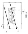
- FIG. 5illustrates an exemplary embodiment in which modeling software 20 displays virtual dental arch 82 within 3D environment 80 in a manner that allows practitioner 8 to view the cross section area 88 of virtual dental arch 82 while interacting with display area 60 to select the position of cross section planes 84 and 86 .
- practitioner 8has manipulated virtual dental arch 82 and oriented the virtual dental arch so that cross section planes 84 and 86 are substantially parallel to the computer screen, thereby exposing the defined cross section.
- the orientation of control image 62 within display area 60remains unchanged, allowing practitioner 8 to continue to manipulate parallel lines 66 and 68 to adjust cross section planes 84 and 86 .
- FIG. 6illustrates an exemplary embodiment similar to FIG. 5 , but in which parallel lines 66 and 68 are positioned to limit the overall width of control image 62 within display area 60 . Accordingly, display area 60 displays both not-in-view portions 64 of control image 62 as shaded portions. Additionally, virtual dental arch 82 is oriented within 3D environment 80 such that cross section planes 84 and 86 are not substantially parallel to the computer screen, but still allow practitioner 8 to view cross section area 88 of virtual dental arch 82 . In this manner, FIG. 6 illustrates the ability of modeling software 20 to allow practitioner 8 to view cross section area 88 of virtual dental arch 82 from various viewpoints by manipulating virtual dental arch within 3D environment 80 without altering the view of control image 62 .
- FIG. 7illustrates an exemplary embodiment in which practitioner 8 selects an occlusal (lateral) cross section.
- display area 60renders control image 62 as a front plan view image of a generic dental arch (or scaled version of the patient's dental arch) and the cross section controls comprise two horizontal lines 66 and 68 .
- the illustrated embodiment of FIG. 7may be particularly useful to determine which lateral edge of virtual dental arch initially penetrates cross section plane 84 .
- Practitioner 8may determine which lateral edge initially penetrates cross section plane 84 by moving horizontal line 66 up-and-down relative to control image 62 .
- practitioner 8may identify the initial lateral edge of virtual dental arch 82 to penetrate cross section plane 84 by moving horizontal line 66 towards the bottom of display area 60 from the illustrated position.
- the last cross section area 88 that is still visibleis the lateral edge.
- FIG. 8illustrates an exemplary embodiment in which practitioner 8 selects a frontal cross section.
- display area 60displays control image 62 as a side plan view image of a generic dental arch (or scaled image) and displays cross section controls as two vertical parallel lines 66 and 68 relationally linked with cross section planes 84 and 86 , respectively.
- FIG. 9illustrates another exemplary embodiment in which display area 60 allows practitioner 8 to rotate moveable parallel lines 66 and 68 to define angular cross sections through the patient's virtual dental arch.
Landscapes
- Health & Medical Sciences (AREA)
- Engineering & Computer Science (AREA)
- Computer Graphics (AREA)
- Computer Hardware Design (AREA)
- Life Sciences & Earth Sciences (AREA)
- Animal Behavior & Ethology (AREA)
- General Health & Medical Sciences (AREA)
- Public Health (AREA)
- Veterinary Medicine (AREA)
- Dentistry (AREA)
- Oral & Maxillofacial Surgery (AREA)
- Epidemiology (AREA)
- General Engineering & Computer Science (AREA)
- Software Systems (AREA)
- Physics & Mathematics (AREA)
- General Physics & Mathematics (AREA)
- Theoretical Computer Science (AREA)
- Dental Tools And Instruments Or Auxiliary Dental Instruments (AREA)
- Processing Or Creating Images (AREA)
- Apparatus For Radiation Diagnosis (AREA)
Abstract
Description
Claims (18)
Priority Applications (2)
| Application Number | Priority Date | Filing Date | Title |
|---|---|---|---|
| US11/275,236US7731495B2 (en) | 2005-12-20 | 2005-12-20 | User interface having cross section control tool for digital orthodontics |
| PCT/US2006/046960WO2007078610A2 (en) | 2005-12-20 | 2006-12-11 | User interface having cross section control tool for digital orthodontics |
Applications Claiming Priority (1)
| Application Number | Priority Date | Filing Date | Title |
|---|---|---|---|
| US11/275,236US7731495B2 (en) | 2005-12-20 | 2005-12-20 | User interface having cross section control tool for digital orthodontics |
Publications (2)
| Publication Number | Publication Date |
|---|---|
| US20070141526A1 US20070141526A1 (en) | 2007-06-21 |
| US7731495B2true US7731495B2 (en) | 2010-06-08 |
Family
ID=38174032
Family Applications (1)
| Application Number | Title | Priority Date | Filing Date |
|---|---|---|---|
| US11/275,236Expired - Fee RelatedUS7731495B2 (en) | 2005-12-20 | 2005-12-20 | User interface having cross section control tool for digital orthodontics |
Country Status (2)
| Country | Link |
|---|---|
| US (1) | US7731495B2 (en) |
| WO (1) | WO2007078610A2 (en) |
Cited By (23)
| Publication number | Priority date | Publication date | Assignee | Title |
|---|---|---|---|---|
| US8643569B2 (en) | 2010-07-14 | 2014-02-04 | Zspace, Inc. | Tools for use within a three dimensional scene |
| US20140115535A1 (en)* | 2012-10-18 | 2014-04-24 | Dental Imaging Technologies Corporation | Overlay maps for navigation of intraoral images |
| US9299183B2 (en) | 2010-07-02 | 2016-03-29 | Zspace, Inc. | Detection of partially obscured objects in three dimensional stereoscopic scenes |
| WO2019069166A1 (en) | 2017-10-06 | 2019-04-11 | 3M Innovative Properties Company | Removable dental appliance including spring member |
| WO2019069162A1 (en) | 2017-10-06 | 2019-04-11 | 3M Innovative Properties Company | Removable dental appliance including spring bellows |
| WO2019069164A1 (en) | 2017-10-06 | 2019-04-11 | 3M Innovative Properties Company | Removable dental appliance including jumpers |
| WO2019069165A1 (en) | 2017-10-06 | 2019-04-11 | 3M Innovative Properties Company | Removable dental appliance including positioning member |
| US10426574B2 (en) | 2014-12-30 | 2019-10-01 | 3M Innovative Properties Company | Computer system-aided design of dental appliances |
| WO2020065538A1 (en) | 2018-09-26 | 2020-04-02 | 3M Innovative Properties Company | Parylene dental articles |
| US10722331B2 (en) | 2014-12-09 | 2020-07-28 | 3M Innovative Properties Company | Dental restoration molding techniques |
| US11058516B2 (en) | 2017-10-06 | 2021-07-13 | 3M Innovative Properties Company | Orthodontic palatal expander including split beams |
| US11123165B2 (en) | 2015-12-17 | 2021-09-21 | 3M Innovative Properties Company | Dental restoration molds |
| US11185392B2 (en) | 2015-12-17 | 2021-11-30 | 3M Innovative Properties Company | One-piece dental restoration molds |
| US11351012B2 (en) | 2016-12-16 | 2022-06-07 | 3M Innovative Properties Company | Orthodontic bracket footing |
| US11547530B2 (en) | 2016-07-26 | 2023-01-10 | 3M Innovative Properties Company | Dental restoration molds |
| US11737855B2 (en) | 2018-11-15 | 2023-08-29 | 3M Innovative Properties Company | Removable dental appliance with interproximal reinforcement |
| US11737856B2 (en) | 2018-11-15 | 2023-08-29 | 3M Innovative Properties Company | Removable dental appliance with gingival ridges |
| US11737854B2 (en) | 2017-03-15 | 2023-08-29 | 3M Innovative Properties Company | Removable orthodontic appliance system |
| US11801126B2 (en) | 2017-09-19 | 2023-10-31 | 3M Innovative Properties Company | Dental restoration molds |
| US12076210B2 (en) | 2016-12-09 | 2024-09-03 | Solventum Intellectual Properties Company | Elastomeric orthodontic bracket |
| US12156775B2 (en) | 2016-07-26 | 2024-12-03 | Solventum Intellectual Properties Company | Dental restoration molds |
| US12186144B2 (en) | 2018-08-10 | 2025-01-07 | Solventum Intellectual Properties Company | Dental restoration molds |
| US12201490B2 (en) | 2021-08-30 | 2025-01-21 | Solventum Intellectual Properties Compay | Digital design of dental matrix with improved customized interproximal contacts |
Families Citing this family (71)
| Publication number | Priority date | Publication date | Assignee | Title |
|---|---|---|---|---|
| US11026768B2 (en) | 1998-10-08 | 2021-06-08 | Align Technology, Inc. | Dental appliance reinforcement |
| US7904308B2 (en) | 2006-04-18 | 2011-03-08 | Align Technology, Inc. | Method and system for providing indexing and cataloguing of orthodontic related treatment profiles and options |
| US9492245B2 (en) | 2004-02-27 | 2016-11-15 | Align Technology, Inc. | Method and system for providing dynamic orthodontic assessment and treatment profiles |
| US7880751B2 (en)* | 2004-02-27 | 2011-02-01 | Align Technology, Inc. | Method and system for providing dynamic orthodontic assessment and treatment profiles |
| US7653455B2 (en)* | 2006-07-28 | 2010-01-26 | 3M Innovative Properties Company | Computer-aided implanting of orthodontic anchorage devices using surgical guides |
| US7878805B2 (en) | 2007-05-25 | 2011-02-01 | Align Technology, Inc. | Tabbed dental appliance |
| US8738394B2 (en) | 2007-11-08 | 2014-05-27 | Eric E. Kuo | Clinical data file |
| US8108189B2 (en) | 2008-03-25 | 2012-01-31 | Align Technologies, Inc. | Reconstruction of non-visible part of tooth |
| US9492243B2 (en) | 2008-05-23 | 2016-11-15 | Align Technology, Inc. | Dental implant positioning |
| US8092215B2 (en) | 2008-05-23 | 2012-01-10 | Align Technology, Inc. | Smile designer |
| US8172569B2 (en) | 2008-06-12 | 2012-05-08 | Align Technology, Inc. | Dental appliance |
| US9503282B2 (en) | 2008-09-19 | 2016-11-22 | 3M Innovative Properties Company | Methods and systems for determining the positions of orthodontic appliances |
| US8152518B2 (en) | 2008-10-08 | 2012-04-10 | Align Technology, Inc. | Dental positioning appliance having metallic portion |
| US8292617B2 (en) | 2009-03-19 | 2012-10-23 | Align Technology, Inc. | Dental wire attachment |
| US8765031B2 (en) | 2009-08-13 | 2014-07-01 | Align Technology, Inc. | Method of forming a dental appliance |
| JP5323194B2 (en)* | 2009-08-21 | 2013-10-23 | 株式会社東芝 | Medical image processing apparatus and method |
| US9211166B2 (en) | 2010-04-30 | 2015-12-15 | Align Technology, Inc. | Individualized orthodontic treatment index |
| US9241774B2 (en) | 2010-04-30 | 2016-01-26 | Align Technology, Inc. | Patterned dental positioning appliance |
| US8594820B2 (en) | 2010-09-17 | 2013-11-26 | Nobel Biocare Services Ag | Prosthesis manipulation in dental prosthesis design |
| US9403238B2 (en) | 2011-09-21 | 2016-08-02 | Align Technology, Inc. | Laser cutting |
| US9881419B1 (en)* | 2012-02-02 | 2018-01-30 | Bentley Systems, Incorporated | Technique for providing an initial pose for a 3-D model |
| US9375300B2 (en) | 2012-02-02 | 2016-06-28 | Align Technology, Inc. | Identifying forces on a tooth |
| US9220580B2 (en) | 2012-03-01 | 2015-12-29 | Align Technology, Inc. | Determining a dental treatment difficulty |
| US9414897B2 (en) | 2012-05-22 | 2016-08-16 | Align Technology, Inc. | Adjustment of tooth position in a virtual dental model |
| US9123147B2 (en)* | 2012-09-07 | 2015-09-01 | Carestream Health, Inc. | Imaging apparatus for display of maxillary and mandibular arches |
| EP3060972A4 (en)* | 2013-10-22 | 2017-10-18 | Nokia Technologies Oy | Apparatus and method for providing for receipt of indirect touch input to a touch screen display |
| US9610141B2 (en) | 2014-09-19 | 2017-04-04 | Align Technology, Inc. | Arch expanding appliance |
| US10449016B2 (en) | 2014-09-19 | 2019-10-22 | Align Technology, Inc. | Arch adjustment appliance |
| JP6047136B2 (en)* | 2014-11-11 | 2016-12-21 | 株式会社日本製鋼所 | Simulation device, simulation method thereof, and simulation program |
| US9744001B2 (en) | 2014-11-13 | 2017-08-29 | Align Technology, Inc. | Dental appliance with cavity for an unerupted or erupting tooth |
| US10504386B2 (en) | 2015-01-27 | 2019-12-10 | Align Technology, Inc. | Training method and system for oral-cavity-imaging-and-modeling equipment |
| US11931222B2 (en) | 2015-11-12 | 2024-03-19 | Align Technology, Inc. | Dental attachment formation structures |
| US11554000B2 (en) | 2015-11-12 | 2023-01-17 | Align Technology, Inc. | Dental attachment formation structure |
| US11596502B2 (en) | 2015-12-09 | 2023-03-07 | Align Technology, Inc. | Dental attachment placement structure |
| US11103330B2 (en) | 2015-12-09 | 2021-08-31 | Align Technology, Inc. | Dental attachment placement structure |
| JP6804217B2 (en)* | 2016-05-18 | 2020-12-23 | キヤノンメディカルシステムズ株式会社 | Medical image processing device |
| WO2017218947A1 (en) | 2016-06-17 | 2017-12-21 | Align Technology, Inc. | Intraoral appliances with sensing |
| US10383705B2 (en) | 2016-06-17 | 2019-08-20 | Align Technology, Inc. | Orthodontic appliance performance monitor |
| US10331859B2 (en)* | 2016-06-21 | 2019-06-25 | Clearcorrect Operating, Llc | Orthodontic treatment simulation having improved graphics processing for virtual modeling |
| CA3030676A1 (en) | 2016-07-27 | 2018-02-01 | Align Technology, Inc. | Intraoral scanner with dental diagnostics capabilities |
| CN117257492A (en) | 2016-11-04 | 2023-12-22 | 阿莱恩技术有限公司 | Method and apparatus for dental imaging |
| AU2017366755B2 (en) | 2016-12-02 | 2022-07-28 | Align Technology, Inc. | Methods and apparatuses for customizing rapid palatal expanders using digital models |
| US11026831B2 (en) | 2016-12-02 | 2021-06-08 | Align Technology, Inc. | Dental appliance features for speech enhancement |
| WO2018102770A1 (en) | 2016-12-02 | 2018-06-07 | Align Technology, Inc. | Force control, stop mechanism, regulating structure of removable arch adjustment appliance |
| EP3547952B1 (en) | 2016-12-02 | 2020-11-04 | Align Technology, Inc. | Palatal expander |
| US10548700B2 (en) | 2016-12-16 | 2020-02-04 | Align Technology, Inc. | Dental appliance etch template |
| US10779718B2 (en) | 2017-02-13 | 2020-09-22 | Align Technology, Inc. | Cheek retractor and mobile device holder |
| WO2018183358A1 (en) | 2017-03-27 | 2018-10-04 | Align Technology, Inc. | Apparatuses and methods assisting in dental therapies |
| US10613515B2 (en) | 2017-03-31 | 2020-04-07 | Align Technology, Inc. | Orthodontic appliances including at least partially un-erupted teeth and method of forming them |
| US11045283B2 (en) | 2017-06-09 | 2021-06-29 | Align Technology, Inc. | Palatal expander with skeletal anchorage devices |
| CN116942335A (en) | 2017-06-16 | 2023-10-27 | 阿莱恩技术有限公司 | Automatic detection of tooth type and eruption status |
| US10639134B2 (en) | 2017-06-26 | 2020-05-05 | Align Technology, Inc. | Biosensor performance indicator for intraoral appliances |
| US10885521B2 (en) | 2017-07-17 | 2021-01-05 | Align Technology, Inc. | Method and apparatuses for interactive ordering of dental aligners |
| CN111107806B (en) | 2017-07-21 | 2022-04-19 | 阿莱恩技术有限公司 | Jaw profile anchoring |
| CN110996842B (en) | 2017-07-27 | 2022-10-14 | 阿莱恩技术有限公司 | Tooth Staining, Transparency and Glazing |
| EP4278957A3 (en) | 2017-07-27 | 2024-01-24 | Align Technology, Inc. | System and methods for processing an orthodontic aligner by means of an optical coherence tomography |
| US12274597B2 (en) | 2017-08-11 | 2025-04-15 | Align Technology, Inc. | Dental attachment template tray systems |
| US11116605B2 (en) | 2017-08-15 | 2021-09-14 | Align Technology, Inc. | Buccal corridor assessment and computation |
| US11123156B2 (en) | 2017-08-17 | 2021-09-21 | Align Technology, Inc. | Dental appliance compliance monitoring |
| US12171575B2 (en) | 2017-10-04 | 2024-12-24 | Align Technology, Inc. | Intraoral systems and methods for sampling soft-tissue |
| US10813720B2 (en) | 2017-10-05 | 2020-10-27 | Align Technology, Inc. | Interproximal reduction templates |
| CN111565668B (en) | 2017-10-27 | 2022-06-07 | 阿莱恩技术有限公司 | Substitute occlusion adjusting structure |
| CN111295153B (en) | 2017-10-31 | 2023-06-16 | 阿莱恩技术有限公司 | Dental appliance with selective bite loading and controlled tip staggering |
| CN119235481A (en) | 2017-11-01 | 2025-01-03 | 阿莱恩技术有限公司 | Automatic treatment planning |
| US11534974B2 (en) | 2017-11-17 | 2022-12-27 | Align Technology, Inc. | Customized fabrication of orthodontic retainers based on patient anatomy |
| US11219506B2 (en) | 2017-11-30 | 2022-01-11 | Align Technology, Inc. | Sensors for monitoring oral appliances |
| US11432908B2 (en) | 2017-12-15 | 2022-09-06 | Align Technology, Inc. | Closed loop adaptive orthodontic treatment methods and apparatuses |
| US10980613B2 (en) | 2017-12-29 | 2021-04-20 | Align Technology, Inc. | Augmented reality enhancements for dental practitioners |
| US10813727B2 (en) | 2018-01-26 | 2020-10-27 | Align Technology, Inc. | Diagnostic intraoral tracking |
| US11937991B2 (en) | 2018-03-27 | 2024-03-26 | Align Technology, Inc. | Dental attachment placement structure |
| EP3773320B1 (en) | 2018-04-11 | 2024-05-15 | Align Technology, Inc. | Releasable palatal expanders |
Citations (18)
| Publication number | Priority date | Publication date | Assignee | Title |
|---|---|---|---|---|
| US5623583A (en)* | 1994-03-16 | 1997-04-22 | Fujitsu Limited | Three-dimensional model cross-section instruction system |
| WO1998053428A1 (en) | 1997-05-20 | 1998-11-26 | Cadent Ltd. | Computer user interface for orthodontic use |
| US20020010568A1 (en)* | 1999-11-30 | 2002-01-24 | Rudger Rubbert | Orthodontic treatment planning with user-specified simulation of tooth movement |
| US20020015006A1 (en)* | 2000-04-28 | 2002-02-07 | Masakazu Suzuki | Display method and apparatus for displaying three-dimensional data as a combination of three sectional images, recording medium in which a computer readable program is saved for executing the method, and computer readable program for executing the method |
| US20020025503A1 (en)* | 1999-12-29 | 2002-02-28 | Eric Chapoulaud | Custom orthodontic appliance forming method and apparatus |
| US20030215764A1 (en)* | 2002-05-02 | 2003-11-20 | Avi Kopelman | Method and system for assessing the outcome of an orthodontic treatment |
| US20040096799A1 (en)* | 2000-03-30 | 2004-05-20 | Align Technology, Inc. | System and method for separating three-dimensional models |
| US20040175670A1 (en) | 2002-01-29 | 2004-09-09 | Cadent Ltd. | Method and system for assisting in applying an orthodontic treatment |
| US20040197727A1 (en) | 2001-04-13 | 2004-10-07 | Orametrix, Inc. | Method and system for comprehensive evaluation of orthodontic treatment using unified workstation |
| US20050033160A1 (en)* | 2003-06-27 | 2005-02-10 | Kabushiki Kaisha Toshiba | Image processing/displaying apparatus and method of controlling the same |
| US6898302B1 (en) | 1999-05-21 | 2005-05-24 | Emory University | Systems, methods and computer program products for the display and visually driven definition of tomographic image planes in three-dimensional space |
| US20050130095A1 (en) | 2003-12-12 | 2005-06-16 | 3M Innovative Properties Company | Method of orienting an orthodontic appliance to a tooth |
| US20050170309A1 (en) | 2004-02-04 | 2005-08-04 | 3M Innovative Properties Company | Planar guides to visually aid orthodontic appliance placement within a three-dimensional (3D) environment |
| US20050214707A1 (en) | 2004-03-25 | 2005-09-29 | Kambiz Kohani | Dental bracketing system and method |
| US6976840B2 (en) | 1997-09-30 | 2005-12-20 | Cadent Ltd. | Placing an orthodontic element on a tooth surface |
| US20060024637A1 (en) | 2004-07-30 | 2006-02-02 | 3M Innovative Properties Company | Automatic adjustment of an orthodontic bracket to a desired occlusal height within a three-dimensional (3D) environment |
| US20060073436A1 (en) | 2004-10-06 | 2006-04-06 | 3M Innovative Properties Company | Movement of orthodontic objects along a virtual archwire within a three-dimensional (3D) environment |
| US7033327B2 (en) | 2002-09-13 | 2006-04-25 | 3M Innovative Properties Company | Method of determining the long axis of an object |
- 2005
- 2005-12-20USUS11/275,236patent/US7731495B2/ennot_activeExpired - Fee Related
- 2006
- 2006-12-11WOPCT/US2006/046960patent/WO2007078610A2/enactiveApplication Filing
Patent Citations (19)
| Publication number | Priority date | Publication date | Assignee | Title |
|---|---|---|---|---|
| US5623583A (en)* | 1994-03-16 | 1997-04-22 | Fujitsu Limited | Three-dimensional model cross-section instruction system |
| WO1998053428A1 (en) | 1997-05-20 | 1998-11-26 | Cadent Ltd. | Computer user interface for orthodontic use |
| US6664986B1 (en) | 1997-05-20 | 2003-12-16 | Cadent Ltd. | Computer user interface for orthodontic use |
| US6976840B2 (en) | 1997-09-30 | 2005-12-20 | Cadent Ltd. | Placing an orthodontic element on a tooth surface |
| US6898302B1 (en) | 1999-05-21 | 2005-05-24 | Emory University | Systems, methods and computer program products for the display and visually driven definition of tomographic image planes in three-dimensional space |
| US20020010568A1 (en)* | 1999-11-30 | 2002-01-24 | Rudger Rubbert | Orthodontic treatment planning with user-specified simulation of tooth movement |
| US20020025503A1 (en)* | 1999-12-29 | 2002-02-28 | Eric Chapoulaud | Custom orthodontic appliance forming method and apparatus |
| US20040096799A1 (en)* | 2000-03-30 | 2004-05-20 | Align Technology, Inc. | System and method for separating three-dimensional models |
| US20020015006A1 (en)* | 2000-04-28 | 2002-02-07 | Masakazu Suzuki | Display method and apparatus for displaying three-dimensional data as a combination of three sectional images, recording medium in which a computer readable program is saved for executing the method, and computer readable program for executing the method |
| US20040197727A1 (en) | 2001-04-13 | 2004-10-07 | Orametrix, Inc. | Method and system for comprehensive evaluation of orthodontic treatment using unified workstation |
| US20040175670A1 (en) | 2002-01-29 | 2004-09-09 | Cadent Ltd. | Method and system for assisting in applying an orthodontic treatment |
| US20030215764A1 (en)* | 2002-05-02 | 2003-11-20 | Avi Kopelman | Method and system for assessing the outcome of an orthodontic treatment |
| US7033327B2 (en) | 2002-09-13 | 2006-04-25 | 3M Innovative Properties Company | Method of determining the long axis of an object |
| US20050033160A1 (en)* | 2003-06-27 | 2005-02-10 | Kabushiki Kaisha Toshiba | Image processing/displaying apparatus and method of controlling the same |
| US20050130095A1 (en) | 2003-12-12 | 2005-06-16 | 3M Innovative Properties Company | Method of orienting an orthodontic appliance to a tooth |
| US20050170309A1 (en) | 2004-02-04 | 2005-08-04 | 3M Innovative Properties Company | Planar guides to visually aid orthodontic appliance placement within a three-dimensional (3D) environment |
| US20050214707A1 (en) | 2004-03-25 | 2005-09-29 | Kambiz Kohani | Dental bracketing system and method |
| US20060024637A1 (en) | 2004-07-30 | 2006-02-02 | 3M Innovative Properties Company | Automatic adjustment of an orthodontic bracket to a desired occlusal height within a three-dimensional (3D) environment |
| US20060073436A1 (en) | 2004-10-06 | 2006-04-06 | 3M Innovative Properties Company | Movement of orthodontic objects along a virtual archwire within a three-dimensional (3D) environment |
Non-Patent Citations (3)
| Title |
|---|
| Anatomy Browser: A novel approach to visualization and integration of medical information; Goliand et al., Computer Assisted Surgery, 4:129-143, 1999. |
| User Controlled Overviews of an Image Library: A Case Study of the Visible Human; North et al., Human-Computer Interaction Laboratory, Department of Computer Science, Institute for Systems Research, University of Maryland, 1996, pp. 74-82. |
| Visualization in biomedical computing, Richard A. Robb, Parallel Computing 25 (1999) 2067-2110. |
Cited By (43)
| Publication number | Priority date | Publication date | Assignee | Title |
|---|---|---|---|---|
| US9299183B2 (en) | 2010-07-02 | 2016-03-29 | Zspace, Inc. | Detection of partially obscured objects in three dimensional stereoscopic scenes |
| US9704285B2 (en) | 2010-07-02 | 2017-07-11 | Zspace, Inc. | Detection of partially obscured objects in three dimensional stereoscopic scenes |
| US8643569B2 (en) | 2010-07-14 | 2014-02-04 | Zspace, Inc. | Tools for use within a three dimensional scene |
| US20140115535A1 (en)* | 2012-10-18 | 2014-04-24 | Dental Imaging Technologies Corporation | Overlay maps for navigation of intraoral images |
| US9361003B2 (en)* | 2012-10-18 | 2016-06-07 | Dental Imaging Technologies Corporation | Overlay maps for navigation of intraoral images |
| US9703455B2 (en) | 2012-10-18 | 2017-07-11 | Dental Imaging Technologies Corporation | Overlay maps for navigation of intraoral images |
| US11571284B2 (en) | 2014-12-09 | 2023-02-07 | 3M Innovative Properties Company | Dental restoration molding techniques |
| US10722331B2 (en) | 2014-12-09 | 2020-07-28 | 3M Innovative Properties Company | Dental restoration molding techniques |
| US10426574B2 (en) | 2014-12-30 | 2019-10-01 | 3M Innovative Properties Company | Computer system-aided design of dental appliances |
| US11103328B2 (en) | 2014-12-30 | 2021-08-31 | 3M Innovative Properties Company | Dental appliance providing exposed occlusal surfaces |
| US11925522B2 (en) | 2015-12-17 | 2024-03-12 | 3M Innovative Properties Company | Dental restoration molds |
| US12127904B2 (en) | 2015-12-17 | 2024-10-29 | Solventum Intellectual Properties Company | One-piece dental restoration molds |
| US11123165B2 (en) | 2015-12-17 | 2021-09-21 | 3M Innovative Properties Company | Dental restoration molds |
| US11185392B2 (en) | 2015-12-17 | 2021-11-30 | 3M Innovative Properties Company | One-piece dental restoration molds |
| EP3967261A1 (en) | 2015-12-17 | 2022-03-16 | 3M Innovative Properties Company | Dental restoration molds |
| US12324715B2 (en) | 2015-12-17 | 2025-06-10 | Solventum Intellectual Properties Company | Dental restoration molds |
| US11547530B2 (en) | 2016-07-26 | 2023-01-10 | 3M Innovative Properties Company | Dental restoration molds |
| US12156775B2 (en) | 2016-07-26 | 2024-12-03 | Solventum Intellectual Properties Company | Dental restoration molds |
| US12076210B2 (en) | 2016-12-09 | 2024-09-03 | Solventum Intellectual Properties Company | Elastomeric orthodontic bracket |
| US11351012B2 (en) | 2016-12-16 | 2022-06-07 | 3M Innovative Properties Company | Orthodontic bracket footing |
| US11737854B2 (en) | 2017-03-15 | 2023-08-29 | 3M Innovative Properties Company | Removable orthodontic appliance system |
| US11801126B2 (en) | 2017-09-19 | 2023-10-31 | 3M Innovative Properties Company | Dental restoration molds |
| US11173015B2 (en) | 2017-10-06 | 2021-11-16 | 3M Innovative Properties Company | Removable dental appliance including spring member |
| US11517401B2 (en) | 2017-10-06 | 2022-12-06 | 3M Innovative Properties Company | Removable dental appliance including spring bellows |
| US11395718B2 (en) | 2017-10-06 | 2022-07-26 | 3M Innovative Properties Company | Removable dental appliance including jumpers |
| WO2019069162A1 (en) | 2017-10-06 | 2019-04-11 | 3M Innovative Properties Company | Removable dental appliance including spring bellows |
| EP4585184A2 (en) | 2017-10-06 | 2025-07-16 | Solventum Intellectual Properties Company | Removable dental appliance including spring member and computer method of designing said appliance |
| EP4585185A2 (en) | 2017-10-06 | 2025-07-16 | Solventum Intellectual Properties Company | Removable dental appliance including spring member and computer method of designing said appliance |
| US11446117B2 (en) | 2017-10-06 | 2022-09-20 | 3M Innovative Properties Company | Removable dental appliance including positioning member |
| WO2019069164A1 (en) | 2017-10-06 | 2019-04-11 | 3M Innovative Properties Company | Removable dental appliance including jumpers |
| WO2019069166A1 (en) | 2017-10-06 | 2019-04-11 | 3M Innovative Properties Company | Removable dental appliance including spring member |
| US12023219B2 (en) | 2017-10-06 | 2024-07-02 | Solventum Intellectual Properties Company | Removable dental appliance including spring member |
| US11058516B2 (en) | 2017-10-06 | 2021-07-13 | 3M Innovative Properties Company | Orthodontic palatal expander including split beams |
| WO2019069165A1 (en) | 2017-10-06 | 2019-04-11 | 3M Innovative Properties Company | Removable dental appliance including positioning member |
| US12186144B2 (en) | 2018-08-10 | 2025-01-07 | Solventum Intellectual Properties Company | Dental restoration molds |
| US11291526B2 (en) | 2018-09-26 | 2022-04-05 | 3M Innovative Properties Company | Parylene dental articles |
| WO2020065538A1 (en) | 2018-09-26 | 2020-04-02 | 3M Innovative Properties Company | Parylene dental articles |
| EP4393707A2 (en) | 2018-11-15 | 2024-07-03 | Solventum Intellectual Properties Company | Removable dental appliance with interproximal reinforcement |
| EP4506167A2 (en) | 2018-11-15 | 2025-02-12 | Solventum Intellectual Properties Company | Removable dental appliance with gingival ridges |
| US12239507B2 (en) | 2018-11-15 | 2025-03-04 | Solventum Intellectual Properties Company | Removable dental appliance with gingival ridges |
| US11737856B2 (en) | 2018-11-15 | 2023-08-29 | 3M Innovative Properties Company | Removable dental appliance with gingival ridges |
| US11737855B2 (en) | 2018-11-15 | 2023-08-29 | 3M Innovative Properties Company | Removable dental appliance with interproximal reinforcement |
| US12201490B2 (en) | 2021-08-30 | 2025-01-21 | Solventum Intellectual Properties Compay | Digital design of dental matrix with improved customized interproximal contacts |
Also Published As
| Publication number | Publication date |
|---|---|
| WO2007078610A3 (en) | 2008-03-20 |
| WO2007078610A2 (en) | 2007-07-12 |
| US20070141526A1 (en) | 2007-06-21 |
Similar Documents
| Publication | Publication Date | Title |
|---|---|---|
| US7731495B2 (en) | User interface having cross section control tool for digital orthodontics | |
| US11925525B2 (en) | Three-dimensional visualization of clinical dentition incorporating view state and modified clinical data | |
| US12245883B2 (en) | Dental panoramic views | |
| US20210378791A1 (en) | Generating a dynamic three-dimensional occlusogram | |
| US8805048B2 (en) | Method and system for orthodontic diagnosis | |
| EP2706509B1 (en) | Imaging apparatus for display of maxillary and mandibular arches | |
| US8517727B2 (en) | Automatic adjustment of an orthodontic bracket to a desired occlusal height within a three-dimensional (3D) environment | |
| EP1711120B1 (en) | Planar guides to visually aid orthodontic appliance placement within a three-dimensional (3d) environment | |
| US10667887B2 (en) | Video-assisted margin marking for dental models | |
| JP5209631B2 (en) | Digital orthodontic treatment plan | |
| EP3527163B1 (en) | Computer implemented method for modifying a digital three-dimensional model of a dentition | |
| US9730776B2 (en) | Display method and system for enabling an operator to visualize and correct alignment errors in imaged data sets | |
| EP4095808A1 (en) | Method and system for interactively rendering digital dental models | |
| Li et al. | Orthodontic simulation and diagnosis: an enhanced tool for dentists | |
| KR20250060073A (en) | Method for providing orthodontic image and apparatus thereof |
Legal Events
| Date | Code | Title | Description |
|---|---|---|---|
| AS | Assignment | Owner name:3M INNOVATIVE PROPERTIES COMPANY, MINNESOTA Free format text:ASSIGNMENT OF ASSIGNORS INTEREST;ASSIGNORS:EISENBERG, PETER M.;STARK, NICHOLAS A.;RABY, RICHARD E.;REEL/FRAME:016924/0563 Effective date:20051220 Owner name:3M INNOVATIVE PROPERTIES COMPANY,MINNESOTA Free format text:ASSIGNMENT OF ASSIGNORS INTEREST;ASSIGNORS:EISENBERG, PETER M.;STARK, NICHOLAS A.;RABY, RICHARD E.;REEL/FRAME:016924/0563 Effective date:20051220 | |
| STCF | Information on status: patent grant | Free format text:PATENTED CASE | |
| FPAY | Fee payment | Year of fee payment:4 | |
| MAFP | Maintenance fee payment | Free format text:PAYMENT OF MAINTENANCE FEE, 8TH YEAR, LARGE ENTITY (ORIGINAL EVENT CODE: M1552) Year of fee payment:8 | |
| FEPP | Fee payment procedure | Free format text:MAINTENANCE FEE REMINDER MAILED (ORIGINAL EVENT CODE: REM.); ENTITY STATUS OF PATENT OWNER: LARGE ENTITY | |
| LAPS | Lapse for failure to pay maintenance fees | Free format text:PATENT EXPIRED FOR FAILURE TO PAY MAINTENANCE FEES (ORIGINAL EVENT CODE: EXP.); ENTITY STATUS OF PATENT OWNER: LARGE ENTITY | |
| STCH | Information on status: patent discontinuation | Free format text:PATENT EXPIRED DUE TO NONPAYMENT OF MAINTENANCE FEES UNDER 37 CFR 1.362 | |
| FP | Lapsed due to failure to pay maintenance fee | Effective date:20220608 |