US7731231B2 - Airbag vent tube - Google Patents
Airbag vent tubeDownload PDFInfo
- Publication number
- US7731231B2 US7731231B2US11/786,559US78655907AUS7731231B2US 7731231 B2US7731231 B2US 7731231B2US 78655907 AUS78655907 AUS 78655907AUS 7731231 B2US7731231 B2US 7731231B2
- Authority
- US
- United States
- Prior art keywords
- vent tube
- airbag cushion
- housing opening
- airbag
- inflatable airbag
- Prior art date
- Legal status (The legal status is an assumption and is not a legal conclusion. Google has not performed a legal analysis and makes no representation as to the accuracy of the status listed.)
- Expired - Fee Related, expires
Links
- 239000007789gasSubstances0.000description16
- 238000013022ventingMethods0.000description9
- 208000027418Wounds and injuryDiseases0.000description1
- 239000000853adhesiveSubstances0.000description1
- 230000001070adhesive effectEffects0.000description1
- 239000002537cosmeticSubstances0.000description1
- 230000006378damageEffects0.000description1
- 239000004744fabricSubstances0.000description1
- 230000003116impacting effectEffects0.000description1
- 208000014674injuryDiseases0.000description1
- 210000003127kneeAnatomy0.000description1
- 238000000034methodMethods0.000description1
- 238000012986modificationMethods0.000description1
- 230000004048modificationEffects0.000description1
- 230000001681protective effectEffects0.000description1
- 238000009958sewingMethods0.000description1
Images


Classifications
- B—PERFORMING OPERATIONS; TRANSPORTING
- B60—VEHICLES IN GENERAL
- B60R—VEHICLES, VEHICLE FITTINGS, OR VEHICLE PARTS, NOT OTHERWISE PROVIDED FOR
- B60R21/00—Arrangements or fittings on vehicles for protecting or preventing injuries to occupants or pedestrians in case of accidents or other traffic risks
- B60R21/02—Occupant safety arrangements or fittings, e.g. crash pads
- B60R21/16—Inflatable occupant restraints or confinements designed to inflate upon impact or impending impact, e.g. air bags
- B60R21/23—Inflatable members
- B60R21/239—Inflatable members characterised by their venting means
Definitions
- the present inventionrelates generally to the field of automotive protective systems. More specifically, the present invention relates to inflatable airbags for automobiles.
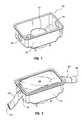
- FIG. 1is a schematic view of an airbag module.
- FIG. 2is a schematic view of an airbag module.
- FIG. 3is a side view of an airbag module.
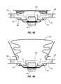
- FIG. 4Ais a cross-sectional view of an airbag module.
- FIG. 4Bis a cross-sectional view of a partially deployed airbag module.
- FIG. 4Cis a cross-sectional view of a fully deployed airbag module.
- FIG. 4Dis a cross-sectional view of a fully deployed airbag module with tethered vent tubes.
- FIGS. 5A-5Cshow the deployment of an airbag module with a normally positioned occupant.
- FIGS. 6A-6Cshow the deployment of an airbag module with an out-of-position occupant.
- a motor vehicle airbag module and airbag cushion vent tubeDescribed below are embodiments of a motor vehicle airbag module and airbag cushion vent tube.
- the principles of the inventionmay be applied to and used with a variety of airbag deployment systems including frontal driver and passenger airbags, knee airbags, overhead airbags, curtain airbags, and the like.
- the present inventionis applicable to vehicle airbag cushions of various shapes and sizes.
- Airbag cushionsare frequently located in an instrument panel and directly in front of an occupant. During a collision, an airbag cushion inflates and deploys through a cosmetic cover. The airbag cushion deploys towards the occupant and provides a restraint.
- Full inflation of an airbagis not always desired when there is an obstruction in the path of deployment such as when an occupant is near or out of position relative to the airbag cover.
- An out-of-position occupantmay experience punch-out forces when the airbag initially breaks through the cover and deploys into the near or out-of-position occupant.
- a partial airbag inflationmay offer optimal protection.
- partial airbag inflationmay be desired when the occupant being protected by the airbag cushion is a child, a baby in a rear facing car seat or an adult positioned too close to the air bag cushion.
- Embodiments described belowinclude vehicle airbag systems that respond to an occupant's position and control the airbag cushion inflation to avoid excessive punch-out and deployment forces.
- FIG. 1is a perspective view which shows an airbag module 100 which can include a module housing 110 and an inflator 115 configured to deliver gas into an airbag cushion such as the airbag cushion 200 shown in FIG. 2 .
- the airbag cushion 200may include at least one vent tube, such as vent tubes 230 . Gas may enter the interior of the airbag cushion 200 through the inflator 115 and completely inflate the airbag cushion 200 during deployment. The gas may also exit the interior of the airbag cushion 200 through vent tubes 230 during deployment and if complete inflation of the airbag cushion 200 is not desired.
- vent tubes 230may be located where desired on the airbag cushion 200 .
- the diameter of the vent tubes 230can be adjusted by controlling the area of the opening at the vent tube exit 234 .
- the area of the opening at the vent tube exit 234may be sewn or bonded to adjust the size of the opening.
- the location of a vent tube on the airbag cushion 200may depend on the airbag module deployment angle, vehicle interior geometry, and cushion fold type.
- vent tubes 230may be located on the side, top, bottom, or rear of the airbag cushion 200 .
- the size and length of the vent tubes 230may be modified as desired and adjusted to control and optimize venting and closing during airbag deployment.
- the vent tubes 230may be attached to the airbag cushion 200 by any appropriate method such as by sewing, stapling, or using an adhesive.
- the vent tubes 230may also be integral to the airbag cushion 200 .
- the airbag module 100may include a module housing 110 configured with one or more housing openings such as housing openings 130 configured to be aligned with the vent tubes 230 and allow the vent tubes 230 to vent inflation gas through the housing openings 130 during airbag deployment.
- the alignment of the vent tubes 230 with the housing openings 130may be controlled by cinching the vent tubes 230 after the airbag cushion 200 has been folded (not shown).
- the vent tubes 230may extend through the housing openings 130 and beyond the module housing 110 before deployment and during deployment.
- the airbag module 100may also include a diffuser such as diffuser 120 configured to direct the inflation gas toward the vent tubes 230 during airbag inflation. More particularly, a loop diffuser may be sewn inside the airbag cushion 200 .
- the module housing 110can include a housing diffuser.
- the diffuser 120may be attached to the airbag cushion 200 or disposed on the module housing 110 .
- the diffusermay be rectangular, trapezoidal, hexagonal, round, etc. It may also have a portion which is round or elliptical while other portions are angled.
- diffuser 120functions to direct at least a portion of the inflation gas generally toward the vent tube(s).
- the airbag cushion side panelscan expand and move during inflation such that the inflation gas flow becomes misaligned with the vent tubes 230 .
- the vent tubes 230may be closed as the airbag cushion fully expands thus, retaining gas for normal occupant restraint.
- FIGS. 4A-4Cprovide a cross-sectional view of an airbag cushion 300 deploying from a module housing 310 .
- multiple vent tubes 330are shown in FIGS. 4A-4C , however one or more vent tubes may be used to vent the inflation gas from the airbag cushion 300 .
- the initially deploying airbag cushion 300may include vent tubes 330 symmetrically attached and extending out of the module housing 310 at housing openings 313 .
- the airbag cushion 300may be folded within the module housing 310 and may include areas of slack both above and below the vent tubes 330 as shown by FIG. 4A .
- the inflation gassesrepresented by the arrows, are generated by the inflator 315 and may flow out of the diffuser 320 and into the airbag cushion 300 and out of the vent tubes 330 .
- the airbag cushion 300may fully inflate as illustrated by FIG. 4C .
- the folds in the fabric both above and below the vent tubes 330may have been removed and the tension of the inflating airbag cushion 300 may place the vent tubes 330 out of alignment with the housing openings 313 .
- the vent tubes 330may be pulled through the housing openings 313 at an angle thereby obstructing the exit of the inflation gases out of the at least partially closed vent tubes 330 .
- the obstruction of the vent tubes 330may allow the inflation gasses to fully inflate the airbag cushion 300 and provide the optimal protection for a properly positioned occupant.
- the vent tubes 330may be tethered to the airbag cushion 300 such that as the airbag cushion 300 nears full inflation the tension of the inflating airbag will tighten the tethers and cause the vent tubes 330 to be withdrawn from the housing openings 313 and pulled closed.
- tethers 335may be attached to the vent tubes 330 and to the internal surface of the airbag cushion 300 . When the airbag cushion 300 is in the undeployed or partially deployed state, the tethers 335 would be slack within the airbag leaving the vent tubes 330 open for the exit of inflation gasses.
- the expansion of the pressure of the inflation gasses against the internal surface of the airbag cushion 300may tighten the tethers 335 and cause the vent tubes 330 to be at least partially closed under the tension from the tethers 335 .
- FIGS. 5A-5Cillustrate yet another embodiment showing the inflation of a deploying airbag cushion 400 without obstruction in the deploying path.
- the depicted airbag module housing 410may include an airbag cushion 400 comprising two vent tubes 430 symmetrically disposed on the airbag cushion 400 . Additional vents (not shown) may be optional in certain airbag cushion embodiments based on venting requirements. The location and number of vent tubes 430 may vary according to design and function.
- An occupant 490is in a normal seating position which will allow the airbag cushion 400 to fully expand before impacting the occupant. In this manner, the occupant 490 benefits from the full restraint capability of the airbag cushion 400 .
- vent tubes 430are open and, in the depicted embodiment, extend from the airbag cushion 400 and through the airbag module housing 410 .
- the vent tubes 430are slightly (as shown), or fully withdrawn from the airbag module housing 410 , partially closing the vent tubes 430 and restricting gas flow through the vent tubes 430 .
- Vent tubes 430may also be closed from within the interior of the airbag cushion 400 (not shown).
- vent tubes 430are completely closed and normal restraint is provided to the occupant 490 .
- FIGS. 6A-6Cillustrate the inflation of a deploying airbag cushion 400 with obstruction in the deploying path.
- An occupant 490may be out-of-position and obstruct the deploying airbag cushion 400 and prevent the airbag cushion 400 from fully inflating.
- airbag cushion 400begins initial deployment as in FIG. 5A .
- FIG. 6Bairbag cushion 400 impacts the occupant 490 and the vent tubes 430 remain open and venting of the inflation gas occurs from the vent tubes 430 .
- the inflation of airbag cushion 400is restricted and the occupant 490 receives less than the full deployment force of the airbag cushion 400 . In this way, potential injury to an out-of-position passenger from the initial punch-out forces of an inflatable airbag may be avoided.
- cushion 400is partially inflated and provides limited restraint while venting may continue through vent tubes 430 .
- vent tubesare examples of means for venting gas out of the airbag during deployment.
- the vent tubes in combination with the housing openingsare examples of venting means for airbag deployment without obstruction and enabling the venting means to remain open upon airbag deployment with obstruction.
- the diffusers disclosed hereinare examples of means for diffusing gas by re-directing inflation gas to the venting means from an inflator such that the gas exits the inflatable airbag cushion by way of the venting means when deployment of the airbag is obstructed.
Landscapes
- Engineering & Computer Science (AREA)
- Mechanical Engineering (AREA)
- Air Bags (AREA)
Abstract
Description
Claims (9)
Priority Applications (3)
| Application Number | Priority Date | Filing Date | Title |
|---|---|---|---|
| US11/786,559US7731231B2 (en) | 2007-04-12 | 2007-04-12 | Airbag vent tube |
| PCT/US2008/052254WO2008127756A1 (en) | 2007-04-12 | 2008-01-29 | Airbag vent tube |
| US12/133,267US7731233B2 (en) | 2007-04-12 | 2008-06-04 | Airbag cushion with vent tube |
Applications Claiming Priority (1)
| Application Number | Priority Date | Filing Date | Title |
|---|---|---|---|
| US11/786,559US7731231B2 (en) | 2007-04-12 | 2007-04-12 | Airbag vent tube |
Related Child Applications (1)
| Application Number | Title | Priority Date | Filing Date |
|---|---|---|---|
| US12/133,267Continuation-In-PartUS7731233B2 (en) | 2007-04-12 | 2008-06-04 | Airbag cushion with vent tube |
Publications (2)
| Publication Number | Publication Date |
|---|---|
| US20080252052A1 US20080252052A1 (en) | 2008-10-16 |
| US7731231B2true US7731231B2 (en) | 2010-06-08 |
Family
ID=39853031
Family Applications (1)
| Application Number | Title | Priority Date | Filing Date |
|---|---|---|---|
| US11/786,559Expired - Fee RelatedUS7731231B2 (en) | 2007-04-12 | 2007-04-12 | Airbag vent tube |
Country Status (2)
| Country | Link |
|---|---|
| US (1) | US7731231B2 (en) |
| WO (1) | WO2008127756A1 (en) |
Cited By (6)
| Publication number | Priority date | Publication date | Assignee | Title |
|---|---|---|---|---|
| US20110101663A1 (en)* | 2009-10-29 | 2011-05-05 | Autoliv Asp, Inc. | Inflatable airbag assembly with an airbag housing vent panel |
| US20110121549A1 (en)* | 2007-12-20 | 2011-05-26 | Parks Robert A | Dynamic airbag venting |
| US8191926B2 (en) | 2010-07-26 | 2012-06-05 | Autoliv Asp, Inc. | Inflatable airbag assembly with an airbag housing vent panel |
| US20130087998A1 (en)* | 2010-06-10 | 2013-04-11 | Daimler Ag | Restraining System, in Particular for a Motor Vehicle |
| US8646808B2 (en)* | 2012-06-18 | 2014-02-11 | Autoliv Asp, Inc. | Airbag with active vent |
| US20140300092A1 (en)* | 2013-04-09 | 2014-10-09 | Autoliv Development Ab | Airbag device |
Families Citing this family (3)
| Publication number | Priority date | Publication date | Assignee | Title |
|---|---|---|---|---|
| US7770922B2 (en) | 2008-09-04 | 2010-08-10 | Autoliv Asp, Inc. | Cushion and housing vents for inflatable cushion airbags |
| US10569735B2 (en)* | 2017-12-07 | 2020-02-25 | Ford Global Technologies, Llc | Vehicle seat belt system having uniform air delivery |
| US10442392B2 (en) | 2017-12-07 | 2019-10-15 | Ford Global Technologies, Llc | Vehicle seat belt system having air distribution manifold |
Citations (22)
| Publication number | Priority date | Publication date | Assignee | Title |
|---|---|---|---|---|
| US4126325A (en)* | 1970-06-20 | 1978-11-21 | Klippan Gmbh Hamburg | Inflatable air bag for motor vehicles for attenuating the impact effect of the passenger in case of accident |
| US5246250A (en)* | 1992-11-25 | 1993-09-21 | General Motors Corporation | Air bag valve assembly |
| US5366242A (en) | 1993-11-01 | 1994-11-22 | Trw Vehicle Safety Systems Inc. | Apparatus for controlling inflation of an air bag |
| US5405166A (en)* | 1993-07-30 | 1995-04-11 | Alliedsignal Inc. | Air bag with inflation limiter |
| US6126191A (en) | 1998-03-16 | 2000-10-03 | General Motors Corporation | Air bag module assembly |
| US6139048A (en) | 1997-11-19 | 2000-10-31 | Trw Automoive Safety Systems Gmbh | Impact protection device for vehicle occupants with an inflatable gas bag |
| US20020121770A1 (en) | 2001-03-01 | 2002-09-05 | Schneider David W. | Inflatable knee airbag |
| US6550807B1 (en) | 2000-11-21 | 2003-04-22 | Trw Vehicle Safety Systems Inc. | Air bag module with electronically modulated vent |
| US20030209895A1 (en)* | 2002-05-10 | 2003-11-13 | Takata Corporation | Airbag and airbag apparatus |
| US6648371B2 (en) | 2001-07-12 | 2003-11-18 | Delphi Technologies, Inc. | Variable venting air bag assembly |
| US6746045B2 (en) | 2002-04-05 | 2004-06-08 | Ford Global Technologies, Llc | Air bag inflator gas venting system |
| US20050098991A1 (en)* | 2003-09-10 | 2005-05-12 | Honda Motor Co., Ltd. | Airbag device |
| US6959945B2 (en) | 2002-09-16 | 2005-11-01 | Trw Vehicle Safety Systems Inc. | Air bag module with vent controlled by tether |
| US6991258B2 (en)* | 2002-02-20 | 2006-01-31 | Delphi Technologies, Inc. | Frontal air bag system |
| US7017945B2 (en)* | 2002-05-17 | 2006-03-28 | Depottey Timothy | Active venting apparatus and method for airbag systems |
| US7036843B2 (en)* | 2002-08-30 | 2006-05-02 | Honda Giken Kogyo Kabushiki Kaisha | Airbag device and method for inflating the same |
| US7261319B2 (en)* | 2005-01-07 | 2007-08-28 | Autoliv Asp, Inc. | Airbag cushion with adaptive venting for reduced out-of-position effects |
| US7328915B2 (en)* | 2004-10-06 | 2008-02-12 | Autoliv Asp, Inc. | Airbag cushion with tether deactivated venting for reduced out-of-position effects |
| US7347450B2 (en)* | 2004-10-06 | 2008-03-25 | Autoliv Asp, Inc. | Airbag cushion with cinch tube for reduced out-of-position effects |
| US20080073893A1 (en) | 2006-09-27 | 2008-03-27 | Schneider David W | Airbag cushion with adaptive diffuser for out-of-position conditions |
| US7413218B2 (en)* | 2002-11-06 | 2008-08-19 | Autoliv Development Ab | Airbag arrangement |
| US20080252053A1 (en) | 2007-04-12 | 2008-10-16 | Autoliv Asp, Inc. | Airbag cushion with vent tube |
- 2007
- 2007-04-12USUS11/786,559patent/US7731231B2/ennot_activeExpired - Fee Related
- 2008
- 2008-01-29WOPCT/US2008/052254patent/WO2008127756A1/enactiveApplication Filing
Patent Citations (24)
| Publication number | Priority date | Publication date | Assignee | Title |
|---|---|---|---|---|
| US4126325A (en)* | 1970-06-20 | 1978-11-21 | Klippan Gmbh Hamburg | Inflatable air bag for motor vehicles for attenuating the impact effect of the passenger in case of accident |
| US5246250A (en)* | 1992-11-25 | 1993-09-21 | General Motors Corporation | Air bag valve assembly |
| US5405166A (en)* | 1993-07-30 | 1995-04-11 | Alliedsignal Inc. | Air bag with inflation limiter |
| US5366242A (en) | 1993-11-01 | 1994-11-22 | Trw Vehicle Safety Systems Inc. | Apparatus for controlling inflation of an air bag |
| US6139048A (en) | 1997-11-19 | 2000-10-31 | Trw Automoive Safety Systems Gmbh | Impact protection device for vehicle occupants with an inflatable gas bag |
| US6126191A (en) | 1998-03-16 | 2000-10-03 | General Motors Corporation | Air bag module assembly |
| US6550807B1 (en) | 2000-11-21 | 2003-04-22 | Trw Vehicle Safety Systems Inc. | Air bag module with electronically modulated vent |
| US20020121770A1 (en) | 2001-03-01 | 2002-09-05 | Schneider David W. | Inflatable knee airbag |
| US6648371B2 (en) | 2001-07-12 | 2003-11-18 | Delphi Technologies, Inc. | Variable venting air bag assembly |
| US6991258B2 (en)* | 2002-02-20 | 2006-01-31 | Delphi Technologies, Inc. | Frontal air bag system |
| US6746045B2 (en) | 2002-04-05 | 2004-06-08 | Ford Global Technologies, Llc | Air bag inflator gas venting system |
| US20030209895A1 (en)* | 2002-05-10 | 2003-11-13 | Takata Corporation | Airbag and airbag apparatus |
| US7318602B2 (en)* | 2002-05-17 | 2008-01-15 | Autoliv Asp, Inc. | Active venting apparatus and method for airbag systems |
| US7017945B2 (en)* | 2002-05-17 | 2006-03-28 | Depottey Timothy | Active venting apparatus and method for airbag systems |
| US20060208472A1 (en) | 2002-05-17 | 2006-09-21 | Depottey Timothy A | Active venting apparatus and method for airbag systems |
| US7036843B2 (en)* | 2002-08-30 | 2006-05-02 | Honda Giken Kogyo Kabushiki Kaisha | Airbag device and method for inflating the same |
| US6959945B2 (en) | 2002-09-16 | 2005-11-01 | Trw Vehicle Safety Systems Inc. | Air bag module with vent controlled by tether |
| US7413218B2 (en)* | 2002-11-06 | 2008-08-19 | Autoliv Development Ab | Airbag arrangement |
| US20050098991A1 (en)* | 2003-09-10 | 2005-05-12 | Honda Motor Co., Ltd. | Airbag device |
| US7328915B2 (en)* | 2004-10-06 | 2008-02-12 | Autoliv Asp, Inc. | Airbag cushion with tether deactivated venting for reduced out-of-position effects |
| US7347450B2 (en)* | 2004-10-06 | 2008-03-25 | Autoliv Asp, Inc. | Airbag cushion with cinch tube for reduced out-of-position effects |
| US7261319B2 (en)* | 2005-01-07 | 2007-08-28 | Autoliv Asp, Inc. | Airbag cushion with adaptive venting for reduced out-of-position effects |
| US20080073893A1 (en) | 2006-09-27 | 2008-03-27 | Schneider David W | Airbag cushion with adaptive diffuser for out-of-position conditions |
| US20080252053A1 (en) | 2007-04-12 | 2008-10-16 | Autoliv Asp, Inc. | Airbag cushion with vent tube |
Non-Patent Citations (9)
| Title |
|---|
| Amendment and Response to Office Action filed Mar. 2, 2010 in co-pending U.S. Appl. No. 12/204,626. |
| Amendment and Response to Office Action filed Nov. 16, 2009 in co-pending U.S. Appl. No. 12/133,267. |
| Notice of Allowance and Fee(s) Due issued Feb. 9, 2010 in co-pending U.S. Appl. No. 12/133,267. |
| Notification of Transmittal of the International Search Report and the Written Opinion of the International Searching Authority issued Aug. 1, 2008 in International Application No. PCT/US2008/052254. |
| Office Action issued May 15, 2009 in co-pending U.S. Appl. No. 12/133,267. |
| Office Action issued Sep. 4, 2009 in co-pending U.S. Patent Application No. 12/204,626. |
| Request for Continued Examination filed Mar. 2, 2010 in co-pending U.S. Appl. No. 12/133,267. |
| Response to Requirement for Election of Species filed Apr. 9, 2009 in co-pending U.S. Appl. No. 12/133,267. |
| Restriction Requirement issued Mar. 9, 2009 in co-pending U.S. Appl. No. 12/133,267. |
Cited By (12)
| Publication number | Priority date | Publication date | Assignee | Title |
|---|---|---|---|---|
| US20110121549A1 (en)* | 2007-12-20 | 2011-05-26 | Parks Robert A | Dynamic airbag venting |
| US8061734B2 (en)* | 2007-12-20 | 2011-11-22 | Toyoda Gosei Co. Ltd. | Dynamic airbag venting |
| US8251398B2 (en) | 2007-12-20 | 2012-08-28 | Toyoda Gosei Co. Ltd. | Dynamic airbag venting |
| US8419056B2 (en) | 2007-12-20 | 2013-04-16 | Toyoda Gosei Co. Ltd. | Dynamic airbag venting |
| US20110101663A1 (en)* | 2009-10-29 | 2011-05-05 | Autoliv Asp, Inc. | Inflatable airbag assembly with an airbag housing vent panel |
| US8186714B2 (en) | 2009-10-29 | 2012-05-29 | Autoliv Asp, Inc. | Inflatable airbag assembly with an airbag housing vent panel |
| US20130087998A1 (en)* | 2010-06-10 | 2013-04-11 | Daimler Ag | Restraining System, in Particular for a Motor Vehicle |
| US8870220B2 (en)* | 2010-06-10 | 2014-10-28 | Daimler Ag | Restraining system, in particular for a motor vehicle |
| US8191926B2 (en) | 2010-07-26 | 2012-06-05 | Autoliv Asp, Inc. | Inflatable airbag assembly with an airbag housing vent panel |
| US8646808B2 (en)* | 2012-06-18 | 2014-02-11 | Autoliv Asp, Inc. | Airbag with active vent |
| US20140300092A1 (en)* | 2013-04-09 | 2014-10-09 | Autoliv Development Ab | Airbag device |
| US9022423B2 (en)* | 2013-04-09 | 2015-05-05 | Autoliv Development Ab | Airbag device |
Also Published As
| Publication number | Publication date |
|---|---|
| WO2008127756A1 (en) | 2008-10-23 |
| US20080252052A1 (en) | 2008-10-16 |
Similar Documents
| Publication | Publication Date | Title |
|---|---|---|
| US7731233B2 (en) | Airbag cushion with vent tube | |
| EP1824710B1 (en) | Airbag cushion with cinch tube for reduced out-of-position effects | |
| US7770926B2 (en) | Airbag adaptive venting for out-of-position occupants | |
| US7731231B2 (en) | Airbag vent tube | |
| US7748738B2 (en) | Airbag cushion with adaptive diffuser for out-of-position conditions | |
| US7722080B2 (en) | Airbag cushion with a flap vent to optionally vent gas for out-of-position conditions | |
| EP1960240B1 (en) | Airbag cushion with diffuser and cinch tube to vent gas for out-of-position conditions | |
| US7770925B2 (en) | Airbag protection flap | |
| US8231140B2 (en) | Airbag module with deployment control flap | |
| US7938445B2 (en) | Dual chamber airbag cushions with a safety vent in the front chamber | |
| US7946613B2 (en) | Dual chamber airbag cushion | |
| US7568729B2 (en) | Locking mechanism for a cinch tube of an airbag cushion | |
| US9150189B1 (en) | Airbag systems with side venting | |
| US20080073890A1 (en) | Airbag cushion with a laced vent to optionally gas for out-of-position conditions | |
| US7618059B2 (en) | Tether venting system for airbag module | |
| CN101875338B (en) | Vehicle airbag system | |
| JP4922796B2 (en) | Airbag device | |
| KR102192535B1 (en) | Driver airbag apparatus of vehicle | |
| WO2006127653A2 (en) | Divided airbag system | |
| KR20160004670A (en) | Passenger Airbag Apparatus |
Legal Events
| Date | Code | Title | Description |
|---|---|---|---|
| AS | Assignment | Owner name:AUTOLIV ASP, INC., UTAH Free format text:ASSIGNMENT OF ASSIGNORS INTEREST;ASSIGNORS:SCHNEIDER, DAVID W.;CHOI, CHANGSOO;REEL/FRAME:019243/0426 Effective date:20070410 Owner name:AUTOLIV ASP, INC.,UTAH Free format text:ASSIGNMENT OF ASSIGNORS INTEREST;ASSIGNORS:SCHNEIDER, DAVID W.;CHOI, CHANGSOO;REEL/FRAME:019243/0426 Effective date:20070410 | |
| STCF | Information on status: patent grant | Free format text:PATENTED CASE | |
| FPAY | Fee payment | Year of fee payment:4 | |
| FEPP | Fee payment procedure | Free format text:PAYOR NUMBER ASSIGNED (ORIGINAL EVENT CODE: ASPN); ENTITY STATUS OF PATENT OWNER: LARGE ENTITY | |
| MAFP | Maintenance fee payment | Free format text:PAYMENT OF MAINTENANCE FEE, 8TH YEAR, LARGE ENTITY (ORIGINAL EVENT CODE: M1552) Year of fee payment:8 | |
| FEPP | Fee payment procedure | Free format text:MAINTENANCE FEE REMINDER MAILED (ORIGINAL EVENT CODE: REM.); ENTITY STATUS OF PATENT OWNER: LARGE ENTITY | |
| LAPS | Lapse for failure to pay maintenance fees | Free format text:PATENT EXPIRED FOR FAILURE TO PAY MAINTENANCE FEES (ORIGINAL EVENT CODE: EXP.); ENTITY STATUS OF PATENT OWNER: LARGE ENTITY | |
| STCH | Information on status: patent discontinuation | Free format text:PATENT EXPIRED DUE TO NONPAYMENT OF MAINTENANCE FEES UNDER 37 CFR 1.362 | |
| FP | Lapsed due to failure to pay maintenance fee | Effective date:20220608 |