US7729803B2 - System and method for returning robot cleaner to charger - Google Patents
System and method for returning robot cleaner to chargerDownload PDFInfo
- Publication number
- US7729803B2 US7729803B2US11/486,284US48628406AUS7729803B2US 7729803 B2US7729803 B2US 7729803B2US 48628406 AUS48628406 AUS 48628406AUS 7729803 B2US7729803 B2US 7729803B2
- Authority
- US
- United States
- Prior art keywords
- signal
- charger
- infrared
- robot cleaner
- distance
- Prior art date
- Legal status (The legal status is an assumption and is not a legal conclusion. Google has not performed a legal analysis and makes no representation as to the accuracy of the status listed.)
- Active, expires
Links
Images


Classifications
- G—PHYSICS
- G05—CONTROLLING; REGULATING
- G05D—SYSTEMS FOR CONTROLLING OR REGULATING NON-ELECTRIC VARIABLES
- G05D1/00—Control of position, course, altitude or attitude of land, water, air or space vehicles, e.g. using automatic pilots
- G05D1/02—Control of position or course in two dimensions
- G05D1/021—Control of position or course in two dimensions specially adapted to land vehicles
- G05D1/0212—Control of position or course in two dimensions specially adapted to land vehicles with means for defining a desired trajectory
- G05D1/0225—Control of position or course in two dimensions specially adapted to land vehicles with means for defining a desired trajectory involving docking at a fixed facility, e.g. base station or loading bay
- A—HUMAN NECESSITIES
- A47—FURNITURE; DOMESTIC ARTICLES OR APPLIANCES; COFFEE MILLS; SPICE MILLS; SUCTION CLEANERS IN GENERAL
- A47L—DOMESTIC WASHING OR CLEANING; SUCTION CLEANERS IN GENERAL
- A47L9/00—Details or accessories of suction cleaners, e.g. mechanical means for controlling the suction or for effecting pulsating action; Storing devices specially adapted to suction cleaners or parts thereof; Carrying-vehicles specially adapted for suction cleaners
- A47L9/28—Installation of the electric equipment, e.g. adaptation or attachment to the suction cleaner; Controlling suction cleaners by electric means
- A—HUMAN NECESSITIES
- A47—FURNITURE; DOMESTIC ARTICLES OR APPLIANCES; COFFEE MILLS; SPICE MILLS; SUCTION CLEANERS IN GENERAL
- A47L—DOMESTIC WASHING OR CLEANING; SUCTION CLEANERS IN GENERAL
- A47L9/00—Details or accessories of suction cleaners, e.g. mechanical means for controlling the suction or for effecting pulsating action; Storing devices specially adapted to suction cleaners or parts thereof; Carrying-vehicles specially adapted for suction cleaners
- G—PHYSICS
- G05—CONTROLLING; REGULATING
- G05D—SYSTEMS FOR CONTROLLING OR REGULATING NON-ELECTRIC VARIABLES
- G05D1/00—Control of position, course, altitude or attitude of land, water, air or space vehicles, e.g. using automatic pilots
- G05D1/02—Control of position or course in two dimensions
- G05D1/021—Control of position or course in two dimensions specially adapted to land vehicles
- G05D1/0231—Control of position or course in two dimensions specially adapted to land vehicles using optical position detecting means
- G05D1/0242—Control of position or course in two dimensions specially adapted to land vehicles using optical position detecting means using non-visible light signals, e.g. IR or UV signals
Definitions
- the present inventionrelates to a robot cleaner capable of autonomous travel and cleaning.
- the present inventionrelates to a system and a method for returning a robot cleaner with a rechargeable battery to a charger.
- a robot cleanercleans by suctioning dust, dirt, and other debris (collectively, “dirt”) from a surface while traveling.
- a robot cleanermay determine the distance to an obstacle, such as a piece of furniture, an office machine, a wall or the like, that may be in the area. By determining the distance between objects, the robot cleaner may avoid collision with such obstacles.
- the robot cleanermay not be able to locate a charger, or that the robot cleaner's battery may die before the robot cleaner reaches the charger.
- a first aspect of the inventionprovides a system for returning a robot to a charger, the system including: a homing signal transmitter, including at least first, second, and third signal transmitters, each adapted to be provided at a front side of the charger and to respectively transmit signals which are different from each other in at least one of a code and a transmission distance, and a fourth signal transmitter, adapted to be provided on at least one lateral side of the charger and to transmit a signal which is different from the signals of the first, second, and third transmitters in code; a homing signal receiver adapted to be provided at the robot and to receive at least one signal transmitted from the homing signal transmitter; and a controller adapted to identify the at least one signal and to control the robot to return to the charger based at least in part on the at least one signal.
- a homing signal transmitterincluding at least first, second, and third signal transmitters, each adapted to be provided at a front side of the charger and to respectively transmit signals which are different from each other in at least one of a code
- Another aspect of the inventionprovides a method for returning a robot to a charger, the method including: detecting a return command signal at the robot; receiving at least one infrared signal from the charger; locating the charger based at least in part on the at least one infrared signal; and docking at the charger, thereby enabling the robot to charge.
- FIGS. 1A to 1Dare schematic views showing exemplary methods for returning a robot cleaner to a charger
- FIG. 2is a schematic view showing a system for returning a robot cleaner to a charger according to an embodiment of the present invention
- FIG. 3is a perspective view of the robot cleaner of FIG. 2 ;
- FIG. 4is a diagram showing a system for returning a robot cleaner to a charger according to another non-limiting embodiment of the present invention.
- FIGS. 5A and 5Bare front elevational and top plan views of the charger of FIG. 2 ;
- FIG. 6is a view schematically showing signal transmission distances and angles of a homing signal transmitter according to a non-limiting embodiment of the present invention.
- FIG. 7illustrates a method for returning a robot to a charger according to a non-limiting embodiment of the present invention
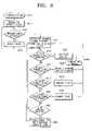
- FIG. 8is a flowchart of the homing step of FIG. 7 ;
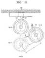
- FIGS. 9 to 11illustrate a docking step in a method for returning a robot to a charger according to a non-limiting embodiment of the present invention.
- FIG. 12is a flowchart showing the exemplary docking step of FIGS. 9 to 11 .
- the robot cleanermay be provided with a power supply, such as a battery (e.g., a rechargeable battery). So that the rechargeable battery may be recharged, the system may further include a charger (e.g., an external charger) to which the robot cleaner may return.
- a power supplysuch as a battery (e.g., a rechargeable battery).
- the systemmay further include a charger (e.g., an external charger) to which the robot cleaner may return.
- the robot cleanermay determine the location of the charger.
- the robot cleanermay also locate the charge terminals so that they may be aligned with the robot's connection terminals.
- FIG. 1Ashows a non-limiting method that may be used to return a robot cleaner to the charger. If the robot cleaner detects a charge request signal, the robot cleaner 11 may approach and move along wall W. If a sensor (e.g., a magnetic sensor), which may be provided on the charger 31 , is detected while the robot cleaner 11 is moving along the wall W, the robot may identify it as a charger and may attempt to dock with it. While this method requires little programming of the robot, it sometimes requires a long period of travel time for the robot. As a result, the robot cleaner battery may become exhausted before the charger is reached.
- a sensore.g., a magnetic sensor
- FIG. 1Bshows another exemplary method by which a robot cleaner 12 may detect and return to charger 32 using a sensor (e.g., an infrared sensor), and may dock with the charger 32 while the robot cleaner 12 is following wall W.
- the robot cleaner 12may randomly travel and detect infrared area A 1 .
- Charger 32may emit infrared light to provide infrared area A 1 .
- the robot cleaner 12may approach and move along a wall W and may dock with the charger 32 .
- the robot cleaner 12may easily approach the charger 32 if the robot cleaner detects infrared area A 1 .
- dockingmay sometimes not be properly achieved.
- FIG. 1Cillustrates yet another exemplary method for guiding a robot cleaner 13 to a charger 33 by providing an infrared sensor on the charger 33 .
- the method shown in FIG. 1Cenables easy performance of the docking operation because infrared area A 2 is defined adjacent the charger 33 .
- the infrared area A 2also may be narrow, it may take a long time for the robot cleaner to find the infrared area A 2 .
- FIG. 1Dillustrates still another non-limiting method of locating a charger.
- the area desired to be cleaned and the position of a chargermay be stored in memory of the robot cleaner 14 (e.g., as map images).
- the robot cleaner 14can return to the charger 34 as soon as a charge desired signal is detected.
- a robot cleaner 100may include body 110 , homing signal receiver 120 , at least one connection terminal 130 , rechargeable battery 140 , a battery charge detector 150 , a distance and angle detector 160 , and a controller 210 .
- the homing signal receiver 120may be provided on the front side of the body 110 , so that the homing signal receiver 120 may receive at least one signal sent by a homing signal transmitter 320 .
- the homing signal receiver 120is adapted to exchange signals with the controller 210 .
- the installation position of the homing signal receiver 120is not limited, it may be preferable that the homing signal receiver 120 be installed at a central part of the front side of the body 110 , as shown in FIG. 3 , so that the homing signal receiver 120 may more effectively receive the signals transmitted from the homing signal transmitter 320 .
- connection terminals 130may be provided on the front surface of the body 110 at a position adapted to effectively engage the charge terminals 330 of charger 300 . It may be preferable that the connection terminals 130 be provided in pairs. Additionally, it may be desirable for the connection terminals to be symmetrical to each other relative to the homing signal receiver 120 .
- the rechargeable battery 140may be installed at body 110 and may be connected to the connection terminals 130 . If connection terminals 130 are plugged into the charge terminals 330 of the charger 300 , the rechargeable battery 140 may be charged.
- the battery charge detector 150may detect the remaining charge of the rechargeable battery 140 .
- the battery charge detector 150may be adapted to exchange signals with controller 210 , so that when the detected charge level is less than a desired level, the battery charge detector 150 may send a charge desired signal to the controller 210 .
- the distance and angle detector 160may detect at least one of the distance and angle between the robot cleaner 100 and the charger 300 when the robot cleaner 100 approaches the charger 300 .
- the distance and angle detector 160may transmit signals to the charger 300 and may receive signals from charger 300 .
- the distance and angle detector 160may be configured to exchange signals with the controller 210 , so that when signals from the charger 300 are detected, the distance and angle detector 160 may send a signal to the controller 210 .
- the distance and angle detector 160can be implemented by one or more infrared light emission devices and an infrared receiver.
- the distance and angle detector 160includes first and second distance angle detection sensors 161 and 162 , which may be positioned at the left and right portions.
- the first and second distance angle detection sensors 161 and 162may be symmetrical to each other about the central part of the front side of the body 110 . That is, the first and second distance detection sensors 161 and 162 may be symmetrically positioned at the left and right portions about the homing signal receiver 120 , as shown in FIG. 3 .
- At least one of the distance and angle detectors 161 , 162detects the distance to the charger 300 .
- At least one of the distance and angle detectors 161 , 162may be configured to have a desired detection range. This range may be set to be, for example, about 10 cm from the charger 300 . Once the robot cleaner 300 enters the desired range, it may be possible for at least one of the distance and angle sensors 161 , 162 to send and/or receive infrared signals to/from the charger 300 .
- the driving unit 170may include wheels (not shown) installed at one or both sides of the body 110 and a motor (not shown) for rotationally driving the wheels.
- the motormay drive the wheels according to control signals received from the controller 210 such that the wheels may be independently rotated in the forward or reverse direction and the revolution rates of the wheels may be different from each other. Accordingly, the robot cleaner 100 may turn right and left and travel forward and backward.
- the robot cleaner 100may be provided with a suction unit for suctioning dirt from a surface to be cleaned, an obstacle detection sensor for detecting an obstacle existing in the travel direction of the robot cleaner 100 , a travel distance detection sensor, as well as other sensors known to those of skill in the art.
- the controller 210may be configured to control components of the robot cleaner 100 so that the robot cleaner 100 cleans. When cleaning is not performed, the controller 210 may control the robot cleaner 100 to standby at the charger 300 so that the rechargeable battery 140 remains charged.
- the controller 210may include a signal discrimination unit 220 and distance and angle calculator 230 .
- the signal discrimination unit 220may discriminate infrared signals received by the homing signal receiver 120 , and may output control codes or digital signals corresponding to the discriminated signals.
- the control codes or digital signalsmay be previously set in the signal discrimination unit 220 .
- the controller 210may control the driving unit 170 using the outputted signals.
- the distance and angle calculator 230may calculate the distance and angle between the robot cleaner 100 and the charger 300 using signals transmitted from the distance and angle detector 160 .
- the distance from at least one of the first and second distance detection sensors 161 and 162 to the charger 300can be determined using the signals which are respectively transmitted from the first and second distance detection sensors 161 and 162 .
- the distance and angle calculator 230can determine the relative positioning of the robot cleaner 100 and the charger 300 and may calculate the angle between the robot cleaner 100 and the charger 300 using the difference between the distance L 1 from the first distance detection sensor 161 to the charger 300 and the distance L 2 from the second distance detection sensor 162 to the charger 300 (see FIG. 10 ).
- the controller 210may drive the driving unit 210 so that the robot cleaner 100 can return to a position adjacent the charger 300 . Meanwhile, using the distance and angle calculated by the distance and angle calculator 230 , the controller 210 may control the driving unit so that the connection terminals 130 of the robot cleaner 100 can be rapidly and precisely connected to the charge terminals 300 of the charger 300 when docking.
- the charger 300may be provided with a homing signal transmitter 320 as well as charge terminals 330 .
- the charge terminals 330may be connected to a power cord 301 (see FIG. 2 ) through an internal transformer, a converter and a power cable.
- the charge terminals 330may be connected to (e.g., plugged into) the connection terminals 130 of the robot cleaner 100 (see FIG. 3 ) to supply power to the rechargeable battery 140 .
- the charge terminals 330may be installed in the charger 300 at approximately the same height as the connection terminals 130 . However, other configurations known to those of skill in the art are also within the scope of the present invention.
- the homing signal transmitter 320may include first, second, third, and fourth signal transmitters 321 , 322 , 323 and 324 . Because the first to fourth signal transmitters 321 to 324 transmit signals that may be different from each other in code, the signal discrimination unit may be configured to discriminate the respective signals transmitted by the first to fourth signal transmitters 321 to 324 .
- the first to third signal transmitters 321 to 323may be provided on the front side of the charger 300 and the fourth signal transmitter 324 may be provided at a side of the charger 300 .
- the first to fourth signal transmitters 321 to 324include infrared light emission devices such as infrared LEDs. In this case, an infrared receiver may be employed in the homing signal receiver 120 . By employing infrared light emission devices and an infrared receiver, the system for returning a robot cleaner to a charger can be relatively inexpensively implemented.
- a single homing signal receiver 120may reduce costs and the space required for installing the homing signal receiver 120 . Therefore, it may be preferable for the first to fourth signal transmitters 321 to 324 to transmit infrared signals having the same or approximately the same frequency.
- the infrared signalswhich may be transmitted from each of the first, second, and third signal transmitters 321 , 322 , and 323 , may be different from each other in signal transmission angle and distance.
- An object of the present inventionis to enable the robot cleaner 100 to receive infrared signals, and to rapidly approach the charger 300 using the signals.
- the infrared signalsmay vary with respect to the pattern of high and low voltages alternating in the signal per second.
- the first transmittermay send a signal including three high voltages alternated with three low voltages
- the second transmittermay send a signal including four high voltages alternated with four low voltages.
- these examplesare non-limiting, and other signals are within the scope of this invention.
- these signalsare referred to herein as “different in code.”
- the signal transmission distances and anglesmay be gradually reduced in the order of the first signal transmitter 321 , the second signal transmitter 322 , and the third signal transmitter 323 .
- These signal transmission distances and anglesmay be set as default values during manufacturing.
- by providing adjustment grips on at least one side of the first to third signal transmitters 321 to 323it may be possible to precisely adjust the signal transmission angles.
- the first and second signal transmitters 321 and 322be vertically arranged at or near the central part of the charger 300 .
- the signal transmission angle and distance of the third signal transmitter 323may be small, it may be desirable to provide two signal transmitters for the third signal transmitter 323 .
- These transmittersmay be arranged at opposite lateral sides of the charger 300 to be symmetrical to each other about the first and second signal transmitters 321 and 322 .
- a possible configuration of the system of the present inventionmay include the charger installed at a wall.
- the robot cleaner 100may not detect an infrared signal transmitted from the first to third signal transmitters 321 to 323 when the robot cleaner 100 travels along the wall on which the charger 300 is installed. Therefore, it may be desirable to provide two signal transmitters for the fourth signal transmitter 324 at opposite lateral sides of the charger 300 .
- the fourth signal transmitter 324may also transmit a signal having a code which is different from those of the infrared signals sent by the first to third signal transmitters 321 to 323 .
- the robot cleaner 100may standby in a state in which the connection terminals 130 of the robot cleaner 100 are connected to the charge terminals 330 of the charger 300 .
- the robot cleaner 100separates from the charger 300 and cleans an area determined by at least one of a user's command or a previously programmed command.
- the controller 210may change the mode of the robot cleaner 100 into a return mode, so that the robot cleaner returns to the charger 300 . That is, the controller 210 may control the robot cleaner 100 so that the robot cleaner 100 travels from its position to receive signals sent by the homing signal transmitter 320 of the charger 300 . For example, the robot cleaner 100 may travel in a zigzag pattern, randomly, or following the wall W (on which the charger 300 is provided) until infrared signals sent by the homing signal transmitter 320 are received by the homing signal receiver 120 .
- the exemplary method for returning and docking the robot cleaner 100 with the charger 300can be divided into two steps: a homing step (in which the robot cleaner 100 is guided to approach the charger 300 ) and a docking step (in which the connection terminals 130 of the robot cleaner 100 is connected to the charge terminals 330 of the charger 300 ).
- the homing stepis described with reference to FIGS. 7 and 8 .
- the robot cleaner 100starts homing (S 410 ) and searches for an infrared signal while traveling (S 411 ).
- the robot cleaner 100may continuously travel until homing signal receiver 120 (see FIG. 3 ) detects infrared signals (S 413 ).
- the infrared signalswhich may be transmitted from the first to fourth signal transmitters 321 to 324 , are referred to as first, second, third, and fourth signals A 321 , A 322 , A 323 , and A 324 , respectively.
- the robot cleaner 100may turn without making progress, so that the homing signal receiver 120 may locate another infrared signal, the code of which may be different from the previously detected infrared signal (S 414 ). Because the signal transmission angle and distance of the first infrared signal A 321 are the largest among the first to fourth infrared signals, the homing signal receiver 120 generally initially detects the first infrared signal A 321 . Therefore, if the first infrared signal A 321 is detected, the robot cleaner 100 searches to find the second to fourth infrared signals A 322 to A 324 . Meanwhile, because it is an object of the present invention to enable the robot cleaner 100 to rapidly and precisely approach the charger 300 , the robot cleaner 100 may continuously search until the third infrared signal A 323 is detected.
- the robot cleaner 100 - 3may enter the docking step S 416 , and may terminate the homing step (S 416 A).
- the robot cleaner 100 - 4may move toward the forward area of the charger 300 . To do this, the robot cleaner 100 - 4 may turn left or right by 90° as indicated by arrows C and D before moving forward.
- the fourth infrared signal A 324may be transmitted from the lateral sides of the charger 300 . As described above, the transmission distance of the fourth infrared signal A 324 may be relatively short (about 1 m), and the transmission angle may be relatively wide. Therefore, an effective path for detecting the third infrared signal A 323 may be obtained if the robot cleaner turns left or right by 90° and travels straight, as shown in FIG. 7 .
- the robot cleaner 1004may travel toward the front area of the charger 300 , which emits the third infrared signal A 323 . Therefore, the robot cleaner could rapidly detect the third infrared signal A 323 .
- the robot cleaner 100 - 2may be caused to move toward the front area of the charger 300 (which emits the signals) as indicated by arrow E (S 420 ).
- the robot cleanerdetects the first infrared signal A 321 without detecting the second to fourth infrared signals A 322 to A 324 (S 421 ), the robot cleaner 100 - 1 is caused to move toward the front area of the charger 300 as indicated by arrow F (S 422 ).
- the infrared signals transmitted from the respective signal transmittersmay each have a fan-shape transmission area as shown in the drawing, the reception sensitivity of infrared signals may be highest for an infrared signal transmitted from the original signal source. Because the first and second signal transmitters 321 and 322 may be provided at the central part of the front side of the charger 300 and the homing signal reception part 120 may be positioned at the center of the front side of the robot cleaner 100 , thereby receiving the first and second infrared signals A 321 and A 322 , the robot cleaner may most effectively approach the central part of the front of the charger 300 .
- the robot cleanermay travel toward the charger 300 for a desired length of time (S 424 ) and may continuously search until the third infrared signal A 323 is detected.
- the desired length of timemay be predetermined based on a variety of factors, including anticipated battery life.
- the homing signal receiver 120 of the robot cleaner 100may receive a plurality of infrared signals, which may be different from each other in code, signal transmission angle, and signal transmission distance.
- the controller 210(see FIG. 4 ) may prioritize the respective received infrared signals. That is, the controller 210 may prioritize the received infrared signals in the order of the third infrared signal A 323 , the fourth infrared signal A 324 , the second infrared signal A 322 , and the first infrared signal A 321 . If two or more different infrared signals are received, the controller 210 may control the robot cleaner 100 to travel based on the highest priority level of the received signals.
- At least one infrared signal transmitterwhich may be different in signal transmission angle and distance from another infrared signal transmitter, may be provided at the charger 300 , the controller 210 may calculate an effective (even optimal) path depending on the distance between the robot cleaner 100 and the charger 300 .
- the controller 210may calculate an effective (even optimal) path depending on the distance between the robot cleaner 100 and the charger 300 .
- the process and algorithm for returning the robot cleaner 100 to the charger 300are simple, manufacturing costs may be reduced.
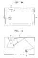
- FIGS. 9 to 11the respective signal transmitters 321 to 324 (see FIG. 5A ) provided in the charger 300 are omitted in FIGS. 9 to 11 .
- the robot cleaner 100may move to a position spaced from the charger 300 by a predetermined distance (e.g., about 10 cm) (S 431 ).
- the predetermined distancecan be calculated by the first and second distance detection sensors 161 and 162 which may be provided in the robot cleaner 100 .
- the first and second distance detection sensors 161 and 162may each transmit infrared signals to the charger 300 and may receive the infrared signals reflected from the charger 300 .
- the velocity of the infrared signalsis fixed, it is possible to calculate the respective distances L 1 and L 2 from the first and second distance detection sensors 161 and 162 to the charger using the time elapsed between the transmitted infrared signals and the received infrared signals. It is possible to use the larger or smaller of the distances L 1 and L 2 or the mean of L 1 and L 2 .
- the controller 210may determine if the robot cleaner 100 and the charger 300 are substantially parallel to each other (S 432 ). Such a determination may be made by comparing the values of L 1 and L 2 . For example, if the calculated distances L 1 and L 2 are identical to each other, the robot cleaner 100 and the charger 300 may be parallel to each other. If not, the robot cleaner 100 and the charger 300 may not be parallel to each other. However, because it is unlikely that L 1 and L 2 would be completely identical, it may be desirable to define a range of tolerance for each of the values L 1 and L 2 . If the calculated values of L 1 and L 2 are substantially identical within the ranges of tolerance, it is effective to determine that the robot cleaner 100 and the charger 300 are substantially parallel to each other.
- the distance and angle calculator 230may calculate the angle between the robot cleaner 100 and the charger 300 (S 433 ).
- the anglecan be calculated using the distance L 1 from the first distance detection sensor 161 to the charger 300 and the distance L 2 from the second detection sensor 162 to the charger 300 as follows.
- Ksqrt( H ⁇ 2 +W ⁇ 2) (1)
- the robot cleaner 100 - 6may turn in the direction in which the homing signal receiver 120 rotates away from the center line of the charger 300 (i.e., in a clockwise direction in FIG. 11 ) by an angle equal to about twice the calculated angle ⁇ as indicated in FIG. 11 (S 434 ). Then, the robot cleaner 100 - 6 may travel straight back by distance N so that the center point of the robot cleaner 100 - 6 and the central line of the charger 300 are in line with each other (S 435 ).
- the value of Mis an approximate value.
- the connection terminals of the robot cleaner 100 and the charge terminals 330 of the charger 300may be configured such that they can be joined with each other even if they are correctly aligned with each other.
- the connection terminals 130 of the robot cleaner 100may protrude from the front surface of the robot cleaner 100 .
- the approximate valuemay be different from the real value.
- the differenceis generally not large and the connection terminals 130 and the charge terminals 330 can generally still be joined with each other.
- the extension line from the center point O of the robot cleaner 100 and the center point P of the charger 300may be in line with each other when the robot cleaner 100 and the charger 300 are not parallel to each other as shown in FIG. 10 .
- the extension line and the center point Pmay not be in line with each other. Even if such an error is produced, it can be neglected and the connection terminals 130 and the charge terminals 330 can be joined with each other. If the error is large, the determination as to if the robot cleaner 100 and the charger 300 are parallel to each other may be performed again as described below.
- the robot cleaner 100 - 7may turn in a direction in which the homing signal receiver 120 rotates toward the central line of the charger 300 (i.e., in a counter-clockwise direction in FIG. 11 ) by ⁇ (S 436 ). Then, the robot cleaner 100 - 7 and the charger 300 may become parallel to each other. Then, the robot cleaner 100 - 8 may travel straight so that it approaches the charger 300 to a distance of about 10 cm from the charger 300 , thereby performing the step S 431 again.
- the robot cleaner 100may attempt to dock so that the connection terminals 130 can be connected with the charge terminals (S 437 ). Then, it may be determined if the docking has been completed (S 438 ). If the docking is completed (i.e., if the connection terminals 130 and the charge terminals 330 are joined with each other), the docking operation may be terminated (S 440 ). However, if the docking is not completed (i.e., if the connection terminals 130 and the charge terminals 330 are correctly joined with each other), the robot cleaner may travel back about 15 cm (S 439 ) and may repeatedly perform step S 431 .
Landscapes
- Engineering & Computer Science (AREA)
- Physics & Mathematics (AREA)
- Aviation & Aerospace Engineering (AREA)
- Radar, Positioning & Navigation (AREA)
- Remote Sensing (AREA)
- General Physics & Mathematics (AREA)
- Automation & Control Theory (AREA)
- Mechanical Engineering (AREA)
- Electromagnetism (AREA)
- Control Of Position, Course, Altitude, Or Attitude Of Moving Bodies (AREA)
- Electric Vacuum Cleaner (AREA)
Abstract
Description
K=sqrt(H^2+W^2) (1)
θ=90°−G (2)
M=(L1+L2)/2 (3)
N=M+R. (4)
Claims (17)
Applications Claiming Priority (3)
| Application Number | Priority Date | Filing Date | Title |
|---|---|---|---|
| KR10-2005-0080977 | 2005-08-31 | ||
| KR2005-80977 | 2005-08-31 | ||
| KR1020050080977AKR100645381B1 (en) | 2005-08-31 | 2005-08-31 | External charge return device and return method for robot cleaner |
Publications (2)
| Publication Number | Publication Date |
|---|---|
| US20070050086A1 US20070050086A1 (en) | 2007-03-01 |
| US7729803B2true US7729803B2 (en) | 2010-06-01 |
Family
ID=37507438
Family Applications (1)
| Application Number | Title | Priority Date | Filing Date |
|---|---|---|---|
| US11/486,284Active2028-12-07US7729803B2 (en) | 2005-08-31 | 2006-07-14 | System and method for returning robot cleaner to charger |
Country Status (6)
| Country | Link |
|---|---|
| US (1) | US7729803B2 (en) |
| EP (1) | EP1760564B1 (en) |
| JP (1) | JP4171753B2 (en) |
| KR (1) | KR100645381B1 (en) |
| CN (1) | CN100579732C (en) |
| RU (1) | RU2338639C9 (en) |
Cited By (22)
| Publication number | Priority date | Publication date | Assignee | Title |
|---|---|---|---|---|
| US20070233319A1 (en)* | 2006-03-29 | 2007-10-04 | Lg Electronics Inc. | System and method for returning mobile robot to charging stand |
| US20080161969A1 (en)* | 2006-12-28 | 2008-07-03 | Industrial Technology Research Institute | Method for routing a robotic apparatus to a service station and robotic apparatus service system using thereof |
| US20100211243A1 (en)* | 2004-03-05 | 2010-08-19 | Samsung Electronics Co., Ltd. Of Suwon-Si | Traveling control method, medium, and apparatus for autonomous navigation |
| US20120143428A1 (en)* | 2009-06-30 | 2012-06-07 | Bong-Ju Kim | Charging device of robot cleaner |
| US20120197434A1 (en)* | 2011-01-28 | 2012-08-02 | Ho Yueh-Sheng | Robot control system and method |
| CN103507067A (en)* | 2012-06-15 | 2014-01-15 | 华硕电脑股份有限公司 | Robotic device and method for guiding robot back to base station |
| TWI447548B (en)* | 2011-07-15 | 2014-08-01 | Uni Ring Tech Co Ltd | Method of returning to charging station for charging for self-propelled mobile device and the system thereof |
| US20150134144A1 (en)* | 2012-06-07 | 2015-05-14 | Koninklijke Philips N.V. | System and method for guiding a robot cleaner along a path |
| US20170047765A1 (en)* | 2015-08-13 | 2017-02-16 | Samsung Electronics Co., Ltd. | Electronic device and method for wireless charging in electronic device |
| US20170136881A1 (en)* | 2015-11-13 | 2017-05-18 | NextEv USA, Inc. | Vehicle to vehicle charging system and method of use |
| US20180004212A1 (en)* | 2014-11-07 | 2018-01-04 | Ecovacs Robotics Co., Ltd. | Guide-Type Virtual Wall System |
| US20180034294A1 (en)* | 2016-07-29 | 2018-02-01 | Hon Hai Precision Industry Co., Ltd. | Charging device and charging system |
| US9904283B2 (en) | 2016-03-08 | 2018-02-27 | Fuji Xerox Co., Ltd. | Systems and methods employing coded light to dock aerial drones, self-driving cars and surface robots |
| US10220717B2 (en) | 2015-11-13 | 2019-03-05 | Nio Usa, Inc. | Electric vehicle emergency charging system and method of use |
| US10532663B2 (en) | 2015-11-13 | 2020-01-14 | Nio Usa, Inc. | Electric vehicle overhead charging system and method of use |
| US20200022552A1 (en)* | 2017-03-23 | 2020-01-23 | Lg Electronics Inc. | Cleaner and method of controlling the same |
| US10632852B2 (en) | 2015-11-13 | 2020-04-28 | Nio Usa, Inc. | Electric vehicle optical charging system and method of use |
| US10698417B2 (en) | 2016-05-06 | 2020-06-30 | Mtd Products Inc | Autonomous mower navigation system and method |
| US20210146552A1 (en)* | 2019-11-20 | 2021-05-20 | Samsung Electronics Co., Ltd. | Mobile robot device and method for controlling mobile robot device |
| US11583158B2 (en) | 2018-08-01 | 2023-02-21 | Sharkninja Operating Llc | Robotic vacuum cleaner |
| US11627854B2 (en) | 2018-10-22 | 2023-04-18 | Sharkninja Operating Llc | Docking station for robotic cleaner |
| US11950755B2 (en) | 2018-06-14 | 2024-04-09 | Samsung Electronics Co., Ltd. | Charging station for robot vacuum cleaner |
Families Citing this family (90)
| Publication number | Priority date | Publication date | Assignee | Title |
|---|---|---|---|---|
| KR100645381B1 (en)* | 2005-08-31 | 2006-11-14 | 삼성광주전자 주식회사 | External charge return device and return method for robot cleaner |
| KR100758038B1 (en)* | 2006-11-22 | 2007-09-11 | 삼성광주전자 주식회사 | How to charge the robot cleaner |
| KR100850227B1 (en) | 2007-03-29 | 2008-08-04 | 엘지전자 주식회사 | Mobile robot return system and its operation method |
| WO2008149273A2 (en)* | 2007-06-05 | 2008-12-11 | Koninklijke Philips Electronics N.V. | A system as well as a method for controlling a self moving robot |
| JP2009012668A (en)* | 2007-07-06 | 2009-01-22 | Sharp Corp | Controller and mobile robot system using the same |
| KR100860843B1 (en)* | 2007-08-14 | 2008-09-29 | 주식회사 에스코드 | Autonomous driving device and method, and autonomous vehicle using same |
| KR101198773B1 (en) | 2008-01-23 | 2012-11-12 | 삼성전자주식회사 | Returning Method of Robot Cleaner System |
| SE534240C2 (en)* | 2008-12-05 | 2011-06-14 | Datachassi Dc Ab | Procedure and systems for providing docking assistance |
| GB0909148D0 (en)* | 2009-05-28 | 2009-07-01 | F Robotics Acquisitions Ltd | Localisation system |
| KR101406186B1 (en)* | 2009-11-18 | 2014-06-13 | 삼성전자주식회사 | Control method of robot cleaner |
| EP2547191B1 (en)* | 2010-03-17 | 2018-09-19 | Husqvarna AB | Method and system for guiding a robotic garden tool to a predetermined position |
| KR101662081B1 (en)* | 2010-08-20 | 2016-10-04 | 엘지전자 주식회사 | A vacuum cleaner |
| WO2012036586A1 (en) | 2010-09-14 | 2012-03-22 | Общество С Ограниченной Ответственностью Компания "Норкпалм" | Automated system for cleaning a building |
| DE102010042227A1 (en)* | 2010-10-08 | 2012-04-12 | Robert Bosch Gmbh | Method and charging station for electrically charging an electrical energy store |
| US9502907B2 (en)* | 2010-12-10 | 2016-11-22 | Hayward Industries, Inc. | Power supplies for pool and spa equipment |
| US8515580B2 (en)* | 2011-06-17 | 2013-08-20 | Microsoft Corporation | Docking process for recharging an autonomous mobile device |
| KR101639669B1 (en)* | 2011-12-09 | 2016-07-14 | 한화테크윈 주식회사 | Method for controlling motor |
| CN103259302A (en)* | 2012-02-16 | 2013-08-21 | 恩斯迈电子(深圳)有限公司 | Charging station and charging system |
| CN103251360A (en) | 2012-02-16 | 2013-08-21 | 恩斯迈电子(深圳)有限公司 | Control method of sweeping robot |
| CN103251355A (en)* | 2012-02-16 | 2013-08-21 | 恩斯迈电子(深圳)有限公司 | Sweeping robot and charging system |
| CN103251358A (en)* | 2012-02-16 | 2013-08-21 | 恩斯迈电子(深圳)有限公司 | Control method of sweeping robot |
| TW201338745A (en)* | 2012-03-23 | 2013-10-01 | Ememe Robot Co Ltd | A controlling system of a robot and method for controlling a robot |
| CN103365291B (en)* | 2012-03-29 | 2016-02-17 | 凌海科技企业股份有限公司 | Control unit and method for directing self-propelled device to charging stand |
| US9538892B2 (en) | 2012-10-05 | 2017-01-10 | Irobot Corporation | Robot management systems for determining docking station pose including mobile robots and methods using same |
| US20140222271A1 (en)* | 2013-02-07 | 2014-08-07 | MetraLabs Automation, Inc. | Autonomous mobile robot inductive charging system |
| EP2959348B1 (en)* | 2013-02-20 | 2018-09-19 | Husqvarna AB | A robotic work tool system and method comprising a charging station |
| JP5939266B2 (en)* | 2014-02-21 | 2016-06-22 | トヨタ自動車株式会社 | MOBILE BODY CONTROL SYSTEM, MOBILE BODY CONTROL METHOD, PROGRAM |
| KR20160127013A (en)* | 2014-02-25 | 2016-11-02 | 알프레드 캐르혀 게엠베하 운트 컴파니. 카게 | Method for docking a floor treatment device to a base station, and floor treatment system |
| JP6393520B2 (en)* | 2014-05-23 | 2018-09-19 | シャープ株式会社 | Self-propelled electronic device |
| KR101620449B1 (en) | 2014-06-26 | 2016-05-12 | 삼성전자 주식회사 | Robot cleaner and method for controlling the same |
| DE102014212408A1 (en) | 2014-06-27 | 2015-12-31 | Robert Bosch Gmbh | Autonomous working device |
| CN106535729A (en)* | 2014-06-30 | 2017-03-22 | 松下知识产权经营株式会社 | Autonomous travel-type cleaner |
| KR102180548B1 (en)* | 2014-07-15 | 2020-11-18 | 엘지전자 주식회사 | Docking station and Robot cleaning system including the same |
| JP6325946B2 (en) | 2014-08-27 | 2018-05-16 | 東芝ライフスタイル株式会社 | Autonomous vehicle |
| CN105629971A (en)* | 2014-11-03 | 2016-06-01 | 贵州亿丰升华科技机器人有限公司 | Robot automatic charging system and control method therefor |
| CN104765379B (en)* | 2014-11-11 | 2018-01-09 | 深圳市银星智能科技股份有限公司 | Robot finds the method and robot system for recharging seat in closing working region |
| KR102404258B1 (en) | 2015-02-06 | 2022-06-02 | 삼성전자주식회사 | Apparatus for returning of robot and returning method thereof |
| KR101659037B1 (en)* | 2015-02-16 | 2016-09-23 | 엘지전자 주식회사 | Robot cleaner, remote controlling system and method of the same |
| CN104723344A (en)* | 2015-03-17 | 2015-06-24 | 江门市东方智慧物联网科技有限公司 | Smart home service robot system |
| CN104950889A (en)* | 2015-06-24 | 2015-09-30 | 美的集团股份有限公司 | Robot charging stand and robot provided with same |
| US9919425B2 (en)* | 2015-07-01 | 2018-03-20 | Irobot Corporation | Robot navigational sensor system |
| JP6636289B2 (en)* | 2015-09-29 | 2020-01-29 | 東芝ライフスタイル株式会社 | Traveling device |
| WO2017084395A1 (en) | 2015-11-20 | 2017-05-26 | 江苏美的清洁电器股份有限公司 | System for cleaning robot to return to charge and return charge control method therefor |
| CN105242674B (en)* | 2015-11-20 | 2017-03-08 | 江苏美的清洁电器股份有限公司 | Sweeping robot recharges electric system and its recharges control method |
| CN105511473A (en)* | 2016-01-08 | 2016-04-20 | 莱克电气股份有限公司 | Robot charging seat and method for guiding robot to return to charging |
| SE539613C2 (en) | 2016-01-11 | 2017-10-17 | Husqvarna Ab | Self-propelled robotic tool navigation |
| CN105487543A (en)* | 2016-01-13 | 2016-04-13 | 浙江瓦力泰克智能机器人科技有限公司 | Movable robot homing and charging system |
| CN105446344A (en)* | 2016-01-13 | 2016-03-30 | 浙江瓦力泰克智能机器人科技有限公司 | Mobile robot homing charge and payment system |
| CN107198499B (en)* | 2016-03-18 | 2021-03-05 | 松下电器(美国)知识产权公司 | Autonomous moving apparatus, autonomous moving method, and autonomous moving system |
| CN107437830B (en)* | 2016-05-27 | 2021-01-01 | 华硕电脑股份有限公司 | Automatic walking device and control method thereof |
| JP6571051B2 (en)* | 2016-07-14 | 2019-09-04 | 日立グローバルライフソリューションズ株式会社 | Autonomous traveling vacuum cleaner system and charging stand |
| CN106308685B (en)* | 2016-08-23 | 2019-10-11 | 北京小米移动软件有限公司 | cleaning robot and control method thereof |
| CN106569495A (en)* | 2016-11-11 | 2017-04-19 | 青岛众海汇智能源科技有限责任公司 | Positioning system and method for wireless charging sweeping machine |
| US10698411B1 (en) | 2016-12-13 | 2020-06-30 | AI Incorporated | Recharge station for mobile robot |
| KR101849972B1 (en)* | 2016-12-27 | 2018-05-31 | 엘지전자 주식회사 | Robot cleaner and method for controlling the saem |
| CN107124014A (en)* | 2016-12-30 | 2017-09-01 | 深圳市杉川机器人有限公司 | The charging method and charging system of a kind of mobile robot |
| KR101984101B1 (en)* | 2017-03-06 | 2019-05-30 | 엘지전자 주식회사 | Cleaner and controlling method thereof |
| CN106931528A (en)* | 2017-03-08 | 2017-07-07 | 苏州立瓷智能电器有限公司 | A kind of Intellectual air cleaner device people |
| JP6624139B2 (en)* | 2017-03-24 | 2019-12-25 | カシオ計算機株式会社 | Autonomous mobile device, autonomous mobile method and program |
| CN106877454B (en)* | 2017-04-06 | 2024-05-10 | 上海诺亚木木机器人科技有限公司 | Robot charging method and device |
| CN107272745A (en)* | 2017-06-20 | 2017-10-20 | 深圳市艾特智能科技有限公司 | Robot recharges control method |
| CN107390685B (en)* | 2017-07-14 | 2020-10-16 | 深圳市优必选科技有限公司 | Robot recharging control method, robot and robot system |
| TWI645276B (en)* | 2017-08-30 | 2018-12-21 | 世擘股份有限公司 | Automatic charging method and cleaning robot |
| CN114343487B (en)* | 2017-09-25 | 2023-10-27 | 北京石头创新科技有限公司 | Automatic cleaning device, automatic cleaning system and charging method thereof |
| JP7107658B2 (en)* | 2017-10-11 | 2022-07-27 | 日立グローバルライフソリューションズ株式会社 | AUTONOMOUS RUNNING VACUUM CLEANER, AUTONOMOUS RUNNING TYPE VACUUM CLEANER SYSTEM, AND MOVING OBJECT |
| CN107898387B (en)* | 2017-10-16 | 2021-04-27 | 深圳市艾特智能科技有限公司 | Recharge control method and system, readable storage medium and intelligent device |
| KR102203439B1 (en)* | 2018-01-17 | 2021-01-14 | 엘지전자 주식회사 | a Moving robot and Controlling method for the moving robot |
| WO2019183907A1 (en)* | 2018-03-30 | 2019-10-03 | Changzhou Globe Co.,Ltd | Robotic mower and method for controlling a robotic mower |
| CN108615352A (en)* | 2018-04-27 | 2018-10-02 | 杭州艾豆智能科技有限公司 | A kind of method that multiple signals synchronize signaling |
| US10317517B1 (en)* | 2018-05-15 | 2019-06-11 | Delphi Technologies, Llc | Vehicle location device |
| CA3104486A1 (en) | 2018-06-20 | 2019-12-26 | Hayward Industries, Inc. | Power supplies for pool and spa equipment |
| CN109038724A (en)* | 2018-08-01 | 2018-12-18 | 安克创新科技股份有限公司 | Robot charging device |
| KR102291884B1 (en)* | 2018-08-03 | 2021-08-20 | 엘지전자 주식회사 | Moving robot and contorlling method thereof |
| KR102242713B1 (en) | 2018-08-03 | 2021-04-22 | 엘지전자 주식회사 | Moving robot and contorlling method and a terminal |
| CN109002043B (en)* | 2018-08-24 | 2021-06-15 | 湖南超能机器人技术有限公司 | Infrared alignment signal data processing method applied to robot |
| CN209400715U (en)* | 2018-08-24 | 2019-09-17 | 北京猎户星空科技有限公司 | Infrared launcher and charging pile |
| CN110893085B (en)* | 2018-09-11 | 2021-12-31 | 原相科技股份有限公司 | Cleaning robot and charging path determining method thereof |
| CN113365535B (en) | 2018-12-03 | 2023-01-06 | 尚科宁家运营有限公司 | Optical marker for communicating information to autonomous device |
| CN109955266B (en)* | 2019-04-01 | 2020-12-15 | 珠海市一微半导体有限公司 | Automatic generation equipment and automatic generation system for robot backseat code |
| US11598838B2 (en) | 2019-06-26 | 2023-03-07 | Aptiv Technologies Limited | Detection device |
| CN112748727B (en)* | 2019-10-31 | 2024-07-12 | 珠海一微半导体股份有限公司 | Navigation control method using target point, chip and robot |
| KR102275083B1 (en)* | 2019-12-05 | 2021-07-08 | 주식회사 제타뱅크 | Robotic systems and a returning method of robot for automatic charging |
| CN111781930B (en)* | 2020-07-10 | 2022-12-20 | 广州今甲智能科技有限公司 | Method for accurately positioning charging pile by intelligent robot and intelligent robot |
| US12064082B2 (en)* | 2020-08-14 | 2024-08-20 | Samsung Electronics Co., Ltd. | Cleaning robot and controlling method thereof |
| EP3968051B1 (en)* | 2020-09-15 | 2024-10-30 | Infineon Technologies AG | Guiding system for a robot, base station including such a guiding system, and method for guiding a robot |
| CN115129036A (en)* | 2021-03-26 | 2022-09-30 | 信泰光学(深圳)有限公司 | Mobile device and method for moving the same |
| CN115509218B (en)* | 2021-06-22 | 2024-10-18 | 速感科技(北京)有限公司 | Automatic recharging method and system for autonomous mobile equipment |
| CN113534805B (en)* | 2021-07-19 | 2024-04-19 | 美智纵横科技有限责任公司 | Robot recharging control method, device and storage medium |
| CN114103703B (en)* | 2021-11-19 | 2024-08-13 | 上海擎朗智能科技有限公司 | Automatic charging method, mobile charging device and automatic charging system |
| CN114442624B (en)* | 2022-01-21 | 2022-12-23 | 美的集团(上海)有限公司 | Robot recharging control method, device and system |
Citations (40)
| Publication number | Priority date | Publication date | Assignee | Title |
|---|---|---|---|---|
| GB2178881A (en) | 1983-12-27 | 1987-02-18 | Casio Computer Co Ltd | Mobile robot calling system |
| US4679152A (en)* | 1985-02-20 | 1987-07-07 | Heath Company | Navigation system and method for a mobile robot |
| US4777416A (en)* | 1986-05-16 | 1988-10-11 | Denning Mobile Robotics, Inc. | Recharge docking system for mobile robot |
| US4835692A (en)* | 1986-02-05 | 1989-05-30 | Bridge & Plate Construction Pty. Ltd. | Remote controlled travel apparatus |
| JPH01163610A (en) | 1987-12-21 | 1989-06-27 | Meidensha Corp | Position detecting device for unmanned vehicle |
| US4892701A (en)* | 1986-11-20 | 1990-01-09 | Framatome | Device for measuring nuclear reactor fuel assembly grids |
| JPH02209121A (en) | 1989-02-08 | 1990-08-20 | Matsushita Electric Ind Co Ltd | self-propelled vacuum cleaner |
| JPH0546239A (en) | 1991-08-10 | 1993-02-26 | Nec Home Electron Ltd | Autonomously travelling robot |
| JPH0795146A (en) | 1993-09-22 | 1995-04-07 | Daifuku Co Ltd | Moving vehicle operation control installation |
| US5440216A (en)* | 1993-06-08 | 1995-08-08 | Samsung Electronics Co., Ltd. | Robot cleaner |
| US5534762A (en)* | 1993-09-27 | 1996-07-09 | Samsung Electronics Co., Ltd. | Self-propelled cleaning robot operable in a cordless mode and a cord mode |
| US5568589A (en)* | 1992-03-09 | 1996-10-22 | Hwang; Jin S. | Self-propelled cleaning machine with fuzzy logic control |
| US5787545A (en)* | 1994-07-04 | 1998-08-04 | Colens; Andre | Automatic machine and device for floor dusting |
| US5926909A (en) | 1996-08-28 | 1999-07-27 | Mcgee; Daniel | Remote control vacuum cleaner and charging system |
| US6278917B1 (en)* | 1997-09-01 | 2001-08-21 | Siemens Aktiengesellschaft | Method for docking an autonomous mobile unit with the use of a light beam |
| US20020041176A1 (en)* | 2000-09-29 | 2002-04-11 | Yutaka Eki | Battery apparatus for charging portable device |
| US20020052671A1 (en) | 1999-11-29 | 2002-05-02 | Carpenter Kipley Tad | Automated data storage library with wireless robotic positioning system |
| US6389329B1 (en)* | 1997-11-27 | 2002-05-14 | Andre Colens | Mobile robots and their control system |
| US20020120364A1 (en)* | 1997-11-27 | 2002-08-29 | Andre Colens | Mobile robots and their control system |
| US6459955B1 (en)* | 1999-11-18 | 2002-10-01 | The Procter & Gamble Company | Home cleaning robot |
| US6496755B2 (en)* | 1999-11-24 | 2002-12-17 | Personal Robotics, Inc. | Autonomous multi-platform robot system |
| JP2003001577A (en) | 2001-06-25 | 2003-01-08 | Sony Corp | Charge equipment, robot system and charge control method |
| US20030060928A1 (en)* | 2001-09-26 | 2003-03-27 | Friendly Robotics Ltd. | Robotic vacuum cleaner |
| US6690134B1 (en)* | 2001-01-24 | 2004-02-10 | Irobot Corporation | Method and system for robot localization and confinement |
| GB2394796A (en) | 2002-10-31 | 2004-05-05 | Samsung Kwangju Electronics Co | Docking robot cleaner system with external charger |
| JP2004151924A (en) | 2002-10-30 | 2004-05-27 | Sony Corp | Autonomous mobile robot and control method for the same |
| KR20040053653A (en) | 2002-12-17 | 2004-06-24 | 엘지전자 주식회사 | Charging guide apparatus of robot cleaner |
| KR20040063247A (en) | 2003-01-06 | 2004-07-14 | 엘지전자 주식회사 | Auto charge return apparatus and method of robot cleaner |
| US20040158357A1 (en) | 2003-02-06 | 2004-08-12 | Samsung Gwangju Electronics Co., Ltd | Robot cleaner system having external recharging apparatus and method for docking robot cleaner with external recharging apparatus |
| EP1457151A2 (en) | 2003-03-14 | 2004-09-15 | Lg Electronics Inc. | Automatic battery charging system and method of robot cleaner |
| JP2004326692A (en) | 2003-04-28 | 2004-11-18 | Toshiba Tec Corp | Autonomous mobile robot |
| US20050010330A1 (en)* | 2003-07-11 | 2005-01-13 | Shai Abramson | Autonomous machine for docking with a docking station and method for docking |
| US20050150074A1 (en)* | 2002-07-08 | 2005-07-14 | Alfred Kaercher Gmbh & Co. Kg | Floor treatment system |
| US20050156562A1 (en)* | 2004-01-21 | 2005-07-21 | Irobot Corporation | Autonomous robot auto-docking and energy management systems and methods |
| US20050168345A1 (en)* | 2004-02-03 | 2005-08-04 | Rtc Industries, Inc. | System for inventory management |
| US6977618B1 (en)* | 2003-12-05 | 2005-12-20 | L3 Communications Corporation | Aircraft folding antenna assembly |
| US20060087273A1 (en) | 2004-10-27 | 2006-04-27 | Samsung Gwangju Electronics Co., Ltd | Robot cleaner system and a method for returning to external recharging apparatus |
| US20070050086A1 (en)* | 2005-08-31 | 2007-03-01 | Samsung Gwangju Electronics Co., Ltd. | System and method for returning robot cleaner to charger |
| US7343221B2 (en)* | 2003-07-31 | 2008-03-11 | Samsung Electronics Co., Ltd. | Control system of a robot cleaner |
| US20080105185A1 (en)* | 2006-02-02 | 2008-05-08 | Kuhlman Clare J | Tug barge lightering connection system |
Family Cites Families (2)
| Publication number | Priority date | Publication date | Assignee | Title |
|---|---|---|---|---|
| KR100437362B1 (en)* | 2001-08-06 | 2004-06-25 | 삼성광주전자 주식회사 | External charging apparatus of robot cleaner and system employing the same |
| KR100486506B1 (en)* | 2002-12-31 | 2005-04-29 | 엘지전자 주식회사 | Auto charge apparatus and method of robot cleaner in using image processing |
- 2005
- 2005-08-31KRKR1020050080977Apatent/KR100645381B1/ennot_activeExpired - Fee Related
- 2006
- 2006-06-09JPJP2006160648Apatent/JP4171753B2/ennot_activeExpired - Fee Related
- 2006-07-14USUS11/486,284patent/US7729803B2/enactiveActive
- 2006-08-08EPEP06291288.6Apatent/EP1760564B1/ennot_activeCeased
- 2006-08-24CNCN200610125603Apatent/CN100579732C/ennot_activeExpired - Fee Related
- 2006-08-30RURU2006131150/02Apatent/RU2338639C9/ennot_activeIP Right Cessation
Patent Citations (48)
| Publication number | Priority date | Publication date | Assignee | Title |
|---|---|---|---|---|
| GB2178881A (en) | 1983-12-27 | 1987-02-18 | Casio Computer Co Ltd | Mobile robot calling system |
| US4679152A (en)* | 1985-02-20 | 1987-07-07 | Heath Company | Navigation system and method for a mobile robot |
| US4835692A (en)* | 1986-02-05 | 1989-05-30 | Bridge & Plate Construction Pty. Ltd. | Remote controlled travel apparatus |
| US4777416A (en)* | 1986-05-16 | 1988-10-11 | Denning Mobile Robotics, Inc. | Recharge docking system for mobile robot |
| US4892701A (en)* | 1986-11-20 | 1990-01-09 | Framatome | Device for measuring nuclear reactor fuel assembly grids |
| JPH01163610A (en) | 1987-12-21 | 1989-06-27 | Meidensha Corp | Position detecting device for unmanned vehicle |
| JPH02209121A (en) | 1989-02-08 | 1990-08-20 | Matsushita Electric Ind Co Ltd | self-propelled vacuum cleaner |
| JPH0546239A (en) | 1991-08-10 | 1993-02-26 | Nec Home Electron Ltd | Autonomously travelling robot |
| US5568589A (en)* | 1992-03-09 | 1996-10-22 | Hwang; Jin S. | Self-propelled cleaning machine with fuzzy logic control |
| US5440216A (en)* | 1993-06-08 | 1995-08-08 | Samsung Electronics Co., Ltd. | Robot cleaner |
| JPH0795146A (en) | 1993-09-22 | 1995-04-07 | Daifuku Co Ltd | Moving vehicle operation control installation |
| US5534762A (en)* | 1993-09-27 | 1996-07-09 | Samsung Electronics Co., Ltd. | Self-propelled cleaning robot operable in a cordless mode and a cord mode |
| US5787545A (en)* | 1994-07-04 | 1998-08-04 | Colens; Andre | Automatic machine and device for floor dusting |
| US5926909A (en) | 1996-08-28 | 1999-07-27 | Mcgee; Daniel | Remote control vacuum cleaner and charging system |
| US6278917B1 (en)* | 1997-09-01 | 2001-08-21 | Siemens Aktiengesellschaft | Method for docking an autonomous mobile unit with the use of a light beam |
| US6389329B1 (en)* | 1997-11-27 | 2002-05-14 | Andre Colens | Mobile robots and their control system |
| US20020120364A1 (en)* | 1997-11-27 | 2002-08-29 | Andre Colens | Mobile robots and their control system |
| US6459955B1 (en)* | 1999-11-18 | 2002-10-01 | The Procter & Gamble Company | Home cleaning robot |
| US6496755B2 (en)* | 1999-11-24 | 2002-12-17 | Personal Robotics, Inc. | Autonomous multi-platform robot system |
| US20020052671A1 (en) | 1999-11-29 | 2002-05-02 | Carpenter Kipley Tad | Automated data storage library with wireless robotic positioning system |
| US20020041176A1 (en)* | 2000-09-29 | 2002-04-11 | Yutaka Eki | Battery apparatus for charging portable device |
| US20050067994A1 (en)* | 2001-01-24 | 2005-03-31 | Jones Joseph L. | Method and system for robot localization and confinement |
| US6690134B1 (en)* | 2001-01-24 | 2004-02-10 | Irobot Corporation | Method and system for robot localization and confinement |
| US7196487B2 (en)* | 2001-01-24 | 2007-03-27 | Irobot Corporation | Method and system for robot localization and confinement |
| JP2003001577A (en) | 2001-06-25 | 2003-01-08 | Sony Corp | Charge equipment, robot system and charge control method |
| US20030060928A1 (en)* | 2001-09-26 | 2003-03-27 | Friendly Robotics Ltd. | Robotic vacuum cleaner |
| US7053578B2 (en)* | 2002-07-08 | 2006-05-30 | Alfred Kaercher Gmbh & Co. Kg | Floor treatment system |
| US20050150074A1 (en)* | 2002-07-08 | 2005-07-14 | Alfred Kaercher Gmbh & Co. Kg | Floor treatment system |
| JP2004151924A (en) | 2002-10-30 | 2004-05-27 | Sony Corp | Autonomous mobile robot and control method for the same |
| GB2394796A (en) | 2002-10-31 | 2004-05-05 | Samsung Kwangju Electronics Co | Docking robot cleaner system with external charger |
| KR20040053653A (en) | 2002-12-17 | 2004-06-24 | 엘지전자 주식회사 | Charging guide apparatus of robot cleaner |
| KR20040063247A (en) | 2003-01-06 | 2004-07-14 | 엘지전자 주식회사 | Auto charge return apparatus and method of robot cleaner |
| US20040158357A1 (en) | 2003-02-06 | 2004-08-12 | Samsung Gwangju Electronics Co., Ltd | Robot cleaner system having external recharging apparatus and method for docking robot cleaner with external recharging apparatus |
| US7031805B2 (en) | 2003-02-06 | 2006-04-18 | Samsung Gwangju Electronics Co., Ltd. | Robot cleaner system having external recharging apparatus and method for docking robot cleaner with external recharging apparatus |
| US6859010B2 (en)* | 2003-03-14 | 2005-02-22 | Lg Electronics Inc. | Automatic charging system and method of robot cleaner |
| EP1457151A2 (en) | 2003-03-14 | 2004-09-15 | Lg Electronics Inc. | Automatic battery charging system and method of robot cleaner |
| CN1530781A (en) | 2003-03-14 | 2004-09-22 | Lg������ʽ���� | Automatic charging system and method for cleaning robot |
| JP2004326692A (en) | 2003-04-28 | 2004-11-18 | Toshiba Tec Corp | Autonomous mobile robot |
| US20050010330A1 (en)* | 2003-07-11 | 2005-01-13 | Shai Abramson | Autonomous machine for docking with a docking station and method for docking |
| US7343221B2 (en)* | 2003-07-31 | 2008-03-11 | Samsung Electronics Co., Ltd. | Control system of a robot cleaner |
| US6977618B1 (en)* | 2003-12-05 | 2005-12-20 | L3 Communications Corporation | Aircraft folding antenna assembly |
| US7332890B2 (en)* | 2004-01-21 | 2008-02-19 | Irobot Corporation | Autonomous robot auto-docking and energy management systems and methods |
| US20050156562A1 (en)* | 2004-01-21 | 2005-07-21 | Irobot Corporation | Autonomous robot auto-docking and energy management systems and methods |
| US20050168345A1 (en)* | 2004-02-03 | 2005-08-04 | Rtc Industries, Inc. | System for inventory management |
| US20060087273A1 (en) | 2004-10-27 | 2006-04-27 | Samsung Gwangju Electronics Co., Ltd | Robot cleaner system and a method for returning to external recharging apparatus |
| US7489985B2 (en)* | 2004-10-27 | 2009-02-10 | Samsung Gwangju Electronics Co., Ltd. | Robot cleaner system and a method for returning to external recharging apparatus |
| US20070050086A1 (en)* | 2005-08-31 | 2007-03-01 | Samsung Gwangju Electronics Co., Ltd. | System and method for returning robot cleaner to charger |
| US20080105185A1 (en)* | 2006-02-02 | 2008-05-08 | Kuhlman Clare J | Tug barge lightering connection system |
Cited By (34)
| Publication number | Priority date | Publication date | Assignee | Title |
|---|---|---|---|---|
| US20100211243A1 (en)* | 2004-03-05 | 2010-08-19 | Samsung Electronics Co., Ltd. Of Suwon-Si | Traveling control method, medium, and apparatus for autonomous navigation |
| US8255107B2 (en)* | 2004-03-05 | 2012-08-28 | Samsung Electronics Co., Ltd. | Traveling control method, medium, and apparatus for autonomous navigation |
| US20070233319A1 (en)* | 2006-03-29 | 2007-10-04 | Lg Electronics Inc. | System and method for returning mobile robot to charging stand |
| US20080161969A1 (en)* | 2006-12-28 | 2008-07-03 | Industrial Technology Research Institute | Method for routing a robotic apparatus to a service station and robotic apparatus service system using thereof |
| US8825256B2 (en)* | 2009-06-30 | 2014-09-02 | Lg Electronics Inc. | Charging device of robot cleaner |
| US20120143428A1 (en)* | 2009-06-30 | 2012-06-07 | Bong-Ju Kim | Charging device of robot cleaner |
| USRE47264E1 (en)* | 2009-06-30 | 2019-03-05 | Lg Electronics Inc. | Charging device of robot cleaner |
| USRE47265E1 (en)* | 2009-06-30 | 2019-03-05 | Lg Electronics Inc. | Charging device of robot cleaner |
| US20120197434A1 (en)* | 2011-01-28 | 2012-08-02 | Ho Yueh-Sheng | Robot control system and method |
| TWI447548B (en)* | 2011-07-15 | 2014-08-01 | Uni Ring Tech Co Ltd | Method of returning to charging station for charging for self-propelled mobile device and the system thereof |
| US20150134144A1 (en)* | 2012-06-07 | 2015-05-14 | Koninklijke Philips N.V. | System and method for guiding a robot cleaner along a path |
| JP2015519965A (en)* | 2012-06-07 | 2015-07-16 | コーニンクレッカ フィリップス エヌ ヴェ | System and method for guiding a robot cleaner along a path |
| US9280158B2 (en)* | 2012-06-07 | 2016-03-08 | Koninklijke Philips N.V. | System and method for guiding a robot cleaner along a path |
| CN103507067B (en)* | 2012-06-15 | 2016-01-20 | 华硕电脑股份有限公司 | Robotic device and method for guiding robot back to base station |
| CN103507067A (en)* | 2012-06-15 | 2014-01-15 | 华硕电脑股份有限公司 | Robotic device and method for guiding robot back to base station |
| US20180004212A1 (en)* | 2014-11-07 | 2018-01-04 | Ecovacs Robotics Co., Ltd. | Guide-Type Virtual Wall System |
| US20170047765A1 (en)* | 2015-08-13 | 2017-02-16 | Samsung Electronics Co., Ltd. | Electronic device and method for wireless charging in electronic device |
| US10340723B2 (en)* | 2015-08-13 | 2019-07-02 | Samsung Electronics Co., Ltd. | Electronic device and method for wireless charging in electronic device |
| US10632852B2 (en) | 2015-11-13 | 2020-04-28 | Nio Usa, Inc. | Electric vehicle optical charging system and method of use |
| US20170136881A1 (en)* | 2015-11-13 | 2017-05-18 | NextEv USA, Inc. | Vehicle to vehicle charging system and method of use |
| US10220717B2 (en) | 2015-11-13 | 2019-03-05 | Nio Usa, Inc. | Electric vehicle emergency charging system and method of use |
| US10532663B2 (en) | 2015-11-13 | 2020-01-14 | Nio Usa, Inc. | Electric vehicle overhead charging system and method of use |
| US9904283B2 (en) | 2016-03-08 | 2018-02-27 | Fuji Xerox Co., Ltd. | Systems and methods employing coded light to dock aerial drones, self-driving cars and surface robots |
| US10698417B2 (en) | 2016-05-06 | 2020-06-30 | Mtd Products Inc | Autonomous mower navigation system and method |
| US11687093B2 (en) | 2016-05-06 | 2023-06-27 | Mtd Products Inc | Autonomous mower navigation system and method |
| US20180034294A1 (en)* | 2016-07-29 | 2018-02-01 | Hon Hai Precision Industry Co., Ltd. | Charging device and charging system |
| US10784693B2 (en)* | 2016-07-29 | 2020-09-22 | Cloud Network Technology Singapore Pte. Ltd. | Charging device and charging system |
| US20200022552A1 (en)* | 2017-03-23 | 2020-01-23 | Lg Electronics Inc. | Cleaner and method of controlling the same |
| US11503974B2 (en)* | 2017-03-23 | 2022-11-22 | Lg Electronics Inc. | Cleaner and method of controlling the same |
| US11950755B2 (en) | 2018-06-14 | 2024-04-09 | Samsung Electronics Co., Ltd. | Charging station for robot vacuum cleaner |
| US11583158B2 (en) | 2018-08-01 | 2023-02-21 | Sharkninja Operating Llc | Robotic vacuum cleaner |
| US11627854B2 (en) | 2018-10-22 | 2023-04-18 | Sharkninja Operating Llc | Docking station for robotic cleaner |
| US20210146552A1 (en)* | 2019-11-20 | 2021-05-20 | Samsung Electronics Co., Ltd. | Mobile robot device and method for controlling mobile robot device |
| US11609575B2 (en)* | 2019-11-20 | 2023-03-21 | Samsung Electronics Co., Ltd. | Mobile robot device and method for controlling mobile robot device |
Also Published As
| Publication number | Publication date |
|---|---|
| CN100579732C (en) | 2010-01-13 |
| JP4171753B2 (en) | 2008-10-29 |
| EP1760564A2 (en) | 2007-03-07 |
| RU2338639C2 (en) | 2008-11-20 |
| JP2007066292A (en) | 2007-03-15 |
| EP1760564A3 (en) | 2009-08-19 |
| CN1923469A (en) | 2007-03-07 |
| RU2338639C9 (en) | 2009-03-10 |
| EP1760564B1 (en) | 2019-11-13 |
| KR100645381B1 (en) | 2006-11-14 |
| RU2006131150A (en) | 2008-03-10 |
| US20070050086A1 (en) | 2007-03-01 |
Similar Documents
| Publication | Publication Date | Title |
|---|---|---|
| US7729803B2 (en) | System and method for returning robot cleaner to charger | |
| US9751214B2 (en) | Apparatus for returning of robot and returning method thereof | |
| JP4142021B2 (en) | Coordinate correction method for robot cleaner and robot cleaner system using the same | |
| KR100468107B1 (en) | Robot cleaner system having external charging apparatus and method for docking with the same apparatus | |
| CN110621209B (en) | Cleaner and control method thereof | |
| US10575696B2 (en) | Autonomous robot auto-docking and energy management systems and methods | |
| AU767561B2 (en) | Robot cleaner, system employing the same and method for reconnecting to external recharging device | |
| RU2628970C2 (en) | System and method for driving automatic cleaning device by trajectory | |
| RU2303387C2 (en) | Automatic cleaning-up system and method for returning of cleaning-up robot to outside charging apparatus | |
| JP5396577B2 (en) | Operating system | |
| US7031805B2 (en) | Robot cleaner system having external recharging apparatus and method for docking robot cleaner with external recharging apparatus | |
| SE527807C2 (en) | Method for compensating a robot cleaner's gyro sensor | |
| JP2007213180A (en) | Movable body system | |
| KR20090115526A (en) | Recognition method of robot cleaner | |
| KR101193685B1 (en) | Automatic cleaning system and method for controlling automatic cleaning system | |
| JP2019208545A (en) | Moving body moving along floor surface |
Legal Events
| Date | Code | Title | Description |
|---|---|---|---|
| AS | Assignment | Owner name:SAMSUNG GWANGJU ELECTRONICS CO., LTD.,KOREA, REPUB Free format text:ASSIGNMENT OF ASSIGNORS INTEREST;ASSIGNORS:LIM, KWANG-SOO;JEUNG, SAM-JONG;SONG, JEONG-GON;AND OTHERS;REEL/FRAME:018108/0405 Effective date:20060711 Owner name:SAMSUNG GWANGJU ELECTRONICS CO., LTD., KOREA, REPU Free format text:ASSIGNMENT OF ASSIGNORS INTEREST;ASSIGNORS:LIM, KWANG-SOO;JEUNG, SAM-JONG;SONG, JEONG-GON;AND OTHERS;REEL/FRAME:018108/0405 Effective date:20060711 | |
| STCF | Information on status: patent grant | Free format text:PATENTED CASE | |
| FEPP | Fee payment procedure | Free format text:PAYOR NUMBER ASSIGNED (ORIGINAL EVENT CODE: ASPN); ENTITY STATUS OF PATENT OWNER: LARGE ENTITY | |
| FPAY | Fee payment | Year of fee payment:4 | |
| MAFP | Maintenance fee payment | Free format text:PAYMENT OF MAINTENANCE FEE, 8TH YEAR, LARGE ENTITY (ORIGINAL EVENT CODE: M1552) Year of fee payment:8 | |
| MAFP | Maintenance fee payment | Free format text:PAYMENT OF MAINTENANCE FEE, 12TH YEAR, LARGE ENTITY (ORIGINAL EVENT CODE: M1553); ENTITY STATUS OF PATENT OWNER: LARGE ENTITY Year of fee payment:12 |