US7729586B2 - Telecommunications patching systems with vertically-oriented patching modules - Google Patents
Telecommunications patching systems with vertically-oriented patching modulesDownload PDFInfo
- Publication number
- US7729586B2 US7729586B2US12/275,480US27548008AUS7729586B2US 7729586 B2US7729586 B2US 7729586B2US 27548008 AUS27548008 AUS 27548008AUS 7729586 B2US7729586 B2US 7729586B2
- Authority
- US
- United States
- Prior art keywords
- module
- connectors
- main panel
- patching
- carrier
- Prior art date
- Legal status (The legal status is an assumption and is not a legal conclusion. Google has not performed a legal analysis and makes no representation as to the accuracy of the status listed.)
- Expired - Fee Related
Links
- 239000000835fiberSubstances0.000claimsdescription14
- 239000000463materialSubstances0.000description4
- 238000012986modificationMethods0.000description3
- 230000004048modificationEffects0.000description3
- 230000008901benefitEffects0.000description2
- RYGMFSIKBFXOCR-UHFFFAOYSA-NCopperChemical compound[Cu]RYGMFSIKBFXOCR-UHFFFAOYSA-N0.000description1
- 229910000831SteelInorganic materials0.000description1
- 238000005452bendingMethods0.000description1
- 230000005540biological transmissionEffects0.000description1
- 229910052802copperInorganic materials0.000description1
- 239000010949copperSubstances0.000description1
- 238000002372labellingMethods0.000description1
- 239000002184metalSubstances0.000description1
- 229910052751metalInorganic materials0.000description1
- 239000007769metal materialSubstances0.000description1
- 229920000515polycarbonatePolymers0.000description1
- 239000004417polycarbonateSubstances0.000description1
- 230000008054signal transmissionEffects0.000description1
- 239000010959steelSubstances0.000description1
Images


Classifications
- H—ELECTRICITY
- H04—ELECTRIC COMMUNICATION TECHNIQUE
- H04Q—SELECTING
- H04Q1/00—Details of selecting apparatus or arrangements
- H04Q1/02—Constructional details
- H04Q1/14—Distribution frames
- G—PHYSICS
- G02—OPTICS
- G02B—OPTICAL ELEMENTS, SYSTEMS OR APPARATUS
- G02B6/00—Light guides; Structural details of arrangements comprising light guides and other optical elements, e.g. couplings
- G02B6/44—Mechanical structures for providing tensile strength and external protection for fibres, e.g. optical transmission cables
- G02B6/4439—Auxiliary devices
- G02B6/444—Systems or boxes with surplus lengths
- G02B6/4452—Distribution frames
- G02B6/44526—Panels or rackmounts covering a whole width of the frame or rack
- G—PHYSICS
- G02—OPTICS
- G02B—OPTICAL ELEMENTS, SYSTEMS OR APPARATUS
- G02B6/00—Light guides; Structural details of arrangements comprising light guides and other optical elements, e.g. couplings
- G02B6/44—Mechanical structures for providing tensile strength and external protection for fibres, e.g. optical transmission cables
- G02B6/4439—Auxiliary devices
- G02B6/444—Systems or boxes with surplus lengths
- G02B6/44528—Patch-cords; Connector arrangements in the system or in the box
Definitions
- the present inventionrelates generally to telecommunications equipment, and more particularly to high-density fiber distribution apparatus.
- fiber distribution frames and racksare typically located in a communications closet, data room, or the like, where technicians can easily connect and reconnect, or “patch,” equipment in an organized and efficient manner. Examples of fiber distribution frames and racks are shown in U.S. Pat. Nos. 5,497,444 and 5,758,003, which are hereby incorporated by reference.
- Densityrefers to the number of locations, or ports, per unit volume or unit area for providing connections within the rack; thus, increased density can provide more connection/patching sites per rack.
- Many racksare configured to include multiple shelves or trays of a specific size (a standard height of 1.75 inches is known in the industry as a “U”); the size of a rack may be described in terms of “U” (e.g., a “6 U” rack), and the shelves and trays may be described by the number of connections per “U” (e.g., 48 connections/U).
- Effective cable/cord managementcan prevent excessive bending of fiber optic cables/cords within the frames. Effective cable/cord management may also reduce tangling of cables and cords, and may provide improved accessibility to components that may require servicing. Easily-understood labeling can also improve operator efficiency and accuracy. However, increased density can hamper desirable cable management practices.
- embodiments of the present inventionare directed to a telecommunications patching system.
- the systemcomprises: a carrier having a horizontally disposed member with longitudinal slots; and at least one patching module.
- the patching modulecomprises: a generally vertically disposed main panel; a plurality of connectors mounted on the main panel, the connectors configured to receive and interconnect patch cords; and a guide member connected with the main panel and received in one of the longitudinal slots of the carrier.
- the moduleis slidable relative to the carrier along a path defined by the slot between an access position, in which a front portion of the main panel slides forwardly so that the plurality of connectors are accessible to a technician, and a non-access position, in which the plurality of connectors are not accessible to a technician.
- embodiments of the present inventionare directed to a telecommunication assembly.
- the assemblycomprises: a frame having a pair of uprights; a carrier having a horizontally disposed member with longitudinal slots, the carrier mounted on the uprights of the frame; and at least one patching module.
- the patching modulecomprises: a generally vertically disposed main panel; a plurality of connectors mounted on the main panel, the connectors configured to receive and interconnect patch cords; and a guide member connected with the main panel and received in one of the longitudinal slots of the carrier.
- the assemblyfurther comprises a plurality of patch cords, each of the patch cords being connected to a respective one of the connectors.
- the moduleis slidable relative to the carrier along a path defined by the slot between an access position, in which a front portion of the main panel slides forwardly so that the plurality of connectors are accessible to a technician, and a non-access position, in which the plurality of connectors are not accessible to a technician.
- embodiments of the present inventionare directed to a telecommunications patching system comprising: a carrier having a horizontally disposed member; and at least one patching module suspended from the carrier.
- the patching modulecomprises a generally vertically disposed main panel and a plurality of connectors mounted on the main panel, the connectors configured to receive and interconnect patch cords.
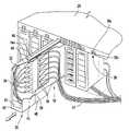
- FIG. 1is a perspective view of a telecommunications patching assembly with a patching module system according to embodiments of the present invention.
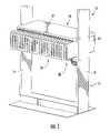
- FIG. 2is a perspective view of a plurality of patching modules of the patching module system of FIG. 1 .
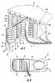
- FIG. 3is an enlarged perspective of the patching modules of FIG. 2 installed in the carrier of the patching module system of FIG. 1 , with one of the patching modules shown in an access position.
- FIG. 4is a side view of an exemplary patching module of the patching module system of FIG. 1 shown with patch cords connected to the connectors of the module.
- FIG. 5is a side view of an exemplary patching module of the assembly of FIG. 1 showing patch cords routed into a trough.
- spatially relative termssuch as “under”, “below”, “lower”, “over”, “upper” and the like, may be used herein for ease of description to describe one element or feature's relationship to another element(s) or feature(s) as illustrated in the figures. It will be understood that the spatially relative terms are intended to encompass different orientations of the device in use or operation in addition to the orientation depicted in the figures. For example, if the device in the figures is turned over, elements described as “under” or “beneath” other elements or features would then be oriented “over” or “above” the other elements or features. Thus, the exemplary term “under” can encompass both an orientation of over and under. The device may be otherwise oriented (rotated 90 degrees or at other orientations) and the spatially relative descriptors used herein interpreted accordingly.
- a connectoris intended to encompass telecommunications connectors and devices employed to facilitate the interconnection of telecommunications cords and cables for the transmission of signals therebetween.
- a connectormay include a termination device at the end of a cord or cable, an adapter that facilitates the interconnection of two termination devices (as may be employed in the interconnection of fiber optic cords and cables, such as may be found in a connector block), a jack, plug, or the like typically employed with copper cables and cords, or other devices that provide a location for the interconnection of cables and cords.
- the rack 10includes a frame 12 having two vertical, spaced apart uprights 14 . Each of the uprights 14 includes mounting holes for the mounting of patching module systems 20 . Although only one patching module system 20 is shown mounted therein, the rack 10 may (and typically will) include multiple patching module systems 20 .
- the patching module system 20includes a module carrier 22 .
- the carrier 22includes a horizontally-disposed main panel 23 and opposing side walls 24 (only one side wall 24 is shown in FIG. 1 ).
- the main panel 23has a plurality of parallel longitudinal slots 28 that extend from the front edge to the rear edge of the carrier 22 .
- Each of the slots 28includes a pair of lips 28 a that cause the slots 28 to have generally a T-shaped profile.
- Those skilled in this artwill recognize that other slot shapes, including triangular, lobed, and the like, may also be employed with the present invention.
- the module carrier 22may be formed of any material that is sufficiently strong and rigid to support items dangling from it.
- the carrier 22may be formed of metal, in particular steel.
- the carrier 22may take a different configuration than that illustrated and described; for example, the carrier 22 may lack side walls in some embodiments. Other configurations will be apparent to those of skill in this art.
- the patching module system 20includes a plurality of patching modules 30 .
- each of the modules 30is identical to the other of the modules 30 ; as such, only one module 30 will be described herein. Those of skill in this art will appreciate that the discussion of the module 30 applies equally to the other modules. Also, in some embodiments one or more of the modules 30 may not be identical to the others.
- each of the modules 30includes a main panel 32 , a front panel 42 , a bottom panel 48 and a top panel 44 .
- a partial panel 45(shown in partial cutaway view in FIG. 3 ) may be included opposite the main panel 32 .
- a longitudinally-extending guide 46 having a T-shaped profile due to the presence of wings 46 ais attached to the top panel 44 (in other embodiments, the profile of the guide 46 may have a different shape to match a differently shaped profile of the slot 28 ).
- a connector mounting block 34is attached to a forward portion of the main panel 32 and houses a plurality of connectors 36 that face forwardly and rearwardly. As can be seen in FIG.
- FIG. 3illustrates that information regarding the interconnections of the module 30 or the like can be included on a label 43 attached to the front panel 42 . It can also be seen in FIG. 3 that the bottom panel 48 includes a cutout area 50 rearward of the connector mounting block 34 .
- the modules 30may be formed of any material suitable for the mounting of connectors 36 .
- Exemplary materialsmay include polymeric materials, including ABS, polycarbonate and the like, or metallic materials.
- the module 30may also be employed.
- the modulemay lack a bottom wall, or the cutout area may be omitted or shaped differently.
- the positions of the fiber guide 38 and the connector mounting block 34may be shifted. Other variations will be apparent to those of skill in this art.
- each module 30can be mounted on the carrier 22 by inserting the guide 46 into a respective slot 28 ; the T-shapes of the slots 28 and guides 46 enable the modules to be suspended from the carrier 22 , with the main panel 32 being generally vertically disposed.
- patch cords 54can be routed through the cutout area 50 and into the connectors 36 of the connector mounting block 34 .
- Additional patch cords 56can be routed from the front of the connecting mounting block 34 to the fiber guide 38 and, from there, out the rear portion of the module 30 .
- the patch cords 54may be routed from the module 30 via a trough 60 that is mounted to the frame 12 ; patch cords 54 may be held in place in the trough 60 with a retaining bar 62 . With this arrangement, all of the cords and cables can be routed away from the front panels 42 of the modules 30 , which provides a neat and organized appearance to the modules 30 and permits labels 43 affixed to the front panels 42 to be easily viewed by a technician positioned in front of the rack 10 .
- any of the modules 30can be slid along a path defined by the slot 28 from a non-access position, in which the front panel 42 of the module 30 is generally aligned with the front panels 42 of the other modules 30 , to an access position, in which the front panel 42 of the module 30 is positioned forward of the front panels 42 of the other modules 30 , thereby providing access to the connectors 36 within the module.
- a techniciancan connect, disconnect, or reconnect one or more of the patch cords 54 , 56 within the module 30 without disturbing connections in any of the other modules 30 .
- the module 30can then be returned to its non-access position in horizontal alignment with the other modules 30 .
- the patching system 20can provide increased port density.
- the system 20is 3 U in height and includes 24 modules 30 arranged in horizontal alignment. With 6 ports per module 30 , the system 20 can provide 48 ports/U.
- the carrier 22may lack side walls, or may have additional walls, flanges and the like to facilitate attachment of the carrier 22 to the frame 12 .
- the carrier 22may be horizontally disposed but inverted, such that the modules 30 reside above the main panel 23 and rest thereon rather than being suspended from the main panel 23 as shown in the illustrated embodiment.
- Other modifications to the carrier that enable this component to provide mounting locations for the modules 30will be apparent to those of skill in this art.
- the modules 30may take other configurations.
- the fiber guides 38may be omitted, may take a different shape, or may be located in a different position on the main panel 32 .
- the connector mounting block 34may be repositioned on the main panel 32 , and/or may include different numbers of connectors. Other variations may also be employed.
Landscapes
- Physics & Mathematics (AREA)
- General Physics & Mathematics (AREA)
- Optics & Photonics (AREA)
- Engineering & Computer Science (AREA)
- Computer Networks & Wireless Communication (AREA)
- Light Guides In General And Applications Therefor (AREA)
- Structure Of Telephone Exchanges (AREA)
Abstract
Description
Claims (8)
Priority Applications (3)
| Application Number | Priority Date | Filing Date | Title |
|---|---|---|---|
| US12/275,480US7729586B2 (en) | 2008-10-07 | 2008-11-21 | Telecommunications patching systems with vertically-oriented patching modules |
| GB0917177AGB2464186B (en) | 2008-10-07 | 2009-10-01 | Telecommunications patching systems with vertically-oriented patching modules |
| CN200910253013.9ACN101718898B (en) | 2008-10-07 | 2009-10-09 | Telecommunications patching system with vertically-oriented patching modules |
Applications Claiming Priority (2)
| Application Number | Priority Date | Filing Date | Title |
|---|---|---|---|
| US24669708A | 2008-10-07 | 2008-10-07 | |
| US12/275,480US7729586B2 (en) | 2008-10-07 | 2008-11-21 | Telecommunications patching systems with vertically-oriented patching modules |
Related Parent Applications (1)
| Application Number | Title | Priority Date | Filing Date |
|---|---|---|---|
| US24669708AContinuation-In-Part | 2008-10-07 | 2008-10-07 |
Publications (2)
| Publication Number | Publication Date |
|---|---|
| US20100086274A1 US20100086274A1 (en) | 2010-04-08 |
| US7729586B2true US7729586B2 (en) | 2010-06-01 |
Family
ID=41393665
Family Applications (1)
| Application Number | Title | Priority Date | Filing Date |
|---|---|---|---|
| US12/275,480Expired - Fee RelatedUS7729586B2 (en) | 2008-10-07 | 2008-11-21 | Telecommunications patching systems with vertically-oriented patching modules |
Country Status (3)
| Country | Link |
|---|---|
| US (1) | US7729586B2 (en) |
| CN (1) | CN101718898B (en) |
| GB (1) | GB2464186B (en) |
Cited By (4)
| Publication number | Priority date | Publication date | Assignee | Title |
|---|---|---|---|---|
| US20130306723A1 (en)* | 2012-02-14 | 2013-11-21 | Tyco Electronics Raychem Bvba | Physical layer management (plm) system for use with an optical distribution frame in which trays can be selectively removed and re-attached |
| US20150362691A1 (en)* | 2014-06-17 | 2015-12-17 | Ortronics, Inc. | Modularly Mountable Cable Management Systems and Associated Methods |
| US9690065B2 (en) | 2014-09-12 | 2017-06-27 | Panduit Corp. | High density fiber enclosure and method |
| US10215944B2 (en) | 2016-06-30 | 2019-02-26 | Panduit Corp. | Modular fiber optic tray |
Families Citing this family (38)
| Publication number | Priority date | Publication date | Assignee | Title |
|---|---|---|---|---|
| US8452148B2 (en) | 2008-08-29 | 2013-05-28 | Corning Cable Systems Llc | Independently translatable modules and fiber optic equipment trays in fiber optic equipment |
| US8184938B2 (en) | 2008-08-29 | 2012-05-22 | Corning Cable Systems Llc | Rear-installable fiber optic modules and equipment |
| US11294136B2 (en) | 2008-08-29 | 2022-04-05 | Corning Optical Communications LLC | High density and bandwidth fiber optic apparatuses and related equipment and methods |
| EP2221932B1 (en) | 2009-02-24 | 2011-11-16 | CCS Technology Inc. | Holding device for a cable or an assembly for use with a cable |
| US8699838B2 (en) | 2009-05-14 | 2014-04-15 | Ccs Technology, Inc. | Fiber optic furcation module |
| US9075216B2 (en) | 2009-05-21 | 2015-07-07 | Corning Cable Systems Llc | Fiber optic housings configured to accommodate fiber optic modules/cassettes and fiber optic panels, and related components and methods |
| US8538226B2 (en) | 2009-05-21 | 2013-09-17 | Corning Cable Systems Llc | Fiber optic equipment guides and rails configured with stopping position(s), and related equipment and methods |
| WO2010148325A1 (en) | 2009-06-19 | 2010-12-23 | Corning Cable Systems Llc | High fiber optic cable packing density apparatus |
| EP2443497B1 (en) | 2009-06-19 | 2020-03-04 | Corning Cable Systems LLC | High density and bandwidth fiber optic apparatus |
| US8712206B2 (en) | 2009-06-19 | 2014-04-29 | Corning Cable Systems Llc | High-density fiber optic modules and module housings and related equipment |
| US8625950B2 (en) | 2009-12-18 | 2014-01-07 | Corning Cable Systems Llc | Rotary locking apparatus for fiber optic equipment trays and related methods |
| US8992099B2 (en) | 2010-02-04 | 2015-03-31 | Corning Cable Systems Llc | Optical interface cards, assemblies, and related methods, suited for installation and use in antenna system equipment |
| US8913866B2 (en) | 2010-03-26 | 2014-12-16 | Corning Cable Systems Llc | Movable adapter panel |
| CA2796221C (en) | 2010-04-16 | 2018-02-13 | Ccs Technology, Inc. | Sealing and strain relief device for data cables |
| EP2381284B1 (en) | 2010-04-23 | 2014-12-31 | CCS Technology Inc. | Under floor fiber optic distribution device |
| US8705926B2 (en) | 2010-04-30 | 2014-04-22 | Corning Optical Communications LLC | Fiber optic housings having a removable top, and related components and methods |
| US9632270B2 (en) | 2010-04-30 | 2017-04-25 | Corning Optical Communications LLC | Fiber optic housings configured for tool-less assembly, and related components and methods |
| US8660397B2 (en) | 2010-04-30 | 2014-02-25 | Corning Cable Systems Llc | Multi-layer module |
| US8879881B2 (en) | 2010-04-30 | 2014-11-04 | Corning Cable Systems Llc | Rotatable routing guide and assembly |
| US9075217B2 (en) | 2010-04-30 | 2015-07-07 | Corning Cable Systems Llc | Apparatuses and related components and methods for expanding capacity of fiber optic housings |
| US9519118B2 (en) | 2010-04-30 | 2016-12-13 | Corning Optical Communications LLC | Removable fiber management sections for fiber optic housings, and related components and methods |
| US9720195B2 (en) | 2010-04-30 | 2017-08-01 | Corning Optical Communications LLC | Apparatuses and related components and methods for attachment and release of fiber optic housings to and from an equipment rack |
| US8718436B2 (en) | 2010-08-30 | 2014-05-06 | Corning Cable Systems Llc | Methods, apparatuses for providing secure fiber optic connections |
| US9279951B2 (en) | 2010-10-27 | 2016-03-08 | Corning Cable Systems Llc | Fiber optic module for limited space applications having a partially sealed module sub-assembly |
| US9116324B2 (en) | 2010-10-29 | 2015-08-25 | Corning Cable Systems Llc | Stacked fiber optic modules and fiber optic equipment configured to support stacked fiber optic modules |
| US8662760B2 (en) | 2010-10-29 | 2014-03-04 | Corning Cable Systems Llc | Fiber optic connector employing optical fiber guide member |
| CA2819235C (en) | 2010-11-30 | 2018-01-16 | Corning Cable Systems Llc | Fiber device holder and strain relief device |
| WO2012106510A2 (en) | 2011-02-02 | 2012-08-09 | Corning Cable Systems Llc | Dense fiber optic connector assemblies and related connectors and cables suitable for establishing optical connections for optical backplanes in equipment racks |
| US9008485B2 (en) | 2011-05-09 | 2015-04-14 | Corning Cable Systems Llc | Attachment mechanisms employed to attach a rear housing section to a fiber optic housing, and related assemblies and methods |
| AU2012275598A1 (en) | 2011-06-30 | 2014-01-16 | Corning Optical Communications LLC | Fiber optic equipment assemblies employing non-U-width-sized housings and related methods |
| US8953924B2 (en) | 2011-09-02 | 2015-02-10 | Corning Cable Systems Llc | Removable strain relief brackets for securing fiber optic cables and/or optical fibers to fiber optic equipment, and related assemblies and methods |
| US9038832B2 (en) | 2011-11-30 | 2015-05-26 | Corning Cable Systems Llc | Adapter panel support assembly |
| US9250409B2 (en) | 2012-07-02 | 2016-02-02 | Corning Cable Systems Llc | Fiber-optic-module trays and drawers for fiber-optic equipment |
| ES2551077T3 (en) | 2012-10-26 | 2015-11-16 | Ccs Technology, Inc. | Fiber optic management unit and fiber optic distribution device |
| US8985862B2 (en) | 2013-02-28 | 2015-03-24 | Corning Cable Systems Llc | High-density multi-fiber adapter housings |
| CN109557627A (en)* | 2019-01-15 | 2019-04-02 | 南京普天天纪楼宇智能有限公司 | A kind of pre-terminated type high-density optical-fiber junction box |
| WO2024107586A2 (en)* | 2022-11-15 | 2024-05-23 | Afl Telecommunications Llc | Telecommunications rack and method for routing |
| EP4619804A1 (en)* | 2022-11-15 | 2025-09-24 | AFL Telecommunications LLC | Telecommunications rack and method for routing |
Citations (15)
| Publication number | Priority date | Publication date | Assignee | Title |
|---|---|---|---|---|
| US5758003A (en)* | 1996-03-15 | 1998-05-26 | Adc Telecommunications, Inc. | High density fiber management |
| US6236795B1 (en)* | 1999-06-07 | 2001-05-22 | E. Walter Rodgers | High-density fiber optic cable distribution frame |
| US6416262B1 (en) | 1998-04-01 | 2002-07-09 | Mitsubishi Heavy Industries, Ltd. | Gear shaping method and device and spiral bevel gear cutter |
| US6424781B1 (en) | 1999-03-01 | 2002-07-23 | Adc Telecommunications, Inc. | Optical fiber distribution frame with pivoting connector panels |
| US6438308B1 (en) | 1998-09-30 | 2002-08-20 | Fitel Usa Corp. | Upgradeable connector module for use in a fiber administration system |
| US6535682B1 (en) | 1999-03-01 | 2003-03-18 | Adc Telecommunications, Inc. | Optical fiber distribution frame with connector modules |
| US6556763B1 (en) | 1999-03-01 | 2003-04-29 | Adc Telecommunications, Inc. | Optical fiber distribution frame with connector modules |
| WO2004010193A1 (en) | 2002-07-22 | 2004-01-29 | Adc Telecommunications, Inc. | Fiber management drawer and patch panel |
| US6738554B2 (en)* | 2001-05-07 | 2004-05-18 | Lucent Technologies Inc. | Double helical-S fiber tray |
| US6903266B1 (en)* | 2004-06-21 | 2005-06-07 | Ralph Luciere | Computer cable organizer |
| US20050220436A1 (en)* | 2003-05-30 | 2005-10-06 | Adc Telecommunications, Inc. | Fiber containment system |
| WO2006012389A1 (en) | 2004-07-22 | 2006-02-02 | Panduit Corp. | Front access punch down patch panel |
| US20060029353A1 (en)* | 2004-08-09 | 2006-02-09 | Bolster Kristofer J | Modules including multiple rows of adapters for high density optical fiber distribution frame |
| US7031588B2 (en)* | 2004-04-27 | 2006-04-18 | Commscope Solutions Properties, Llc | Articulated high density fiber optic splice and termination shelf |
| US20070147764A1 (en)* | 2005-12-23 | 2007-06-28 | Hon Hai Precision Industry Co., Ltd. | Optical module testing apparatus |
- 2008
- 2008-11-21USUS12/275,480patent/US7729586B2/ennot_activeExpired - Fee Related
- 2009
- 2009-10-01GBGB0917177Apatent/GB2464186B/ennot_activeExpired - Fee Related
- 2009-10-09CNCN200910253013.9Apatent/CN101718898B/ennot_activeExpired - Fee Related
Patent Citations (15)
| Publication number | Priority date | Publication date | Assignee | Title |
|---|---|---|---|---|
| US5758003A (en)* | 1996-03-15 | 1998-05-26 | Adc Telecommunications, Inc. | High density fiber management |
| US6416262B1 (en) | 1998-04-01 | 2002-07-09 | Mitsubishi Heavy Industries, Ltd. | Gear shaping method and device and spiral bevel gear cutter |
| US6438308B1 (en) | 1998-09-30 | 2002-08-20 | Fitel Usa Corp. | Upgradeable connector module for use in a fiber administration system |
| US6556763B1 (en) | 1999-03-01 | 2003-04-29 | Adc Telecommunications, Inc. | Optical fiber distribution frame with connector modules |
| US6424781B1 (en) | 1999-03-01 | 2002-07-23 | Adc Telecommunications, Inc. | Optical fiber distribution frame with pivoting connector panels |
| US6535682B1 (en) | 1999-03-01 | 2003-03-18 | Adc Telecommunications, Inc. | Optical fiber distribution frame with connector modules |
| US6236795B1 (en)* | 1999-06-07 | 2001-05-22 | E. Walter Rodgers | High-density fiber optic cable distribution frame |
| US6738554B2 (en)* | 2001-05-07 | 2004-05-18 | Lucent Technologies Inc. | Double helical-S fiber tray |
| WO2004010193A1 (en) | 2002-07-22 | 2004-01-29 | Adc Telecommunications, Inc. | Fiber management drawer and patch panel |
| US20050220436A1 (en)* | 2003-05-30 | 2005-10-06 | Adc Telecommunications, Inc. | Fiber containment system |
| US7031588B2 (en)* | 2004-04-27 | 2006-04-18 | Commscope Solutions Properties, Llc | Articulated high density fiber optic splice and termination shelf |
| US6903266B1 (en)* | 2004-06-21 | 2005-06-07 | Ralph Luciere | Computer cable organizer |
| WO2006012389A1 (en) | 2004-07-22 | 2006-02-02 | Panduit Corp. | Front access punch down patch panel |
| US20060029353A1 (en)* | 2004-08-09 | 2006-02-09 | Bolster Kristofer J | Modules including multiple rows of adapters for high density optical fiber distribution frame |
| US20070147764A1 (en)* | 2005-12-23 | 2007-06-28 | Hon Hai Precision Industry Co., Ltd. | Optical module testing apparatus |
Non-Patent Citations (2)
| Title |
|---|
| ADC Telecommunications, Inc. Brochure: "Room to Grow", one page, Website: www.adc.com/truenet, (2007). |
| Combined Search and Examination Report for UK Intellectual Property Office for GB 0917177.8 dated Nov. 5, 2009. |
Cited By (22)
| Publication number | Priority date | Publication date | Assignee | Title |
|---|---|---|---|---|
| US9361600B2 (en)* | 2012-02-14 | 2016-06-07 | Tyco Electronics Uk Ltd | Physical layer management (PLM) system for use with an optical distribution frame in which trays can be selectively removed and re-attached |
| US20130306723A1 (en)* | 2012-02-14 | 2013-11-21 | Tyco Electronics Raychem Bvba | Physical layer management (plm) system for use with an optical distribution frame in which trays can be selectively removed and re-attached |
| US9805332B2 (en) | 2012-02-14 | 2017-10-31 | Commscope Connectivity Uk Limited | Physical layer management (PLM) system for use with an optical distribution frame having trays with selectable patch side |
| US9846291B2 (en)* | 2014-06-17 | 2017-12-19 | Ortronics, Inc. | Modularly mountable cable management systems and associated methods |
| US20150362691A1 (en)* | 2014-06-17 | 2015-12-17 | Ortronics, Inc. | Modularly Mountable Cable Management Systems and Associated Methods |
| US9632271B2 (en)* | 2014-06-17 | 2017-04-25 | Ortronics, Inc. | Modularly mountable cable management systems and associated methods |
| US20170199346A1 (en)* | 2014-06-17 | 2017-07-13 | Ortronics, Inc. | Modularly Mountable Cable Management Systems and Associated Methods |
| US10268013B2 (en) | 2014-09-12 | 2019-04-23 | Panduit Corp. | High density fiber enclosure and method |
| US11624888B2 (en) | 2014-09-12 | 2023-04-11 | Panduit Corp. | High density fiber enclosure and method |
| US12228782B2 (en) | 2014-09-12 | 2025-02-18 | Panduit Corp. | High density fiber enclosure and method |
| US9690065B2 (en) | 2014-09-12 | 2017-06-27 | Panduit Corp. | High density fiber enclosure and method |
| US10317637B2 (en) | 2014-09-12 | 2019-06-11 | Panduit Corp. | High density fiber enclosure and method |
| US10606013B2 (en) | 2014-09-12 | 2020-03-31 | Panduit Corp. | High density fiber enclosure and method |
| US10698171B2 (en) | 2014-09-12 | 2020-06-30 | Panduit Corp. | High density fiber enclosure and method |
| US9864158B2 (en) | 2014-09-12 | 2018-01-09 | Panduit Corp. | High density fiber enclosure and method |
| US10768385B2 (en) | 2014-09-12 | 2020-09-08 | Panduit Corp. | High density fiber enclosure and method |
| US11105995B2 (en) | 2014-09-12 | 2021-08-31 | Panduit Corp. | High density fiber enclosure and method |
| US10725258B2 (en) | 2016-06-30 | 2020-07-28 | Panduit Corp. | Modular fiber optic tray |
| US11372185B2 (en) | 2016-06-30 | 2022-06-28 | Panduit Corp. | Modular fiber optic tray |
| US11709331B2 (en) | 2016-06-30 | 2023-07-25 | Panduit Corp. | Modular fiber optic tray |
| US12105338B2 (en) | 2016-06-30 | 2024-10-01 | Panduit Corp. | Modular fiber optic tray |
| US10215944B2 (en) | 2016-06-30 | 2019-02-26 | Panduit Corp. | Modular fiber optic tray |
Also Published As
| Publication number | Publication date |
|---|---|
| US20100086274A1 (en) | 2010-04-08 |
| GB2464186B (en) | 2010-08-25 |
| CN101718898A (en) | 2010-06-02 |
| GB0917177D0 (en) | 2009-11-18 |
| CN101718898B (en) | 2014-09-17 |
| GB2464186A (en) | 2010-04-14 |
Similar Documents
| Publication | Publication Date | Title |
|---|---|---|
| US7729586B2 (en) | Telecommunications patching systems with vertically-oriented patching modules | |
| US7672561B1 (en) | Telecommunications patching system with patching modules | |
| US6353696B1 (en) | Panel for managing jumper storage | |
| EP2567279B1 (en) | Fiber optic housings having a removable top | |
| US6866541B2 (en) | Angled patch panel with cable support bar for network cable racks | |
| US8014646B2 (en) | Telecommunications patching systems with high density patching modules | |
| CA2944673C (en) | Adapter panel with lateral sliding adapter arrays | |
| US8556356B2 (en) | Communication shelf having supports for pivotable adapter panels and method of mounting adapter panels therein | |
| US11054600B2 (en) | Fiber optic apparatus for retrofit fiber optic connectivity | |
| AU2011249872A1 (en) | Door fiber management for fiber optic housings, and related components and methods | |
| AU2011249878A1 (en) | Removable fiber management sections for fiber optic housings, and related components and methods | |
| AU2011331987A1 (en) | Methods for attachment and release of fiber optic housings to and from an equipment rack | |
| MXPA06009961A (en) | A high-density multi-port-module patch panel system. | |
| US7876995B2 (en) | Telecommunications patching systems with obliquely-angled patching modules | |
| US8670644B2 (en) | Manifold for managing fiber optic cable and structures and systems therefor | |
| AU2012358470B2 (en) | Overhead cable termination arrangement | |
| US8824851B2 (en) | Communications enclosure having rear mounted bracket and method of securing a cable bundle to a communications enclosure using a rear mounted bracket | |
| AU2015227494A1 (en) | Fiber optic housings having a removable top, and related components and methods | |
| AU2015227448A1 (en) | Apparatuses and related components and methods for expanding capacity of fiber optic housings |
Legal Events
| Date | Code | Title | Description |
|---|---|---|---|
| AS | Assignment | Owner name:BANK OF AMERICA, N.A., AS ADMINISTRATIVE AGENT,CAL Free format text:PATENT SECURITY AGREEMENT SUPPLEMENT;ASSIGNORS:COMMSCOPE OF NORTH CAROLINA;ANDREW LLC;REEL/FRAME:022118/0955 Effective date:20090115 Owner name:BANK OF AMERICA, N.A., AS ADMINISTRATIVE AGENT, CA Free format text:PATENT SECURITY AGREEMENT SUPPLEMENT;ASSIGNORS:COMMSCOPE OF NORTH CAROLINA;ANDREW LLC;REEL/FRAME:022118/0955 Effective date:20090115 | |
| AS | Assignment | Owner name:COMMSCOPE INC. OF NORTH CAROLINA,NORTH CAROLINA Free format text:ASSIGNMENT OF ASSIGNORS INTEREST;ASSIGNOR:KEITH, SCOTT MARTIN;REEL/FRAME:022194/0551 Effective date:20090123 | |
| AS | Assignment | Owner name:COMMSCOPE, INC. OF NORTH CAROLINA, NORTH CAROLINA Free format text:PATENT RELEASE;ASSIGNOR:BANK OF AMERICA, N.A., AS ADMINISTRATIVE AGENT;REEL/FRAME:026039/0005 Effective date:20110114 Owner name:ALLEN TELECOM LLC, NORTH CAROLINA Free format text:PATENT RELEASE;ASSIGNOR:BANK OF AMERICA, N.A., AS ADMINISTRATIVE AGENT;REEL/FRAME:026039/0005 Effective date:20110114 Owner name:ANDREW LLC (F/K/A ANDREW CORPORATION), NORTH CAROL Free format text:PATENT RELEASE;ASSIGNOR:BANK OF AMERICA, N.A., AS ADMINISTRATIVE AGENT;REEL/FRAME:026039/0005 Effective date:20110114 | |
| AS | Assignment | Owner name:JPMORGAN CHASE BANK, N.A., AS COLLATERAL AGENT, NE Free format text:SECURITY AGREEMENT;ASSIGNORS:ALLEN TELECOM LLC, A DELAWARE LLC;ANDREW LLC, A DELAWARE LLC;COMMSCOPE, INC. OF NORTH CAROLINA, A NORTH CAROLINA CORPORATION;REEL/FRAME:026276/0363 Effective date:20110114 | |
| AS | Assignment | Owner name:JPMORGAN CHASE BANK, N.A., AS COLLATERAL AGENT, NE Free format text:SECURITY AGREEMENT;ASSIGNORS:ALLEN TELECOM LLC, A DELAWARE LLC;ANDREW LLC, A DELAWARE LLC;COMMSCOPE, INC OF NORTH CAROLINA, A NORTH CAROLINA CORPORATION;REEL/FRAME:026272/0543 Effective date:20110114 | |
| FPAY | Fee payment | Year of fee payment:4 | |
| AS | Assignment | Owner name:WILMINGTON TRUST, NATIONAL ASSOCIATION, AS COLLATERAL AGENT, CONNECTICUT Free format text:SECURITY INTEREST;ASSIGNORS:ALLEN TELECOM LLC;COMMSCOPE TECHNOLOGIES LLC;COMMSCOPE, INC. OF NORTH CAROLINA;AND OTHERS;REEL/FRAME:036201/0283 Effective date:20150611 Owner name:WILMINGTON TRUST, NATIONAL ASSOCIATION, AS COLLATE Free format text:SECURITY INTEREST;ASSIGNORS:ALLEN TELECOM LLC;COMMSCOPE TECHNOLOGIES LLC;COMMSCOPE, INC. OF NORTH CAROLINA;AND OTHERS;REEL/FRAME:036201/0283 Effective date:20150611 | |
| AS | Assignment | Owner name:COMMSCOPE, INC. OF NORTH CAROLINA, NORTH CAROLINA Free format text:RELEASE OF SECURITY INTEREST PATENTS (RELEASES RF 036201/0283);ASSIGNOR:WILMINGTON TRUST, NATIONAL ASSOCIATION;REEL/FRAME:042126/0434 Effective date:20170317 Owner name:REDWOOD SYSTEMS, INC., NORTH CAROLINA Free format text:RELEASE OF SECURITY INTEREST PATENTS (RELEASES RF 036201/0283);ASSIGNOR:WILMINGTON TRUST, NATIONAL ASSOCIATION;REEL/FRAME:042126/0434 Effective date:20170317 Owner name:COMMSCOPE TECHNOLOGIES LLC, NORTH CAROLINA Free format text:RELEASE OF SECURITY INTEREST PATENTS (RELEASES RF 036201/0283);ASSIGNOR:WILMINGTON TRUST, NATIONAL ASSOCIATION;REEL/FRAME:042126/0434 Effective date:20170317 Owner name:ALLEN TELECOM LLC, NORTH CAROLINA Free format text:RELEASE OF SECURITY INTEREST PATENTS (RELEASES RF 036201/0283);ASSIGNOR:WILMINGTON TRUST, NATIONAL ASSOCIATION;REEL/FRAME:042126/0434 Effective date:20170317 | |
| FEPP | Fee payment procedure | Free format text:MAINTENANCE FEE REMINDER MAILED (ORIGINAL EVENT CODE: REM.) | |
| LAPS | Lapse for failure to pay maintenance fees | Free format text:PATENT EXPIRED FOR FAILURE TO PAY MAINTENANCE FEES (ORIGINAL EVENT CODE: EXP.) | |
| STCH | Information on status: patent discontinuation | Free format text:PATENT EXPIRED DUE TO NONPAYMENT OF MAINTENANCE FEES UNDER 37 CFR 1.362 | |
| FP | Lapsed due to failure to pay maintenance fee | Effective date:20180601 | |
| AS | Assignment | Owner name:ANDREW LLC, NORTH CAROLINA Free format text:RELEASE BY SECURED PARTY;ASSIGNOR:JPMORGAN CHASE BANK, N.A.;REEL/FRAME:048840/0001 Effective date:20190404 Owner name:COMMSCOPE TECHNOLOGIES LLC, NORTH CAROLINA Free format text:RELEASE BY SECURED PARTY;ASSIGNOR:JPMORGAN CHASE BANK, N.A.;REEL/FRAME:048840/0001 Effective date:20190404 Owner name:ALLEN TELECOM LLC, ILLINOIS Free format text:RELEASE BY SECURED PARTY;ASSIGNOR:JPMORGAN CHASE BANK, N.A.;REEL/FRAME:048840/0001 Effective date:20190404 Owner name:COMMSCOPE, INC. OF NORTH CAROLINA, NORTH CAROLINA Free format text:RELEASE BY SECURED PARTY;ASSIGNOR:JPMORGAN CHASE BANK, N.A.;REEL/FRAME:048840/0001 Effective date:20190404 Owner name:REDWOOD SYSTEMS, INC., NORTH CAROLINA Free format text:RELEASE BY SECURED PARTY;ASSIGNOR:JPMORGAN CHASE BANK, N.A.;REEL/FRAME:048840/0001 Effective date:20190404 Owner name:REDWOOD SYSTEMS, INC., NORTH CAROLINA Free format text:RELEASE BY SECURED PARTY;ASSIGNOR:JPMORGAN CHASE BANK, N.A.;REEL/FRAME:049260/0001 Effective date:20190404 Owner name:COMMSCOPE, INC. OF NORTH CAROLINA, NORTH CAROLINA Free format text:RELEASE BY SECURED PARTY;ASSIGNOR:JPMORGAN CHASE BANK, N.A.;REEL/FRAME:049260/0001 Effective date:20190404 Owner name:COMMSCOPE TECHNOLOGIES LLC, NORTH CAROLINA Free format text:RELEASE BY SECURED PARTY;ASSIGNOR:JPMORGAN CHASE BANK, N.A.;REEL/FRAME:049260/0001 Effective date:20190404 Owner name:ANDREW LLC, NORTH CAROLINA Free format text:RELEASE BY SECURED PARTY;ASSIGNOR:JPMORGAN CHASE BANK, N.A.;REEL/FRAME:049260/0001 Effective date:20190404 Owner name:ALLEN TELECOM LLC, ILLINOIS Free format text:RELEASE BY SECURED PARTY;ASSIGNOR:JPMORGAN CHASE BANK, N.A.;REEL/FRAME:049260/0001 Effective date:20190404 |