US7729087B1 - Magnetic recording head with resistive heating element located near the write coil - Google Patents
Magnetic recording head with resistive heating element located near the write coilDownload PDFInfo
- Publication number
- US7729087B1 US7729087B1US12/103,183US10318308AUS7729087B1US 7729087 B1US7729087 B1US 7729087B1US 10318308 AUS10318308 AUS 10318308AUS 7729087 B1US7729087 B1US 7729087B1
- Authority
- US
- United States
- Prior art keywords
- heating element
- layers
- disposed
- layer
- coil
- Prior art date
- Legal status (The legal status is an assumption and is not a legal conclusion. Google has not performed a legal analysis and makes no representation as to the accuracy of the status listed.)
- Expired - Fee Related
Links
- 238000010438heat treatmentMethods0.000titleclaimsabstractdescription93
- 239000000463materialSubstances0.000claimsabstractdescription47
- 239000010409thin filmSubstances0.000claimsabstractdescription40
- 229910001120nichromeInorganic materials0.000claimsdescription8
- VNNRSPGTAMTISX-UHFFFAOYSA-Nchromium nickelChemical compound[Cr].[Ni]VNNRSPGTAMTISX-UHFFFAOYSA-N0.000claimsdescription7
- 239000000758substrateSubstances0.000claimsdescription6
- -1CuMnNiInorganic materials0.000claims2
- 229910003336CuNiInorganic materials0.000claims2
- 239000010410layerSubstances0.000description63
- 238000000034methodMethods0.000description11
- 239000000725suspensionSubstances0.000description8
- 239000000696magnetic materialSubstances0.000description6
- 238000013459approachMethods0.000description5
- PNEYBMLMFCGWSK-UHFFFAOYSA-Naluminium oxideInorganic materials[O-2].[O-2].[O-2].[Al+3].[Al+3]PNEYBMLMFCGWSK-UHFFFAOYSA-N0.000description4
- 230000008646thermal stressEffects0.000description4
- 239000000470constituentSubstances0.000description3
- 230000001276controlling effectEffects0.000description3
- 238000013461designMethods0.000description3
- 230000001939inductive effectEffects0.000description3
- 230000036961partial effectEffects0.000description3
- 229910001030Iron–nickel alloyInorganic materials0.000description2
- 229910045601alloyInorganic materials0.000description2
- 239000000956alloySubstances0.000description2
- 230000000875corresponding effectEffects0.000description2
- 230000007423decreaseEffects0.000description2
- 230000001965increasing effectEffects0.000description2
- 238000004519manufacturing processMethods0.000description2
- 229910052751metalInorganic materials0.000description2
- 239000002184metalSubstances0.000description2
- 230000002829reductive effectEffects0.000description2
- BNGXYYYYKUGPPF-UHFFFAOYSA-M(3-methylphenyl)methyl-triphenylphosphanium;chlorideChemical compound[Cl-].CC1=CC=CC(C[P+](C=2C=CC=CC=2)(C=2C=CC=CC=2)C=2C=CC=CC=2)=C1BNGXYYYYKUGPPF-UHFFFAOYSA-M0.000description1
- PIGFYZPCRLYGLF-UHFFFAOYSA-NAluminum nitrideChemical compound[Al]#NPIGFYZPCRLYGLF-UHFFFAOYSA-N0.000description1
- OKTJSMMVPCPJKN-UHFFFAOYSA-NCarbonChemical compound[C]OKTJSMMVPCPJKN-UHFFFAOYSA-N0.000description1
- 229910003321CoFeInorganic materials0.000description1
- 229910015372FeAlInorganic materials0.000description1
- 229910015140FeNInorganic materials0.000description1
- 229910000896ManganinInorganic materials0.000description1
- 239000000853adhesiveSubstances0.000description1
- 230000001070adhesive effectEffects0.000description1
- WYTGDNHDOZPMIW-RCBQFDQVSA-NalstonineNatural productsC1=CC2=C3C=CC=CC3=NC2=C2N1C[C@H]1[C@H](C)OC=C(C(=O)OC)[C@H]1C2WYTGDNHDOZPMIW-RCBQFDQVSA-N0.000description1
- 230000004075alterationEffects0.000description1
- 229910000808amorphous metal alloyInorganic materials0.000description1
- 238000010420art techniqueMethods0.000description1
- 230000009286beneficial effectEffects0.000description1
- 229910052799carbonInorganic materials0.000description1
- 230000002596correlated effectEffects0.000description1
- 238000013500data storageMethods0.000description1
- 230000003247decreasing effectEffects0.000description1
- 230000002939deleterious effectEffects0.000description1
- 230000000670limiting effectEffects0.000description1
- 238000012986modificationMethods0.000description1
- 230000004048modificationEffects0.000description1
- 238000013021overheatingMethods0.000description1
- 238000002161passivationMethods0.000description1
- 229910000889permalloyInorganic materials0.000description1
- 239000011241protective layerSubstances0.000description1
- 238000000926separation methodMethods0.000description1
- 239000010421standard materialSubstances0.000description1
- 230000002463transducing effectEffects0.000description1
- WFKWXMTUELFFGS-UHFFFAOYSA-NtungstenChemical compound[W]WFKWXMTUELFFGS-UHFFFAOYSA-N0.000description1
- 229910052721tungstenInorganic materials0.000description1
- 239000010937tungstenSubstances0.000description1
Images


Classifications
- G—PHYSICS
- G11—INFORMATION STORAGE
- G11B—INFORMATION STORAGE BASED ON RELATIVE MOVEMENT BETWEEN RECORD CARRIER AND TRANSDUCER
- G11B5/00—Recording by magnetisation or demagnetisation of a record carrier; Reproducing by magnetic means; Record carriers therefor
- G11B5/127—Structure or manufacture of heads, e.g. inductive
- G11B5/31—Structure or manufacture of heads, e.g. inductive using thin films
- G11B5/3109—Details
- G11B5/313—Disposition of layers
- G11B5/3133—Disposition of layers including layers not usually being a part of the electromagnetic transducer structure and providing additional features, e.g. for improving heat radiation, reduction of power dissipation, adaptations for measurement or indication of gap depth or other properties of the structure
- G—PHYSICS
- G11—INFORMATION STORAGE
- G11B—INFORMATION STORAGE BASED ON RELATIVE MOVEMENT BETWEEN RECORD CARRIER AND TRANSDUCER
- G11B5/00—Recording by magnetisation or demagnetisation of a record carrier; Reproducing by magnetic means; Record carriers therefor
- G11B5/48—Disposition or mounting of heads or head supports relative to record carriers ; arrangements of heads, e.g. for scanning the record carrier to increase the relative speed
- G11B5/58—Disposition or mounting of heads or head supports relative to record carriers ; arrangements of heads, e.g. for scanning the record carrier to increase the relative speed with provision for moving the head for the purpose of maintaining alignment of the head relative to the record carrier during transducing operation, e.g. to compensate for surface irregularities of the latter or for track following
- G11B5/60—Fluid-dynamic spacing of heads from record-carriers
- G11B5/6005—Specially adapted for spacing from a rotating disc using a fluid cushion
- G11B5/6011—Control of flying height
- G11B5/6064—Control of flying height using air pressure
- G—PHYSICS
- G11—INFORMATION STORAGE
- G11B—INFORMATION STORAGE BASED ON RELATIVE MOVEMENT BETWEEN RECORD CARRIER AND TRANSDUCER
- G11B5/00—Recording by magnetisation or demagnetisation of a record carrier; Reproducing by magnetic means; Record carriers therefor
- G11B5/48—Disposition or mounting of heads or head supports relative to record carriers ; arrangements of heads, e.g. for scanning the record carrier to increase the relative speed
- G11B5/58—Disposition or mounting of heads or head supports relative to record carriers ; arrangements of heads, e.g. for scanning the record carrier to increase the relative speed with provision for moving the head for the purpose of maintaining alignment of the head relative to the record carrier during transducing operation, e.g. to compensate for surface irregularities of the latter or for track following
- G11B5/60—Fluid-dynamic spacing of heads from record-carriers
- G11B5/6005—Specially adapted for spacing from a rotating disc using a fluid cushion
- G11B5/6011—Control of flying height
- G11B5/607—Control of flying height using thermal means
Definitions
- the present inventionrelates generally to the field of magnetic recording; more specifically, to methods and apparatus for controlled thermal expansion of thin-film read/write transducers used in magnetic recording heads.
- Disc driveshold and rotate the disc while positioning a read/write head over the disc to read data from it or write data to it.
- the headtypically comprises a read/write transducer formed on the trailing surface of a slider.
- ABSair bearing surface
- the headis said to “fly” over the surface of the rotating media, with the ABS being disposed just above the disc surface.
- the thin film of air formed between the ABS and the disc surfaceis known as the air bearing.
- the very small separation distance between the transducer of the flying head and the surface of the diskis referred to as the “flying height.”
- flying headWhen the flying head is suspended above the recording disc in this manner, it can be moved over a desired concentric track of the disc to access data stored on that track.
- the flying height of the headis a critical factor affecting the density of the magnetic data that can be stored on the disc.
- the magnetic recording industryhas strived to increase the data storage density by employing various techniques aimed at decreasing the average flying height of the head over the rotating magnetic media.
- One prior art technique for reducing the flying height of the magnetic headis to incorporate a heating element into the slider to temporarily heat a portion of the head to cause the transducer elements to move closer to the rotating disc, thereby reducing the flying height during periods of reading and writing. This allows the flying height to be low during reading and writing, and to be high at other times to enhance the durability of the head-disk interface.
- the technique of reducing flying height when reading and writingis commonly known as “dynamic flying height” (DFH) actuation.
- DFDHdynamic flying height
- U.S. Pat. No. 6,775,103teaches a slider head having a patterned heating element which selectively heats the edge of the leading slider surface to cause the head to fly closer to the rotating disc.
- 5,991,113discloses a resistive heating element embedded within the slider body just ahead of the transducer. Application of power to the heating element causes the pole tips of the transducer to protrude toward the data recording surface relative to the air bearing surface of the slider, such that the flying height at the location of the transducer is reduced.
- Magnetic recording headsthat include a heater disposed in an overcoat layer for thermally expanding the surrounding layers, thereby adjusting the distance between the transducer device and the hard disc, are disclosed in U.S. Patent Application Publications US 2004/0184192 and US 2004/0130820.
- U.S. Patent Application Publication US 2004/0075940teaches a heating element that is either physically located in the overcoat layer between the write transducer and a passivation layer, or between the read transducer and the slider body.
- U.S. Patent Application Publication US 2003/0099054discloses a thin-film magnetic head having a heater formed at a position opposite to the air-bearing surface with respect to the magnetic head elements.
- Resistive heating elementshave also been used in so-called “thermally assisted” magnetic recording (TAMR), wherein the magnetic material in the media is locally heated to near or above its Curie temperature in order to lower the coercivity of the recording media during writing. At ambient temperature, the coercivity is high enough for thermal stability of the recorded bits.
- TAMRthermal assisted magnetic recording
- Another past approachinvolves controlling the flying height dynamically by applying a voltage between the flying head and the magnetic storage medium.
- the applied voltagecontrols the vertical movement of the head to increase or decrease the flying height by electrostatic forces.
- This techniqueis described in U.S. Pat. No. 6,529,342.
- One major drawback of the electrostatic force approachis the inability to maintain precise control over the flying height.
- Another approachinvolves piezoelectric head-positioning techniques. Such techniques are disclosed in U.S. Pat. Nos. 6,577,466 and 5,943,189.
- a magnetic disk drive that incorporates a piezoelectric element with a resistive heater located between the read transducer and the slider bodyis described in U.S. Patent Application Publication US 2004/0165305.
- a drawback of such piezoelectric techniquesis that they are typically difficult to manufacture without thermally damaging the read transducer.
- U.S. Pat. No. 6,707,646discloses a method and apparatus for dynamically controlling the flying behavior and height of a read/write head by manipulating the spring constant of the suspension.
- the spring constantis changed by locally varying the material temperature of the suspension arm using a small heater deposited on the surface of the suspension arm. This technique suffers from serious reliability and control problems.
- FIG. 1is a partial top view of a disc drive in accordance with an exemplary embodiment of the present invention.
- FIG. 2is a side view of the slider head shown in FIG. 1 .
- FIG. 3is a cross-sectional side view of a thin-film transducer according to several different embodiments of the present invention.
- FIG. 4is a partial perspective side view of a thin-film transducer according to several different embodiments of the present invention.
- FIG. 5is a table showing properties of three different materials that may be utilized as a patterned resistive heating element in accordance with an embodiment of the present invention.
- FIG. 6is a table showing performance data for several different embodiments of the present invention.
- FIG. 7is a table showing performance data for two additional embodiments of the present invention.
- FIG. 8is a table showing performance data for another two embodiments of the present invention.
- FIG. 9is a table showing performance data for two more embodiments of the present invention.
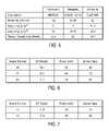
- FIG. 10is a rear side view of a magnetic head in accordance with an embodiment of the present invention.
- FIG. 11is a cross-sectional side view of a thin-film transducer according to several additional embodiments of the present invention.
- FIG. 12Ais a graph that shows protrusion profiles for three different embodiments of the present invention.
- FIG. 12Bis a cross-sectional side view of a thin-film transducer that illustrates various component layers in correlation to the graph of FIG. 12A .
- a magnetic head and disc drive for increased magnetic recording densitiesis described.
- numerous specific detailsare set forth, such as dimensions, material types, configurations, etc., in order to provide a thorough understanding of the present invention.
- persons having ordinary skill in the magnetic recording artswill appreciate that many of these specific details may not be needed to practice the present invention.
- a magnetic disc drive 10including a rotating magnetic disc 11 and a head suspension assembly that supports a magnetic head comprising a slider 14 and a thin-film magnetic transducer 17 disposed on a trailing surface 16 of the slider body for reading/writing of data from/to recording tracks located on magnetic disc 11 .
- the head suspension assemblyincludes a pivotally mounted actuator arm 12 and a suspension arm 13 , which is attached to actuator arm 12 using any one of a number of well-known methods (such as bonding, screw mounting, swaging, etc.).
- Suspension arm 13may be attached to the end of actuator arm 12 in a similar manner.
- Slider 14is typically bonded to the end of suspension arm 13 using an adhesive.
- a resistive heater elementis integrated into the thin-film transducer at one or more specific locations to improve the pole tip protrusion efficiency at low power levels, while reducing or limiting temperature rise in the magnetoresistive (MR) reading element and/or thermal stress in the magnetic head constituent materials.
- Temporary application of power to the resistive heating elementcauses a correspondingly temporary expansion of at least the inductive pole tips such that the flying height of thin-film transducer 17 is temporarily reduced. By lowering the flying height of transducer a higher recording density may be achieved.
- FIG. 3is a cross-sectional side view of a thin-film transducer according to several different embodiments of the present invention.
- FIG. 4is a partial perspective view of a thin-film transducer according to several different embodiments (including those depicted in FIG. 3 ) of the present invention.
- the thin-film transducers illustrated in FIGS. 3 & 4each comprise a layered structure formed on the trailing-side surface of a slider.
- the thin-film transduceris constructed by layering, on top of a substrate 20 , an undercoat 21 consisting of a nonmagnetic material; a lower (S 1 ) magnetic shield layer 11 consisting of a soft magnetic material (e.g., NiFe, FeN, CoFe, etc.); a MR element 23 embedded in a nonmagnetic material layer 33 , the electrical resistance of the MR element changing in response to an external magnetic field; and an upper (S 2 ) magnetic shield layer 24 consisting of a soft magnetic material.
- the thin-film transducermay also include a variety of other layers.
- AlTiCAl 2 O 3 —TiC
- substrate 20alumina (Al 2 O 3 ) may be used as undercoat 21 ; permalloy (NiFe alloy), FeAl alloy, or a Co-base amorphous alloy as the magnetic shield layers 22 & 24 ; and aluminum nitride (AlN), aluminum nitrate (AlNO 3 ), or alumina as the nonmagnetic material layer 33 , which is disposed between layers 22 & 24 and around MR element 23 .
- MR element 23may comprise any one of a number of standard materials widely known in the prior art.
- MR element 23is formed in a rectangular shape or strip with an end surface exposed at ABS 19 .
- Information magnetically recorded in the mediacan be reproduced by detecting changes in the electrical resistance of MR element 23 , which occur in response to the magnetic field from the magnetic recording media.
- the inductive recording or writing portion of the magnetic headmay comprise a layered structure which includes a first magnetic pole layer 26 consisting of a soft magnetic material; a gap layer 27 consisting of a nonmagnetic material 35 (e.g., alumina) that also surrounds the first and second turn layers (C 1 & C 2 ) of a coil 30 ; a second magnetic pole layer 28 ; and a third magnetic pole layer 29 .
- the second and third magnetic pole layers 28 & 29typically comprise a soft magnetic material and are connected together.
- One section of pole layer 26is also connected to a section of pole layer 28 .
- pole layer 26may extend in the same general plane beneath coil 30 (see FIG. 11 ).
- first, second, and third pole layerscomprise the yoke portion of the magnetic head.
- coil 30has a first set of turns 32 disposed nearest the trailing edge of ABS 19 between pole layers 26 & 29 in the yoke portion of the magnetic head.
- a second set of turns 31is disposed outside of the yoke portion farther from the trailing edge of ABS 19 .
- the pole tips of layers 26 , 28 and 29are exposed near ABS 19 .
- a magnetic fieldcan be generated across gap layer 27 by application of current to coil 30 . This magnetic field can be used to invert the magnetic moment of the magnetic material layered on the surface of the magnetic recording media to record information thereon.
- a thick overcoat protective layer(not shown), consisting of a nonmagnetic material, typically covers the entire thin-film transducer.
- a diamond-like carbon (DLC) materialmay also be applied to the magnetic head to protectively cover the pole tips or to enhance tribological performance by covering portions of ABS 19 .
- first pole layer 26 and upper shield layer 24may be formed as a single integral layer, rather than as the two layers separated by a nonmagnetic layer 25 (typically alumina), as shown in FIG. 3 .
- a resistive heating element 40is located between the C 1 & C 2 coil layers of the first set of turns 32 of coil 30 . That is, the C 1 & C 2 layers of coil 30 are respectively disposed in first and second general planes, and a resistive heating element 40 is disposed in a third general plane between the first and second general planes of coil 30 .
- the first set of turns 32is disposed nearest to ABS 19 , with the second set of turns 31 being disposed farthest from ABS 19 .
- the C 1 & C 2 layersare embedded within material 35 , which material electrically insulates heating element 40 from the turns of coil 30 .
- resistive heating element 40is shown having a generally annular shape, e.g., like a horseshoe, with the portion illustrated in FIG. 3 being disposed nearest ABS 19 , and having first and second arms that extend away from ABS 19 .
- a resistive heating element 41has at least a portion of its constituent material located between the C 1 & C 2 coil layers of the second set of turns 31 of coil 30 .
- resistive heating element 41also has the same general annular shape, and is located in the same general plane, as element 40 of the previous embodiment. The primary difference is that element 41 is located farther away from ABS 19 .
- the portion of element 41 shown in FIG. 3can be disposed a distance within a range of 20 ⁇ m to 60 ⁇ m from ABS 19 .
- a resistive heating element 42has the same general shape as heating element 41 and is located within the same distance range from ABS 19 as element 41 of the previous embodiment. The difference between the two embodiments, however, is that resistive heating element 42 is embedded within material 35 between upper shield layer 24 and the C 1 layer of the second set of turns 31 of coil 30 . Alternatively, heating element 42 may be disposed in nonmagnetic layer 25 below the second set of turns 31 of coil 30 . In all other respects, resistive heating element 42 can be the same as element 41 described above.
- a heating element 43comprises an elongated strip of resistive material disposed substantially over the trace of metal that comprises coil connection 50 , as shown in FIG. 4 .
- Coil connection 50extends in a direction approximately parallel to ABS 19 and electrically connects coil 30 with a pair of terminal bond pads 51 of the C 1 layer.
- Coil connection 50is disposed in the same general plane as the C 1 coil layer.
- the elongated resistive heating element stripis located substantially beneath coil connection 50 (denoted as element 44 in FIG. 4 ).
- resistive heating element 43 (or 44 )is located a distance within a range of 40 ⁇ m to 120 ⁇ m from ABS 19 .
- FIG. 10is a rear side view of a thin-film transducer formed on the trailing surface of slider body 14 in accordance with yet another alternative embodiment of the present invention.
- resistive heating element 42is disposed beneath the C 1 & C 2 layers of coil 30 and has an elongated bar shape that is tapered in the middle rather than the annular shape of the previous embodiment.
- Resistive heating elements 40 and 41 discussed above and shown in FIG. 3may also be implemented with an elongated bar shape, or a variety of other shapes.
- terminal bond pads 51 of the C 1 layerare clearly shown in relation to the terminal bond pads 52 of the C 2 layer.
- Metal trace 54electrically connects terminal bond pads 52 with the C 2 layer of coil 30 . Also shown in FIG.
- each of terminal bond pads 48may be wire bonded to electrical circuitry that temporarily generates current flow through heating element 42 to heat the magnetic recording elements in order to dynamically alter the flying height characteristics of the magnetic head.
- each of the embodiments described abovecomprises a thin-film transducer structure having a single heater element.
- each of the embodiments disclosed aboveincludes one of the heater elements 40 , 41 , 42 , 43 , or 44 in the various locations described.
- Still other alternative embodimentsmay include combinations of two or more of these heater elements.
- one alternative embodimentmay comprise heater elements 41 and 42 electrically coupled in series or parallel. Any electrically coupled combination of multiple ones of the heater elements 40 , 41 , 42 , 43 , or 44 described above is therefore considered within the scope of the present invention.
- each of the resistive heater elements 40 , 41 , 42 , 43 , or 44may vary greatly depending on considerations such as resistance value, layout, design parameters, target pole tip protrusion, etc.
- a NiCr materialNi 80 /Cr 20 by atomic weight
- the tables of FIGS. 6 & 8show performance data of various ones of the embodiments described above, i.e., a magnetic head with a thin-film transducer that includes one of heater elements 40 , 41 , 42 , 43 , and 44 as structurally shown in FIGS. 3 & 4 .
- the table dataincludes temperature rise of the MR reading element (DT reader in ° C.), the power of the heater element (mW), and the maximum thermal stress (Mpa) generated to produce a 6 nm pole tip protrusion profile.
- This performance datawas obtained utilizing a NiCr resistive heating element material having a thickness of about 0.1 ⁇ m, a width of approximately 10 ⁇ m, and a resistance of 140 ohms.
- the data of FIGS. 6 & 8thus demonstrates that the present invention achieves an ideal protrusion profile with a relatively small increase in reader temperature, low power, and low thermal stress.
- FIGS. 7 & 9are tables showing the same performance data criteria listed above for embodiments with a thin-film transducer including one of heater elements 41 , 42 , 43 , and 44 made of NiCr and having a thickness of 0.1 ⁇ m, but with a width of about 20 ⁇ m and a resistance of about 60 ohms.
- FIG. 5is a table listing three materials having properties that make them suitable for use as resistive heating elements in a thin-film transducer or magnetic head fabricated in accordance with the present invention. These materials include Nichrome V (Ni 80 /Cr 20 ), Manganin (Cu 86 /Mn 12 /Ni 2 ), and Constanta (Cu 55 /Ni 45 ). Certain relevant properties are listed for each of these resistive heating element materials, including resistivity, temperature coefficient of resistivity (TCR), coefficient of thermal expansion (CTE), and thermal conductivity.
- TCRtemperature coefficient of resistivity
- CTEcoefficient of thermal expansion
- a suitable resistive materialhas one or more of the following properties: a temperature coefficient of resistivity of about (1.5/° C.) ⁇ 10 ⁇ 4 or less; a coefficient of thermal expansion of about (2.0/° C.) ⁇ 10 ⁇ 5 or less; and/or a thermal conductivity of about 10W/mK or greater.
- FIG. 11is a cross-sectional side view that illustrates a thin-film transducer with a heater for dynamic flying height adjustment in accordance with several additional exemplary embodiments of the present invention.
- the layered magnetic head structure shown in FIG. 11is basically the same as that previously depicted in FIG. 3 , except that the first (P 1 ) pole layer 26 now extends in the same general plane over nonmagnetic layer 25 to beneath the second set of turns 31 of coil 30 .
- resistive heating element 45is shown embedded within nonmagnetic layer 25 directly underneath first pole layer 26 , above shield layer 24 , and beneath the second set of turns 31 of coil 30 .
- Resistive heating element 45is electrically insulated from layers 24 & 26 by the nonmagnetic material that forms layer 25 .
- heating element 45is located approximately the same distance away from ABS 19 as element 41 of the previous embodiment (i.e., 20 ⁇ m to 60 ⁇ m from the air-bearing surface).
- resistive heating element 45may have an annular shape, an elongated, tapered bar shape, or a wide variety of other shapes not shown (e.g., serpentine, oblong, lenticular, lattice, etc.).
- a thin-film transducerincludes a resistive heating element 46 disposed underneath first pole layer 26 , above shield layer 24 , and directly beneath the first set of turns 32 of coil 30 . That is, heating element 46 is embedded within the nonmagnetic material of layer 25 directly under the yoke portion (i.e., nearest ABS 19 ) of the inductive recording element and above the reproducing element of the giant magnetoresistive (GMR) magnetic head of the present invention. The edge of resistive heating element 46 closest to ABS 19 is typically located a distance ranging from about 2 ⁇ m to 20 ⁇ m from ABS 19 . In yet another alternative embodiment, heating element 46 is embedded in nonmagnetic material 35 beneath the C 1 layer of the first set of coil turns 32 and above the first pole layer 26 .
- Still further embodimentsmay locate a resistive heating element strip within nonmagnetic layer 25 at distances from ABS 19 not shown in FIG. 11 .
- a resistive heating elementmay be located an intermediate position between elements 45 & 46 as shown in FIG. 11 .
- Still other embodimentsmay locate the resistive heating element in layer 25 at a position closer to or farther from ABS 19 than that shown in FIG. 11 .
- FIG. 11illustrates multiple heater elements
- each of the thin-film transducer embodiments of FIG. 11 described abovecomprises a structure having a single heater element.
- each of the embodiments disclosed in FIG. 11includes one of the heater elements 41 , 45 , or 46 in the various locations described.
- still other embodimentsmay utilize two or more heating elements disposed in different locations, with the multiple heating elements being coupled either in series or in parallel.
- FIG. 12Ais a protrusion profile graph that shows protrusion distances of the recording and reproducing elements of a thin-film transducer according to three different embodiments of the present invention.
- FIG. 12Bis a cross-sectional side view showing constituent layers of a thin-film transducer structure (no heating element shown) according to an embodiment of the present invention.
- the transducer height dimension shown horizontally in FIG. 12Bcorresponds to the graph of FIG. 12A such that variations in protrusion distance (in nm) can be correlated to the locations of the GMR head transducing layers and elements.
- a maximum protrusionoccurs at a location adjacent MR element 23 .
- Lines 61 - 63indicate the protrusion profile response to about 80 mW of power applied to a resistive heating element of a thin-film transducer in accordance with three different embodiments of the present invention.
- Lines 61 and 63are the protrusion profiles produced by the embodiments shown in FIG. 11 with resistive heating element 46 and 45 , respectively.
- Line 62is the protrusion profile response to 80 mW of power applied to a resistive heating element disposed in layer 25 at a distance from ABS 19 halfway between that of elements 45 & 46 in the transducer structure shown in FIG. 11 .
- the heating elementmay comprise an elongated, tapered bar-shaped resistive layer of NiCr approximately 0.2 ⁇ m thick, approximately 8 ⁇ m wide, and having a resistance in a range of about 50-85 ohms.
- the edge of resistive heating element nearest to ABS 19is about 3.5 ⁇ m from ABS 19 .
- the edge of resistive heating element nearest to ABS 19is about 24 ⁇ m from ABS 19 .
- a target pole tip protrusion of 5.0 nmmay be achieved utilizing a 50 ohm heating element 46 in a GMR head structure as described above with about 60 mW of applied power with a consequent reader temperature rise of about 11° C.
- the same 5.0 nm pole tip protrusionmay be achieved utilizing a 50 ohm heating element 45 with about 65 mW of applied power with a consequent reader temperature rise of about 9.4° C.
- Protrusion efficiencyincreases as the resistive heating element is located closer to ABS 19 . In other words, for a specific protrusion distance target, the power supply requirement decreases, as the heating element is located nearer ABS 19 .
Landscapes
- Physics & Mathematics (AREA)
- Electromagnetism (AREA)
- Engineering & Computer Science (AREA)
- Manufacturing & Machinery (AREA)
- Magnetic Heads (AREA)
Abstract
Description
Claims (12)
Priority Applications (1)
| Application Number | Priority Date | Filing Date | Title |
|---|---|---|---|
| US12/103,183US7729087B1 (en) | 2005-01-18 | 2008-04-15 | Magnetic recording head with resistive heating element located near the write coil |
Applications Claiming Priority (2)
| Application Number | Priority Date | Filing Date | Title |
|---|---|---|---|
| US11/039,635US7372665B1 (en) | 2005-01-18 | 2005-01-18 | Magnetic recording head with resistive heating element located near the write coil |
| US12/103,183US7729087B1 (en) | 2005-01-18 | 2008-04-15 | Magnetic recording head with resistive heating element located near the write coil |
Related Parent Applications (1)
| Application Number | Title | Priority Date | Filing Date |
|---|---|---|---|
| US11/039,635DivisionUS7372665B1 (en) | 2005-01-18 | 2005-01-18 | Magnetic recording head with resistive heating element located near the write coil |
Publications (1)
| Publication Number | Publication Date |
|---|---|
| US7729087B1true US7729087B1 (en) | 2010-06-01 |
Family
ID=39361658
Family Applications (2)
| Application Number | Title | Priority Date | Filing Date |
|---|---|---|---|
| US11/039,635Expired - Fee RelatedUS7372665B1 (en) | 2005-01-18 | 2005-01-18 | Magnetic recording head with resistive heating element located near the write coil |
| US12/103,183Expired - Fee RelatedUS7729087B1 (en) | 2005-01-18 | 2008-04-15 | Magnetic recording head with resistive heating element located near the write coil |
Family Applications Before (1)
| Application Number | Title | Priority Date | Filing Date |
|---|---|---|---|
| US11/039,635Expired - Fee RelatedUS7372665B1 (en) | 2005-01-18 | 2005-01-18 | Magnetic recording head with resistive heating element located near the write coil |
Country Status (1)
| Country | Link |
|---|---|
| US (2) | US7372665B1 (en) |
Cited By (139)
| Publication number | Priority date | Publication date | Assignee | Title |
|---|---|---|---|---|
| US20080030905A1 (en)* | 2006-08-01 | 2008-02-07 | Alps Electric Co., Ltd. | Perpendicular magnetic recording head including heating element |
| US20080212234A1 (en)* | 2006-12-13 | 2008-09-04 | Hitachi Global Storage Technologies Netherlands B.V. | Magnetic head slider |
| US20100097721A1 (en)* | 2008-10-17 | 2010-04-22 | Peter Michael Baumgart | System for controlling contact location during tfc touchdown and methods thereof |
| US8523312B2 (en) | 2010-11-08 | 2013-09-03 | Seagate Technology Llc | Detection system using heating element temperature oscillations |
| US8681446B2 (en)* | 2011-12-21 | 2014-03-25 | Seagate Technology Llc | Methods and devices including multiple resistive heating elements |
| US8737009B2 (en) | 2010-11-17 | 2014-05-27 | Seagate Technology Llc | Resistance temperature sensors for head-media and asperity detection |
| US8830628B1 (en) | 2009-02-23 | 2014-09-09 | Western Digital (Fremont), Llc | Method and system for providing a perpendicular magnetic recording head |
| US8879207B1 (en) | 2011-12-20 | 2014-11-04 | Western Digital (Fremont), Llc | Method for providing a side shield for a magnetic recording transducer using an air bridge |
| US8883017B1 (en) | 2013-03-12 | 2014-11-11 | Western Digital (Fremont), Llc | Method and system for providing a read transducer having seamless interfaces |
| US8917581B1 (en) | 2013-12-18 | 2014-12-23 | Western Digital Technologies, Inc. | Self-anneal process for a near field transducer and chimney in a hard disk drive assembly |
| US8923102B1 (en) | 2013-07-16 | 2014-12-30 | Western Digital (Fremont), Llc | Optical grating coupling for interferometric waveguides in heat assisted magnetic recording heads |
| US8947985B1 (en) | 2013-07-16 | 2015-02-03 | Western Digital (Fremont), Llc | Heat assisted magnetic recording transducers having a recessed pole |
| US8953422B1 (en) | 2014-06-10 | 2015-02-10 | Western Digital (Fremont), Llc | Near field transducer using dielectric waveguide core with fine ridge feature |
| US8958272B1 (en) | 2014-06-10 | 2015-02-17 | Western Digital (Fremont), Llc | Interfering near field transducer for energy assisted magnetic recording |
| US8970988B1 (en) | 2013-12-31 | 2015-03-03 | Western Digital (Fremont), Llc | Electric gaps and method for making electric gaps for multiple sensor arrays |
| US8971160B1 (en) | 2013-12-19 | 2015-03-03 | Western Digital (Fremont), Llc | Near field transducer with high refractive index pin for heat assisted magnetic recording |
| US8976635B1 (en) | 2014-06-10 | 2015-03-10 | Western Digital (Fremont), Llc | Near field transducer driven by a transverse electric waveguide for energy assisted magnetic recording |
| US8982508B1 (en) | 2011-10-31 | 2015-03-17 | Western Digital (Fremont), Llc | Method for providing a side shield for a magnetic recording transducer |
| US8980109B1 (en) | 2012-12-11 | 2015-03-17 | Western Digital (Fremont), Llc | Method for providing a magnetic recording transducer using a combined main pole and side shield CMP for a wraparound shield scheme |
| US8988812B1 (en) | 2013-11-27 | 2015-03-24 | Western Digital (Fremont), Llc | Multi-sensor array configuration for a two-dimensional magnetic recording (TDMR) operation |
| US8984740B1 (en) | 2012-11-30 | 2015-03-24 | Western Digital (Fremont), Llc | Process for providing a magnetic recording transducer having a smooth magnetic seed layer |
| US8988825B1 (en) | 2014-02-28 | 2015-03-24 | Western Digital (Fremont, LLC | Method for fabricating a magnetic writer having half-side shields |
| US8993217B1 (en) | 2013-04-04 | 2015-03-31 | Western Digital (Fremont), Llc | Double exposure technique for high resolution disk imaging |
| US8995087B1 (en) | 2006-11-29 | 2015-03-31 | Western Digital (Fremont), Llc | Perpendicular magnetic recording write head having a wrap around shield |
| US8997832B1 (en) | 2010-11-23 | 2015-04-07 | Western Digital (Fremont), Llc | Method of fabricating micrometer scale components |
| US9001628B1 (en) | 2013-12-16 | 2015-04-07 | Western Digital (Fremont), Llc | Assistant waveguides for evaluating main waveguide coupling efficiency and diode laser alignment tolerances for hard disk |
| US9001467B1 (en) | 2014-03-05 | 2015-04-07 | Western Digital (Fremont), Llc | Method for fabricating side shields in a magnetic writer |
| US9007719B1 (en) | 2013-10-23 | 2015-04-14 | Western Digital (Fremont), Llc | Systems and methods for using double mask techniques to achieve very small features |
| US9007725B1 (en) | 2014-10-07 | 2015-04-14 | Western Digital (Fremont), Llc | Sensor with positive coupling between dual ferromagnetic free layer laminates |
| US9007879B1 (en) | 2014-06-10 | 2015-04-14 | Western Digital (Fremont), Llc | Interfering near field transducer having a wide metal bar feature for energy assisted magnetic recording |
| US9013836B1 (en) | 2013-04-02 | 2015-04-21 | Western Digital (Fremont), Llc | Method and system for providing an antiferromagnetically coupled return pole |
| US9042208B1 (en) | 2013-03-11 | 2015-05-26 | Western Digital Technologies, Inc. | Disk drive measuring fly height by applying a bias voltage to an electrically insulated write component of a head |
| US9042052B1 (en) | 2014-06-23 | 2015-05-26 | Western Digital (Fremont), Llc | Magnetic writer having a partially shunted coil |
| US9042051B2 (en) | 2013-08-15 | 2015-05-26 | Western Digital (Fremont), Llc | Gradient write gap for perpendicular magnetic recording writer |
| US9042057B1 (en) | 2013-01-09 | 2015-05-26 | Western Digital (Fremont), Llc | Methods for providing magnetic storage elements with high magneto-resistance using Heusler alloys |
| US9042058B1 (en) | 2013-10-17 | 2015-05-26 | Western Digital Technologies, Inc. | Shield designed for middle shields in a multiple sensor array |
| US9053735B1 (en) | 2014-06-20 | 2015-06-09 | Western Digital (Fremont), Llc | Method for fabricating a magnetic writer using a full-film metal planarization |
| US9064507B1 (en) | 2009-07-31 | 2015-06-23 | Western Digital (Fremont), Llc | Magnetic etch-stop layer for magnetoresistive read heads |
| US9064528B1 (en) | 2013-05-17 | 2015-06-23 | Western Digital Technologies, Inc. | Interferometric waveguide usable in shingled heat assisted magnetic recording in the absence of a near-field transducer |
| US9065043B1 (en) | 2012-06-29 | 2015-06-23 | Western Digital (Fremont), Llc | Tunnel magnetoresistance read head with narrow shield-to-shield spacing |
| US9064527B1 (en) | 2013-04-12 | 2015-06-23 | Western Digital (Fremont), Llc | High order tapered waveguide for use in a heat assisted magnetic recording head |
| US9070381B1 (en) | 2013-04-12 | 2015-06-30 | Western Digital (Fremont), Llc | Magnetic recording read transducer having a laminated free layer |
| US9082423B1 (en) | 2013-12-18 | 2015-07-14 | Western Digital (Fremont), Llc | Magnetic recording write transducer having an improved trailing surface profile |
| US9087527B1 (en) | 2014-10-28 | 2015-07-21 | Western Digital (Fremont), Llc | Apparatus and method for middle shield connection in magnetic recording transducers |
| US9087534B1 (en) | 2011-12-20 | 2015-07-21 | Western Digital (Fremont), Llc | Method and system for providing a read transducer having soft and hard magnetic bias structures |
| US9093639B2 (en) | 2012-02-21 | 2015-07-28 | Western Digital (Fremont), Llc | Methods for manufacturing a magnetoresistive structure utilizing heating and cooling |
| US9099144B1 (en) | 2013-10-11 | 2015-08-04 | Western Digital Technologies, Inc. | Disk drive evaluating laser performance for heat assisted magnetic recording |
| US9104107B1 (en) | 2013-04-03 | 2015-08-11 | Western Digital (Fremont), Llc | DUV photoresist process |
| US9111564B1 (en) | 2013-04-02 | 2015-08-18 | Western Digital (Fremont), Llc | Magnetic recording writer having a main pole with multiple flare angles |
| US9111550B1 (en) | 2014-12-04 | 2015-08-18 | Western Digital (Fremont), Llc | Write transducer having a magnetic buffer layer spaced between a side shield and a write pole by non-magnetic layers |
| US9111558B1 (en) | 2014-03-14 | 2015-08-18 | Western Digital (Fremont), Llc | System and method of diffractive focusing of light in a waveguide |
| US9123358B1 (en) | 2012-06-11 | 2015-09-01 | Western Digital (Fremont), Llc | Conformal high moment side shield seed layer for perpendicular magnetic recording writer |
| US9123362B1 (en) | 2011-03-22 | 2015-09-01 | Western Digital (Fremont), Llc | Methods for assembling an electrically assisted magnetic recording (EAMR) head |
| US9123374B1 (en) | 2015-02-12 | 2015-09-01 | Western Digital (Fremont), Llc | Heat assisted magnetic recording writer having an integrated polarization rotation plate |
| US9123359B1 (en) | 2010-12-22 | 2015-09-01 | Western Digital (Fremont), Llc | Magnetic recording transducer with sputtered antiferromagnetic coupling trilayer between plated ferromagnetic shields and method of fabrication |
| US9135937B1 (en) | 2014-05-09 | 2015-09-15 | Western Digital (Fremont), Llc | Current modulation on laser diode for energy assisted magnetic recording transducer |
| US9135930B1 (en) | 2014-03-06 | 2015-09-15 | Western Digital (Fremont), Llc | Method for fabricating a magnetic write pole using vacuum deposition |
| US9142233B1 (en) | 2014-02-28 | 2015-09-22 | Western Digital (Fremont), Llc | Heat assisted magnetic recording writer having a recessed pole |
| US9147408B1 (en) | 2013-12-19 | 2015-09-29 | Western Digital (Fremont), Llc | Heated AFM layer deposition and cooling process for TMR magnetic recording sensor with high pinning field |
| US9147404B1 (en) | 2015-03-31 | 2015-09-29 | Western Digital (Fremont), Llc | Method and system for providing a read transducer having a dual free layer |
| US9153255B1 (en) | 2014-03-05 | 2015-10-06 | Western Digital (Fremont), Llc | Method for fabricating a magnetic writer having an asymmetric gap and shields |
| US9183854B2 (en) | 2014-02-24 | 2015-11-10 | Western Digital (Fremont), Llc | Method to make interferometric taper waveguide for HAMR light delivery |
| US9190079B1 (en) | 2014-09-22 | 2015-11-17 | Western Digital (Fremont), Llc | Magnetic write pole having engineered radius of curvature and chisel angle profiles |
| US9190085B1 (en) | 2014-03-12 | 2015-11-17 | Western Digital (Fremont), Llc | Waveguide with reflective grating for localized energy intensity |
| US9194692B1 (en) | 2013-12-06 | 2015-11-24 | Western Digital (Fremont), Llc | Systems and methods for using white light interferometry to measure undercut of a bi-layer structure |
| US9202480B2 (en) | 2009-10-14 | 2015-12-01 | Western Digital (Fremont), LLC. | Double patterning hard mask for damascene perpendicular magnetic recording (PMR) writer |
| US9202493B1 (en) | 2014-02-28 | 2015-12-01 | Western Digital (Fremont), Llc | Method of making an ultra-sharp tip mode converter for a HAMR head |
| US9214165B1 (en) | 2014-12-18 | 2015-12-15 | Western Digital (Fremont), Llc | Magnetic writer having a gradient in saturation magnetization of the shields |
| US9214169B1 (en) | 2014-06-20 | 2015-12-15 | Western Digital (Fremont), Llc | Magnetic recording read transducer having a laminated free layer |
| US9213322B1 (en) | 2012-08-16 | 2015-12-15 | Western Digital (Fremont), Llc | Methods for providing run to run process control using a dynamic tuner |
| US9214172B2 (en) | 2013-10-23 | 2015-12-15 | Western Digital (Fremont), Llc | Method of manufacturing a magnetic read head |
| US9230565B1 (en) | 2014-06-24 | 2016-01-05 | Western Digital (Fremont), Llc | Magnetic shield for magnetic recording head |
| US9236560B1 (en) | 2014-12-08 | 2016-01-12 | Western Digital (Fremont), Llc | Spin transfer torque tunneling magnetoresistive device having a laminated free layer with perpendicular magnetic anisotropy |
| US9245545B1 (en) | 2013-04-12 | 2016-01-26 | Wester Digital (Fremont), Llc | Short yoke length coils for magnetic heads in disk drives |
| US9245543B1 (en) | 2010-06-25 | 2016-01-26 | Western Digital (Fremont), Llc | Method for providing an energy assisted magnetic recording head having a laser integrally mounted to the slider |
| US9245562B1 (en) | 2015-03-30 | 2016-01-26 | Western Digital (Fremont), Llc | Magnetic recording writer with a composite main pole |
| US9251813B1 (en) | 2009-04-19 | 2016-02-02 | Western Digital (Fremont), Llc | Method of making a magnetic recording head |
| US9263071B1 (en) | 2015-03-31 | 2016-02-16 | Western Digital (Fremont), Llc | Flat NFT for heat assisted magnetic recording |
| US9263067B1 (en) | 2013-05-29 | 2016-02-16 | Western Digital (Fremont), Llc | Process for making PMR writer with constant side wall angle |
| US9269382B1 (en) | 2012-06-29 | 2016-02-23 | Western Digital (Fremont), Llc | Method and system for providing a read transducer having improved pinning of the pinned layer at higher recording densities |
| US9275657B1 (en) | 2013-08-14 | 2016-03-01 | Western Digital (Fremont), Llc | Process for making PMR writer with non-conformal side gaps |
| US9280990B1 (en) | 2013-12-11 | 2016-03-08 | Western Digital (Fremont), Llc | Method for fabricating a magnetic writer using multiple etches |
| US9287494B1 (en) | 2013-06-28 | 2016-03-15 | Western Digital (Fremont), Llc | Magnetic tunnel junction (MTJ) with a magnesium oxide tunnel barrier |
| US9286919B1 (en) | 2014-12-17 | 2016-03-15 | Western Digital (Fremont), Llc | Magnetic writer having a dual side gap |
| US9305583B1 (en) | 2014-02-18 | 2016-04-05 | Western Digital (Fremont), Llc | Method for fabricating a magnetic writer using multiple etches of damascene materials |
| US9312064B1 (en) | 2015-03-02 | 2016-04-12 | Western Digital (Fremont), Llc | Method to fabricate a magnetic head including ion milling of read gap using dual layer hard mask |
| US9318130B1 (en) | 2013-07-02 | 2016-04-19 | Western Digital (Fremont), Llc | Method to fabricate tunneling magnetic recording heads with extended pinned layer |
| US9336814B1 (en) | 2013-03-12 | 2016-05-10 | Western Digital (Fremont), Llc | Inverse tapered waveguide for use in a heat assisted magnetic recording head |
| US9343087B1 (en) | 2014-12-21 | 2016-05-17 | Western Digital (Fremont), Llc | Method for fabricating a magnetic writer having half shields |
| US9343086B1 (en) | 2013-09-11 | 2016-05-17 | Western Digital (Fremont), Llc | Magnetic recording write transducer having an improved sidewall angle profile |
| US9343098B1 (en) | 2013-08-23 | 2016-05-17 | Western Digital (Fremont), Llc | Method for providing a heat assisted magnetic recording transducer having protective pads |
| US9349392B1 (en) | 2012-05-24 | 2016-05-24 | Western Digital (Fremont), Llc | Methods for improving adhesion on dielectric substrates |
| US9349394B1 (en) | 2013-10-18 | 2016-05-24 | Western Digital (Fremont), Llc | Method for fabricating a magnetic writer having a gradient side gap |
| US9361913B1 (en) | 2013-06-03 | 2016-06-07 | Western Digital (Fremont), Llc | Recording read heads with a multi-layer AFM layer methods and apparatuses |
| US9361914B1 (en) | 2014-06-18 | 2016-06-07 | Western Digital (Fremont), Llc | Magnetic sensor with thin capping layer |
| US9368134B1 (en) | 2010-12-16 | 2016-06-14 | Western Digital (Fremont), Llc | Method and system for providing an antiferromagnetically coupled writer |
| US9384765B1 (en) | 2015-09-24 | 2016-07-05 | Western Digital (Fremont), Llc | Method and system for providing a HAMR writer having improved optical efficiency |
| US9384763B1 (en) | 2015-03-26 | 2016-07-05 | Western Digital (Fremont), Llc | Dual free layer magnetic reader having a rear bias structure including a soft bias layer |
| US9396742B1 (en) | 2012-11-30 | 2016-07-19 | Western Digital (Fremont), Llc | Magnetoresistive sensor for a magnetic storage system read head, and fabrication method thereof |
| US9396743B1 (en) | 2014-02-28 | 2016-07-19 | Western Digital (Fremont), Llc | Systems and methods for controlling soft bias thickness for tunnel magnetoresistance readers |
| US9406331B1 (en) | 2013-06-17 | 2016-08-02 | Western Digital (Fremont), Llc | Method for making ultra-narrow read sensor and read transducer device resulting therefrom |
| US9424866B1 (en) | 2015-09-24 | 2016-08-23 | Western Digital (Fremont), Llc | Heat assisted magnetic recording write apparatus having a dielectric gap |
| US9431047B1 (en) | 2013-05-01 | 2016-08-30 | Western Digital (Fremont), Llc | Method for providing an improved AFM reader shield |
| US9431032B1 (en) | 2013-08-14 | 2016-08-30 | Western Digital (Fremont), Llc | Electrical connection arrangement for a multiple sensor array usable in two-dimensional magnetic recording |
| US9431038B1 (en) | 2015-06-29 | 2016-08-30 | Western Digital (Fremont), Llc | Method for fabricating a magnetic write pole having an improved sidewall angle profile |
| US9431031B1 (en) | 2015-03-24 | 2016-08-30 | Western Digital (Fremont), Llc | System and method for magnetic transducers having multiple sensors and AFC shields |
| US9431039B1 (en) | 2013-05-21 | 2016-08-30 | Western Digital (Fremont), Llc | Multiple sensor array usable in two-dimensional magnetic recording |
| US9437251B1 (en) | 2014-12-22 | 2016-09-06 | Western Digital (Fremont), Llc | Apparatus and method having TDMR reader to reader shunts |
| US9441938B1 (en) | 2013-10-08 | 2016-09-13 | Western Digital (Fremont), Llc | Test structures for measuring near field transducer disc length |
| US9443541B1 (en) | 2015-03-24 | 2016-09-13 | Western Digital (Fremont), Llc | Magnetic writer having a gradient in saturation magnetization of the shields and return pole |
| US9449621B1 (en) | 2015-03-26 | 2016-09-20 | Western Digital (Fremont), Llc | Dual free layer magnetic reader having a rear bias structure having a high aspect ratio |
| US9449625B1 (en) | 2014-12-24 | 2016-09-20 | Western Digital (Fremont), Llc | Heat assisted magnetic recording head having a plurality of diffusion barrier layers |
| US9472216B1 (en) | 2015-09-23 | 2016-10-18 | Western Digital (Fremont), Llc | Differential dual free layer magnetic reader |
| US9484051B1 (en) | 2015-11-09 | 2016-11-01 | The Provost, Fellows, Foundation Scholars and the other members of Board, of the College of the Holy and Undivided Trinity of Queen Elizabeth near Dublin | Method and system for reducing undesirable reflections in a HAMR write apparatus |
| US9508365B1 (en) | 2015-06-24 | 2016-11-29 | Western Digital (Fremont), LLC. | Magnetic reader having a crystal decoupling structure |
| US9508372B1 (en) | 2015-06-03 | 2016-11-29 | Western Digital (Fremont), Llc | Shingle magnetic writer having a low sidewall angle pole |
| US9508363B1 (en) | 2014-06-17 | 2016-11-29 | Western Digital (Fremont), Llc | Method for fabricating a magnetic write pole having a leading edge bevel |
| US9530443B1 (en) | 2015-06-25 | 2016-12-27 | Western Digital (Fremont), Llc | Method for fabricating a magnetic recording device having a high aspect ratio structure |
| US9564150B1 (en) | 2015-11-24 | 2017-02-07 | Western Digital (Fremont), Llc | Magnetic read apparatus having an improved read sensor isolation circuit |
| US9595273B1 (en) | 2015-09-30 | 2017-03-14 | Western Digital (Fremont), Llc | Shingle magnetic writer having nonconformal shields |
| US9646639B2 (en) | 2015-06-26 | 2017-05-09 | Western Digital (Fremont), Llc | Heat assisted magnetic recording writer having integrated polarization rotation waveguides |
| US9666214B1 (en) | 2015-09-23 | 2017-05-30 | Western Digital (Fremont), Llc | Free layer magnetic reader that may have a reduced shield-to-shield spacing |
| US9721595B1 (en) | 2014-12-04 | 2017-08-01 | Western Digital (Fremont), Llc | Method for providing a storage device |
| US9741366B1 (en) | 2014-12-18 | 2017-08-22 | Western Digital (Fremont), Llc | Method for fabricating a magnetic writer having a gradient in saturation magnetization of the shields |
| US9740805B1 (en) | 2015-12-01 | 2017-08-22 | Western Digital (Fremont), Llc | Method and system for detecting hotspots for photolithographically-defined devices |
| US9754611B1 (en) | 2015-11-30 | 2017-09-05 | Western Digital (Fremont), Llc | Magnetic recording write apparatus having a stepped conformal trailing shield |
| US9767831B1 (en) | 2015-12-01 | 2017-09-19 | Western Digital (Fremont), Llc | Magnetic writer having convex trailing surface pole and conformal write gap |
| US9786301B1 (en) | 2014-12-02 | 2017-10-10 | Western Digital (Fremont), Llc | Apparatuses and methods for providing thin shields in a multiple sensor array |
| US9799351B1 (en) | 2015-11-30 | 2017-10-24 | Western Digital (Fremont), Llc | Short yoke length writer having assist coils |
| US9812155B1 (en) | 2015-11-23 | 2017-11-07 | Western Digital (Fremont), Llc | Method and system for fabricating high junction angle read sensors |
| US9842615B1 (en) | 2015-06-26 | 2017-12-12 | Western Digital (Fremont), Llc | Magnetic reader having a nonmagnetic insertion layer for the pinning layer |
| US9858951B1 (en) | 2015-12-01 | 2018-01-02 | Western Digital (Fremont), Llc | Method for providing a multilayer AFM layer in a read sensor |
| US9881638B1 (en) | 2014-12-17 | 2018-01-30 | Western Digital (Fremont), Llc | Method for providing a near-field transducer (NFT) for a heat assisted magnetic recording (HAMR) device |
| US9934811B1 (en) | 2014-03-07 | 2018-04-03 | Western Digital (Fremont), Llc | Methods for controlling stray fields of magnetic features using magneto-elastic anisotropy |
| US9953670B1 (en) | 2015-11-10 | 2018-04-24 | Western Digital (Fremont), Llc | Method and system for providing a HAMR writer including a multi-mode interference device |
| US10037770B1 (en) | 2015-11-12 | 2018-07-31 | Western Digital (Fremont), Llc | Method for providing a magnetic recording write apparatus having a seamless pole |
| US10074387B1 (en) | 2014-12-21 | 2018-09-11 | Western Digital (Fremont), Llc | Method and system for providing a read transducer having symmetric antiferromagnetically coupled shields |
| US10446181B1 (en)* | 2018-02-21 | 2019-10-15 | Seagate Technology Llc | Temperature control in a transducing head |
| US10957347B1 (en)* | 2020-01-10 | 2021-03-23 | International Business Machines Corporation | Thin film heating device in a write gap |
Families Citing this family (22)
| Publication number | Priority date | Publication date | Assignee | Title |
|---|---|---|---|---|
| JP4050152B2 (en)* | 2001-04-05 | 2008-02-20 | 富士通株式会社 | Manufacturing method of head slider |
| US7660080B1 (en) | 2004-04-30 | 2010-02-09 | Western Digital (Fremont), Llc | Read/write head with dynamic flying height control by magnetostriction |
| US7430098B1 (en) | 2005-01-18 | 2008-09-30 | Western Digital (Fremont), Llc | Perpendicular magnetic recording head with dynamic flying height heating element |
| US7372665B1 (en) | 2005-01-18 | 2008-05-13 | Western Digital (Fremont), Llc | Magnetic recording head with resistive heating element located near the write coil |
| US7428124B1 (en) | 2005-01-18 | 2008-09-23 | Western Digital (Fremont), Llc | Magnetic recording head with resistive heating element and thermal barrier layer |
| US20070103812A1 (en)* | 2005-11-09 | 2007-05-10 | Biskeborn Robert G | Magnetic head closure bond using metal adhesion |
| JP2007184023A (en)* | 2006-01-04 | 2007-07-19 | Hitachi Global Storage Technologies Netherlands Bv | Disk drive and control method thereof |
| US7593188B2 (en)* | 2006-03-31 | 2009-09-22 | Hitachi Global Storage Technologies Netherlands, B.V. | Low protrusion compensation air bearing |
| JP2007335062A (en)* | 2006-05-19 | 2007-12-27 | Alps Electric Co Ltd | Thin film magnetic head |
| JP2008027498A (en)* | 2006-07-19 | 2008-02-07 | Hitachi Global Storage Technologies Netherlands Bv | Magnetic head and magnetic disk device |
| JP2009037691A (en)* | 2007-08-01 | 2009-02-19 | Fujitsu Ltd | A magnetic head having a track width expansion mechanism, a magnetic recording / reproducing apparatus, and a control circuit. |
| US7969685B2 (en)* | 2008-08-13 | 2011-06-28 | Sae Magnetics (Hk) Ltd. | ABS design for dynamic flying height (DFH) applications |
| US7995425B2 (en)* | 2009-03-11 | 2011-08-09 | Headway Technologies, Inc. | Power control of TAMR element during read/write transition |
| JP5550594B2 (en)* | 2011-03-30 | 2014-07-16 | 株式会社東芝 | Magnetic head |
| US8634167B2 (en) | 2011-05-27 | 2014-01-21 | HGST Netherlands B.V. | Magnetic head with self compensating dual thermal fly height control |
| US8749920B1 (en) | 2011-12-16 | 2014-06-10 | Western Digital (Fremont), Llc | Magnetic recording head with dynamic fly height heating and having thermally controlled pole tip protrusion to control and protect reader element |
| US8670214B1 (en) | 2011-12-20 | 2014-03-11 | Western Digital (Fremont), Llc | Method and system for providing enhanced thermal expansion for hard disk drives |
| US8553506B2 (en)* | 2011-12-29 | 2013-10-08 | HGST Netherlands B.V. | Preheat feature for thermally assisted recording |
| US8873201B2 (en) | 2012-02-03 | 2014-10-28 | Seagate Technology Llc | Low-recess write pole coil near shield at media-facing surface |
| US8804280B2 (en)* | 2012-02-03 | 2014-08-12 | Seagate Technology Llc | Actively synchronizing magnetic responses of a shield and a write pole |
| US9159349B2 (en) | 2013-08-28 | 2015-10-13 | Seagate Technology Llc | Writer core incorporating thermal sensor having a temperature coefficient of resistance |
| JP2023005369A (en)* | 2021-06-29 | 2023-01-18 | 株式会社東芝 | Magnetic disk device |
Citations (60)
| Publication number | Priority date | Publication date | Assignee | Title |
|---|---|---|---|---|
| US5021906A (en) | 1989-10-31 | 1991-06-04 | International Business Machines Corporation | Programmable air bearing slider including magnetic read/write element |
| JPH03154240A (en) | 1989-11-13 | 1991-07-02 | Matsushita Electric Ind Co Ltd | Magnetic recording and reproducing device |
| JPH0520635A (en) | 1991-07-11 | 1993-01-29 | Fujitsu Ltd | Magnetic head and magnetic disk device |
| JPH05151734A (en) | 1991-11-27 | 1993-06-18 | Hitachi Ltd | Ultra low flying slider for magnetic recording |
| US5712463A (en) | 1995-09-19 | 1998-01-27 | International Business Machines Corporation | Laser apparatus and method for adjusting the gram load static attitude and flying height of a slider in a head suspension assembly |
| US5943189A (en) | 1996-12-05 | 1999-08-24 | Seagate Technology, Inc. | Piezoelectric engageable slider and slider microactuator |
| US5991113A (en) | 1997-04-07 | 1999-11-23 | Seagate Technology, Inc. | Slider with temperature responsive transducer positioning |
| US6111724A (en) | 1998-04-10 | 2000-08-29 | International Business Machines Corporation | Method of making a magnetic write head with plated self-aligned zero throat height defining layer without reflective notching of a second pole tip |
| US6344949B1 (en) | 1999-07-13 | 2002-02-05 | International Business Machines Corporation | Flying height adjustment for air bearing sliders |
| US20020024774A1 (en) | 2000-08-29 | 2002-02-28 | International Business Machines Corporation | Method and apparatus for dynamically controlling the flying behaviour and height of a read/write head in a storage device |
| US6359746B1 (en) | 1994-09-14 | 2002-03-19 | Kabushiki Kaisha Toshiba | Magnetic disk drive |
| US6493183B1 (en) | 2000-06-29 | 2002-12-10 | International Business Machines Corporation | Thermally-assisted magnetic recording system with head having resistive heater in write gap |
| US6501606B2 (en) | 1999-12-02 | 2002-12-31 | Seagate Technology Llc | Fly height control for a read/write head over patterned media |
| US6504676B1 (en) | 1997-05-15 | 2003-01-07 | Read-Rite Corporation | Magnetic head with low stack height and self-aligned pole tips |
| US20030011932A1 (en) | 2001-07-16 | 2003-01-16 | Youping Mei | Controlled air bearing (CAB) for magnetic spacing control |
| US6529342B1 (en) | 1998-02-24 | 2003-03-04 | Seagate Technology, Inc. | Method for controlling flying height of a magnetic head |
| US6570730B1 (en) | 1999-06-09 | 2003-05-27 | Seagate Technology, Llc. | Shear-based transducer for HDD read/write element height control |
| US20030099054A1 (en) | 2001-11-29 | 2003-05-29 | Akifumi Kamijima | Thin-film magnetic head, head gimbal assembly with thin-film magnetic head and magnetic disk apparatus with head gimbal assembly |
| US6577466B2 (en) | 1998-05-19 | 2003-06-10 | Seagate Technology Llc | Head with active fly height control |
| US6597539B1 (en) | 1999-03-31 | 2003-07-22 | Maxtor Corporation | Suspension assembly for supporting a read/write head over a rotating storage disk with dynamically adjustable fly height |
| US20030235014A1 (en)* | 2002-06-21 | 2003-12-25 | Tdk Corporation | Thin-film magnetic head |
| US20040051996A1 (en) | 2002-09-13 | 2004-03-18 | Seagate Technology Llc | Writer core structures having improved thermal dissipation properties |
| US20040075940A1 (en) | 2002-05-30 | 2004-04-22 | Bajorek Christopher H. | Maintaining profile of a head during operation in a drive |
| US20040130820A1 (en) | 2002-12-19 | 2004-07-08 | Tdk Corporation | Flying type thin-film magnetic head |
| US6775103B2 (en) | 2001-04-02 | 2004-08-10 | Hitachi Global Storage Technologies Netherlands B.V. | Slider head having thermally controlled distal end and assembly with a rotating disc |
| US20040165305A1 (en) | 2003-02-24 | 2004-08-26 | Hitachi Global Storage Technologies Japan, Ltd. | Magnetic disk drive |
| US6791793B1 (en) | 2001-09-14 | 2004-09-14 | Western Digital (Fremont), Inc. | Perpendicular recording write head having a recessed magnetic adjunct pole and method of making the same |
| US20040184192A1 (en) | 2003-03-20 | 2004-09-23 | Tdk Corporation | Head slider, head gimbal assembly, and hard disk drive |
| US6813115B2 (en) | 2002-04-18 | 2004-11-02 | Seagate Technology Llc | Perpendicular magnetic recording head with improved write field gradient |
| US20040218302A1 (en) | 2003-04-30 | 2004-11-04 | Stefan Maat | Electrically resistive heating device for data storage sysems |
| US6816339B1 (en) | 2000-01-10 | 2004-11-09 | Seagate Technology Llc | Perpendicular magnetic recording head with longitudinal magnetic field generator to facilitate magnetization switching |
| US6822829B2 (en) | 2001-10-19 | 2004-11-23 | Seagate Technology Llc | Perpendicular magnetic recording head with a multilayered main write pole |
| US20040240109A1 (en) | 2003-05-30 | 2004-12-02 | Hamann Hendrik F. | Magnetic recording head with heating device |
| US6834026B2 (en) | 2001-12-11 | 2004-12-21 | International Business Machines Corporation | Method for thermally-assisted recording on a magnetic recording disk |
| US20050013034A1 (en) | 2003-07-15 | 2005-01-20 | Margulies David T. | Method for magnetic recording on laminated media with improved media signal-to-noise ratio |
| US6847509B2 (en) | 2001-02-01 | 2005-01-25 | Kabushiki Kaisha Toshiba | Magnetoresistive head and perpendicular magnetic recording-reproducing apparatus |
| US20050018347A1 (en) | 2003-07-21 | 2005-01-27 | Hsiao Wen-Chien David | Localized pole tip heating device for magnetic head for hard disk drive |
| US20050024775A1 (en) | 2003-08-01 | 2005-02-03 | Masayuki Kurita | Magnetic head slider and magnet disk apparatus |
| US20050088784A1 (en) | 2003-10-22 | 2005-04-28 | Seagate Technology Llc | Structures for pole-tip actuation |
| US20050117242A1 (en) | 2003-11-28 | 2005-06-02 | Kabushiki Kaisha Toshiba | Perpendicular magnetic head and perpendicular magnetic disk apparatus |
| US6922311B2 (en) | 2002-04-05 | 2005-07-26 | Alps Electric Co., Ltd. | Thin film magnetic head including coil insulated by organic and inorganic insulating materials |
| US6934113B1 (en) | 2004-03-31 | 2005-08-23 | Western Digital (Fremont), Inc. | Method and system for providing dynamic actuation of a write head using a strain element |
| US20050243473A1 (en) | 2004-04-30 | 2005-11-03 | Headway Technologies, Inc. | Magnetostrictive actuator in a magnetic head |
| US6963464B2 (en)* | 2000-10-26 | 2005-11-08 | Hitachi Global Storage Technologies Japan, Ltd. | Magnetic head heating element in a disk drive |
| US20050254171A1 (en)* | 2004-05-14 | 2005-11-17 | Tdk Corporation | Thin-film magnetic head, head gimbal assembly with thin-film magnetic head, magnetic disk drive apparatus with head gimbal assembly, method for designing thin-film magnetic head and manufacturing method of thin-film magnetic head |
| US20060007594A1 (en)* | 2004-07-08 | 2006-01-12 | Tdk Corporation | Thin-film magnetic head with a heater, head gimbal assembly with the thin-film magnetic head and magnetic disk drive apparatus with the head gimbal assembly |
| US6992865B2 (en) | 2003-06-19 | 2006-01-31 | Seagate Technology Llc | Headstack with semi-permanently deformable element for pole-tip recession adjustment |
| US20060034013A1 (en) | 2004-08-10 | 2006-02-16 | Hitachi Global Storage Technologies Netherlands B.V. | High reliability heater for flying height control |
| US20060102956A1 (en) | 2004-11-18 | 2006-05-18 | Seagate Technology Llc | Etch-stop layers for patterning block structures for reducing thermal protrusion |
| US7092195B1 (en) | 2004-05-28 | 2006-08-15 | Western Digital (Fremont), Inc. | Method of using a magnetic write head having an internal heater |
| US7154696B2 (en) | 2004-02-11 | 2006-12-26 | Hitachi Global Storage Technologies Netherlands B.V. | Tunable fly height using magnetomechanical effect in a magnetic head |
| US7199982B2 (en) | 2004-07-30 | 2007-04-03 | Hitachi Global Storage Technologies Netherlands B.V. | Eliminating ESD exposure for read/write head with heating element |
| US7224553B2 (en) | 2003-08-05 | 2007-05-29 | Tdk Corporation | Thin-film magnetic head, head gimbal assembly, and hard disk drive incorporating a heater |
| US7224547B2 (en) | 2003-09-05 | 2007-05-29 | Hitachi Global Storage Technologies Netherlands B.V. | Increasing head-disk interface reliability using controlled heating |
| US7290324B2 (en) | 2003-07-30 | 2007-11-06 | Hitachi Global Storage Technologies Netherlands, B.V. | Method for fabricating a magnetic head including a media heating element |
| US20080030905A1 (en) | 2006-08-01 | 2008-02-07 | Alps Electric Co., Ltd. | Perpendicular magnetic recording head including heating element |
| US7372665B1 (en) | 2005-01-18 | 2008-05-13 | Western Digital (Fremont), Llc | Magnetic recording head with resistive heating element located near the write coil |
| US7428124B1 (en) | 2005-01-18 | 2008-09-23 | Western Digital (Fremont), Llc | Magnetic recording head with resistive heating element and thermal barrier layer |
| US7430098B1 (en) | 2005-01-18 | 2008-09-30 | Western Digital (Fremont), Llc | Perpendicular magnetic recording head with dynamic flying height heating element |
| US7660080B1 (en) | 2004-04-30 | 2010-02-09 | Western Digital (Fremont), Llc | Read/write head with dynamic flying height control by magnetostriction |
- 2005
- 2005-01-18USUS11/039,635patent/US7372665B1/ennot_activeExpired - Fee Related
- 2008
- 2008-04-15USUS12/103,183patent/US7729087B1/ennot_activeExpired - Fee Related
Patent Citations (65)
| Publication number | Priority date | Publication date | Assignee | Title |
|---|---|---|---|---|
| US5021906A (en) | 1989-10-31 | 1991-06-04 | International Business Machines Corporation | Programmable air bearing slider including magnetic read/write element |
| JPH03154240A (en) | 1989-11-13 | 1991-07-02 | Matsushita Electric Ind Co Ltd | Magnetic recording and reproducing device |
| JPH0520635A (en) | 1991-07-11 | 1993-01-29 | Fujitsu Ltd | Magnetic head and magnetic disk device |
| JPH05151734A (en) | 1991-11-27 | 1993-06-18 | Hitachi Ltd | Ultra low flying slider for magnetic recording |
| US6359746B1 (en) | 1994-09-14 | 2002-03-19 | Kabushiki Kaisha Toshiba | Magnetic disk drive |
| US5712463A (en) | 1995-09-19 | 1998-01-27 | International Business Machines Corporation | Laser apparatus and method for adjusting the gram load static attitude and flying height of a slider in a head suspension assembly |
| US5943189A (en) | 1996-12-05 | 1999-08-24 | Seagate Technology, Inc. | Piezoelectric engageable slider and slider microactuator |
| US5991113A (en) | 1997-04-07 | 1999-11-23 | Seagate Technology, Inc. | Slider with temperature responsive transducer positioning |
| US6504676B1 (en) | 1997-05-15 | 2003-01-07 | Read-Rite Corporation | Magnetic head with low stack height and self-aligned pole tips |
| US6529342B1 (en) | 1998-02-24 | 2003-03-04 | Seagate Technology, Inc. | Method for controlling flying height of a magnetic head |
| US6111724A (en) | 1998-04-10 | 2000-08-29 | International Business Machines Corporation | Method of making a magnetic write head with plated self-aligned zero throat height defining layer without reflective notching of a second pole tip |
| US6577466B2 (en) | 1998-05-19 | 2003-06-10 | Seagate Technology Llc | Head with active fly height control |
| US6597539B1 (en) | 1999-03-31 | 2003-07-22 | Maxtor Corporation | Suspension assembly for supporting a read/write head over a rotating storage disk with dynamically adjustable fly height |
| US6570730B1 (en) | 1999-06-09 | 2003-05-27 | Seagate Technology, Llc. | Shear-based transducer for HDD read/write element height control |
| US6344949B1 (en) | 1999-07-13 | 2002-02-05 | International Business Machines Corporation | Flying height adjustment for air bearing sliders |
| US6501606B2 (en) | 1999-12-02 | 2002-12-31 | Seagate Technology Llc | Fly height control for a read/write head over patterned media |
| US6816339B1 (en) | 2000-01-10 | 2004-11-09 | Seagate Technology Llc | Perpendicular magnetic recording head with longitudinal magnetic field generator to facilitate magnetization switching |
| US6493183B1 (en) | 2000-06-29 | 2002-12-10 | International Business Machines Corporation | Thermally-assisted magnetic recording system with head having resistive heater in write gap |
| US6707646B2 (en) | 2000-08-29 | 2004-03-16 | Hitachi Global Storage Technologies Netherlands B.V. | Method and apparatus for dynamically controlling the flying behavior and height of a read/write head in a storage device by manipulating the spring constant of the suspension |
| US20020024774A1 (en) | 2000-08-29 | 2002-02-28 | International Business Machines Corporation | Method and apparatus for dynamically controlling the flying behaviour and height of a read/write head in a storage device |
| US6963464B2 (en)* | 2000-10-26 | 2005-11-08 | Hitachi Global Storage Technologies Japan, Ltd. | Magnetic head heating element in a disk drive |
| US6847509B2 (en) | 2001-02-01 | 2005-01-25 | Kabushiki Kaisha Toshiba | Magnetoresistive head and perpendicular magnetic recording-reproducing apparatus |
| US6775103B2 (en) | 2001-04-02 | 2004-08-10 | Hitachi Global Storage Technologies Netherlands B.V. | Slider head having thermally controlled distal end and assembly with a rotating disc |
| US20030011932A1 (en) | 2001-07-16 | 2003-01-16 | Youping Mei | Controlled air bearing (CAB) for magnetic spacing control |
| US6791793B1 (en) | 2001-09-14 | 2004-09-14 | Western Digital (Fremont), Inc. | Perpendicular recording write head having a recessed magnetic adjunct pole and method of making the same |
| US6822829B2 (en) | 2001-10-19 | 2004-11-23 | Seagate Technology Llc | Perpendicular magnetic recording head with a multilayered main write pole |
| US20030099054A1 (en) | 2001-11-29 | 2003-05-29 | Akifumi Kamijima | Thin-film magnetic head, head gimbal assembly with thin-film magnetic head and magnetic disk apparatus with head gimbal assembly |
| US6834026B2 (en) | 2001-12-11 | 2004-12-21 | International Business Machines Corporation | Method for thermally-assisted recording on a magnetic recording disk |
| US6922311B2 (en) | 2002-04-05 | 2005-07-26 | Alps Electric Co., Ltd. | Thin film magnetic head including coil insulated by organic and inorganic insulating materials |
| US6813115B2 (en) | 2002-04-18 | 2004-11-02 | Seagate Technology Llc | Perpendicular magnetic recording head with improved write field gradient |
| US20040075940A1 (en) | 2002-05-30 | 2004-04-22 | Bajorek Christopher H. | Maintaining profile of a head during operation in a drive |
| US20030235014A1 (en)* | 2002-06-21 | 2003-12-25 | Tdk Corporation | Thin-film magnetic head |
| US6920020B2 (en) | 2002-06-21 | 2005-07-19 | Tdk Corporation | Thin-film merged magnetic head having a heat-generating layer |
| US20040051996A1 (en) | 2002-09-13 | 2004-03-18 | Seagate Technology Llc | Writer core structures having improved thermal dissipation properties |
| US20040130820A1 (en) | 2002-12-19 | 2004-07-08 | Tdk Corporation | Flying type thin-film magnetic head |
| US20040165305A1 (en) | 2003-02-24 | 2004-08-26 | Hitachi Global Storage Technologies Japan, Ltd. | Magnetic disk drive |
| US20040184192A1 (en) | 2003-03-20 | 2004-09-23 | Tdk Corporation | Head slider, head gimbal assembly, and hard disk drive |
| US20040218302A1 (en) | 2003-04-30 | 2004-11-04 | Stefan Maat | Electrically resistive heating device for data storage sysems |
| US20040240109A1 (en) | 2003-05-30 | 2004-12-02 | Hamann Hendrik F. | Magnetic recording head with heating device |
| US7133254B2 (en) | 2003-05-30 | 2006-11-07 | Hitachi Global Storage Technologies Netherlands B.V. | Magnetic recording head with heating device |
| US6992865B2 (en) | 2003-06-19 | 2006-01-31 | Seagate Technology Llc | Headstack with semi-permanently deformable element for pole-tip recession adjustment |
| US20050013034A1 (en) | 2003-07-15 | 2005-01-20 | Margulies David T. | Method for magnetic recording on laminated media with improved media signal-to-noise ratio |
| US20050018347A1 (en) | 2003-07-21 | 2005-01-27 | Hsiao Wen-Chien David | Localized pole tip heating device for magnetic head for hard disk drive |
| US7023660B2 (en) | 2003-07-21 | 2006-04-04 | Hitachi Global Storage Technologies Netherlands B.V. | Localized pole tip heating device for magnetic head for hard disk drive |
| US7290324B2 (en) | 2003-07-30 | 2007-11-06 | Hitachi Global Storage Technologies Netherlands, B.V. | Method for fabricating a magnetic head including a media heating element |
| US20050024775A1 (en) | 2003-08-01 | 2005-02-03 | Masayuki Kurita | Magnetic head slider and magnet disk apparatus |
| US7224553B2 (en) | 2003-08-05 | 2007-05-29 | Tdk Corporation | Thin-film magnetic head, head gimbal assembly, and hard disk drive incorporating a heater |
| US7224547B2 (en) | 2003-09-05 | 2007-05-29 | Hitachi Global Storage Technologies Netherlands B.V. | Increasing head-disk interface reliability using controlled heating |
| US20050088784A1 (en) | 2003-10-22 | 2005-04-28 | Seagate Technology Llc | Structures for pole-tip actuation |
| US20050117242A1 (en) | 2003-11-28 | 2005-06-02 | Kabushiki Kaisha Toshiba | Perpendicular magnetic head and perpendicular magnetic disk apparatus |
| US7154696B2 (en) | 2004-02-11 | 2006-12-26 | Hitachi Global Storage Technologies Netherlands B.V. | Tunable fly height using magnetomechanical effect in a magnetic head |
| US6934113B1 (en) | 2004-03-31 | 2005-08-23 | Western Digital (Fremont), Inc. | Method and system for providing dynamic actuation of a write head using a strain element |
| US7660080B1 (en) | 2004-04-30 | 2010-02-09 | Western Digital (Fremont), Llc | Read/write head with dynamic flying height control by magnetostriction |
| US20050243473A1 (en) | 2004-04-30 | 2005-11-03 | Headway Technologies, Inc. | Magnetostrictive actuator in a magnetic head |
| US20050254171A1 (en)* | 2004-05-14 | 2005-11-17 | Tdk Corporation | Thin-film magnetic head, head gimbal assembly with thin-film magnetic head, magnetic disk drive apparatus with head gimbal assembly, method for designing thin-film magnetic head and manufacturing method of thin-film magnetic head |
| US7092195B1 (en) | 2004-05-28 | 2006-08-15 | Western Digital (Fremont), Inc. | Method of using a magnetic write head having an internal heater |
| US7283327B1 (en) | 2004-05-28 | 2007-10-16 | Western Digital (Fremont), Llc | Magnetic write head having resistive heater coil |
| US20060007594A1 (en)* | 2004-07-08 | 2006-01-12 | Tdk Corporation | Thin-film magnetic head with a heater, head gimbal assembly with the thin-film magnetic head and magnetic disk drive apparatus with the head gimbal assembly |
| US7199982B2 (en) | 2004-07-30 | 2007-04-03 | Hitachi Global Storage Technologies Netherlands B.V. | Eliminating ESD exposure for read/write head with heating element |
| US20060034013A1 (en) | 2004-08-10 | 2006-02-16 | Hitachi Global Storage Technologies Netherlands B.V. | High reliability heater for flying height control |
| US20060102956A1 (en) | 2004-11-18 | 2006-05-18 | Seagate Technology Llc | Etch-stop layers for patterning block structures for reducing thermal protrusion |
| US7372665B1 (en) | 2005-01-18 | 2008-05-13 | Western Digital (Fremont), Llc | Magnetic recording head with resistive heating element located near the write coil |
| US7428124B1 (en) | 2005-01-18 | 2008-09-23 | Western Digital (Fremont), Llc | Magnetic recording head with resistive heating element and thermal barrier layer |
| US7430098B1 (en) | 2005-01-18 | 2008-09-30 | Western Digital (Fremont), Llc | Perpendicular magnetic recording head with dynamic flying height heating element |
| US20080030905A1 (en) | 2006-08-01 | 2008-02-07 | Alps Electric Co., Ltd. | Perpendicular magnetic recording head including heating element |
Non-Patent Citations (5)
| Title |
|---|
| Gordon J. Smith, "Dynamic In-Situ Measurements of Head-to-Disk Spacing", IEEE Transactions on Magnetics, vol. 35, No. 5, Sep. 1999, pp. 2346-2351. |
| Institute of Electrical and Electronic Engineers, Inc., The IEEE Standard Dictionary of Electrical and Electronics Terms, sixth edition, IEEE Std. 100-1996, p. 171. |
| Machtle, P., et al., "Integrated Microheaters for In-Situ Flying Height Control of Sliders Used in Hard-Disk Drives", The 14th IEEE International Conference on Micro Electro Mechanical Systems, Meeting Date: Jan. 21-25, 2001, MEMS 2001, pp. 196-199. |
| R.M. Costescu, et al., "Ultra-Low Thermal Conductivity in W/AI2O3 Nanolaminates", Science, vol. 303, Issue 5660, pp. 989-990, Feb. 13, 2004. |
| Vladimir Nikitin, et al., "Spatial and Temporal Profiling of Protrusion in Magnetic Recording Heads", IEEE Transactions on Magnetics, vol. 40, No. 1, Jan. 2004, pp. 326-331. |
Cited By (173)
| Publication number | Priority date | Publication date | Assignee | Title |
|---|---|---|---|---|
| US7898767B2 (en)* | 2006-08-01 | 2011-03-01 | Tdk Corporation | Perpendicular magnetic recording head including heating element |
| US20080030905A1 (en)* | 2006-08-01 | 2008-02-07 | Alps Electric Co., Ltd. | Perpendicular magnetic recording head including heating element |
| US8995087B1 (en) | 2006-11-29 | 2015-03-31 | Western Digital (Fremont), Llc | Perpendicular magnetic recording write head having a wrap around shield |
| US20080212234A1 (en)* | 2006-12-13 | 2008-09-04 | Hitachi Global Storage Technologies Netherlands B.V. | Magnetic head slider |
| US8284521B2 (en)* | 2006-12-13 | 2012-10-09 | Hitachi Global Storage Technologies Netherlands B.V. | Magnetic head slider |
| US20100097721A1 (en)* | 2008-10-17 | 2010-04-22 | Peter Michael Baumgart | System for controlling contact location during tfc touchdown and methods thereof |
| US8149541B2 (en)* | 2008-10-17 | 2012-04-03 | Hitachi Global Storage Technologies Netherlands B.V. | System for controlling contact location during TFC touchdown and methods thereof |
| US8830628B1 (en) | 2009-02-23 | 2014-09-09 | Western Digital (Fremont), Llc | Method and system for providing a perpendicular magnetic recording head |
| US9251813B1 (en) | 2009-04-19 | 2016-02-02 | Western Digital (Fremont), Llc | Method of making a magnetic recording head |
| US9064507B1 (en) | 2009-07-31 | 2015-06-23 | Western Digital (Fremont), Llc | Magnetic etch-stop layer for magnetoresistive read heads |
| US9202480B2 (en) | 2009-10-14 | 2015-12-01 | Western Digital (Fremont), LLC. | Double patterning hard mask for damascene perpendicular magnetic recording (PMR) writer |
| US9245543B1 (en) | 2010-06-25 | 2016-01-26 | Western Digital (Fremont), Llc | Method for providing an energy assisted magnetic recording head having a laser integrally mounted to the slider |
| US9607659B2 (en) | 2010-11-08 | 2017-03-28 | Seagate Technology Llc | Detection system using heating element temperature oscillations |
| US8523312B2 (en) | 2010-11-08 | 2013-09-03 | Seagate Technology Llc | Detection system using heating element temperature oscillations |
| US9449629B2 (en) | 2010-11-17 | 2016-09-20 | Seagate Technology Llc | Resistive temperature sensors for improved asperity, head-media spacing, and/or head-media contact detection |
| US8810952B2 (en) | 2010-11-17 | 2014-08-19 | Seagate Technology Llc | Head transducer with multiple resistance temperature sensors for head-medium spacing and contact detection |
| US9036290B2 (en) | 2010-11-17 | 2015-05-19 | Seagate Technology Llc | Head transducer with multiple resistance temperature sensors for head-medium spacing and contact detection |
| US9111572B2 (en) | 2010-11-17 | 2015-08-18 | Seagate Technology Llc | Asperity and head-media contact detection using multi-stage temperature coefficient of resistance sensor |
| US9230594B2 (en) | 2010-11-17 | 2016-01-05 | Seagate Technology Llc | Resistance temperature sensors for head-media and asperity detection |
| US8737009B2 (en) | 2010-11-17 | 2014-05-27 | Seagate Technology Llc | Resistance temperature sensors for head-media and asperity detection |
| US9123381B2 (en) | 2010-11-17 | 2015-09-01 | Seagate Technology Llc | Resistive temperature sensors for improved asperity, head-media spacing, and/or head-media contact detection |
| US9390741B2 (en) | 2010-11-17 | 2016-07-12 | Saegate Technology Llc | Head transducer with multiple resistance temperature sensors for head-medium spacing and contact detection |
| US9042050B2 (en) | 2010-11-17 | 2015-05-26 | Seagate Technology Llc | Head transducer with multiple resistance temperature sensors for head-medium spacing and contact detection |
| US8760811B2 (en) | 2010-11-17 | 2014-06-24 | Seagate Technology Llc | Asperity and head-media contact detection using multi-stage temperature coefficient of resistance sensor |
| US9373361B2 (en) | 2010-11-17 | 2016-06-21 | Seagate Technology Llc | Asperity and head-media contact detection using multi-stage temperature coefficient of resistance sensor |
| US9812161B2 (en) | 2010-11-17 | 2017-11-07 | Seagate Technology Llc | Resistive temperature sensors for improved asperity, head-media spacing, and/or head-media contact detection |
| US9159345B1 (en) | 2010-11-23 | 2015-10-13 | Western Digital (Fremont), Llc | Micrometer scale components |
| US8997832B1 (en) | 2010-11-23 | 2015-04-07 | Western Digital (Fremont), Llc | Method of fabricating micrometer scale components |
| US9672847B2 (en) | 2010-11-23 | 2017-06-06 | Western Digital (Fremont), Llc | Micrometer scale components |
| US9368134B1 (en) | 2010-12-16 | 2016-06-14 | Western Digital (Fremont), Llc | Method and system for providing an antiferromagnetically coupled writer |
| US9123359B1 (en) | 2010-12-22 | 2015-09-01 | Western Digital (Fremont), Llc | Magnetic recording transducer with sputtered antiferromagnetic coupling trilayer between plated ferromagnetic shields and method of fabrication |
| US9123362B1 (en) | 2011-03-22 | 2015-09-01 | Western Digital (Fremont), Llc | Methods for assembling an electrically assisted magnetic recording (EAMR) head |
| US8982508B1 (en) | 2011-10-31 | 2015-03-17 | Western Digital (Fremont), Llc | Method for providing a side shield for a magnetic recording transducer |
| US8879207B1 (en) | 2011-12-20 | 2014-11-04 | Western Digital (Fremont), Llc | Method for providing a side shield for a magnetic recording transducer using an air bridge |
| US9087534B1 (en) | 2011-12-20 | 2015-07-21 | Western Digital (Fremont), Llc | Method and system for providing a read transducer having soft and hard magnetic bias structures |
| US8681446B2 (en)* | 2011-12-21 | 2014-03-25 | Seagate Technology Llc | Methods and devices including multiple resistive heating elements |
| US9093639B2 (en) | 2012-02-21 | 2015-07-28 | Western Digital (Fremont), Llc | Methods for manufacturing a magnetoresistive structure utilizing heating and cooling |
| US9940950B2 (en) | 2012-05-24 | 2018-04-10 | Western Digital (Fremont), Llc | Methods for improving adhesion on dielectric substrates |
| US9349392B1 (en) | 2012-05-24 | 2016-05-24 | Western Digital (Fremont), Llc | Methods for improving adhesion on dielectric substrates |
| US9123358B1 (en) | 2012-06-11 | 2015-09-01 | Western Digital (Fremont), Llc | Conformal high moment side shield seed layer for perpendicular magnetic recording writer |
| US9269382B1 (en) | 2012-06-29 | 2016-02-23 | Western Digital (Fremont), Llc | Method and system for providing a read transducer having improved pinning of the pinned layer at higher recording densities |
| US9412400B2 (en) | 2012-06-29 | 2016-08-09 | Western Digital (Fremont), Llc | Tunnel magnetoresistance read head with narrow shield-to-shield spacing |
| US9065043B1 (en) | 2012-06-29 | 2015-06-23 | Western Digital (Fremont), Llc | Tunnel magnetoresistance read head with narrow shield-to-shield spacing |
| US9213322B1 (en) | 2012-08-16 | 2015-12-15 | Western Digital (Fremont), Llc | Methods for providing run to run process control using a dynamic tuner |
| US8984740B1 (en) | 2012-11-30 | 2015-03-24 | Western Digital (Fremont), Llc | Process for providing a magnetic recording transducer having a smooth magnetic seed layer |
| US9396742B1 (en) | 2012-11-30 | 2016-07-19 | Western Digital (Fremont), Llc | Magnetoresistive sensor for a magnetic storage system read head, and fabrication method thereof |
| US8980109B1 (en) | 2012-12-11 | 2015-03-17 | Western Digital (Fremont), Llc | Method for providing a magnetic recording transducer using a combined main pole and side shield CMP for a wraparound shield scheme |
| US9042057B1 (en) | 2013-01-09 | 2015-05-26 | Western Digital (Fremont), Llc | Methods for providing magnetic storage elements with high magneto-resistance using Heusler alloys |
| US9042208B1 (en) | 2013-03-11 | 2015-05-26 | Western Digital Technologies, Inc. | Disk drive measuring fly height by applying a bias voltage to an electrically insulated write component of a head |
| US9336814B1 (en) | 2013-03-12 | 2016-05-10 | Western Digital (Fremont), Llc | Inverse tapered waveguide for use in a heat assisted magnetic recording head |
| US8883017B1 (en) | 2013-03-12 | 2014-11-11 | Western Digital (Fremont), Llc | Method and system for providing a read transducer having seamless interfaces |
| US9013836B1 (en) | 2013-04-02 | 2015-04-21 | Western Digital (Fremont), Llc | Method and system for providing an antiferromagnetically coupled return pole |
| US9111564B1 (en) | 2013-04-02 | 2015-08-18 | Western Digital (Fremont), Llc | Magnetic recording writer having a main pole with multiple flare angles |
| US9104107B1 (en) | 2013-04-03 | 2015-08-11 | Western Digital (Fremont), Llc | DUV photoresist process |
| US8993217B1 (en) | 2013-04-04 | 2015-03-31 | Western Digital (Fremont), Llc | Double exposure technique for high resolution disk imaging |
| US9245545B1 (en) | 2013-04-12 | 2016-01-26 | Wester Digital (Fremont), Llc | Short yoke length coils for magnetic heads in disk drives |
| US9064527B1 (en) | 2013-04-12 | 2015-06-23 | Western Digital (Fremont), Llc | High order tapered waveguide for use in a heat assisted magnetic recording head |
| US9070381B1 (en) | 2013-04-12 | 2015-06-30 | Western Digital (Fremont), Llc | Magnetic recording read transducer having a laminated free layer |
| US9431047B1 (en) | 2013-05-01 | 2016-08-30 | Western Digital (Fremont), Llc | Method for providing an improved AFM reader shield |
| US9064528B1 (en) | 2013-05-17 | 2015-06-23 | Western Digital Technologies, Inc. | Interferometric waveguide usable in shingled heat assisted magnetic recording in the absence of a near-field transducer |
| US9431039B1 (en) | 2013-05-21 | 2016-08-30 | Western Digital (Fremont), Llc | Multiple sensor array usable in two-dimensional magnetic recording |
| US9263067B1 (en) | 2013-05-29 | 2016-02-16 | Western Digital (Fremont), Llc | Process for making PMR writer with constant side wall angle |
| US9361913B1 (en) | 2013-06-03 | 2016-06-07 | Western Digital (Fremont), Llc | Recording read heads with a multi-layer AFM layer methods and apparatuses |
| US9406331B1 (en) | 2013-06-17 | 2016-08-02 | Western Digital (Fremont), Llc | Method for making ultra-narrow read sensor and read transducer device resulting therefrom |
| US9287494B1 (en) | 2013-06-28 | 2016-03-15 | Western Digital (Fremont), Llc | Magnetic tunnel junction (MTJ) with a magnesium oxide tunnel barrier |
| US9318130B1 (en) | 2013-07-02 | 2016-04-19 | Western Digital (Fremont), Llc | Method to fabricate tunneling magnetic recording heads with extended pinned layer |
| US8923102B1 (en) | 2013-07-16 | 2014-12-30 | Western Digital (Fremont), Llc | Optical grating coupling for interferometric waveguides in heat assisted magnetic recording heads |
| US8947985B1 (en) | 2013-07-16 | 2015-02-03 | Western Digital (Fremont), Llc | Heat assisted magnetic recording transducers having a recessed pole |
| US9275657B1 (en) | 2013-08-14 | 2016-03-01 | Western Digital (Fremont), Llc | Process for making PMR writer with non-conformal side gaps |
| US9431032B1 (en) | 2013-08-14 | 2016-08-30 | Western Digital (Fremont), Llc | Electrical connection arrangement for a multiple sensor array usable in two-dimensional magnetic recording |
| US9042051B2 (en) | 2013-08-15 | 2015-05-26 | Western Digital (Fremont), Llc | Gradient write gap for perpendicular magnetic recording writer |
| US9343098B1 (en) | 2013-08-23 | 2016-05-17 | Western Digital (Fremont), Llc | Method for providing a heat assisted magnetic recording transducer having protective pads |
| US9343086B1 (en) | 2013-09-11 | 2016-05-17 | Western Digital (Fremont), Llc | Magnetic recording write transducer having an improved sidewall angle profile |
| US9441938B1 (en) | 2013-10-08 | 2016-09-13 | Western Digital (Fremont), Llc | Test structures for measuring near field transducer disc length |
| US9099144B1 (en) | 2013-10-11 | 2015-08-04 | Western Digital Technologies, Inc. | Disk drive evaluating laser performance for heat assisted magnetic recording |
| US9042058B1 (en) | 2013-10-17 | 2015-05-26 | Western Digital Technologies, Inc. | Shield designed for middle shields in a multiple sensor array |
| US9349394B1 (en) | 2013-10-18 | 2016-05-24 | Western Digital (Fremont), Llc | Method for fabricating a magnetic writer having a gradient side gap |
| US9007719B1 (en) | 2013-10-23 | 2015-04-14 | Western Digital (Fremont), Llc | Systems and methods for using double mask techniques to achieve very small features |
| US9214172B2 (en) | 2013-10-23 | 2015-12-15 | Western Digital (Fremont), Llc | Method of manufacturing a magnetic read head |
| US9830936B2 (en) | 2013-10-23 | 2017-11-28 | Western Digital (Fremont), Llc | Magnetic read head with antiferromagentic layer |
| US8988812B1 (en) | 2013-11-27 | 2015-03-24 | Western Digital (Fremont), Llc | Multi-sensor array configuration for a two-dimensional magnetic recording (TDMR) operation |
| US9194692B1 (en) | 2013-12-06 | 2015-11-24 | Western Digital (Fremont), Llc | Systems and methods for using white light interferometry to measure undercut of a bi-layer structure |
| US9280990B1 (en) | 2013-12-11 | 2016-03-08 | Western Digital (Fremont), Llc | Method for fabricating a magnetic writer using multiple etches |
| US9001628B1 (en) | 2013-12-16 | 2015-04-07 | Western Digital (Fremont), Llc | Assistant waveguides for evaluating main waveguide coupling efficiency and diode laser alignment tolerances for hard disk |
| US9082423B1 (en) | 2013-12-18 | 2015-07-14 | Western Digital (Fremont), Llc | Magnetic recording write transducer having an improved trailing surface profile |
| US8917581B1 (en) | 2013-12-18 | 2014-12-23 | Western Digital Technologies, Inc. | Self-anneal process for a near field transducer and chimney in a hard disk drive assembly |
| US8971160B1 (en) | 2013-12-19 | 2015-03-03 | Western Digital (Fremont), Llc | Near field transducer with high refractive index pin for heat assisted magnetic recording |
| US9147408B1 (en) | 2013-12-19 | 2015-09-29 | Western Digital (Fremont), Llc | Heated AFM layer deposition and cooling process for TMR magnetic recording sensor with high pinning field |
| US8970988B1 (en) | 2013-12-31 | 2015-03-03 | Western Digital (Fremont), Llc | Electric gaps and method for making electric gaps for multiple sensor arrays |
| US9305583B1 (en) | 2014-02-18 | 2016-04-05 | Western Digital (Fremont), Llc | Method for fabricating a magnetic writer using multiple etches of damascene materials |
| US9183854B2 (en) | 2014-02-24 | 2015-11-10 | Western Digital (Fremont), Llc | Method to make interferometric taper waveguide for HAMR light delivery |
| US9202493B1 (en) | 2014-02-28 | 2015-12-01 | Western Digital (Fremont), Llc | Method of making an ultra-sharp tip mode converter for a HAMR head |
| US9142233B1 (en) | 2014-02-28 | 2015-09-22 | Western Digital (Fremont), Llc | Heat assisted magnetic recording writer having a recessed pole |
| US8988825B1 (en) | 2014-02-28 | 2015-03-24 | Western Digital (Fremont, LLC | Method for fabricating a magnetic writer having half-side shields |
| US9396743B1 (en) | 2014-02-28 | 2016-07-19 | Western Digital (Fremont), Llc | Systems and methods for controlling soft bias thickness for tunnel magnetoresistance readers |
| US9153255B1 (en) | 2014-03-05 | 2015-10-06 | Western Digital (Fremont), Llc | Method for fabricating a magnetic writer having an asymmetric gap and shields |
| US9349393B2 (en) | 2014-03-05 | 2016-05-24 | Western Digital (Fremont), Llc | Magnetic writer having an asymmetric gap and shields |
| US9001467B1 (en) | 2014-03-05 | 2015-04-07 | Western Digital (Fremont), Llc | Method for fabricating side shields in a magnetic writer |
| US9135930B1 (en) | 2014-03-06 | 2015-09-15 | Western Digital (Fremont), Llc | Method for fabricating a magnetic write pole using vacuum deposition |
| US9934811B1 (en) | 2014-03-07 | 2018-04-03 | Western Digital (Fremont), Llc | Methods for controlling stray fields of magnetic features using magneto-elastic anisotropy |
| US9190085B1 (en) | 2014-03-12 | 2015-11-17 | Western Digital (Fremont), Llc | Waveguide with reflective grating for localized energy intensity |
| US9495984B2 (en) | 2014-03-12 | 2016-11-15 | Western Digital (Fremont), Llc | Waveguide with reflective grating for localized energy intensity |
| US9111558B1 (en) | 2014-03-14 | 2015-08-18 | Western Digital (Fremont), Llc | System and method of diffractive focusing of light in a waveguide |
| US9135937B1 (en) | 2014-05-09 | 2015-09-15 | Western Digital (Fremont), Llc | Current modulation on laser diode for energy assisted magnetic recording transducer |
| US8958272B1 (en) | 2014-06-10 | 2015-02-17 | Western Digital (Fremont), Llc | Interfering near field transducer for energy assisted magnetic recording |
| US8953422B1 (en) | 2014-06-10 | 2015-02-10 | Western Digital (Fremont), Llc | Near field transducer using dielectric waveguide core with fine ridge feature |
| US9159346B1 (en) | 2014-06-10 | 2015-10-13 | Western Digital (Fremont), Llc | Near field transducer using dielectric waveguide core with fine ridge feature |
| US9007879B1 (en) | 2014-06-10 | 2015-04-14 | Western Digital (Fremont), Llc | Interfering near field transducer having a wide metal bar feature for energy assisted magnetic recording |
| US9311952B2 (en) | 2014-06-10 | 2016-04-12 | Western Digital (Fremont), Llc | Interfering near field transducer for energy assisted magnetic recording |
| US8976635B1 (en) | 2014-06-10 | 2015-03-10 | Western Digital (Fremont), Llc | Near field transducer driven by a transverse electric waveguide for energy assisted magnetic recording |
| US9508363B1 (en) | 2014-06-17 | 2016-11-29 | Western Digital (Fremont), Llc | Method for fabricating a magnetic write pole having a leading edge bevel |
| US9361914B1 (en) | 2014-06-18 | 2016-06-07 | Western Digital (Fremont), Llc | Magnetic sensor with thin capping layer |
| US9053735B1 (en) | 2014-06-20 | 2015-06-09 | Western Digital (Fremont), Llc | Method for fabricating a magnetic writer using a full-film metal planarization |
| US9214169B1 (en) | 2014-06-20 | 2015-12-15 | Western Digital (Fremont), Llc | Magnetic recording read transducer having a laminated free layer |
| US9042052B1 (en) | 2014-06-23 | 2015-05-26 | Western Digital (Fremont), Llc | Magnetic writer having a partially shunted coil |
| US9230565B1 (en) | 2014-06-24 | 2016-01-05 | Western Digital (Fremont), Llc | Magnetic shield for magnetic recording head |
| US9190079B1 (en) | 2014-09-22 | 2015-11-17 | Western Digital (Fremont), Llc | Magnetic write pole having engineered radius of curvature and chisel angle profiles |
| US9007725B1 (en) | 2014-10-07 | 2015-04-14 | Western Digital (Fremont), Llc | Sensor with positive coupling between dual ferromagnetic free layer laminates |
| US9087527B1 (en) | 2014-10-28 | 2015-07-21 | Western Digital (Fremont), Llc | Apparatus and method for middle shield connection in magnetic recording transducers |
| US9786301B1 (en) | 2014-12-02 | 2017-10-10 | Western Digital (Fremont), Llc | Apparatuses and methods for providing thin shields in a multiple sensor array |
| US9721595B1 (en) | 2014-12-04 | 2017-08-01 | Western Digital (Fremont), Llc | Method for providing a storage device |
| US9111550B1 (en) | 2014-12-04 | 2015-08-18 | Western Digital (Fremont), Llc | Write transducer having a magnetic buffer layer spaced between a side shield and a write pole by non-magnetic layers |
| US9705072B2 (en) | 2014-12-08 | 2017-07-11 | Western Digital (Fremont), Llc | Spin transfer torque tunneling magnetoresistive device having a laminated free layer with perpendicular magnetic anisotropy |
| US9236560B1 (en) | 2014-12-08 | 2016-01-12 | Western Digital (Fremont), Llc | Spin transfer torque tunneling magnetoresistive device having a laminated free layer with perpendicular magnetic anisotropy |
| US10553241B2 (en) | 2014-12-17 | 2020-02-04 | Western Digital Technologies, Inc. | Near-field transducer (NFT) for a heat assisted magnetic recording (HAMR) device |
| US9286919B1 (en) | 2014-12-17 | 2016-03-15 | Western Digital (Fremont), Llc | Magnetic writer having a dual side gap |
| US9881638B1 (en) | 2014-12-17 | 2018-01-30 | Western Digital (Fremont), Llc | Method for providing a near-field transducer (NFT) for a heat assisted magnetic recording (HAMR) device |
| US9214165B1 (en) | 2014-12-18 | 2015-12-15 | Western Digital (Fremont), Llc | Magnetic writer having a gradient in saturation magnetization of the shields |
| US9741366B1 (en) | 2014-12-18 | 2017-08-22 | Western Digital (Fremont), Llc | Method for fabricating a magnetic writer having a gradient in saturation magnetization of the shields |
| US10074387B1 (en) | 2014-12-21 | 2018-09-11 | Western Digital (Fremont), Llc | Method and system for providing a read transducer having symmetric antiferromagnetically coupled shields |
| US9343087B1 (en) | 2014-12-21 | 2016-05-17 | Western Digital (Fremont), Llc | Method for fabricating a magnetic writer having half shields |
| US9437251B1 (en) | 2014-12-22 | 2016-09-06 | Western Digital (Fremont), Llc | Apparatus and method having TDMR reader to reader shunts |
| US9449625B1 (en) | 2014-12-24 | 2016-09-20 | Western Digital (Fremont), Llc | Heat assisted magnetic recording head having a plurality of diffusion barrier layers |
| US9123374B1 (en) | 2015-02-12 | 2015-09-01 | Western Digital (Fremont), Llc | Heat assisted magnetic recording writer having an integrated polarization rotation plate |
| US9312064B1 (en) | 2015-03-02 | 2016-04-12 | Western Digital (Fremont), Llc | Method to fabricate a magnetic head including ion milling of read gap using dual layer hard mask |
| US9443541B1 (en) | 2015-03-24 | 2016-09-13 | Western Digital (Fremont), Llc | Magnetic writer having a gradient in saturation magnetization of the shields and return pole |
| US9754613B2 (en) | 2015-03-24 | 2017-09-05 | Western Digital (Fremont), Llc | Method for AFC shields for multiple sensor magnetic transducers and magnetic transducers having multiple sensors and AFC shields |
| US9431031B1 (en) | 2015-03-24 | 2016-08-30 | Western Digital (Fremont), Llc | System and method for magnetic transducers having multiple sensors and AFC shields |
| US10115419B2 (en) | 2015-03-24 | 2018-10-30 | Western Digital (Fremont), Llc | Method for AFC shields for multiple sensor magnetic transducers and magnetic transducers having multiple sensors and AFC shields |
| US9922672B1 (en) | 2015-03-26 | 2018-03-20 | Western Digital (Fremont), Llc | Dual free layer magnetic reader having a rear bias structure having a high aspect ratio |
| US9449621B1 (en) | 2015-03-26 | 2016-09-20 | Western Digital (Fremont), Llc | Dual free layer magnetic reader having a rear bias structure having a high aspect ratio |
| US9384763B1 (en) | 2015-03-26 | 2016-07-05 | Western Digital (Fremont), Llc | Dual free layer magnetic reader having a rear bias structure including a soft bias layer |
| US9245562B1 (en) | 2015-03-30 | 2016-01-26 | Western Digital (Fremont), Llc | Magnetic recording writer with a composite main pole |
| US9147404B1 (en) | 2015-03-31 | 2015-09-29 | Western Digital (Fremont), Llc | Method and system for providing a read transducer having a dual free layer |
| US9263071B1 (en) | 2015-03-31 | 2016-02-16 | Western Digital (Fremont), Llc | Flat NFT for heat assisted magnetic recording |
| US9508372B1 (en) | 2015-06-03 | 2016-11-29 | Western Digital (Fremont), Llc | Shingle magnetic writer having a low sidewall angle pole |
| US9508365B1 (en) | 2015-06-24 | 2016-11-29 | Western Digital (Fremont), LLC. | Magnetic reader having a crystal decoupling structure |
| US9530443B1 (en) | 2015-06-25 | 2016-12-27 | Western Digital (Fremont), Llc | Method for fabricating a magnetic recording device having a high aspect ratio structure |
| US9842615B1 (en) | 2015-06-26 | 2017-12-12 | Western Digital (Fremont), Llc | Magnetic reader having a nonmagnetic insertion layer for the pinning layer |
| US9646639B2 (en) | 2015-06-26 | 2017-05-09 | Western Digital (Fremont), Llc | Heat assisted magnetic recording writer having integrated polarization rotation waveguides |
| US10242700B2 (en) | 2015-06-26 | 2019-03-26 | Western Digital (Fremont), Llc | Magnetic reader having a nonmagnetic insertion layer for the pinning layer |
| US10037773B2 (en) | 2015-06-26 | 2018-07-31 | Western Digital (Fremont), Llc | Heat assisted magnetic recording writer having integrated polarization rotation waveguides |
| US9431038B1 (en) | 2015-06-29 | 2016-08-30 | Western Digital (Fremont), Llc | Method for fabricating a magnetic write pole having an improved sidewall angle profile |
| US9666214B1 (en) | 2015-09-23 | 2017-05-30 | Western Digital (Fremont), Llc | Free layer magnetic reader that may have a reduced shield-to-shield spacing |
| US9472216B1 (en) | 2015-09-23 | 2016-10-18 | Western Digital (Fremont), Llc | Differential dual free layer magnetic reader |
| US9424866B1 (en) | 2015-09-24 | 2016-08-23 | Western Digital (Fremont), Llc | Heat assisted magnetic recording write apparatus having a dielectric gap |
| US9384765B1 (en) | 2015-09-24 | 2016-07-05 | Western Digital (Fremont), Llc | Method and system for providing a HAMR writer having improved optical efficiency |
| US9595273B1 (en) | 2015-09-30 | 2017-03-14 | Western Digital (Fremont), Llc | Shingle magnetic writer having nonconformal shields |
| US9484051B1 (en) | 2015-11-09 | 2016-11-01 | The Provost, Fellows, Foundation Scholars and the other members of Board, of the College of the Holy and Undivided Trinity of Queen Elizabeth near Dublin | Method and system for reducing undesirable reflections in a HAMR write apparatus |
| US10381029B2 (en) | 2015-11-10 | 2019-08-13 | Western Digital (Fremont), Llc | Method and system for providing a HAMR writer including a multi-mode interference device |
| US9953670B1 (en) | 2015-11-10 | 2018-04-24 | Western Digital (Fremont), Llc | Method and system for providing a HAMR writer including a multi-mode interference device |
| US10037770B1 (en) | 2015-11-12 | 2018-07-31 | Western Digital (Fremont), Llc | Method for providing a magnetic recording write apparatus having a seamless pole |
| US9812155B1 (en) | 2015-11-23 | 2017-11-07 | Western Digital (Fremont), Llc | Method and system for fabricating high junction angle read sensors |
| US9564150B1 (en) | 2015-11-24 | 2017-02-07 | Western Digital (Fremont), Llc | Magnetic read apparatus having an improved read sensor isolation circuit |
| US9754611B1 (en) | 2015-11-30 | 2017-09-05 | Western Digital (Fremont), Llc | Magnetic recording write apparatus having a stepped conformal trailing shield |
| US10121495B2 (en) | 2015-11-30 | 2018-11-06 | Western Digital (Fremont), Llc | Magnetic recording write apparatus having a stepped conformal trailing shield |
| US9799351B1 (en) | 2015-11-30 | 2017-10-24 | Western Digital (Fremont), Llc | Short yoke length writer having assist coils |
| US9997177B2 (en) | 2015-12-01 | 2018-06-12 | Western Digital (Fremont), Llc | Magnetic writer having convex trailing surface pole and conformal write gap |
| US9858951B1 (en) | 2015-12-01 | 2018-01-02 | Western Digital (Fremont), Llc | Method for providing a multilayer AFM layer in a read sensor |
| US9767831B1 (en) | 2015-12-01 | 2017-09-19 | Western Digital (Fremont), Llc | Magnetic writer having convex trailing surface pole and conformal write gap |
| US9740805B1 (en) | 2015-12-01 | 2017-08-22 | Western Digital (Fremont), Llc | Method and system for detecting hotspots for photolithographically-defined devices |
| US10446181B1 (en)* | 2018-02-21 | 2019-10-15 | Seagate Technology Llc | Temperature control in a transducing head |
| US10957347B1 (en)* | 2020-01-10 | 2021-03-23 | International Business Machines Corporation | Thin film heating device in a write gap |
Also Published As
| Publication number | Publication date |
|---|---|
| US7372665B1 (en) | 2008-05-13 |
Similar Documents
| Publication | Publication Date | Title |
|---|---|---|
| US7729087B1 (en) | Magnetic recording head with resistive heating element located near the write coil | |
| US7729086B1 (en) | Perpendicular magnetic recording head with dynamic flying height heating element disposed below turns of a write coil | |
| US7428124B1 (en) | Magnetic recording head with resistive heating element and thermal barrier layer | |
| CN101727919B (en) | Method and system for controlling contact position during thermal fly height control touchdown | |
| US7542246B1 (en) | Transducer with pole tip protrusion compensation layer | |
| US7440220B1 (en) | Method for defining a touch-down power for head having a flying height actuator | |
| US7420776B2 (en) | Thin-film magnetic head, head gimbal assembly, and hard disk drive | |
| US7388726B1 (en) | Dynamically adjustable head disk spacing slider using thermal expansion | |
| US7583479B2 (en) | Thin-film magnetic head with heater in overcoat multilayer, head gimbal assembly with thin-film magnetic head, and magnetic disk drive apparatus with head gimbal assembly | |
| US7936538B1 (en) | Controlled fly height slider with necked ABS | |
| US7154696B2 (en) | Tunable fly height using magnetomechanical effect in a magnetic head | |
| US8937791B1 (en) | Slider having heater with adjacent high thermal conductivity layer | |
| US7092193B1 (en) | Dynamically adjustable head disk spacing slider using thermal expansion | |
| US7064930B2 (en) | Slider deposits for control of pole-to-disc spacing | |
| US20100226044A1 (en) | Head slider and storage medium driving device | |
| US20060077591A1 (en) | Thin-film magnetic head with heater for adjusting magnetic spacing | |
| US20080198510A1 (en) | Head slider and storage medium drive | |
| US20090103208A1 (en) | Magnetic head | |
| US7224553B2 (en) | Thin-film magnetic head, head gimbal assembly, and hard disk drive incorporating a heater | |
| US7688537B2 (en) | Thin-film magnetic head with heating element for adjusting magnetic spacing and control method of magnetic spacing | |
| US20210201941A1 (en) | Magnetic head slider, magnetic head assembly and magnetic disc device | |
| US20100118442A1 (en) | Head-slider with protrusion control structure and manufacturing method of the head-slider with protrusion control structure | |
| US10566013B1 (en) | Semiconductor laser for thermally-assisted magnetic recording head | |
| WO2003105134A1 (en) | Slider deposits for control of pole-to-disc spacing | |
| JP2024026974A (en) | Magnetic head and magnetic recording/reproducing device |
Legal Events
| Date | Code | Title | Description |
|---|---|---|---|
| AS | Assignment | Owner name:WESTERN DIGITAL (FREMONT), LLC,CALIFORNIA Free format text:ASSIGNMENT OF ASSIGNORS INTEREST;ASSIGNORS:STOEV, KROUM S.;SONG, SUPING;PAN, TAO;SIGNING DATES FROM 20080415 TO 20080421;REEL/FRAME:021184/0755 | |
| REMI | Maintenance fee reminder mailed | ||
| FPAY | Fee payment | Year of fee payment:4 | |
| SULP | Surcharge for late payment | ||
| AS | Assignment | Owner name:JPMORGAN CHASE BANK, N.A., AS COLLATERAL AGENT, IL Free format text:SECURITY AGREEMENT;ASSIGNOR:WESTERN DIGITAL (FREMONT), LLC;REEL/FRAME:038710/0845 Effective date:20160512 Owner name:JPMORGAN CHASE BANK, N.A., AS COLLATERAL AGENT, IL Free format text:SECURITY AGREEMENT;ASSIGNOR:WESTERN DIGITAL (FREMONT), LLC;REEL/FRAME:038744/0755 Effective date:20160512 Owner name:U.S. BANK NATIONAL ASSOCIATION, AS COLLATERAL AGEN Free format text:SECURITY AGREEMENT;ASSIGNOR:WESTERN DIGITAL (FREMONT), LLC;REEL/FRAME:038744/0675 Effective date:20160512 | |
| FEPP | Fee payment procedure | Free format text:MAINTENANCE FEE REMINDER MAILED (ORIGINAL EVENT CODE: REM.) | |
| AS | Assignment | Owner name:WESTERN DIGITAL (FREMONT), LLC, CALIFORNIA Free format text:RELEASE BY SECURED PARTY;ASSIGNOR:U.S. BANK NATIONAL ASSOCIATION, AS COLLATERAL AGENT;REEL/FRAME:045501/0158 Effective date:20180227 | |
| LAPS | Lapse for failure to pay maintenance fees | Free format text:PATENT EXPIRED FOR FAILURE TO PAY MAINTENANCE FEES (ORIGINAL EVENT CODE: EXP.) | |
| STCH | Information on status: patent discontinuation | Free format text:PATENT EXPIRED DUE TO NONPAYMENT OF MAINTENANCE FEES UNDER 37 CFR 1.362 | |
| FP | Lapsed due to failure to pay maintenance fee | Effective date:20180601 | |
| AS | Assignment | Owner name:WESTERN DIGITAL TECHNOLOGIES, INC., CALIFORNIA Free format text:ASSIGNMENT OF ASSIGNORS INTEREST;ASSIGNOR:WESTERN DIGITAL (FREMONT), LLC;REEL/FRAME:050450/0582 Effective date:20190508 | |
| AS | Assignment | Owner name:WESTERN DIGITAL TECHNOLOGIES, INC., CALIFORNIA Free format text:RELEASE OF SECURITY INTEREST AT REEL 038710 FRAME 0845;ASSIGNOR:JPMORGAN CHASE BANK, N.A.;REEL/FRAME:058965/0445 Effective date:20220203 Owner name:WESTERN DIGITAL (FREMONT), LLC, CALIFORNIA Free format text:RELEASE OF SECURITY INTEREST AT REEL 038710 FRAME 0845;ASSIGNOR:JPMORGAN CHASE BANK, N.A.;REEL/FRAME:058965/0445 Effective date:20220203 |