US7728808B2 - Field sequential liquid crystal display - Google Patents
Field sequential liquid crystal displayDownload PDFInfo
- Publication number
- US7728808B2 US7728808B2US10/998,448US99844804AUS7728808B2US 7728808 B2US7728808 B2US 7728808B2US 99844804 AUS99844804 AUS 99844804AUS 7728808 B2US7728808 B2US 7728808B2
- Authority
- US
- United States
- Prior art keywords
- driving
- leds
- lcd
- liquid crystal
- light
- Prior art date
- Legal status (The legal status is an assumption and is not a legal conclusion. Google has not performed a legal analysis and makes no representation as to the accuracy of the status listed.)
- Expired - Fee Related, expires
Links
Images


Classifications
- G—PHYSICS
- G02—OPTICS
- G02F—OPTICAL DEVICES OR ARRANGEMENTS FOR THE CONTROL OF LIGHT BY MODIFICATION OF THE OPTICAL PROPERTIES OF THE MEDIA OF THE ELEMENTS INVOLVED THEREIN; NON-LINEAR OPTICS; FREQUENCY-CHANGING OF LIGHT; OPTICAL LOGIC ELEMENTS; OPTICAL ANALOGUE/DIGITAL CONVERTERS
- G02F1/00—Devices or arrangements for the control of the intensity, colour, phase, polarisation or direction of light arriving from an independent light source, e.g. switching, gating or modulating; Non-linear optics
- G02F1/01—Devices or arrangements for the control of the intensity, colour, phase, polarisation or direction of light arriving from an independent light source, e.g. switching, gating or modulating; Non-linear optics for the control of the intensity, phase, polarisation or colour
- G02F1/13—Devices or arrangements for the control of the intensity, colour, phase, polarisation or direction of light arriving from an independent light source, e.g. switching, gating or modulating; Non-linear optics for the control of the intensity, phase, polarisation or colour based on liquid crystals, e.g. single liquid crystal display cells
- G02F1/133—Constructional arrangements; Operation of liquid crystal cells; Circuit arrangements
- G—PHYSICS
- G09—EDUCATION; CRYPTOGRAPHY; DISPLAY; ADVERTISING; SEALS
- G09G—ARRANGEMENTS OR CIRCUITS FOR CONTROL OF INDICATING DEVICES USING STATIC MEANS TO PRESENT VARIABLE INFORMATION
- G09G3/00—Control arrangements or circuits, of interest only in connection with visual indicators other than cathode-ray tubes
- G09G3/20—Control arrangements or circuits, of interest only in connection with visual indicators other than cathode-ray tubes for presentation of an assembly of a number of characters, e.g. a page, by composing the assembly by combination of individual elements arranged in a matrix no fixed position being assigned to or needed to be assigned to the individual characters or partial characters
- G09G3/34—Control arrangements or circuits, of interest only in connection with visual indicators other than cathode-ray tubes for presentation of an assembly of a number of characters, e.g. a page, by composing the assembly by combination of individual elements arranged in a matrix no fixed position being assigned to or needed to be assigned to the individual characters or partial characters by control of light from an independent source
- G09G3/3406—Control of illumination source
- G09G3/3413—Details of control of colour illumination sources
- H—ELECTRICITY
- H05—ELECTRIC TECHNIQUES NOT OTHERWISE PROVIDED FOR
- H05B—ELECTRIC HEATING; ELECTRIC LIGHT SOURCES NOT OTHERWISE PROVIDED FOR; CIRCUIT ARRANGEMENTS FOR ELECTRIC LIGHT SOURCES, IN GENERAL
- H05B45/00—Circuit arrangements for operating light-emitting diodes [LED]
- H05B45/20—Controlling the colour of the light
- H05B45/22—Controlling the colour of the light using optical feedback
- G—PHYSICS
- G09—EDUCATION; CRYPTOGRAPHY; DISPLAY; ADVERTISING; SEALS
- G09G—ARRANGEMENTS OR CIRCUITS FOR CONTROL OF INDICATING DEVICES USING STATIC MEANS TO PRESENT VARIABLE INFORMATION
- G09G2310/00—Command of the display device
- G09G2310/02—Addressing, scanning or driving the display screen or processing steps related thereto
- G09G2310/0235—Field-sequential colour display
- G—PHYSICS
- G09—EDUCATION; CRYPTOGRAPHY; DISPLAY; ADVERTISING; SEALS
- G09G—ARRANGEMENTS OR CIRCUITS FOR CONTROL OF INDICATING DEVICES USING STATIC MEANS TO PRESENT VARIABLE INFORMATION
- G09G2320/00—Control of display operating conditions
- G09G2320/04—Maintaining the quality of display appearance
- G09G2320/041—Temperature compensation
- G—PHYSICS
- G09—EDUCATION; CRYPTOGRAPHY; DISPLAY; ADVERTISING; SEALS
- G09G—ARRANGEMENTS OR CIRCUITS FOR CONTROL OF INDICATING DEVICES USING STATIC MEANS TO PRESENT VARIABLE INFORMATION
- G09G2320/00—Control of display operating conditions
- G09G2320/06—Adjustment of display parameters
- G09G2320/0626—Adjustment of display parameters for control of overall brightness
- G09G2320/064—Adjustment of display parameters for control of overall brightness by time modulation of the brightness of the illumination source
- G—PHYSICS
- G09—EDUCATION; CRYPTOGRAPHY; DISPLAY; ADVERTISING; SEALS
- G09G—ARRANGEMENTS OR CIRCUITS FOR CONTROL OF INDICATING DEVICES USING STATIC MEANS TO PRESENT VARIABLE INFORMATION
- G09G2360/00—Aspects of the architecture of display systems
- G09G2360/14—Detecting light within display terminals, e.g. using a single or a plurality of photosensors
- G09G2360/145—Detecting light within display terminals, e.g. using a single or a plurality of photosensors the light originating from the display screen
- H—ELECTRICITY
- H05—ELECTRIC TECHNIQUES NOT OTHERWISE PROVIDED FOR
- H05B—ELECTRIC HEATING; ELECTRIC LIGHT SOURCES NOT OTHERWISE PROVIDED FOR; CIRCUIT ARRANGEMENTS FOR ELECTRIC LIGHT SOURCES, IN GENERAL
- H05B45/00—Circuit arrangements for operating light-emitting diodes [LED]
- H05B45/20—Controlling the colour of the light
- H05B45/28—Controlling the colour of the light using temperature feedback
Definitions
- the present inventionrelates to a field sequential liquid crystal display (FS-LCD), and more particularly, to an LCD capable of obtaining desired chromaticity and luminance regardless of a driving current distribution of a light emitting diode (LED).
- FS-LCDfield sequential liquid crystal display
- LEDlight emitting diode
- a color LCDgenerally includes a liquid crystal panel having an upper substrate, a lower substrate, and a liquid crystal injected between the upper and lower substrates.
- the color LCDfurther includes a driving circuit for driving the liquid crystal panel, and a back-light for providing white light to the liquid crystal.
- Such an LCDmay be mainly classified into a red (R), green (G), blue (B) color filter type or a color field sequential driving type depending on its driving mechanism.
- a single pixelis divided into R, G, and B subpixels, and R, G, and B color filters are respectively arranged in the R, G, and B subpixels.
- Lightis transmitted from a single back-light to the R, G, and B color filters through the liquid crystal allowing a color image to be displayed.
- a color FS-LCDincludes, R, G, and B back-lights that are arranged in a single pixel that is not divided into R, G, and B subpixels.
- the light of the three primary colorsis provided from the R, G, and B back-lights to the single pixel through the liquid crystal so that each of the three primary colors are sequentially displayed in a time-sharing, multiplexed manner, allowing the display of a color image using a residual image effect.
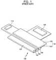
- FIG. 1is a perspective view of a configuration of a typical color FS-LCD.
- the FS-LCDincludes a liquid crystal panel 100 having a lower substrate 101 in which a thin film transistor (TFT) array (not shown) for switching is arranged to be connected to a plurality of gate lines, a plurality of data lines, and a plurality of common lines.
- the liquid crystal panelalso includes an upper substrate 103 in which a common electrode (not shown) is formed to provide a common voltage to the common lines.
- the liquid crystal panelfurther includes a liquid crystal (not shown) injected between the upper and lower substrates.
- the FS-LCDfurther includes a gate line driving circuit 110 for providing scan signals to the plurality of gate lines of the liquid crystal panel 100 , a data line driving circuit 120 for providing R, G, and B data signals to the data lines, and a back-light system 130 for providing light corresponding to three primary colors, namely, R, G, and B colors, to the liquid crystal panel 100 .
- the back-light system 130includes three back-lights 131 , 133 , and 135 respectively providing R, G, and B light, and a light guide plate 137 providing the R, G, and B light respectively emitted from the R, G, and B back-lights 131 , 133 , and 135 , to the liquid crystal of the liquid crystal panel 100 .
- a time interval of a single frame driven at 60 Hzis 16.7 ms ( 1/60 s).
- each subframehas a time interval of 5.56 ms ( 1/180 s).
- the time interval of one subframeis short enough to prevent its field change to be perceived by the human eye. Accordingly, the human eye sees the three subframes during the time interval of 16.7 ms as a single frame, resulting in the recognition of a composite color formed by the three primary colors to display the image.
- the response speed of the liquid crystalshould be fast and the corresponding switching speed for turning the R, G, and B back-lights on and off should also be relatively fast.
- light having uniform chromaticity and luminanceshould be emitted from each of the LEDs.
- FIG. 2is a schematic block diagram of a back-light driving circuit used in the FS-LCD shown in FIG. 1 .
- the back-light 220includes R, G, and B back-lights 221 , 223 , and 225 for sequentially emitting R, G, and B lights, respectively, per each subframe.
- a back-light driving circuit 210includes a driving voltage generator 211 sequentially generating a driving voltage VLED for driving the R, G, and B back-lights 221 , 223 , and 225 .
- the R back-light 221 emitting the R lightincludes a red LED (RLED), and the G back-light 223 emitting the G light includes a green LED (GLED), and the B back-light 225 emitting the B light includes a blue LED (BLED).
- RLEDred LED
- GLEDgreen LED
- BLEDblue LED
- the driving voltage generator 211generates the driving voltage VLED of a same level to the R, G, and B back-lights 221 , 223 , and 225 .
- the driving voltage VLED provided from the driving voltage generator 211is supplied to an anode electrode of the RLED of the R back-light 221 , an anode electrode of the GLED of the G back-light 223 , and an anode electrode of the BLED of the B back-light 225 .
- the back-light driving circuit 210further includes a luminance adjuster 212 that is serially connected between the back-light 220 and a ground, and that adjusts the luminance of light emitted from the back-light 220 .
- the luminance adjuster 212has a first variable resistor RVR that is connected between the ground and a cathode electrode of the RLED of the R back-light 221 and that adjusts the luminance of light emitted from the R back-light 221 , a second variable resistor GVR that is connected between the ground and a cathode electrode of the GLED of the G back-light 223 and that adjusts the luminance of light emitted from the G back-light 223 , and a third variable resistor BVR that is connected between the ground and a cathode electrode of the BLED of the B back-light 225 and that adjusts the luminance of light emitted from the B back-light 225 .
- variable resistors RVR, GVR, and BVR of the luminance adjuster 212are used to sequentially provide a driving voltage suitable for the RLED, a driving voltage suitable for the GLED, and a driving voltage suitable for the BLED. Accordingly, a suitable forward driving voltage is supplied to each of the red, green, and blue LEDs per each subframe, so that the R, G, and B back-lights 221 , 223 , and 225 sequentially emit light having a desired luminance.
- all of the R, G, and B back-lights 221 , 223 , 225are provided with the same driving voltage, such as, 4V, so that the luminance of light emitted from the R back-light 221 is adjusted by applying a forward driving voltage RVf suitable for the RLED using the first variable resistor RVR when the RLED is required to be driven.
- the luminance of light emitted from the G back-light 223is adjusted by applying a forward driving voltage GVf suitable for the GLED using the second variable resistor GVR when the GLED is required to be driven.
- the luminance of light emitted from the B back-light 225is adjusted by applying a forward driving voltage BVf suitable for the BLED using the third variable resistor BVR when the BLED is required to be driven.
- the luminancewas properly adjusted in the prior art by adjusting the variable resistor.
- LEDs forming the back-lightgenerally have a very large distribution of driving currents based on the particular LED product.
- the differing driving currents from LED to LEDcreate luminance non-uniformity that cannot be solved even when the luminance is adjusted using the variable resistor.
- chromaticityalso cannot be adjusted due to the differing driving current distributions from LED to LED.
- the various embodiments of the present inventionprovide a back-light driving circuit for driving an LED in an optimized condition that is capable of obtaining uniform luminance and chromaticity despite a driving current distribution of the LED.
- a liquid crystal displayincludes: an LCD driving circuit having one or more prestored driving conditions for a liquid crystal and one or more prestored driving conditions for each of a plurality of light emitting diodes (LEDs), the LCD driving circuit selecting and outputting a corresponding driving condition for the liquid crystal and a corresponding driving condition for at least one of the plurality of LEDs from among the one or more prestored driving conditions for the liquid crystal and the plurality of LEDs in response to a control signal.
- LEDslight emitting diodes
- the LCDalso includes a liquid crystal panel driven by the corresponding driving condition for the liquid crystal provided by the LCD driving circuit, a back-light including the at least one of the plurality of LEDs, and a back-light driving circuit for driving the at least one of the plurality of LEDs in the back-light based on the corresponding driving condition for the at least one of the plurality of LEDs provided by the LCD driving circuit.
- the LCD driving circuitmay output the corresponding driving condition suitable for the at least one of the plurality of LEDs based on a control signal provided from an external control device.
- the external control device for providing the control signal to the LCD driving circuitmay be a central processing unit (CPU) coupled to the LCD.
- the LCD driving circuitmay further include a data store prestoring the one or more driving conditions for the liquid crystal and the one or more driving conditions for each of the plurality of LEDs, and a controller having a temporary storage for temporarily storing data read out from the data store.
- the temporary storage of the LCD driving circuitmay be a register, and the data store of the LCD driving circuit may be an electrically erasable and programmable read only memory (EEPROM).
- the one or more driving conditions for each of the plurality of LEDs prestored in the first storage meansmay be ones for adjusting chromaticity and luminance of each of the plurality of LEDs, and the LCD driving circuit outputs the corresponding driving condition for the at least one of the plurality of LEDs for adjusting chromaticity and luminance of the at least one of the plurality of LEDs.
- the back-light driving circuitmay provide to the back-light a forward driving voltage corresponding to the corresponding driving condition for the at least one of the plurality of LEDs provided by the LCD driving circuit for adjusting the luminance of the at least one of the plurality of LEDs, and a pulse width modulation (PWM) signal corresponding to the corresponding driving condition for at least one of the plurality of LEDs for adjusting the chromaticity of the at least one of the plurality of LEDs.
- the corresponding driving condition for the liquid crystal prestored in the first storage meansmay include at least one of a driving condition based on temperature, a driving condition based on LCD mode, a driving condition based on driving frequency, a driving condition based on driving voltage, and a driving condition based on gray scale to be displayed.
- the back-light driving circuitmay further include a driving voltage generator receiving the corresponding driving condition for the at least one of the plurality of LEDs associated with a luminance of the at least one of the plurality of LEDs for generating a forward driving voltage of the at least one of the plurality of LEDs, and pulse width modulation (PWM) signal generator receiving the corresponding driving condition for the at least one of the plurality of LEDs associated with a chromaticity of the at least one of the plurality of LEDs for generating a PWM signal of the at least one of the plurality of LEDs.
- PWMpulse width modulation
- the liquid crystal panelmay further include a temperature sensor for sensing temperature of the liquid crystal panel, and a luminance and chromaticity sensor for sensing luminance and chromaticity of light transmitted through the liquid crystal.
- the LCD driving circuitsmay receive a temperature sensing signal and a luminance and chromaticity sensing signal, and may select and output an updated corresponding driving condition for the liquid crystal and an updated corresponding driving condition for the at least one of the plurality of LEDs from a data store, and may drive the liquid crystal panel and the at least one of the plurality of LEDs according to the updated corresponding driving conditions.
- a method for driving a liquid crystal displayincludes: prestoring one or more driving conditions for a liquid crystal included in a liquid crystal panel and one or more driving conditions for each of a plurality of LEDs capable of generating light for the liquid crystal panel; selecting a corresponding driving condition for at least one of the plurality of LEDs and a corresponding driving condition for the liquid crystal from among the one or more prestored driving conditions for the liquid crystal and the plurality of LEDs; driving the liquid crystal based on the corresponding driving condition for the liquid crystal; generating a driving signal corresponding to the corresponding driving condition for the at least one of the plurality of LEDs; and driving the at least one of the plurality of LEDs according to the generated driving signal.
- the one or more prestored driving conditions for each of the plurality of LEDsmay be ones for adjusting luminance and chromaticity of each of the plurality of LEDs, and may include a PWM signal for adjusting the chromaticity and a forward driving voltage for adjusting the luminance of each of the plurality of LEDs.
- the one or more prestored driving conditions for the liquid crystalincludes at least one of a driving condition based on temperature, a driving condition based on LCD mode, and a driving condition based on driving frequency, a driving condition based on driving voltage, and a driving condition based on gray scale to be displayed.
- the methodmay further include detecting a temperature of the liquid crystal, and luminance and chromaticity of light transmitted through the liquid crystal; selecting updated driving conditions for the liquid crystal and the at least one of the plurality of LEDs corresponding to the detected temperature, luminance, and chromaticity from among the one or more prestored driving conditions for the liquid crystal and the plurality of LEDs; and driving the liquid crystal panel and the at least one of the plurality of LEDs according to the updated driving conditions for the liquid crystal and the at least one of the plurality of LEDs.
- FIG. 1is a perspective view of a configuration of a typical color field sequential LCD
- FIG. 2is a schematic block diagram of a back-light driving circuit used in the conventional field sequential LCD of FIG. 1 ;
- FIG. 3is a block diagram illustrating a configuration of a field sequential LCD in accordance with embodiments of the present invention.
- FIG. 4is a schematic block diagram of a back-light driving circuit and an LCD driving circuit in a field sequential LCD according to an embodiment of the present invention.
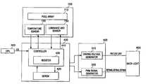
- FIG. 3is a block diagram illustrating a configuration of an FS-LCD in accordance with exemplary embodiments of the present invention.
- the illustrated LCDincludes an LCD driving circuit 400 , a back-light driving circuit 500 , a back-light 600 , and an LCD panel 700 .
- a processor 300such as, for example, a central processing unit (CPU), controls a main system connected to the LCD.
- CPUcentral processing unit
- the LCD driving circuit 400has a controller 410 and storage unit 420 .
- the storage unit 420which may be, for example, an electrically erasable and programmable read only memory (EEPROM), stores the driving conditions for driving the LEDs forming the back-light 600 on a per LED basis.
- the storage unit 420acts to store the driving conditions for driving the FS-LCD on a per LED product basis, and as such, stores a driving condition for the LED and a driving condition for the LCD panel.
- EEPROMelectrically erasable and programmable read only memory
- the driving condition for each LED stored in the storage unit 420includes a pulse width modulation (PWM) value and a driving voltage for driving the LED.
- PWMpulse width modulation
- the driving voltage and the PWM valueare values that are aimed to meet optimized driving conditions per LED product.
- the LCD driving conditionsinclude, without limitation, driving conditions based on temperature, LCD mode, driving frequency, driving voltage, required gray scale to be displayed, and the like. Other driving conditions required to drive the LED and LCD which will be apparent to those of skill in the art may also be stored. In this manner, one or more driving conditions based on external factors, driving current non-uniformity of the LED, and the like, are set in advance for each LED product and stored in the storage unit 420 .
- driving frequency, driving voltage, and turn-on time of the LED per temperatureare optimized and the optimized driving condition stored in the storage unit 420 for each temperature.
- the response speed of the liquid crystalbecomes slower when the temperature of the LCD panel is lower than a reference temperature, and the response speed of the liquid crystal becomes faster when the temperature of the LCD panel is higher than the reference temperature, calling for an adjustment in the corresponding driving frequency based on the detected temperature.
- the storage unit 420stores the corresponding driving frequency, driving voltage, and turn-on time of the LED per each stored temperature.
- the controller 410includes a register 430 .
- the register 430acts to temporarily store driving data suitable for the LEDs forming the back-light 600 which are read from the storage unit 420 when the LCD is driven.
- the back-light driving circuit 500includes a driving voltage generator 510 and PWM signal generator 520 .
- the driving voltage generator 510receives a driving condition associated with the luminance of the back-light from among the driving conditions provided from the LCD driving circuit 400 to sequentially generate driving voltages, RVf, GVf, and BVf respectively suitable for the R, G, and B LEDs of the back-light 600 .
- the PWM signal generator 520receives a driving condition associated with the chromaticity of the back-light from among the driving conditions provided from the LCD driving circuit 400 to sequentially generate PWM signals RPWM, GPWM, and BPWM respectively suitable for the R, G, and B LEDs of the back-light 600 .
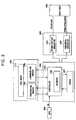
- the back-light 600has R, G, and B back-lights 601 , 603 , and 605 as shown in FIG. 4 .
- the R, G, and B back-lights 601 , 603 , and 605respectively have R, G. and B LEDs referred to as RLED, GLED, and BLED for respectively emitting R, G, and B lights having a predetermined luminance and a predetermined chromaticity which are driven by the PWM signals RPWM, GPWM, and BPWM, and the forward driving voltages RVf, GVf, and BVf provided from the back-light driving circuit 500 .
- the liquid crystal panel 700includes a pixel array 710 in which pixels are arranged in a matrix form, and gate and source drivers (not shown) for driving the pixels of the pixel array 710 .
- the liquid crystal panel 700further includes a temperature sensor 720 for sensing the temperature of the liquid crystal panel, and a luminance and chromaticity sensor 730 for measuring the luminance and the chromaticity of light transmitted through the liquid crystal of the liquid crystal panel 700 .
- the processor 300When the LCD is driven, the processor 300 reads out data from the storage unit 420 within the LCD driving circuit 400 .
- the processor 300transmits a control signal CS for reading out a driving condition for the LED and a driving condition for the LCD which are prestored in the storage unit 420 , to the LCD driving circuit 400 .
- the controller 410reads out the driving condition suitable for the corresponding LED from among the driving conditions prestored in the storage unit 420 on an LED basis, responsive to the control signal CS, and temporarily stores the read driving condition in the register 430 .
- the controller 410reads out the corresponding driving condition from among the driving conditions for the LCD panel 700 which are prestored in the storage unit 420 , and temporarily stores the read driving condition in the register 430 .
- the LCD driving circuit 400provides the driving condition stored in the register 430 for driving the liquid crystal to the pixel array of the LCD panel 700 , thereby driving the liquid crystal of the pixels arranged in the pixel array 710 via the driving condition.
- the LCD driving circuit 400also provides the driving condition for each LED stored in the register 430 to the back-light driving circuit 500 .
- the back-light driving circuit 500provides a driving condition for a forward driving voltage from among the driving conditions provided from the LCD driving circuit 400 to the driving voltage generator 510 , and a condition for the PWM signal to the PWM signal generator 520 . Accordingly, the driving voltage generator 510 generates the forward driving voltage of a particular LED, and the PWM signal generator 520 generates the PWM signal, in response to the corresponding driving condition.
- LEDs forming the back-light 600are driven by the PWM signals and the driving voltages provided from the back-light driving circuit 500 , so that the back-light 600 emits light having a predetermined chromaticity and a predetermined luminance.
- FIG. 4is a schematic block diagram of the back-light 600 and the back-light driving circuit 500 according to one embodiment of the invention.
- the back-light driving circuit 500drives the back-light 600 based on driving data provided for the LEDs by the LCD driving circuit 400 .
- the driving voltage generator 510receives the driving conditions for the forward driving voltage of the R, G, and B LEDs from among the driving conditions provided from the LCD driving circuit 400 as its input signal
- the PWM signal generator 520receives the driving conditions for the PWM signals of the R, G, and B LEDs as its input signal.
- the driving voltage generator 510receives the driving conditions for the forward driving voltages provided from the back-light driving circuit 400 to sequentially generate the driving voltages, namely, RVf, GVf, and BVf of the R, G, and B LEDs RLED, GLED, and BLED.
- the PWM signal generator 520receives the driving conditions for the PWM signals provided from the back-light driving circuit 400 to sequentially generate PWM signals, namely, RPWM, GPWM, and BPWM of the R, G, and B LEDs RLED, GLED, and BLED.
- the luminanceis adjusted by the driving voltage suitable for each of the R, G, and B LEDs, and the PWM value of each of the R, G, and B LEDs is also adjusted to thereby adjust a white balance of a color to be implemented.
- the forward driving voltage RVf suitable for the RLEDis provided so as to correspond to the driving condition provided from the LCD driving circuit 400 to drive the RLED in the first subframe.
- the forward driving voltage GVf suitable for the GLEDis then provided so as to correspond to the driving condition provided from the LCD driving circuit 400 to drive the GLED in the second subframe, and the forward driving voltage BVf suitable for the BLED is provided so as to correspond to the driving condition provided from the LCD driving circuit 400 to drive the BLED in the third subframe.
- the light emitting period of the RLEDis optimized to correspond to the driving condition provided from the LCD driving circuit 400 to have the driving current modulated by the PWM, and the light emitting periods of the GLED and BLED are also optimized to have their driving currents modulated by the PWM.
- the liquid crystal panel 700allows light to be emitted and transmitted through the R, G, and B LEDs RLED, GLED, and BLED by driving the liquid crystal of the pixel array to display a desired image.
- the LCDincludes the temperature sensor 720 in the liquid crystal panel 700 which may be, for example, a thermistor, that senses the temperature of the liquid crystal panel 700 and provides the temperature to the LCD driving circuit 400 under control of the controller 410 .
- the controller 410reads out a corresponding driving condition from the storage unit 420 each time there is a change in the temperature values input from the liquid crystal panel based on temperature sensed by the temperature sensor 720
- the LCDalso includes the luminance and chromaticity sensor 730 in the liquid crystal panel 700 that senses the luminance and the chromaticity of light transmitted through the liquid crystal according to conventional mechanisms. Data with respect to the sensed chromaticity and luminance is provided to the LCD driving circuit 400 under control of the controller 410 .
- the controller 410reads out a driving condition from the storage unit 420 again, corresponding to the chromaticity and luminance data provided from the liquid crystal panel.
- the LCD driving circuit 400provides the driving conditions for driving the liquid crystal and LED based on data associated with the sensed chromaticity, luminance, and temperature of the LCD panel 700 and the back-light driving circuit 500 .
- the liquid crystal panel 700 and the back-light driving circuit 500drive the pixel array 710 and the back-light 600 according to updated driving conditions provided from the LCD driving circuit 400 .
- temperature, luminance, and chromaticityare sensed and driving conditions suitable for them are provided to drive the liquid crystal panel and the back-light, so that the optimized driving condition may allow the liquid crystal and the back-light to be driven despite the driving current distribution of the LED or the temperature of the LCD panel. Accordingly, light having the optimized luminance and chromaticity may be emitted and the resultant image quality may also be enhanced.
- driving conditions for the liquid crystal and optimized driving conditionsare first stored in a memory device on a per LED basis, and desired driving conditions for the liquid crystal and LEDs are read out to drive the liquid crystal panel and the back-light, so that an image having desired luminance and chromaticity may be displayed regardless of the non-uniform driving currents of the LEDs.
Landscapes
- Physics & Mathematics (AREA)
- Engineering & Computer Science (AREA)
- General Physics & Mathematics (AREA)
- Computer Hardware Design (AREA)
- Theoretical Computer Science (AREA)
- Nonlinear Science (AREA)
- Chemical & Material Sciences (AREA)
- Crystallography & Structural Chemistry (AREA)
- Mathematical Physics (AREA)
- Optics & Photonics (AREA)
- Control Of Indicators Other Than Cathode Ray Tubes (AREA)
- Liquid Crystal Display Device Control (AREA)
- Liquid Crystal (AREA)
- Circuit Arrangement For Electric Light Sources In General (AREA)
Abstract
Description
Claims (17)
Applications Claiming Priority (3)
| Application Number | Priority Date | Filing Date | Title |
|---|---|---|---|
| KR10-2003-0085292 | 2003-11-27 | ||
| KR2003-85292 | 2003-11-27 | ||
| KR1020030085292AKR100741963B1 (en) | 2003-11-27 | 2003-11-27 | LCD and its driving method |
Publications (2)
| Publication Number | Publication Date |
|---|---|
| US20050116921A1 US20050116921A1 (en) | 2005-06-02 |
| US7728808B2true US7728808B2 (en) | 2010-06-01 |
Family
ID=34617327
Family Applications (1)
| Application Number | Title | Priority Date | Filing Date |
|---|---|---|---|
| US10/998,448Expired - Fee RelatedUS7728808B2 (en) | 2003-11-27 | 2004-11-29 | Field sequential liquid crystal display |
Country Status (4)
| Country | Link |
|---|---|
| US (1) | US7728808B2 (en) |
| JP (1) | JP3884040B2 (en) |
| KR (1) | KR100741963B1 (en) |
| CN (1) | CN100360999C (en) |
Cited By (6)
| Publication number | Priority date | Publication date | Assignee | Title |
|---|---|---|---|---|
| US20090091265A1 (en)* | 2007-10-05 | 2009-04-09 | Si-Joon Song | Backlight assembly and display device having the same |
| US20100194792A1 (en)* | 2007-09-18 | 2010-08-05 | Osram Gesellschaft Mit Beschraenkter Haftung | Illumination unit and method for driving the illumination unit |
| US20100231864A1 (en)* | 2009-03-12 | 2010-09-16 | Casio Computer Co., Ltd. | Projection apparatus, projection method and program |
| US20110291129A1 (en)* | 2008-11-14 | 2011-12-01 | Osram Opto Semiconductors Gmbh | Optoelectronic device |
| US20120105515A1 (en)* | 2009-07-07 | 2012-05-03 | Sharp Kabushiki Kaisha | Liquid crystal display device |
| US8710750B2 (en) | 2011-01-21 | 2014-04-29 | Mitsubishi Electric Corporation | Light source lighting device including a constant-current supply that is connected to a light source and supplies a constant current of a substantially constant magnitude to the light source, and luminaire |
Families Citing this family (47)
| Publication number | Priority date | Publication date | Assignee | Title |
|---|---|---|---|---|
| KR100659531B1 (en) | 2003-11-27 | 2006-12-19 | 삼성에스디아이 주식회사 | Backlight driving circuit |
| JP4587900B2 (en)* | 2004-08-02 | 2010-11-24 | 長野計器株式会社 | Two-wire signal transmission device |
| JP4550638B2 (en)* | 2005-03-22 | 2010-09-22 | シャープ株式会社 | Surface illumination device and liquid crystal display device including the same |
| US20100134521A1 (en)* | 2005-08-09 | 2010-06-03 | Koninklijke Philips Electronics, N.V. | Device comprising a liquid crystal display |
| JP4757585B2 (en)* | 2005-09-21 | 2011-08-24 | Nec液晶テクノロジー株式会社 | Light source unit and lighting device |
| KR100714427B1 (en)* | 2005-10-12 | 2007-05-07 | 삼성전자주식회사 | Display device and control method |
| JP2007108383A (en)* | 2005-10-13 | 2007-04-26 | Rohm Co Ltd | Image display device |
| JP4337804B2 (en)* | 2005-11-01 | 2009-09-30 | セイコーエプソン株式会社 | LIGHT EMITTING DEVICE, DRIVE CIRCUIT, DRIVE METHOD, AND ELECTRONIC DEVICE |
| KR101205535B1 (en)* | 2005-12-06 | 2012-11-27 | 삼성디스플레이 주식회사 | Apparatus for driving of light source and display device having the same and method of driving of light source |
| US7525611B2 (en)* | 2006-01-24 | 2009-04-28 | Astronautics Corporation Of America | Night vision compatible display backlight |
| US7557518B2 (en)* | 2006-01-24 | 2009-07-07 | Astronautics Corporation Of America | Solid-state, color-balanced backlight with wide illumination range |
| JP2007206282A (en)* | 2006-01-31 | 2007-08-16 | Toshiba Corp | Information processing apparatus and brightness control method |
| KR20070079455A (en) | 2006-02-02 | 2007-08-07 | 삼성전자주식회사 | Backlight unit having a plurality of light emitting elements and control method thereof |
| US8791645B2 (en) | 2006-02-10 | 2014-07-29 | Honeywell International Inc. | Systems and methods for controlling light sources |
| DE102006056057A1 (en)* | 2006-02-28 | 2007-09-06 | Samsung Electro - Mechanics Co., Ltd., Suwon | Drive device for a colored LED backlight |
| KR100736015B1 (en)* | 2006-04-21 | 2007-07-06 | 홀텍 세미컨덕터 인크. | Method and device for improving gray scale performance of light emitting diode |
| KR100883423B1 (en)* | 2006-05-09 | 2009-02-23 | (주)루미브라이트 | Drive control device of LED backlight unit |
| US7488087B2 (en)* | 2006-05-19 | 2009-02-10 | Honeywell International Inc. | Light guide and display including a light guide |
| KR101232616B1 (en)* | 2006-06-22 | 2013-02-13 | 삼성디스플레이 주식회사 | Liquid crystal display and control method thereof |
| TWI356387B (en)* | 2006-10-16 | 2012-01-11 | Au Optronics Corp | Modulation of the common voltage and controlling m |
| JP4607846B2 (en) | 2006-10-19 | 2011-01-05 | ソニー株式会社 | Light source device, light source driving device, light emission amount control device, and liquid crystal display device |
| JP2008140756A (en)* | 2006-11-02 | 2008-06-19 | Harison Toshiba Lighting Corp | Backlight device |
| KR100816289B1 (en)* | 2006-11-24 | 2008-03-24 | (주)다윈텍 | Color control method and LED backlight system using the same |
| CN101663703A (en)* | 2007-04-20 | 2010-03-03 | 夏普株式会社 | Lighting system and display device equipped with the same |
| JP2009042652A (en)* | 2007-08-10 | 2009-02-26 | Victor Co Of Japan Ltd | Liquid crystal display device and image display method thereof |
| GB2458095A (en)* | 2007-06-15 | 2009-09-09 | Sharp Kk | Solid state illumination system with elements employed as both light source and light sensor |
| US8378583B2 (en)* | 2007-06-22 | 2013-02-19 | Osram Gesellschaft Mit Beschraenkter Haftung | Feedforward control of semiconductor light sources |
| JP2009063878A (en)* | 2007-09-07 | 2009-03-26 | Stanley Electric Co Ltd | Liquid crystal display |
| CN101136188B (en)* | 2007-09-30 | 2010-04-21 | 友达光电股份有限公司 | Color sequence type liquid crystal display and driving method thereof |
| JP5220381B2 (en)* | 2007-10-16 | 2013-06-26 | ミネベア株式会社 | Surface lighting device |
| WO2009129650A1 (en)* | 2008-04-22 | 2009-10-29 | 光远科技股份有限公司 | Attenuating compensation method for led backlight plate of lcd and liauid crystal display |
| TWI416454B (en) | 2008-10-31 | 2013-11-21 | Dynascan Technology Corp | A method for compensating the uniformity of a liquid crystal display with a non - uniform backlight and the display |
| JP5314138B2 (en)* | 2009-07-03 | 2013-10-16 | シャープ株式会社 | Liquid crystal display device and light source control method |
| TW201102718A (en) | 2009-07-08 | 2011-01-16 | Dynascan Technology Corp | Decay fast detection method of LED backlight-board liquid crystal display and its display |
| KR101499369B1 (en) | 2010-12-08 | 2015-03-05 | 쇼오트 아게 | Display |
| DE202010013087U1 (en) | 2010-12-08 | 2011-02-24 | Schott Ag | display |
| DE102010061123A1 (en) | 2010-12-08 | 2012-06-14 | Schott Ag | Seven-segment-display for glass ceramic hob, has lighting element comprising two primary color-lamps i.e. laser diodes, where primary color intensity of lamps is corrected for compensating chromaticity coordinate offset of substrate |
| KR102067105B1 (en)* | 2011-12-28 | 2020-02-17 | 삼성전자주식회사 | Device and Method for Displaying Image, Device and Method for Supplying Power, Method for Adjusting Brightness of Contents |
| JP5692286B2 (en)* | 2013-06-05 | 2015-04-01 | カシオ計算機株式会社 | Projection apparatus, projection method, and program |
| CN103582264A (en)* | 2013-11-16 | 2014-02-12 | 中航华东光电有限公司 | High lighting efficiency LED drive system and method |
| CN104599643B (en)* | 2015-02-13 | 2017-07-14 | 合肥京东方光电科技有限公司 | Dimmable backlights source device, display device and its application method |
| CN105702201B (en)* | 2016-03-22 | 2018-07-20 | 深圳市艾比森光电股份有限公司 | A kind of LED display white balance control system and method |
| CN106228941B (en)* | 2016-08-23 | 2018-12-25 | 苏州亿科斯通电气有限公司 | A kind of method and device of spreading number pattern LCD temperature range |
| CN108154540B (en)* | 2017-12-22 | 2020-12-04 | 武汉华显光电技术有限公司 | Method and device for determining optimal chroma and brightness and computer readable storage medium |
| EP3899917A1 (en)* | 2018-12-21 | 2021-10-27 | Snap Inc. | Adaptive illuminator sequencing |
| CN109994086B (en)* | 2019-04-02 | 2021-06-01 | 深圳市浩升视讯有限公司 | Field-sequential driving liquid crystal display circuit and display device thereof |
| TWI738331B (en)* | 2020-05-11 | 2021-09-01 | 大陸商北京集創北方科技股份有限公司 | OLED display driving circuit and OLED display using it |
Citations (34)
| Publication number | Priority date | Publication date | Assignee | Title |
|---|---|---|---|---|
| JPS61198197A (en) | 1985-02-28 | 1986-09-02 | キヤノン株式会社 | Display unit |
| JPH08106264A (en) | 1994-10-04 | 1996-04-23 | Kinki Nippon Tetsudo Kk | Light control device |
| KR19990084247A (en) | 1998-05-02 | 1999-12-06 | 이종규 | AC power LED drive circuit |
| JP2000137465A (en) | 1998-11-04 | 2000-05-16 | Tokyo Electron Ind Co Ltd | Video signal processing circuit |
| JP2001257921A (en) | 2000-03-14 | 2001-09-21 | Ricoh Co Ltd | Digital camera |
| JP2001272956A (en) | 2000-03-27 | 2001-10-05 | Canon Inc | Liquid crystal display device and driving method thereof |
| JP2001337392A (en) | 2000-05-29 | 2001-12-07 | Ricoh Co Ltd | Illumination device system and projector device having the illumination device system |
| JP2001343935A (en) | 2000-10-06 | 2001-12-14 | Tatsuo Nakano | Light emitting diode display device |
| JP2002100485A (en)* | 2000-09-20 | 2002-04-05 | Nec Saitama Ltd | Color correction device and color correction method for RGB LED light emission |
| JP2002189220A (en) | 2000-12-21 | 2002-07-05 | Nippon Seiki Co Ltd | Light emitting device and liquid crystal display device having the same |
| US20020097000A1 (en)* | 2000-12-07 | 2002-07-25 | Philips Electronics North America Corporation | White led luminary light control system |
| JP2002231470A (en) | 2001-02-05 | 2002-08-16 | Pioneer Electronic Corp | Light emitting diode drive circuit |
| KR20020080249A (en) | 2001-03-30 | 2002-10-23 | 마츠시타 덴끼 산교 가부시키가이샤 | Display device |
| KR20020084125A (en) | 2000-12-12 | 2002-11-04 | 코닌클리즈케 필립스 일렉트로닉스 엔.브이. | Control and drive circuit arrangement |
| CN1384484A (en) | 2001-04-27 | 2002-12-11 | 本田技研工业株式会社 | Vehicle LCD |
| US6498592B1 (en)* | 1999-02-16 | 2002-12-24 | Sarnoff Corp. | Display tile structure using organic light emitting materials |
| KR20030007437A (en) | 2000-12-22 | 2003-01-23 | 가부시키가이샤 휴네트 | Liquid crystal drive apparatus and gradation display method |
| JP2003099015A (en) | 2000-12-22 | 2003-04-04 | Hunet Inc | Liquid crystal driving device and gradation display method |
| JP2003215534A (en) | 2002-01-23 | 2003-07-30 | Seiko Epson Corp | LCD backlight control device |
| US20030214242A1 (en)* | 2002-05-14 | 2003-11-20 | Roar Berg-Johansen | Systems and methods for controlling brightness of an avionics display |
| US20030231161A1 (en)* | 2002-06-17 | 2003-12-18 | Fuji Photo Film Co., Tld. | Image display device |
| US20040036672A1 (en)* | 2002-08-23 | 2004-02-26 | Lg.Philips Lcd Co., Ltd. | Field sequential liquid crystal display device and method of fabricating the same |
| JP2004086081A (en) | 2002-08-29 | 2004-03-18 | Citizen Electronics Co Ltd | Color display device and white balance adjustment method of color display device |
| US20040105053A1 (en)* | 2002-09-11 | 2004-06-03 | Optrex Corporation | Composite display device and a method for driving the same |
| US6762743B2 (en)* | 2001-07-16 | 2004-07-13 | Fujitsu Limited | Display device employing a field-sequential method |
| JP2004253309A (en) | 2003-02-21 | 2004-09-09 | Nichia Chem Ind Ltd | Special-purpose LED lighting with color rendering properties |
| JP2004309510A (en) | 2003-04-01 | 2004-11-04 | Hunet Inc | Device and method for driving led |
| US6831621B2 (en)* | 2001-07-27 | 2004-12-14 | Nec-Mitsubishi Electric Visual Systems Corporation | Liquid crystal display device |
| US20050035940A1 (en)* | 2003-08-12 | 2005-02-17 | Mihal Lazaridis | Monochromatic field sequential liquid crystal display |
| US20060071900A1 (en)* | 2004-10-05 | 2006-04-06 | Research In Motion Limited | Method for maintaining the white colour point in a field-sequential LCD over time |
| US20060097978A1 (en)* | 2004-10-22 | 2006-05-11 | Ng Kee Y | Field-sequential color display with feedback control |
| US7088334B2 (en)* | 2001-06-28 | 2006-08-08 | Matsushita Electric Industrial Co., Ltd. | Liquid crystal display device and manufacturing method thereof, and drive control method of lighting unit |
| US7208713B2 (en)* | 2002-12-13 | 2007-04-24 | Advanced Display Inc. | Light source unit and display device having luminance control based upon detected light values |
| US7468721B2 (en)* | 2002-11-20 | 2008-12-23 | Nec Display Solutions, Ltd. | Liquid crystal display |
Family Cites Families (1)
| Publication number | Priority date | Publication date | Assignee | Title |
|---|---|---|---|---|
| JPH0921993A (en)* | 1995-07-05 | 1997-01-21 | Sumitomo Wiring Syst Ltd | Back light driving device for liquid crystal display and its control method |
- 2003
- 2003-11-27KRKR1020030085292Apatent/KR100741963B1/ennot_activeExpired - Fee Related
- 2004
- 2004-11-25JPJP2004340948Apatent/JP3884040B2/ennot_activeExpired - Fee Related
- 2004-11-27CNCNB2004101038233Apatent/CN100360999C/ennot_activeExpired - Fee Related
- 2004-11-29USUS10/998,448patent/US7728808B2/ennot_activeExpired - Fee Related
Patent Citations (35)
| Publication number | Priority date | Publication date | Assignee | Title |
|---|---|---|---|---|
| JPS61198197A (en) | 1985-02-28 | 1986-09-02 | キヤノン株式会社 | Display unit |
| JPH08106264A (en) | 1994-10-04 | 1996-04-23 | Kinki Nippon Tetsudo Kk | Light control device |
| KR19990084247A (en) | 1998-05-02 | 1999-12-06 | 이종규 | AC power LED drive circuit |
| JP2000137465A (en) | 1998-11-04 | 2000-05-16 | Tokyo Electron Ind Co Ltd | Video signal processing circuit |
| US6498592B1 (en)* | 1999-02-16 | 2002-12-24 | Sarnoff Corp. | Display tile structure using organic light emitting materials |
| JP2001257921A (en) | 2000-03-14 | 2001-09-21 | Ricoh Co Ltd | Digital camera |
| JP2001272956A (en) | 2000-03-27 | 2001-10-05 | Canon Inc | Liquid crystal display device and driving method thereof |
| JP2001337392A (en) | 2000-05-29 | 2001-12-07 | Ricoh Co Ltd | Illumination device system and projector device having the illumination device system |
| JP2002100485A (en)* | 2000-09-20 | 2002-04-05 | Nec Saitama Ltd | Color correction device and color correction method for RGB LED light emission |
| JP2001343935A (en) | 2000-10-06 | 2001-12-14 | Tatsuo Nakano | Light emitting diode display device |
| US20020097000A1 (en)* | 2000-12-07 | 2002-07-25 | Philips Electronics North America Corporation | White led luminary light control system |
| US6888529B2 (en)* | 2000-12-12 | 2005-05-03 | Koninklijke Philips Electronics N.V. | Control and drive circuit arrangement for illumination performance enhancement with LED light sources |
| KR20020084125A (en) | 2000-12-12 | 2002-11-04 | 코닌클리즈케 필립스 일렉트로닉스 엔.브이. | Control and drive circuit arrangement |
| JP2002189220A (en) | 2000-12-21 | 2002-07-05 | Nippon Seiki Co Ltd | Light emitting device and liquid crystal display device having the same |
| KR20030007437A (en) | 2000-12-22 | 2003-01-23 | 가부시키가이샤 휴네트 | Liquid crystal drive apparatus and gradation display method |
| JP2003099015A (en) | 2000-12-22 | 2003-04-04 | Hunet Inc | Liquid crystal driving device and gradation display method |
| JP2002231470A (en) | 2001-02-05 | 2002-08-16 | Pioneer Electronic Corp | Light emitting diode drive circuit |
| KR20020080249A (en) | 2001-03-30 | 2002-10-23 | 마츠시타 덴끼 산교 가부시키가이샤 | Display device |
| CN1384484A (en) | 2001-04-27 | 2002-12-11 | 本田技研工业株式会社 | Vehicle LCD |
| US7088334B2 (en)* | 2001-06-28 | 2006-08-08 | Matsushita Electric Industrial Co., Ltd. | Liquid crystal display device and manufacturing method thereof, and drive control method of lighting unit |
| US6762743B2 (en)* | 2001-07-16 | 2004-07-13 | Fujitsu Limited | Display device employing a field-sequential method |
| US6831621B2 (en)* | 2001-07-27 | 2004-12-14 | Nec-Mitsubishi Electric Visual Systems Corporation | Liquid crystal display device |
| JP2003215534A (en) | 2002-01-23 | 2003-07-30 | Seiko Epson Corp | LCD backlight control device |
| US20030214242A1 (en)* | 2002-05-14 | 2003-11-20 | Roar Berg-Johansen | Systems and methods for controlling brightness of an avionics display |
| US20030231161A1 (en)* | 2002-06-17 | 2003-12-18 | Fuji Photo Film Co., Tld. | Image display device |
| US20040036672A1 (en)* | 2002-08-23 | 2004-02-26 | Lg.Philips Lcd Co., Ltd. | Field sequential liquid crystal display device and method of fabricating the same |
| JP2004086081A (en) | 2002-08-29 | 2004-03-18 | Citizen Electronics Co Ltd | Color display device and white balance adjustment method of color display device |
| US20040105053A1 (en)* | 2002-09-11 | 2004-06-03 | Optrex Corporation | Composite display device and a method for driving the same |
| US7468721B2 (en)* | 2002-11-20 | 2008-12-23 | Nec Display Solutions, Ltd. | Liquid crystal display |
| US7208713B2 (en)* | 2002-12-13 | 2007-04-24 | Advanced Display Inc. | Light source unit and display device having luminance control based upon detected light values |
| JP2004253309A (en) | 2003-02-21 | 2004-09-09 | Nichia Chem Ind Ltd | Special-purpose LED lighting with color rendering properties |
| JP2004309510A (en) | 2003-04-01 | 2004-11-04 | Hunet Inc | Device and method for driving led |
| US20050035940A1 (en)* | 2003-08-12 | 2005-02-17 | Mihal Lazaridis | Monochromatic field sequential liquid crystal display |
| US20060071900A1 (en)* | 2004-10-05 | 2006-04-06 | Research In Motion Limited | Method for maintaining the white colour point in a field-sequential LCD over time |
| US20060097978A1 (en)* | 2004-10-22 | 2006-05-11 | Ng Kee Y | Field-sequential color display with feedback control |
Non-Patent Citations (18)
| Title |
|---|
| Chinese Patent Office action dated Nov. 3, 2006, for CN 2004-10103823.3. |
| English translation of abstract for KR 10-1999-0084247 listed above. |
| English translation of Chinese Patent Office action dated Nov. 3, 2006 listed above. |
| English translation of Claims 1 & 2, for Japan Publication JP 61-198197, dated Sep. 2, 1986. |
| Korean Patent Abstracts, Publication No. 1020020080249 A, dated Oct. 23, 2002, in the name of Masanori Kimura,et al. |
| Patent Abstract of Japan, Publication No. 2004-086081, dated Mar. 18, 2004, in the name of Sasuga Masatoshi. |
| Patent Abstract of Japan, Publication No. 2004-309510, dated Nov. 11, 2004, in the name of Ozaki Yutaka. |
| Patent Abstracts of Japan, Publication 08-106264, dated Apr. 23, 1996, in the name of Yutaka Kashiwabara et al. |
| Patent Abstracts of Japan, Publication 2000-137465, dated May 16, 2000, in the name of Michio Suzuki. |
| Patent Abstracts of Japan, Publication 2002-189220, dated Jul. 5, 2002, in the name of Takashi Yamazoe. |
| Patent Abstracts of Japan, Publication 2002-231470, dated Aug. 16, 2002, in the name of Takao Inoue. |
| Patent Abstracts of Japan, Publication No. 2001-257921, dated Sep. 21, 2001, in the name of Kazumasa Aoki. |
| Patent Abstracts of Japan, Publication No. 2001-272956, dated Oct. 5, 2001, in the name of Hideo Mori, et al. |
| Patent Abstracts of Japan, Publication No. 2001-337392, dated Dec. 7, 2001, in the name of Kenji Kameyama et al. |
| Patent Abstracts of Japan, Publication No. 2001-343935, dated Dec. 14, 2001, in the name of Tatsuo Nakano. |
| Patent Abstracts of Japan, Publication No. 2002-328048, dated Nov. 15, 2002, in the name of Atsushi Hatayama et al. (Corresponds to CN 1384484A listed above). |
| Patent Abstracts of Japan, Publication No. 2003-099015, dated Apr. 4, 2003, in the name of Yutaka Ozaki. |
| Patent Abstracts of Japan, Publication No. 2004-253309, dated Sep. 9, 2004, in the name of Tomoaki Inuzuka. |
Cited By (10)
| Publication number | Priority date | Publication date | Assignee | Title |
|---|---|---|---|---|
| US20100194792A1 (en)* | 2007-09-18 | 2010-08-05 | Osram Gesellschaft Mit Beschraenkter Haftung | Illumination unit and method for driving the illumination unit |
| US20090091265A1 (en)* | 2007-10-05 | 2009-04-09 | Si-Joon Song | Backlight assembly and display device having the same |
| US7990360B2 (en)* | 2007-10-05 | 2011-08-02 | Samsung Electronics Co., Ltd. | Backlight assembly and display device having the same |
| US20110291129A1 (en)* | 2008-11-14 | 2011-12-01 | Osram Opto Semiconductors Gmbh | Optoelectronic device |
| US9398664B2 (en)* | 2008-11-14 | 2016-07-19 | Osram Opto Semiconductors Gmbh | Optoelectronic device that emits mixed light |
| US20100231864A1 (en)* | 2009-03-12 | 2010-09-16 | Casio Computer Co., Ltd. | Projection apparatus, projection method and program |
| US9052576B2 (en) | 2009-03-12 | 2015-06-09 | Casio Computer Co., Ltd. | Projection apparatus which adjusts power to light-emitting devices to correct a decrease in luminance due to heat generation, and projection method and program for the same |
| US20120105515A1 (en)* | 2009-07-07 | 2012-05-03 | Sharp Kabushiki Kaisha | Liquid crystal display device |
| US8797253B2 (en)* | 2009-07-07 | 2014-08-05 | Sharp Kabushiki Kaisha | Liquid crystal display device |
| US8710750B2 (en) | 2011-01-21 | 2014-04-29 | Mitsubishi Electric Corporation | Light source lighting device including a constant-current supply that is connected to a light source and supplies a constant current of a substantially constant magnitude to the light source, and luminaire |
Also Published As
| Publication number | Publication date |
|---|---|
| CN100360999C (en) | 2008-01-09 |
| KR20050051501A (en) | 2005-06-01 |
| JP2005157387A (en) | 2005-06-16 |
| KR100741963B1 (en) | 2007-07-23 |
| CN1621903A (en) | 2005-06-01 |
| US20050116921A1 (en) | 2005-06-02 |
| JP3884040B2 (en) | 2007-02-21 |
Similar Documents
| Publication | Publication Date | Title |
|---|---|---|
| US7728808B2 (en) | Field sequential liquid crystal display | |
| US7391407B2 (en) | Back-light driving circuit in field sequential liquid crystal display | |
| US7652655B2 (en) | Backlight driver circuit and liquid crystal display device having the same | |
| US7671542B2 (en) | Color control of multi-zone LED backlight | |
| RU2419888C1 (en) | Backlight device, method of controlling backlight and liquid-crystal display device | |
| EP1950730B1 (en) | Backlight and liquid crystal display using the same | |
| US7982706B2 (en) | Backlight device, method of driving backlight and liquid crystal display apparatus | |
| KR101493492B1 (en) | Backlight unit, liquid crystal display including the same and driving method thereof | |
| US8395578B2 (en) | Backlight unit and liquid-crystal display device using the same | |
| CN101339743B (en) | Backlight device, method of driving backlight device and liquid crystal display apparatus | |
| JP4882657B2 (en) | Backlight control device, backlight control method, and liquid crystal display device | |
| EP2075785A1 (en) | Light source system and display | |
| JP5525783B2 (en) | Light source driving device and display device including the same | |
| JP2007287422A (en) | Backlight system, liquid crystal display device, and backlight adjustment method | |
| KR20090035286A (en) | Back light assembly and display device having same | |
| WO2009000182A1 (en) | Methods and apparatus for backlight calibration | |
| US8358263B2 (en) | Color control of a backlighting system | |
| KR101482069B1 (en) | A light source local dimming method, a light source device for performing the same, and a display device having the light source device | |
| KR101502367B1 (en) | Back light unit and liquid crystal display device using the same and driving method thereof | |
| JP2007134194A (en) | Light emitting element control device, light emitting element backlight device, liquid crystal display device, and white balance control method | |
| KR101067940B1 (en) | Drive part of LCD | |
| KR100712119B1 (en) | Field-sequentially driven liquid crystal display with backlight controller for uniform brightness | |
| KR20080011852A (en) | Light emitting device, liquid crystal display device having same and driving method thereof |
Legal Events
| Date | Code | Title | Description |
|---|---|---|---|
| AS | Assignment | Owner name:SAMSUNG SDI CO., LTD., KOREA, REPUBLIC OF Free format text:ASSIGNMENT OF ASSIGNORS INTEREST;ASSIGNOR:KIM, TAE-SOO;REEL/FRAME:015638/0638 Effective date:20041119 Owner name:SAMSUNG SDI CO., LTD.,KOREA, REPUBLIC OF Free format text:ASSIGNMENT OF ASSIGNORS INTEREST;ASSIGNOR:KIM, TAE-SOO;REEL/FRAME:015638/0638 Effective date:20041119 | |
| AS | Assignment | Owner name:SAMSUNG MOBILE DISPLAY CO., LTD., KOREA, REPUBLIC Free format text:ASSIGNMENT OF ASSIGNORS INTEREST;ASSIGNOR:SAMSUNG SDI CO., LTD.;REEL/FRAME:021973/0313 Effective date:20081210 Owner name:SAMSUNG MOBILE DISPLAY CO., LTD.,KOREA, REPUBLIC O Free format text:ASSIGNMENT OF ASSIGNORS INTEREST;ASSIGNOR:SAMSUNG SDI CO., LTD.;REEL/FRAME:021973/0313 Effective date:20081210 | |
| FEPP | Fee payment procedure | Free format text:PAYOR NUMBER ASSIGNED (ORIGINAL EVENT CODE: ASPN); ENTITY STATUS OF PATENT OWNER: LARGE ENTITY | |
| REMI | Maintenance fee reminder mailed | ||
| LAPS | Lapse for failure to pay maintenance fees | ||
| STCH | Information on status: patent discontinuation | Free format text:PATENT EXPIRED DUE TO NONPAYMENT OF MAINTENANCE FEES UNDER 37 CFR 1.362 | |
| FP | Lapsed due to failure to pay maintenance fee | Effective date:20140601 |