US7728316B2 - Integrated proximity sensor and light sensor - Google Patents
Integrated proximity sensor and light sensorDownload PDFInfo
- Publication number
- US7728316B2 US7728316B2US11/600,344US60034406AUS7728316B2US 7728316 B2US7728316 B2US 7728316B2US 60034406 AUS60034406 AUS 60034406AUS 7728316 B2US7728316 B2US 7728316B2
- Authority
- US
- United States
- Prior art keywords
- emitter
- data
- processing system
- proximity
- light
- Prior art date
- Legal status (The legal status is an assumption and is not a legal conclusion. Google has not performed a legal analysis and makes no representation as to the accuracy of the status listed.)
- Expired - Lifetime
Links
Images


Classifications
- H—ELECTRICITY
- H04—ELECTRIC COMMUNICATION TECHNIQUE
- H04W—WIRELESS COMMUNICATION NETWORKS
- H04W52/00—Power management, e.g. Transmission Power Control [TPC] or power classes
- H04W52/02—Power saving arrangements
- H04W52/0209—Power saving arrangements in terminal devices
- H04W52/0261—Power saving arrangements in terminal devices managing power supply demand, e.g. depending on battery level
- H04W52/0267—Power saving arrangements in terminal devices managing power supply demand, e.g. depending on battery level by controlling user interface components
- H04W52/027—Power saving arrangements in terminal devices managing power supply demand, e.g. depending on battery level by controlling user interface components by controlling a display operation or backlight unit
- G—PHYSICS
- G06—COMPUTING OR CALCULATING; COUNTING
- G06F—ELECTRIC DIGITAL DATA PROCESSING
- G06F3/00—Input arrangements for transferring data to be processed into a form capable of being handled by the computer; Output arrangements for transferring data from processing unit to output unit, e.g. interface arrangements
- G06F3/01—Input arrangements or combined input and output arrangements for interaction between user and computer
- G06F3/03—Arrangements for converting the position or the displacement of a member into a coded form
- G06F3/0304—Detection arrangements using opto-electronic means
- H—ELECTRICITY
- H04—ELECTRIC COMMUNICATION TECHNIQUE
- H04M—TELEPHONIC COMMUNICATION
- H04M1/00—Substation equipment, e.g. for use by subscribers
- H04M1/60—Substation equipment, e.g. for use by subscribers including speech amplifiers
- H04M1/6033—Substation equipment, e.g. for use by subscribers including speech amplifiers for providing handsfree use or a loudspeaker mode in telephone sets
- H04M1/6041—Portable telephones adapted for handsfree use
- H04M1/605—Portable telephones adapted for handsfree use involving control of the receiver volume to provide a dual operational mode at close or far distance from the user
- H—ELECTRICITY
- H04—ELECTRIC COMMUNICATION TECHNIQUE
- H04M—TELEPHONIC COMMUNICATION
- H04M1/00—Substation equipment, e.g. for use by subscribers
- H04M1/72—Mobile telephones; Cordless telephones, i.e. devices for establishing wireless links to base stations without route selection
- H04M1/724—User interfaces specially adapted for cordless or mobile telephones
- H04M1/72448—User interfaces specially adapted for cordless or mobile telephones with means for adapting the functionality of the device according to specific conditions
- H04M1/72454—User interfaces specially adapted for cordless or mobile telephones with means for adapting the functionality of the device according to specific conditions according to context-related or environment-related conditions
- H—ELECTRICITY
- H04—ELECTRIC COMMUNICATION TECHNIQUE
- H04W—WIRELESS COMMUNICATION NETWORKS
- H04W52/00—Power management, e.g. Transmission Power Control [TPC] or power classes
- H04W52/02—Power saving arrangements
- H04W52/0209—Power saving arrangements in terminal devices
- H04W52/0251—Power saving arrangements in terminal devices using monitoring of local events, e.g. events related to user activity
- H04W52/0254—Power saving arrangements in terminal devices using monitoring of local events, e.g. events related to user activity detecting a user operation or a tactile contact or a motion of the device
- G—PHYSICS
- G09—EDUCATION; CRYPTOGRAPHY; DISPLAY; ADVERTISING; SEALS
- G09G—ARRANGEMENTS OR CIRCUITS FOR CONTROL OF INDICATING DEVICES USING STATIC MEANS TO PRESENT VARIABLE INFORMATION
- G09G2330/00—Aspects of power supply; Aspects of display protection and defect management
- G09G2330/02—Details of power systems and of start or stop of display operation
- G09G2330/021—Power management, e.g. power saving
- G—PHYSICS
- G09—EDUCATION; CRYPTOGRAPHY; DISPLAY; ADVERTISING; SEALS
- G09G—ARRANGEMENTS OR CIRCUITS FOR CONTROL OF INDICATING DEVICES USING STATIC MEANS TO PRESENT VARIABLE INFORMATION
- G09G2360/00—Aspects of the architecture of display systems
- G09G2360/14—Detecting light within display terminals, e.g. using a single or a plurality of photosensors
- G09G2360/144—Detecting light within display terminals, e.g. using a single or a plurality of photosensors the light being ambient light
- G—PHYSICS
- G09—EDUCATION; CRYPTOGRAPHY; DISPLAY; ADVERTISING; SEALS
- G09G—ARRANGEMENTS OR CIRCUITS FOR CONTROL OF INDICATING DEVICES USING STATIC MEANS TO PRESENT VARIABLE INFORMATION
- G09G3/00—Control arrangements or circuits, of interest only in connection with visual indicators other than cathode-ray tubes
- G09G3/20—Control arrangements or circuits, of interest only in connection with visual indicators other than cathode-ray tubes for presentation of an assembly of a number of characters, e.g. a page, by composing the assembly by combination of individual elements arranged in a matrix no fixed position being assigned to or needed to be assigned to the individual characters or partial characters
- G09G3/34—Control arrangements or circuits, of interest only in connection with visual indicators other than cathode-ray tubes for presentation of an assembly of a number of characters, e.g. a page, by composing the assembly by combination of individual elements arranged in a matrix no fixed position being assigned to or needed to be assigned to the individual characters or partial characters by control of light from an independent source
- G09G3/3406—Control of illumination source
- H—ELECTRICITY
- H04—ELECTRIC COMMUNICATION TECHNIQUE
- H04M—TELEPHONIC COMMUNICATION
- H04M1/00—Substation equipment, e.g. for use by subscribers
- H04M1/02—Constructional features of telephone sets
- H04M1/0202—Portable telephone sets, e.g. cordless phones, mobile phones or bar type handsets
- H04M1/0206—Portable telephones comprising a plurality of mechanically joined movable body parts, e.g. hinged housings
- H04M1/0208—Portable telephones comprising a plurality of mechanically joined movable body parts, e.g. hinged housings characterized by the relative motions of the body parts
- H04M1/0214—Foldable telephones, i.e. with body parts pivoting to an open position around an axis parallel to the plane they define in closed position
- H—ELECTRICITY
- H04—ELECTRIC COMMUNICATION TECHNIQUE
- H04M—TELEPHONIC COMMUNICATION
- H04M1/00—Substation equipment, e.g. for use by subscribers
- H04M1/02—Constructional features of telephone sets
- H04M1/0202—Portable telephone sets, e.g. cordless phones, mobile phones or bar type handsets
- H04M1/0206—Portable telephones comprising a plurality of mechanically joined movable body parts, e.g. hinged housings
- H04M1/0241—Portable telephones comprising a plurality of mechanically joined movable body parts, e.g. hinged housings using relative motion of the body parts to change the operational status of the telephone set, e.g. switching on/off, answering incoming call
- H04M1/0245—Portable telephones comprising a plurality of mechanically joined movable body parts, e.g. hinged housings using relative motion of the body parts to change the operational status of the telephone set, e.g. switching on/off, answering incoming call using open/close detection
- H—ELECTRICITY
- H04—ELECTRIC COMMUNICATION TECHNIQUE
- H04M—TELEPHONIC COMMUNICATION
- H04M1/00—Substation equipment, e.g. for use by subscribers
- H04M1/02—Constructional features of telephone sets
- H04M1/22—Illumination; Arrangements for improving the visibility of characters on dials
- H—ELECTRICITY
- H04—ELECTRIC COMMUNICATION TECHNIQUE
- H04M—TELEPHONIC COMMUNICATION
- H04M2250/00—Details of telephonic subscriber devices
- H04M2250/12—Details of telephonic subscriber devices including a sensor for measuring a physical value, e.g. temperature or motion
- H—ELECTRICITY
- H04—ELECTRIC COMMUNICATION TECHNIQUE
- H04M—TELEPHONIC COMMUNICATION
- H04M2250/00—Details of telephonic subscriber devices
- H04M2250/16—Details of telephonic subscriber devices including more than one display unit
- H—ELECTRICITY
- H04—ELECTRIC COMMUNICATION TECHNIQUE
- H04M—TELEPHONIC COMMUNICATION
- H04M2250/00—Details of telephonic subscriber devices
- H04M2250/22—Details of telephonic subscriber devices including a touch pad, a touch sensor or a touch detector
- Y—GENERAL TAGGING OF NEW TECHNOLOGICAL DEVELOPMENTS; GENERAL TAGGING OF CROSS-SECTIONAL TECHNOLOGIES SPANNING OVER SEVERAL SECTIONS OF THE IPC; TECHNICAL SUBJECTS COVERED BY FORMER USPC CROSS-REFERENCE ART COLLECTIONS [XRACs] AND DIGESTS
- Y02—TECHNOLOGIES OR APPLICATIONS FOR MITIGATION OR ADAPTATION AGAINST CLIMATE CHANGE
- Y02D—CLIMATE CHANGE MITIGATION TECHNOLOGIES IN INFORMATION AND COMMUNICATION TECHNOLOGIES [ICT], I.E. INFORMATION AND COMMUNICATION TECHNOLOGIES AIMING AT THE REDUCTION OF THEIR OWN ENERGY USE
- Y02D30/00—Reducing energy consumption in communication networks
- Y02D30/70—Reducing energy consumption in communication networks in wireless communication networks
Definitions
- This inventionrelates to the field of portable devices and, in particular, to systems and methods for sensing or determining user activities and responding to the user's activities.
- Portable devicessuch as cell phones, are becoming increasingly common. These portable devices have grown more complex over time, incorporating many features including, for example, MP3 player capabilities, web browsing capabilities, capabilities of personal digital assistants (PDAs) and the like.
- MP3 player capabilitiessuch as cell phones
- web browsing capabilitiessuch as web browsing capabilities
- PDAspersonal digital assistants
- Some of these portable devicesmay include multiple sensors which are used to detect the environment or context associated with these portable devices.
- U.S. patent application publication no. 2005/0219228describes a device which includes many sensors, including a proximity sensor and a light sensor. The outputs from the sensors are processed to determine a device context.
- the light sensordetects ambient light levels and the proximity sensor detects a proximity to an object, such as a user's ear or face. In this case, there are two separate sensors which require two openings in the housing of the device.
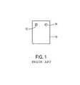
- FIG. 1which shows a device 10 .
- the device 10includes a proximity sensor 12 mounted on a surface of the device 10 and an ambient light sensor 14 also mounted on the surface of the device 10 . Each of these sensors is distinct from the other, and separate openings in the surface are needed for each sensor.
- the various apparatuses and methods described hereinrelate to an apparatus which senses proximity and detects light, such as ambient light, and to systems, such as data processing systems, which use an apparatus which senses proximity and also detects light, such as ambient light.
- an apparatuswhich both senses proximity and detects light, includes an emitter of electromagnetic radiation and a detector of electromagnetic radiation.
- the detectoris configured to detect electromagnetic radiation, such as infrared (IR) light, emitted from the emitter when the apparatus is configured to sense proximity.
- the emittermay be disabled at least temporarily to allow the detector to detect electromagnetic radiation from a source other than the emitter. In this case, the emitter may be disabled by turning power off for the emitter or by closing a shutter on the emitter to block radiation from being emitted to the environment or by other implementations which prevent the emitter's radiation from being detected by the detector.
- the output from the detectormay be processed, using known signal processing algorithms, to subtract the effect of the radiation detected from the emitter in order to produce a resultant signal which represents the radiation from sources other than the emitter. This may involve measuring proximity first to determine an amplitude and phase of a known signal from the emitter (e.g. a square wave signal with a known frequency and pulse width) and then subtracting this known signal from a detected signal from the detector. Alternatively, if the emitter has sufficiently long “on” and “off” pulses during its square wave signal, the detector may be configured to measure ambient light during one or more of the “off” pulses without having to turn off the emitter.
- a known signal from the emittere.g. a square wave signal with a known frequency and pulse width
- the detectormay be configured to measure ambient light during one or more of the “off” pulses without having to turn off the emitter.
- a data processing systemincludes a proximity sensor to sense a proximity and to detect electromagnetic radiation when the proximity sensor is not sensing proximity.
- the proximity sensorincludes an emitter of electromagnetic radiation (e.g. IR light) and a detector of electromagnetic radiation from the emitter when the sensor is sensing proximity.
- the data processing systemalso may include at least one of a display or an input device and also may include at least one processor which is coupled to the proximity sensor and which is configured to determine, based at least upon data from the proximity sensor, whether to modify a state (e.g. a setting) of the data processing system.
- the data from the proximity sensormay include data relating to proximity and data relating to ambient light measurements or other light measurements.
- the processormay modify the state of the data processing system automatically in response to a user activity, relative to the system, as indicated by the data from the proximity sensor, including both proximity data and ambient light data.
- a method of operating a proximity sensorwhich provides light sensor capabilities, includes emitting light from an emitter of the proximity sensor, detecting, through a detector of the proximity sensor, light from the emitter, and sensing light, from a source other than the emitter, at the detector.
- the detectoris configured, in a proximity sensing mode, to detect light from the emitter to determine proximity.
- the detectormay sense light from a source other than the emitter by having the emitter disabled or by having its output signal processed to remove the effect of light from the emitter.
- FIG. 1shows an example of a prior art device which includes two separate sensors
- FIG. 2is a perspective view of a portable device in accordance with one embodiment of the present invention.
- FIG. 3is a perspective view of a portable device in accordance with one embodiment of the present invention.
- FIG. 4is a perspective view of a portable device in accordance with one embodiment of the present invention.
- FIG. 5Ais a perspective view of a portable device in a first configuration (e.g. in an open configuration) in accordance with one embodiment of the present invention
- FIG. 5Bis a perspective view of the portable device of FIG. 5A in a second configuration (e.g. a closed configuration) in accordance with one embodiment of the present invention
- FIG. 6is a block diagram of a system in which embodiments of the present invention can be implemented.
- FIG. 7Ais a schematic side view of a proximity sensor in accordance with one embodiment of the present invention.
- FIG. 7Bis a schematic side view of an alternative proximity sensor in accordance with one embodiment of the present invention.
- FIG. 7Cis a flow chart which shows a method of operating a proximity sensor which is capable of detecting light from a source other than the emitter of the proximity sensor;
- FIG. 7Dshows an example of a proximity sensor with associated logic
- FIG. 8is a block diagram of inputs and outputs for logic, such as artificial intelligence logic, in accordance with embodiments of the present invention.
- FIGS. 9A-Care views of user activities in accordance with embodiments of the present invention.
- FIG. 10is a flow chart of a method that includes automated responses to user activity in accordance with embodiments of the present invention.
- FIGS. 11A-Fare flow charts of combinations of sensing to determine user activity and performing automated responses in accordance with embodiments of the present invention.
- FIG. 12is a block diagram of a digital processing system in accordance with one embodiment of the present invention.
- the present inventioncan relate to an apparatus for performing one or more of the operations described herein.
- This apparatusmay be specially constructed for the required purposes, or it may comprise a general purpose computer selectively activated or reconfigured by a computer program stored in the computer.
- a computer programmay be stored in a machine (e.g. computer) readable storage medium, such as, but is not limited to, any type of disk including floppy disks, optical disks, CD-ROMs, and magnetic-optical disks, read-only memories (ROMs), random access memories (RAMs), erasable programmable ROMs (EPROMs), electrically erasable programmable ROMs (EEPROMs), magnetic or optical cards, or any type of media suitable for storing electronic instructions, and each coupled to a bus.
- ROMsread-only memories
- RAMsrandom access memories
- EPROMserasable programmable ROMs
- EEPROMselectrically erasable programmable ROMs
- magnetic or optical cardsor any type of media suitable
- a machine-readable mediumincludes any mechanism for storing or transmitting information in a form readable by a machine (e.g., a computer).
- a machine-readable mediumincludes read only memory (“ROM”); random access memory (“RAM”); magnetic disk storage media; optical storage media; flash memory devices; electrical, optical, acoustical or other form of propagated signals (e.g., carrier waves, infrared signals, digital signals, etc.); etc.
- At least certain embodiments of the present inventionsinclude one or more sensors to monitor user activity. At least certain embodiments of the present inventions also include automatically changing a state of the portable device based on user activity, such as, for example, automatically activating or deactivating a backlight of a display device of the portable device or setting an input device of the portable device to a particular state, based on certain predetermined user activities.
- At least certain embodiments of the inventionsmay be part of a digital media player, such as a portable music and/or video media player, which may include a media processing system to present the media, a storage device to store the media and may further include a radio frequency (RF) transceiver (e.g., an RF transceiver for a cellular telephone) coupled with an antenna system and the media processing system.
- RFradio frequency
- media stored on a remote storage devicemay be transmitted to the media player through the RF transceiver.
- the mediamay be, for example, one or more of music or other audio, still pictures, or motion pictures.
- the portable media playermay include a media selection device, such as a click wheel input device on an iPod® or iPod Nano® media player from Apple Computer, Inc. of Cupertino, Calif., a touch screen input device, pushbutton device, movable pointing input device or other input device.
- the media selection devicemay be used to select the media stored on the storage device and/or the remote storage device.
- the portable media playermay, in at least certain embodiments, include a display device which is coupled to the media processing system to display titles or other indicators of media being selected through the input device and being presented, either through a speaker or earphone(s), or on the display device, or on both display device and a speaker or earphone(s). Examples of a portable media player are described in published U.S. patent application Ser. Nos. 2003/0095096 and 2004/0224638, both of which are incorporated herein by reference.
- Embodiments of the inventions described hereinmay be part of other types of data processing systems, such as, for example, entertainment systems or personal digital assistants (PDAs), or general purpose computer systems, or special purpose computer systems, or an embedded device within another device, or cellular telephones which do not include media players, or devices which combine aspects or functions of these devices (e.g., a media player, such as an iPod®, combined with a PDA, an entertainment system, and a cellular telephone in one portable device).
- PDAspersonal digital assistants
- an embedded devicewithin another device
- cellular telephoneswhich do not include media players, or devices which combine aspects or functions of these devices (e.g., a media player, such as an iPod®, combined with a PDA, an entertainment system, and a cellular telephone in one portable device).
- FIG. 2illustrates a portable device 30 according to one embodiment of the invention.
- FIG. 2shows a wireless device in a telephone configuration having a “candy-bar” style.
- the wireless device 30may include a housing 32 , a display device 34 , an input device 36 which may be an alphanumeric keypad, a speaker 38 , a microphone 40 and an antenna 42 .
- the wireless device 30also may include a proximity sensor 44 and an accelerometer 46 . It will be appreciated that the embodiment of FIG. 2 may use more or fewer sensors and may have a different form factor from the form factor shown in FIG. 2 .
- the display device 34is shown positioned at an upper portion of the housing 32
- the input device 36is shown positioned at a lower portion of the housing 32
- the antenna 42is shown extending from the housing 32 at an upper portion of the housing 32 .
- the speaker 38is also shown at an upper portion of the housing 32 above the display device 34 .
- the microphone 40is shown at a lower portion of the housing 32 , below the input device 36 . It will be appreciated that the speaker 38 and microphone 40 can be positioned at any location on the housing, but are typically positioned in accordance with a user's ear and mouth, respectively.
- the proximity sensor 44is shown at or near the speaker 38 and at least partially within the housing 32 .
- the accelerometer 46is shown at a lower portion of the housing 32 and within the housing 32 . It will be appreciated that the particular locations of the above-described features may vary in alternative embodiments.
- the display device 34may be, for example, a liquid crystal display (LCD) which does not include the ability to accept inputs or a touch input screen which also includes an LCD.
- the input device 36may include, for example, buttons, switches, dials, sliders, keys or keypad, navigation pad, touch pad, touch screen, and the like.
- speaker 38Any well-known speaker, microphone and antenna can be used for speaker 38 , microphone 40 and antenna 42 , respectively.
- the proximity sensor 44may detect location (e.g. at least one of X, Y, Z), direction of motion, speed, etc. of objects relative to the wireless device 30 .
- a location of an object relative to the wireless devicecan be represented as a distance in at least certain embodiments.
- the proximity sensormay generate location or movement data or both, which may be used to determine the location of objects relative to the portable device 30 and/or proximity sensor 44 .
- An example of a proximity sensoris shown in FIG. 7A .
- a processing device(not shown) is coupled to the proximity sensor(s) 44 .
- the processing devicemay be used to determine the location of objects relative to the portable device 30 or proximity sensor 44 or both based on the location and/or movement data provided by the proximity sensor 44 .
- the proximity sensormay continuously or periodically monitor the object location.
- the proximity sensormay also be able to determine the type of object it is detecting.
- the accelerometer 46is able to detect a movement including an acceleration or de-acceleration of the wireless device.
- the accelerometer 46may generate movement data for multiple dimensions, which may be used to determine a direction of movement of the wireless device.
- the accelerometer 46may generate X, Y and Z axis acceleration information when the accelerometer 46 detects that the portable device is moved.
- the accelerometer 46may be implemented as described in U.S. Pat. No. 6,520,013, which is incorporated herein by reference in its entirety.
- the accelerometer 46may be a KGF01 accelerometer from Kionix or an ADXL311 accelerometer from Analog Devices or other accelerometers which are known in the art.
- a processing device(not shown) is coupled to the accelerometer(s) 46 .
- the processing devicemay be used to calculate a direction of movement, also referred to as a movement vector of the wireless device 30 .
- the movement vectormay be determined according to one or more predetermined formulas based on the movement data (e.g., movement in X, Y and Z) provided by accelerometer 46 .
- the processing devicemay be integrated with the accelerometer 46 or integrated with other components, such as, for example, a chipset of a microprocessor, of the portable device.
- the accelerometer 46may continuously or periodically monitor the movement of the portable device. As a result, an orientation of the portable device prior to the movement and after the movement may be determined based on the movement data provided by the accelerometer attached to the portable device.
- the data acquired from the proximity sensor 44 and the accelerometer 46can be combined together, or used alone, to gather information about the user's activities.
- the data from the proximity sensor 44 , the accelerometer 46 or bothcan be used, for example, to activate/deactivate a display backlight, initiate commands, make selections, control scrolling or other movement in a display, control input device settings, or to make other changes to one or more settings of the device.
- FIG. 3shows an alternative portable device 30 a , which is similar to the portable device 30 illustrated in FIG. 2 .
- the portable device 30 a shown in FIG. 3can differ from the portable device 30 shown in FIG. 2 in that the proximity sensor 44 a ( FIG. 3 ) is located at or near the microphone 40 .
- FIG. 4shows a portable device 50 in accordance with one embodiment of the invention.
- the portable device 50may include a housing 52 , a display/input device 54 , a speaker 56 , a microphone 58 and an optional antenna 60 (which may be visible on the exterior of the housing or may be concealed within the housing).
- the portable device 50also may include a proximity sensor 62 and an accelerometer 64 .
- the portable device 50may be a cellular telephone or a device which is an integrated PDA and a cellular telephone or a device which is an integrated media player and a cellular telephone or a device which is both an entertainment system (e.g. for playing games) and a cellular telephone, or the portable device 50 may be other types of devices described herein.
- the portable device 50may include a cellular telephone and a media player and a PDA, all contained within the housing 52 .
- the portable device 50may have a form factor which is small enough that it fits within the hand of a normal adult and is light enough that it can be carried in one hand by an adult. It will be appreciated that the term “portable” means the device can be easily held in an adult user's hands (one or both); for example, a laptop computer and an iPod are portable devices.
- the display/input device 54may include a multi-point touch input screen in addition to being a display, such as an LCD.
- the multi-point touch screenis a capacitive sensing medium configured to detect multiple touches (e.g., blobs on the display from a user's face or multiple fingers concurrently touching or nearly touching the display) or near touches (e.g., blobs on the display) that occur at the same time and at distinct locations in the plane of the touch panel and to produce distinct signals representative of the location of the touches on the plane of the touch panel for each of the multiple touches. Additional information about multi-point input touch screens can be found in co-pending U.S. patent application Ser. No. 10/840,862, filed May 6, 2004 (see published U.S. patent application Ser. No. 20060097991), which is incorporated herein by reference in its entirety.
- a multi-point input touch screenmay also be referred to as a multi-touch input panel.
- a processing devicemay be coupled to the display/input device 54 .
- the processing devicemay be used to calculate touches on the touch panel.
- the display/input device 54can use the detected touch (e.g., blob or blobs from a user's face) data to, for example, identify the location of certain objects and to also identify the type of object touching (or nearly touching) the display/input device 54 .
- the data acquired from the proximity sensor 62 and the display/input device 54can be combined to gather information about the user's activities as described herein.
- the data from the proximity sensor 62 and the display/input device 54can be used to change one or more settings of the portable device 50 , such as, for example, change an illumination setting of the display/input device 54 .
- the display/input device 54occupies a large portion of one surface (e.g. the top surface) of the housing 52 of the portable device 50 .
- the display/input device 54consumes substantially the entire front surface of the portable device 50 .
- the display/input device 54consumes, for example, at least 75% of a front surface of the housing 52 of the portable device 50 .
- the portable device 50may include a display which does not have input capabilities, but the display still occupies a large portion of one surface of the portable device 50 .
- the portable device 50may include other types of input devices such as a QWERTY keyboard or other types of keyboard which slide out or swing out from a portion of the portable device 50 .
- FIGS. 5A and 5Billustrate a portable device 70 according to one embodiment of the invention.
- the portable device 70may be a cellular telephone which includes a hinge 87 that couples a display housing 89 to a keypad housing 91 .
- the hinge 87allows a user to open and close the cellular telephone so that it can be placed in at least one of two different configurations shown in FIGS. 5A and 5B .
- the hinge 87may rotatably couple the display housing to the keypad housing.
- a usercan open the cellular telephone to place it in the open configuration shown in FIG. 5A and can close the cellular telephone to place it in the closed configuration shown in FIG. 5B .
- the keypad housing 91may include a keypad 95 which receives inputs (e.g. telephone number inputs or other alphanumeric inputs) from a user and a microphone 97 which receives voice input from the user.
- the display housing 89may include, on its interior surface, a display 93 (e.g. an LCD) and a speaker 98 and a proximity sensor 84 ; on its exterior surface, the display housing 89 may include a speaker 96 , a temperature sensor 94 , a display 88 (e.g. another LCD), an ambient light sensor 92 , and a proximity sensor 84 A.
- the display housing 89may include a first proximity sensor on its interior surface and a second proximity sensor on its exterior surface.
- the first proximity sensormay be used to detect a user's head or ear being within a certain distance of the first proximity sensor and to cause an illumination setting of displays 93 and 88 to be changed automatically in response to this detecting (e.g. the illumination for both displays are turned off or otherwise set in a reduced power state).
- Data from the second proximity sensor, along with data from the ambient light sensor 92 and data from the temperature sensor 94may be used to detect that the cellular telephone has been placed into the user's pocket.
- the portable device 70may contain components which provide one or more of the functions of a wireless communication device such as a cellular telephone, a media player, an entertainment system, a PDA, or other types of devices described herein.
- the portable device 70may be a cellular telephone integrated with a media player which plays MP3 files, such as MP3 music files.
- Each of the devices shown in FIGS. 2 , 3 , 4 , 5 A and 5 Bmay be a wireless communication device, such as a cellular telephone, and may include a plurality of components which provide a capability for wireless communication.
- FIG. 6shows an embodiment of a wireless device 100 which includes the capability for wireless communication.
- the wireless device 100may be included in any one of the devices shown in FIGS. 2 , 3 , 4 , 5 A and 5 B, although alternative embodiments of those devices of FIGS. 2-5B may include more or fewer components than the wireless device 100 .
- Wireless device 100may include an antenna system 101 .
- Wireless device 100may also include a digital and/or analog radio frequency (RF) transceiver 102 , coupled to the antenna system 101 , to transmit and/or receive voice, digital data and/or media signals through antenna system 101 .
- RFradio frequency
- Wireless device 100may also include a digital processing system 103 to control the digital RF transceiver and to manage the voice, digital data and/or media signals.
- Digital processing system 103may be a general purpose processing device, such as a microprocessor or controller for example.
- Digital processing system 103may also be a special purpose processing device, such as an ASIC (application specific integrated circuit), FPGA (field-programmable gate array) or DSP (digital signal processor).
- Digital processing system 103may also include other devices, as are known in the art, to interface with other components of wireless device 100 .
- digital processing system 103may include analog-to-digital and digital-to-analog converters to interface with other components of wireless device 100 .
- Digital processing system 103may include a media processing system 109 , which may also include a general purpose or special purpose processing device to manage media, such as files of audio data.
- Wireless device 100may also include a storage device 104 , coupled to the digital processing system, to store data and/or operating programs for the wireless device 100 .
- Storage device 104may be, for example, any type of solid-state or magnetic memory device.
- Wireless device 100may also include one or more input devices 105 , coupled to the digital processing system 103 , to accept user inputs (e.g., telephone numbers, names, addresses, media selections, etc.)
- Input device 105maybe, for example, one or more of a keypad, a touchpad, a touch screen, a pointing device in combination with a display device or similar input device.
- Wireless device 100may also include at least one display device 106 , coupled to the digital processing system 103 , to display information such as messages, telephone call information, contact information, pictures, movies and/or titles or other indicators of media being selected via the input device 105 .
- Display device 106may be, for example, an LCD display device.
- display device 106 and input device 105may be integrated together in the same device (e.g., a touch screen LCD such as a multi-touch input panel which is integrated with a display device, such as an LCD display device). Examples of a touch input panel and a display integrated together are shown in U.S. published application No. 20060097991.
- the display device 106may include a backlight 106 a to illuminate the display device 106 under certain circumstances. It will be appreciated that the wireless device 100 may include multiple displays.
- Wireless device 100may also include a battery 107 to supply operating power to components of the system including digital RF transceiver 102 , digital processing system 103 , storage device 104 , input device 105 , microphone 105 A, audio transducer 108 , media processing system 109 , sensor(s) 110 , and display device 106 .
- Battery 107may be, for example, a rechargeable or non-rechargeable lithium or nickel metal hydride battery.
- Wireless device 100may also include audio transducers 108 , which may include one or more speakers, and at least one microphone 105 A.
- Wireless device 100may also include one or more sensors 110 coupled to the digital processing system 103 .
- the sensor(s) 110may include, for example, one or more of a proximity sensor, accelerometer, touch input panel, ambient light sensor, ambient noise sensor, temperature sensor, gyroscope, a hinge detector, a position determination device, an orientation determination device, a motion sensor, a sound sensor, a radio frequency electromagnetic wave sensor, and other types of sensors and combinations thereof.
- various responsesmay be performed automatically by the digital processing system, such as, for example, activating or deactivating the backlight 106 a, changing a setting of the input device 105 (e.g. switching between processing or not processing, as an intentional user input, any input data from an input device), and other responses and combinations thereof.
- digital RF transceiver 102may include one or more integrated circuits disposed on a printed circuit board (PCB).
- PCBprinted circuit board
- FIGS. 7A and 7Billustrate exemplary proximity sensors in accordance with embodiments of the invention. It will be appreciated that, in alternative embodiments, other types of proximity sensors, such as capacitive sensors or sonar-like sensors, may be used rather than the proximity sensors shown in FIGS. 7A and 7B .
- the proximity sensor 120includes an emitter 122 , a detector 124 , and a window 126 .
- the emitter 122generates light in the infrared (IR) bands, and may be, for example, a Light Emitting Diode (LED).
- the detector 124is configured to detect changes in light intensity and may be, for example, a phototransistor.
- the window 126may be formed from translucent or semi-translucent material.
- the window 126is an acoustic mesh, such as, for example, a mesh typically found with a microphone or speaker of the portable device.
- the window 126may be MicroPerf, IR transparent strands wound in a mesh, or a cold mirror.
- the light from the emitter 122hits an object and scatters when the object is present above the window 126 .
- the light from the emittermay be emitted in square wave pulses which have a known frequency, thereby allowing the detector 124 to distinguish between ambient light and light from emitter 122 which is reflected by an object, such as the user's head or ear or a material in a user's pocket, back to the detector 124 . At least a portion of the scattered light is reflected towards the detector 124 .
- the increase in light intensityis detected by the detector 124 , and this is interpreted by a processing system (not shown in FIG. 7A ) to mean an object is present within a short distance of the detector 124 .
- the proximity sensoris measuring the intensity of reflected light which is related to the distance between the object which reflects the light and detector 124 .
- the emitter 122 and detector 124are disposed within the housing of a portable device, as described above with reference to FIGS. 2-5B .
- the emitter 122 and detector 124 of the proximity sensorare angled inward towards one another to improve detection of the reflected light, but the proximity sensor of FIG. 7B otherwise operates in a manner similar to the proximity sensor of FIG. 7A .
- a proximity sensor in one embodiment of the inventionsincludes the ability to both sense proximity and detect electromagnetic radiation, such as light, from a source other than the emitter of the proximity sensor.
- One implementation of this embodimentmay use an emitter of IR light and a detector of IR light to both sense proximity (when detecting IR light from the emitter) and to detect IR light from sources other than the emitter.
- the use of IR light for both the emitter and the detector of the proximity sensormay be advantageous because IR light is substantially present in most sources of ambient light (such as sunshine, incandescent lamps, LED light sources, candles, and to some extent, even fluorescent lamps).
- the detectorcan detect ambient IR light, which will generally represent, in most environments, ambient light levels at wavelengths other than IR, and use the ambient IR light level to effectively and reasonably accurately represent ambient light levels at wavelengths other than IR.
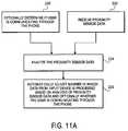
- FIG. 7CA method of operating a proximity sensor which includes the ability to both sense proximity and detect light is shown in FIG. 7C and an example, in block diagram form, of such a proximity sensor is shown in FIG. 7D .
- the method of FIG. 7Cmay use the proximity sensor shown in FIG. 7D or other proximity sensors.
- the methodincludes operation 135 in which electromagnetic radiation (e.g. IR light) is emitted from the emitter of the proximity sensor.
- the emittermay emit the radiation in a known, predetermined pattern (e.g. a train of square wave pulses of known, predetermined pulse width and frequency) which allows a detector to distinguish between ambient radiation and radiation from the emitter.
- the detector of the proximity sensordetects and measures light from the emitter when the detector is operating in proximity sensing mode.
- a processor coupled to the detectormay process the signal from the detector to identify the known predetermined pattern of radiation from the emitter and to measure the amount of radiation from the emitter.
- the detectoris used in a mode to sense radiation (e.g. ambient IR light) from a source other than the emitter; this operation may be implemented in a variety of ways.
- the emitted light from the emittermay be disabled by a shutter (either a mechanical or electrical shutter) placed over the emitter or the emitter's power source may be turned off (thereby stopping the emission of radiation from the emitter).
- known signal processing techniquesmay be used to remove the effect of the emitter's emitted light which is received at the detector in order to extract out the light from sources other than the emitter.
- FIG. 7Dshows an embodiment of a range sensing IR proximity sensor 145 which includes the ability to sense and measure proximity and to detect and measure ambient light levels.
- the proximity sensor 145includes an IR emitter 147 (e.g. an IR LED) and an IR detector 149 .
- An optional shuttere.g. an LCD electronic shutter
- the IR emitter 147 and the IR detector 149may be coupled to a microcontroller 151 which may control switching between proximity sensing mode and ambient light sensing mode by either closing and opening an optional shutter or by turning on and off the power to the IR emitter 147 .
- the output from the IR detector 149may be provided from the microcontroller 151 to the microprocessor 153 which determines, from data from the proximity sensor 145 , at least one proximity value and determines at least one ambient light level value.
- the microprocessormay be coupled to the IR emitter 147 and to the IR detector 149 without an intervening microcontroller, and the microprocessor may perform the functions of the microcontroller (e.g. the microprocessor may control switching between proximity sensing mode and ambient light sensing mode).
- the microprocessor 153may be coupled to other components 155 , such as input (e.g. keypad) or output (e.g. display) devices or memory devices or other sensors or a wireless transceiver system, etc.
- the microprocessor 153may be the main processor of the wireless device 100 shown in FIG. 6 .
- the microprocessor 153(or the microcontroller 151 ) may filter out the known predetermined pattern of IR light from the IR emitter 147 in order to extract a signal from the IR detector 149 representing the IR light level from sources other than the IR emitter 147 .
- the sensors which are used with embodiments of the inventionsmay determine or provide data which represents an analog value.
- the datarepresents a value which can be any one of a set of possible values which can vary continuously or substantially continuously, rather than being discrete values which have quantum, discrete jumps from one value to the next value.
- the value represented by the datamay not be predetermined. For example, in the case of a distance measured by a proximity sensor, the distance is not predetermined, unlike values of keys on a keypad which represent a predetermined value.
- a proximity sensormay determine or provide data that represents a distance which can vary continuously or nearly continuously in an analog fashion; in the case of such a proximity sensor, the distance may correspond to the intensity of reflected light which originated from the emitter of the proximity sensor.
- a temperature sensormay determine or provide data that represents a temperature, which is an analog value.
- a light sensorsuch as an ambient light sensor, may determine or provide data that represents a light intensity which is an analog value.
- a motion sensorsuch as an accelerometer, may determine or provide data which represents a measurement of motion (e.g. velocity or acceleration or both).
- a gyroscopemay determine or provide data which represents a measurement of orientation (e.g. amount of pitch or yaw or roll).
- a sound sensormay determine or provide data which represents a measurement of sound intensity. For other types of sensors, the data determined or provided by the sensor may represent an analog value.
- FIG. 8shows a diagram of various inputs from sensors that can be used and actions that can be performed in accordance with at least one embodiment of the invention.
- Any one of the devices described herein, including the devices shown in FIGS. 2 , 3 , 4 , 5 A and 5 B,may operate in accordance with the use of artificial intelligence as represented by FIG. 8 .
- One or more inputs on the left side of FIG. 8are received from various sensors of a device and are input into the artificial intelligence (AI) logic.
- One or more actions on the right side of FIG. 8may be implemented by the AI logic automatically in response to any combination of the inputs. In one implementation of this embodiment, the actions are implemented substantially immediately after the data is sensed by one or more sensors.
- Exemplary inputs of FIG. 8may include, for example, proximity data, proximity data and blob detect data (e.g., from a multipoint touch input screen), proximity data and accelerometer data, accelerometer data and blob detect data, proximity data and temperature data, proximity data and ambient light data, and numerous other possible combinations.
- proximity datae.g., from a multipoint touch input screen
- proximity data and accelerometer datae.g., from a multipoint touch input screen
- accelerometer data and blob detect datae.g., proximity data and temperature data
- proximity data and ambient light datae.g., ambient light data
- Exemplary actions of FIG. 8may include, for example, turning off the backlight of the portable device's display, suppressing the user's ability to input at the user interface (e.g., locking the input device), changing the telephone's mode, and the like. It will be appreciated that combinations of the above actions may also be implemented by the AI logic.
- the AI logicmay both turn off the display's backlight and suppress the user's ability to input at the user interface.
- the proximity data from a proximity sensormay be used to adjust the frequency response of the output of a receiver's amplifier section. This adjustment would allow the amplifier section to compensate for the variation of frequency response which occurs as a result of the variation of the distance between a speaker and a user's ear.
- This variationis caused by the variation of signal leakage introduced by a varying distance between the speaker and the user's ear. For example, when the ear is close (in close proximity) to the speaker, then the leak is low and the base response is better than when the ear is not as close to the speaker. When the speaker is farther removed from the ear, the degraded base response may be improved, in at least certain embodiments, by an equalizer which adjusts the base relative to the rest of the output signal in response to the distance, measured by the proximity sensor, between the user's ear and the speaker which provides the final output signal.
- AI logic of FIG. 8performs an AI (artificial intelligence) process.
- the AI processmay be performed without a specific, intentional user input or without user inputs having predetermined data associated therewith (e.g., key inputs).
- the artificial intelligence process performed by the AI logic of FIG. 8may use a variety of traditional AI logic processing, including pattern recognition and/or interpretation of data.
- the AI logicmay receive data from one or more sensors and compare the data to one or more threshold values and, based on those comparisons, determine how to interpret the data.
- a threshold valuemay represent a distance which is compared to a value derived from a light intensity measurement in a proximity sensor.
- a light intensity measurement which represents a distance larger than the threshold valueindicates that the object (which reflected the emitter's light) is not near, and a light intensity measurement which represents a distance smaller than the threshold value indicates that the object is near.
- the input datamay be subject to at least two interpretations (e.g. the data from a proximity sensor indicates that the user's head is near to the sensor, so turn off the back light, or the data from the proximity sensor indicates the user's head is not near, so leave the backlight under the control of a display timer), and the AI process attempts to select from the at least two interpretations to pick an interpretation that predicts a user activity.
- the AI logiccauses an action to be performed as indicated in FIG.
- the AI logicmay perform an AI process which interprets the data from one or more sensors (which interpretation requires the AI process to select between at least two possible interpretations) and which selects an action (e.g. modifying a setting of the device) based on both the interpretation of the sensor data and the current state of the device; the method shown in FIG. 11A is an example of the use of information about the current state of the device (e.g. whether the user is currently communicating through the telephone in the device) along with an interpretation of sensor data (proximity data in the case of FIG. 11A ).
- the AI processmay perform traditional methods of pattern recognition on the sensor data.
- the rate of change of the distance between the device and the user's earmay have a pattern (e.g. revealing a deceleration as the user moves the device closer to their ear), and this pattern in the rate of change of distance may be detected by a pattern matching algorithm.
- the phrase “artificial intelligence”is used throughout to mean that a conclusion (whether explicit or implicit) can be drawn from data available from one or more sensors about a mode of usage by the user of the device.
- a telephonemay be pre-programmed such that whenever it detects (1) a voice being spoken into the microphone, (2) that the phone is connected to a network, and (3) the proximity sensor is active, then the screen backlight will be dimmed.
- Such pre-programmingmay involve simple logic (e.g. simple combinatorial logic), but would nonetheless be within the scope of artificial intelligence as used herein. While learning, statistical analysis, iteration, and other complex aspects of AI can be used with the present invention, they are not required for the basic artificial intelligence contemplated.
- the word “analyze”does not imply sophisticated statistical or other analysis, but may involve observation of only a single threshold or datum.
- the AI processingmay be performed by a processor or processing system, such as digital processing system 103 , which is coupled to the one or more sensors that provide the data which form the inputs to the AI process. It will be appreciated that an AI process may be part of one or more of the methods shown in FIGS. 10 and 11 A- 11 F.
- the devicewhich operates according to any of those methods, may have at least one input device (e.g. a keypad or keyboard or touch input panel) which is designed to receive intentional user inputs (e.g. which specify a specific user entry) in addition to one or more sensors which are distinct and separate from the at least one input device and which sensors are not designed to receive intentional user inputs.
- at least one input devicee.g. a keypad or keyboard or touch input panel
- intentional user inputse.g. which specify a specific user entry
- sensorswhich are distinct and separate from the at least one input device and which sensors are not designed to receive intentional user inputs.
- a usermay not even be aware of the presence of the one or more sensors on the device.
- FIGS. 9A-Cillustrate exemplary user activities that can be determined based on input data acquired by the one or more sensors of the portable device.
- Exemplary user activitiesinclude, but are not limited to, the user looking directly at the portable device ( FIG. 9A ), the user holding the portable device at or near their ear ( FIG. 9B ), the user putting the portable device in a pocket or purse ( FIG. 9C ), and the like.
- FIG. 10is a flowchart illustrating a method 200 for automatically responding to certain user activities with respect to a portable device.
- method 200includes, but is not limited to, gathering sensor data designed to indicate user activity with respect to a portable device, and executing machine-executable code to perform one or more predetermined automated actions in response to the detection of the user activity.
- Operation 202gathers sensor data, from one or more sensors; the sensor data provides information about user activity.
- a proximity sensormay indicate whether the device is near the user's ear; a temperature sensor, an ambient light sensor (or a differential ambient light sensor) and a proximity sensor may together indicate that the device is in the user's pocket; a gyroscope and a proximity sensor may together indicate that the user is looking at the device.
- the data from the one or more sensorsis analyzed; this analysis may be performed by one or more processors within the device, including a processor within one or more of the sensors.
- the analysisattempts to predict user activity based on the sensor data. It will be appreciated that a prediction from this analysis may, in some cases, be wrong. For example, if a user places a finger over a proximity sensor when the user holds the device, this may cause the analysis to incorrectly conclude that the device is near the user's head or ear.
- one or more device settingsmay be adjusted based upon, at least in part, the analysis of the data from the one or more sensors. This adjusting may include changing an illumination setting of the device or other actions described herein.
- FIGS. 11A-Fillustrate exemplary methods for sensing data and automatically responding to the sensed data, and these methods may be performed by any one of the devices shown in FIGS. 2 , 3 , 4 , 5 A, 5 B, 6 and 12 and may or may not use the artificial intelligence process shown in FIG. 8 . It will be appreciated that several variations can be made to the illustrated methods, including variations to the data sensed, analysis of the data and the response(s) to the sensed data.
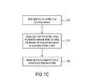
- the method of FIG. 11Aincludes optional operation 220 in which the device determines if the user is communicating through the telephone within the device. This may be performed by conventional techniques known in the art which can sense when a telephone call is in progress or when the user is otherwise communicating through the telephone or other communication device.
- proximity sensor datais received from one or more proximity sensors on the device.
- the proximity sensor datais analyzed. For example, the data is analyzed to determine whether an object, such as the user's ear or head, is near the device. This analysis is used to decide whether and how to adjust the device's settings as shown in operation 226 .
- One or more settings of the devicemay be automatically adjusted based on the analysis of the proximity sensor data and optionally based on whether or not the user is communicating through the telephone or other communication device. For example, if the proximity sensor indicates that the device is near the user's head or ear and it has been determined that the user is communicating through the telephone, then the device determines that the user is talking or otherwise communicating on the telephone or other communication device by having the device next to the user's ear as shown in FIG. 9B . In this situation, the device automatically changes the manner in which data from one or more input devices is processed, such as suppressing a user's ability to make intentional inputs on an input device, such as a keypad or a touch input panel on the device.
- the devicemay automatically adjust a power setting of one or more displays of the device. If, on the other hand, the device determines that the user is not communicating though the telephone while the proximity sensor data indicates that an object is near to the device, the device may decide not to modify an illumination setting of the display and to not suppress the user's ability to enter intentional user inputs on an input device.
- the suppressing of inputsmay occur in one of a variety of ways, for example, inputs may be suppressed by turning off or reducing power to the input device such that it is not operational while in this mode; in another example, inputs may be suppressed while in this mode by not processing any inputs which are received by a fully powered input device; in yet another example, inputs are not processed as intentional inputs but are processed to confirm they are “blobs” resulting from touches or near touches on the input device. In the last example, even though an input appears to be an activation of a key (the “3” button on a keypad) or other user interface item, the input is not processed as an activation of that key but rather is processed to determine whether it is a “blob.”
- FIG. 11Bshows a method of an embodiment of the present inventions which relates to a technique for controlling when data from an input device is processed as an input and when it is ignored as an intentional user input.
- the devicereceives movement data from one or more sensors.
- sensorsmay include an accelerometer or a motion sensor or other types of sensors which indicate movement data.
- These sensorsmay be designed to distinguish between rapid movements and slow movements. This is particularly true if the movements involve high levels of acceleration. It is assumed in this embodiment that rapid movements may be so rapid that it is unlikely the user could be intending to enter a user input and hence the device may decide to ignore inputs which occur when such sensors indicate that the movement is faster than a threshold movement value.
- the movement datais analyzed in operation 232 to determine whether or not to automatically suppress a user's ability to input key inputs or other inputs based on the device's movement.
- the devicemay automatically suppress a user's ability to enter inputs on an input device in response to the analysis in operation 232 .
- FIG. 11Crelates to an embodiment of the present inventions in which data relating to a location of the device and data relating to movement of the device are analyzed to determine whether or not to adjust one or more settings of the device.
- data relating to the location of the deviceis received; this data may, for example, be provided by a proximity sensor.
- data relating to device movementis also received. This data may be from a motion sensor or from an accelerometer.
- the data relating to location and the data relating to device movementare analyzed to determine whether or not to adjust a setting of the device. This analysis may be performed in a variety of different ways.
- the data relating to device motionmay show a pattern of movement which matches the movement which occurs when a user moves the device from the user's pocket to the user's head.
- the analysismay further determine that the proximity data or other data relating to location showed that the device was not near the user's head or another object until near the end of the movement. In such a situation, the analysis would determine that the user has pulled the device from their pocket and placed it against the user's ear.
- one or more settings of the deviceare adjusted automatically, without any intentional user input, based upon the analysis. For example, an adjustment may be made in the manner in which data from an input device, such as a touch input panel, is processed.
- a display's illumination settingmay be adjusted. For example, if the analysis of operation 264 determines the user has moved the device from a location away from the ear to a location close to the ear then, in one embodiment, an illumination setting may be adjusted and the user's ability to enter intentional inputs into an input device may be suppressed.
- FIG. 11Dshows an embodiment of the present inventions in which data relating to location and data relating to temperature is processed through an analysis to determine whether or not to adjust one or more device settings of the device.
- data relating to locationsuch as data from a proximity sensor
- data relating to temperaturesuch as temperature data or temperature differential data
- the data relating to location and the data relating to temperatureare analyzed to determine whether to adjust one or more settings of the device.
- one or more device settingsare adjusted in response to the analysis of operation 274 .
- FIG. 11Eshows an embodiment of the present inventions in which data relating to location of a device and data relating to touches on a touch input panel of the device are analyzed to determine whether to adjust a setting of the device.
- data relating to location of the deviceis received in operation 290 and data relating to touches on a touch input panel is received in operation 292 .
- the data relating to locationmay be from a proximity sensor.
- the data relating to touches on a touch input panelmay be from a multi-point touch input panel which is capable of detecting multiple point touches which may occur when a user's face is pressed against or is otherwise near the touch input panel.
- the data relating to location and the data relating to touchesare analyzed to determine whether to adjust a setting of the device.
- one or more device settingsare adjusted.
- the adjustmentmay include automatically reducing power to the backlight of a display or changing the manner in which data from the touch input panel is processed, or both adjustments.
- a mode of the devicemay be used in order to determine whether to or how to adjust a setting of the device.
- the mode of the devicemay include any one of a variety of modes or conditions, such as speakerphone mode or non-speakerphone mode, battery powered mode or not battery powered mode, call waiting mode or not call waiting mode, an alert mode in which the device may make a sound, such as the sound of an alarm, etc.
- the data relating to user activitye.g. data from one or more sensors, such as a proximity sensor and/or a touch input panel, which is capable of detecting blobs from a face
- the analysisattempts to determine whether to adjust a setting of the device.
- One or more device settingsmay be adjusted based on the sensed user activity and the device mode. For example, the device may automatically switch from speakerphone mode to non-speakerphone mode when proximity data, and optionally other data (e.g. data from a motion sensor and an ambient light sensor) indicate the user has placed the device, which in this case may be a telephone, next to the user's ear. In this example, the device has automatically switched from speakerphone mode to non-speakerphone mode without any intentional input from the user which indicates that the switch should occur. Another method involves adjusting an alert or alarm volume depending on whether or not the device is near to the user's ear.
- proximity datae.g. data from a motion sensor and an ambient light sensor
- the devicewill automatically change the volume level for an alert or an alarm from a first level to a second level which is not as loud as the first level.
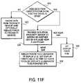
- FIG. 11Fshows an embodiment of the inventions in which data from a device configuration detector, such as a hinge detector, is used to determine how to process data from one or more sensors on the device.
- this method shown in FIG. 11Fmay be used with the device shown in FIGS. 5A and 5B (and the proximity sensor referred to in FIG. 11F may be proximity sensor 84 in FIG. 5A ).
- a hinge detectorwhich is coupled to the hinge 87 may detect whether the device is open as shown in FIG. 5A or closed as shown in FIG. 5B .
- Other configuration detectorsmay indicate whether a slide out input device (e.g. a slide out keyboard) or other type of input device has been pulled out (or swung out) or not from a portion of the device.
- the devicedetermines whether data from a hinge detector shows that the device is open. If the device is not open, then in operation 322 , data from a proximity sensor is ignored if the proximity sensor is disposed on an interior surface of the device. Optionally, the power to the proximity sensor may be reduced by, for example, turning off the proximity sensor when the device is in a closed state. If it is determined in operation 320 that the device is open, then in operation 324 , data from the proximity sensor is processed to determine whether the device is placed near an object, such as the user's ear.
- a display timerwhich controls the time that the display is illuminated, is allowed to continue to run in operation 326 .
- This display timermay be similar to a conventional display timer which begins counting down to a time out state in response to activating a backlight of a display. The display timer counts down to a time out state and, if no input resets the timer to its starting value while it counts down, then the timer reaches its time out state and causes, in response to the time out state, the display's backlight to be powered off (or otherwise have its power consumption state reduced).
- operation 328power to an illuminator of the display is reduced. This may be performed by setting the display timer's value to a time out state to thereby cause the display's illuminator to be powered off. It will be appreciated that the method of FIG. 11F may save additional battery life by reducing power to the illuminator of the display before the display timer runs out.
- a method which uses a display timermay be used in addition to at least certain embodiments of the inventions which adjust illumination settings.
- a display timer which has been startedmay continue to count while the method shown in FIG. 11A is performed.
- the display timerwill count, while the method of FIG. 11A is being performed, until its time out state is reached and, upon doing so, the display timer may cause the illumination setting to be changed before the method of FIG. 11A is completed.
- the illumination settingis controlled by both the display timer and one or more sensors of at least certain embodiments of the inventions which cause an adjusting of illumination settings based upon the analysis of data from one or more sensors.
- proximity sensoris used throughout to mean a sensor, such as a capacitive, temperature, inductive, infrared or other variety of sensor, which is capable of detecting whether an object is present within a certain distance of the sensor.
- a primary object of this detectingmay be the head of the user (or any other object that would present viewing of the display screen).
- any of the embodiments of the inventionsmay include one or more user interface controls which allow a user to override a result caused by one or more sensors.
- a controlsuch as a button
- the user interface controlmay be a sensor (or group of sensors), such as an accelerometer, which detects a user interaction with the device (e.g. shaking the device), and the user interaction has been set up to cause an overriding of a state caused by one or more sensors.
- Certain embodiments of the inventionsmay employ one or more light sensors which provide data relating to light, which data is analyzed to determine whether or not to adjust one or more settings of a device, such as wireless device 100 .
- Ambient light level datamay be provided by an ambient light sensor which indicates the level of light intensity surrounding that sensor.
- Ambient light differential datamay be obtained from two or more ambient light sensors which are disposed at different positions on the device. For example, one ambient light sensor may be on one side of the device, and another ambient light sensor may be on another side of the device. A different in the light intensity levels may be determined by comparing the data from these two ambient light sensors on two different sides or surfaces of the device. There are a variety of possible uses of a light sensor.
- a light sensormay be used with a proximity sensor to determine when a device is placed in a pocket to cause the device to be set in vibrate mode only or vibrate mode with audible ringing.
- the devicein response to a light sensor determining that the ambient light is very low, and optionally in response to a user having set the device to visibly light up to show an incoming call when the ambient light is very low, the device may automatically be put in a “light ring” mode when it is dark so that instead of an audible ring from the device, the display flashes visibly (e.g. by repeatedly turning on and off the backlight) to indicate an incoming call.
- a light sensorAnother exemplary use of a light sensor involves using it as an alarm indicating that a dark room (or environment) has become brighter (e.g. the sun has risen or a door to a darkened room is opened to let light into the room).
- a light sensormay also be used to cause a device to automatically act as a source of light (e.g. as a flashlight, in effect) upon sensing a low ambient light level.
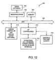
- FIG. 12shows another example of a device according to an embodiment of the inventions.
- This devicemay include a processor, such as microprocessor 402 , and a memory 404 , which are coupled to each other through a bus 406 .
- the device 400may optionally include a cache 408 which is coupled to the microprocessor 402 .
- This devicemay also optionally include a display controller and display device 410 which is coupled to the other components through the bus 406 .
- One or more input/output controllers 412are also coupled to the bus 406 to provide an interface for input/output devices 414 and to provide an interface for one or more sensors 416 which are for sensing user activity.
- the bus 406may include one or more buses connected to each other through various bridges, controllers, and/or adapters as is well known in the art.
- the input/output devices 414may include a keypad or keyboard or a cursor control device such as a touch input panel.
- the input/output devices 414may include a network interface which is either for a wired network or a wireless network (e.g. an RF transceiver).
- the sensors 416may be any one of the sensors described herein including, for example, a proximity sensor or an ambient light sensor.
- the microprocessor 402may receive data from one or more sensors 416 and may perform the analysis of that data in the manner described herein. For example, the data may be analyzed through an artificial intelligence process or in the other ways described herein. As a result of that analysis, the microprocessor 402 may then automatically cause an adjustment in one or more settings of the device.
Landscapes
- Engineering & Computer Science (AREA)
- Signal Processing (AREA)
- Human Computer Interaction (AREA)
- Computer Networks & Wireless Communication (AREA)
- Theoretical Computer Science (AREA)
- General Engineering & Computer Science (AREA)
- Physics & Mathematics (AREA)
- General Physics & Mathematics (AREA)
- Environmental & Geological Engineering (AREA)
- Telephone Function (AREA)
- User Interface Of Digital Computer (AREA)
- Inspection Of Paper Currency And Valuable Securities (AREA)
- Photometry And Measurement Of Optical Pulse Characteristics (AREA)
- Geophysics And Detection Of Objects (AREA)
Abstract
Description
Claims (52)
Priority Applications (8)
| Application Number | Priority Date | Filing Date | Title |
|---|---|---|---|
| US11/600,344US7728316B2 (en) | 2005-09-30 | 2006-11-15 | Integrated proximity sensor and light sensor |
| US11/650,117US7714265B2 (en) | 2005-09-30 | 2007-01-05 | Integrated proximity sensor and light sensor |
| CN200780042471.7ACN101558372B (en) | 2006-11-15 | 2007-11-01 | Integrated proximity sensor and light sensor |
| HK10100865.0AHK1137240B (en) | 2006-11-15 | 2007-11-01 | Integrated proximity sensor and light sensor |
| PCT/US2007/023124WO2008066645A2 (en) | 2006-11-15 | 2007-11-01 | Integrated proximity sensor and light sensor |
| EP07870833.6AEP2082313B1 (en) | 2006-11-15 | 2007-11-01 | Integrated proximity sensor and light sensor |
| US12/750,625US8536507B2 (en) | 2005-09-30 | 2010-03-30 | Integrated proximity sensor and light sensor |
| US14/010,244US8829414B2 (en) | 2005-09-30 | 2013-08-26 | Integrated proximity sensor and light sensor |
Applications Claiming Priority (2)
| Application Number | Priority Date | Filing Date | Title |
|---|---|---|---|
| US11/241,839US7653883B2 (en) | 2004-07-30 | 2005-09-30 | Proximity detector in handheld device |
| US11/600,344US7728316B2 (en) | 2005-09-30 | 2006-11-15 | Integrated proximity sensor and light sensor |
Related Parent Applications (1)
| Application Number | Title | Priority Date | Filing Date |
|---|---|---|---|
| US11/241,839Continuation-In-PartUS7653883B2 (en) | 2004-07-30 | 2005-09-30 | Proximity detector in handheld device |
Related Child Applications (2)
| Application Number | Title | Priority Date | Filing Date |
|---|---|---|---|
| US11/240,788Continuation-In-PartUS8381135B2 (en) | 2004-07-30 | 2005-09-30 | Proximity detector in handheld device |
| US11/650,117Continuation-In-PartUS7714265B2 (en) | 2005-09-30 | 2007-01-05 | Integrated proximity sensor and light sensor |
Publications (2)
| Publication Number | Publication Date |
|---|---|
| US20070085157A1 US20070085157A1 (en) | 2007-04-19 |
| US7728316B2true US7728316B2 (en) | 2010-06-01 |
Family
ID=39273114
Family Applications (1)
| Application Number | Title | Priority Date | Filing Date |
|---|---|---|---|
| US11/600,344Expired - LifetimeUS7728316B2 (en) | 2005-09-30 | 2006-11-15 | Integrated proximity sensor and light sensor |
Country Status (4)
| Country | Link |
|---|---|
| US (1) | US7728316B2 (en) |
| EP (1) | EP2082313B1 (en) |
| CN (1) | CN101558372B (en) |
| WO (1) | WO2008066645A2 (en) |
Cited By (44)
| Publication number | Priority date | Publication date | Assignee | Title |
|---|---|---|---|---|
| US20090066533A1 (en)* | 2007-09-06 | 2009-03-12 | Microinfinity, Inc. | Control apparatus and method |
| US20090121889A1 (en)* | 2007-11-14 | 2009-05-14 | Intersil Americas Inc. | Proximity sensors and methods for sensing proximity |
| US20100072351A1 (en)* | 2008-09-25 | 2010-03-25 | Apple Inc. | Ambient light sensor with reduced sensitivity to noise from infrared sources |
| US20100277075A1 (en)* | 2009-04-29 | 2010-11-04 | Intersil Americas Inc. | Long range proximity and/or motion detector with ambient light detection capabilities |
| US20110133941A1 (en)* | 2009-12-04 | 2011-06-09 | Avago Technologies Ecbu (Singapore) Pte. Ltd. | Optical Proximity Sensor with Improved Shield and Lenses |
| US20110312286A1 (en)* | 2010-06-17 | 2011-12-22 | Rfmarq, Inc. | Activating Dormant Wireless Circuitry Using Motion or Incident Light |
| US20120042257A1 (en)* | 2010-08-11 | 2012-02-16 | Microsoft Corporation | Updating application data after anticipating imminent use |
| US8170621B1 (en) | 2011-02-16 | 2012-05-01 | Google Inc. | Mobile device display management |
| US20120188543A1 (en)* | 2011-01-25 | 2012-07-26 | Seong-Bo Shim | Method and apparatus for measuring overlay |
| US20130120761A1 (en)* | 2011-11-11 | 2013-05-16 | Intersil Americas LLC | Optical proximity sensors with offset compensation |
| US20130215070A1 (en)* | 2011-10-24 | 2013-08-22 | Yamaha Corporation | Electronic acoustic signal generating device and electronic acoustic signal generating method |
| US20130278576A1 (en)* | 2012-04-18 | 2013-10-24 | Apple Inc. | Calibrated image-sensor-based ambient light sensor |
| US20140085201A1 (en)* | 2012-09-21 | 2014-03-27 | Research In Motion Limited | Device with touch screen false actuation prevention |
| US8829414B2 (en) | 2005-09-30 | 2014-09-09 | Apple Inc. | Integrated proximity sensor and light sensor |
| US20140292658A1 (en)* | 2013-03-27 | 2014-10-02 | Research In Motion Limited | Keypad with optical sensors |
| US8958786B2 (en) | 2013-05-23 | 2015-02-17 | Elwha Llc | Mobile device that activates upon removal from storage |
| US8971572B1 (en) | 2011-08-12 | 2015-03-03 | The Research Foundation For The State University Of New York | Hand pointing estimation for human computer interaction |
| US8971869B2 (en) | 2013-05-23 | 2015-03-03 | Elwha Llc | Mobile device that activates upon removal from storage |
| US8994926B2 (en) | 2012-02-14 | 2015-03-31 | Intersil Americas LLC | Optical proximity sensors using echo cancellation techniques to detect one or more objects |
| US9046415B2 (en) | 2012-09-11 | 2015-06-02 | Apple Inc. | Virtual detector for sensor system |
| US9065929B2 (en) | 2011-08-02 | 2015-06-23 | Apple Inc. | Hearing aid detection |
| US9077884B2 (en) | 2012-03-21 | 2015-07-07 | Htc Corporation | Electronic devices with motion response and related methods |
| US9122451B2 (en) | 2013-09-30 | 2015-09-01 | Sonos, Inc. | Capacitive proximity sensor configuration including a speaker grille |
| US9143704B2 (en) | 2012-01-20 | 2015-09-22 | Htc Corporation | Image capturing device and method thereof |
| US9223353B2 (en) | 2013-09-30 | 2015-12-29 | Sonos, Inc. | Ambient light proximity sensing configuration |
| US9225307B2 (en) | 2012-06-28 | 2015-12-29 | Sonos, Inc. | Modification of audio responsive to proximity detection |
| US9280266B2 (en) | 2010-11-12 | 2016-03-08 | Kt Corporation | Apparatus and method for displaying information as background of user interface |
| US9285886B2 (en) | 2013-06-24 | 2016-03-15 | Sonos, Inc. | Intelligent amplifier activation |
| US9291495B2 (en) | 2013-03-06 | 2016-03-22 | Apple Inc. | Proximity sensor with combined light sensor having an increased viewing angle |
| US9323404B2 (en) | 2013-09-30 | 2016-04-26 | Sonos, Inc. | Capacitive proximity sensor configuration including an antenna ground plane |
| US9542046B2 (en) | 2013-06-26 | 2017-01-10 | Atmel Corporation | Changing the detection range of a touch sensor |
| US20170285868A1 (en)* | 2014-08-29 | 2017-10-05 | Huawei Technologies Co., Ltd. | Method and apparatus for preventing touchscreen misoperation |
| US9788277B2 (en) | 2015-01-15 | 2017-10-10 | Mediatek Inc. | Power saving mechanism for in-pocket detection |
| US9927915B2 (en) | 2014-09-26 | 2018-03-27 | Cypress Semiconductor Corporation | Optical navigation systems and methods for background light detection and avoiding false detection and auto-movement |
| US9976894B2 (en) | 2015-11-17 | 2018-05-22 | Heptagon Micro Optics Pte. Ltd. | Optical device |
| US20190035238A1 (en)* | 2014-12-16 | 2019-01-31 | Amazon Technologies, Inc. | Activation of security mechanisms through accelerometer-based dead reckoning |
| WO2019035843A1 (en)* | 2017-08-18 | 2019-02-21 | Hewlett-Packard Development Company, L.P. | Motion based power states |
| US10551987B2 (en) | 2011-05-11 | 2020-02-04 | Kt Corporation | Multiple screen mode in mobile terminal |
| US10582144B2 (en) | 2009-05-21 | 2020-03-03 | May Patents Ltd. | System and method for control based on face or hand gesture detection |
| WO2020185446A1 (en) | 2019-03-08 | 2020-09-17 | Array Photonics, Inc. | Electronic devices having displays with infrared components behind the displays |
| US11112872B2 (en)* | 2011-04-13 | 2021-09-07 | Nokia Technologies Oy | Method, apparatus and computer program for user control of a state of an apparatus |
| US11249798B1 (en) | 2020-09-16 | 2022-02-15 | International Business Machines Corporation | Personalized timeout control |
| US11326939B2 (en)* | 2017-11-03 | 2022-05-10 | Samsung Electronics Co., Ltd | Electronic device for measuring illuminance, and operating method therefor |
| US11606455B2 (en) | 2018-07-17 | 2023-03-14 | Honor Device Co., Ltd. | Method for preventing mistouch by using top-emitted proximity light, and terminal |
Families Citing this family (140)
| Publication number | Priority date | Publication date | Assignee | Title |
|---|---|---|---|---|
| US8952895B2 (en)* | 2011-06-03 | 2015-02-10 | Apple Inc. | Motion-based device operations |
| US8381135B2 (en) | 2004-07-30 | 2013-02-19 | Apple Inc. | Proximity detector in handheld device |
| US7728316B2 (en) | 2005-09-30 | 2010-06-01 | Apple Inc. | Integrated proximity sensor and light sensor |
| US7633076B2 (en) | 2005-09-30 | 2009-12-15 | Apple Inc. | Automated response to and sensing of user activity in portable devices |
| US8144115B2 (en) | 2006-03-17 | 2012-03-27 | Konicek Jeffrey C | Flat panel display screen operable for touch position determination system and methods |
| US7859526B2 (en)* | 2006-05-01 | 2010-12-28 | Konicek Jeffrey C | Active matrix emissive display and optical scanner system, methods and applications |
| US8006002B2 (en) | 2006-12-12 | 2011-08-23 | Apple Inc. | Methods and systems for automatic configuration of peripherals |
| US8698727B2 (en)* | 2007-01-05 | 2014-04-15 | Apple Inc. | Backlight and ambient light sensor system |
| US8031164B2 (en)* | 2007-01-05 | 2011-10-04 | Apple Inc. | Backlight and ambient light sensor system |
| US7957762B2 (en)* | 2007-01-07 | 2011-06-07 | Apple Inc. | Using ambient light sensor to augment proximity sensor output |
| US8693877B2 (en)* | 2007-03-09 | 2014-04-08 | Apple Inc. | Integrated infrared receiver and emitter for multiple functionalities |
| US9954996B2 (en) | 2007-06-28 | 2018-04-24 | Apple Inc. | Portable electronic device with conversation management for incoming instant messages |
| US8125619B2 (en)* | 2007-07-25 | 2012-02-28 | Eminent Electronic Technology Corp. | Integrated ambient light sensor and distance sensor |
| CN101779184A (en)* | 2007-08-13 | 2010-07-14 | 日本电气株式会社 | Contact type input device, contact type input method, and program |
| US9414804B2 (en)* | 2007-08-24 | 2016-08-16 | General Electric Company | Diagnostic imaging device having protective facade and method of cleaning and disinfecting same |
| CN105072285A (en) | 2007-12-27 | 2015-11-18 | 日本电气株式会社 | Mobile phone terminal |
| US20090209285A1 (en)* | 2008-02-15 | 2009-08-20 | Sony Ericsson Mobile Communications Ab | Portable communication device having touch-sensitive input device ... |
| US8174483B2 (en)* | 2008-02-20 | 2012-05-08 | Computime, Ltd. | Automatic display unit activation |
| US8174489B2 (en)* | 2008-03-05 | 2012-05-08 | Sony Mobile Communications Ab | Dual-sided display for mobile device |
| US20100163713A1 (en)* | 2008-03-10 | 2010-07-01 | Lite-On Semiconductor Corp. | Electromagnetic wave sensing apparatus |
| US20090225306A1 (en)* | 2008-03-10 | 2009-09-10 | Chia-Chu Cheng | Electromagnetic wave sensing apparatus |
| US20100039214A1 (en)* | 2008-08-15 | 2010-02-18 | At&T Intellectual Property I, L.P. | Cellphone display time-out based on skin contact |
| US8913991B2 (en)* | 2008-08-15 | 2014-12-16 | At&T Intellectual Property I, L.P. | User identification in cell phones based on skin contact |
| EP2159997A1 (en)* | 2008-09-02 | 2010-03-03 | Research In Motion Limited | Dual light sensors on a portable electronic device |
| WO2010047807A1 (en) | 2008-10-22 | 2010-04-29 | Tom Chang | Light detection circuit for ambient light and proximity sensor |
| US9058066B2 (en)* | 2008-11-12 | 2015-06-16 | Apple Inc. | Suppressing errant motion using integrated mouse and touch information |
| US20100181467A1 (en)* | 2009-01-20 | 2010-07-22 | Tom Chang | Light-Proximity-Inertial Sensor Combination |
| JP4829991B2 (en)* | 2009-03-23 | 2011-12-07 | シャープ株式会社 | Automatic dimming system |
| US8420999B2 (en)* | 2009-05-08 | 2013-04-16 | Avago Technologies Ecbu Ip (Singapore) Pte. Ltd. | Metal shield and housing for optical proximity sensor with increased resistance to mechanical deformation |
| WO2010134899A1 (en)* | 2009-05-20 | 2010-11-25 | Tom Chang | Optical touch panel |
| US9398536B2 (en)* | 2009-05-29 | 2016-07-19 | Qualcomm Incorporated | Method and apparatus for movement detection by evaluating elementary movement patterns |
| WO2010145031A1 (en)* | 2009-06-19 | 2010-12-23 | Research In Motion Limited | Portable electronic device with face touch detection |
| US8957380B2 (en)* | 2009-06-30 | 2015-02-17 | Avago Technologies General Ip (Singapore) Pte. Ltd. | Infrared attenuating or blocking layer in optical proximity sensor |
| US9525093B2 (en) | 2009-06-30 | 2016-12-20 | Avago Technologies General Ip (Singapore) Pte. Ltd. | Infrared attenuating or blocking layer in optical proximity sensor |
| US8779361B2 (en)* | 2009-06-30 | 2014-07-15 | Avago Technologies General Ip (Singapore) Pte. Ltd. | Optical proximity sensor package with molded infrared light rejection barrier and infrared pass components |
| US8716665B2 (en)* | 2009-09-10 | 2014-05-06 | Avago Technologies General Ip (Singapore) Pte. Ltd. | Compact optical proximity sensor with ball grid array and windowed substrate |
| JP2011065488A (en)* | 2009-09-17 | 2011-03-31 | Sony Corp | Information processing apparatus, data acquisition method and program |
| US9733357B2 (en)* | 2009-11-23 | 2017-08-15 | Avago Technologies General Ip (Singapore) Pte. Ltd. | Infrared proximity sensor package with improved crosstalk isolation |
| US9185488B2 (en)* | 2009-11-30 | 2015-11-10 | Nokia Technologies Oy | Control parameter dependent audio signal processing |
| US8531414B2 (en)* | 2010-02-03 | 2013-09-10 | Bump Technologies, Inc. | Bump suppression |
| US8981913B2 (en)* | 2010-02-18 | 2015-03-17 | Redwood Systems, Inc. | Commissioning lighting systems |
| US9572228B2 (en) | 2010-02-18 | 2017-02-14 | Redwood Systems, Inc. | Commissioning lighting systems |
| US8706271B2 (en)* | 2010-02-18 | 2014-04-22 | Redwood Systems, Inc. | Integration of computing device and lighting system |
| US20110205164A1 (en)* | 2010-02-23 | 2011-08-25 | Gm Global Technology Operations, Inc. | Method of changing the state of an electronic device |
| US20110223974A1 (en)* | 2010-03-10 | 2011-09-15 | Sony Ericsson Mobile Communications Ab | Mobile communication device and method for operating a mobile communication device |
| KR20110117907A (en)* | 2010-04-22 | 2011-10-28 | 삼성전자주식회사 | Proximity sensing method and apparatus for mobile terminal |
| US20110294470A1 (en)* | 2010-05-26 | 2011-12-01 | Research In Motion Limited | Method and apparatus for detecting and amplifying notification signals |
| US20110300901A1 (en)* | 2010-06-02 | 2011-12-08 | Microsoft Corporation | Intelligent Input Handling |
| CN101893994A (en)* | 2010-07-14 | 2010-11-24 | 中兴通讯股份有限公司 | Intelligent screen lock method and terminal |
| US20120032894A1 (en) | 2010-08-06 | 2012-02-09 | Nima Parivar | Intelligent management for an electronic device |
| TWI433017B (en)* | 2010-08-19 | 2014-04-01 | Htc Corp | Electronic device and control method thereof |
| US8643481B2 (en)* | 2010-09-17 | 2014-02-04 | Johnson Controls Technology Company | Interior rearview mirror assembly with integrated indicator symbol |
| US9180819B2 (en)* | 2010-09-17 | 2015-11-10 | Gentex Corporation | Interior rearview mirror assembly with integrated indicator symbol |
| US9077365B2 (en) | 2010-10-15 | 2015-07-07 | S.C. Johnson & Son, Inc. | Application specific integrated circuit including a motion detection system |
| CN102572073A (en)* | 2010-12-17 | 2012-07-11 | 沈阳新邮通信设备有限公司 | Mobile communication terminal capable of detecting object moving direction |
| FR2971066B1 (en) | 2011-01-31 | 2013-08-23 | Nanotec Solution | THREE-DIMENSIONAL MAN-MACHINE INTERFACE. |
| US8618482B2 (en)* | 2011-02-22 | 2013-12-31 | Blackberry Limited | Mobile device with proximity sensor |
| US10146329B2 (en)* | 2011-02-25 | 2018-12-04 | Nokia Technologies Oy | Method and apparatus for providing different user interface effects for different motion gestures and motion properties |
| US8937735B2 (en)* | 2011-03-31 | 2015-01-20 | Brother Kogyo Kabushiki Kaisha | Non-transitory storage medium storing image-forming-data transmitting program, mobile terminal, and control method therefor transmitting movement and orientation information of mobile terminal |
| US9366749B2 (en) | 2011-04-15 | 2016-06-14 | Qualcomm Incorporated | Device position estimates from motion and ambient light classifiers |
| CN102759991A (en)* | 2011-04-28 | 2012-10-31 | 宏达国际电子股份有限公司 | Electronic device and related control method thereof |
| US9391568B2 (en)* | 2011-05-16 | 2016-07-12 | Rosemount Inc. | Process device with light change triggered display |
| US10715380B2 (en) | 2011-05-23 | 2020-07-14 | Apple Inc. | Setting a reminder that is triggered by a target user device |
| US8971924B2 (en) | 2011-05-23 | 2015-03-03 | Apple Inc. | Identifying and locating users on a mobile network |
| ES2530019T3 (en) | 2011-05-24 | 2015-02-25 | Huawei Device Co., Ltd. | Method and apparatus for reducing power consumption of mobile phone and mobile phone |
| CN102301684B (en)* | 2011-06-24 | 2014-01-22 | 华为终端有限公司 | Method and device for a terminal to determine approach of an object |
| US9411442B2 (en) | 2011-06-29 | 2016-08-09 | Google Technology Holdings LLC | Electronic device having managed input components |
| US8890823B2 (en)* | 2012-01-09 | 2014-11-18 | Motorola Mobility Llc | System and method for reducing occurrences of unintended operations in an electronic device |
| JP5914824B2 (en)* | 2011-07-05 | 2016-05-11 | パナソニックIpマネジメント株式会社 | Imaging device |
| US8826188B2 (en)* | 2011-08-26 | 2014-09-02 | Qualcomm Incorporated | Proximity sensor calibration |
| US8723824B2 (en) | 2011-09-27 | 2014-05-13 | Apple Inc. | Electronic devices with sidewall displays |
| KR102027601B1 (en) | 2011-10-18 | 2019-10-01 | 카네기 멜론 유니버시티 | Method and apparatus for classifying touch events on a touch sensitive surface |
| US20120092248A1 (en)* | 2011-12-23 | 2012-04-19 | Sasanka Prabhala | method, apparatus, and system for energy efficiency and energy conservation including dynamic user interface based on viewing conditions |
| US8766162B2 (en)* | 2012-01-12 | 2014-07-01 | Maxim Integrated Products, Inc. | Ambient light based gesture detection |
| CN103309481B (en)* | 2012-03-08 | 2016-05-04 | 群康科技(深圳)有限公司 | Display module and electronic installation |
| CN104303520B (en)* | 2012-03-16 | 2018-09-14 | 诺基亚技术有限公司 | Devices for audio transducers |
| US20130257583A1 (en)* | 2012-03-29 | 2013-10-03 | Motorola Mobility, Inc. | Wireless communication device and method with ultrasonic detection |
| EP2645684A1 (en)* | 2012-03-30 | 2013-10-02 | BlackBerry Limited | Apparatus, and associated method, for controlling volumetric output level of a handset receiver |
| KR20130120599A (en)* | 2012-04-26 | 2013-11-05 | 엘지전자 주식회사 | Mobile terminal and control method thereof |
| US9330606B2 (en)* | 2012-06-08 | 2016-05-03 | Apple Inc. | Electronic device with display brightness control |
| US9445174B2 (en)* | 2012-06-14 | 2016-09-13 | Nokia Technologies Oy | Audio capture apparatus |
| US9648409B2 (en)* | 2012-07-12 | 2017-05-09 | Apple Inc. | Earphones with ear presence sensors |
| CN102841684B (en)* | 2012-08-30 | 2015-12-16 | 小米科技有限责任公司 | A kind of method, device and equipment preventing maloperation |
| US9411048B2 (en)* | 2012-08-30 | 2016-08-09 | Apple Inc. | Electronic device with adaptive proximity sensor threshold |
| US9146304B2 (en) | 2012-09-10 | 2015-09-29 | Apple Inc. | Optical proximity sensor with ambient light and temperature compensation |
| EP2711824B1 (en)* | 2012-09-21 | 2019-07-31 | BlackBerry Limited | A device with touch screen false-actuation prevention |
| CN103167151A (en)* | 2012-09-21 | 2013-06-19 | 深圳市金立通信设备有限公司 | Automatic screen-locking system and method for mobile phone placed in pocket |
| CN103941994A (en)* | 2013-01-23 | 2014-07-23 | 中兴通讯股份有限公司 | Sensing screen locking method and device of touch screen |
| US8989773B2 (en) | 2013-01-29 | 2015-03-24 | Apple Inc. | Sharing location information among devices |
| FR3002052B1 (en) | 2013-02-14 | 2016-12-09 | Fogale Nanotech | METHOD AND DEVICE FOR NAVIGATING A DISPLAY SCREEN AND APPARATUS COMPRISING SUCH A NAVIGATION |
| US10134267B2 (en) | 2013-02-22 | 2018-11-20 | Universal City Studios Llc | System and method for tracking a passive wand and actuating an effect based on a detected wand path |
| US11044451B2 (en)* | 2013-03-14 | 2021-06-22 | Jawb Acquisition Llc | Proximity-based control of media devices for media presentations |
| KR20140114766A (en) | 2013-03-19 | 2014-09-29 | 퀵소 코 | Method and device for sensing touch inputs |
| US9612689B2 (en) | 2015-02-02 | 2017-04-04 | Qeexo, Co. | Method and apparatus for classifying a touch event on a touchscreen as related to one of multiple function generating interaction layers and activating a function in the selected interaction layer |
| US9013452B2 (en) | 2013-03-25 | 2015-04-21 | Qeexo, Co. | Method and system for activating different interactive functions using different types of finger contacts |
| CN104102337A (en)* | 2013-04-08 | 2014-10-15 | 普雷森株式会社 | Method and apparatus for determining proximity level between user and electronic device |
| US9345098B2 (en)* | 2013-05-31 | 2016-05-17 | Stack Labs, Inc. | Systems and methods for providing a self-adjusting light source |
| CN103338557A (en)* | 2013-06-24 | 2013-10-02 | 苏州经贸职业技术学院 | Energy-saving intelligent illumination control device and method |
| CN103488274B (en)* | 2013-09-30 | 2017-02-01 | 宇龙计算机通信科技(深圳)有限公司 | Power saving reminding method for unhandled events and intelligent terminal |
| US20150097029A1 (en)* | 2013-10-09 | 2015-04-09 | Castles Technology Co., Ltd. | Transactional Device Having Element for Identifying Wireless Sensing |
| TWI514295B (en)* | 2013-10-09 | 2015-12-21 | Castles Technology Co Ltd | Transactional device having unit for confirming wireless sensing |
| US9639261B2 (en)* | 2013-12-04 | 2017-05-02 | Sony Corporation | Apparatus and method for controlling a suspended state |
| JP2017528011A (en) | 2014-05-20 | 2017-09-21 | ブガトーン リミテッド | Hearing measurement from earphone output speaker |
| US9185062B1 (en) | 2014-05-31 | 2015-11-10 | Apple Inc. | Message user interfaces for capture and transmittal of media and location content |
| US10382378B2 (en) | 2014-05-31 | 2019-08-13 | Apple Inc. | Live location sharing |
| CN104077050A (en)* | 2014-06-17 | 2014-10-01 | 深圳市金立通信设备有限公司 | Terminal operating method |
| KR20160000345A (en)* | 2014-06-24 | 2016-01-04 | 엘지전자 주식회사 | Mobile terminal and the control method thereof |
| CN114115459B (en) | 2014-08-06 | 2024-04-12 | 苹果公司 | Reduced size user interface for battery management |
| US9891110B1 (en)* | 2014-08-07 | 2018-02-13 | Maxim Integrated Products, Inc. | System including distance sensor for non-contact temperature sensing |
| US9794748B2 (en)* | 2014-08-19 | 2017-10-17 | Semtech Corporation | Capacitive proximity sensor and mobile device |
| KR102143308B1 (en) | 2014-09-02 | 2020-08-10 | 애플 인크. | Reduced-size interfaces for managing alerts |
| CN115665320B (en) | 2014-09-02 | 2024-10-11 | 苹果公司 | Electronic device, storage medium, and method for operating an electronic device |
| US9329715B2 (en) | 2014-09-11 | 2016-05-03 | Qeexo, Co. | Method and apparatus for differentiating touch screen users based on touch event analysis |
| US11619983B2 (en) | 2014-09-15 | 2023-04-04 | Qeexo, Co. | Method and apparatus for resolving touch screen ambiguities |
| US10606417B2 (en) | 2014-09-24 | 2020-03-31 | Qeexo, Co. | Method for improving accuracy of touch screen event analysis by use of spatiotemporal touch patterns |
| KR102269797B1 (en) | 2014-10-08 | 2021-06-28 | 엘지전자 주식회사 | Wearable device |
| DE102015200133A1 (en)* | 2015-01-08 | 2016-07-14 | Tridonic Gmbh & Co Kg | Lighting system with presence detection of persons |
| US9886953B2 (en) | 2015-03-08 | 2018-02-06 | Apple Inc. | Virtual assistant activation |
| US10003938B2 (en) | 2015-08-14 | 2018-06-19 | Apple Inc. | Easy location sharing |
| US10642404B2 (en) | 2015-08-24 | 2020-05-05 | Qeexo, Co. | Touch sensitive device with multi-sensor stream synchronized data |
| GB201602319D0 (en)* | 2016-02-09 | 2016-03-23 | Elliptic Laboratories As | Proximity detection |
| JP6538961B2 (en)* | 2016-03-04 | 2019-07-03 | 株式会社ソニー・インタラクティブエンタテインメント | Control device |
| JP6170650B1 (en)* | 2016-07-12 | 2017-07-26 | レノボ・シンガポール・プライベート・リミテッド | Human system, electronic device, human sensor, and human detection method |
| US20180018024A1 (en)* | 2016-07-12 | 2018-01-18 | Qualcomm Incorporated | Techniques for determining proximity based on image blurriness |
| CN106850989B (en)* | 2017-02-08 | 2019-08-06 | Oppo广东移动通信有限公司 | Display state control method and device |
| EP3617845A4 (en) | 2017-04-27 | 2020-11-25 | Sony Interactive Entertainment Inc. | CONTROL DEVICE, INFORMATION PROCESSING SYSTEM, CONTROL PROCEDURE AND PROGRAM |
| US11130050B2 (en) | 2017-10-16 | 2021-09-28 | Sony Interactive Entertainment Inc. | Information processing system, controller device, and information processing apparatus |
| EP3521983A1 (en)* | 2018-02-01 | 2019-08-07 | Qeexo, Co. | Classifying contacts or associations with a touch sensitive device |
| CN108872976A (en)* | 2018-02-08 | 2018-11-23 | 深圳迈睿智能科技有限公司 | Detection system and environmental management system and its application |
| CN108833695B (en)* | 2018-06-06 | 2020-07-31 | Oppo广东移动通信有限公司 | Control method, control device, electronic device, computer storage medium and equipment |
| US11082550B2 (en)* | 2018-07-09 | 2021-08-03 | Semtech Corporation | Proximity sensor and mobile wireless device |
| US11009989B2 (en) | 2018-08-21 | 2021-05-18 | Qeexo, Co. | Recognizing and rejecting unintentional touch events associated with a touch sensitive device |
| KR102521933B1 (en) | 2018-10-04 | 2023-04-14 | 삼성전자주식회사 | Display apparatus and the control method thereof |
| CN109639900A (en)* | 2019-01-18 | 2019-04-16 | 上海莱雨信息科技有限公司 | The method in radiation level geographical location is shown on a kind of mobile phone |
| US10942603B2 (en) | 2019-05-06 | 2021-03-09 | Qeexo, Co. | Managing activity states of an application processor in relation to touch or hover interactions with a touch sensitive device |
| US11231815B2 (en) | 2019-06-28 | 2022-01-25 | Qeexo, Co. | Detecting object proximity using touch sensitive surface sensing and ultrasonic sensing |
| US11592423B2 (en) | 2020-01-29 | 2023-02-28 | Qeexo, Co. | Adaptive ultrasonic sensing techniques and systems to mitigate interference |
| US11513667B2 (en) | 2020-05-11 | 2022-11-29 | Apple Inc. | User interface for audio message |
| TWI867768B (en)* | 2023-07-18 | 2024-12-21 | 神基科技股份有限公司 | Scalable in-car video system and signal control apparatus |
| WO2025153536A1 (en)* | 2024-01-16 | 2025-07-24 | Ams-Osram Ag | Method for activating a high-power mode of a sensor device, human machine interface, system, computer program and computer-readable storage medium |
Citations (59)
| Publication number | Priority date | Publication date | Assignee | Title |
|---|---|---|---|---|
| US5103085A (en) | 1990-09-05 | 1992-04-07 | Zimmerman Thomas G | Photoelectric proximity detector and switch |
| JPH05323277A (en) | 1992-05-26 | 1993-12-07 | Sharp Corp | Liquid crystal display device |
| US5270818A (en) | 1992-09-17 | 1993-12-14 | Alliedsignal Inc. | Arrangement for automatically controlling brightness of cockpit displays |
| US5406305A (en) | 1993-01-19 | 1995-04-11 | Matsushita Electric Industrial Co., Ltd. | Display device |
| US5528266A (en) | 1989-05-15 | 1996-06-18 | International Business Machines Corporation | Flat touch screen workpad for a data processing system |
| US5684294A (en)* | 1996-10-17 | 1997-11-04 | Northern Telecom Ltd | Proximity and ambient light monitor |
| US5952992A (en) | 1995-07-17 | 1999-09-14 | Dell U.S.A., L.P. | Intelligent LCD brightness control system |
| EP0992969A1 (en) | 1998-04-28 | 2000-04-12 | Nippon Seiko Co., Ltd. | Display device |
| GB2346500A (en) | 1999-02-03 | 2000-08-09 | Motorola Inc | Sensor controlled user interface for portable communication device |
| US20010031633A1 (en) | 1999-12-01 | 2001-10-18 | Nokia Mobile Phones Ltd. | Method and apparatus for providing context-based call transfer operation |
| EP1185058A2 (en) | 2000-08-31 | 2002-03-06 | Microsoft Corporation | Method and apparatus for detecting user accessibility on a mobile communication device |
| US6373612B1 (en)* | 1997-04-30 | 2002-04-16 | Quantapoint, Inc. | Method and apparatus for directing energy based range detection sensors |
| US20020167488A1 (en) | 2000-07-17 | 2002-11-14 | Hinckley Kenneth P. | Mobile phone operation based upon context sensing |
| US6520013B1 (en) | 2000-10-02 | 2003-02-18 | Apple Computer, Inc. | Method and apparatus for detecting free fall |
| US20030095096A1 (en) | 2001-10-22 | 2003-05-22 | Apple Computer, Inc. | Method and apparatus for use of rotational user inputs |
| US6583676B2 (en) | 2001-06-20 | 2003-06-24 | Apple Computer, Inc. | Proximity/touch detector and calibration circuit |
| US6601012B1 (en) | 2000-03-16 | 2003-07-29 | Microsoft Corporation | Contextual models and methods for inferring attention and location |
| EP1335430A1 (en) | 2002-02-12 | 2003-08-13 | Eastman Kodak Company | A flat-panel light emitting pixel with luminance feedback |
| EP1355223A2 (en) | 2002-04-17 | 2003-10-22 | Microsoft Corporation | Reducing power consumption in a networked battery-operated device using sensors |
| US6664744B2 (en) | 2002-04-03 | 2003-12-16 | Mitsubishi Electric Research Laboratories, Inc. | Automatic backlight for handheld devices |
| EP1452988A1 (en) | 2003-02-28 | 2004-09-01 | Microsoft Corporation | Bounded-deferral policies for guiding the timing of alerting, interaction and communications using local sensory information |
| US20040180649A1 (en) | 2003-03-14 | 2004-09-16 | Motorola, Inc. | Wireless device allowing for configuration of settings and method therefor |
| WO2004093045A1 (en) | 2003-04-08 | 2004-10-28 | Poa Sana, Inc. | Apparatus and method for a data input device using a light lamina screen and an optical position digitizer |
| US6812466B2 (en) | 2002-09-25 | 2004-11-02 | Prospects, Corp. | Infrared obstacle detection in the presence of sunlight |
| US20040224638A1 (en) | 2003-04-25 | 2004-11-11 | Apple Computer, Inc. | Media player system |
| US6822635B2 (en)* | 2000-01-19 | 2004-11-23 | Immersion Corporation | Haptic interface for laptop computers and other portable devices |
| US20040233153A1 (en) | 2003-05-22 | 2004-11-25 | Heber Robinson | Communication device with automatic display and lighting activation and method therefore |
| US20040245438A1 (en) | 2003-06-05 | 2004-12-09 | Payne David M. | Electronic device having a light emitting/detecting display screen |
| EP1507196A2 (en) | 2003-08-05 | 2005-02-16 | Research In Motion Limited | Mobile device with on-screen optical navigation |
| EP1507132A1 (en) | 2003-08-13 | 2005-02-16 | E.G.O. ELEKTRO-GERÄTEBAU GmbH | Method and circuit for determination of the activation state of at least one optical element |
| US20050190142A1 (en) | 2004-02-09 | 2005-09-01 | Ferguson Bruce R. | Method and apparatus to control display brightness with ambient light correction |
| US6947571B1 (en) | 1999-05-19 | 2005-09-20 | Digimarc Corporation | Cell phones with optical capabilities, and related applications |
| US20050219228A1 (en) | 2004-03-31 | 2005-10-06 | Motorola, Inc. | Intuitive user interface and method |
| US20050219394A1 (en) | 2004-04-06 | 2005-10-06 | Sterling Du | Digital camera capable of brightness and contrast control |
| US20050221791A1 (en) | 2004-04-05 | 2005-10-06 | Sony Ericsson Mobile Communications Ab | Sensor screen saver |
| US20050219223A1 (en) | 2004-03-31 | 2005-10-06 | Kotzin Michael D | Method and apparatus for determining the context of a device |
| US6956564B1 (en) | 1997-10-28 | 2005-10-18 | British Telecommunications Public Limited Company | Portable computers |
| US20060017692A1 (en) | 2000-10-02 | 2006-01-26 | Wehrenberg Paul J | Methods and apparatuses for operating a portable device based on an accelerometer |
| US20060026521A1 (en) | 2004-07-30 | 2006-02-02 | Apple Computer, Inc. | Gestures for touch sensitive input devices |
| US20060060762A1 (en) | 2004-09-22 | 2006-03-23 | Chan Serene S P | Portable electronic device with activation sensor |
| US7019622B2 (en) | 2004-05-27 | 2006-03-28 | Research In Motion Limited | Handheld electronic device including vibrator having different vibration intensities and method for vibrating a handheld electronic device |
| GB2418808A (en) | 2004-09-30 | 2006-04-05 | Agilent Technologies Inc | Foldable mobile telephone with ambient light sensor |
| EP1650938A1 (en) | 2004-10-22 | 2006-04-26 | Samsung Electronics Co., Ltd. | Apparatus and method for automatically changing communication mode in mobile video communication terminal |
| US20060097991A1 (en) | 2004-05-06 | 2006-05-11 | Apple Computer, Inc. | Multipoint touchscreen |
| US20060117108A1 (en) | 2004-12-01 | 2006-06-01 | Richard Salisbury | Touch screen control |
| US20060146012A1 (en) | 2005-01-04 | 2006-07-06 | Arneson Theodore R | System and method for automatic display switching |
| US20060161871A1 (en) | 2004-07-30 | 2006-07-20 | Apple Computer, Inc. | Proximity detector in handheld device |
| US20060161870A1 (en) | 2004-07-30 | 2006-07-20 | Apple Computer, Inc. | Proximity detector in handheld device |
| US20060164241A1 (en)* | 2005-01-10 | 2006-07-27 | Nokia Corporation | Electronic device having a proximity detector |
| EP1696414A1 (en) | 2005-02-28 | 2006-08-30 | Research In Motion Limited | Backlight control for a portable computing device |
| US7171221B1 (en) | 1999-12-20 | 2007-01-30 | Cingular Wirelesss Ii, Llc | System and method for automatically transferring a call from a first telephone to a designated telephone in close proximity |
| US20070075965A1 (en) | 2005-09-30 | 2007-04-05 | Brian Huppi | Automated response to and sensing of user activity in portable devices |
| US20070085157A1 (en) | 2005-09-30 | 2007-04-19 | Fadell Anthony M | Integrated proximity sensor and light sensor |
| US20070099574A1 (en) | 2005-11-03 | 2007-05-03 | Chen-Kang Wang | Electronic Device Capable of Operating According to Detection of Environmental Light |
| JP2007163872A (en) | 2005-12-14 | 2007-06-28 | Sharp Corp | Liquid crystal display |
| US20080006762A1 (en) | 2005-09-30 | 2008-01-10 | Fadell Anthony M | Integrated proximity sensor and light sensor |
| US20080090617A1 (en) | 2006-10-17 | 2008-04-17 | Sehat Sutardja | Display control for cellular phone |
| US20080113618A1 (en) | 2006-11-09 | 2008-05-15 | Sony Ericsson Mobile Communications Ab | Pairing system and method for mobile devices |
| US7522065B2 (en) | 2004-10-15 | 2009-04-21 | Microsoft Corporation | Method and apparatus for proximity sensing in a portable electronic device |
Family Cites Families (1)
| Publication number | Priority date | Publication date | Assignee | Title |
|---|---|---|---|---|
| JP2005502895A (en)* | 2001-09-19 | 2005-01-27 | ジュール マイクロシステムズ カナダ インコーポレイテッド | Spectrometer with integrated signal matching filtering |
- 2006
- 2006-11-15USUS11/600,344patent/US7728316B2/ennot_activeExpired - Lifetime
- 2007
- 2007-11-01CNCN200780042471.7Apatent/CN101558372B/enactiveActive
- 2007-11-01WOPCT/US2007/023124patent/WO2008066645A2/enactiveApplication Filing
- 2007-11-01EPEP07870833.6Apatent/EP2082313B1/enactiveActive
Patent Citations (62)
| Publication number | Priority date | Publication date | Assignee | Title |
|---|---|---|---|---|
| US5528266A (en) | 1989-05-15 | 1996-06-18 | International Business Machines Corporation | Flat touch screen workpad for a data processing system |
| US5103085A (en) | 1990-09-05 | 1992-04-07 | Zimmerman Thomas G | Photoelectric proximity detector and switch |
| JPH05323277A (en) | 1992-05-26 | 1993-12-07 | Sharp Corp | Liquid crystal display device |
| US5270818A (en) | 1992-09-17 | 1993-12-14 | Alliedsignal Inc. | Arrangement for automatically controlling brightness of cockpit displays |
| US5406305A (en) | 1993-01-19 | 1995-04-11 | Matsushita Electric Industrial Co., Ltd. | Display device |
| US5952992A (en) | 1995-07-17 | 1999-09-14 | Dell U.S.A., L.P. | Intelligent LCD brightness control system |
| US5684294A (en)* | 1996-10-17 | 1997-11-04 | Northern Telecom Ltd | Proximity and ambient light monitor |
| US6373612B1 (en)* | 1997-04-30 | 2002-04-16 | Quantapoint, Inc. | Method and apparatus for directing energy based range detection sensors |
| US6956564B1 (en) | 1997-10-28 | 2005-10-18 | British Telecommunications Public Limited Company | Portable computers |
| EP0992969A1 (en) | 1998-04-28 | 2000-04-12 | Nippon Seiko Co., Ltd. | Display device |
| GB2346500A (en) | 1999-02-03 | 2000-08-09 | Motorola Inc | Sensor controlled user interface for portable communication device |
| US6947571B1 (en) | 1999-05-19 | 2005-09-20 | Digimarc Corporation | Cell phones with optical capabilities, and related applications |
| US20010031633A1 (en) | 1999-12-01 | 2001-10-18 | Nokia Mobile Phones Ltd. | Method and apparatus for providing context-based call transfer operation |
| US7171221B1 (en) | 1999-12-20 | 2007-01-30 | Cingular Wirelesss Ii, Llc | System and method for automatically transferring a call from a first telephone to a designated telephone in close proximity |
| US6822635B2 (en)* | 2000-01-19 | 2004-11-23 | Immersion Corporation | Haptic interface for laptop computers and other portable devices |
| US6601012B1 (en) | 2000-03-16 | 2003-07-29 | Microsoft Corporation | Contextual models and methods for inferring attention and location |
| US20020167488A1 (en) | 2000-07-17 | 2002-11-14 | Hinckley Kenneth P. | Mobile phone operation based upon context sensing |
| EP1185058A2 (en) | 2000-08-31 | 2002-03-06 | Microsoft Corporation | Method and apparatus for detecting user accessibility on a mobile communication device |
| US6520013B1 (en) | 2000-10-02 | 2003-02-18 | Apple Computer, Inc. | Method and apparatus for detecting free fall |
| US20060017692A1 (en) | 2000-10-02 | 2006-01-26 | Wehrenberg Paul J | Methods and apparatuses for operating a portable device based on an accelerometer |
| US6583676B2 (en) | 2001-06-20 | 2003-06-24 | Apple Computer, Inc. | Proximity/touch detector and calibration circuit |
| US20030095096A1 (en) | 2001-10-22 | 2003-05-22 | Apple Computer, Inc. | Method and apparatus for use of rotational user inputs |
| EP1335430A1 (en) | 2002-02-12 | 2003-08-13 | Eastman Kodak Company | A flat-panel light emitting pixel with luminance feedback |
| US6664744B2 (en) | 2002-04-03 | 2003-12-16 | Mitsubishi Electric Research Laboratories, Inc. | Automatic backlight for handheld devices |
| US7016705B2 (en) | 2002-04-17 | 2006-03-21 | Microsoft Corporation | Reducing power consumption in a networked battery-operated device using sensors |
| EP1355223A2 (en) | 2002-04-17 | 2003-10-22 | Microsoft Corporation | Reducing power consumption in a networked battery-operated device using sensors |
| US6812466B2 (en) | 2002-09-25 | 2004-11-02 | Prospects, Corp. | Infrared obstacle detection in the presence of sunlight |
| EP1452988A1 (en) | 2003-02-28 | 2004-09-01 | Microsoft Corporation | Bounded-deferral policies for guiding the timing of alerting, interaction and communications using local sensory information |
| US20040180649A1 (en) | 2003-03-14 | 2004-09-16 | Motorola, Inc. | Wireless device allowing for configuration of settings and method therefor |
| WO2004093045A1 (en) | 2003-04-08 | 2004-10-28 | Poa Sana, Inc. | Apparatus and method for a data input device using a light lamina screen and an optical position digitizer |
| US20040224638A1 (en) | 2003-04-25 | 2004-11-11 | Apple Computer, Inc. | Media player system |
| US20040233153A1 (en) | 2003-05-22 | 2004-11-25 | Heber Robinson | Communication device with automatic display and lighting activation and method therefore |
| US20040245438A1 (en) | 2003-06-05 | 2004-12-09 | Payne David M. | Electronic device having a light emitting/detecting display screen |
| EP1507196A2 (en) | 2003-08-05 | 2005-02-16 | Research In Motion Limited | Mobile device with on-screen optical navigation |
| EP1507132A1 (en) | 2003-08-13 | 2005-02-16 | E.G.O. ELEKTRO-GERÄTEBAU GmbH | Method and circuit for determination of the activation state of at least one optical element |
| US20050190142A1 (en) | 2004-02-09 | 2005-09-01 | Ferguson Bruce R. | Method and apparatus to control display brightness with ambient light correction |
| US20050219228A1 (en) | 2004-03-31 | 2005-10-06 | Motorola, Inc. | Intuitive user interface and method |
| WO2005101176A2 (en) | 2004-03-31 | 2005-10-27 | Motorola, Inc. | Intuitive user interface and method |
| US20050219223A1 (en) | 2004-03-31 | 2005-10-06 | Kotzin Michael D | Method and apparatus for determining the context of a device |
| US20050221791A1 (en) | 2004-04-05 | 2005-10-06 | Sony Ericsson Mobile Communications Ab | Sensor screen saver |
| US20050219394A1 (en) | 2004-04-06 | 2005-10-06 | Sterling Du | Digital camera capable of brightness and contrast control |
| US20060097991A1 (en) | 2004-05-06 | 2006-05-11 | Apple Computer, Inc. | Multipoint touchscreen |
| US7019622B2 (en) | 2004-05-27 | 2006-03-28 | Research In Motion Limited | Handheld electronic device including vibrator having different vibration intensities and method for vibrating a handheld electronic device |
| US20060161871A1 (en) | 2004-07-30 | 2006-07-20 | Apple Computer, Inc. | Proximity detector in handheld device |
| US20060161870A1 (en) | 2004-07-30 | 2006-07-20 | Apple Computer, Inc. | Proximity detector in handheld device |
| US20060026535A1 (en) | 2004-07-30 | 2006-02-02 | Apple Computer Inc. | Mode-based graphical user interfaces for touch sensitive input devices |
| US20060026521A1 (en) | 2004-07-30 | 2006-02-02 | Apple Computer, Inc. | Gestures for touch sensitive input devices |
| US20060060762A1 (en) | 2004-09-22 | 2006-03-23 | Chan Serene S P | Portable electronic device with activation sensor |
| GB2418808A (en) | 2004-09-30 | 2006-04-05 | Agilent Technologies Inc | Foldable mobile telephone with ambient light sensor |
| US7522065B2 (en) | 2004-10-15 | 2009-04-21 | Microsoft Corporation | Method and apparatus for proximity sensing in a portable electronic device |
| EP1650938A1 (en) | 2004-10-22 | 2006-04-26 | Samsung Electronics Co., Ltd. | Apparatus and method for automatically changing communication mode in mobile video communication terminal |
| US20060117108A1 (en) | 2004-12-01 | 2006-06-01 | Richard Salisbury | Touch screen control |
| US20060146012A1 (en) | 2005-01-04 | 2006-07-06 | Arneson Theodore R | System and method for automatic display switching |
| US20060164241A1 (en)* | 2005-01-10 | 2006-07-27 | Nokia Corporation | Electronic device having a proximity detector |
| EP1696414A1 (en) | 2005-02-28 | 2006-08-30 | Research In Motion Limited | Backlight control for a portable computing device |
| US20080006762A1 (en) | 2005-09-30 | 2008-01-10 | Fadell Anthony M | Integrated proximity sensor and light sensor |
| US20070085157A1 (en) | 2005-09-30 | 2007-04-19 | Fadell Anthony M | Integrated proximity sensor and light sensor |
| US20070075965A1 (en) | 2005-09-30 | 2007-04-05 | Brian Huppi | Automated response to and sensing of user activity in portable devices |
| US20070099574A1 (en) | 2005-11-03 | 2007-05-03 | Chen-Kang Wang | Electronic Device Capable of Operating According to Detection of Environmental Light |
| JP2007163872A (en) | 2005-12-14 | 2007-06-28 | Sharp Corp | Liquid crystal display |
| US20080090617A1 (en) | 2006-10-17 | 2008-04-17 | Sehat Sutardja | Display control for cellular phone |
| US20080113618A1 (en) | 2006-11-09 | 2008-05-15 | Sony Ericsson Mobile Communications Ab | Pairing system and method for mobile devices |
Non-Patent Citations (35)
| Title |
|---|
| "Apple Inc.", International Preliminary Report on Patentability mailed Jul. 16, 2009; PCT Application No. PCT/US2007/026141. |
| "Apple Inc.", International Preliminary Report on Patentability mailed Jul. 16, 2009; PCT Application No. PCT/US2007/026164. |
| "Apple Inc.", International Preliminary Report on Patentability mailed May 28 2009; PCT Applicaiotn No. PCT/US2007/023124. |
| "Apple Inc.", International Preliminary Report on Patentability mailed May 7, 2009; PCT Application No. PCT/US2007/022335. |
| "Proximity Sensor Demo Kit User Guide, Version 0.62-Preliminary", Integration Associates, Inc.; 2004, 17 pages. |
| Agilent Technologies Inc., "Agilent unveils optical proximity sensor for mobile appliances", http:/www.embeddedstar.com/press/content/2004/8/embedded16015.html, (Aug. 31, 2004),2 pages. |
| Apple Inc., "PCT Notification of Transmittal of th International Search Report and the Written Opinion of the International Searching Authority", PCT/US2007/022335, (Feb. 18, 2008). |
| Apple Inc., "PCT Search Report and Written Opinion mailed Jul. 03, 2008", PCT/US2007/023124, 14 pages. |
| Apple Inc., International Preliminary Report on Patentability mailed Jul. 16, 2009; PCT Application No. PCT/US2007/026130. |
| Apple Inc., PCT Search Report and Written Opinion mailed Jun. 3, 2008, PCT Appln. No. PCT/US2007/026164. |
| CNET news.com, "Reinventing the Scroll Wheel", Photo 1, http://news.com/2300-1041-3-6107951-1.html?tag=ne.gall.pg, (Aug. 22, 2006),2 pages. |
| CNET news.com, "Reinventing the Scroll Wheel", Photo 1, http://news.com/2300-1041—3-6107951-1.html?tag=ne.gall.pg, (Aug. 22, 2006),2 pages. |
| CNET news.com, "Reinventing the Scroll Wheel", Photo 2, http://news.com/2300-1041-3-6107951-2.html?tag=ne.gall.pg, (Aug. 22, 2006),2 pages. |
| CNET news.com, "Reinventing the Scroll Wheel", Photo 2, http://news.com/2300-1041—3-6107951-2.html?tag=ne.gall.pg, (Aug. 22, 2006),2 pages. |
| CNET news.com, "Reinventing the Scroll Wheel", Photo 3, http://news.com/2300-1041-3-6107951-3.html?tag=ne.gall.pg, (Aug. 22, 2006),2 pages. |
| CNET news.com, "Reinventing the Scroll Wheel", Photo 3, http://news.com/2300-1041—3-6107951-3.html?tag=ne.gall.pg, (Aug. 22, 2006),2 pages. |
| CNET news.com, "Reinventing the Scroll Wheel", Photo 4, http://news.com/2300-1041-3-6107951-4.html?tag=ne.gall.pg, (Aug. 22, 2006),2 pages. |
| CNET news.com, "Reinventing the Scroll Wheel", Photo 4, http://news.com/2300-1041—3-6107951-4.html?tag=ne.gall.pg, (Aug. 22, 2006),2 pages. |
| CNET news.com, "Reinventing the Scroll Wheel", Photo 5, http://news.com/2300-1041-3-6107951-5.html?tag=ne.gall.pg, (Aug. 22, 2006),2 pages. |
| CNET news.com, "Reinventing the Scroll Wheel", Photo 5, http://news.com/2300-1041—3-6107951-5.html?tag=ne.gall.pg, (Aug. 22, 2006),2 pages. |
| CNET news.com, "Reinventing the Scroll Wheel", Photo 6, http://news.com/2300-1041-3-6107951-6.html?tag=ne.gall.pg, (Aug. 22, 2006),2 pages. |
| CNET news.com, "Reinventing the Scroll Wheel", Photo 6, http://news.com/2300-1041—3-6107951-6.html?tag=ne.gall.pg, (Aug. 22, 2006),2 pages. |
| CNET news.com, "Reinventing the Scroll Wheel", Photo 7, http://news.com/2300-1041-3-6107951-7.html?tag=ne.gall.pg, (Aug. 22, 2006),2 pages. |
| CNET news.com, "Reinventing the Scroll Wheel", Photo 7, http://news.com/2300-1041—3-6107951-7.html?tag=ne.gall.pg, (Aug. 22, 2006),2 pages. |
| CNET news.com, "Reinventing the Scroll Wheel", Photo 8, http://news.com/2300-1041-3-6107951-8.html?tag=ne.gall.pg, (Aug. 22, 2006),2 pages. |
| CNET news.com, "Reinventing the Scroll Wheel", Photo 8, http://news.com/2300-1041—3-6107951-8.html?tag=ne.gall.pg, (Aug. 22, 2006),2 pages. |
| Kennedy, "Methods and Apparatuses for Configuration Automation", U.S. Appl. No. 10/805,144, 59 pages. |
| PCT Search Report mailed Aug. 21, 2008; PCT/US2007/026130. |
| Roos, Gina "Agilent's new proximity sensor beats the fumble-fingered competition hands down . . . literally", eeProductCenter, URL:http://www.eeproductcenter.com/showArticle.jhtml?articleID-46200544, (Sep. 1, 2004),3 pages. |
| Roos, Gina "Agilent's new proximity sensor beats the fumble-fingered competition hands down . . . literally", eeProductCenter, URL:http://www.eeproductcenter.com/showArticle.jhtml?articleID—46200544, (Sep. 1, 2004),3 pages. |
| U.S. Appl. No. 11/165,958, filed Jun. 23, 2005, by inventors Steve P. Hotelling and Scott A. Brenneman (pp. 1-23 and 5 sheets of drawings). |
| Universal Remote Control, Inc., "All Complete Control Remotes Now Use Narrow Band RF", http://www.universalremote.com/corporate/press-release.php?press=13, (2008). |
| Universal Remote Control, Inc., "All Complete Control Remotes Now Use Narrow Band RF", http://www.universalremote.com/corporate/press—release.php?press=13, (2008). |
| Universal Remote Control, Inc., "MX-950 (The Aurora)", www.universalremote.com, (2005). |
| Universal Remote Control, Inc., "Operating System with the Aurora MX-950", MX-950 Owners Manual, (2005). |
Cited By (90)
| Publication number | Priority date | Publication date | Assignee | Title |
|---|---|---|---|---|
| US8829414B2 (en) | 2005-09-30 | 2014-09-09 | Apple Inc. | Integrated proximity sensor and light sensor |
| US8089352B2 (en)* | 2007-09-06 | 2012-01-03 | Microinfinity, Inc. | Control apparatus and method |
| US20090066533A1 (en)* | 2007-09-06 | 2009-03-12 | Microinfinity, Inc. | Control apparatus and method |
| US20090121889A1 (en)* | 2007-11-14 | 2009-05-14 | Intersil Americas Inc. | Proximity sensors and methods for sensing proximity |
| US7907061B2 (en)* | 2007-11-14 | 2011-03-15 | Intersil Americas Inc. | Proximity sensors and methods for sensing proximity |
| US8076628B2 (en)* | 2008-09-25 | 2011-12-13 | Apple Inc. | Ambient light sensor with reduced sensitivity to noise from infrared sources |
| US20100072351A1 (en)* | 2008-09-25 | 2010-03-25 | Apple Inc. | Ambient light sensor with reduced sensitivity to noise from infrared sources |
| US8779345B2 (en) | 2008-09-25 | 2014-07-15 | Apple Inc. | Ambient light sensor with reduced sensitivity to noise from infrared sources |
| US20100277075A1 (en)* | 2009-04-29 | 2010-11-04 | Intersil Americas Inc. | Long range proximity and/or motion detector with ambient light detection capabilities |
| US8258453B2 (en)* | 2009-04-29 | 2012-09-04 | Intersil Americas Inc. | Long range proximity and/or motion detector with ambient light detection capabilities |
| US10582144B2 (en) | 2009-05-21 | 2020-03-03 | May Patents Ltd. | System and method for control based on face or hand gesture detection |
| US20110133941A1 (en)* | 2009-12-04 | 2011-06-09 | Avago Technologies Ecbu (Singapore) Pte. Ltd. | Optical Proximity Sensor with Improved Shield and Lenses |
| US8232883B2 (en)* | 2009-12-04 | 2012-07-31 | Avago Technologies Ecbu Ip (Singapore) Pte. Ltd. | Optical proximity sensor with improved shield and lenses |
| US20110312286A1 (en)* | 2010-06-17 | 2011-12-22 | Rfmarq, Inc. | Activating Dormant Wireless Circuitry Using Motion or Incident Light |
| US20120042257A1 (en)* | 2010-08-11 | 2012-02-16 | Microsoft Corporation | Updating application data after anticipating imminent use |
| US9280266B2 (en) | 2010-11-12 | 2016-03-08 | Kt Corporation | Apparatus and method for displaying information as background of user interface |
| US20120188543A1 (en)* | 2011-01-25 | 2012-07-26 | Seong-Bo Shim | Method and apparatus for measuring overlay |
| US8860953B2 (en)* | 2011-01-25 | 2014-10-14 | Samsung Electronics Co., Ltd. | Method and apparatus for measuring overlay |
| US8170621B1 (en) | 2011-02-16 | 2012-05-01 | Google Inc. | Mobile device display management |
| US8626248B2 (en) | 2011-02-16 | 2014-01-07 | Google Inc. | Mobile device display management |
| US9065894B2 (en) | 2011-02-16 | 2015-06-23 | Google Inc. | Mobile device display management |
| US8478353B2 (en) | 2011-02-16 | 2013-07-02 | Google Inc. | Mobile device display management |
| US9185203B2 (en) | 2011-02-16 | 2015-11-10 | Google Inc. | Mobile device display management |
| US8320970B2 (en) | 2011-02-16 | 2012-11-27 | Google Inc. | Mobile device display management |
| US8849358B2 (en) | 2011-02-16 | 2014-09-30 | Google Inc. | Mobile device display management |
| US11112872B2 (en)* | 2011-04-13 | 2021-09-07 | Nokia Technologies Oy | Method, apparatus and computer program for user control of a state of an apparatus |
| US10551987B2 (en) | 2011-05-11 | 2020-02-04 | Kt Corporation | Multiple screen mode in mobile terminal |
| US9065929B2 (en) | 2011-08-02 | 2015-06-23 | Apple Inc. | Hearing aid detection |
| US10091590B2 (en) | 2011-08-02 | 2018-10-02 | Apple Inc. | Hearing aid detection |
| US9372546B2 (en) | 2011-08-12 | 2016-06-21 | The Research Foundation For The State University Of New York | Hand pointing estimation for human computer interaction |
| US8971572B1 (en) | 2011-08-12 | 2015-03-03 | The Research Foundation For The State University Of New York | Hand pointing estimation for human computer interaction |
| US8978672B2 (en)* | 2011-10-24 | 2015-03-17 | Yamaha Corporation | Electronic acoustic signal generating device and electronic acoustic signal generating method |
| US20130215070A1 (en)* | 2011-10-24 | 2013-08-22 | Yamaha Corporation | Electronic acoustic signal generating device and electronic acoustic signal generating method |
| US8848202B2 (en)* | 2011-11-11 | 2014-09-30 | Intersil Americas LLC | Optical proximity sensors with offset compensation |
| US20130120761A1 (en)* | 2011-11-11 | 2013-05-16 | Intersil Americas LLC | Optical proximity sensors with offset compensation |
| US9143704B2 (en) | 2012-01-20 | 2015-09-22 | Htc Corporation | Image capturing device and method thereof |
| US8994926B2 (en) | 2012-02-14 | 2015-03-31 | Intersil Americas LLC | Optical proximity sensors using echo cancellation techniques to detect one or more objects |
| US9077884B2 (en) | 2012-03-21 | 2015-07-07 | Htc Corporation | Electronic devices with motion response and related methods |
| US20130278576A1 (en)* | 2012-04-18 | 2013-10-24 | Apple Inc. | Calibrated image-sensor-based ambient light sensor |
| US8872093B2 (en)* | 2012-04-18 | 2014-10-28 | Apple Inc. | Calibrated image-sensor-based ambient light sensor |
| US9225307B2 (en) | 2012-06-28 | 2015-12-29 | Sonos, Inc. | Modification of audio responsive to proximity detection |
| US9703522B2 (en) | 2012-06-28 | 2017-07-11 | Sonos, Inc. | Playback control based on proximity |
| US11789692B2 (en) | 2012-06-28 | 2023-10-17 | Sonos, Inc. | Control based on proximity |
| US9965245B2 (en) | 2012-06-28 | 2018-05-08 | Sonos, Inc. | Playback and light control based on proximity |
| US10552116B2 (en) | 2012-06-28 | 2020-02-04 | Sonos, Inc. | Control based on proximity |
| US12333209B2 (en) | 2012-06-28 | 2025-06-17 | Sonos, Inc. | Control based on proximity |
| US11210055B2 (en) | 2012-06-28 | 2021-12-28 | Sonos, Inc. | Control based on proximity |
| US9046415B2 (en) | 2012-09-11 | 2015-06-02 | Apple Inc. | Virtual detector for sensor system |
| US20140085201A1 (en)* | 2012-09-21 | 2014-03-27 | Research In Motion Limited | Device with touch screen false actuation prevention |
| US9001039B2 (en)* | 2012-09-21 | 2015-04-07 | Blackberry Limited | Device with touch screen false actuation prevention |
| US9291495B2 (en) | 2013-03-06 | 2016-03-22 | Apple Inc. | Proximity sensor with combined light sensor having an increased viewing angle |
| US9344085B2 (en)* | 2013-03-27 | 2016-05-17 | Blackberry Limited | Keypad with optical sensors |
| US20140292658A1 (en)* | 2013-03-27 | 2014-10-02 | Research In Motion Limited | Keypad with optical sensors |
| US8971869B2 (en) | 2013-05-23 | 2015-03-03 | Elwha Llc | Mobile device that activates upon removal from storage |
| US8958786B2 (en) | 2013-05-23 | 2015-02-17 | Elwha Llc | Mobile device that activates upon removal from storage |
| US9788195B2 (en) | 2013-05-23 | 2017-10-10 | Elwha Llc | Mobile device that activates upon removal from storage |
| US8971868B2 (en) | 2013-05-23 | 2015-03-03 | Elwha Llc | Mobile device that activates upon removal from storage |
| US10728681B2 (en) | 2013-06-24 | 2020-07-28 | Sonos, Inc. | Intelligent amplifier activation |
| US9883306B2 (en) | 2013-06-24 | 2018-01-30 | Sonos, Inc. | Intelligent amplifier activation |
| US12439217B2 (en) | 2013-06-24 | 2025-10-07 | Sonos, Inc. | Intelligent amplifier activation |
| US11863944B2 (en) | 2013-06-24 | 2024-01-02 | Sonos, Inc. | Intelligent amplifier activation |
| US11363397B2 (en) | 2013-06-24 | 2022-06-14 | Sonos, Inc. | Intelligent amplifier activation |
| US9516441B2 (en) | 2013-06-24 | 2016-12-06 | Sonos, Inc. | Intelligent amplifier activation |
| US9285886B2 (en) | 2013-06-24 | 2016-03-15 | Sonos, Inc. | Intelligent amplifier activation |
| US9542046B2 (en) | 2013-06-26 | 2017-01-10 | Atmel Corporation | Changing the detection range of a touch sensor |
| US10838549B2 (en) | 2013-06-26 | 2020-11-17 | Neodrón Limited | Changing the detection range of a touch sensor |
| US10101792B2 (en) | 2013-09-30 | 2018-10-16 | Sonos, Inc. | Capacitive proximity sensor configuration including an antenna ground plane |
| US9703324B2 (en) | 2013-09-30 | 2017-07-11 | Sonos, Inc. | RF antenna proximity sensing in a playback device |
| US9122451B2 (en) | 2013-09-30 | 2015-09-01 | Sonos, Inc. | Capacitive proximity sensor configuration including a speaker grille |
| US9223353B2 (en) | 2013-09-30 | 2015-12-29 | Sonos, Inc. | Ambient light proximity sensing configuration |
| US11747863B2 (en) | 2013-09-30 | 2023-09-05 | Sonos, Inc. | Wireless antenna sensing in a playback device |
| US10761801B2 (en) | 2013-09-30 | 2020-09-01 | Sonos, Inc. | Capacitive proximity sensor configuration including a conductive speaker grille |
| US9477440B2 (en) | 2013-09-30 | 2016-10-25 | Sonos, Inc. | Capacitive proximity sensor configuration including a speaker grille |
| US11119540B2 (en) | 2013-09-30 | 2021-09-14 | Sonos, Inc. | RF antenna proximity sensing in a playback device |
| US12393233B2 (en) | 2013-09-30 | 2025-08-19 | Sonos, Inc. | Wireless antenna sensing in a playback device |
| US9323404B2 (en) | 2013-09-30 | 2016-04-26 | Sonos, Inc. | Capacitive proximity sensor configuration including an antenna ground plane |
| US20170285868A1 (en)* | 2014-08-29 | 2017-10-05 | Huawei Technologies Co., Ltd. | Method and apparatus for preventing touchscreen misoperation |
| US10353571B2 (en)* | 2014-08-29 | 2019-07-16 | Huawei Technologies Co., Ltd. | Method and apparatus for preventing touchscreen misoperation |
| US9927915B2 (en) | 2014-09-26 | 2018-03-27 | Cypress Semiconductor Corporation | Optical navigation systems and methods for background light detection and avoiding false detection and auto-movement |
| US20190035238A1 (en)* | 2014-12-16 | 2019-01-31 | Amazon Technologies, Inc. | Activation of security mechanisms through accelerometer-based dead reckoning |
| US10600293B2 (en)* | 2014-12-16 | 2020-03-24 | Amazon Technologies, Inc. | Activation of security mechanisms through accelerometer-based dead reckoning |
| US9788277B2 (en) | 2015-01-15 | 2017-10-10 | Mediatek Inc. | Power saving mechanism for in-pocket detection |
| US9976894B2 (en) | 2015-11-17 | 2018-05-22 | Heptagon Micro Optics Pte. Ltd. | Optical device |
| WO2019035843A1 (en)* | 2017-08-18 | 2019-02-21 | Hewlett-Packard Development Company, L.P. | Motion based power states |
| US11481022B2 (en) | 2017-08-18 | 2022-10-25 | Hewlett-Packard Development Company, L.P. | Motion based power states |
| US11326939B2 (en)* | 2017-11-03 | 2022-05-10 | Samsung Electronics Co., Ltd | Electronic device for measuring illuminance, and operating method therefor |
| US11606455B2 (en) | 2018-07-17 | 2023-03-14 | Honor Device Co., Ltd. | Method for preventing mistouch by using top-emitted proximity light, and terminal |
| US11146745B2 (en) | 2019-03-08 | 2021-10-12 | Array Photonics, Inc. | Electronic devices having displays with infrared components behind the displays |
| WO2020185446A1 (en) | 2019-03-08 | 2020-09-17 | Array Photonics, Inc. | Electronic devices having displays with infrared components behind the displays |
| US11249798B1 (en) | 2020-09-16 | 2022-02-15 | International Business Machines Corporation | Personalized timeout control |
Also Published As
| Publication number | Publication date |
|---|---|
| WO2008066645A2 (en) | 2008-06-05 |
| EP2082313B1 (en) | 2014-07-23 |
| CN101558372B (en) | 2014-03-05 |
| HK1137240A1 (en) | 2010-07-23 |
| WO2008066645A3 (en) | 2008-08-21 |
| CN101558372A (en) | 2009-10-14 |
| US20070085157A1 (en) | 2007-04-19 |
| EP2082313A2 (en) | 2009-07-29 |
Similar Documents
| Publication | Publication Date | Title |
|---|---|---|
| US7728316B2 (en) | Integrated proximity sensor and light sensor | |
| US9958987B2 (en) | Automated response to and sensing of user activity in portable devices | |
| US8829414B2 (en) | Integrated proximity sensor and light sensor | |
| US8006002B2 (en) | Methods and systems for automatic configuration of peripherals | |
| HK1137240B (en) | Integrated proximity sensor and light sensor | |
| HK1189440A (en) | Automated response to and sensing of user activity in portable devices | |
| HK1136916B (en) | Automated response to and sensing of user activity in portable devices |
Legal Events
| Date | Code | Title | Description |
|---|---|---|---|
| AS | Assignment | Owner name:APPLE COMPUTER, INC.,CALIFORNIA Free format text:ASSIGNMENT OF ASSIGNORS INTEREST;ASSIGNORS:FADELL, ANTHONY M.;PANTFOERDER, ACHIM;SIGNING DATES FROM 20061106 TO 20061108;REEL/FRAME:018593/0430 Owner name:APPLE COMPUTER, INC., CALIFORNIA Free format text:ASSIGNMENT OF ASSIGNORS INTEREST;ASSIGNORS:FADELL, ANTHONY M.;PANTFOERDER, ACHIM;REEL/FRAME:018593/0430;SIGNING DATES FROM 20061106 TO 20061108 | |
| AS | Assignment | Owner name:APPLE INC.,CALIFORNIA Free format text:CHANGE OF NAME;ASSIGNOR:APPLE COMPUTER, INC., A CALIFORNIA CORPORATION;REEL/FRAME:019279/0245 Effective date:20070109 Owner name:APPLE INC., CALIFORNIA Free format text:CHANGE OF NAME;ASSIGNOR:APPLE COMPUTER, INC., A CALIFORNIA CORPORATION;REEL/FRAME:019279/0245 Effective date:20070109 | |
| FEPP | Fee payment procedure | Free format text:PAYOR NUMBER ASSIGNED (ORIGINAL EVENT CODE: ASPN); ENTITY STATUS OF PATENT OWNER: LARGE ENTITY | |
| STCF | Information on status: patent grant | Free format text:PATENTED CASE | |
| CC | Certificate of correction | ||
| FPAY | Fee payment | Year of fee payment:4 | |
| MAFP | Maintenance fee payment | Free format text:PAYMENT OF MAINTENANCE FEE, 8TH YEAR, LARGE ENTITY (ORIGINAL EVENT CODE: M1552) Year of fee payment:8 | |
| MAFP | Maintenance fee payment | Free format text:PAYMENT OF MAINTENANCE FEE, 12TH YEAR, LARGE ENTITY (ORIGINAL EVENT CODE: M1553); ENTITY STATUS OF PATENT OWNER: LARGE ENTITY Year of fee payment:12 |