US7727117B2 - Method and apparatus for operatively controlling a virtual reality scenario with a physically demanding interface - Google Patents
Method and apparatus for operatively controlling a virtual reality scenario with a physically demanding interfaceDownload PDFInfo
- Publication number
- US7727117B2 US7727117B2US11/372,231US37223106AUS7727117B2US 7727117 B2US7727117 B2US 7727117B2US 37223106 AUS37223106 AUS 37223106AUS 7727117 B2US7727117 B2US 7727117B2
- Authority
- US
- United States
- Prior art keywords
- user
- elongated rod
- joystick
- base
- manipulation
- Prior art date
- Legal status (The legal status is an assumption and is not a legal conclusion. Google has not performed a legal analysis and makes no representation as to the accuracy of the status listed.)
- Expired - Fee Related, expires
Links
Images


Classifications
- A—HUMAN NECESSITIES
- A63—SPORTS; GAMES; AMUSEMENTS
- A63B—APPARATUS FOR PHYSICAL TRAINING, GYMNASTICS, SWIMMING, CLIMBING, OR FENCING; BALL GAMES; TRAINING EQUIPMENT
- A63B23/00—Exercising apparatus specially adapted for particular parts of the body
- A63B23/035—Exercising apparatus specially adapted for particular parts of the body for limbs, i.e. upper or lower limbs, e.g. simultaneously
- A63B23/12—Exercising apparatus specially adapted for particular parts of the body for limbs, i.e. upper or lower limbs, e.g. simultaneously for upper limbs or related muscles, e.g. chest, upper back or shoulder muscles
- A—HUMAN NECESSITIES
- A63—SPORTS; GAMES; AMUSEMENTS
- A63B—APPARATUS FOR PHYSICAL TRAINING, GYMNASTICS, SWIMMING, CLIMBING, OR FENCING; BALL GAMES; TRAINING EQUIPMENT
- A63B24/00—Electric or electronic controls for exercising apparatus of preceding groups; Controlling or monitoring of exercises, sportive games, training or athletic performances
- G—PHYSICS
- G06—COMPUTING OR CALCULATING; COUNTING
- G06F—ELECTRIC DIGITAL DATA PROCESSING
- G06F3/00—Input arrangements for transferring data to be processed into a form capable of being handled by the computer; Output arrangements for transferring data from processing unit to output unit, e.g. interface arrangements
- G06F3/01—Input arrangements or combined input and output arrangements for interaction between user and computer
- G06F3/011—Arrangements for interaction with the human body, e.g. for user immersion in virtual reality
- A—HUMAN NECESSITIES
- A63—SPORTS; GAMES; AMUSEMENTS
- A63B—APPARATUS FOR PHYSICAL TRAINING, GYMNASTICS, SWIMMING, CLIMBING, OR FENCING; BALL GAMES; TRAINING EQUIPMENT
- A63B2220/00—Measuring of physical parameters relating to sporting activity
- A63B2220/50—Force related parameters
- A63B2220/54—Torque
- Y—GENERAL TAGGING OF NEW TECHNOLOGICAL DEVELOPMENTS; GENERAL TAGGING OF CROSS-SECTIONAL TECHNOLOGIES SPANNING OVER SEVERAL SECTIONS OF THE IPC; TECHNICAL SUBJECTS COVERED BY FORMER USPC CROSS-REFERENCE ART COLLECTIONS [XRACs] AND DIGESTS
- Y10—TECHNICAL SUBJECTS COVERED BY FORMER USPC
- Y10S—TECHNICAL SUBJECTS COVERED BY FORMER USPC CROSS-REFERENCE ART COLLECTIONS [XRACs] AND DIGESTS
- Y10S482/00—Exercise devices
- Y10S482/901—Exercise devices having computer circuitry
- Y10S482/902—Employing specific graphic or video display
Definitions
- Obesityis currently considered an epidemic and is blamed for a host of physical, social and economic problems.
- the risk of obesityincreases for children within certain groups. For example, childhood obesity rates are higher in lower socioeconomic communities since children in these groups tend to remain indoors and engage in sedentary activities (e.g., such as playing video games) that provide minimal physical activity (or exercises) and burn fewer calories. This lack or reduced amount of physical activity tends to cultivate weight problems (or obesity) for the children.
- Yet another object of the present inventionis to provide a physically demanding interface device with a control stick or rod manipulable by a user and configured for safe operation in the event the control rod inadvertently clashes with the user.
- Still another object of the present inventionis to enable children to engage in a physically demanding activity in order to control gaming or other virtual reality scenarios.
- a further object of the present inventionis to control gaming or other virtual reality scenarios via a user interface device that is safe for use by children and requires a child to engage in a physically demanding activity to interact with the virtual reality scenario.
- a safe, physically demanding interface device for children or other users to play video gamesincludes a base and a joystick or control rod.
- the basesupports a significant portion or the entirety of the child weight (e.g., supports a child in a seated or standing position), while the joystick is manipulable by the child to play the games.
- the deviceis configured to force the child to utilize many of the large muscle groups to interact with the game. Since the child weight is supported by the base, the interface device is stable (e.g., unlikely to tip or move) and, therefore, provides for safe, compelling video game play for users either alone or with other users.
- FIG. 1is view in perspective of a physically demanding user interface device according to the present invention.
- FIG. 2is a view in perspective of an alternative embodiment of a physically demanding user interface device according to the present invention.
- FIG. 3Ais a view in elevation and partial section of the joystick of the user interface device of FIGS. 1 and 2 attached to the device base and utilizing image processing techniques to determine joystick manipulation.
- FIG. 3Bis a view in elevation and partial section of the joystick of the user interface device of FIGS. 1 and 2 attached to the device base and utilizing cables and potentiometers to determine joystick manipulation.
- FIG. 3Cis a view in perspective of the cable arrangement within the joystick of FIG. 3B .
- FIG. 3Dis a view in elevation and partial section of the joystick of the user interface device of FIGS. 1 and 2 attached to the device base and utilizing strain gauges to determine joystick manipulation.
- FIG. 3Eis a view in elevation and partial section of the joystick of the user interface device of FIGS. 1 and 2 attached to the device base and utilizing switches disposed at the junction of the base and joystick to determine joystick manipulation.
- FIG. 3Fis a view in elevation and partial section of the joystick of the user interface device of FIGS. 1 and 2 attached to the device base and utilizing damper mechanisms disposed at the junction of the base and joystick to determine joystick manipulation.
- FIG. 3Gis a view in elevation and partial section of the joystick of the user interface device of FIGS. 1 and 2 attached to the device base and utilizing limit switches or load cells disposed within the base to determine joystick manipulation.
- FIG. 4Ais a view in elevation and partial section of the joystick of the user interface device of FIGS. 1 and 2 attached to the device base via a ball and socket arrangement and utilizing image processing techniques to determine joystick manipulation.
- FIG. 4Bis a view in elevation and partial section of the joystick of the user interface device of FIGS. 1 and 2 attached to the device base via a ball and socket arrangement and utilizing potentiometers to determine joystick manipulation.
- FIG. 4Cis a view in elevation and partial section of the joystick of the user interface device of FIGS. 1 and 2 attached to the device base via a ball and socket arrangement and utilizing switches disposed at the junction of the base and joystick to determine joystick manipulation.
- FIG. 4Dis a view in elevation and partial section of the joystick of the user interface device of FIGS. 1 and 2 attached to the device base via a ball and socket arrangement and utilizing damper mechanisms disposed at the junction of the base and joystick to determine joystick manipulation.
- FIG. 5Ais a view in perspective of the joystick of the user interface device of FIGS. 1 and 2 attached to the device base via a universal joint and utilizing potentiometers to determine joystick manipulation.
- FIG. 5Bis a view in elevation and partial section of the joystick of the user interface device of FIGS. 1 and 2 attached to the device base via a universal joint and utilizing switches disposed at the junction of the base and joystick to determine joystick manipulation.
- FIG. 5Cis a view in elevation and partial section of the joystick of the user interface device of FIGS. 1 and 2 attached to the device base via a universal joint and utilizing damper mechanisms disposed at the junction of the base and joystick to determine joystick manipulation.
- FIG. 6Ais a view in elevation and partial section of the joystick of the user interface device of FIGS. 1 and 2 attached to the device base via a sleeve arrangement and utilizing image processing techniques to determine joystick manipulation.
- FIG. 6Bis a view in elevation and partial section of the joystick of the user interface device of FIGS. 1 and 2 attached to the device base via a sleeve arrangement and utilizing strain gauges to determine joystick manipulation.
- FIG. 6Cis a view in elevation and partial section of the joystick of the user interface device of FIGS. 1 and 2 attached to the device base via a sleeve arrangement and utilizing switches disposed at the junction of the base and sleeve arrangement to determine joystick manipulation.
- FIG. 6Dis a view in elevation and partial section of the joystick of the user interface device of FIGS. 1 and 2 attached to the device base via a sleeve arrangement and utilizing damper mechanisms disposed at the junction of the base and joystick to determine joystick manipulation.
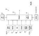
- FIG. 7Ais a block diagram of an exemplary control circuit for the interface device of FIGS. 1 and 2 configured to include and execute gaming applications.
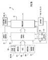
- FIG. 7Bis a block diagram of an exemplary control circuit for the interface device of FIGS. 1 and 2 configured to serve as a game controller for a game processor.
- FIG. 8is a diagrammatic illustration of a series of physically demanding user interface devices according to the present invention arranged in a ring type network topology to facilitate video game play with a plurality of users.
- FIG. 9is a diagrammatic illustration of a series of physically demanding user interface devices according to the present invention arranged in a star type network topology to facilitate video game play with a plurality of users.
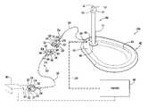
- FIG. 1A user interface device to accommodate a user in a seated position according to the present invention is illustrated in FIG. 1 .
- a user interface device 100 aincludes control circuitry 50 ( FIG. 7A ) including a processor 52 with various gaming applications, and is coupled directly to a monitor 300 to display a game scenario as described below.
- the user interface devicemay serve as a game controller and include control circuitry 50 ( FIG. 7B ) including a processor 62 to process information for transference to a game processor 200 .
- the game processormay be coupled to monitor 300 to display a game scenario.
- the game processorincludes a storage drive and/or unit to receive computer readable media (e.g., CD, DVD, etc.) containing software for various games and a processing device to execute the software to provide games on the monitor.
- the game processormay be implemented by any conventional or other processing or gaming system (e.g., microprocessor system, personal computer, video gaming system, etc.).
- the game processormay be implemented by conventional video game systems, such as PS2 available from Sony, XBOX available from Microsoft or GAMECUBE available from Nintendo.
- the gamesgenerally include characters or objects that are controlled by a user via a controller.
- the usermay control movement and actions of a character or a vehicle (e.g., car, airplane, boat, etc.) to move through a virtual environment displayed on a monitor.
- the controllerincludes a plurality of input devices (e.g., joystick, buttons, etc.) to enable a user to interact with the game.
- a processor executing a gaming applicationreceives signals from the controller and updates a corresponding display to reflect the movements and/or actions of the character or object as indicated by user manipulation of the controller.
- User interface device 100 a of the present inventionis configured to require a user to perform a physically demanding activity or provide physical exertion in order to manipulate the interface device and control a game scenario.
- the deviceis configured to force a user to utilize many of the large muscle groups to interact with the game.
- user interface device 100 aincludes a base 102 preferably in the form of a platform, a joystick 106 and control circuitry 50 ( FIGS. 7A , 7 B).
- Base 102is generally elliptical (or egg-shaped) and includes a recessed or concave surface portion 104 .
- the recessed portionis defined in a rear portion of the base top surface and is configured to contour and support a user in a seated position.
- a control portion 105is defined within a front portion of the base top surface and is raised or elevated relative to recessed portion 104 .
- Control portion 105receives joystick 106 as described below.
- the basemay be placed on any desired surface for game play (e.g., floor, sofa, chair, etc.).
- the base bottom portionis typically smooth with rounded edges and sufficiently wide and deep to support the weight of the user. The user weight provides stability for the interface device in response to forces applied to the joystick by a user to interact with a video game as described below.
- Joystick 106is removably attached to base control portion 105 , and includes a rod 112 extending upward from the base.
- the joystickincludes a length of approximately twenty inches.
- the rodincludes a substantially spherical knob or head 114 attached to the rod top portion with a button type input device 116 disposed on a knob top surface.
- Input device 116preferably enables performance of game selection and weapon firing functions.
- the joystick and/or basemay include other input devices (e.g., buttons, joysticks or other input devices that the user may adjust through weight shifting or by stepping or otherwise triggering sensors) to enable various interaction with the video games.
- the user interface devicemeasures forces and/or motions applied to the joystick by a user as described below (e.g., in the X and Y axes, rotational forces, etc.) to interact with the video game.
- the joystickpreferably includes two degrees of freedom (e.g., motion along X and Y axes) with a range of motion of approximately eighteen inches along each degree of freedom or axis.
- the joystickis preferably constructed of a lightweight material (e.g., hollow polypropylene, etc.) to reduce momentum, while the user interface device includes constraining devices (e.g., damper mechanisms, etc.) to limit velocity of the joystick.
- the combination of low mass and constrained velocityproduces a controlled force of less than approximately 100 Joules, or 70 foot-lbs, that minimizes user injury in the event the joystick clashes with the user during game play. This enables the interface device to be safe, especially for use by children.
- the effort needed to manipulate the joystickmay be adjustable. Accordingly, a substantially annular dial 118 is disposed on control portion 105 about the rod bottom portion to set the desired resistance for the joystick.
- the interface devicemay alternatively include resistance input devices 156 ( FIGS. 7A , 7 B) to enter resistance controls. Devices 156 may be implemented by any conventional or other input devices (e.g., buttons, slides, switches, etc.) and may be disposed at any suitable locations.
- base control portion 105includes a reset button 110 disposed adjacent dial 118 to reset the user interface device, and audio and/or video output ports 108 disposed adjacent reset button 110 to removably receive a cable 270 to connect the user interface device directly to monitor 300 .
- the audio/video portsmay be of any quantity and may be implemented by any conventional or other ports.
- the user interface devicemay include a cable system 220 attached to and extending from the base to connect the interface device to game processor 200 as described below.
- additional input devicesmay be mounted to joystick 106 to enable the user to interact with the game processor (e.g., option selection, weapon firing, etc.)
- joystick 106may include supplemental joystick 121 and buttons 123 disposed on knob 114 and/or rod 112 to enable the user to manipulate these additional devices along with joystick 106 for interaction with a game scenario.
- the interface devicegenerally includes respective signal sources (e.g., variable resistor or potentiometers) to provide signals indicating motion of joystick 121 along X (e.g., left/right motions) and Y (e.g., forward/back motions) axes.
- signal sourcese.g., variable resistor or potentiometers
- joystick 121may be associated with signal sources 125 ( FIG. 7B ) (e.g., variable resistor or potentiometers) to provide signals indicating motion of that joystick along X and Y axes.
- the interface devicemay include switch controls 157 to control function assignment of the interface device input mechanisms (e.g., joysticks 106 , 121 , buttons 116 , 123 , etc.) as described below.
- Switch controls 157may be implemented by any conventional or other input devices (e.g., buttons, slides, switches, etc.).
- the interface devicemay include any quantity of any type of input devices (e.g., buttons, switches, slides, a keypad, joystick, etc.) and signal sources disposed at any location and arranged in any fashion on the interface device.
- the input devicesmay be utilized to enter any desired information (e.g., enter desired user actions for the game, etc.).
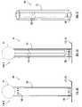
- FIG. 2An alternative user interface device to accommodate a user in a standing position according to the present invention is illustrated in FIG. 2 .
- a user interface device 100 baccording to the present invention includes processor 52 ( FIG. 7A ) with various gaming applications, and is coupled directly to monitor 300 to display a game scenario as described above.
- user interface device 100 bmay include processor 62 ( FIG. 7B ) and be coupled to game processor 200 that displays a game scenario on monitor 300 as described above.
- the game processoris substantially similar to the game processor described above and includes a storage drive and/or unit to receive computer readable media (e.g., CD, DVD, etc.) containing software for various games and a processing device to execute the software to provide games on the monitor.
- computer readable mediae.g., CD, DVD, etc.
- User interface 100 b of the present inventionis configured to require a user to perform a physically demanding activity or provide physical exertion to manipulate the interface device and control a game scenario.
- the deviceis configured to force a user to utilize many of the large muscle groups to interact with the game.
- user interface device 100 bincludes a base 120 preferably in the form of a platform, joystick 106 and control circuitry 50 ( FIGS. 7A , 7 B).
- the joystick and control circuitryare substantially similar to the corresponding components described above.
- Base 120is generally rectangular with rounded corners and supports a user in a standing position on the base top surface.
- the baseis preferably placed on a substantially flat surface for game play (e.g., floor, etc.) and is sufficiently wide and deep to ensure the user remains on the base (e.g., does not accidentally step off) during use.
- the user weightprovides stability for the interface device in response to forces applied to the joystick by a user to interact with a video game as described below.
- Joystick 106is removably attached to the base toward a front base portion, and includes rod 112 extending upward from the base as described above.
- the joystickincludes a length of approximately thirty inches.
- the rodincludes substantially spherical knob or head 114 attached to the rod top portion as described above.
- the rod and knobare substantially similar to the corresponding components described above.
- Base 120further includes input devices 124 disposed on the base top surface toward the base front portion with joystick 106 disposed between the input devices.
- Input devices 124are preferably in the form of buttons that are typically actuated in response to depression or application of force by user feet in order to perform game selection and weapon firing functions as described above. These devices may be positioned to require a user to make a particular effort for actuation (e.g., positioned proximate the far side of the joystick), or be disposed in the area of the base that supports the user. The input devices may further be disabled by the user. Input devices or buttons 124 may be configured in various manners.
- the configurationsmay include a quantity of buttons in the approximate range of two through nine that are arranged to support several game interactions of varying complexity (e.g., from simple game interactions to complex game interactions, such as dance type game interactions, etc.).
- the joystick and/or basemay include other input devices (e.g., buttons, joysticks or other input devices that the user may adjust through weight shifting or by stepping or otherwise triggering sensors) to enable various interaction with the video games.
- User interface 100 bmeasures forces and/or motions applied to the joystick by a user as described below (e.g., in the X and Y axes, rotational forces, etc.) to interact with the video game.
- the joystickpreferably includes two degrees of freedom (e.g., motion along X and Y axes) with a range of motion of approximately twenty-two inches along each degree of freedom or axis.
- the joystickis preferably constructed of a lightweight material (e.g., hollow polypropylene, etc.) to reduce momentum, while the user interface device includes constraining devices (e.g., damper mechanisms, etc.) to limit velocity of the joystick.
- the combination of low mass and constrained velocityproduces a controlled force of less than approximately 100 Joules, or 70 foot-lbs, that minimizes user injury in the event the joystick clashes with the user during game play. This enables the interface device to be safe, especially for use by children.
- substantially annular dial 118may be disposed about the rod bottom portion to enable a user to set the desired resistance for the joystick.
- the interface devicemay alternatively include resistance input devices 156 disposed at any suitable locations to enter resistance controls.
- the baseincludes reset button 110 disposed adjacent dial 118 to reset the user interface device, and audio and/or video output ports 108 disposed on a base front surface to removably receive cable 270 to connect the user interface device directly to monitor 300 as described above.
- the dial, resistance input devices, reset button and audio/video portsare substantially similar to the corresponding components described above.
- user interface device 100 bmay include cable system 220 attached to and extending from the base to connect the interface device to game processor 200 as described above.
- additional input devicesmay be mounted to joystick 106 to enable the user to interact with the game processor (e.g., option selection, weapon firing, etc.) as described above.
- joystick 106may include supplemental joystick 121 and buttons 123 disposed on knob 114 and/or rod 112 to enable the user to manipulate these additional devices along with joystick 106 for interaction with a game scenario as described above.
- the interface devicegenerally includes respective signal sources 125 ( FIG.
- the interface devicemay include switch controls 157 to control function assignment of interface device input devices (e.g., joysticks 106 , 121 , buttons 123 , 124 , etc.) as described above.
- the interface devicemay include any quantity of any type of input devices (e.g., buttons, switches, slides, a keypad, joystick, etc.) and signal sources disposed at any location and arranged in any fashion on the interface device.
- the input devicesmay be utilized to enter any desired information (e.g., enter desired user actions for the game, etc.).
- Joystick 106may be attached to base 102 , 120 in various manners with the interface device employing varying techniques to measure manipulation of the joystick relative to the base.
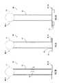
- joystick 106may be directly attached to base 102 , 120 as illustrated in FIGS. 3A-3G .
- interface device 100 a , 100 bmay be in the form of an integral unit with joystick 106 being mounted fixedly to base 102 , 120 (e.g., without moving components, pivots, joints or gimbals). In this case, manipulation of joystick 106 and/or knob 114 may be monitored in various manners. Referring to FIG.
- a camera or photodetector 204may be mounted within rod 112 at the rod end proximate base 102 , 120 with the rod interior within the detector field of view.
- Passive colored patterns or active light emitting or other illuminating devices 202e.g., LEDs, etc.
- the photodetector and light emitting devicesmay be implemented by any conventional or other devices to emit and detect light or other energy media (e.g., camera, LED, photodetectors, etc.), and may be disposed at any suitable locations.
- Detector 204captures images of the field of view (e.g., rod interior), where the patterns or emitted light are displaced within the rod and captured image due to manipulation or deflection of the rod by a user.
- the pattern or emitted light arrangementshifts within the field of view in accordance with joystick motion and is displaced within the resulting image.
- the newly captured imagemay be compared to the reference image by processor 52 , 62 via conventional image processing techniques to determine the amount of displacement of the pattern or emitted light arrangement within the image. This displacement is proportional to the amount of rod deflection.
- the processorprocesses the captured image to determine the rod deflection and updates the game scenario in accordance with the forces applied to the joystick by a user.
- FIGS. 3B-3CAn alternative arrangement to measure rod deflection is illustrated in FIGS. 3B-3C .
- a series of cables 206may be disposed along the interior of rod 112 .
- cables 206may include four cables each angularly offset from each other by approximately ninety degrees; however, the rod may include any quantity of cables disposed within the rod in any fashion.
- the cablesextend from a rod portion proximate knob 114 toward the rod portion proximate base 102 , 120 .
- a set of potentiometers 208are disposed within rod 112 proximate base 102 , 120 with each cable coupled to a corresponding potentiometer to control the variable resistance of that potentiometer.
- the potentiometersmay be of any quantity, may be disposed at any suitable locations, and may be implemented by any conventional or other devices with any variable property (e.g., electrical, chemical, mechanical, resistance, capacitance, magnetic, etc.) to indicate rod deflection.
- variable propertye.g., electrical, chemical, mechanical, resistance, capacitance, magnetic, etc.
- the cables attached to these surfacesare consequently manipulated by the stretching (e.g., elongated or pulled for stretching, pushed or compressed for contracting, etc.) and alter resistance of corresponding potentiometers 208 .
- the altered resistancesresult in a voltage change that may be measured by control circuitry 50 ( FIGS. 7A , 7 B) to determine the amount of deflection or manipulation of the joystick.
- the control circuitryprocesses the measured information to update the game scenario in accordance with the forces applied to the joystick by a user.
- strain gaugesmay be employed to measure deflection of rod 112 .
- strain gauge sensors 210 , 212may be arranged at suitable locations on the rod interior surface, preferably at an intermediate location. These sensors measure the amount of a strain deformation applied to the joystick as a result of the user applying pushing, pulling or lateral forces to the joystick.
- sensor 212may measure forces applied to the joystick along an X-axis (e.g., lateral or left/right forces), while sensor 210 may measure forces applied to the joystick along a Y-axis (e.g., push/pull or forward/backward forces).
- the joystick manipulationmay further be measured via switches as illustrated in FIG. 3E .
- a series of switches 214may be mounted in base 102 , 120 around the periphery of rod 112 .
- the rodmay include contacts or actuating members 215 disposed on the rod exterior surface, preferably coincident a corresponding switch 214 .
- the switchesmay be implemented by any conventional or other switching devices (e.g., switches, contacts, relays, etc.), while the contacts may be implemented by any conventional or other contacts or members to actuate the switches.
- the switches and contactsmay be of any quantity and may be disposed at any suitable locations. When a user applies force to the joystick, the joystick is typically displaced, where one or more contacts 215 may actuate corresponding switches 214 .
- the joystick manipulationmay be measured by a series of linear damper mechanisms.
- a series of linear damper mechanisms 216are mounted in base 102 , 120 and around the periphery of the bottom portion of rod 112 .
- the damper mechanismmay be implemented by any conventional or other damping devices or mechanisms (e.g., dampers, elastic members, etc.), such as the damping mechanisms disclosed in U.S. Pat. No. 4,588,054 (LeBaron), the disclosure of which is incorporated herein by reference in its entirety.
- each damper mechanism 216is in the form of a shock absorber and includes a cylinder 211 and a piston 217 .
- the pistonincludes a piston head 207 disposed within cylinder 211 and a piston rod 209 coupled to head 207 and extending therefrom external of the cylinder.
- Cylinder 211is mounted to base 102 , 120 , while the distal end of piston rod 209 external of the cylinder is coupled to the lower portion of rod 112 .
- the pistonis urged in a reciprocal motion within cylinder 211 in response to joystick motion.
- the damper mechanismmay further include a resistance mechanism to impede the reciprocal motion of the piston within cylinder 211 .
- the resistance mechanismmay be in the form of a spring disposed within cylinder 211 and coupled to the piston, or in the form of pressurized fluid within the cylinder.
- Damper mechanism 216further includes a sensing device 219 to measure the amount of piston motion.
- the sensing devicemay be coupled to the piston rod and/or head and may be implemented by any suitable sensors (e.g., encoders, potentiometers, etc.).
- piston rods 209 coupled to the joystickproduce a reciprocal piston motion within corresponding cylinders.
- the positions (or amount and direction of motion) of the pistons within the damper mechanismsare measured by corresponding sensors 219 .
- These measurementsindicate joystick manipulation and are provided to control circuitry 50 ( FIGS. 7A , 7 B).
- the control circuitryprocesses the information to update the game scenario in accordance with the forces applied to the joystick by a user.
- joystick manipulationmay be determined based on forces applied to the base as illustrated in FIG. 3G .
- base 102 , 120includes sensors 218 , preferably in the form of limit switches or load cells. These sensors may be disposed at any suitable location on or within the base and measure the amount of tilting forces applied to the base (e.g., the amount of base tilting or potential tilting). Since joystick 106 is connected directly to base 102 , 120 as described above, forces applied to joystick 106 or knob 114 follow a load path through the base and to the floor or other supporting surface, thereby resulting in a signal measurable by sensors 218 .
- the sensorsmeasure these forces (or tilt of the base) to determine the amount of force applied to the joystick (e.g., joystick manipulation).
- Sensors 218are connected to control circuitry 50 ( FIGS. 7A , 7 B), where the control circuitry processes the information to update the game scenario in accordance with the forces applied to the joystick by a user.
- Interface device processor 52 , 62may include image recognition software to process the captured images and determine the amount of deflection or manipulation of joystick 106 by the user based on the displaced patterns or emitted light in the resulting image as described above.
- the pattern or arrangement of emitted lightmay be in a certain area (e.g., substantially centered, etc.) within the detector field of view when the joystick is in a reference position (e.g., centered, etc.). This or a previously captured image may serve as a reference image.
- the pattern or emitted light arrangementshifts within the field of view in accordance with joystick motion and is displaced within the resulting image.
- FIG. 4BAn alternative arrangement to measure joystick manipulation is illustrated in FIG. 4B .
- a set of potentiometers 208are disposed within base 102 , 120 proximate socket 282 with each potentiometer coupled to or in contact with ball 280 .
- the potentiometersmay be of any quantity, may be disposed at any suitable locations, and may be implemented by any conventional or other devices with any variable property (e.g., electrical, chemical, mechanical, resistance, capacitance, magnetic, etc.).
- ball 280rotates or slides within, and relative to, socket 280 .
- the joystick manipulationmay further be measured via switches as illustrated in FIG. 4C .
- a series of switches 214are mounted in base 102 , 120 proximate socket 282 .
- Ball 280 and/or rod 112may include contacts or actuating members 215 disposed on the exterior surface thereof, preferably coincident a corresponding switch 214 .
- the switches and contactsare substantially similar to the switches and contacts described above, may be of any quantity and may be disposed at any suitable locations.
- ball 280rotates or slides within, and relative to, socket 280 , where one or more contacts 215 may actuate corresponding switches 214 .
- the actuated switcheseach provide a signal to control circuitry 50 ( FIGS. 7A , 7 B).
- the particular switches actuated in response to manipulation of the joystickindicate the direction and motion of the joystick by the user.
- the control circuitryprocesses the information to update the game scenario in accordance with the forces applied to the joystick by a user.
- the joystick manipulationmay be measured by a series of linear damper mechanisms.
- a series of linear damper mechanisms 216is mounted in base 102 , 120 and around the periphery of the bottom tapered portion of rod 112 .
- the damper mechanismis substantially similar to the damper mechanism described above and, by way of example, is in the form of a shock absorber including cylinder 211 and piston 217 .
- the pistonincludes piston head 207 disposed within cylinder 211 and piston rod 209 coupled to head 207 and extending therefrom external of the cylinder as described above. Cylinder 211 is mounted to base 102 , 120 , while the distal end of piston rod 209 external of the cylinder is coupled to the lower tapered portion of rod 112 .
- the pistonis urged in a reciprocal motion within cylinder 211 in response to joystick motion.
- the damper mechanismfurther includes a resistance mechanism to impede the reciprocal motion of the piston within cylinder 211 as described above.
- the resistance mechanismmay be in the form of a spring disposed within cylinder 211 and coupled to the piston, or in the form of pressurized fluid within the cylinder as described above.
- Damper mechanism 216further includes sensing device 219 to measure the amount of piston motion as described above.
- the sensing devicemay be coupled to the piston rod and/or head and may be implemented by any suitable sensors (e.g., encoders, potentiometers, etc.).
- piston rods 209 coupled to the joystickproduce a reciprocal piston motion within corresponding cylinders.
- the positions (or amount and direction of motion) of the pistons within the damper mechanismsare measured by corresponding sensors 219 .
- These measurementsindicate joystick manipulation and are provided to control circuitry 50 ( FIGS. 7A , 7 B).
- the control circuitryprocesses the information to update the game scenario in accordance with the forces applied to the joystick by a user.
- Joystick 106may further be attached to base 102 , 120 via a universal joint as illustrated in FIGS. 5A-5C .
- a universal joint 290is disposed within base 102 , 120 with rod 112 attached to the joint top surface.
- the universal jointmay be implemented by any conventional or other coupling devices or mechanisms (e.g., joints, gimbals, etc.), such as the universal joints disclosed in U.S. Pat. No. 6,994,627 (Menosky et al.), the disclosure of which is incorporated herein by reference in its entirety.
- joint 290includes a rod pivot member 292 , a base pivot member 296 and a cross member 295 interconnecting the rod and pivot members.
- Rod pivot member 292includes a pair of legs 294 attached to a substantially circular platform 291 .
- the legsare angularly offset from each other by approximately one-hundred eighty degrees and each include an aperture 285 to receive cross member 295 .
- Rod 112is attached to the platform top surface.
- Base pivot member 296includes a pair of legs 298 attached to a generally circular platform 293 .
- the legsare angularly offset from each other by approximately one-hundred eighty degrees and each include an aperture 287 to receive cross member 295 .
- Base 102 , 120is coupled to the platform bottom surface in a manner enabling rotation of the base pivot member relative to the base. This rotational coupling may be implemented by any conventional or other techniques (e.g., spindle, axle, rollers, etc.).
- the rotational coupling of platform 293 to the baseenables joystick 106 to attain any desired angular position.
- Rod pivot member 292is disposed over base pivot member 296 with pairs of legs 294 , 298 in facing relation and angularly offset by approximately ninety degrees.
- Projections 281 , 283are inserted within apertures 287 of base pivot member legs 298 and enable the rod pivot member and joystick 106 to rotate about a second axis (e.g., a longitudinal axis through projections 281 , 283 ) orthogonal to the first axis.
- a second axise.g., a longitudinal axis through projections 281 , 283
- the universal jointenables the joystick to be manipulated along two orthogonal axes at any desired angular position.
- Manipulation of joystick 106 and/or knob 114 in this type of configurationmay be monitored in various manners with the interface device employing varying techniques to measure the joystick manipulation relative to the base.
- a set of potentiometersmay be utilized to measure manipulation of joystick 106 .
- potentiometers 208may be disposed on base pivot member platform 293 and at least one leg 294 , 298 of each of the base and rod pivot members.
- the leg potentiometersare coupled to the corresponding legs and/or cross member in a manner enabling rotation of the legs about the cross member to alter the resistance controls of those potentiometers.
- the platform potentiometermay be coupled to the platform and/or base in a manner enabling rotation of the platform relative to the base to alter the resistance controls of that potentiometer.
- the potentiometersmay be of any quantity, may be disposed at any suitable locations, and may be implemented by any conventional or other devices with any variable property (e.g., electrical, chemical, mechanical, resistance, capacitance, magnetic, etc.).
- the base pivot membermay rotate relative to the base, while the rod pivot member may rotate about the first and/or second orthogonal axes.
- the base pivot member rotationalters the resistance controls of the corresponding potentiometer mounted to that platform to adjust the potentiometer resistance.
- the rod pivot member rotationalters the resistance controls of the corresponding potentiometers mounted to the rod and base pivot member legs to adjust the resistances of those potentiometers.
- the altered resistancesresult in a voltage change that may be measured by control circuitry 50 ( FIGS. 7A , 7 B) to determine the amount of manipulation of the joystick.
- the control circuitryreceives and processes the information from the potentiometers to update the game scenario in accordance with the forces applied to the joystick by a user.
- the joystick manipulationmay further be measured via switches as illustrated in FIG. 5B .
- a series of switches 214are mounted in base 102 , 120 proximate the lower portion of rod 112 .
- the rod lower portionmay include contacts or actuating members 215 disposed on the rod exterior surface, preferably coincident a corresponding switch 214 .
- the switches and contactsare substantially similar to the switches and contacts described above, may be of any quantity and may be disposed at any suitable locations.
- the actuated switcheseach provide a signal to control circuitry 50 ( FIGS. 7A , 7 B).
- the particular switches actuated in response to manipulation of the joystickindicate the direction and motion of the joystick by the user.
- the control circuitryprocesses the information to update the game scenario in accordance with the forces applied to the joystick by a user.
- the joystick manipulationmay be measured by a series of linear damper mechanisms.
- a series of linear damper mechanisms 216is mounted in base 102 , 120 and around the periphery of the bottom portion of rod 112 .
- the damper mechanismis substantially similar to the damper mechanism described above and, by way of example, is in the form of a shock absorber including cylinder 211 and piston 217 .
- the pistonincludes piston head 207 disposed within cylinder 211 and piston rod 209 coupled to head 207 and extending therefrom external of the cylinder as described above. Cylinder 211 is mounted to base 102 , 120 , while the distal end of piston rod 209 external of the cylinder is coupled to the lower portion of rod 112 .
- the pistonis urged in a reciprocal motion within cylinder 211 in response to joystick motion.
- the damper mechanismfurther includes a resistance mechanism to impede the reciprocal motion of the piston within cylinder 211 as described above.
- the resistance mechanismmay be in the form of a spring disposed within cylinder 211 and coupled to the piston, or in the form of pressurized fluid within the cylinder as described above.
- Damper mechanism 216further includes sensing device 219 to measure the amount of piston motion as described above.
- the sensing devicemay be coupled to the piston rod and/or head and may be implemented by any suitable sensors (e.g., encoders, potentiometers, etc.).
- piston rods 209 coupled to the joystickproduce a reciprocal piston motion within corresponding cylinders.
- the positions (or amount and direction of motion) of the pistons within the damper mechanismsare measured by corresponding sensors 219 .
- These measurementsindicate joystick manipulation and are provided to control circuitry 50 ( FIGS. 7A , 7 B).
- the control circuitryprocesses the information to update the game scenario in accordance with the forces applied to the joystick by a user.
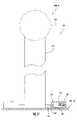
- joystick 106may attached to base 102 , 120 via a sleeve arrangement as illustrated in FIGS. 6A-6D .
- base 102 , 120may include a substantially cylindrical stub 302 .
- the stubincludes transverse dimensions substantially the same as those of rod 112 of joystick 106 .
- An elastic sleeve 304e.g., flexible material, spring, etc.
- the sleevemay be disposed over the stub, where joystick 106 is disposed within sleeve 304 with the rod bottom portion residing in the stub.
- the longitudinal dimension of the sleeveis slightly less than those of rod 112 to enable knob 114 to reside external of the sleeve for manipulation by a user.
- Sleeve 304may be replaced with sleeves constructed of materials with greater or less elasticity to adjust the amount of force required by a user to manipulate or deflect joystick 106 .
- Manipulation of joystick 106 and/or knob 114 within this type of configurationmay be monitored in various manners with the interface device employing varying techniques to measure the joystick manipulation relative to the base.
- a camera or photodetectormay be utilized to measure joystick manipulation in substantially the same manner described above.
- camera or photodetector 204may be mounted within stub 302 with knob 114 within the detector field of view through rod 112 .
- Passive colored patterns or active light emitting or other illuminating devices 202may be placed at the other end of rod 112 toward knob 114 .
- the photodetector and light emitting devicesare substantially similar to the devices described above and may be disposed at any suitable locations.
- Detector 204captures images of the field of view, where the patterns or emitted light are displaced within the captured image due to manipulation or deflection of the joystick by a user.
- Interface device processor 52 , 62may include image recognition software to process the captured images and determine the amount of deflection or manipulation of joystick 106 by the user based on the displaced patterns or emitted light in the resulting image as described above.
- the pattern or arrangement of emitted lightmay be in a certain area (e.g., substantially centered, etc.) within the detector field of view when the joystick is in a reference position (e.g., centered, etc.). This or a previously captured image may serve as a reference image.
- the pattern or emitted light arrangementshifts within the field of view in accordance with joystick motion and is displaced within the resulting image.
- the newly captured imagemay be compared to the reference image via conventional image processing techniques as described above to determine the amount of displacement of the pattern or emitted light arrangement within the image. This displacement is proportional to the amount of joystick manipulation (e.g., direction, distance of joystick motion, etc.).
- the processorprocesses the captured image to determine the joystick manipulation and updates the game scenario in accordance with the forces applied to the joystick by a user.
- the strain gauge sensorsmay be arranged with respect to the stub and/or joystick in any suitable manner to measure forces, such as the manners disclosed in the aforementioned patent applications.
- the strain gauge sensorsmay be attached directly or indirectly to a stub and/or joystick exterior or interior surface to measure the applied forces.
- the resistance of the strain gauge sensorsis measured to determine deflection or manipulation of the joystick as described above.
- the strain gauge sensorsare connected to control circuitry 50 ( FIGS. 7A , 7 B) that processes the information to update the game scenario in accordance with strain forces applied to the joystick by a user.
- the joystick manipulationmay further be measured via switches as illustrated in FIG. 6C .
- a series of switches 214is mounted in base 102 , 120 proximate the stub periphery.
- the stubmay include contacts or actuating members 215 disposed on the stub exterior surface, preferably coincident a corresponding switch 214 .
- the switches and contactsare substantially similar to the switches and contacts described above, may be of any quantity and may be disposed at any suitable locations.
- the actuated switcheseach provide a signal to control circuitry 50 ( FIGS. 7A , 7 B).
- the particular switches actuated in response to manipulation of the joystickindicate the direction and motion of the joystick by the user.
- the control circuitryprocesses the information to update the game scenario in accordance with the forces applied to the joystick by a user.
- the joystick manipulationmay be measured by a series of linear damper mechanisms.
- a series of linear damper mechanisms 216is mounted in base 102 , 120 and around the periphery of sleeve 304 .
- the damper mechanismis substantially similar to the damper mechanism described above and, by way of example, is in the form of a shock absorber including cylinder 211 and piston 217 .
- the pistonincludes piston head 207 disposed within cylinder 211 and piston rod 209 coupled to head 207 and extending therefrom external of the cylinder as described above.
- Cylinder 211is mounted to base 102 , 120 , while the distal end of piston rod 209 external of the cylinder is coupled to the lower portion of sleeve 304 .
- the pistonis urged in a reciprocal motion within cylinder 211 in response to joystick motion.
- the damper mechanismfurther includes a resistance mechanism to impede the reciprocal motion of the piston within cylinder 211 as described above.
- the resistance mechanismmay be in the form of a spring disposed within cylinder 211 and coupled to the piston, or in the form of pressurized fluid within the cylinder as described above.
- Damper mechanism 216further includes sensing device 219 to measure the amount of piston motion as described above.
- the sensing devicemay be coupled to the piston rod and/or head and may be implemented by any suitable sensors (e.g., encoders, potentiometers, etc.).
- sensorse.g., encoders, potentiometers, etc.
- piston rods 209 coupled to the sleeveproduce a reciprocal piston motion within corresponding cylinders.
- the positions (or amount and direction of motion) of the pistons within the damper mechanismsare measured by corresponding sensors 219 .
- These measurementsindicate joystick manipulation and are provided to control circuitry 50 ( FIGS. 7A , 7 B).
- the control circuitryprocesses the information to update the game scenario in accordance with the forces applied to the joystick by a user.
- the level of exertion required by a user in order to achieve a particular response in the video game scenariomay be adjusted in various manners within the above configurations for interface device 100 a , 100 b .
- the level of exertion required by a usermay be adjustable by changing damping or elastic characteristics.
- a sleevemay be positioned over rod 112 and firmly attached to base 102 , 120 , where the position and rigidity of the sleeve may be adjusted to alter the force required by a user.
- the quantity of sleeves employed over the rodmay be altered to adjust the force required by a user (e.g., the greater the quantity of sleeves, the greater the force required by a user).
- an elastic materiale.g., a spring, rubber elastomer, etc.
- an elastic materiale.g., a spring, rubber elastomer, etc.
- the flow of fluid to linear damper mechanisms 216may be controlled to alter the damper resistance and force required by a user.
- the positions of the linear damper mechanismsmay be adjusted relative to the joystick to alter the leverage and, hence, the force required by a user.
- the resistance levelsmay further be adjusted by processor 52 , 62 ( FIGS. 7A , 7 B) during processing of the various measurements as described below. These measurements may be weighted or amplified during processing, where greater or less force may need to be applied by a user to overcome the weighting (e.g., the greater the weight applied, the less force required by a user). Resistance levels (e.g., for the processor, fluid control, etc.) may be entered by a user via dial 118 or resistance input devices 156 as described above. Alternatively, or in combination with user input, the resistance levels may be controlled by control circuitry 50 based upon conditions within the video game scenario, such as changing wind conditions, changing grade of the terrain (e.g., going uphill), etc.
- control circuitry 50is preferably disposed or housed within base 102 , 120 and includes processor 52 coupled to the particular sensors and input mechanisms described above (e.g., strain gauges 210 , 212 , switches 214 , potentiometers 208 , photodetector 204 , damper sensors 219 , input devices or buttons 110 , 116 , 124 , 156 , etc.) depending upon the particular configuration employed.
- a conventional power supply(not shown) provides appropriate power signals to each of the control circuitry components as necessary.
- the interface devicemay be powered by a battery and/or any other suitable power source (e.g., wall outlet, etc.).
- a power switch(not shown) may further be included to activate the circuit components.
- the signals from the various sensors and input mechanismsare transmitted to a respective predetermined memory location within processor 52 .
- the processormay be implemented by any conventional or other processor and may include circuitry to and/or convert analog signals from the various devices to digital values for processing.
- the processorsamples the memory locations at predetermined time intervals (e.g., preferably on the order of ten milliseconds or less) to continuously process information (e.g., determine input mechanism manipulation, determine joystick manipulation, etc.) to update and/or respond to an executing gaming application.
- the processormay process raw digital values in any fashion to account for various calibrations or to properly adjust the values within quantization ranges for digitized analog signals.
- the processorreceives the measurements from the various sensors (e.g., and/or other information from input devices 110 , 116 , 124 ) to determine joystick and input mechanism manipulation.
- the processormay provide various information for display to a user (e.g., the amount of work performed by the user during a particular exercise session, a game scenario, time or elapsed time and/or any other exercise or game related information) on monitor 300 and/or another local or remote display (not shown).
- the processormay receive signals from strain gauges 210 , 212 and determine the amount of joystick manipulation or deflection along the axes associated with the strain gauges to update a game scenario.
- the processormay receive signals from switches 214 , where the switch signals may be in the form of a digital word with each bit indicating the status of a corresponding switch.
- the processoridentifies the particular switches that have been actuated to determine the joystick manipulation (e.g., based on the actuated switch location) to update the game scenario.
- the processormay receive signals from various potentiometers 208 indicating a change in their resistance (e.g., due to rod deflection, motion of the ball within the socket, motion of the universal joint, etc.) to determine the amount of joystick manipulation or deflection to update a game scenario.
- the processormay receive signals from sensors 219 of the damper mechanisms indicating the piston position or motion to determine the amount of joystick manipulation or deflection to update a game scenario.
- the processormay receive captured images from photodetector or camera 204 .
- the processormay include image recognition software to process the captured images and determine the amount of deflection or manipulation of the joystick by the user based on displaced patterns or emitted light in the resulting image as described above.
- a pattern or arrangement of emitted lightmay be within a certain area in the detector field of view in the absence of joystick deflection or manipulation. This or a previously captured image may serve as a reference image.
- the pattern or emitted light arrangementshifts within the field of view in accordance with joystick motion and is displaced within the resulting image.
- the newly captured imagemay be compared to the reference image via conventional image processing techniques to determine the amount of displacement of the pattern or emitted light arrangement within the image (e.g., indicating the amount of joystick manipulation or deflection).
- the processorprocesses the captured image to determine the joystick manipulation or deflection and updates the game scenario in accordance with the forces applied to the joystick by a user.
- the processormay further control resistance levels required by the user to interact with the game scenario in accordance with settings provided by dial 118 and/or resistance input devices 156 .
- the processormay apply weights to the sensor measurements. These weights may be based on information entered by the user. Since greater measurement values correspond to a greater force, increasing the weight values enables a user to exert less force to achieve a particular force value, thereby effectively lowering the resistance of the interface device for the user. Conversely, reducing the weight value requires a user to exert greater force to achieve the particular force value, thereby increasing the resistance of the interface device for the user.
- Processor 52includes and executes gaming software.
- the processorprocesses the received signals and updates the executing gaming scenario in accordance with manipulation of the joystick and/or input mechanisms (e.g., devices or buttons 116 , 124 ).
- the processormay include, or be coupled to, an audio/visual (A/V) module 56 that generates signals (e.g., video, audio, etc.) for transference from interface device 100 a , 100 b directly to monitor 300 .
- the A/V modulemay be implemented by any conventional or other processing system or circuitry (e.g., video processor, digital signal processor (DSP), etc.) providing audio and/or video signals.
- the signalsmay be provided to the monitor via cable 270 ( FIGS.
- the cablemay be implemented by any conventional or other cable suitable to transfer video and/or audio signals.
- a usermay connect the interface device directly to a television set or other monitor through either an RF connector (e.g., via channels three or four), or through the monitor audio/visual ports (e.g., via RCA type connectors, etc.).
- the processorperforms a reset or reboot operation in response to actuation of reset button 110 .
- the user interface devicemay further include communication ports 54 within control circuitry 50 and be coupled to or networked with other user interface devices to enable plural users to compete against each other in a game scenario as described below.
- the communication portsmay be of any quantity, may transmit and/or receive information, and may be implemented by any conventional or other communication ports (e.g., serial or USB, parallel, wired, wireless, Bluetooth, etc.).
- Processor 52is coupled to the communication ports and receives information from the other user interface devices, preferably indicating desired actions from other users (e.g., manipulation of joystick 106 and/or other input devices, etc.).
- the processorprocesses the received information to update the game scenario in accordance with the user actions for display on monitor 300 .
- the processormay further provide information indicating desired actions of a user (e.g., manipulation of joystick 106 and/or other input devices, etc.) to communication ports 54 for transmission to other user interface devices.
- control circuitry 50is preferably disposed or housed within base 102 , 120 and includes processor 62 coupled to the particular sensors and input mechanisms described above (e.g., strain gauges 210 , 212 , switches 214 , potentiometers 208 , photodetector 204 , damper sensors 219 , input devices or buttons 110 , 116 , 123 , 124 , 156 , joystick 121 , etc.) depending upon the particular configuration employed.
- a conventional power supply(not shown) provides appropriate power signals to each of the control circuitry components as necessary.
- the interface devicemay be powered by a battery and/or any other suitable power source (e.g., wall outlet, game processor, etc.).
- a power switch(not shown) may further be included to activate the circuit components.
- the signals from the various sensors and input mechanismsare transmitted to a respective predetermined memory location within processor 62 .
- the processoris similar to processor 52 described above, may be implemented by any conventional or other processor, and may include circuitry to and/or convert analog signals from the various devices to digital values for processing.
- Processor 62samples the memory locations at predetermined time intervals (e.g., preferably on the order of ten milliseconds or less) to continuously process information (e.g., determine input mechanism manipulation, determine joystick manipulation, etc.) to update and/or respond to an executing gaming application on game processor 200 .
- Processor 62may process raw digital values in any fashion to account for various calibrations or to properly adjust the values within quantization ranges for digitized analog signals.
- Processor 62receives the measurements from the various sensors (e.g., and/or other information from input devices 110 , 116 , 121 , 123 , 124 ) to determine joystick and input mechanism manipulation, and may provide various information for display to a user (e.g., the amount of work performed by the user during a particular exercise session, a game scenario, time or elapsed time and/or any other exercise or game related information) on monitor 300 and/or another local or remote display (not shown) in substantially the same manner described above.
- a usere.g., the amount of work performed by the user during a particular exercise session, a game scenario, time or elapsed time and/or any other exercise or game related information
- the processormay receive captured images from photodetector or camera 204 and may include image recognition software to process the captured images and determine the amount of deflection or manipulation of the joystick by the user based on displaced patterns or emitted light in the resulting image as described above.
- the processorperforms a reset or reboot operation in response to actuation of reset button 110 .
- the responsiveness of the interface devicemay be adjusted to permit small amounts of rod deflection or manipulation to result in meaningful input to the game processor. This enables the user to be competitive in the game scenario, where user responses or reactions to the game may be delayed due to the physical exertion required to enter desired actions for the game on the interface device.
- the measurementsmay be amplified by amplification devices or circuitry (e.g., an amplifier 203 may be disposed between strain gauges 210 , 212 and processor 62 ), or the processor may apply weights to the measurements as described above.
- the processormay further control resistance levels required by the user to interact with the game scenario in accordance with settings provided by dial 118 and/or resistance input devices 156 as described above. For example, the processor may apply weights to the sensor measurements based on information entered by the user as described above.
- Processor 62processes and arranges the received signals into suitable data packets for transmission to game processor 200 .
- the data packetsare in a format resembling data produced by a standard peripheral device (e.g., game controller, etc.).
- the processormay construct a data packet for a game processor (e.g., PS2, XBOX, GAMECUBE, personal computer, etc.) that includes the status of all interface device input mechanisms (e.g., buttons 116 , 124 , etc.) and the processed values from each sensor.
- the data packetmay include header information, X-axis information indicating a measurement for joystick 106 and/or 121 along this axis, Y-axis information indicating a measurement for joystick 106 and/or 121 along this axis, rudder or steering information, throttle or rate information and additional information relating to the status of input mechanisms (e.g., buttons, supplemental joystick, etc.). Additional packet locations may be associated with data received from other input mechanisms connected with the processor, where the input mechanisms represent additional operational criteria for the scenario (e.g., the firing of a weapon in the scenario when the user presses an input button, throttle, etc.).
- the game processorprocesses the information or data packets in substantially the same manner as that for information received from a conventional peripheral (e.g., game controller, etc.) to update and/or respond to an executing gaming application (e.g., game, etc.).
- joysticks 106 , 121 and the input mechanismsmay be selectively configured or assigned to game functions.
- processor 62may generate the data packets for the game processor in accordance with controls from switch controls 157 .
- measurements from the various sensors or input mechanismse.g., joysticks 106 , 121 , input devices or buttons 116 , 123 , 124 , etc.
- the measurements for joystick 106are placed in the data packet location the game processor expects to receive steering information.
- Other functionsmay be associated with input mechanisms in a similar manner.
- the game processorprocesses the information or packets as described above to update and/or respond to an executing gaming application (e.g., game, etc.).
- joysticks 106 , 121 and the input mechanismsmay be selectively configured or assigned to game functions via a switching device 158 as described in the aforementioned patent applications.
- switching device 158receives the signals from the various sensors and input mechanisms and is coupled to switch controls 157 and processor 62 .
- Switching device 158enables a user to selectively configure the interface device for game functions as described below.
- joystick 106FIGS. 1-2
- joystick 121serves as the left controller joystick, where the functions of the joysticks with respect to a game may be selectively assigned by a user as described below.
- joystick 106may serve as any joystick or other input device.
- the switching devicereceives information from the sensors and input mechanisms, and is coupled to the inputs of processor 62 .
- the switching devicebasically enables information for input mechanisms to be selectively placed on the processor inputs corresponding to the desired game functions.
- the processor inputsare typically mapped to game functions in accordance with the game software executed by game processor 200 .
- the switching devicebasically couples the signals from the desired devices (e.g., joysticks 106 , 121 , buttons 110 , 116 , 123 , 124 , etc.) to the processor inputs corresponding to the desired game functions in accordance with controls from a user entered via switch controls 157 .
- Applications of high complexity with respect to blending or assigning game functionsmay require additional selector switches and various combinations of selector switch settings.
- joystick 106may individually perform the functions of two joysticks in accordance with the connections, such as accelerator and steering functions.
- application of a forward force to joystick 106may serve as the accelerator, while lateral force applied to joystick 106 may serve as the steering function.
- Switching device 158may be implemented by any quantity of any conventional or other devices capable of switching signals (e.g., switches, multiplexers, cross-bar switch, analog switches, digital switches, routers, logic, gate arrays, logic arrays, etc.) to accomplish the function assignments for the interface device.
- the signals from the switching device outputsare transmitted to a respective predetermined memory location within processor 62 as described above.
- the signal processorsamples the memory locations at predetermined time intervals to continuously process and send information to the game processor to update and/or respond to an executing gaming application as described above.
- the interface devicemay serve as a game controller that is operable with a wide variety of video game processors or other systems including PS2, XBOX and GAMECUBE systems, and various personal or other computers (e.g., personal computers with Microsoft WINDOWS and Apple Mac OS X operating systems).
- Interface device 100 a , 100 bincludes a cable system that facilitates connection and communication between the interface device and multiple (e.g., two or more) video game processors. Referring back to FIGS. 1-2 , cable system 220 is connected to and extends from base 102 , 120 . Cable system 220 is substantially similar to the cable system described in aforementioned U.S. patent application Ser. No.
- 11/097,370includes a flexible and hollow body 224 that extends into base 102 , 120 to receive and retain wiring that is connected with processor 62 ( FIG. 7B ) within the base.
- the cablemay connect with the interface device at any other suitable location and/or in any other suitable manner.
- a number of separately and independently extending wiresare sheathed within and extend the length of cable body 224 .
- the wiresare configured for providing an electrical contact or link between processor 62 and a specific video game processor as described below.
- Cable body 224extends a selected distance from interface device 100 a , 100 b and connects with a generally rectangular housing 226 .
- a number of flexible and hollow cables 227 , 230 , 240 , 250extend from housing 226 .
- the wiring within cable body 224extends within housing 226 for transfer of signals to wiring sets directed into and through a respective one of the output cables 227 , 230 , 240 , 250 .
- housing 226serves as a junction location for the transfer of signals between wiring within cable body 224 and respective wiring sets of the output cables, where each output cable includes a wiring set that is configured for connection to a game controller port of a corresponding video game processor.
- connection plug 228 , 231 , 241 , 251terminates in a respective connection plug 228 , 231 , 241 , 251 .
- the connection plugsare each configured to connect with a corresponding game controller port of a respective video game processor.
- the connection plugsconnect with the game controller ports in a male-female mating relationship.
- each connection plugincludes a male component with associated metal pins and/or other contacting structure that is configured for insertion into a corresponding female component of a respective controller port.
- connection plug 251is configured to connect with a game controller port of a GAMECUBE system
- connection plug 241is configured to connect with a game controller port of an XBOX system
- connection plug 231is configured to connect with a game controller port of a PS2 system
- connection plug 228is configured to connect with a universal serial bus (USB) port of any suitable gaming system or personal or other computer (e.g., to facilitate control of Microsoft WINDOWS or Apple Mac OS X based gaming or other applications).
- USBuniversal serial bus
- the cable systemis not limited to this exemplary configuration, but rather can include any suitable number (e.g., two or more) of connection plugs of any suitable types and configurations to facilitate connections with any types of video game processors or other systems.
- Cable system 220is of a suitable length (e.g., eight feet or greater) to facilitate a relatively easy connection between interface device 100 a , 100 b and video game processor 200 .
- the interface devicemay employ an extension cable device 350 .
- Cable device 350is substantially similar to the extension cable device disclosed in aforementioned U.S. patent application Ser. No. 11/097,370, and is coupled to cable system 220 to connect the cable system with the video game processor.
- extension cable device 350includes a flexible and hollow cable 312 that extends a suitable length (e.g., about 8 feet or greater) and includes a first housing 316 at a first end of the cable and a second housing 328 at a second end of the cable.
- Cable 312is substantially similar in configuration and design as cable 224 of cable system 220 , where the same or substantially similar wiring extends through the cable. Further, cable 312 can include one or more wires that transfer common or shared signals for two or more wiring sets.
- Connection plugs 305 , 307 , 309 , 311are complimentary with and configured for connection to corresponding connection plugs 227 , 231 , 241 , 251 of cable system 220 .
- the wiring sets disposed within the connection plugs of extension cable device 350include the same or substantially similar wiring as the wiring sets disposed within the corresponding connection plugs of cable system 220 .
- the connection plugs of the cable system and extension deviceconnect with each other in a male-female mating relationship, where a male component of each connection plug of cable system 220 is inserted into a female component of a corresponding connection plug of extension cable device 350 .
- a number of flexible and hollow cables 320 , 322 , 324 , 326extend from housing 328 .
- the housingis disposed between cable 312 and these cables to facilitate a connection.
- Each cable 320 , 322 , 324 , 326couples a respective wiring set therein to housing 328 and terminates at a respective connection plug 321 , 323 , 325 , 327 .
- the housingtransfers signals between the wiring sets and the appropriate wiring in cable 312 , where one or more of the wires of cable 312 may convey signals common to the game processors to reduce the quantity of wires employed by cable 312 as described above.
- Connection plugs 321 , 323 , 325 , 327are identical in configuration and design as corresponding connection plugs 227 , 231 , 241 , 251 of cable system 220 .
- each connection plug 321 , 323 , 325 , 327 of the extension cable deviceincludes a male component with associated metal pins and/or other metal contacting structure that is configured for insertion into a corresponding female component of a respective controller port to establish an electrical contact between the wiring set associated with the connection plug and corresponding wiring of the video game processor to which the connection plug is connected.
- connection plug 321 , 323 , 325 , 327 of the extension cable deviceare further the same or substantially similar as the wiring sets of a corresponding connection plugs of cable system 220 .
- extension cable device 350can also be utilized with any video game processor and corresponding game controller that include connecting components corresponding with any of the connection plug sets provided on the extension cable device. This enables the extension cable device to serve as a universal extension cable for a variety of different connection plug/port designs that exist for different video game processors and game controllers.
- Control circuitry 50 of interface device 100 a , 100 bis configured for effective communication and operability as a game controller with each of the video game processors associated with the wiring sets and cable connectors of the cable system.
- processor 62identifies the specific video game processor with which the interface device is connected upon receiving one or more initial electrical signals (e.g., one or more “wake-up” signals) from the video game processor.
- processor 62processes and arranges signals into suitable data packets for transmission to and recognition by the video game processor during a gaming application as described above.
- interface device 100 a , 100 bconfigured to include and execute gaming applications is described with reference to FIGS. 1-2 and 7 A.
- a usercouples the interface device to monitor 300 via cable 270 as described above.
- Interface device 100 amay be placed on an appropriate surface (e.g., floor, chair, etc.), where the user is typically seated on base 102 with joystick 106 disposed between the user legs.
- Interface device 100 bis similarly placed on an appropriate surface (e.g., floor, etc.) with the user standing on base 120 . Since the user is sitting or standing on the interface device, the forces applied to joystick 106 form a closed loop and the base remains stable. In other words, the user body or weight provides sufficient resistive or stabilizing forces for the joystick to enable manipulation by the user. This is profoundly different from a conventional joystick that is typically unstable and quite easy to upset.
- a gameis selected (e.g., via joystick 121 and/or buttons 116 , 124 ) and executed, where the user manipulates joystick 106 to interact with the game displayed on monitor 300 .
- the usermay further manipulate other input mechanisms (e.g., input devices 116 , 124 , etc.) for additional actions.
- the signals from the various sensors and input mechanismsare transmitted to processor 52 to update the executing gaming application and scenario as described above.
- the forces applied by the user to joystick 106 to interact with the game scenariorequire physical exertion and result in a corresponding coordinate movement or action in the game scenario displayed on monitor 300 .
- interface device 100 a , 100 bconfigured to serve as a game controller for game processor 200 is described with reference to FIGS. 1-2 and 7 B.
- a usercouples the interface device to video game processor 200 utilizing the appropriate connection plug or plugs of cable system 220 and/or extension cable device 350 (e.g., the particular connection plug or plugs compatible with the game processor).
- the usermay selectively assign game functions to joysticks 106 , 121 and input devices 116 , 123 , 124 as described above.
- processor 62receives one or more initial signals from video game processor 200 .
- Processor 62identifies the specific video game processor based on those initial signals and arranges data in suitable data packets for recognition by the identified game processor.
- Interface device 100 amay be placed on an appropriate surface (e.g., floor, chair, etc.), where the user is typically seated on base 102 with joystick 106 disposed between the user legs.
- Interface 100 bis similarly placed on an appropriate surface (e.g., floor, etc.) with the user standing on base 120 . Since the user is sitting or standing on the interface device, the forces applied to joystick 106 form a closed loop and the base remains stable. In other words, the user body or weight provides sufficient resistive or stabilizing forces for the joystick to enable manipulation by the user as described above.
- a gameis selected and executed (e.g., via joysticks 106 , 121 and/or input devices 116 , 123 , 124 , etc.), where the user manipulates joystick 106 to interact with the game.
- the usermay further manipulate joystick 121 and other input mechanisms (e.g., input devices 116 , 123 , 124 , etc.) for additional actions.
- the signals from the various sensors and input mechanismsare transmitted to processor 62 to generate data packets for transference to video game processor 200 .
- the game processorprocesses the information or data packets in substantially the same manner as that for information received from a conventional peripheral (e.g., game controller, etc.) to update and/or respond to an executing gaming application.
- a conventional peripherale.g., game controller, etc.
- the force applied by the user to joystick 106 to interact with the game scenariorequires physical exertion and results in a corresponding coordinate movement or action in the scenario displayed on monitor 300 in accordance with the function assigned to that joystick by the user.
- user physical exertionis required to manipulate joystick 106 and indicate desired user actions or movements to the game processor to update movement or actions of characters or objects within the game in accordance with the function assigned to that joystick.
- application of a forward force to joystick 106may serve as the accelerator
- lateral force applied to joystick 106may serve as the steering function.
- a single processor 62is implemented in control circuitry 50 of user interface device 100 a , 100 b configured to serve as a game controller, where processor 62 is capable of communicating with a number of different video game processors in the manner described above.
- the present inventionis not limited to the use of a single processor. Rather, the user interface device may include multiple processors (e.g., two or more), where each processor is configured to enable communication of signals between the user interface device and at least one corresponding video game processor as disclosed in the aforementioned patent applications.
- the electrical connection and/or communication between the one or more processors of the user interface deviceare not limited to the cable system and extension cable device described above. Rather, any suitable wired and/or wireless communication links can be provided that facilitate communication between one or more processors of the user interface device of the present invention and two or more different video game processors as disclosed in the aforementioned patent applications.
- User interface device 100 a , 100 bconfigured to include and execute gaming applications may provide basic networking between plural interface devices.
- a local area networkmay be formed by coupling plural user interface devices 100 a , 100 b together using a simple interface (e.g., serial or USB, etc.) via communication ports 54 ( FIG. 7A ). This enables plural users to compete against each other in a game scenario.
- the connectionmay be accomplished via a cable or a wireless connection (e.g., Bluetooth, etc.).
- the networkmay include any quantity of user interface devices 100 a , 100 b arranged in a ring type configuration, where each user interface device 100 a , 100 b is coupled to a corresponding monitor 300 and to an adjacent user interface device.
- processor 52 of the user interface devicesreceive information from, and transmit information to, the other user interface devices in a daisy chain fashion via communication ports 54 .
- the transmitted and received informationpreferably indicates desired actions of the users (e.g., manipulation of joystick 106 and/or other input mechanisms, etc.).
- the processor of each user interface deviceprocesses the information received from the other interface devices to update the game scenario in accordance with the user actions for display on a corresponding monitor 300 .
- the networkmay be configured in a star type configuration as illustrated, by way of example, in FIG. 9 .
- a plurality of user interface devices 100 a , 100 bare arranged with one or more user interface devices 100 a , 100 b connected to a common or centralized user interface device 100 c via communication ports 54 ( FIG. 7A ).
- the network configurationmay include any quantity of user interface devices 100 a , 100 b , while the connections may be accomplished via a cable or a wireless connection (e.g., Bluetooth, etc.).
- Interface device 100 cis substantially similar to user interface devices 100 a , 100 b and includes a sufficient quantity of communication ports 54 to accommodate communications with the other interface devices.
- the common user interface deviceis coupled to monitor 300 to display the game scenario.
- Processor 52 of user interface devices 100 a , 100 bprovides information indicating desired actions of a user (e.g., manipulation of joystick 106 and/or other input mechanisms, etc.) to corresponding communication ports 54 of that user interface device for transmission to central user interface device 100 c .
- the processor of the common user interface deviceis coupled to communication ports 54 and receives information from the other user interface devices, preferably indicating desired actions from other users (e.g., manipulation of joystick 106 and/or other input devices, etc.).
- Processor 52 of the common user interface deviceprocesses the received information to update the game scenario in accordance with the user actions for display on monitor 300 . In other words, processor 52 of the common interface device detects the additional interface devices and configures the game application to display the appropriate quantity of users on monitor 300 .
- Interface device 100 a and the corresponding componentsmay be of any size or shape, may be arranged in any fashion and may be constructed of any suitable materials.
- the basemay be of any size or shape, and include any quantity of recessed or other portions of any size or shape defined in the base at any suitable locations to support a user.
- the basemay be constructed of any suitable materials and may support any desired user body portions (e.g., legs, arms, torso, etc.), where the user may utilize the device in any suitable position (e.g., sitting down, standing, lying down, etc.).
- Interface device 100 b and the corresponding componentsmay be of any size or shape, may be arranged in any fashion and may be constructed of any suitable materials.
- the basemay be of any size or shape, may be constructed of any suitable materials and may support any desired user body portions (e.g., legs, arms, torso, etc.), where the user may utilize the device in any suitable position (e.g., sitting down, standing, lying down, etc.).
- Interface device 100 a , 100 bmay be utilized on any suitable surface (e.g., floor, couch, bed, etc.) and may be adjustable in any fashion (e.g., any dimension, joystick height, etc.) via any types of arrangements of components (e.g., telescoping arrangement, overlapping arrangement, extender components, etc.) to accommodate user physical characteristics.
- suitable surfacee.g., floor, couch, bed, etc.
- adjustable in any fashione.g., any dimension, joystick height, etc.
- componentse.g., telescoping arrangement, overlapping arrangement, extender components, etc.
- Joystick 106 of interface device 100 a , 100 bmay be of any size or shape, may be constructed of any suitable materials and may be disposed at any locations on the interface device.
- the rodmay be of any size or shape, may be constructed of any suitable materials and may be disposed at any locations on the interface device.
- the knobmay be of any size or shape, may be constructed of any suitable materials and may be disposed at any locations on the rod.
- the rod and/or knobmay include any quantity of any types of input devices (e.g., buttons, joysticks, etc.) disposed at any locations for any desired functions (e.g., game functions, selection, resistance controls, switch controls, etc.), where the input devices may be actuated by any suitable user body portions (e.g., hands, arms, legs, feet, etc.).
- the joystickis preferably constructed of any lightweight or other materials (e.g., plastic, rubber, foam, padded material, etc.) to prevent injury to a user (e.g., producing forces of approximately 20 to 120 foot pounds, etc.).
- the joystick of the interface devicemay have any suitable geometric configurations, and two or more joysticks may be combined in any suitable manner to yield a device that conforms to a desired design for a user for a particular application.
- the joystickmay be positioned at any desired orientation or angle (e.g., the joystick may be adjustable to any desired angle by a user, etc.).
- the usermay manipulate any portion of the joystick to interact with a game or other application (e.g., rod, knob, sleeve, etc.).
- the joystick of the interface devicemay be permanently or removably attached to the base at any desired location via any conventional or other suitable arrangements (e.g., integral unit, ball and socket, universal or other joint, sleeve arrangement, axle, spindle, etc.).
- the ball and socketmay be of any quantity, size or shape and may couple the joystick to the base at any desired location.
- the universal jointmay be implemented by any quantity of any conventional or other coupling mechanism (e.g., joints, gimbals, etc.), may couple the joystick to the base at any desired location and may enable joystick manipulation in any desired directions (e.g., any degrees of freedom, rotation, etc.).
- the universal joint and corresponding componentse.g., rod and base pivot members, legs, platforms, cross member, etc.
- the sleeve arrangementmay include any quantity of sleeves of any shape or size, arranged in any fashion (e.g., nested portions, etc.) and constructed of any suitable materials. Any quantity of sleeves may be nested.
- the stubmay be of any quantity, shape or size, may be disposed at any suitable location on the base and may be constructed of any suitable materials.
- the joystick of the integral unit and stub of the sleeve arrangementare constructed of any suitable materials subject to a measurable deflection within an elastic limit of the corresponding materials when subjected to one or more straining or other forces applied by the user.
- Any suitable number of any types of sensorse.g., strain gauges, etc. may be applied to the joystick of the integral unit and stub to facilitate the measurement of any one or more types of strain or other forces applied by the user (e.g., bending forces, twisting forces, compression forces and/or tension forces) to the joystick.
- the sensorsmay be constructed of any suitable materials, may be disposed at any locations on the joystick and/or base and may be implemented by any conventional or other sensing devices (e.g., strain gauges, accelerometers, potentiometers, camera, CCD device, photodetector, etc.). Further, the sensors may include any electrical, mechanical or chemical properties that vary in a measurable manner in response to applied force to measure force applied to an object. The sensors may include any desired arrangement.
- the camera or photodetectormay be implemented by any quantity of any conventional or other image capturing device or light or other energy media sensing device (e.g., camera, CCD device, photodetector, etc.), and may be disposed at any suitable locations within or on the interface device (e.g., base, rod, knob, stub, etc.).
- the color patternsmay be of any quantity, may include any suitable colors or arrangements that may be identified within a captured image, and may be disposed at any suitable locations within or on the interface device (e.g., base, rod, knob, stub, etc.).
- the active illuminating devicesmay be implemented by any quantity of any conventional or other light or other energy media emitting devices (e.g., LEDs, light bulbs, etc.) that provide identifiable arrangements within a captured image, and may be disposed at any suitable locations within or on the interface device (e.g., base, rod, stub, etc.).
- Any type of reference imagemay be utilized to determine joystick manipulation.
- the reference imagemay include an image of the joystick in a reference position.
- any quantity of successive captured imagesmay be utilized and compared to determine the joystick motion.
- the potentiometersmay be of any quantity, may be disposed at any suitable locations on the interface device (e.g., any suitable locations on the rod, stub, ball and/or socket, base, universal joint, universal joint legs, universal joint platforms, etc.), and may be implemented by any conventional or other devices with any variable property (e.g., electrical, chemical, mechanical, resistance, capacitance, magnetic, etc.).
- the cables coupled to the potentiometersmay be of any quantity, shape or size, and may be disposed at any suitable locations on or within the rod and/or knob in any desired arrangement.
- the switchesmay be implemented by any quantity of any conventional or other switching devices (e.g., switches, contacts, relays, etc.) and may be disposed at any suitable locations on the interface device (e.g., any locations on the base, rod, stub, etc.).
- the contactsmay be implemented by any quantity of any conventional or other contacts or members to actuate the switches and may be disposed at any locations on the interface device (e.g., any locations on the base, rod, stud, etc.).
- the switchesmay be actuated without use of the contacts and may be arranged in any desired fashion to indicate joystick motion.
- the switchesmay be implemented by limit switches that are disposed at corresponding locations on the base to measure the North (N), South (S), East (E) and West (W) motion of the joystick. Additional switches may be utilized at corresponding locations to measure Northwest (NW), Northeast (NE), Southwest (SW) and Southeast (SE) motion of the joystick, thereby enabling measurement in eight possible directions.
- the sensors mounted within the base to measure base forcesmay be implemented by any quantity of any conventional or other sensing devices (e.g., limit switches, load cells, etc.) and may be disposed at any suitable location on or within the base to measure any suitable forces indicating joystick motion (e.g., the amount of tilting forces applied to the base, etc.).
- any suitable forces indicating joystick motione.g., the amount of tilting forces applied to the base, etc.
- the interface devicemay include any quantity of any types of input devices (e.g., buttons, slides, joysticks, track type balls, etc.) disposed at any locations and arranged in any fashion.
- the input devicesmay be of any shape or size and be actuated by any suitable user body portions (e.g., hands, arms, legs, feet, etc.).
- the interface devicemay include any quantity of any types of signal source devices to generate signals in accordance with input device manipulation (e.g., variable resistors or potentiometers, switches, contacts, relays, sensors, strain gauges, etc.).
- the signal sourcesmay correspond with any quantity of axes for an input device.
- the input devicesmay be assigned to any suitable game functions.
- the game processormay be implemented by any quantity of any personal or other type of computer or processing system (e.g., IBM-compatible, Apple, Macintosh, laptop, palm pilot, microprocessor, gaming consoles such as the XBOX system from Microsoft Corporation, the PLAY STATION 2 system from Sony Corporation, the GAMECUBE system from Nintendo of America, Inc., etc.).
- the game processormay be a dedicated processor or a general purpose computer system (e.g., personal computer, etc.) with any commercially available operating system (e.g., Windows, OS/2, Unix, Linux, etc.) and/or commercially available and/or custom software (e.g., communications software, application software, etc.) and any types of input devices (e.g., keyboard, mouse, microphone, etc.).
- the game processormay execute software from a recorded medium (e.g., hard disk, memory device, CD, DVD or other disks, etc.) or from a network or other connection (e.g., from the Internet or other network).
- the interface devicemay arrange data representing force measurements by sensors and other information into any suitable data packet format that is recognizable by the game processor or host computer system receiving data packets from the interface device.
- the data packetsmay be of any desired length, include any desired information and be arranged in any desired format.
- Any suitable number of any type of conventional or other displaysmay be connected to the interface device or game processor to provide any type of information relating to a particular session.
- a displaymay be located at any suitable location on or remote from the interface device.
- the processorsmay be implemented by any quantity of any type of microprocessor, processing system or other circuitry, while the control circuitry may be disposed at any suitable locations on and/or within the interface device, or alternatively, remote from the interface device.
- Processor 52may include and execute any desired gaming or other virtual reality applications.
- the A/V modulemay be implemented by any quantity of any conventional or other processing system or circuitry (e.g., video processor, digital signal processor (DSP), etc.) providing audio and/or video signals.
- the interface devicemay be configured to include the functions of processor 52 , 62 , where a user can selectively couple the interface device to either a monitor or a game processor via the appropriate cable (e.g., cable 220 or 270 ) or other connection.
- the interface devicemay include input devices to enable a user to indicate the manner of use.
- the control circuitrymay be connected to one or more game processors or host computer systems via any suitable peripheral, communications media or other port of those systems.
- the interface device processormay further arrange digital data (e.g., force or other measurements by sensors, information, etc.) into any suitable data packet format that is recognizable by the game processor or host computer system receiving data packets from the interface device.
- the data packetsmay be of any desired length, include any desired information and be arranged in any desired format.
- any suitable number of any type of conventional or other displaysmay be connected to the interface device, where processors 52 , 62 may provide any type of information relating to a particular computer interactive session (e.g., force and work, calories burned, etc.).
- a displaymay be located at any suitable location on or remote from the interface device.
- the wiring of the cablemay be connected to any quantity of wiring sets, where the cable wiring may utilize one or more wires to transfer gaming signals common to any quantity of wiring set wires to reduce the quantity of wires employed in the cable.
- the cablemay include a dedicated wire for each wiring set wire.
- Any suitable number and types of housings or other structuresmay be connected with one or more cables to facilitate transfer of signals between wiring extending within a cable and wiring sets for transfer into separate cables.
- Any suitable number and types of connectorse.g., male and/or female connection plugs
- the cable system and extension cable devicemay include cables of any suitable lengths.
- the wake-up signalmay include any signal or desired information to identify a game processor (e.g., voltage or current level, game processor identifier, etc.).
- any suitable number and types of wireless communication linkse.g., transmitters, receivers and/or transceivers
- any suitable types of signalse.g., RF and/or IR
- One or more interface device processorsmay be connected with one or more wireless communication links to facilitate communications between an interface device and one or more video game processors.
- one or more processorsmay be provided within a communication device (e.g., a transceiver), connection plugs and/or other connecting structure that connects with one or more video game processors, where these processors are configured to identify video game processors to which they are connected and provide appropriate data transmissions.
- a universal adaptormay be provided that is generic and configured to connect with any selected types of video game processors, where the universal adaptor includes one or more suitable processors to identify a specific video game processor and to effectively convert data transmissions for recognition by each of the interface device and the specific video game processor that is connected to the interface device via the universal adaptor.
- the universal adaptormay include one or more cables to sheath one or more sets of wiring and/or one or more suitable wireless communication devices (e.g., transmitters, receivers and/or transceivers, etc.) to facilitate wireless communications.
- the resistance level for the joystickmay be controlled by adjusting amplifier or other parameters. Alternatively, the resistance level may be controlled based on thresholds entered by a user.
- the interface device processormay be configured to require a threshold resistance level be achieved, which is proportionate to the amount of straining force applied by the user to the joystick. Threshold values for the change in resistance may be input to the processor by the user via an appropriate input device (e.g., a keypad).
- the interface device processormay apply weights to the measurements to alter the user resistance level. The weights may include any desired values and be determined in any fashion based on entered information from the user.
- Any quantity of interface devicesmay be networked in any fashion (e.g., local, remote, any network topology, etc.) to transfer information to enable plural users to engage in a game or other virtual reality activity.
- the networked interface devicesmay transfer information in a daisy chain fashion (e.g., a ring topology) or utilize a central interface device to process information for display (e.g., a star topology).
- the networked interface devicesmay be local (e.g., communications via a local network, wired or wireless connections, etc.) or remote from each other (e.g., communications via a WAN or the Internet).
- the interface devicesmay include any quantity of communication ports and may communicate via any suitable interface or protocol (e.g., serial or USB, Bluetooth, etc.).
- the software of the processorsmay be implemented in any desired computer language, and could be developed by one of ordinary skill in the computer and/or programming arts based on the functional description contained herein. Further, any references herein of software performing various functions generally refer to computer systems or processors performing those functions under software control.
- the processorse.g., control, processor 52 , 62 , game, switching device, etc.
- the processorsmay alternatively be implemented by hardware or other processing circuitry, or may be implemented on the game processor or host system as software and/or hardware modules receiving the sensor and/or input device information or signals.
- processorsmay be distributed in any manner among any quantity (e.g., one or more) of hardware and/or software modules or units, processors, computer or processing systems or circuitry, where the processors, computer or processing systems or circuitry may be disposed locally or remotely of each other and communicate via any suitable communications medium (e.g., LAN, WAN, Intranet, Internet, hardwire, modem connection, wireless, etc.).
- suitable communications mediume.g., LAN, WAN, Intranet, Internet, hardwire, modem connection, wireless, etc.
- the software and/or algorithms described abovemay be modified in any manner that accomplishes the functions described herein.
- the present invention interface deviceis not limited to the gaming applications described above, but may be utilized as a peripheral for any processing system, software or application.
Landscapes
- Engineering & Computer Science (AREA)
- Health & Medical Sciences (AREA)
- General Engineering & Computer Science (AREA)
- Theoretical Computer Science (AREA)
- Orthopedic Medicine & Surgery (AREA)
- General Health & Medical Sciences (AREA)
- Physical Education & Sports Medicine (AREA)
- Human Computer Interaction (AREA)
- Physics & Mathematics (AREA)
- General Physics & Mathematics (AREA)
- Position Input By Displaying (AREA)
- User Interface Of Digital Computer (AREA)
Abstract
Description
Claims (44)
Priority Applications (2)
| Application Number | Priority Date | Filing Date | Title |
|---|---|---|---|
| US11/372,231US7727117B2 (en) | 2002-12-04 | 2006-03-10 | Method and apparatus for operatively controlling a virtual reality scenario with a physically demanding interface |
| PCT/US2006/045488WO2007062237A2 (en) | 2005-11-28 | 2006-11-28 | Method and apparatus for operatively controlling a virtual reality scenario with a physically demanding interface |
Applications Claiming Priority (6)
| Application Number | Priority Date | Filing Date | Title |
|---|---|---|---|
| US10/309,565US7121982B2 (en) | 2002-12-04 | 2002-12-04 | Computer interactive isometric exercise system and method for operatively interconnecting the exercise system to a computer system for use as a peripheral |
| US51489703P | 2003-10-29 | 2003-10-29 | |
| US10/806,280US20040180719A1 (en) | 2002-12-04 | 2004-03-23 | Game controller support structure and isometric exercise system and method of facilitating user exercise during game interaction |
| US10/975,185US20050130742A1 (en) | 2002-12-04 | 2004-10-28 | Configurable game controller and method of selectively assigning game functions to controller input devices |
| US73991505P | 2005-11-28 | 2005-11-28 | |
| US11/372,231US7727117B2 (en) | 2002-12-04 | 2006-03-10 | Method and apparatus for operatively controlling a virtual reality scenario with a physically demanding interface |
Related Parent Applications (1)
| Application Number | Title | Priority Date | Filing Date |
|---|---|---|---|
| US10/975,185Continuation-In-PartUS20050130742A1 (en) | 2002-12-04 | 2004-10-28 | Configurable game controller and method of selectively assigning game functions to controller input devices |
Publications (2)
| Publication Number | Publication Date |
|---|---|
| US20060205565A1 US20060205565A1 (en) | 2006-09-14 |
| US7727117B2true US7727117B2 (en) | 2010-06-01 |
Family
ID=38067969
Family Applications (1)
| Application Number | Title | Priority Date | Filing Date |
|---|---|---|---|
| US11/372,231Expired - Fee RelatedUS7727117B2 (en) | 2002-12-04 | 2006-03-10 | Method and apparatus for operatively controlling a virtual reality scenario with a physically demanding interface |
Country Status (2)
| Country | Link |
|---|---|
| US (1) | US7727117B2 (en) |
| WO (1) | WO2007062237A2 (en) |
Cited By (28)
| Publication number | Priority date | Publication date | Assignee | Title |
|---|---|---|---|---|
| US20080243038A1 (en)* | 2007-03-27 | 2008-10-02 | Bennett Harold H | Physical therapy system and method |
| US20100000143A1 (en)* | 2006-02-24 | 2010-01-07 | David Pekin | Reel system with line tension measurement capability |
| US20100125026A1 (en)* | 2008-11-16 | 2010-05-20 | Vyacheslav Zavadsky | Wireless game controller for strength training and physiotherapy |
| US20100137105A1 (en)* | 2008-12-01 | 2010-06-03 | Mclaughlin Thomas | Riding the joystick system to health and fitness |
| US20110039669A1 (en)* | 2009-04-10 | 2011-02-17 | Duncan Stewart | Balance Therapy System |
| US20110143839A1 (en)* | 2008-12-01 | 2011-06-16 | Mclaughlin Thomas | Exercise control device for video games |
| US20110162465A1 (en)* | 2006-02-24 | 2011-07-07 | David Pekin | Force measurement system |
| US20110256984A1 (en)* | 2007-03-27 | 2011-10-20 | Bennett Ii Harold H | Physical Therapy System and Method |
| US20130338549A1 (en)* | 2011-02-28 | 2013-12-19 | Murata Machinery, Ltd. | Upper Limb Training Apparatus |
| US20130338547A1 (en)* | 2011-02-28 | 2013-12-19 | Murata Machinery, Ltd. | Upper Limb Training Apparatus |
| US10188890B2 (en) | 2013-12-26 | 2019-01-29 | Icon Health & Fitness, Inc. | Magnetic resistance mechanism in a cable machine |
| US10220259B2 (en) | 2012-01-05 | 2019-03-05 | Icon Health & Fitness, Inc. | System and method for controlling an exercise device |
| US10226396B2 (en) | 2014-06-20 | 2019-03-12 | Icon Health & Fitness, Inc. | Post workout massage device |
| US10272317B2 (en) | 2016-03-18 | 2019-04-30 | Icon Health & Fitness, Inc. | Lighted pace feature in a treadmill |
| US10279212B2 (en) | 2013-03-14 | 2019-05-07 | Icon Health & Fitness, Inc. | Strength training apparatus with flywheel and related methods |
| US10391361B2 (en) | 2015-02-27 | 2019-08-27 | Icon Health & Fitness, Inc. | Simulating real-world terrain on an exercise device |
| US10426989B2 (en) | 2014-06-09 | 2019-10-01 | Icon Health & Fitness, Inc. | Cable system incorporated into a treadmill |
| US10433612B2 (en) | 2014-03-10 | 2019-10-08 | Icon Health & Fitness, Inc. | Pressure sensor to quantify work |
| US10444862B2 (en) | 2014-08-22 | 2019-10-15 | Synaptics Incorporated | Low-profile capacitive pointing stick |
| US10493349B2 (en) | 2016-03-18 | 2019-12-03 | Icon Health & Fitness, Inc. | Display on exercise device |
| US10549153B2 (en) | 2012-08-31 | 2020-02-04 | Blue Goji Llc | Virtual reality and mixed reality enhanced elliptical exercise trainer |
| US10625137B2 (en) | 2016-03-18 | 2020-04-21 | Icon Health & Fitness, Inc. | Coordinated displays in an exercise device |
| US10671705B2 (en) | 2016-09-28 | 2020-06-02 | Icon Health & Fitness, Inc. | Customizing recipe recommendations |
| US10842519B2 (en) | 2015-11-02 | 2020-11-24 | The Regents Of The University Of California | Vacuum-actuated surgical graspers |
| US10960264B2 (en) | 2012-08-31 | 2021-03-30 | Blue Goji Llc | Virtual reality and mixed reality enhanced exercise machine |
| US11158985B1 (en)* | 2019-01-15 | 2021-10-26 | E-filliate, Inc. | HDMI USB combination cord |
| US11191996B2 (en) | 2012-08-31 | 2021-12-07 | Blue Goji Llc | Body joystick for interacting with virtual reality or mixed reality machines or software applications |
| US11465014B2 (en)* | 2012-08-31 | 2022-10-11 | Blue Goji Llc | Body joystick for interacting with virtual reality or mixed reality machines or software applications with brainwave entrainment |
Families Citing this family (29)
| Publication number | Priority date | Publication date | Assignee | Title |
|---|---|---|---|---|
| US20030231189A1 (en)* | 2002-05-31 | 2003-12-18 | Microsoft Corporation | Altering a display on a viewing device based upon a user controlled orientation of the viewing device |
| US7033176B2 (en) | 2002-07-17 | 2006-04-25 | Powergrid Fitness, Inc. | Motion platform system and method of rotating a motion platform about plural axes |
| US7699755B2 (en) | 2002-12-04 | 2010-04-20 | Ialabs-Ca, Llc | Isometric exercise system and method of facilitating user exercise during video game play |
| US7727117B2 (en) | 2002-12-04 | 2010-06-01 | Ialabs-Ca, Llc | Method and apparatus for operatively controlling a virtual reality scenario with a physically demanding interface |
| US7331226B2 (en) | 2005-05-20 | 2008-02-19 | Powergrid Fitness, Inc. | Force measurement system for an isometric exercise device |
| US7771330B2 (en)* | 2006-08-02 | 2010-08-10 | Power Block Holdings, Inc. | Selectorized dumbbell having shock absorbing system |
| US20080223199A1 (en)* | 2007-03-16 | 2008-09-18 | Manfred Clynes | Instant Rehearseless Conducting |
| JP5427343B2 (en) | 2007-04-20 | 2014-02-26 | 任天堂株式会社 | Game controller |
| US20080269993A1 (en)* | 2007-04-26 | 2008-10-30 | Delphi Technologies, Inc. | Vehicular collision sensing system |
| JP5427346B2 (en) | 2007-10-05 | 2014-02-26 | 任天堂株式会社 | Load detection program, load detection device, load detection system, and load detection method |
| JP5080196B2 (en) | 2007-10-09 | 2012-11-21 | 任天堂株式会社 | Program, information processing apparatus, information processing system, and information processing method |
| JP4382844B2 (en) | 2007-10-31 | 2009-12-16 | 任天堂株式会社 | Weighting machine for adjustment and weighting method for adjustment |
| US20090143197A1 (en)* | 2007-11-30 | 2009-06-04 | Cycling & Health Tech Industry R & D Center | Dual-shaft hinge module for interactive training apparatus |
| WO2009143208A2 (en)* | 2008-05-21 | 2009-11-26 | Powergrid Fitness, Inc. | Exercise gaming device and method of interacting with gaming or other scenarios based on physical exercise |
| JP5361349B2 (en) | 2008-11-28 | 2013-12-04 | 任天堂株式会社 | Information processing apparatus, computer program, information processing system, and information processing method |
| JP5806443B2 (en) | 2008-12-26 | 2015-11-10 | 任天堂株式会社 | Biological information management system |
| JP5271121B2 (en) | 2009-03-09 | 2013-08-21 | 任天堂株式会社 | Information processing program, information processing apparatus, information processing system, and information processing method |
| JP5436909B2 (en) | 2009-03-30 | 2014-03-05 | 任天堂株式会社 | Information processing program, information processing apparatus, information processing system, and information processing method |
| JP5161182B2 (en) | 2009-09-28 | 2013-03-13 | 任天堂株式会社 | Information processing program and information processing apparatus |
| JP5610735B2 (en) | 2009-09-29 | 2014-10-22 | 任天堂株式会社 | Information processing program, information processing apparatus, information processing method, and information processing system |
| JP5496591B2 (en) | 2009-09-30 | 2014-05-21 | 任天堂株式会社 | Information processing program and information processing apparatus |
| WO2011096787A2 (en)* | 2010-02-05 | 2011-08-11 | Instituto Nacional De Astrofisica Optica Y Electronica | Portable handle for upper limb rehabilitation |
| US8576170B2 (en)* | 2011-01-10 | 2013-11-05 | International Business Machines Corporation | Joystick type computer input device with mouse |
| WO2013168056A1 (en)* | 2012-05-10 | 2013-11-14 | Koninklijke Philips N.V. | Gesture control |
| KR101445456B1 (en)* | 2012-12-11 | 2014-09-26 | 가톨릭대학교 산학협력단 | Apparatus transfer of patient |
| US9898033B1 (en) | 2016-12-08 | 2018-02-20 | Kitty Hawk Corporation | Magnetic spring inceptor |
| FR3095958A1 (en)* | 2019-05-14 | 2020-11-20 | Stmicroelectronics (Rousset) Sas | Device, for example video game device, equipped with a contactless transponder |
| DE102021103459A1 (en)* | 2021-02-14 | 2022-08-18 | Inventus Engineering Gmbh | Method of operating an input system |
| CN115793874B (en)* | 2023-02-03 | 2023-05-05 | 广州奇境科技有限公司 | Virtual reality remote interaction equipment |
Citations (190)
| Publication number | Priority date | Publication date | Assignee | Title |
|---|---|---|---|---|
| US2715007A (en) | 1953-07-31 | 1955-08-09 | Eli A Zeitlin | Gimbal mounting |
| US3170687A (en) | 1962-05-09 | 1965-02-23 | Lugger Sidney | Rotary toy apparatus |
| US3428312A (en) | 1965-10-24 | 1969-02-18 | Valentine Machen | Exerciser for arms and legs |
| US3873087A (en) | 1973-04-30 | 1975-03-25 | Gen Mills Fun Group Inc | Occupant propelled rotary amusement device |
| US4026279A (en) | 1976-05-10 | 1977-05-31 | Simjian Luther G | Massaging apparatus |
| GB2038597A (en) | 1978-12-21 | 1980-07-23 | Nintendo Co Ltd | TV Game Apparatus |
| US4296931A (en) | 1978-04-20 | 1981-10-27 | Nintendo Co., Ltd. | Projecting-type shooting game apparatus |
| US4337050A (en) | 1979-12-03 | 1982-06-29 | Baltimore Therapeutic Equipment Company | Method and apparatus for rehabilitation of damaged limbs |
| US4420808A (en) | 1980-04-01 | 1983-12-13 | United Technologies Corporation | Multi-axis force stick, self-trimmed aircraft flight control system |
| US4494754A (en) | 1982-09-30 | 1985-01-22 | Wagner Jr John R | Apparatus for playing home video games |
| US4588054A (en) | 1979-07-11 | 1986-05-13 | Lebaron Chester F | Linear motion damper |
| US4630817A (en) | 1983-12-20 | 1986-12-23 | Gym Bee Enterprises, Inc. | Recreation apparatus |
| US4660828A (en) | 1983-06-15 | 1987-04-28 | Allen Schwab | Reactive control apparatus |
| US4680577A (en) | 1983-11-28 | 1987-07-14 | Tektronix, Inc. | Multipurpose cursor control keyswitch |
| US4691694A (en) | 1984-11-29 | 1987-09-08 | Biodex Corporation | Muscle exercise and rehabilitation apparatus |
| US4711447A (en) | 1985-12-23 | 1987-12-08 | Mansfield Michael R | Exercise apparatus for use with video game |
| US4742832A (en) | 1987-02-12 | 1988-05-10 | Richard Kauffmann | Muscle measuring apparatus and method |
| US4855704A (en) | 1987-07-03 | 1989-08-08 | Gustav Magenwirth Gmbh & Co. | Joystick for generating electric control signals |
| US4890495A (en) | 1988-09-16 | 1990-01-02 | Slane Stephen M | Device for determining the push/pull capabilities of a human subject |
| US4938474A (en) | 1988-12-23 | 1990-07-03 | Laguna Tectrix, Inc. | Exercise apparatus and method which simulate stair climbing |
| US4949993A (en) | 1989-07-31 | 1990-08-21 | Laguna Tectrix, Inc. | Exercise apparatus having high durability mechanism for user energy transmission |
| USD318073S (en) | 1989-01-13 | 1991-07-09 | Atari Games Corporation | Driving video game cabinet |
| US5054771A (en) | 1989-07-17 | 1991-10-08 | Outer Sports, Inc. | Computer-interactive game machine with swing-action |
| US5060932A (en) | 1989-05-25 | 1991-10-29 | Nisshinbo Techno Vehicle Inc. | Amusement apparatus having rotary capsule |
| US5089960A (en) | 1990-02-16 | 1992-02-18 | Laguna Tectrix, Inc. | Racing system for exercise machines |
| US5104119A (en) | 1989-01-03 | 1992-04-14 | Lynch Robert P | Treadmill with variable upper body resistance loading |
| US5116296A (en) | 1991-04-26 | 1992-05-26 | Medmetric Corporation | Isometric leg muscle ergometer |
| US5118094A (en) | 1991-02-04 | 1992-06-02 | Today's Kids, Inc. | Rotary amusement device with ratchetable handle |
| US5151071A (en) | 1990-10-05 | 1992-09-29 | Baltimore Therapeutic Equipment Co. | Isoinertial lifting device |
| US5195746A (en) | 1991-04-04 | 1993-03-23 | Simulator Technology, Inc. | Video display control apparatus |
| US5199875A (en) | 1990-12-13 | 1993-04-06 | Ridefilm Corporation | Method and apparatus for generating supplemental motion in a simulator |
| US5299810A (en) | 1991-03-21 | 1994-04-05 | Atari Games Corporation | Vehicle simulator including cross-network feedback |
| US5312315A (en)* | 1990-12-21 | 1994-05-17 | Core Outpatient Services | Pneumatic variable resistance rehabilitation/therapy apparatus |
| US5318491A (en) | 1992-10-19 | 1994-06-07 | Vincent Houston | Multiple mode tug of war exercise machine |
| US5353242A (en) | 1988-12-28 | 1994-10-04 | Veda Incorporated | Motion base control process and operator perceptual simulator |
| US5360383A (en) | 1992-10-16 | 1994-11-01 | Boren John P | Apparatus and method for testing and exercising cevical muscles |
| US5362298A (en) | 1991-03-13 | 1994-11-08 | Motivator, Inc. | User force application device for an exercise, physical therapy, or rehabilitation apparatus |
| US5368546A (en) | 1990-02-21 | 1994-11-29 | John G. Stark | Instrumented orthopedic restraining device and method of use |
| US5431569A (en) | 1993-08-27 | 1995-07-11 | Simpkins; Terry J. | Computer interactive motion simulator |
| US5437453A (en) | 1993-01-15 | 1995-08-01 | Hineman; Derral | Game chair apparatus |
| US5462503A (en) | 1993-02-02 | 1995-10-31 | Cybergear, Inc. | Interactive exercise apparatus |
| US5515078A (en) | 1992-06-12 | 1996-05-07 | The Computer Museum, Inc. | Virtual-reality positional input and display system |
| US5547439A (en) | 1994-03-22 | 1996-08-20 | Stairmaster Sports/Medical Products, Inc. | Exercise system |
| US5551920A (en) | 1994-06-28 | 1996-09-03 | The Walt Disney Company | Motion base |
| US5551693A (en) | 1994-05-09 | 1996-09-03 | Sony Corporation | Controller unit for electronic devices |
| US5562572A (en) | 1995-03-10 | 1996-10-08 | Carmein; David E. E. | Omni-directional treadmill |
| US5584700A (en) | 1994-12-19 | 1996-12-17 | Advanced Technology And Research Corporation | Virtual-reality based flycycle exercise machine |
| USD376826S (en) | 1994-12-19 | 1996-12-24 | Nintendo Of America, Inc. | Controller for game machine |
| US5591104A (en) | 1993-01-27 | 1997-01-07 | Life Fitness | Physical exercise video system |
| US5610631A (en)* | 1992-07-09 | 1997-03-11 | Thrustmaster, Inc. | Reconfigurable joystick controller recalibration |
| US5618251A (en) | 1996-06-04 | 1997-04-08 | Sullivan; Phillip A. | High intensity exercise system |
| US5642496A (en) | 1993-09-23 | 1997-06-24 | Kanfi; Arnon | Method of making a backup copy of a memory over a plurality of copying sessions |
| US5643146A (en) | 1993-08-02 | 1997-07-01 | Tectrix Fitness Equipment | Stationary exercise device having load-controlling braking system |
| USD384115S (en) | 1995-10-23 | 1997-09-23 | William T. Wilkinson | Trampoline exerciser |
| US5669773A (en) | 1996-04-26 | 1997-09-23 | Gluck; Lewis | Realistic motion ride simulator |
| US5689285A (en) | 1993-09-13 | 1997-11-18 | Asher; David J. | Joystick with membrane sensor |
| US5690582A (en) | 1993-02-02 | 1997-11-25 | Tectrix Fitness Equipment, Inc. | Interactive exercise apparatus |
| US5713794A (en) | 1995-06-22 | 1998-02-03 | Namco Ltd. | Simulator controlling device |
| US5721566A (en) | 1995-01-18 | 1998-02-24 | Immersion Human Interface Corp. | Method and apparatus for providing damping force feedback |
| US5782639A (en)* | 1995-10-06 | 1998-07-21 | Beal; Robert Austen | Manual motion simulator with resistance and video |
| US5785630A (en) | 1993-02-02 | 1998-07-28 | Tectrix Fitness Equipment, Inc. | Interactive exercise apparatus |
| US5792031A (en) | 1995-12-29 | 1998-08-11 | Alton; Michael J. | Human activity simulator |
| USD397164S (en) | 1994-04-11 | 1998-08-18 | Sony Corporation | Controller for computer game |
| US5805138A (en) | 1995-06-07 | 1998-09-08 | International Business Machines Corporation | Gross motion input controller for a computer system |
| US5813958A (en) | 1995-11-30 | 1998-09-29 | Tomita; Hiroaki | Rocking foot exerciser (foot rocker) |
| US5829982A (en) | 1994-08-01 | 1998-11-03 | Technische Universiteit Delft | Method of manufacturing a motion simulator, and a motion simulator |
| US5854622A (en) | 1997-01-17 | 1998-12-29 | Brannon; Daniel J. | Joystick apparatus for measuring handle movement with six degrees of freedom |
| US5889507A (en) | 1990-07-24 | 1999-03-30 | Incontrol Solutions, Inc. | Miniature isometric joystick |
| US5890995A (en) | 1993-02-02 | 1999-04-06 | Tectrix Fitness Equipment, Inc. | Interactive exercise apparatus |
| USD407758S (en) | 1997-08-29 | 1999-04-06 | Konami Co., Ltd. | Game machine |
| US5897469A (en) | 1994-01-03 | 1999-04-27 | Yalch; Theodore | Swing exercise device |
| US5901612A (en) | 1997-12-15 | 1999-05-11 | Letovsky; Howard | Dual axis mechanically actuated motion platform |
| US5904639A (en) | 1998-03-06 | 1999-05-18 | Md Systems | Apparatus, system, and method for carrying out protocol-based isometric exercise regimens |
| USD411258S (en) | 1998-02-16 | 1999-06-22 | Konami Co., Ltd. | Game machine |
| US5921899A (en) | 1998-02-04 | 1999-07-13 | Rose; Amelia T. | Pneumatic exerciser |
| US5929782A (en) | 1990-02-21 | 1999-07-27 | Stark; John G. | Communication system for an instrumented orthopedic restraining device and method therefor |
| US5947824A (en) | 1996-11-14 | 1999-09-07 | Konami Co., Ltd. | Flight simulation game apparatus |
| US5973679A (en) | 1995-12-11 | 1999-10-26 | Silicon Graphics, Inc. | System and method for media stream indexing |
| US5980256A (en) | 1993-10-29 | 1999-11-09 | Carmein; David E. E. | Virtual reality system with enhanced sensory apparatus |
| US5989157A (en) | 1996-08-06 | 1999-11-23 | Walton; Charles A. | Exercising system with electronic inertial game playing |
| USD421070S (en) | 1997-02-05 | 2000-02-22 | Atari Games Corporation | Electronic video game console |
| US6037927A (en) | 1994-07-14 | 2000-03-14 | Immersion Corporation | Method and apparatus for providing force feedback to the user of an interactive computer simulation |
| US6038940A (en) | 1998-12-10 | 2000-03-21 | Ross-Himes Designs, Incorporated | Controlled robotic carrier |
| US6044772A (en) | 1999-01-22 | 2000-04-04 | Gaudette; David O. | Game controller stand |
| US6050822A (en) | 1997-10-01 | 2000-04-18 | The United States Of America As Represented By The Secretary Of The Army | Electromagnetic locomotion platform for translation and total immersion of humans into virtual environments |
| US6086518A (en) | 1997-04-28 | 2000-07-11 | Aerovironment, Inc. | Squeezable exerciser |
| DE19900442A1 (en) | 1999-01-08 | 2000-07-13 | Axel Holle | Device for movement of person held in harness in rotating device to ensure complete 360-degree movement without any areas in which there are coinciding axes of rotation to limit freedom of movement |
| US6102832A (en) | 1996-08-08 | 2000-08-15 | Tani Shiraito | Virtual reality simulation apparatus |
| US6106301A (en) | 1996-09-04 | 2000-08-22 | Ht Medical Systems, Inc. | Interventional radiology interface apparatus and method |
| USD431050S (en) | 1999-05-24 | 2000-09-19 | Bradford Novelty Co., Inc. | Angel wings |
| US6123647A (en) | 1996-03-20 | 2000-09-26 | Mitchell; Andrew John | Motion apparatus |
| WO2000057387A1 (en) | 1999-03-24 | 2000-09-28 | Sky Fitness, Inc. | Virtual-reality exercise system and method |
| US6147674A (en) | 1995-12-01 | 2000-11-14 | Immersion Corporation | Method and apparatus for designing force sensations in force feedback computer applications |
| US6152854A (en) | 1996-08-27 | 2000-11-28 | Carmein; David E. E. | Omni-directional treadmill |
| USD434770S (en) | 1998-10-14 | 2000-12-05 | Sony Computer Entertainment Inc. | Controller for a game machine |
| USD434769S (en) | 1996-10-11 | 2000-12-05 | Sony Computer Entertainment Inc. | Controller for video game machine |
| US6203432B1 (en) | 1999-05-11 | 2001-03-20 | Madcatz, Inc. | System for adjusting the response characteristic of an electronic game input device |
| US6210286B1 (en) | 1997-02-21 | 2001-04-03 | Namco, Ltd. | Riding game system |
| US6216547B1 (en) | 1997-11-26 | 2001-04-17 | Litens Automotive Partnership | Load sensor |
| USD441369S1 (en) | 1998-10-14 | 2001-05-01 | Sony Computer Entertainment Inc. | Controller for a game machine |
| US6228000B1 (en) | 1987-06-11 | 2001-05-08 | Medx 96, Inc. | Machine and method for measuring strength of muscles with aid of a computer |
| US6231444B1 (en) | 1996-10-11 | 2001-05-15 | Sony Computer Entertainment Inc. | Operating device for game machine |
| US6244988B1 (en) | 1999-06-28 | 2001-06-12 | David H. Delman | Interactive exercise system and attachment module for same |
| USD444469S1 (en) | 1998-10-14 | 2001-07-03 | Sony Computer Entertainment Inc. | Controller for game machine |
| US6325767B1 (en) | 1998-09-08 | 2001-12-04 | Hartmut Wolff | Strength measuring device for the measurement of muscle strength of singular muscle groups of an individual |
| US6330837B1 (en) | 1997-08-28 | 2001-12-18 | Microdexterity Systems, Inc. | Parallel mechanism |
| US20020022551A1 (en) | 1999-07-08 | 2002-02-21 | Watterson Scott R. | Methods and systems for controlling an exercise apparatus using a portable remote device |
| US6353427B1 (en) | 1998-06-23 | 2002-03-05 | Immersion Corporation | Low cost force feedback device with actuator for non-primary axis |
| US6355048B1 (en) | 1999-10-25 | 2002-03-12 | Geodigm Corporation | Spherical linkage apparatus |
| US6359613B1 (en) | 1998-10-07 | 2002-03-19 | Cts Corporation | Pointing stick having chip resistors |
| JP2002095710A (en) | 2000-09-22 | 2002-04-02 | Sanyo Electric Co Ltd | Force driving type inputting device |
| USD456410S1 (en) | 2000-08-11 | 2002-04-30 | Nintendo Co., Ltd. | Controller for electronic game machine |
| USD456854S1 (en) | 2000-08-07 | 2002-05-07 | Nintendo Co., Ltd. | Operating portion of controller for electronic game machine |
| JP2002126019A (en) | 2000-10-24 | 2002-05-08 | Tik:Kk | Leg training device |
| US20020055424A1 (en) | 2000-03-28 | 2002-05-09 | Brown Thomas D. | Portable lightweight home and travel gym |
| US6388655B1 (en) | 1999-11-08 | 2002-05-14 | Wing-Keung Leung | Method of touch control of an input device and such a device |
| USD457570S1 (en) | 2001-06-01 | 2002-05-21 | Travis Brinson | Game machine |
| US6394905B1 (en) | 1995-11-22 | 2002-05-28 | Nintendo Co., Ltd. | Systems and methods for providing security in a video game system |
| US6406408B1 (en) | 1991-10-23 | 2002-06-18 | Price, Ii Bill | Exercise game system |
| US20020080115A1 (en) | 2000-12-22 | 2002-06-27 | Alps Electric Co., Ltd. | Force feedback functioning manual input device and onboard instrument control system having it |
| USD460506S1 (en) | 2000-09-05 | 2002-07-16 | Marcel Tamminga | Exercise device |
| US6482010B1 (en) | 1994-05-19 | 2002-11-19 | Microsoft Corporation | Interactive simulation including force feedback |
| US20020185041A1 (en) | 2001-01-02 | 2002-12-12 | Jerry Herbst | Stand for video driving game |
| US6514145B1 (en) | 1998-09-16 | 2003-02-04 | Kabushiki Kaisha Sega | Height adjustable game machine |
| US20030033885A1 (en) | 2001-08-20 | 2003-02-20 | Knox Matthew J. | System and method for microstrain measurement |
| USD471594S1 (en) | 2001-09-17 | 2003-03-11 | Sega Corporation | Simulation game machine |
| US20030069108A1 (en) | 2001-10-01 | 2003-04-10 | Jeffrey Kaiserman | Exercise training and monitoring system |
| US6547702B1 (en) | 2000-03-29 | 2003-04-15 | Innovative Applications, Inc. | Exercise device |
| US6563487B2 (en) | 1998-06-23 | 2003-05-13 | Immersion Corporation | Haptic feedback for directional control pads |
| US20030119638A1 (en) | 2001-12-25 | 2003-06-26 | Yen-Hui Chan | Horizontally twisting exercising device |
| US6616579B1 (en) | 1999-06-14 | 2003-09-09 | Sensorpad Systems, Inc. | Apparatus for isometric exercise |
| US20030171190A1 (en) | 2000-03-21 | 2003-09-11 | Rice Michael Joseph Patrick | Games controllers |
| US6624802B1 (en) | 1997-03-07 | 2003-09-23 | Maximilian Klein | Method and device for detecting specific states of movement of a user |
| US20030193416A1 (en) | 1999-04-23 | 2003-10-16 | Sony Computer Entertainment Inc. | Operating device |
| US6636161B2 (en) | 1996-11-26 | 2003-10-21 | Immersion Corporation | Isometric haptic feedback interface |
| US6642857B1 (en) | 2000-01-19 | 2003-11-04 | Synaptics Incorporated | Capacitive pointing stick |
| US20030228902A1 (en) | 2002-04-19 | 2003-12-11 | Walker Jay S. | Gaming device method and apparatus employing modified payouts |
| US6663058B1 (en) | 2002-05-23 | 2003-12-16 | Craig Peterson | Adjustable game controller mount |
| US6676569B1 (en) | 1998-06-09 | 2004-01-13 | Scott Brian Radow | Bipedal locomotion training and performance evaluation device and method |
| US6693622B1 (en) | 1999-07-01 | 2004-02-17 | Immersion Corporation | Vibrotactile haptic feedback devices |
| US20040038786A1 (en) | 2002-08-05 | 2004-02-26 | Johnson Kuo | Stretching exerciser |
| US20040041787A1 (en) | 2002-08-28 | 2004-03-04 | Graves Robert A. | Method and apparatus for a hybrid pointing device used with a data processing system |
| US6722888B1 (en) | 1995-01-20 | 2004-04-20 | Vincent J. Macri | Method and apparatus for tutorial, self and assisted instruction directed to simulated preparation, training and competitive play and entertainment |
| US20040077464A1 (en) | 2002-07-17 | 2004-04-22 | Philip Feldman | Motion platform system and method of rotating a motion platform about plural axes |
| US6726566B2 (en) | 2000-01-14 | 2004-04-27 | Sony Computer Entertainment Inc. | Method for changing viewpoints using pressure-sensitive means, recording medium providing software program therefor, and entertainment system |
| US6733293B2 (en) | 2001-01-26 | 2004-05-11 | Provision Entertainment, Inc. | Personal simulator |
| US20040097337A1 (en) | 2002-11-19 | 2004-05-20 | Chuang Jin Chen | Exerciser for stepping and swinging exercises |
| US20040097336A1 (en) | 2002-11-19 | 2004-05-20 | Chuang Jin Chen | Swinging exerciser having rotatable foot pedals |
| US20040099513A1 (en) | 2002-11-21 | 2004-05-27 | Jack Hetherington | Substantially rigid capacitive joystick designs |
| US6743154B2 (en) | 2001-06-01 | 2004-06-01 | Neil B. Epstein | Omnidirectional moving surface |
| US20040110602A1 (en) | 2002-12-04 | 2004-06-10 | Feldman Philip G. | Computer interactive isometric exercise system and method for operatively interconnecting the exercise system to a computer system for use as a peripheral |
| US6770040B2 (en) | 2000-05-30 | 2004-08-03 | Barbara Perner | Rehabilitation device for persons with paresis of lower limbs enabling them to walk |
| US6774885B1 (en) | 1999-01-20 | 2004-08-10 | Motek B.V. | System for dynamic registration, evaluation, and correction of functional human behavior |
| US20040180719A1 (en) | 2002-12-04 | 2004-09-16 | Philip Feldman | Game controller support structure and isometric exercise system and method of facilitating user exercise during game interaction |
| US20040214639A1 (en) | 2003-02-14 | 2004-10-28 | Yohei Makuta | Riding simulation apparatus |
| USD500100S1 (en) | 2003-08-26 | 2004-12-21 | Wai Kok Sports Limited | Exercise apparatus |
| US20040259688A1 (en) | 2003-06-19 | 2004-12-23 | Stabile Michael John | Virtual reality complete interactive system |
| US20050049116A1 (en) | 2003-09-02 | 2005-03-03 | Sherry Huang | Stepping exerciser having swingable foot support |
| US20050070154A1 (en) | 2002-06-11 | 2005-03-31 | Henry Milan | Universal computer cable kit with interchangeable quick connectors |
| US6897779B2 (en) | 2001-02-23 | 2005-05-24 | Yamaha Corporation | Tone generation controlling system |
| US6902513B1 (en) | 2002-04-02 | 2005-06-07 | Mcclure Daniel R. | Interactive fitness equipment |
| USD510391S1 (en) | 2002-12-04 | 2005-10-04 | Powergrid Fitness, Inc. | Exercise device for controlling a video game |
| US6975302B1 (en) | 2000-06-23 | 2005-12-13 | Synaptics, Inc. | Isometric joystick usability |
| US6991483B1 (en) | 2002-06-11 | 2006-01-31 | Henry Milan | Flash memory drive with quick connector |
| US6994627B2 (en) | 2003-04-14 | 2006-02-07 | American Axle & Manufacturing, Inc. | Universal joint |
| USD514627S1 (en) | 2002-12-04 | 2006-02-07 | Powergrid Fitness, Inc. | Exercise system for controlling a video game |
| US20060046849A1 (en) | 2004-08-27 | 2006-03-02 | Kovacs James K | Wireless operation of a game device |
| US7011605B2 (en) | 2002-06-18 | 2006-03-14 | University Of Iowa Research Foundation | Therapeutic exercise system and method for a paralyzed and nonparalyzed neuromusculoskeletal training system |
| US20060097453A1 (en) | 2002-12-04 | 2006-05-11 | Philip Feldman | Game controller with force sensing input devices and method of measuring applied forces to game controller input devices to interact with a gaming application |
| US20060111181A1 (en) | 2004-11-24 | 2006-05-25 | Thorsen Michael L | Steering wheel stand for electronic game control |
| US20060132433A1 (en) | 2000-04-17 | 2006-06-22 | Virtual Technologies, Inc. | Interface for controlling a graphical image |
| US20060139317A1 (en) | 2004-11-23 | 2006-06-29 | The Curators Of The University Of Missouri | Virtual environment navigation device and system |
| US7083546B2 (en) | 2002-02-13 | 2006-08-01 | Freya Zillig | Signal transmission device |
| US20060190823A1 (en) | 2001-05-04 | 2006-08-24 | Immersion Corporation | Haptic interface for palpation simulation |
| US20060205565A1 (en) | 2002-12-04 | 2006-09-14 | Philip Feldman | Method and apparatus for operatively controlling a virtual reality scenario with a physically demanding interface |
| US20060217243A1 (en) | 2002-12-04 | 2006-09-28 | Philip Feldman | Isometric exercise system and method of facilitating user exercise during video game play |
| US20060223634A1 (en) | 2005-04-04 | 2006-10-05 | Philip Feldman | Game controller connection system and method of selectively connecting a game controller with a plurality of different video gaming systems |
| US7125388B1 (en) | 2002-05-20 | 2006-10-24 | The Regents Of The University Of California | Robotic gait rehabilitation by optimal motion of the hip |
| US7139983B2 (en) | 2000-04-10 | 2006-11-21 | Hillcrest Laboratories, Inc. | Interactive content guide for television programming |
| US20060260395A1 (en) | 2005-05-20 | 2006-11-23 | Philip Feldman | Force measurement system for an isometric exercise device |
| US7158118B2 (en) | 2004-04-30 | 2007-01-02 | Hillcrest Laboratories, Inc. | 3D pointing devices with orientation compensation and improved usability |
| US7160233B2 (en) | 2002-09-26 | 2007-01-09 | Concepts To Retail, Llc | Abdominal exercise device |
| US20070066394A1 (en) | 2005-09-15 | 2007-03-22 | Nintendo Co., Ltd. | Video game system with wireless modular handheld controller |
| US20070072680A1 (en) | 2005-08-24 | 2007-03-29 | Nintendo Co., Ltd. | Game controller and game system |
| US7198590B1 (en) | 2005-09-28 | 2007-04-03 | John Nicholas | Alpine ski training apparatus |
| US20070155589A1 (en) | 2002-12-04 | 2007-07-05 | Philip Feldman | Method and Apparatus for Operatively Controlling a Virtual Reality Scenario with an Isometric Exercise System |
| US20070219050A1 (en) | 2006-02-10 | 2007-09-20 | Greg Merril | Rotary Game Controller and Method of Facilitating User Exercise During Video Game Play |
| US7335134B1 (en) | 2004-02-23 | 2008-02-26 | Lavelle Richard | Exercise and game controller apparatus and method |
| US20080146336A1 (en) | 2002-12-04 | 2008-06-19 | Philip Feldman | Exercise Gaming Device and Method of Facilitating User Exercise During Video Game Play |
| US20100004061A1 (en) | 2008-05-21 | 2010-01-07 | Greg Merril | Exercise Gaming Device and Method of Interacting With Gaming or Other Scenarios Based on Physical Exercise |
- 2006
- 2006-03-10USUS11/372,231patent/US7727117B2/ennot_activeExpired - Fee Related
- 2006-11-28WOPCT/US2006/045488patent/WO2007062237A2/enactiveApplication Filing
Patent Citations (215)
| Publication number | Priority date | Publication date | Assignee | Title |
|---|---|---|---|---|
| US2715007A (en) | 1953-07-31 | 1955-08-09 | Eli A Zeitlin | Gimbal mounting |
| US3170687A (en) | 1962-05-09 | 1965-02-23 | Lugger Sidney | Rotary toy apparatus |
| US3428312A (en) | 1965-10-24 | 1969-02-18 | Valentine Machen | Exerciser for arms and legs |
| US3873087A (en) | 1973-04-30 | 1975-03-25 | Gen Mills Fun Group Inc | Occupant propelled rotary amusement device |
| US4026279A (en) | 1976-05-10 | 1977-05-31 | Simjian Luther G | Massaging apparatus |
| US4296931A (en) | 1978-04-20 | 1981-10-27 | Nintendo Co., Ltd. | Projecting-type shooting game apparatus |
| GB2038597A (en) | 1978-12-21 | 1980-07-23 | Nintendo Co Ltd | TV Game Apparatus |
| US4588054A (en) | 1979-07-11 | 1986-05-13 | Lebaron Chester F | Linear motion damper |
| US4337050A (en) | 1979-12-03 | 1982-06-29 | Baltimore Therapeutic Equipment Company | Method and apparatus for rehabilitation of damaged limbs |
| US4420808A (en) | 1980-04-01 | 1983-12-13 | United Technologies Corporation | Multi-axis force stick, self-trimmed aircraft flight control system |
| US4494754A (en) | 1982-09-30 | 1985-01-22 | Wagner Jr John R | Apparatus for playing home video games |
| US4660828A (en) | 1983-06-15 | 1987-04-28 | Allen Schwab | Reactive control apparatus |
| US4680577A (en) | 1983-11-28 | 1987-07-14 | Tektronix, Inc. | Multipurpose cursor control keyswitch |
| US4630817A (en) | 1983-12-20 | 1986-12-23 | Gym Bee Enterprises, Inc. | Recreation apparatus |
| US4691694A (en) | 1984-11-29 | 1987-09-08 | Biodex Corporation | Muscle exercise and rehabilitation apparatus |
| US4711447A (en) | 1985-12-23 | 1987-12-08 | Mansfield Michael R | Exercise apparatus for use with video game |
| US4742832A (en) | 1987-02-12 | 1988-05-10 | Richard Kauffmann | Muscle measuring apparatus and method |
| US6228000B1 (en) | 1987-06-11 | 2001-05-08 | Medx 96, Inc. | Machine and method for measuring strength of muscles with aid of a computer |
| US4855704A (en) | 1987-07-03 | 1989-08-08 | Gustav Magenwirth Gmbh & Co. | Joystick for generating electric control signals |
| US4890495A (en) | 1988-09-16 | 1990-01-02 | Slane Stephen M | Device for determining the push/pull capabilities of a human subject |
| US4938474A (en) | 1988-12-23 | 1990-07-03 | Laguna Tectrix, Inc. | Exercise apparatus and method which simulate stair climbing |
| US5353242A (en) | 1988-12-28 | 1994-10-04 | Veda Incorporated | Motion base control process and operator perceptual simulator |
| US5104119A (en) | 1989-01-03 | 1992-04-14 | Lynch Robert P | Treadmill with variable upper body resistance loading |
| USD318073S (en) | 1989-01-13 | 1991-07-09 | Atari Games Corporation | Driving video game cabinet |
| US5060932A (en) | 1989-05-25 | 1991-10-29 | Nisshinbo Techno Vehicle Inc. | Amusement apparatus having rotary capsule |
| US5054771A (en) | 1989-07-17 | 1991-10-08 | Outer Sports, Inc. | Computer-interactive game machine with swing-action |
| US4949993A (en) | 1989-07-31 | 1990-08-21 | Laguna Tectrix, Inc. | Exercise apparatus having high durability mechanism for user energy transmission |
| US5089960A (en) | 1990-02-16 | 1992-02-18 | Laguna Tectrix, Inc. | Racing system for exercise machines |
| US5929782A (en) | 1990-02-21 | 1999-07-27 | Stark; John G. | Communication system for an instrumented orthopedic restraining device and method therefor |
| US5368546A (en) | 1990-02-21 | 1994-11-29 | John G. Stark | Instrumented orthopedic restraining device and method of use |
| US6296595B1 (en) | 1990-02-21 | 2001-10-02 | Izex Technologies, Inc. | Method of optimizing isometric exercise |
| US5889507A (en) | 1990-07-24 | 1999-03-30 | Incontrol Solutions, Inc. | Miniature isometric joystick |
| US5151071A (en) | 1990-10-05 | 1992-09-29 | Baltimore Therapeutic Equipment Co. | Isoinertial lifting device |
| US5199875A (en) | 1990-12-13 | 1993-04-06 | Ridefilm Corporation | Method and apparatus for generating supplemental motion in a simulator |
| US5312315A (en)* | 1990-12-21 | 1994-05-17 | Core Outpatient Services | Pneumatic variable resistance rehabilitation/therapy apparatus |
| US5118094A (en) | 1991-02-04 | 1992-06-02 | Today's Kids, Inc. | Rotary amusement device with ratchetable handle |
| US5362298A (en) | 1991-03-13 | 1994-11-08 | Motivator, Inc. | User force application device for an exercise, physical therapy, or rehabilitation apparatus |
| US5299810A (en) | 1991-03-21 | 1994-04-05 | Atari Games Corporation | Vehicle simulator including cross-network feedback |
| US5195746A (en) | 1991-04-04 | 1993-03-23 | Simulator Technology, Inc. | Video display control apparatus |
| US5116296A (en) | 1991-04-26 | 1992-05-26 | Medmetric Corporation | Isometric leg muscle ergometer |
| US6406408B1 (en) | 1991-10-23 | 2002-06-18 | Price, Ii Bill | Exercise game system |
| US5515078A (en) | 1992-06-12 | 1996-05-07 | The Computer Museum, Inc. | Virtual-reality positional input and display system |
| US5610631A (en)* | 1992-07-09 | 1997-03-11 | Thrustmaster, Inc. | Reconfigurable joystick controller recalibration |
| US5360383A (en) | 1992-10-16 | 1994-11-01 | Boren John P | Apparatus and method for testing and exercising cevical muscles |
| US5318491A (en) | 1992-10-19 | 1994-06-07 | Vincent Houston | Multiple mode tug of war exercise machine |
| US5437453A (en) | 1993-01-15 | 1995-08-01 | Hineman; Derral | Game chair apparatus |
| US5591104A (en) | 1993-01-27 | 1997-01-07 | Life Fitness | Physical exercise video system |
| US5462503A (en) | 1993-02-02 | 1995-10-31 | Cybergear, Inc. | Interactive exercise apparatus |
| US5890995A (en) | 1993-02-02 | 1999-04-06 | Tectrix Fitness Equipment, Inc. | Interactive exercise apparatus |
| US5690582A (en) | 1993-02-02 | 1997-11-25 | Tectrix Fitness Equipment, Inc. | Interactive exercise apparatus |
| US5466200A (en) | 1993-02-02 | 1995-11-14 | Cybergear, Inc. | Interactive exercise apparatus |
| US5785630A (en) | 1993-02-02 | 1998-07-28 | Tectrix Fitness Equipment, Inc. | Interactive exercise apparatus |
| US5643146A (en) | 1993-08-02 | 1997-07-01 | Tectrix Fitness Equipment | Stationary exercise device having load-controlling braking system |
| US5431569A (en) | 1993-08-27 | 1995-07-11 | Simpkins; Terry J. | Computer interactive motion simulator |
| US5689285A (en) | 1993-09-13 | 1997-11-18 | Asher; David J. | Joystick with membrane sensor |
| US5642496A (en) | 1993-09-23 | 1997-06-24 | Kanfi; Arnon | Method of making a backup copy of a memory over a plurality of copying sessions |
| US5980256A (en) | 1993-10-29 | 1999-11-09 | Carmein; David E. E. | Virtual reality system with enhanced sensory apparatus |
| US5897469A (en) | 1994-01-03 | 1999-04-27 | Yalch; Theodore | Swing exercise device |
| US5547439A (en) | 1994-03-22 | 1996-08-20 | Stairmaster Sports/Medical Products, Inc. | Exercise system |
| USD397164S (en) | 1994-04-11 | 1998-08-18 | Sony Corporation | Controller for computer game |
| USD402317S (en) | 1994-04-11 | 1998-12-08 | Sony Corporation | Controller for computer game |
| US5716274A (en) | 1994-05-09 | 1998-02-10 | Sony Corporation | Controller unit for electronic devices |
| US5853326A (en) | 1994-05-09 | 1998-12-29 | Sony Corporation | Controller unit for electronic devices |
| US5551693A (en) | 1994-05-09 | 1996-09-03 | Sony Corporation | Controller unit for electronic devices |
| US6482010B1 (en) | 1994-05-19 | 2002-11-19 | Microsoft Corporation | Interactive simulation including force feedback |
| US5551920A (en) | 1994-06-28 | 1996-09-03 | The Walt Disney Company | Motion base |
| US6037927A (en) | 1994-07-14 | 2000-03-14 | Immersion Corporation | Method and apparatus for providing force feedback to the user of an interactive computer simulation |
| US5829982A (en) | 1994-08-01 | 1998-11-03 | Technische Universiteit Delft | Method of manufacturing a motion simulator, and a motion simulator |
| US5584700A (en) | 1994-12-19 | 1996-12-17 | Advanced Technology And Research Corporation | Virtual-reality based flycycle exercise machine |
| USD376826S (en) | 1994-12-19 | 1996-12-24 | Nintendo Of America, Inc. | Controller for game machine |
| US5721566A (en) | 1995-01-18 | 1998-02-24 | Immersion Human Interface Corp. | Method and apparatus for providing damping force feedback |
| US6722888B1 (en) | 1995-01-20 | 2004-04-20 | Vincent J. Macri | Method and apparatus for tutorial, self and assisted instruction directed to simulated preparation, training and competitive play and entertainment |
| US5562572A (en) | 1995-03-10 | 1996-10-08 | Carmein; David E. E. | Omni-directional treadmill |
| US5805138A (en) | 1995-06-07 | 1998-09-08 | International Business Machines Corporation | Gross motion input controller for a computer system |
| US5713794A (en) | 1995-06-22 | 1998-02-03 | Namco Ltd. | Simulator controlling device |
| US5782639A (en)* | 1995-10-06 | 1998-07-21 | Beal; Robert Austen | Manual motion simulator with resistance and video |
| USD384115S (en) | 1995-10-23 | 1997-09-23 | William T. Wilkinson | Trampoline exerciser |
| US6394905B1 (en) | 1995-11-22 | 2002-05-28 | Nintendo Co., Ltd. | Systems and methods for providing security in a video game system |
| US5813958A (en) | 1995-11-30 | 1998-09-29 | Tomita; Hiroaki | Rocking foot exerciser (foot rocker) |
| US7039866B1 (en) | 1995-12-01 | 2006-05-02 | Immersion Corporation | Method and apparatus for providing dynamic force sensations for force feedback computer applications |
| US6147674A (en) | 1995-12-01 | 2000-11-14 | Immersion Corporation | Method and apparatus for designing force sensations in force feedback computer applications |
| US5973679A (en) | 1995-12-11 | 1999-10-26 | Silicon Graphics, Inc. | System and method for media stream indexing |
| US5792031A (en) | 1995-12-29 | 1998-08-11 | Alton; Michael J. | Human activity simulator |
| US6123647A (en) | 1996-03-20 | 2000-09-26 | Mitchell; Andrew John | Motion apparatus |
| US5669773A (en) | 1996-04-26 | 1997-09-23 | Gluck; Lewis | Realistic motion ride simulator |
| US5618251A (en) | 1996-06-04 | 1997-04-08 | Sullivan; Phillip A. | High intensity exercise system |
| US5989157A (en) | 1996-08-06 | 1999-11-23 | Walton; Charles A. | Exercising system with electronic inertial game playing |
| US6102832A (en) | 1996-08-08 | 2000-08-15 | Tani Shiraito | Virtual reality simulation apparatus |
| US6152854A (en) | 1996-08-27 | 2000-11-28 | Carmein; David E. E. | Omni-directional treadmill |
| US6106301A (en) | 1996-09-04 | 2000-08-22 | Ht Medical Systems, Inc. | Interventional radiology interface apparatus and method |
| US6231444B1 (en) | 1996-10-11 | 2001-05-15 | Sony Computer Entertainment Inc. | Operating device for game machine |
| USD434769S (en) | 1996-10-11 | 2000-12-05 | Sony Computer Entertainment Inc. | Controller for video game machine |
| US20010018363A1 (en) | 1996-10-11 | 2001-08-30 | Teiyu Goto | Operating device for game machine |
| US5947824A (en) | 1996-11-14 | 1999-09-07 | Konami Co., Ltd. | Flight simulation game apparatus |
| US6636161B2 (en) | 1996-11-26 | 2003-10-21 | Immersion Corporation | Isometric haptic feedback interface |
| US5854622A (en) | 1997-01-17 | 1998-12-29 | Brannon; Daniel J. | Joystick apparatus for measuring handle movement with six degrees of freedom |
| USD421070S (en) | 1997-02-05 | 2000-02-22 | Atari Games Corporation | Electronic video game console |
| US6210286B1 (en) | 1997-02-21 | 2001-04-03 | Namco, Ltd. | Riding game system |
| US6624802B1 (en) | 1997-03-07 | 2003-09-23 | Maximilian Klein | Method and device for detecting specific states of movement of a user |
| US6086518A (en) | 1997-04-28 | 2000-07-11 | Aerovironment, Inc. | Squeezable exerciser |
| US6330837B1 (en) | 1997-08-28 | 2001-12-18 | Microdexterity Systems, Inc. | Parallel mechanism |
| USD407758S (en) | 1997-08-29 | 1999-04-06 | Konami Co., Ltd. | Game machine |
| US6050822A (en) | 1997-10-01 | 2000-04-18 | The United States Of America As Represented By The Secretary Of The Army | Electromagnetic locomotion platform for translation and total immersion of humans into virtual environments |
| US6216547B1 (en) | 1997-11-26 | 2001-04-17 | Litens Automotive Partnership | Load sensor |
| US5901612A (en) | 1997-12-15 | 1999-05-11 | Letovsky; Howard | Dual axis mechanically actuated motion platform |
| US5921899A (en) | 1998-02-04 | 1999-07-13 | Rose; Amelia T. | Pneumatic exerciser |
| USD411258S (en) | 1998-02-16 | 1999-06-22 | Konami Co., Ltd. | Game machine |
| US5904639A (en) | 1998-03-06 | 1999-05-18 | Md Systems | Apparatus, system, and method for carrying out protocol-based isometric exercise regimens |
| US6676569B1 (en) | 1998-06-09 | 2004-01-13 | Scott Brian Radow | Bipedal locomotion training and performance evaluation device and method |
| US6563487B2 (en) | 1998-06-23 | 2003-05-13 | Immersion Corporation | Haptic feedback for directional control pads |
| US6353427B1 (en) | 1998-06-23 | 2002-03-05 | Immersion Corporation | Low cost force feedback device with actuator for non-primary axis |
| US6325767B1 (en) | 1998-09-08 | 2001-12-04 | Hartmut Wolff | Strength measuring device for the measurement of muscle strength of singular muscle groups of an individual |
| US6514145B1 (en) | 1998-09-16 | 2003-02-04 | Kabushiki Kaisha Sega | Height adjustable game machine |
| US6359613B1 (en) | 1998-10-07 | 2002-03-19 | Cts Corporation | Pointing stick having chip resistors |
| USD444469S1 (en) | 1998-10-14 | 2001-07-03 | Sony Computer Entertainment Inc. | Controller for game machine |
| USD441369S1 (en) | 1998-10-14 | 2001-05-01 | Sony Computer Entertainment Inc. | Controller for a game machine |
| USD434770S (en) | 1998-10-14 | 2000-12-05 | Sony Computer Entertainment Inc. | Controller for a game machine |
| US6038940A (en) | 1998-12-10 | 2000-03-21 | Ross-Himes Designs, Incorporated | Controlled robotic carrier |
| DE19900442A1 (en) | 1999-01-08 | 2000-07-13 | Axel Holle | Device for movement of person held in harness in rotating device to ensure complete 360-degree movement without any areas in which there are coinciding axes of rotation to limit freedom of movement |
| US6774885B1 (en) | 1999-01-20 | 2004-08-10 | Motek B.V. | System for dynamic registration, evaluation, and correction of functional human behavior |
| US6568334B1 (en) | 1999-01-22 | 2003-05-27 | David O. Gaudette | Game controller stand |
| US6044772A (en) | 1999-01-22 | 2000-04-04 | Gaudette; David O. | Game controller stand |
| WO2000057387A1 (en) | 1999-03-24 | 2000-09-28 | Sky Fitness, Inc. | Virtual-reality exercise system and method |
| US20030193416A1 (en) | 1999-04-23 | 2003-10-16 | Sony Computer Entertainment Inc. | Operating device |
| US6203432B1 (en) | 1999-05-11 | 2001-03-20 | Madcatz, Inc. | System for adjusting the response characteristic of an electronic game input device |
| USD431050S (en) | 1999-05-24 | 2000-09-19 | Bradford Novelty Co., Inc. | Angel wings |
| US6616579B1 (en) | 1999-06-14 | 2003-09-09 | Sensorpad Systems, Inc. | Apparatus for isometric exercise |
| US6244988B1 (en) | 1999-06-28 | 2001-06-12 | David H. Delman | Interactive exercise system and attachment module for same |
| US6693622B1 (en) | 1999-07-01 | 2004-02-17 | Immersion Corporation | Vibrotactile haptic feedback devices |
| US20020022551A1 (en) | 1999-07-08 | 2002-02-21 | Watterson Scott R. | Methods and systems for controlling an exercise apparatus using a portable remote device |
| US6355048B1 (en) | 1999-10-25 | 2002-03-12 | Geodigm Corporation | Spherical linkage apparatus |
| US6388655B1 (en) | 1999-11-08 | 2002-05-14 | Wing-Keung Leung | Method of touch control of an input device and such a device |
| US6726566B2 (en) | 2000-01-14 | 2004-04-27 | Sony Computer Entertainment Inc. | Method for changing viewpoints using pressure-sensitive means, recording medium providing software program therefor, and entertainment system |
| US6642857B1 (en) | 2000-01-19 | 2003-11-04 | Synaptics Incorporated | Capacitive pointing stick |
| US20030171190A1 (en) | 2000-03-21 | 2003-09-11 | Rice Michael Joseph Patrick | Games controllers |
| US6612170B2 (en) | 2000-03-28 | 2003-09-02 | Thomas D. Brown | Portable lightweight home and travel gym |
| US20020055424A1 (en) | 2000-03-28 | 2002-05-09 | Brown Thomas D. | Portable lightweight home and travel gym |
| US6547702B1 (en) | 2000-03-29 | 2003-04-15 | Innovative Applications, Inc. | Exercise device |
| US7139983B2 (en) | 2000-04-10 | 2006-11-21 | Hillcrest Laboratories, Inc. | Interactive content guide for television programming |
| US20060132433A1 (en) | 2000-04-17 | 2006-06-22 | Virtual Technologies, Inc. | Interface for controlling a graphical image |
| US6770040B2 (en) | 2000-05-30 | 2004-08-03 | Barbara Perner | Rehabilitation device for persons with paresis of lower limbs enabling them to walk |
| US6975302B1 (en) | 2000-06-23 | 2005-12-13 | Synaptics, Inc. | Isometric joystick usability |
| USD456854S1 (en) | 2000-08-07 | 2002-05-07 | Nintendo Co., Ltd. | Operating portion of controller for electronic game machine |
| USD462683S1 (en) | 2000-08-11 | 2002-09-10 | Nintendo Co., Ltd. | Controller for electronic game machine |
| USD459727S1 (en) | 2000-08-11 | 2002-07-02 | Nintendo Co., Ltd. | Controller for electronic game machine |
| USD456410S1 (en) | 2000-08-11 | 2002-04-30 | Nintendo Co., Ltd. | Controller for electronic game machine |
| USD460506S1 (en) | 2000-09-05 | 2002-07-16 | Marcel Tamminga | Exercise device |
| JP2002095710A (en) | 2000-09-22 | 2002-04-02 | Sanyo Electric Co Ltd | Force driving type inputting device |
| JP2002126019A (en) | 2000-10-24 | 2002-05-08 | Tik:Kk | Leg training device |
| US6859198B2 (en) | 2000-12-22 | 2005-02-22 | Alps Electric Co., Ltd. | Force feedback functioning manual input device and onboard instrument control system having it |
| US20020080115A1 (en) | 2000-12-22 | 2002-06-27 | Alps Electric Co., Ltd. | Force feedback functioning manual input device and onboard instrument control system having it |
| US20020185041A1 (en) | 2001-01-02 | 2002-12-12 | Jerry Herbst | Stand for video driving game |
| US6733293B2 (en) | 2001-01-26 | 2004-05-11 | Provision Entertainment, Inc. | Personal simulator |
| US6897779B2 (en) | 2001-02-23 | 2005-05-24 | Yamaha Corporation | Tone generation controlling system |
| US20060190823A1 (en) | 2001-05-04 | 2006-08-24 | Immersion Corporation | Haptic interface for palpation simulation |
| USD457570S1 (en) | 2001-06-01 | 2002-05-21 | Travis Brinson | Game machine |
| US6743154B2 (en) | 2001-06-01 | 2004-06-01 | Neil B. Epstein | Omnidirectional moving surface |
| US20030033885A1 (en) | 2001-08-20 | 2003-02-20 | Knox Matthew J. | System and method for microstrain measurement |
| USD471594S1 (en) | 2001-09-17 | 2003-03-11 | Sega Corporation | Simulation game machine |
| US20030069108A1 (en) | 2001-10-01 | 2003-04-10 | Jeffrey Kaiserman | Exercise training and monitoring system |
| US20030119638A1 (en) | 2001-12-25 | 2003-06-26 | Yen-Hui Chan | Horizontally twisting exercising device |
| US7083546B2 (en) | 2002-02-13 | 2006-08-01 | Freya Zillig | Signal transmission device |
| US6902513B1 (en) | 2002-04-02 | 2005-06-07 | Mcclure Daniel R. | Interactive fitness equipment |
| US20030228902A1 (en) | 2002-04-19 | 2003-12-11 | Walker Jay S. | Gaming device method and apparatus employing modified payouts |
| US7125388B1 (en) | 2002-05-20 | 2006-10-24 | The Regents Of The University Of California | Robotic gait rehabilitation by optimal motion of the hip |
| US6663058B1 (en) | 2002-05-23 | 2003-12-16 | Craig Peterson | Adjustable game controller mount |
| US7004787B2 (en) | 2002-06-11 | 2006-02-28 | Henry Milan | Universal computer cable with quick connectors and interchangeable ends, and system and method utilizing the same |
| US20050070154A1 (en) | 2002-06-11 | 2005-03-31 | Henry Milan | Universal computer cable kit with interchangeable quick connectors |
| US6991483B1 (en) | 2002-06-11 | 2006-01-31 | Henry Milan | Flash memory drive with quick connector |
| US7011605B2 (en) | 2002-06-18 | 2006-03-14 | University Of Iowa Research Foundation | Therapeutic exercise system and method for a paralyzed and nonparalyzed neuromusculoskeletal training system |
| US20060211543A1 (en) | 2002-07-17 | 2006-09-21 | Philip Feldman | Motion platform system and method of rotating a motion platform about plural axes |
| US7530929B2 (en) | 2002-07-17 | 2009-05-12 | Powergrid Fitness, Inc. | Motion platform system and method of rotating a motion platform about plural axes |
| US20040077464A1 (en) | 2002-07-17 | 2004-04-22 | Philip Feldman | Motion platform system and method of rotating a motion platform about plural axes |
| US7033176B2 (en) | 2002-07-17 | 2006-04-25 | Powergrid Fitness, Inc. | Motion platform system and method of rotating a motion platform about plural axes |
| US20040038786A1 (en) | 2002-08-05 | 2004-02-26 | Johnson Kuo | Stretching exerciser |
| US20040041787A1 (en) | 2002-08-28 | 2004-03-04 | Graves Robert A. | Method and apparatus for a hybrid pointing device used with a data processing system |
| US7160233B2 (en) | 2002-09-26 | 2007-01-09 | Concepts To Retail, Llc | Abdominal exercise device |
| US20040097337A1 (en) | 2002-11-19 | 2004-05-20 | Chuang Jin Chen | Exerciser for stepping and swinging exercises |
| US20040097336A1 (en) | 2002-11-19 | 2004-05-20 | Chuang Jin Chen | Swinging exerciser having rotatable foot pedals |
| US20040099513A1 (en) | 2002-11-21 | 2004-05-27 | Jack Hetherington | Substantially rigid capacitive joystick designs |
| US6888076B2 (en) | 2002-11-21 | 2005-05-03 | P.I. Engineering, Inc. | Substantially rigid capacitive joystick designs |
| US20070155589A1 (en) | 2002-12-04 | 2007-07-05 | Philip Feldman | Method and Apparatus for Operatively Controlling a Virtual Reality Scenario with an Isometric Exercise System |
| US20080146336A1 (en) | 2002-12-04 | 2008-06-19 | Philip Feldman | Exercise Gaming Device and Method of Facilitating User Exercise During Video Game Play |
| USD510391S1 (en) | 2002-12-04 | 2005-10-04 | Powergrid Fitness, Inc. | Exercise device for controlling a video game |
| US20050130742A1 (en) | 2002-12-04 | 2005-06-16 | Philip Feldman | Configurable game controller and method of selectively assigning game functions to controller input devices |
| US20060097453A1 (en) | 2002-12-04 | 2006-05-11 | Philip Feldman | Game controller with force sensing input devices and method of measuring applied forces to game controller input devices to interact with a gaming application |
| US20040180719A1 (en) | 2002-12-04 | 2004-09-16 | Philip Feldman | Game controller support structure and isometric exercise system and method of facilitating user exercise during game interaction |
| US20040110602A1 (en) | 2002-12-04 | 2004-06-10 | Feldman Philip G. | Computer interactive isometric exercise system and method for operatively interconnecting the exercise system to a computer system for use as a peripheral |
| USD517124S1 (en) | 2002-12-04 | 2006-03-14 | Powergrid Fitness, Inc. | Game controller |
| US20060205565A1 (en) | 2002-12-04 | 2006-09-14 | Philip Feldman | Method and apparatus for operatively controlling a virtual reality scenario with a physically demanding interface |
| USD514627S1 (en) | 2002-12-04 | 2006-02-07 | Powergrid Fitness, Inc. | Exercise system for controlling a video game |
| US20070298883A1 (en) | 2002-12-04 | 2007-12-27 | Philip Feldman | Method and Apparatus for Operatively Controlling a Virtual Reality Scenario in Accordance With Physical Activity of a User |
| US7121982B2 (en) | 2002-12-04 | 2006-10-17 | Powergrid Fitness, Inc. | Computer interactive isometric exercise system and method for operatively interconnecting the exercise system to a computer system for use as a peripheral |
| US20060217243A1 (en) | 2002-12-04 | 2006-09-28 | Philip Feldman | Isometric exercise system and method of facilitating user exercise during video game play |
| US20040214639A1 (en) | 2003-02-14 | 2004-10-28 | Yohei Makuta | Riding simulation apparatus |
| US6994627B2 (en) | 2003-04-14 | 2006-02-07 | American Axle & Manufacturing, Inc. | Universal joint |
| US20040259688A1 (en) | 2003-06-19 | 2004-12-23 | Stabile Michael John | Virtual reality complete interactive system |
| USD500100S1 (en) | 2003-08-26 | 2004-12-21 | Wai Kok Sports Limited | Exercise apparatus |
| US20050049116A1 (en) | 2003-09-02 | 2005-03-03 | Sherry Huang | Stepping exerciser having swingable foot support |
| US7335134B1 (en) | 2004-02-23 | 2008-02-26 | Lavelle Richard | Exercise and game controller apparatus and method |
| US7262760B2 (en) | 2004-04-30 | 2007-08-28 | Hillcrest Laboratories, Inc. | 3D pointing devices with orientation compensation and improved usability |
| US7414611B2 (en) | 2004-04-30 | 2008-08-19 | Hillcrest Laboratories, Inc. | 3D pointing devices with orientation compensation and improved usability |
| US7158118B2 (en) | 2004-04-30 | 2007-01-02 | Hillcrest Laboratories, Inc. | 3D pointing devices with orientation compensation and improved usability |
| US20060046849A1 (en) | 2004-08-27 | 2006-03-02 | Kovacs James K | Wireless operation of a game device |
| US20060139317A1 (en) | 2004-11-23 | 2006-06-29 | The Curators Of The University Of Missouri | Virtual environment navigation device and system |
| US20060111181A1 (en) | 2004-11-24 | 2006-05-25 | Thorsen Michael L | Steering wheel stand for electronic game control |
| US20060223634A1 (en) | 2005-04-04 | 2006-10-05 | Philip Feldman | Game controller connection system and method of selectively connecting a game controller with a plurality of different video gaming systems |
| US20060260395A1 (en) | 2005-05-20 | 2006-11-23 | Philip Feldman | Force measurement system for an isometric exercise device |
| US7331226B2 (en) | 2005-05-20 | 2008-02-19 | Powergrid Fitness, Inc. | Force measurement system for an isometric exercise device |
| US20070072680A1 (en) | 2005-08-24 | 2007-03-29 | Nintendo Co., Ltd. | Game controller and game system |
| US20070066394A1 (en) | 2005-09-15 | 2007-03-22 | Nintendo Co., Ltd. | Video game system with wireless modular handheld controller |
| US7198590B1 (en) | 2005-09-28 | 2007-04-03 | John Nicholas | Alpine ski training apparatus |
| WO2007062237A2 (en) | 2005-11-28 | 2007-05-31 | Powergrid Fitness, Inc. | Method and apparatus for operatively controlling a virtual reality scenario with a physically demanding interface |
| US20070219050A1 (en) | 2006-02-10 | 2007-09-20 | Greg Merril | Rotary Game Controller and Method of Facilitating User Exercise During Video Game Play |
| US20100004061A1 (en) | 2008-05-21 | 2010-01-07 | Greg Merril | Exercise Gaming Device and Method of Interacting With Gaming or Other Scenarios Based on Physical Exercise |
Non-Patent Citations (22)
| Title |
|---|
| "AGA's Atari Project Puffer Page," http://www.atarihq.com/othersec/puffer/index.html, retrieved from the internet on Sep. 19, 2002, 4 pages. |
| "Innovation in Action," Biofeedback Motor Control GmbH; 2 pages. |
| "Military: Arcade Aces," Popular Mechanics, Mar. 1982, 1 page. |
| "Nintendo E3 2007- Wii Fit", http://e3nin.nintendo.com/wii-fit.html, retrieved from Internet Aug. 27, 2007. |
| "Suncom Aerobics Joystick," www.atarihq.com, Retreived from Internet Sep. 19, 2002, 1 page. |
| "The History of Nintendo (1889-1997)," Retrieved from Internet Aug. 24, 1998, pp. 1 and 9-10. |
| "The Legible City," www.jeffrey-shaw.net, retrieved from the internet on Sep. 19, 2002, 3 pages. |
| "The New Exertainment System," Life Fitness, 1995, 1 page. |
| "The Race Begins with $85," Randal Sports, 1990, 1 page. |
| "Universal S-Video/Audio Cable," Retrieved from the Internet, www.madcatz.com. |
| "Wii Fit", Wikipedia, http://en.wikipedia.org/wiki/Wii-Fit, retrieved from Internet Aug. 27, 2007. |
| Antonoff, M, "Living in a Virtual World," Popular Science, Jun. 1993, 2 pages. |
| Antonoff, M, "Virtual Violence: Boxing without Bruises," Popular Science, Apr. 1993, 1 page. |
| Aukstakalnis, et al., "The Art and Science of Virtual Reality: Silicon Mirage," pp. 197-205. |
| Brown, S, "Video Cycle Race," Popular Science, May 1989, 1 page. |
| Glas, V, "Chair Puts Player on the Joystick," Machine Design; Penton, Inc., vol. 63, No. 21, Oct. 24, 1991, p. 73. |
| Hamit, F., "Virtual Reality and the Exploration of Cyberspace," Jun. 1, 1993,4 pages. |
| Justin McElroy, "WiiFit Gonna Make You Sweat- Joystiq", http://www.joystiq.com/2007/07/11/wiifit-gonna-make-you-sweat/, Jul. 11, 2007. |
| Manning R., "Videogame Players Get a Workout with the Exertainment," The Courier-Journal Sep. 25, 1994, 1 page. |
| Shah, "Mad Catz Universal MC2 Racing Wheel," Feb. 18, 2005. |
| Skorupa, J., "Virtual Fitness," Sports Science, Popular Mechanics, Oct. 1994, 3 pages. |
| Tom Dang et al., "Interactive Video Exercise System for Pediatric Brain Injury Rehabilitation," Proceedings of the RESNA 20th Annual Conference, Jun. 1998; 3 pages. |
Cited By (35)
| Publication number | Priority date | Publication date | Assignee | Title |
|---|---|---|---|---|
| US8839547B2 (en) | 2006-02-24 | 2014-09-23 | David Pekin | Reel system with line tension measurement capability |
| US20110162465A1 (en)* | 2006-02-24 | 2011-07-07 | David Pekin | Force measurement system |
| US20100000143A1 (en)* | 2006-02-24 | 2010-01-07 | David Pekin | Reel system with line tension measurement capability |
| US8474331B2 (en)* | 2006-02-24 | 2013-07-02 | David Pekin | Force measurement system |
| US7967729B2 (en)* | 2007-03-27 | 2011-06-28 | Bennett Ii Harold H | Physical therapy system and method |
| US20080243038A1 (en)* | 2007-03-27 | 2008-10-02 | Bennett Harold H | Physical therapy system and method |
| US8425382B2 (en)* | 2007-03-27 | 2013-04-23 | II Harold H. Bennett | Physical therapy system and method |
| US20110256984A1 (en)* | 2007-03-27 | 2011-10-20 | Bennett Ii Harold H | Physical Therapy System and Method |
| US20100125026A1 (en)* | 2008-11-16 | 2010-05-20 | Vyacheslav Zavadsky | Wireless game controller for strength training and physiotherapy |
| US7967728B2 (en)* | 2008-11-16 | 2011-06-28 | Vyacheslav Zavadsky | Wireless game controller for strength training and physiotherapy |
| US8287434B2 (en) | 2008-11-16 | 2012-10-16 | Vyacheslav Zavadsky | Method and apparatus for facilitating strength training |
| US20110143839A1 (en)* | 2008-12-01 | 2011-06-16 | Mclaughlin Thomas | Exercise control device for video games |
| US20100137105A1 (en)* | 2008-12-01 | 2010-06-03 | Mclaughlin Thomas | Riding the joystick system to health and fitness |
| US8529418B2 (en)* | 2009-04-10 | 2013-09-10 | Falconworks | Balance therapy system |
| US20110039669A1 (en)* | 2009-04-10 | 2011-02-17 | Duncan Stewart | Balance Therapy System |
| US20130338549A1 (en)* | 2011-02-28 | 2013-12-19 | Murata Machinery, Ltd. | Upper Limb Training Apparatus |
| US20130338547A1 (en)* | 2011-02-28 | 2013-12-19 | Murata Machinery, Ltd. | Upper Limb Training Apparatus |
| US10220259B2 (en) | 2012-01-05 | 2019-03-05 | Icon Health & Fitness, Inc. | System and method for controlling an exercise device |
| US10549153B2 (en) | 2012-08-31 | 2020-02-04 | Blue Goji Llc | Virtual reality and mixed reality enhanced elliptical exercise trainer |
| US11465014B2 (en)* | 2012-08-31 | 2022-10-11 | Blue Goji Llc | Body joystick for interacting with virtual reality or mixed reality machines or software applications with brainwave entrainment |
| US11191996B2 (en) | 2012-08-31 | 2021-12-07 | Blue Goji Llc | Body joystick for interacting with virtual reality or mixed reality machines or software applications |
| US10960264B2 (en) | 2012-08-31 | 2021-03-30 | Blue Goji Llc | Virtual reality and mixed reality enhanced exercise machine |
| US10279212B2 (en) | 2013-03-14 | 2019-05-07 | Icon Health & Fitness, Inc. | Strength training apparatus with flywheel and related methods |
| US10188890B2 (en) | 2013-12-26 | 2019-01-29 | Icon Health & Fitness, Inc. | Magnetic resistance mechanism in a cable machine |
| US10433612B2 (en) | 2014-03-10 | 2019-10-08 | Icon Health & Fitness, Inc. | Pressure sensor to quantify work |
| US10426989B2 (en) | 2014-06-09 | 2019-10-01 | Icon Health & Fitness, Inc. | Cable system incorporated into a treadmill |
| US10226396B2 (en) | 2014-06-20 | 2019-03-12 | Icon Health & Fitness, Inc. | Post workout massage device |
| US10444862B2 (en) | 2014-08-22 | 2019-10-15 | Synaptics Incorporated | Low-profile capacitive pointing stick |
| US10391361B2 (en) | 2015-02-27 | 2019-08-27 | Icon Health & Fitness, Inc. | Simulating real-world terrain on an exercise device |
| US10842519B2 (en) | 2015-11-02 | 2020-11-24 | The Regents Of The University Of California | Vacuum-actuated surgical graspers |
| US10493349B2 (en) | 2016-03-18 | 2019-12-03 | Icon Health & Fitness, Inc. | Display on exercise device |
| US10625137B2 (en) | 2016-03-18 | 2020-04-21 | Icon Health & Fitness, Inc. | Coordinated displays in an exercise device |
| US10272317B2 (en) | 2016-03-18 | 2019-04-30 | Icon Health & Fitness, Inc. | Lighted pace feature in a treadmill |
| US10671705B2 (en) | 2016-09-28 | 2020-06-02 | Icon Health & Fitness, Inc. | Customizing recipe recommendations |
| US11158985B1 (en)* | 2019-01-15 | 2021-10-26 | E-filliate, Inc. | HDMI USB combination cord |
Also Published As
| Publication number | Publication date |
|---|---|
| WO2007062237A3 (en) | 2007-11-29 |
| US20060205565A1 (en) | 2006-09-14 |
| WO2007062237A2 (en) | 2007-05-31 |
Similar Documents
| Publication | Publication Date | Title |
|---|---|---|
| US7727117B2 (en) | Method and apparatus for operatively controlling a virtual reality scenario with a physically demanding interface | |
| US20070298883A1 (en) | Method and Apparatus for Operatively Controlling a Virtual Reality Scenario in Accordance With Physical Activity of a User | |
| US7699755B2 (en) | Isometric exercise system and method of facilitating user exercise during video game play | |
| US20060223634A1 (en) | Game controller connection system and method of selectively connecting a game controller with a plurality of different video gaming systems | |
| US7331226B2 (en) | Force measurement system for an isometric exercise device | |
| US20050130742A1 (en) | Configurable game controller and method of selectively assigning game functions to controller input devices | |
| US20070219050A1 (en) | Rotary Game Controller and Method of Facilitating User Exercise During Video Game Play | |
| US7335134B1 (en) | Exercise and game controller apparatus and method | |
| US7407439B1 (en) | Apparatus and system for reconfigurable two-hand game controllers | |
| US20100004061A1 (en) | Exercise Gaming Device and Method of Interacting With Gaming or Other Scenarios Based on Physical Exercise | |
| US6225977B1 (en) | Human balance driven joystick | |
| US6424410B1 (en) | 3D navigation system using complementary head-mounted and stationary infrared beam detection units | |
| US8152640B2 (en) | Information processing apparatus and computer readable storage medium | |
| US20160320862A1 (en) | Motion control seat input device | |
| KR20050085373A (en) | Computer interactive isometric excercise system and method for operative interconnecting the excercise system to a computer system | |
| US20080146336A1 (en) | Exercise Gaming Device and Method of Facilitating User Exercise During Video Game Play | |
| US20060097453A1 (en) | Game controller with force sensing input devices and method of measuring applied forces to game controller input devices to interact with a gaming application | |
| US20100311504A1 (en) | Controller for a Games System | |
| CN107708820A (en) | Systems, methods and apparatus for foot-activated motion and motion control in virtual reality and simulated environments | |
| Hassan et al. | Joy-pros: a gaming prosthesis to enable para-esports for persons with upper limb deficiencies | |
| CN101553860A (en) | Method and apparatus for operatively controlling a virtual reality scenario with an isometric exercise system | |
| US20120149469A1 (en) | Game control and exercise system | |
| JP2009501063A (en) | Isometric exercise system and method for facilitating user exercise while playing video games |
Legal Events
| Date | Code | Title | Description |
|---|---|---|---|
| AS | Assignment | Owner name:POWERGRID FITNESS, INC.,MARYLAND Free format text:ASSIGNMENT OF ASSIGNORS INTEREST;ASSIGNORS:FELDMAN, PHILIP;MERRIL, GREG;REEL/FRAME:017694/0647 Effective date:20060505 Owner name:POWERGRID FITNESS, INC., MARYLAND Free format text:ASSIGNMENT OF ASSIGNORS INTEREST;ASSIGNORS:FELDMAN, PHILIP;MERRIL, GREG;REEL/FRAME:017694/0647 Effective date:20060505 | |
| AS | Assignment | Owner name:POWERGRID FITNESS, INC., MARYLAND Free format text:ASSIGNMENT OF ASSIGNORS INTEREST;ASSIGNOR:IMMERSION CORPORATION;REEL/FRAME:020186/0882 Effective date:20060605 Owner name:POWERGRID FITNESS, INC.,MARYLAND Free format text:ASSIGNMENT OF ASSIGNORS INTEREST;ASSIGNOR:IMMERSION CORPORATION;REEL/FRAME:020186/0882 Effective date:20060605 | |
| AS | Assignment | Owner name:IA LABS CA, LLC, MARYLAND Free format text:SECURITY AGREEMENT;ASSIGNOR:POWERGRID FITNESS, INC. N/K/A INTERACTION LABORATORIES, INC.;REEL/FRAME:021965/0096 Effective date:20081209 Owner name:IA LABS CA, LLC,MARYLAND Free format text:SECURITY AGREEMENT;ASSIGNOR:POWERGRID FITNESS, INC. N/K/A INTERACTION LABORATORIES, INC.;REEL/FRAME:021965/0096 Effective date:20081209 | |
| AS | Assignment | Owner name:IA LABS, CA. LLC, MARYLAND Free format text:ASSIGNMENT OF ASSIGNORS INTEREST;ASSIGNOR:POWERGRID FITNESS, INC. N/K/A INTERACTION LABORATORIES, INC.;REEL/FRAME:023758/0428 Effective date:20090514 Owner name:IA LABS, CA. LLC,MARYLAND Free format text:ASSIGNMENT OF ASSIGNORS INTEREST;ASSIGNOR:POWERGRID FITNESS, INC. N/K/A INTERACTION LABORATORIES, INC.;REEL/FRAME:023758/0428 Effective date:20090514 | |
| FEPP | Fee payment procedure | Free format text:PAT HOLDER NO LONGER CLAIMS SMALL ENTITY STATUS, ENTITY STATUS SET TO UNDISCOUNTED (ORIGINAL EVENT CODE: STOL); ENTITY STATUS OF PATENT OWNER: LARGE ENTITY | |
| REFU | Refund | Free format text:REFUND - SURCHARGE, PETITION TO ACCEPT PYMT AFTER EXP, UNINTENTIONAL (ORIGINAL EVENT CODE: R2551); ENTITY STATUS OF PATENT OWNER: LARGE ENTITY Free format text:REFUND - SURCHARGE FOR LATE PAYMENT, SMALL ENTITY (ORIGINAL EVENT CODE: R2554); ENTITY STATUS OF PATENT OWNER: LARGE ENTITY | |
| REMI | Maintenance fee reminder mailed | ||
| AS | Assignment | Owner name:NINTENDO CO., LTD. AND NINTENDO OF AMERICA, INC., Free format text:SALE;ASSIGNOR:IA LABS CA., LLC;REEL/FRAME:032125/0908 Effective date:20140107 | |
| FPAY | Fee payment | Year of fee payment:4 | |
| SULP | Surcharge for late payment | ||
| FEPP | Fee payment procedure | Free format text:PAYOR NUMBER ASSIGNED (ORIGINAL EVENT CODE: ASPN); ENTITY STATUS OF PATENT OWNER: LARGE ENTITY | |
| FEPP | Fee payment procedure | Free format text:MAINTENANCE FEE REMINDER MAILED (ORIGINAL EVENT CODE: REM.) | |
| LAPS | Lapse for failure to pay maintenance fees | Free format text:PATENT EXPIRED FOR FAILURE TO PAY MAINTENANCE FEES (ORIGINAL EVENT CODE: EXP.) | |
| STCH | Information on status: patent discontinuation | Free format text:PATENT EXPIRED DUE TO NONPAYMENT OF MAINTENANCE FEES UNDER 37 CFR 1.362 | |
| FP | Lapsed due to failure to pay maintenance fee | Effective date:20180601 |