US7727115B2 - Two speed transmission and belt drive system - Google Patents
Two speed transmission and belt drive systemDownload PDFInfo
- Publication number
- US7727115B2 US7727115B2US11/809,136US80913607AUS7727115B2US 7727115 B2US7727115 B2US 7727115B2US 80913607 AUS80913607 AUS 80913607AUS 7727115 B2US7727115 B2US 7727115B2
- Authority
- US
- United States
- Prior art keywords
- speed
- engine
- transmission
- pulley
- accessory
- Prior art date
- Legal status (The legal status is an assumption and is not a legal conclusion. Google has not performed a legal analysis and makes no representation as to the accuracy of the status listed.)
- Expired - Lifetime
Links
Images


Classifications
- B—PERFORMING OPERATIONS; TRANSPORTING
- B60—VEHICLES IN GENERAL
- B60K—ARRANGEMENT OR MOUNTING OF PROPULSION UNITS OR OF TRANSMISSIONS IN VEHICLES; ARRANGEMENT OR MOUNTING OF PLURAL DIVERSE PRIME-MOVERS IN VEHICLES; AUXILIARY DRIVES FOR VEHICLES; INSTRUMENTATION OR DASHBOARDS FOR VEHICLES; ARRANGEMENTS IN CONNECTION WITH COOLING, AIR INTAKE, GAS EXHAUST OR FUEL SUPPLY OF PROPULSION UNITS IN VEHICLES
- B60K25/00—Auxiliary drives
- B60K25/02—Auxiliary drives directly from an engine shaft
- B—PERFORMING OPERATIONS; TRANSPORTING
- B60—VEHICLES IN GENERAL
- B60K—ARRANGEMENT OR MOUNTING OF PROPULSION UNITS OR OF TRANSMISSIONS IN VEHICLES; ARRANGEMENT OR MOUNTING OF PLURAL DIVERSE PRIME-MOVERS IN VEHICLES; AUXILIARY DRIVES FOR VEHICLES; INSTRUMENTATION OR DASHBOARDS FOR VEHICLES; ARRANGEMENTS IN CONNECTION WITH COOLING, AIR INTAKE, GAS EXHAUST OR FUEL SUPPLY OF PROPULSION UNITS IN VEHICLES
- B60K25/00—Auxiliary drives
- B—PERFORMING OPERATIONS; TRANSPORTING
- B60—VEHICLES IN GENERAL
- B60K—ARRANGEMENT OR MOUNTING OF PROPULSION UNITS OR OF TRANSMISSIONS IN VEHICLES; ARRANGEMENT OR MOUNTING OF PLURAL DIVERSE PRIME-MOVERS IN VEHICLES; AUXILIARY DRIVES FOR VEHICLES; INSTRUMENTATION OR DASHBOARDS FOR VEHICLES; ARRANGEMENTS IN CONNECTION WITH COOLING, AIR INTAKE, GAS EXHAUST OR FUEL SUPPLY OF PROPULSION UNITS IN VEHICLES
- B60K6/00—Arrangement or mounting of plural diverse prime-movers for mutual or common propulsion, e.g. hybrid propulsion systems comprising electric motors and internal combustion engines
- B60K6/20—Arrangement or mounting of plural diverse prime-movers for mutual or common propulsion, e.g. hybrid propulsion systems comprising electric motors and internal combustion engines the prime-movers consisting of electric motors and internal combustion engines, e.g. HEVs
- B60K6/42—Arrangement or mounting of plural diverse prime-movers for mutual or common propulsion, e.g. hybrid propulsion systems comprising electric motors and internal combustion engines the prime-movers consisting of electric motors and internal combustion engines, e.g. HEVs characterised by the architecture of the hybrid electric vehicle
- B60K6/48—Parallel type
- H—ELECTRICITY
- H02—GENERATION; CONVERSION OR DISTRIBUTION OF ELECTRIC POWER
- H02K—DYNAMO-ELECTRIC MACHINES
- H02K7/00—Arrangements for handling mechanical energy structurally associated with dynamo-electric machines, e.g. structural association with mechanical driving motors or auxiliary dynamo-electric machines
- H02K7/10—Structural association with clutches, brakes, gears, pulleys or mechanical starters
- H02K7/1004—Structural association with clutches, brakes, gears, pulleys or mechanical starters with pulleys
- B—PERFORMING OPERATIONS; TRANSPORTING
- B60—VEHICLES IN GENERAL
- B60K—ARRANGEMENT OR MOUNTING OF PROPULSION UNITS OR OF TRANSMISSIONS IN VEHICLES; ARRANGEMENT OR MOUNTING OF PLURAL DIVERSE PRIME-MOVERS IN VEHICLES; AUXILIARY DRIVES FOR VEHICLES; INSTRUMENTATION OR DASHBOARDS FOR VEHICLES; ARRANGEMENTS IN CONNECTION WITH COOLING, AIR INTAKE, GAS EXHAUST OR FUEL SUPPLY OF PROPULSION UNITS IN VEHICLES
- B60K6/00—Arrangement or mounting of plural diverse prime-movers for mutual or common propulsion, e.g. hybrid propulsion systems comprising electric motors and internal combustion engines
- B60K6/20—Arrangement or mounting of plural diverse prime-movers for mutual or common propulsion, e.g. hybrid propulsion systems comprising electric motors and internal combustion engines the prime-movers consisting of electric motors and internal combustion engines, e.g. HEVs
- B60K6/42—Arrangement or mounting of plural diverse prime-movers for mutual or common propulsion, e.g. hybrid propulsion systems comprising electric motors and internal combustion engines the prime-movers consisting of electric motors and internal combustion engines, e.g. HEVs characterised by the architecture of the hybrid electric vehicle
- B60K6/48—Parallel type
- B60K2006/4833—Step up or reduction gearing driving generator, e.g. to operate generator in most efficient speed range
Definitions
- the inventionrelates to a two speed transmission and belt drive system, more particularly, to a vehicle engine belt drive system using a combination of accessory pulleys and a two speed transmission having an electromagnetic brake.
- the two speed transmission output pulleyin combination with each accessory pulley drives engine accessories at a first speed substantially proportional to an engine speed at engine idle and proportionally less than the first engine speed for those engine speeds substantially greater than an engine idle speed.
- the transmissionalso provides a speed reducing unit disposed between an engine and a motor generator.
- Vehicle enginesgenerally comprise certain accessories that are used in the operation of the engine and vehicle.
- Such accessoriescan include a power steering pump, an air conditioning compressor, an alternator, an oil pump, a fuel pump and so on.
- These accessoriesare generally driven by a serpentine belt.
- the serpentine beltengages a pulley on each accessory as well as on an engine crankshaft.
- the engine crankshaftprovides the torque to drive the accessories.
- the beltAs the belt is driven by the crankshaft it is necessarily subject to engine speed variations during acceleration and deceleration of the vehicle.
- the operating speed of the accessoriesis directly proportional to the speed of the engine.
- the variations in engine speed, particularly engine speeds greater than idle,result in inefficient operation of the accessories because each accessory must be designed to operate satisfactorily over the entire engine speed range. This necessarily means that the efficiency is less than optimum for most of the engine speed range. Therefore it is desirable to decouple some or all of the accessories from the engine crankshaft so they can be driven at a lower and narrower optimum speed range. Further, operating the accessories at relatively higher speeds places a greater load on the engine than if they are operated at a slower speed.
- the clutch assembly disclosed in Smithcomprises a brake band encompassing an outer cylindrical surface.
- the brake bandis operated with mechanical vacuum means which engage or disengage the brake band.
- Such a systemcan be adversely affected by loss of vacuum, for example by vacuum hose failure, or by contamination on the cylindrical surface between the brake band and the cylindrical surface.
- the prior art transmissionsare designed to proportionately reduce the speed of the driven accessories as the engine speed increases above idle. This reduces the accessory power requirement.
- the accessoriesare operated on a 1:1 basis with no speed reduction as compared to engine speeds above idle.
- an automatic engine stopping and starting apparatusfor stopping an engine after a running vehicle has been stopped and restarting the engine if conditions for driving the vehicle have been satisfied again.
- the automatic engine stopping and starting apparatusis arranged such that fuel supply to the engine is interrupted while the vehicle is stopped, resulting in reduced fuel consumption.
- What is neededis a belt drive system that controls an accessory speed with respect to an engine speed by a combination of a two speed transmission ratio and output pulley and accessory pulley ratio.
- What is neededis a two speed transmission comprising an electromagnetic brake controlled with respect to an engine condition.
- What is neededis a two-speed transmission having coaxial input and dual outputs.
- What is neededis a motor generator system that has a speed reducing unit disposed between the engine and a motor generator. The present invention meets these needs.
- the primary aspect of the inventionis to provide a belt drive system that controls an accessory speed with respect to an engine speed by a combination of a two speed transmission ratio and output pulley and accessory pulley ratio.
- Another aspect of the inventionis to provide a two speed transmission comprising an electromagnetic brake controlled to an engine condition.
- Another aspect of the inventionis to provide a two-speed transmission having coaxial input and dual outputs.
- Another aspect of the inventionis to provide a motor generator system that has a speed reducing unit disposed between the engine and a motor generator.
- the inventioncomprises a two speed transmission and belt drive system utilizing the transmission.
- the two speed transmissioncomprises a planetary gear train comprising an input pulley connected to an input carrier, and a sun gear and a ring gear.
- the input carrieralso comprises a plurality of planetary gears disposed between the sun gear and the ring gear.
- the sun gearis engaged with an electromagnetic brake member.
- the ring gearis engaged with an output pulley.
- a one-way clutchis disposed between the input carrier and the output shaft.
- the brake memberis engaged at engine idle and is disengaged at engine speeds above idle. When the brake member is engaged the sun gear does not rotate, thereby driving the ring gear and output pulley at a greater speed than the input pulley.
- An accessory pulleyoperates with the transmission output pulley resulting in an accessory speed that is proportional to an engine speed at idle. At engine speeds above idle the transmission is disengaged and the output pulley to accessory pulley ratio drives the belt driven accessory at a speed less then an engine speed.
- An accessorycan also be directly connected to the output shaft in conjunction with the output pulley.
- the transmissioncan be used with a motor generator system by providing a speed reducing unit disposed between an engine and the motor generator.
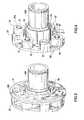
- FIG. 1is a cross-sectional view of the two speed transmission.
- FIG. 2is a cross-sectional view of the two speed transmission.
- FIG. 3is a perspective view of the planetary gear carrier.
- FIG. 4is a partial perspective view of the planetary gears on the carrier.
- FIG. 5is a partial perspective view of the planetary gear bearings and carrier bushings.
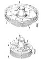
- FIG. 6is a partial perspective view of the carrier and output pulley.
- FIG. 7is a partial perspective view of the carrier and output pulley and input pulley.
- FIG. 8is a partial perspective view of the carrier brake shoe and output pulley.
- FIG. 9is a partial perspective view of the bearings and carrier brake shoe.
- FIG. 10is a perspective view of the transmission with the coil.
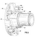
- FIG. 11is a cross-sectional view of the two speed transmission with an alternator connected to the transmission and coupled to the output shaft.
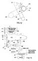
- FIG. 12is a schematic of a belt driven accessory drive.
- FIG. 13is a schematic of the inventive transmission used in a generator motor application.
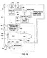
- FIG. 14is a schematic of the inventive transmission in an alternate generator motor arrangement.
- FIG. 1is a cross-sectional view of the two speed transmission.
- the two speed transmission 100is used on a belt driven accessory drive of the type used on vehicle internal combustion engines. It may also be used in any application where a two speed transmission is needed, for example, for driving industrial equipment or as a transmission on a 2, 3 or 4 wheeled vehicle.
- the transmission and associated control systemautomatically control an accessory speed based on engine speed in order to optimize engine fuel efficiency and available output drive torque at the drive wheels.
- the transmissionis very compact and can be mounted directly on an accessory, for example on a power steering pump, alternator or air conditioner compressor. In this arrangement the accessory is connected to an engine block.
- the two speed transmission 100comprises planetary gears disposed on an input carrier.
- the transmission input shaft and output shaftare coaxial.
- An electromagnetic brakeis used to control sun gear rotation and, thereby, output shaft speed.
- An endless power transmission beltis drivingly engaged between a driver pulley such as an engine crankshaft CR, see FIG. 12 , and a transmission input pulley 10 .
- the beltmay comprise a v-belt or multiple-ribbed belt, each known in the art.
- the beltmay be replaced by a by a chain or toothed belt each know in the art.
- Input pulley 10is connected to the input carrier using fasteners known in the art.
- the input carriercomprises input carrier portion 11 and input carrier portion 20 which is disposed opposite input carrier portion 11 , planetary gear members 15 , and input shaft 200 .
- a plurality of shafts 21interconnect between portion 11 and portion 20 .
- Each planetary gear member 15is journalled to a shaft 21 .
- Input carrier portion 20is connected to input shaft 200 .
- Labyrinth seal 26is connected to output pulley 30 .
- O-ring seal 25is disposed between shaft 19 and input carrier portion 11 .
- Each sealis known in the art and prevents debris from entering the planetary gear set.
- Ring gear 17 and sun gear 18each have a gear mesh engagement with planetary gears 15 .
- Sun gear 18is disposed on shaft 19 .
- Ring gear 17is disposed on the output pulley 30 .
- Shaft 19rotates concentrically about input shaft 200 and output shaft 31 .
- Planetary gears 15 , sun gear 18 and ring gear 17comprise straight cut gears. Use of straight cut gears negates the need for thrust bearings which might otherwise be needed with helical type gears. This significantly reduces the cost of the planetary gear train.
- Brake 40comprises a housing 52 , an electromagnetic coil 41 and an axially moveable brake shoe 190 for frictional rotation stopping engagement.
- Brake shoe 190 of shaft 19frictionally engages coil 41 when coil 41 is electrically activated, thereby stopping rotation of sun gear 18 .
- Input shaft 200is journalled to brake housing 52 on bearings 23 , 24 .
- Bearings 23 , 24comprise ball bearings known in the art and are used to provide a proper support for brake 40 .
- Other bearings known in the artmay also be used, for example, needle or cone bearings.
- Brake 40is electromagnetically actuated to engage and stop rotation of portion 190 and thereby shaft 19 and sun gear 18 based upon an engine speed signal. Brake 40 is either engaged (shaft 19 stopped) or disengaged (shaft 19 rotates). Brake 40 is engaged at engine idle and disengaged for engine speeds above idle. Power is provided to the brake 40 coil by wires 410 from a vehicle electrical system, and may either be 12V or 42V or some other desired voltage.
- Retainer clips 230 , 231 and 240retain bearings 23 , 24 in place on input shaft 200 .
- the clipsalso keep input shaft 200 properly spatially located with respect to brake housing 52 .
- Shaft 19is journalled to input shaft 200 on sleeve bearing 50 .
- a sleeve type bearingis sufficient for this service because the radial loads are minimal at idle when brake 40 is engaged, i.e., input shaft 200 is rotating and shaft 19 is locked up. At speeds greater than idle, brake 40 is disengaged and shaft 19 rotates in unison with input shaft 200 by operation of the one-way clutch 22 , i.e., there is no differential rotation between shafts 19 and 200 .
- Housing 52can be mounted to an engine block or other mounting surface using known fasteners such as bolts, screws or studs engaged through bosses 53 , 54 .
- One-way clutch 22is disposed between input shaft 200 and output shaft 31 .
- One-way, or sprag, clutch 22is of a type known in the art, for example, a model GFK 5904 available from Warner Electric/Formsprag.
- Planetary gears 15 , belt bearing surface 33 , bearing 50 , and one-way clutch 22are substantially coplanar in a radial direction with respect to an axis of rotation A-A. This arrangement has the benefit of minimizing or eliminating bending moments that might be imposed on the output portion of the transmission caused by a more axially staggered arrangement.
- End 32 of output shaft 31allows an accessory to be directly coaxially connected to the output shaft 31 .
- End 32can be used with any form of coupling known in the art, for example, keyed, keyless or splined.
- the accessoryis directly connected to housing 52 using known fasteners, for example, bolts or screws, see FIG. 11 .
- the accessorycan comprise an alternator, air conditioner compressor, power steering pump, fuel pump, oil pump or any other rotary accessory.
- the directly coupled accessoryis driven at the same speed as the output pulley 30 .
- Output pulley 30engages an endless power transmission belt which transmits torque to other belt driven accessories in a belt drive system, see FIG. 12 .
- a power transmission belt B 1 engaged with a driver such as a crankshaft pulley CRtransmits torque to input pulley 10 .
- the transmission output pulley 30then transmits torque through a second endless belt B 2 which is drivingly connected to other belt driven accessories.
- the transmissionoperates in one of two modes based upon engine speed.
- Brake statusis a function of engine speed, i.e., the output pulley speed is determined in part by whether the brake is engaged or disengaged.
- the transmission ratiois the ratio of the transmission planetary gear set only and is independent of the pulley ratios, including the pulley ratio between the output pulley and the accessory pulley, as well as the ratio between the crankshaft CR pulley and the input pulley 10 .
- a first operating mode brake 40is engaged when the engine is started or operating at an idle speed.
- the brakeis electrically engaged or disengaged by an engine speed signal provided by an engine control unit 500 .
- Unit 500may be formed as a computer system provided with known units including a CPU, a RAM, a ROM, a bi-directional communication bus, interface circuits (a signal conversion circuit and the like), and a memory.
- Unit 500receives an engine speed signal from an sensor or instrument such as a tachometer 600 , or other similar instrument for detecting rotational velocity known in the art such as a proximity detector.
- brake 40When the engine is shut off, brake 40 is not engaged. When a key is inserted to start the engine, brake 40 is activated before the starter starts the engine. However, to ease the engine start, brake 40 can be, activated slightly after the engine is running. In this case the one-way clutch drives the output shaft and the accessories are driven at a lower speed than required for idle, thereby minimizing the engine start power requirement. When the brake is disengaged the accessories are driven at a slower speed due to the pulley ratio between the output pulley 30 and an accessory pulley as described herein. The time delay between engine start and brake activation is approximately 0.5 to 1.0 seconds. After the time has elapsed brake 40 is engaged.
- the speed signal detected by an engine control unit 500generates a control signal.
- the control signalactivates the brake thereby stopping rotation of sun gear 18 .
- the engine speed at which brake 40 is activatedis selected based upon the nature of the engine and its desired operating characteristics.
- the engine idle speedis approximately 800 RPM.
- the transition speed at which the brake is engaged or disengagedis approximately 1200-1500 RPM so that the accessory speed does not drop significantly below a minimum desired speed at idle, thereby avoiding the situation where the accessory or accessories are driven too slowly, even if only momentarily.
- the second operating modeis when the engine is running at speeds greater than engine idle, for example at cruise or otherwise in excess of a pre-selected engine speed for example 1200-1500 RPM.
- brake 40is disengaged. With the brake disengaged, shaft 19 is unlocked and sun gear 18 rotates in unison with the input carrier.
- One-way clutch 22is engaged thereby driving output shaft 31 on a 1:1 basis with the input shaft 200 .
- the transmission ratiois only a part of the overall system by which the belt driven accessory drive speed is determined.
- the rotational speed of each accessoryis also individually determined in part by the diameter of the accessory pulley and its ratio with respect to the output pulley 30 . Therefore, the final belt driven accessory speed for a given engine speed is a function of the driver pulley (crankshaft) diameter, input pulley 10 diameter, transmission ratio, output pulley diameter 30 , and the accessory pulley diameter. Each of these variables are selected and combined to give the desired final drive ration and hence belt driven accessory speed.
- the final drive ratiodetermines the accessory speed for a given crankshaft (engine) speed.
- the inventive transmissioncan provide fuel savings on the order of up to approximately 5% compared to a comparable engine without the transmission.
- the inventive system at engine speeds greater than idledecreases the rotational speed of the accessories. This improves engine and vehicle performance, including improved acceleration times and increased power available at the drive wheels.
- the inventive systemhas the following operating characteristics.
- the final drive ratio in the 2.0 L engine example for the alternator at engine idleis approximately 2.33 (1866 RPM/800 RPM).
- the final drive ratio for the alternatoris approximately 1.48 (3705 RPM/2500 RPM).
- the inventive systemimparts a final drive ratio for a belt driven accessory that is inversely related to engine speed.
- the inverse relationship of a pulley drive ratio to engine speedalso applies to the accessory directly connected to and driven by the transmission, namely, the crankshaft pulley and the transmission input pulley.
- the inventive systemis given full reign when the brake 40 is disengaged and one-way clutch 22 is locked.
- the input 10 and output 30 pulleysrotate in unison. This combined with the accessory pulleys decreases the accessory rotational speed as compared to a prior art system. Reducing the accessory speed in this manner significantly increases overall fuel efficiency of the engine. It also increases torque available to the drive wheels.
- the pulley ratioscan be selected to accommodate any engine accessory drive configuration.
- the transmission ratiois also approximately 1.57.
- the idle speed in this exampleis approximately 650 RPM as compared to 800 RPM for the previous example.
- the final drive ratio in this example for the alternator at engine idleis approximately 3.26 (2121.6 RPM/650 RPM).
- the final drive ratio for the alternatoris approximately 2.07 (3110 RPM/1500 RPM).
- the directly connected accessory speed at engine idlecorresponds to the pulley ratio between the crankshaft pulley and the input pulley 10 as modified by the transmission ratio.
- the directly connected accessory speedcorresponds to the pulley ratio between the crankshaft pulley and the input pulley 10 .
- At engine speeds above idlethere is no additional effect due to the transmission ratio since the planetary gears are not operable and all rotation of the output shaft is caused by the one-way clutch 22 .
- the duty cycle for the transmission in the inventive systemis approximately 5%, meaning the transmission is in operation (that is, brake engaged) approximately 5% of the time, basically when the engine is at idle.
- the duty cycleis dependent on the engine operating conditions and is preferably in the range of approximately 4% to 10% and may be as high as approximately 25% or 30%.
- the prior art systemshave a reciprocal duty cycle ( ⁇ 95%) since they operate a transmission when the engine is operated at speeds greater than idle.
- a low duty cycleis desirable because it extends the operating life of the transmission.
- idleis used for ease of reference and is not intended to signify limiting the invention to particular engine speed. Idle speed can and does differ among various vehicles and engine types.
- the systemallows multiple accessories to be driven at two different speeds for any range of engine speeds.
- This first available accessory speedbeing that of the accessory which is directly connected to the output shaft 31 .
- the second accessory speedbeing that of the belt driven accessory as further determined by the transmission ratio and respective pulley ratio of the transmission output pulley 30 and a particular driven accessory pulley.
- the accessoriescan be selected and located in a belt drive system to optimize the beneficial effect of two available operational speeds.
- the air conditioner or alternatorcan be directly connected to the transmission output shaft ( 32 ) while other belt driven accessories, such as a power steering pump or water pump, are driven at a different speed by a second belt from the output pulley 30 .
- the innovative compact designis realized by disposing the planetary gear train fully within the width (W) of the belt bearing portion 33 of the output pulley 30 .
- Brake shoe 190 for the sun gear 18is compactly disposed adjacent the input pulley 10 .
- the overall thickness of the transmissionis substantially a function of the width of the pulley 10 , pulley 30 and the width of brake 40 .
- brake 40can be fully contained within a width (W 2 ) of input pulley 10 .
- the overall thickness of the transmissionhas a lower limit substantially bounded by the width of the input and output pulley in the closest possible proximity. For example, this can represent an overall end-to-end transmission thickness as small as approximately 45 mm.
- the inventive transmissionallows a significant increase in fuel efficiency while only requiring an extra clearance space on the order of approximately 30 mm, and in certain cases less than 20 mm is required based on the overall width of an output belt B 2 .
- FIG. 2is a cross-sectional view of the two speed transmission.
- Input carrier portion 11 and input carrier portion 20are connected together with members 27 by fasteners 201 .
- Members 27are circumferentially disposed about the input carrier, see FIG. 4 .
- Input pulley 10 , input carrier portion 11 , input carrier portion 20 and input shaft 200comprise an input rotating assembly.
- planetary gears 15are journalled to the input carrier shafts 21 .
- FIG. 3is a perspective view of the planetary gear carrier. Planetary gears 15 are disposed circumferentially about the carrier alternately interposed between members 27 . Fasteners 201 connect portion 11 to members 27 .
- FIG. 4is a partial perspective view of the planetary gears on the carrier.
- Each planetary gear 15is journalled to a shaft 21 on a bearing 210 known in the art, such as a needle bearing or sleeve bearing.
- the bearing selectionis dependent on the service conditions.
- FIG. 5is a partial perspective view of the planetary gear bearings and carrier sleeve bearing.
- Each planetary gear bearing 210is disposed between a planetary gear 15 and a shaft 21 .
- Carrier sleeve bearing 50is disposed between input shaft 200 and output shaft 31 .
- FIG. 6is a partial perspective view of the carrier and output pulley.
- the compact design of the transmissionallows the planetary gear carrier to be fully contained within a width of the output pulley.
- Input shaft 200comprises a bore 202 in which output shaft 31 is disposed.
- FIG. 7is a partial perspective view of the carrier and output pulley and input pulley.
- Fasteners 12attach input pulley 10 to input carrier portion 11 .
- Input pulley 10may also be attached to input carrier portion 11 by tack welding or any other suitable connecting means known in the art.
- FIG. 8is a partial perspective view of the carrier brake shoe and output pulley.
- Brake shoe 190comprises a radially extending surface which frictionally engages coil 41 upon activation of said coil. Engagement of shoe 190 with coil 41 stops rotation of the sun gear 18 . Brake shoe 190 is substantially contained within a width of input pulley 10 .
- FIG. 9is a partial perspective view of the bearings and carrier brake shoe. Bearings 23 , 24 support input shaft 200 on brake housing 52 .
- FIG. 10is a perspective view of the transmission with the coil.
- Brake 40axially locates and supports input shaft 200 on bearings 23 , 24 .
- Bosses 53 , 54are used with fasteners to connect the transmission to a mounting surface.
- FIG. 11is a cross-sectional view of the two speed transmission connected to an alternator 700 .
- Alternator 700is directly coupled to the output shaft 31 .
- Alternator 700is simply used as an example as any other accessory may be directly connected to the transmission as well.
- Direct couplingis accomplished by use of splines 703 on shaft 31 , although any form of shaft coupling suitable for the service and known in the art is acceptable.
- Tabs 702extend from the transmission and alternator. Fasteners 701 connect tabs 702 . Fasteners 701 comprise screws, bolts or studs for example. Alternator 700 is electrically connected to a vehicle electrical system in a manner known in the art.
- FIG. 12is a schematic of a belt driven accessory drive.
- Belt B 1is drivingly engaged between a crankshaft pulley CR and input pulley 10 .
- Belt B 2is drivingly engaged between output pulley 30 and accessory pulleys A 2 and A 3 .
- Belt B 1 and B 2each comprise a multiple ribbed profile, see FIG. 2 .
- An accessory Alis directly coupled to the transmission 100 .
- Accessory Almay comprise an alternator 700 .
- a belt tensioner Timposes a tension on belt B 2 .
- Tensioner Tmay comprise any tensioner known in the art, including an asymmetric tensioner, Zed type, or linear tensioner.
- the asymmetric tensionercomprises a pulley pivotally mounted to a tensioner arm.
- the asymmetric tensionercomprises a damping mechanism that has a damping force which is greater in a first direction than in a second direction.
- either belt, B 1 or B 2 or both, used in the inventive systemcomprises a low modulus belt known in the art.
- the low modulus beltcomprises a belt having a tensile cord comprising nylon 4.6 or nylon 6.6 or a combination of the two.
- An elastic modulus of the beltis in the range of approximately 1500 N/mm to approximately 3000 N/mm.
- a feature of the low modulus beltis that it can be installed on a belt drive system without a tensioner or moveable shaft accessory.
- the low modulus beltis simply installed using a belt installation tool known in the art. The tool is used to roll or laterally urge the belt over an edge of a transmission pulley or accessory pulley without the need to otherwise adjust the center location of the pulley shaft.
- the low modulus beltis particularly suitable for belt B 1 since equipping the transmission in such a way that it would otherwise be movable to allow installation and adjustment of belt B 1 might be more expensive than simply designing the transmission to be directly connected to an engine mounting surface such as an engine block. Further, adjusting the transmission shaft location with respect to the crankshaft would consume more assembly time as well.
- chainsmay be used in place of the belts.
- transmission 100 and one or all of the accessoriesmay also be provided with adjustable mounting means known in the art which allows the shaft location to be adjusted during installation.
- FIG. 13is a schematic of the inventive transmission used in a generator motor application.
- Automatic transmission (“A/T”) 2is disposed adjacent to the engine (“E/G”) 1 .
- Motor generator 300 (“M/G”)serves as a motor and an electric generator.
- Engine crank shaft 3 , and shaft 31 and shaft 200 of the M/G 300are disposed in parallel with each other.
- M/G 300is directly connected to transmission 100 as described elsewhere in this specification.
- Transmission 100is mechanically disposed between the M/G 300 and the crank shaft 3 so that the rotational speed of shaft 200 is reduced and transmitted to crank shaft 3 .
- Pulley CRis connected to the crank shaft 3 .
- Pulley 10is connected to transmission 100 as described in this specification.
- Belt B 1is set between pulley CR and pulley 10 .
- Pulley 30is directly connected to shaft 31 of the M/G 300 .
- Pulley 10is operatively connected to shaft 200 by the planetary gear set.
- Pump P for a power steering unit and a compressor A/C for an air conditionerare each an accessory included in the engine belt drive system.
- Pulleys A 2 and A 3are secured to the respective ends of the rotational shafts of the pump P and the compressor A/C.
- a belt B 2is engaged among the pulleys 30 , A 2 , and A 3 .
- the pulleys 30 , A 2 , A 3 and the belt B 2constitute a power transmission means for transmitting rotation of M/G 300 to the respective accessories.
- An inverter 400is electrically connected to M/G 300 and arranged to vary the amount of electric energy to be supplied from a battery 800 to the M/G 300 to control the speed of M/G 300 when M/G 300 is used in a motor mode. Inverter 400 also performs control to store electric energy generated by M/G 300 to battery 800 .
- M/G 300is connected to an oil pump 194 for the A/T through electromagnetic clutch 191 .
- An oil inlet pipe 192is connected to the oil pump 194 .
- An oil outlet pipe 193is connected to the oil pump 194 .
- Oil pimp 194is connected to an engine lubrication system (not shown).
- the foregoing structureenables M/G 300 to operate the oil pump 194 by engaging electromagnetic clutch 191 while the engine is stopped. This is because the starting clutch (not shown) disposed in the A/T is arranged to be immediately engaged for driving the vehicle smoothly upon re-start of the engine.
- controller 500transmits to inverter 400 a signal for controlling the engine running mode switching operation, ON-OFF control signals to the electromagnetic clutch 191 and ON-OFF control signals to the electromagnetic coil 41 of the transmission. Controller 500 also receives signals from various sensors disposed on the vehicle and on the engine that are indicative of a vehicle operating condition and/or of an engine operating condition.
- a signal indicating the speed of M/G 300includes a signal indicating the speed of M/G 300 , a signal for switching the engine running mode, a signal for switching the operation of the air conditioner, an engine status signal indicating, for example, the speed of the engine 1 , a vehicle status signal (not shown) indicating the vehicle speed and the like, a wheel brake status signal, an engine throttle position signal, and a status signal of the A/T indicating the range selected by the shift lever.
- the brake status signalindicates the state of engagement of each wheel brake or all wheel brakes on the vehicle.
- the throttle position signalrelates to the position of the throttle, which is indicative of the driver demand to the engine such as acceleration, deceleration, non-accelerating cruise or idle. Each signal may be either analogue or digital.
- controller 500performs an operation for reading data from a memory 900 and a calculating operation to determine an engine first running mode (engine operating) or a second running mode (engine not operating). Then controller 500 transmits control signals to the transmission brake coil 41 , the inverter 400 , and electromagnetic clutch 191 .
- Controller 500may be formed as a computer system provided with known units including a CPU, a RAM, a ROM, a bi-directional communication bus, interface circuits (a signal conversion circuit and the like), and a memory 900 .
- M/G 300is operated to start the engine 1 .
- M/G 300acts as a power generator for storing electric energy in the battery 800 .
- the controller 500detects the speed of M/G 300 .
- controller 500causes inverter 400 to perform a switching operation such that a torque and speed required to start the engine 1 are realized. For example, if a signal for switching the air conditioner A/C has been turned ON at engine start, a higher torque is required compared with the OFF state of the A/C. Therefore, controller 500 applies to inverter 400 a switching control signal to allow M/G 300 to rotate at a higher torque with a greater speed.
- the switching control signalmay be determined such that a variety of status signals of the engine 1 , the A/T 2 and the vehicle are provided to the controller 500 and thereby collated with a map memory stored in the memory.
- the switching control signalmay be determined by calculations performed by the processor unit (CPU) disposed in controller 500 .
- controller 500stops the engine 1 by transmitting a signal for interrupting fuel supply to the engine 1 for example to an electric fuel pump (not shown).
- the engine stop operationcan be performed under a condition where, for example, the vehicle speed is zero, the brakes are partially or fully applied, and the shift lever is in the D or N setting. Thus, no power is transmitted between the pulley 10 and the engine 1 .
- electromagnetic clutch 191can be brought to a connected state to allow M/G 300 to operate the oil pump 194 while engine 1 is off. This is because the starting clutch (not shown) disposed in the A/T 2 is arranged to be immediately engaged for driving the vehicle smoothly upon re-starting of the engine.
- controller 500applies to inverter 400 a switching control signal to rotate the M/G 300 at the speed and torque corresponding to the loads of the pump P for a power steering unit, the compressor A/C for the air conditioner and the oil pump 190 for the A/T 2 .
- brake 41is OFF or disengaged.
- M/G 300in motor mode cranks engine 1 when brake coil 41 is turned ON thereby stopping rotation of sun gear 18 .
- Brake coil 41is energized causing pulley 10 to rotate at a predetermined speed and torque.
- the rotational force of M/G 300is transmitted at a decreased speed from the ring gear 17 to the carrier 11 and thereby to pulley 10 and thereby to crankshaft pulley CR.
- M/G 300When the M/G 300 is used as an electric generator, and/or the accessories are operated while engine 1 is operating in a first running mode, brake coil 41 is turned OFF and one-way clutch 22 is in an engaged state.
- M/G 300 and the pulley 10are rotationally connected with each other so that the rotations of pulley 10 are transmitted through clutch 22 to the M/G 300 via shaft 31 .
- Transmission 100is operating in part as a clutch to control transmission of torque to the engine, or to receive torque from the engine depending on the mode selected.
- FIG. 14is a schematic of the inventive transmission in an alternate generator motor arrangement. Generally, the components and their relationship in this alternate embodiment are as described in FIG. 13 , with the differences described herein.
- M/G 300is not directly attached to transmission 100 .
- Transmission 100has no directly connected accessory.
- M/G 300is connected to transmission 100 by belt B 2 .
- Torqueis transmitted to and from transmission 100 by belt B 1 and B 2 between engine 1 , M/G 300 and the accessories.
- Transmission 100is directly mounted to engine 1 using fasteners such as bolt or screws.
- This embodimentillustrates that the M/G can be connected, either directly or by belt, to either end of transmission output shaft 31 .
- Thisprovides alternate belt drive arrangements in which the inventive transmission can be successfully used.
- M/G 300in motor mode cranks engine 1 through belt B 2 , transmission 100 , and belt B 1 when brake coil 41 is turned ON, thereby engaging the brake and stopping rotation of sun gear 18 .
- Energizing brake coil 41causes pulley 10 to rotate at a predetermined speed and torque.
- the rotational force of M/G 300is transmitted at a decreased speed through belt B 2 , to pulley 30 to ring gear 17 to the carrier 11 and thereby to pulley 10 and thereby to crankshaft pulley CR through belt B 1 .
- Due to the configuration of belt B 2accessories P and A/C are rotated while the M/G 300 is operating in motor mode during engine start as well.
- an accessory 1000may be directly coupled to transmission 100 as described in FIG. 11 .
- Accessory 1000may comprise a fuel pump, oil pump or any other accessory as may be required by an engine or vehicle.
- accessory 1000is directly connected to transmission 100 and to shaft 31 . Due to the unique arrangement of coaxial shafts 31 , 200 of transmission 100 , accessory 1000 is fully operable by M/G 300 along with the other accessories even when engine 1 is not operating and M/G 300 is in motor mode. Of course, accessory 1000 is also driven by engine 1 along with accessories P and A/C when engine 1 is operating and M/G 300 is operated as a generator.
Landscapes
- Engineering & Computer Science (AREA)
- Combustion & Propulsion (AREA)
- Transportation (AREA)
- Mechanical Engineering (AREA)
- Chemical & Material Sciences (AREA)
- Power Engineering (AREA)
- Devices For Conveying Motion By Means Of Endless Flexible Members (AREA)
- Structure Of Transmissions (AREA)
- Transmission Devices (AREA)
- Auxiliary Drives, Propulsion Controls, And Safety Devices (AREA)
- Arrangement Of Transmissions (AREA)
- Transmissions By Endless Flexible Members (AREA)
- Control Of Transmission Device (AREA)
- Pulleys (AREA)
- General Details Of Gearings (AREA)
Abstract
Description
| 2.0 L Engine (Comparison: Original (Prior Art) and Transmission) |
| Pulley | Accessory Speeds | Accessory Speeds | |
| Diameters (mm) | (RPM) - “Idle” | (RPM) - “Off Idle” |
| Two | Two | Two | |||||
| Original | Speed | Original | Speed | Original | Speed | ||
| Drive | Module | Drive | Module | Drive | Module | ||
| Crank | 134.01 | 111.98 | 800 | 800 | 2500 | 2500 |
| AC | 146.01 | N/A | 734 | 734 | 2295 | 1458 |
| PS | 139.51 | 138.03 | 767 | 767 | 2402 | 1536 |
| Alt | 56.86 | 56.86 | 1866 | 1866 | 5833 | 3705 |
| WP | 107.50 | 106.38 | 998 | 998 | 3118 | 1981 |
| Input | N/A | 192.00 | N/A | 467 | N/A | 1458 |
| Output | N/A | 144.50 | N/A | 734 | N/A | 1458 |
| 5.3 L Engine (Comparison: Original (Prior Art) and Transmission) |
| Pulley Diameters | Accessory Speeds | Accessory Speeds | |
| (mm) | (RPM) - “Idle” | (RPM) - “Off Idle” |
| Two | Two | Two | |||||
| Original | Speed | Original | Speed | Original | Speed | ||
| Drive | Module | Drive | Module | Drive | Module | ||
| Crank | 193.57 | 193.57 | 650 | 650 | 1500 | 1500 |
| AC | 111.9 | N/A | 1124.5 | 1124.5 | 2595 | 1648 |
| PS | 163.6 | 187.19 | 769 | 769 | 1775 | 1127 |
| Alt | 59.31 | 67.8 | 2121.6 | 2121.6 | 4896 | 3110 |
| WP | 150.8 | 172.46 | 834.6 | 834.6 | 1926 | 1223 |
| Input | N/A | 176.13 | N/A | 714.4 | N/A | 1648 |
| Output | N/A | 128 | N/A | 1124.5 | N/A | 1648 |
Claims (3)
Priority Applications (1)
| Application Number | Priority Date | Filing Date | Title |
|---|---|---|---|
| US11/809,136US7727115B2 (en) | 2004-01-13 | 2007-05-31 | Two speed transmission and belt drive system |
Applications Claiming Priority (2)
| Application Number | Priority Date | Filing Date | Title |
|---|---|---|---|
| US10/756,079US7316628B2 (en) | 2004-01-13 | 2004-01-13 | Two speed transmission and belt drive system |
| US11/809,136US7727115B2 (en) | 2004-01-13 | 2007-05-31 | Two speed transmission and belt drive system |
Related Parent Applications (1)
| Application Number | Title | Priority Date | Filing Date |
|---|---|---|---|
| US10/756,079DivisionUS7316628B2 (en) | 2004-01-13 | 2004-01-13 | Two speed transmission and belt drive system |
Publications (2)
| Publication Number | Publication Date |
|---|---|
| US20070232435A1 US20070232435A1 (en) | 2007-10-04 |
| US7727115B2true US7727115B2 (en) | 2010-06-01 |
Family
ID=34739750
Family Applications (2)
| Application Number | Title | Priority Date | Filing Date |
|---|---|---|---|
| US10/756,079Expired - LifetimeUS7316628B2 (en) | 2004-01-13 | 2004-01-13 | Two speed transmission and belt drive system |
| US11/809,136Expired - LifetimeUS7727115B2 (en) | 2004-01-13 | 2007-05-31 | Two speed transmission and belt drive system |
Family Applications Before (1)
| Application Number | Title | Priority Date | Filing Date |
|---|---|---|---|
| US10/756,079Expired - LifetimeUS7316628B2 (en) | 2004-01-13 | 2004-01-13 | Two speed transmission and belt drive system |
Country Status (12)
| Country | Link |
|---|---|
| US (2) | US7316628B2 (en) |
| EP (1) | EP1711992B1 (en) |
| JP (3) | JP4649417B2 (en) |
| KR (2) | KR20080002973A (en) |
| CN (2) | CN100471714C (en) |
| AT (1) | ATE449452T1 (en) |
| AU (1) | AU2004314557B2 (en) |
| BR (1) | BRPI0418398B1 (en) |
| CA (2) | CA2697890C (en) |
| DE (1) | DE602004024241D1 (en) |
| RU (1) | RU2335839C2 (en) |
| WO (1) | WO2005071819A1 (en) |
Cited By (51)
| Publication number | Priority date | Publication date | Assignee | Title |
|---|---|---|---|---|
| US20080039272A1 (en)* | 2004-10-05 | 2008-02-14 | Fallbrook Technologies Inc. | Continuously variable transmission |
| US20080195267A1 (en)* | 2005-03-01 | 2008-08-14 | Peugeot Citroen Automobiles Sa | Method For Starting On An Up Slope Or With A High Load |
| US20080261771A1 (en)* | 2005-12-09 | 2008-10-23 | Fallbrook Technologies Inc. | Continuously variable transmission |
| US20090026035A1 (en)* | 2007-03-10 | 2009-01-29 | Piercarlo Boffelli | Hybrid Apparatus for Transmitting Motive Power to a Driven Shaft |
| US20090298646A1 (en)* | 2008-05-27 | 2009-12-03 | Scott Parsons | Engine powered device having accessory drive and reversing motor for selectively starting engine and powering accessory drive |
| US20090312145A1 (en)* | 2006-06-26 | 2009-12-17 | Fallbrook Technologies Inc. | Continuously variable transmission |
| US20090314559A1 (en)* | 2005-04-29 | 2009-12-24 | Prototipo S.P.A. | Engine unit with start-stop control for a motor vehicle |
| US20100093485A1 (en)* | 2006-11-08 | 2010-04-15 | Fallbrook Technologies Inc. | Clamping force generator |
| US20100093480A1 (en)* | 2008-10-14 | 2010-04-15 | Fallbrook Technologies Inc. | Continuously variable transmission |
| US20100193268A1 (en)* | 2009-02-05 | 2010-08-05 | Gm Global Technology Operations, Inc. | Hybrid vehicle drive system |
| US20100267510A1 (en)* | 2009-04-16 | 2010-10-21 | Fallbrook Technologies Inc. | Continuously variable transmission |
| US8087482B2 (en) | 2006-03-14 | 2012-01-03 | Fallbrook Technologies Inc. | Wheelchair |
| US20120068651A1 (en)* | 2009-07-17 | 2012-03-22 | Schaeffler Technologies Gmbh & Co. Kg | Generator drive system for an internal combustion engine |
| US8267829B2 (en) | 2003-02-28 | 2012-09-18 | Fallbrook Intellectual Property Company Llc | Continuously variable transmission |
| US8313404B2 (en) | 2007-02-16 | 2012-11-20 | Fallbrook Intellectual Property Company Llc | Infinitely variable transmissions, continuously variable transmissions, methods, assemblies, subassemblies, and components therefor |
| US8313405B2 (en) | 2008-02-29 | 2012-11-20 | Fallbrook Intellectual Property Company Llc | Continuously and/or infinitely variable transmissions and methods therefor |
| US20120291740A1 (en)* | 2010-02-09 | 2012-11-22 | Peugeot Citroen Automobiles Sa | Coupling Device Between A Shaft And A Pulley And Engine Block Suitable For Being Installed In A Motor Vehicle |
| US8321097B2 (en) | 2007-12-21 | 2012-11-27 | Fallbrook Intellectual Property Company Llc | Automatic transmissions and methods therefor |
| US8317651B2 (en) | 2008-05-07 | 2012-11-27 | Fallbrook Intellectual Property Company Llc | Assemblies and methods for clamping force generation |
| US8342999B2 (en) | 2005-10-28 | 2013-01-01 | Fallbrook Intellectual Property Company Llc | Electromotive drives |
| US8393989B2 (en) | 2007-04-24 | 2013-03-12 | Fallbrook Intellectual Property Company Llc | Electric traction drives |
| US8398518B2 (en) | 2008-06-23 | 2013-03-19 | Fallbrook Intellectual Property Company Llc | Continuously variable transmission |
| US8469856B2 (en) | 2008-08-26 | 2013-06-25 | Fallbrook Intellectual Property Company Llc | Continuously variable transmission |
| US8506452B2 (en) | 2005-12-30 | 2013-08-13 | Fallbrook Intellectual Property Company Llc | Continuously variable transmission |
| US8512195B2 (en) | 2010-03-03 | 2013-08-20 | Fallbrook Intellectual Property Company Llc | Infinitely variable transmissions, continuously variable transmissions, methods, assemblies, subassemblies, and components therefor |
| US8535199B2 (en) | 2008-06-06 | 2013-09-17 | Fallbrook Intellectual Property Company Llc | Infinitely variable transmissions, continuously variable transmissions, methods, assemblies, subassemblies, and components therefor |
| US20130343908A1 (en)* | 2008-10-31 | 2013-12-26 | Knorr-Bremse Systeme Fuer Nutzfahrzeuge Gmbh | Clutch Compressor and Power Steering Pump Arrangement, and Method for Controlling the Same |
| US8641577B2 (en) | 2007-06-11 | 2014-02-04 | Fallbrook Intellectual Property Company Llc | Continuously variable transmission |
| US8708360B2 (en) | 2005-11-22 | 2014-04-29 | Fallbrook Intellectual Property Company Llc | Continuously variable transmission |
| US8738255B2 (en) | 2007-02-01 | 2014-05-27 | Fallbrook Intellectual Property Company Llc | Systems and methods for control of transmission and/or prime mover |
| US8776633B2 (en) | 2006-01-30 | 2014-07-15 | Fallbrook Intellectual Property Company Llc | System for manipulating a continuously variable transmission |
| US8818661B2 (en) | 2008-08-05 | 2014-08-26 | Fallbrook Intellectual Property Company Llc | Methods for control of transmission and prime mover |
| US8845485B2 (en) | 2011-04-04 | 2014-09-30 | Fallbrook Intellectual Property Company Llc | Auxiliary power unit having a continuously variable transmission |
| US8888643B2 (en) | 2010-11-10 | 2014-11-18 | Fallbrook Intellectual Property Company Llc | Continuously variable transmission |
| US8900085B2 (en) | 2007-07-05 | 2014-12-02 | Fallbrook Intellectual Property Company Llc | Continuously variable transmission |
| US8996263B2 (en) | 2007-11-16 | 2015-03-31 | Fallbrook Intellectual Property Company Llc | Controller for variable transmission |
| US9371894B2 (en) | 2007-02-12 | 2016-06-21 | Fallbrook Intellectual Property Company Llc | Continuously variable transmissions and methods therefor |
| US9611921B2 (en) | 2012-01-23 | 2017-04-04 | Fallbrook Intellectual Property Company Llc | Infinitely variable transmissions, continuously variable transmissions, methods, assemblies, subassemblies, and components therefor |
| US9677650B2 (en) | 2013-04-19 | 2017-06-13 | Fallbrook Intellectual Property Company Llc | Continuously variable transmission |
| US10047861B2 (en) | 2016-01-15 | 2018-08-14 | Fallbrook Intellectual Property Company Llc | Systems and methods for controlling rollback in continuously variable transmissions |
| WO2018227310A1 (en)* | 2017-06-16 | 2018-12-20 | Litens Automotive Partnership | Drive arrangement permitting driving of a vehicle by an electric motor |
| US10458526B2 (en) | 2016-03-18 | 2019-10-29 | Fallbrook Intellectual Property Company Llc | Continuously variable transmissions, systems and methods |
| US10676079B1 (en)* | 2018-12-06 | 2020-06-09 | GM Global Technology Operations LLC | Hybrid electric powertrian system with e-accessory drive and associated power sharing architecture |
| US10830126B2 (en)* | 2018-06-29 | 2020-11-10 | Schaeffler Technologies AG & Co. KG | Two-speed accessory drive pulley |
| US11174922B2 (en) | 2019-02-26 | 2021-11-16 | Fallbrook Intellectual Property Company Llc | Reversible variable drives and systems and methods for control in forward and reverse directions |
| US11215268B2 (en) | 2018-11-06 | 2022-01-04 | Fallbrook Intellectual Property Company Llc | Continuously variable transmissions, synchronous shifting, twin countershafts and methods for control of same |
| US20220056989A1 (en)* | 2020-08-18 | 2022-02-24 | Illinois Tool Works Inc. | Keyless Coupling Arrangement for a Generator and Associated Methods |
| US11566561B2 (en)* | 2020-08-17 | 2023-01-31 | Ford Global Technologies, Llc | Front end accessory drive with multiple speed ratios |
| US11667351B2 (en) | 2016-05-11 | 2023-06-06 | Fallbrook Intellectual Property Company Llc | Systems and methods for automatic configuration and automatic calibration of continuously variable transmissions and bicycles having continuously variable transmission |
| US11939910B2 (en)* | 2020-08-18 | 2024-03-26 | Illinois Tool Works Inc. | Belt drive system having an intermediate generator and associated method |
| US12442434B2 (en) | 2024-06-04 | 2025-10-14 | Enviolo B.V. | Reversible variable drives and systems and methods for control in forward and reverse directions |
Families Citing this family (59)
| Publication number | Priority date | Publication date | Assignee | Title |
|---|---|---|---|---|
| US7086981B2 (en)* | 2004-02-18 | 2006-08-08 | The Gates Corporation | Transmission and constant speed accessory drive |
| DE202005018560U1 (en)* | 2005-11-25 | 2006-02-23 | Power Hybrid Deutschland Gmbh | Conversion kit for saving fuel in passenger cars |
| US20070137197A1 (en)* | 2005-12-21 | 2007-06-21 | David Turner | Engine supercharging system |
| US20070261902A1 (en)* | 2006-05-15 | 2007-11-15 | George Margoudakis | Electric motor vehicle |
| CN101106319B (en)* | 2006-07-11 | 2011-01-19 | 巩长勇 | Magnetic canister drive speed-adjusting clutch |
| EP1903259A3 (en)* | 2006-09-20 | 2009-09-02 | Baruffaldi S.p.A. | Electromagnetic device for actuating a member for locking a rotating body, for example in a differential |
| US20080096711A1 (en)* | 2006-10-23 | 2008-04-24 | Gm Global Technology Operations, Inc. | Variable speed accessory drive system |
| ITMI20070438A1 (en)* | 2007-03-05 | 2008-09-06 | Baruffaldi Spa | MAGNETIC REPULSION JOINT FOR THE TRANSMISSION OF A ROTATION MOTION FROM A MOTOR ELEMENT TO A CONDUIT ELEMENT |
| DE102007021195A1 (en) | 2007-05-05 | 2008-11-06 | Schaeffler Kg | Traction drive for drive arrangement of e.g. dynamo machine, of motor vehicle, has freewheel clutches or centrifugal clutches, which are coaxially arranged respectively between belt pulleys and drive shaft |
| US7765805B2 (en)* | 2007-07-24 | 2010-08-03 | Kasi Forvaltning I Goteborg Ab | Enhanced supercharging system and an internal combustion engine having such a system |
| US20090266097A1 (en)* | 2007-11-14 | 2009-10-29 | David Hamilton | Mechanism for maintaining a desired temperature in a truck cab including an auxiliary motor for operating a vehicle air conditioning pump as well as a secondary generator for providing either power when the vehicle is parked or a convective heat transfer via a fluid jacket communicating with a vehicle mounted convective heat transfer network |
| DE102007055543A1 (en)* | 2007-11-21 | 2009-05-28 | Schaeffler Kg | Running disk, tensioning and / or deflection roller as well as V-ribbed belt drive |
| EP2549139B1 (en)* | 2008-04-04 | 2014-03-12 | Litens Automotive Partnership | Auto-selecting two-ratio transmission |
| FR2930198A1 (en)* | 2008-04-17 | 2009-10-23 | Renault Sas | Vehicle i.e. semi-hybrid vehicle, has variable transmission ratio driving unit modifying transmission ratio in operating modes when alterno-starter operates as alternator and operates as starter, respectively |
| DE102008023177B4 (en)* | 2008-05-10 | 2019-06-27 | Dr. Ing. H.C. F. Porsche Aktiengesellschaft | Drive device for at least one auxiliary machine unit by means of a belt |
| JP4707072B2 (en)* | 2008-05-23 | 2011-06-22 | 本田技研工業株式会社 | Power transmission device for vehicle |
| DE102008033177A1 (en)* | 2008-07-15 | 2010-01-21 | Volkswagen Ag | Adjustable compressor, particularly for use in refrigerant circuit of air conditioning vehicle, has belt pulley rotatably mounted on drive shaft for drive belt, where gear is arranged in belt pulley |
| DE102008041067A1 (en)* | 2008-08-07 | 2010-02-11 | Robert Bosch Gmbh | Pressure pump device for a hybrid vehicle |
| US8313400B2 (en)* | 2008-11-13 | 2012-11-20 | The Gates Corporation | Damped isolator |
| US8137229B2 (en)* | 2008-11-20 | 2012-03-20 | GM Global Technology Operations LLC | Modular transmission assembly and a method of assembly |
| JP5420234B2 (en)* | 2008-12-08 | 2014-02-19 | 現代自動車株式会社 | V-belt drive type motor generator device |
| CN101839312B (en)* | 2009-03-19 | 2013-01-02 | 本田技研工业株式会社 | Vehicular automatic transmission with planetary gear mechanism |
| JP5550043B2 (en)* | 2009-04-23 | 2014-07-16 | シンフォニアマイクロテック株式会社 | Electromagnetic clutch |
| GB2469872A (en)* | 2009-05-01 | 2010-11-03 | Antonov Plc | A transmission unit for relaying drive from a cranksgaft of an internal combustion engine to engine ancillaries |
| US8500590B2 (en)* | 2010-06-23 | 2013-08-06 | Borgwarner, Inc. | Electromagnetic clutch disconnect for accessory drive |
| RU2478487C2 (en)* | 2010-10-14 | 2013-04-10 | Российская Федерация, От Имени Которой Выступает Министерство Промышленности И Торговли Российской Федерации | Transport facility combined power plant |
| DE102011086059A1 (en)* | 2010-12-09 | 2012-06-14 | Schaeffler Technologies Gmbh & Co. Kg | Crankshaft pulley |
| DE112012001651T5 (en)* | 2011-04-11 | 2014-03-06 | Litens Automotive Partnership | Multi-speed drive for transmitting power to a load |
| CN102821561A (en)* | 2011-06-08 | 2012-12-12 | 鸿富锦精密工业(深圳)有限公司 | Container data center |
| JP5762202B2 (en)* | 2011-08-02 | 2015-08-12 | 日立オートモティブシステムズ株式会社 | Variable displacement vane pump |
| US9279325B2 (en) | 2012-11-08 | 2016-03-08 | General Electric Company | Turbomachine wheel assembly having slotted flanges |
| CN103343804B (en)* | 2013-07-22 | 2016-08-10 | 段鹏飞 | A kind of belt wheel for belt composite transmission system |
| FR3011779B1 (en)* | 2013-10-10 | 2017-02-10 | Technoboost | MOTOR POWERTRAIN HAVING ROTATING MACHINES CONNECTED BY A CLUTCH TO A PRIMARY SHAFT OF THE GEARBOX |
| US10343491B2 (en)* | 2015-12-17 | 2019-07-09 | Nissan North America, Inc. | Vehicle accessory power management assembly |
| CN106965671A (en)* | 2016-10-27 | 2017-07-21 | 蔚来汽车有限公司 | Two-gear transmission power assembly for pure electric vehicle |
| US10161374B2 (en)* | 2017-01-11 | 2018-12-25 | Gates Corporation | Accessory belt drive system with multiple ratios and torque reversal |
| CN108134200B (en)* | 2017-12-22 | 2022-01-18 | 东莞市本量电子科技有限公司 | Built-in dual-motor six-gear-shifting electrically-tunable antenna driver |
| US11187306B2 (en)* | 2018-03-28 | 2021-11-30 | Schaeffler Technologies AG & Co. KG | Two-speed accessory drive pulley |
| DE102018207590B4 (en)* | 2018-05-16 | 2023-09-07 | Magna Pt B.V. & Co. Kg | Drive system with electromagnetic shift actuator and method for controlling the same |
| WO2019224787A2 (en)* | 2018-05-23 | 2019-11-28 | Cummins Inc. | System and method for a captive sprocket in an engine |
| US11441481B2 (en)* | 2018-05-24 | 2022-09-13 | Ford Global Technologies, Llc | Mechanism for a two-speed engine accessory drive system in a vehicle |
| CN110118124B (en)* | 2019-05-24 | 2020-09-29 | 潍柴动力股份有限公司 | A kind of engine gear train and engine gear train control method |
| US11637478B2 (en)* | 2019-07-19 | 2023-04-25 | Hanon Systems EFP Canada Ltd. | Pulley assisted electromagnetic water pump |
| US11118514B2 (en)* | 2019-08-09 | 2021-09-14 | Hamilton Sundstrand Corporation | Turbomachine dual spool transmission systems |
| US11320030B2 (en) | 2019-11-22 | 2022-05-03 | Schaeffler Technologies AG & Co. KG | Two speed transmission for rotary drive system |
| US11981201B2 (en)* | 2019-12-18 | 2024-05-14 | TSI Products, Inc. | Accessory rotary drive system and method |
| WO2021127152A1 (en)* | 2019-12-18 | 2021-06-24 | TSI Products, Inc. | Drive mechanism and accessory system |
| CN112297837B (en)* | 2020-11-04 | 2024-01-19 | 东风柳州汽车有限公司 | Power output device and automobile |
| US11725575B2 (en)* | 2020-11-13 | 2023-08-15 | Ford Global Technologies, Llc | Methods and systems for an accessory drive |
| US12130122B1 (en) | 2021-08-13 | 2024-10-29 | Oshkosh Defense, Llc | Military vehicle with battery armor |
| US12311754B1 (en) | 2021-08-13 | 2025-05-27 | Oshkosh Defense, Llc | Power export system for a military vehicle |
| US12351028B1 (en) | 2021-08-13 | 2025-07-08 | Oshkosh Defense, Llc | Military vehicle with modular battery units |
| US12060053B1 (en) | 2021-08-13 | 2024-08-13 | Oshkosh Defense, Llc | Military vehicle with control modes |
| US12358361B1 (en) | 2021-08-13 | 2025-07-15 | Oshkosh Defense, Llc | Electrified military vehicle with electric weaponry support system |
| US12030479B1 (en) | 2021-08-13 | 2024-07-09 | Oshkosh Defense, Llc | Prioritized charging of an energy storage system of a military vehicle |
| US12319160B1 (en) | 2021-08-13 | 2025-06-03 | Oshkosh Defense, Llc | Convoy operations for electrified military vehicles |
| US11498409B1 (en) | 2021-08-13 | 2022-11-15 | Oshkosh Defense, Llc | Electrified military vehicle |
| US11597399B1 (en) | 2021-08-13 | 2023-03-07 | Oshkosh Defense, Llc | Electrified military vehicle |
| US12083995B1 (en) | 2021-08-13 | 2024-09-10 | Oshkosh Defense, Llc | Power export system for a military vehicle |
Citations (40)
| Publication number | Priority date | Publication date | Assignee | Title |
|---|---|---|---|---|
| US3702083A (en) | 1971-07-14 | 1972-11-07 | Gen Motors Corp | Transmission |
| US4265135A (en) | 1978-11-27 | 1981-05-05 | Borg-Warner Corporation | Automotive accessory drive |
| US4305488A (en) | 1979-11-13 | 1981-12-15 | Borg-Warner Corporation | Accessory drive system |
| US4615227A (en)* | 1984-10-22 | 1986-10-07 | Ford Motor Company | Engine starter and accessory drive system |
| US4625587A (en) | 1981-04-24 | 1986-12-02 | Aisin-Warner Kabushiki Kaisha | Speed change device for use in driving auxiliary machinery |
| US4644824A (en) | 1984-03-24 | 1987-02-24 | Honda Giken Kogyo Kabushiki Kaisha | Epicyclic gear speed change mechanism |
| US4667537A (en) | 1985-05-30 | 1987-05-26 | Canadian Fram Limited | Two speed accessory drive |
| US4685355A (en) | 1984-11-30 | 1987-08-11 | Mitsubishi Denki Kabushiki Kaisha | Accessory drive device in engine |
| US4706520A (en) | 1985-12-17 | 1987-11-17 | Mirram Drive Inc. | Two speed accessory transmission with optional neutral mode |
| US4854192A (en) | 1987-11-18 | 1989-08-08 | Borg-Warner Automotive, Inc. | Centrifugally controlled two-speed accessory drive |
| US4862770A (en) | 1987-07-13 | 1989-09-05 | Borg-Warner Automotive, Inc. | Two-speed alternator drive |
| US4870875A (en) | 1987-04-03 | 1989-10-03 | Mitsubishi Denki Kabushiki Kaisha | Driving device for auxiliary device |
| US4878401A (en)* | 1988-09-02 | 1989-11-07 | Jackson Chung | Combination accessory drive and speed reducer |
| EP0346743A2 (en) | 1988-06-11 | 1989-12-20 | Pierburg Gmbh | Adjustable driving apparatus and method of controlling it |
| US5139468A (en) | 1991-11-08 | 1992-08-18 | Borg-Warner Automotive, Inc. | Two speed engine accessory drive with plastic planet gears |
| US5147254A (en)* | 1989-05-24 | 1992-09-15 | Fichtel & Sachs Ag | Torque transmission unit for the drive connection of a secondary unit with an internal combustion engine |
| US5328419A (en) | 1992-04-10 | 1994-07-12 | Borg-Warner Automotive, Inc. | Two-speed alternator drive |
| US5358456A (en) | 1991-06-07 | 1994-10-25 | Fichtel & Sachs Ag | Gear unit for combination with an auxiliary power consuming unit of a motor-vehicle |
| US5492189A (en) | 1992-01-16 | 1996-02-20 | Avl Gesellschaft fur Verbrennungskraftmaschinen und Messtechnik m.b.H. Prof. Dr. Dr.h.c. Hans List | Hybrid drive system |
| US5558173A (en)* | 1993-09-23 | 1996-09-24 | General Motors Corporation | Integrated hybrid transmission with mechanical accessory drive |
| US5557977A (en) | 1995-11-06 | 1996-09-24 | Ford Motor Company | System for powering rotating vehicle accessories using transmission |
| US5558592A (en) | 1993-11-18 | 1996-09-24 | Firma Carl Freudenberg | Accessory drive |
| US5558175A (en) | 1994-12-13 | 1996-09-24 | General Motors Corporation | Hybrid power transmission |
| US5635805A (en) | 1994-06-29 | 1997-06-03 | Toyota Jidosha Kabushiki Kaisha | Hybrid vehicle |
| US5700212A (en) | 1996-06-03 | 1997-12-23 | Ford Global Technologies, Inc. | System for powering rotating accessories of an internal combustion engine |
| US5789882A (en) | 1995-07-24 | 1998-08-04 | Toyota Jidosha Kabushiki Kaisha | Vehicle control apparatus adapted to select engine-or motor-drive mode based on physical quantity reflecting energy conversion efficiencies in motor-drive mode |
| US5801499A (en) | 1995-07-11 | 1998-09-01 | Aisin Aw Co., Ltd. | Control system for a vehicular drive unit |
| US5875691A (en) | 1995-12-06 | 1999-03-02 | Toyota Jidosha Kabushiki Kaisha | Hybrid drive system |
| EP0916546A2 (en) | 1997-11-18 | 1999-05-19 | Toyota Jidosha Kabushiki Kaisha | Engine accessories drive system for a vehicle and method for operating same |
| EP0950557A2 (en) | 1998-04-17 | 1999-10-20 | Toyota Jidosha Kabushiki Kaisha | Device for controlling transmission clutch pressure and restarting vehicle engine |
| US6071206A (en)* | 1998-05-14 | 2000-06-06 | Ntn Corporation | Two speed traction drive pulley system |
| DE10001436A1 (en) | 1999-02-01 | 2000-08-17 | Bosch Gmbh Robert | Drive arrangement for at least one auxiliary unit of a motor vehicle and method for operating the drive arrangement |
| US6183389B1 (en) | 1998-11-09 | 2001-02-06 | Toyota Jidosha Kabushiki Kaisha | Control system for lock-up clutch |
| WO2001047739A1 (en) | 1999-12-27 | 2001-07-05 | Speed Selector, Inc. | Variable speed drive system |
| US6317665B1 (en) | 1998-10-21 | 2001-11-13 | Toyota Jidosha Kabushiki Kaisha | Vehicle control system |
| US6396165B1 (en) | 1998-09-25 | 2002-05-28 | Toyota Jidosha Kabushiki Kaisha | Engine start control system |
| US6537175B1 (en) | 2000-10-10 | 2003-03-25 | Michael W. Blood | Power system |
| US6852063B2 (en)* | 2001-11-30 | 2005-02-08 | Honda Giken Kogyo Kabushiki Kaisha | Automotive internal combustion engine control system |
| US6878094B2 (en)* | 2002-06-04 | 2005-04-12 | Mitsubishi Denki Kabushiki Kaisha | Power transmission control device for vehicle |
| US7086981B2 (en)* | 2004-02-18 | 2006-08-08 | The Gates Corporation | Transmission and constant speed accessory drive |
Family Cites Families (28)
| Publication number | Priority date | Publication date | Assignee | Title |
|---|---|---|---|---|
| US2327769A (en)* | 1941-04-02 | 1943-08-24 | Gen Motors Corp | Generator overdrive |
| US2771795A (en)* | 1952-04-19 | 1956-11-27 | Borg Warner | Transmission |
| US2987943A (en)* | 1958-10-30 | 1961-06-13 | Ford Motor Co | Two-speed drive |
| US3038354A (en)* | 1960-05-24 | 1962-06-12 | Gen Motors Corp | Speed responsive transmission and clutch |
| GB1460578A (en)* | 1973-11-08 | 1977-01-06 | Gkn Transmissions Ltd | Epicyclic gear ''semblies |
| FR2457604A1 (en)* | 1979-05-25 | 1980-12-19 | Telemecanique Electrique | PHOTOELECTRIC DETECTOR FOR THE PRESENCE OF AN OBJECT, OF THE TWO-WIRE TYPE |
| JPS56127844A (en)* | 1980-03-13 | 1981-10-06 | Ogura Clutch Co Ltd | Two-stage transmission |
| US4592251A (en)* | 1983-03-25 | 1986-06-03 | Canadian Fram Limited | Two speed accessory drive |
| DE3338417C1 (en)* | 1983-10-22 | 1985-04-18 | Daimler-Benz Ag, 7000 Stuttgart | Planetary gear auxiliary gear for a motor vehicle |
| JPS61123841A (en)* | 1984-11-20 | 1986-06-11 | Seiko Instr & Electronics Ltd | Ion beam mask reparing device |
| JPS61123841U (en)* | 1985-01-23 | 1986-08-04 | ||
| US4613318A (en)* | 1985-08-30 | 1986-09-23 | Canadian Fram Limited | Drive system with wear compensator |
| US4800780A (en)* | 1985-12-17 | 1989-01-31 | G.E. Machine Tool Limited | Accessory transmission |
| JPS63140145A (en)* | 1986-12-02 | 1988-06-11 | Kayseven Co Ltd | Speed change gear |
| SU1456660A1 (en)* | 1987-07-06 | 1989-02-07 | Коломыйский Завод Сельскохозяйственных Машин-Головное Предприятие Производственного Объединения "Коломыясельмаш" | Two-speed planetary gear |
| JPH04285350A (en)* | 1991-03-13 | 1992-10-09 | Tochigi Fuji Ind Co Ltd | Speed change pulley for supercharger |
| US5378210A (en)* | 1991-12-27 | 1995-01-03 | Tochigi Fuji Sangyo Kabushiki Kaisha | Gear transmission apparatus |
| JPH05342704A (en)* | 1992-06-12 | 1993-12-24 | Toshiba Corp | Magnetic recording / reproducing device |
| JPH0814338A (en)* | 1994-06-24 | 1996-01-16 | Tochigi Fuji Ind Co Ltd | Two-speed switching electromagnetic brake |
| JPH09177928A (en)* | 1995-12-26 | 1997-07-11 | Aisin Aw Co Ltd | Continuously variable transmission |
| JP3095992B2 (en)* | 1996-02-14 | 2000-10-10 | 三菱電機株式会社 | Auxiliary drive |
| JP3777751B2 (en) | 1997-10-22 | 2006-05-24 | トヨタ自動車株式会社 | Engine starting and power generator |
| US5935032A (en)* | 1998-06-02 | 1999-08-10 | The Gates Corporation | Tensioner with second pivot-arm for damping mechanism |
| US6878092B1 (en)* | 1999-02-01 | 2005-04-12 | Robert Bosch Gmbh | Drive arrangement for at least one secondary aggregate of a motor vehicle and method for operating the drive arrangement |
| US6055946A (en) | 1999-08-02 | 2000-05-02 | Navistar International Transportation Corp | Crankshaft-mounted cooling fan with power takeoff capability |
| JP2001169404A (en)* | 1999-12-06 | 2001-06-22 | Toyota Motor Corp | Controller for vehicle |
| JP3712926B2 (en)* | 2000-08-28 | 2005-11-02 | 三菱電機株式会社 | Vehicle alternator |
| US6554113B2 (en) | 2001-09-20 | 2003-04-29 | Borgwarner, Inc. | Torque limiting accessory drive assembly |
- 2004
- 2004-01-13USUS10/756,079patent/US7316628B2/ennot_activeExpired - Lifetime
- 2004-07-16JPJP2006549227Apatent/JP4649417B2/ennot_activeExpired - Lifetime
- 2004-07-16RURU2006129309/09Apatent/RU2335839C2/ennot_activeIP Right Cessation
- 2004-07-16DEDE602004024241Tpatent/DE602004024241D1/ennot_activeExpired - Lifetime
- 2004-07-16ATAT04778476Tpatent/ATE449452T1/ennot_activeIP Right Cessation
- 2004-07-16CNCNB2004800403929Apatent/CN100471714C/ennot_activeExpired - Fee Related
- 2004-07-16WOPCT/US2004/023002patent/WO2005071819A1/enactiveApplication Filing
- 2004-07-16CACA2697890Apatent/CA2697890C/ennot_activeExpired - Fee Related
- 2004-07-16AUAU2004314557Apatent/AU2004314557B2/ennot_activeCeased
- 2004-07-16KRKR1020077026702Apatent/KR20080002973A/ennot_activeCeased
- 2004-07-16KRKR1020067016257Apatent/KR100805178B1/ennot_activeExpired - Lifetime
- 2004-07-16CNCN2008101451898Apatent/CN101353013B/ennot_activeExpired - Fee Related
- 2004-07-16CACA2551808Apatent/CA2551808C/ennot_activeExpired - Fee Related
- 2004-07-16BRBRPI0418398-3Apatent/BRPI0418398B1/ennot_activeIP Right Cessation
- 2004-07-16EPEP04778476Apatent/EP1711992B1/ennot_activeExpired - Lifetime
- 2007
- 2007-05-21JPJP2007134693Apatent/JP4768669B2/ennot_activeExpired - Lifetime
- 2007-05-31USUS11/809,136patent/US7727115B2/ennot_activeExpired - Lifetime
- 2010
- 2010-07-05JPJP2010153255Apatent/JP2010281327A/enactivePending
Patent Citations (41)
| Publication number | Priority date | Publication date | Assignee | Title |
|---|---|---|---|---|
| US3702083A (en) | 1971-07-14 | 1972-11-07 | Gen Motors Corp | Transmission |
| US4265135A (en) | 1978-11-27 | 1981-05-05 | Borg-Warner Corporation | Automotive accessory drive |
| US4305488A (en) | 1979-11-13 | 1981-12-15 | Borg-Warner Corporation | Accessory drive system |
| US4625587A (en) | 1981-04-24 | 1986-12-02 | Aisin-Warner Kabushiki Kaisha | Speed change device for use in driving auxiliary machinery |
| US4644824A (en) | 1984-03-24 | 1987-02-24 | Honda Giken Kogyo Kabushiki Kaisha | Epicyclic gear speed change mechanism |
| US4615227A (en)* | 1984-10-22 | 1986-10-07 | Ford Motor Company | Engine starter and accessory drive system |
| US4685355A (en) | 1984-11-30 | 1987-08-11 | Mitsubishi Denki Kabushiki Kaisha | Accessory drive device in engine |
| US4667537A (en) | 1985-05-30 | 1987-05-26 | Canadian Fram Limited | Two speed accessory drive |
| US4706520A (en) | 1985-12-17 | 1987-11-17 | Mirram Drive Inc. | Two speed accessory transmission with optional neutral mode |
| US4870875A (en) | 1987-04-03 | 1989-10-03 | Mitsubishi Denki Kabushiki Kaisha | Driving device for auxiliary device |
| US4862770A (en) | 1987-07-13 | 1989-09-05 | Borg-Warner Automotive, Inc. | Two-speed alternator drive |
| US4854192A (en) | 1987-11-18 | 1989-08-08 | Borg-Warner Automotive, Inc. | Centrifugally controlled two-speed accessory drive |
| EP0346743A2 (en) | 1988-06-11 | 1989-12-20 | Pierburg Gmbh | Adjustable driving apparatus and method of controlling it |
| US4878401A (en)* | 1988-09-02 | 1989-11-07 | Jackson Chung | Combination accessory drive and speed reducer |
| US5147254A (en)* | 1989-05-24 | 1992-09-15 | Fichtel & Sachs Ag | Torque transmission unit for the drive connection of a secondary unit with an internal combustion engine |
| US5358456A (en) | 1991-06-07 | 1994-10-25 | Fichtel & Sachs Ag | Gear unit for combination with an auxiliary power consuming unit of a motor-vehicle |
| US5139468A (en) | 1991-11-08 | 1992-08-18 | Borg-Warner Automotive, Inc. | Two speed engine accessory drive with plastic planet gears |
| US5492189A (en) | 1992-01-16 | 1996-02-20 | Avl Gesellschaft fur Verbrennungskraftmaschinen und Messtechnik m.b.H. Prof. Dr. Dr.h.c. Hans List | Hybrid drive system |
| US5328419A (en) | 1992-04-10 | 1994-07-12 | Borg-Warner Automotive, Inc. | Two-speed alternator drive |
| US5558173A (en)* | 1993-09-23 | 1996-09-24 | General Motors Corporation | Integrated hybrid transmission with mechanical accessory drive |
| US5558592A (en) | 1993-11-18 | 1996-09-24 | Firma Carl Freudenberg | Accessory drive |
| US5635805A (en) | 1994-06-29 | 1997-06-03 | Toyota Jidosha Kabushiki Kaisha | Hybrid vehicle |
| US5558175A (en) | 1994-12-13 | 1996-09-24 | General Motors Corporation | Hybrid power transmission |
| US5801499A (en) | 1995-07-11 | 1998-09-01 | Aisin Aw Co., Ltd. | Control system for a vehicular drive unit |
| US5789882A (en) | 1995-07-24 | 1998-08-04 | Toyota Jidosha Kabushiki Kaisha | Vehicle control apparatus adapted to select engine-or motor-drive mode based on physical quantity reflecting energy conversion efficiencies in motor-drive mode |
| US5557977A (en) | 1995-11-06 | 1996-09-24 | Ford Motor Company | System for powering rotating vehicle accessories using transmission |
| US5875691A (en) | 1995-12-06 | 1999-03-02 | Toyota Jidosha Kabushiki Kaisha | Hybrid drive system |
| US5700212A (en) | 1996-06-03 | 1997-12-23 | Ford Global Technologies, Inc. | System for powering rotating accessories of an internal combustion engine |
| EP0916546A2 (en) | 1997-11-18 | 1999-05-19 | Toyota Jidosha Kabushiki Kaisha | Engine accessories drive system for a vehicle and method for operating same |
| US6048288A (en)* | 1997-11-18 | 2000-04-11 | Toyota Jidosha Kabushiki Kaisha | Power train system for a vehicle and method for operating same |
| EP0950557A2 (en) | 1998-04-17 | 1999-10-20 | Toyota Jidosha Kabushiki Kaisha | Device for controlling transmission clutch pressure and restarting vehicle engine |
| US6071206A (en)* | 1998-05-14 | 2000-06-06 | Ntn Corporation | Two speed traction drive pulley system |
| US6396165B1 (en) | 1998-09-25 | 2002-05-28 | Toyota Jidosha Kabushiki Kaisha | Engine start control system |
| US6317665B1 (en) | 1998-10-21 | 2001-11-13 | Toyota Jidosha Kabushiki Kaisha | Vehicle control system |
| US6183389B1 (en) | 1998-11-09 | 2001-02-06 | Toyota Jidosha Kabushiki Kaisha | Control system for lock-up clutch |
| DE10001436A1 (en) | 1999-02-01 | 2000-08-17 | Bosch Gmbh Robert | Drive arrangement for at least one auxiliary unit of a motor vehicle and method for operating the drive arrangement |
| WO2001047739A1 (en) | 1999-12-27 | 2001-07-05 | Speed Selector, Inc. | Variable speed drive system |
| US6537175B1 (en) | 2000-10-10 | 2003-03-25 | Michael W. Blood | Power system |
| US6852063B2 (en)* | 2001-11-30 | 2005-02-08 | Honda Giken Kogyo Kabushiki Kaisha | Automotive internal combustion engine control system |
| US6878094B2 (en)* | 2002-06-04 | 2005-04-12 | Mitsubishi Denki Kabushiki Kaisha | Power transmission control device for vehicle |
| US7086981B2 (en)* | 2004-02-18 | 2006-08-08 | The Gates Corporation | Transmission and constant speed accessory drive |
Cited By (155)
| Publication number | Priority date | Publication date | Assignee | Title |
|---|---|---|---|---|
| US9732848B2 (en) | 2003-02-28 | 2017-08-15 | Fallbrook Intellectual Property Company Llc | Continuously variable transmission |
| US8267829B2 (en) | 2003-02-28 | 2012-09-18 | Fallbrook Intellectual Property Company Llc | Continuously variable transmission |
| US10428939B2 (en) | 2003-02-28 | 2019-10-01 | Fallbrook Intellectual Property Company Llc | Continuously variable transmission |
| US8469853B2 (en) | 2003-02-28 | 2013-06-25 | Fallbrook Intellectual Property Company Llc | Continuously variable transmission |
| US8628443B2 (en) | 2003-02-28 | 2014-01-14 | Fallbrook Intellectual Property Company Llc | Continuously variable transmission |
| US9046158B2 (en) | 2003-02-28 | 2015-06-02 | Fallbrook Intellectual Property Company Llc | Continuously variable transmission |
| US10036453B2 (en) | 2004-10-05 | 2018-07-31 | Fallbrook Intellectual Property Company Llc | Continuously variable transmission |
| US8920285B2 (en) | 2004-10-05 | 2014-12-30 | Fallbrook Intellectual Property Company Llc | Continuously variable transmission |
| US8171636B2 (en) | 2004-10-05 | 2012-05-08 | Fallbrook Technologies Inc. | Method of manufacturing a stator of a cage for a continuously variable transmission (CVT) |
| US20080200300A1 (en)* | 2004-10-05 | 2008-08-21 | Fallbrook Technologies Inc. | Continuously variable transmission |
| US20080039272A1 (en)* | 2004-10-05 | 2008-02-14 | Fallbrook Technologies Inc. | Continuously variable transmission |
| US20080039277A1 (en)* | 2004-10-05 | 2008-02-14 | Fallbrook Technologies Inc. | Continuously variable transmission |
| US8066613B2 (en) | 2004-10-05 | 2011-11-29 | Fallbrook Technologies Inc. | Continuously variable transmission |
| US20080039273A1 (en)* | 2004-10-05 | 2008-02-14 | Fallbrook Technologies Inc. | Continuously variable transmission |
| US8123653B2 (en) | 2004-10-05 | 2012-02-28 | Fallbrook Technologies Inc. | Continuously variable transmission |
| US8133149B2 (en) | 2004-10-05 | 2012-03-13 | Fallbrook Technologies Inc. | Continuously variable transmission |
| US20080195267A1 (en)* | 2005-03-01 | 2008-08-14 | Peugeot Citroen Automobiles Sa | Method For Starting On An Up Slope Or With A High Load |
| US7826940B2 (en)* | 2005-03-01 | 2010-11-02 | Peugeot Citroen Automobiles Sa | Method for starting on an up slope or with a high load |
| US20090314559A1 (en)* | 2005-04-29 | 2009-12-24 | Prototipo S.P.A. | Engine unit with start-stop control for a motor vehicle |
| US8342999B2 (en) | 2005-10-28 | 2013-01-01 | Fallbrook Intellectual Property Company Llc | Electromotive drives |
| US9950608B2 (en) | 2005-10-28 | 2018-04-24 | Fallbrook Intellectual Property Company Llc | Electromotive drives |
| US8550949B2 (en) | 2005-10-28 | 2013-10-08 | Fallbrook Intellectual Property Company Llc | Electromotive drives |
| US9506562B2 (en) | 2005-10-28 | 2016-11-29 | Fallbrook Intellectual Property Company Llc | Electromotive drives |
| US9022889B2 (en) | 2005-10-28 | 2015-05-05 | Fallbrook Intellectual Property Company Llc | Electromotive drives |
| US8708360B2 (en) | 2005-11-22 | 2014-04-29 | Fallbrook Intellectual Property Company Llc | Continuously variable transmission |
| US9341246B2 (en) | 2005-11-22 | 2016-05-17 | Fallbrook Intellectual Property Company Llc | Continuously variable transmission |
| US10711869B2 (en) | 2005-11-22 | 2020-07-14 | Fallbrook Intellectual Property Company Llc | Continuously variable transmission |
| US9709138B2 (en) | 2005-11-22 | 2017-07-18 | Fallbrook Intellectual Property Company Llc | Continuously variable transmission |
| US8262536B2 (en) | 2005-12-09 | 2012-09-11 | Fallbrook Intellectual Property Company Llc | Continuously variable transmission |
| US20080261771A1 (en)* | 2005-12-09 | 2008-10-23 | Fallbrook Technologies Inc. | Continuously variable transmission |
| US11454303B2 (en) | 2005-12-09 | 2022-09-27 | Fallbrook Intellectual Property Company Llc | Continuously variable transmission |
| US9121464B2 (en) | 2005-12-09 | 2015-09-01 | Fallbrook Intellectual Property Company Llc | Continuously variable transmission |
| US8317650B2 (en) | 2005-12-09 | 2012-11-27 | Fallbrook Intellectual Property Company Llc | Continuously variable transmission |
| US10208840B2 (en) | 2005-12-09 | 2019-02-19 | Fallbrook Intellectual Property Company Llc | Continuously variable transmission |
| US8506452B2 (en) | 2005-12-30 | 2013-08-13 | Fallbrook Intellectual Property Company Llc | Continuously variable transmission |
| US11598397B2 (en) | 2005-12-30 | 2023-03-07 | Fallbrook Intellectual Property Company Llc | Continuously variable gear transmission |
| US9683638B2 (en) | 2005-12-30 | 2017-06-20 | Fallbrook Intellectual Property Company Llc | Continuously variable gear transmission |
| US8776633B2 (en) | 2006-01-30 | 2014-07-15 | Fallbrook Intellectual Property Company Llc | System for manipulating a continuously variable transmission |
| US8087482B2 (en) | 2006-03-14 | 2012-01-03 | Fallbrook Technologies Inc. | Wheelchair |
| US9017207B2 (en) | 2006-06-26 | 2015-04-28 | Fallbrook Intellectual Property Company Llc | Continuously variable transmission |
| US20090312145A1 (en)* | 2006-06-26 | 2009-12-17 | Fallbrook Technologies Inc. | Continuously variable transmission |
| US9726282B2 (en) | 2006-06-26 | 2017-08-08 | Fallbrook Intellectual Property Company Llc | Continuously variable transmission |
| US8480529B2 (en) | 2006-06-26 | 2013-07-09 | Fallbrook Intellectual Property Company Llc | Continuously variable transmission |
| US20100093485A1 (en)* | 2006-11-08 | 2010-04-15 | Fallbrook Technologies Inc. | Clamping force generator |
| US9086145B2 (en) | 2006-11-08 | 2015-07-21 | Fallbrook Intellectual Property Company Llc | Clamping force generator |
| US8376903B2 (en) | 2006-11-08 | 2013-02-19 | Fallbrook Intellectual Property Company Llc | Clamping force generator |
| US10703372B2 (en) | 2007-02-01 | 2020-07-07 | Fallbrook Intellectual Property Company Llc | Systems and methods for control of transmission and/or prime mover |
| US9328807B2 (en) | 2007-02-01 | 2016-05-03 | Fallbrook Intellectual Property Company Llc | Systems and methods for control of transmission and/or prime mover |
| US9878719B2 (en) | 2007-02-01 | 2018-01-30 | Fallbrook Intellectual Property Company Llc | Systems and methods for control of transmission and/or prime mover |
| US9676391B2 (en) | 2007-02-01 | 2017-06-13 | Fallbrook Intellectual Property Company Llc | Systems and methods for control of transmission and/or prime mover |
| US8738255B2 (en) | 2007-02-01 | 2014-05-27 | Fallbrook Intellectual Property Company Llc | Systems and methods for control of transmission and/or prime mover |
| US9371894B2 (en) | 2007-02-12 | 2016-06-21 | Fallbrook Intellectual Property Company Llc | Continuously variable transmissions and methods therefor |
| US10260607B2 (en) | 2007-02-12 | 2019-04-16 | Fallbrook Intellectual Property Company Llc | Continuously variable transmissions and methods therefor |
| US8313404B2 (en) | 2007-02-16 | 2012-11-20 | Fallbrook Intellectual Property Company Llc | Infinitely variable transmissions, continuously variable transmissions, methods, assemblies, subassemblies, and components therefor |
| US8585528B2 (en) | 2007-02-16 | 2013-11-19 | Fallbrook Intellectual Property Company Llc | Infinitely variable transmissions, continuously variable transmissions, methods, assemblies, subassemblies, and components therefor |
| US9239099B2 (en) | 2007-02-16 | 2016-01-19 | Fallbrook Intellectual Property Company Llc | Infinitely variable transmissions, continuously variable transmissions, methods, assemblies, subassemblies, and components therefor |
| US10094453B2 (en) | 2007-02-16 | 2018-10-09 | Fallbrook Intellectual Property Company Llc | Infinitely variable transmissions, continuously variable transmissions, methods, assemblies, subassemblies, and components therefor |
| US20090026035A1 (en)* | 2007-03-10 | 2009-01-29 | Piercarlo Boffelli | Hybrid Apparatus for Transmitting Motive Power to a Driven Shaft |
| US9273760B2 (en) | 2007-04-24 | 2016-03-01 | Fallbrook Intellectual Property Company Llc | Electric traction drives |
| US10056811B2 (en) | 2007-04-24 | 2018-08-21 | Fallbrook Intellectual Property Company Llc | Electric traction drives |
| US8393989B2 (en) | 2007-04-24 | 2013-03-12 | Fallbrook Intellectual Property Company Llc | Electric traction drives |
| US9574643B2 (en) | 2007-04-24 | 2017-02-21 | Fallbrook Intellectual Property Company Llc | Electric traction drives |
| US8641577B2 (en) | 2007-06-11 | 2014-02-04 | Fallbrook Intellectual Property Company Llc | Continuously variable transmission |
| US9945456B2 (en) | 2007-06-11 | 2018-04-17 | Fallbrook Intellectual Property Company Llc | Continuously variable transmission |
| US9869388B2 (en) | 2007-07-05 | 2018-01-16 | Fallbrook Intellectual Property Company Llc | Continuously variable transmission |
| US8900085B2 (en) | 2007-07-05 | 2014-12-02 | Fallbrook Intellectual Property Company Llc | Continuously variable transmission |
| US10260629B2 (en) | 2007-07-05 | 2019-04-16 | Fallbrook Intellectual Property Company Llc | Continuously variable transmission |
| US10100927B2 (en) | 2007-11-16 | 2018-10-16 | Fallbrook Intellectual Property Company Llc | Controller for variable transmission |
| US11125329B2 (en) | 2007-11-16 | 2021-09-21 | Fallbrook Intellectual Property Company Llc | Controller for variable transmission |
| US8996263B2 (en) | 2007-11-16 | 2015-03-31 | Fallbrook Intellectual Property Company Llc | Controller for variable transmission |
| US10704687B2 (en) | 2007-12-21 | 2020-07-07 | Fallbrook Intellectual Property Company Llc | Automatic transmissions and methods therefor |
| US8321097B2 (en) | 2007-12-21 | 2012-11-27 | Fallbrook Intellectual Property Company Llc | Automatic transmissions and methods therefor |
| US9739375B2 (en) | 2007-12-21 | 2017-08-22 | Fallbrook Intellectual Property Company Llc | Automatic transmissions and methods therefor |
| US9249880B2 (en) | 2007-12-21 | 2016-02-02 | Fallbrook Intellectual Property Company Llc | Automatic transmissions and methods therefor |
| US8626409B2 (en) | 2007-12-21 | 2014-01-07 | Fallbrook Intellectual Property Company Llc | Automatic transmissions and methods therefor |
| US9182018B2 (en) | 2008-02-29 | 2015-11-10 | Fallbrook Intellectual Property Company Llc | Continuously and/or infinitely variable transmissions and methods therefor |
| US8622866B2 (en) | 2008-02-29 | 2014-01-07 | Fallbrook Intellectual Property Company Llc | Continuously and/or infinitely variable transmissions and methods therefor |
| US9850993B2 (en) | 2008-02-29 | 2017-12-26 | Fallbrook Intellectual Property Company Llc | Continuously and/or infinitely variable transmissions and methods therefor |
| US8313405B2 (en) | 2008-02-29 | 2012-11-20 | Fallbrook Intellectual Property Company Llc | Continuously and/or infinitely variable transmissions and methods therefor |
| US8678974B2 (en) | 2008-05-07 | 2014-03-25 | Fallbrook Intellectual Property Company Llc | Assemblies and methods for clamping force generation |
| US9618100B2 (en) | 2008-05-07 | 2017-04-11 | Fallbrook Intellectual Property Company Llc | Assemblies and methods for clamping force generation |
| US8317651B2 (en) | 2008-05-07 | 2012-11-27 | Fallbrook Intellectual Property Company Llc | Assemblies and methods for clamping force generation |
| US20120231928A1 (en)* | 2008-05-27 | 2012-09-13 | Scott Parsons | Engine powered device having accessory drive and reversing motor for selectively starting engine and powering accessory drive |
| US8454463B2 (en)* | 2008-05-27 | 2013-06-04 | Litens Automotive Partnership | Engine powered device having accessory drive and reversing motor for selectively starting engine and powering accessory drive |
| US20090298646A1 (en)* | 2008-05-27 | 2009-12-03 | Scott Parsons | Engine powered device having accessory drive and reversing motor for selectively starting engine and powering accessory drive |
| US8216113B2 (en)* | 2008-05-27 | 2012-07-10 | Litens Automotive Partnership | Engine powered device having accessory drive and reversing motor for selectively starting engine and powering accessory drive |
| US8535199B2 (en) | 2008-06-06 | 2013-09-17 | Fallbrook Intellectual Property Company Llc | Infinitely variable transmissions, continuously variable transmissions, methods, assemblies, subassemblies, and components therefor |
| US10634224B2 (en) | 2008-06-06 | 2020-04-28 | Fallbrook Intellectual Property Company Llc | Infinitely variable transmissions, continuously variable transmissions, methods, assemblies, subassemblies, and components therefor |
| US9683640B2 (en) | 2008-06-06 | 2017-06-20 | Fallbrook Intellectual Property Company Llc | Infinitely variable transmissions, continuously variable transmissions, methods, assemblies, subassemblies, and components therefor |
| US8790214B2 (en) | 2008-06-06 | 2014-07-29 | Fallbrook Intellectual Property Company Llc | Infinitely variable transmissions, continuously variable transmissions, methods, assemblies, subassemblies, and components therefor |
| US8398518B2 (en) | 2008-06-23 | 2013-03-19 | Fallbrook Intellectual Property Company Llc | Continuously variable transmission |
| US9074674B2 (en) | 2008-06-23 | 2015-07-07 | Fallbrook Intellectual Property Company Llc | Continuously variable transmission |
| US8641572B2 (en) | 2008-06-23 | 2014-02-04 | Fallbrook Intellectual Property Company Llc | Continuously variable transmission |
| US9528561B2 (en) | 2008-06-23 | 2016-12-27 | Fallbrook Intellectual Property Company Llc | Continuously variable transmission |
| US10066713B2 (en) | 2008-06-23 | 2018-09-04 | Fallbrook Intellectual Property Company Llc | Continuously variable transmission |
| US9365203B2 (en) | 2008-08-05 | 2016-06-14 | Fallbrook Intellectual Property Company Llc | Systems and methods for control of transmission and/or prime mover |
| US8818661B2 (en) | 2008-08-05 | 2014-08-26 | Fallbrook Intellectual Property Company Llc | Methods for control of transmission and prime mover |
| US9878717B2 (en) | 2008-08-05 | 2018-01-30 | Fallbrook Intellectual Property Company Llc | Systems and methods for control of transmission and/or prime mover |
| US9903450B2 (en) | 2008-08-26 | 2018-02-27 | Fallbrook Intellectual Property Company Llc | Continuously variable transmission |
| US8852050B2 (en) | 2008-08-26 | 2014-10-07 | Fallbrook Intellectual Property Company Llc | Continuously variable transmission |
| US10704657B2 (en) | 2008-08-26 | 2020-07-07 | Fallbrook Intellectual Property Company Llc | Continuously variable transmission |
| US8469856B2 (en) | 2008-08-26 | 2013-06-25 | Fallbrook Intellectual Property Company Llc | Continuously variable transmission |
| US8496554B2 (en) | 2008-10-14 | 2013-07-30 | Fallbrook Intellectual Property Company Llc | Continuously variable transmission |
| US8870711B2 (en) | 2008-10-14 | 2014-10-28 | Fallbrook Intellectual Property Company Llc | Continuously variable transmission |
| US9574642B2 (en) | 2008-10-14 | 2017-02-21 | Fallbrook Intellectual Property Company Llc | Continuously variable transmission |
| US8167759B2 (en)* | 2008-10-14 | 2012-05-01 | Fallbrook Technologies Inc. | Continuously variable transmission |
| US10253880B2 (en) | 2008-10-14 | 2019-04-09 | Fallbrook Intellectual Property Company Llc | Continuously variable transmission |
| US20100093480A1 (en)* | 2008-10-14 | 2010-04-15 | Fallbrook Technologies Inc. | Continuously variable transmission |
| US8776919B2 (en)* | 2008-10-31 | 2014-07-15 | Knorr-Bremse Systeme Fuer Nutzfahrzeuge Gmbh | Clutch compressor and power steering pump arrangement, and method for controlling the same |
| US20130343908A1 (en)* | 2008-10-31 | 2013-12-26 | Knorr-Bremse Systeme Fuer Nutzfahrzeuge Gmbh | Clutch Compressor and Power Steering Pump Arrangement, and Method for Controlling the Same |
| US8251164B2 (en)* | 2009-02-05 | 2012-08-28 | GM Global Technology Operations LLC | Hybrid vehicle drive system |
| US20100193268A1 (en)* | 2009-02-05 | 2010-08-05 | Gm Global Technology Operations, Inc. | Hybrid vehicle drive system |
| US8360917B2 (en) | 2009-04-16 | 2013-01-29 | Fallbrook Intellectual Property Company Llc | Continuously variable transmission |
| US8663050B2 (en) | 2009-04-16 | 2014-03-04 | Fallbrook Intellectual Property Company Llc | Continuously variable transmission |
| US10746270B2 (en) | 2009-04-16 | 2020-08-18 | Fallbrook Intellectual Property Company Llc | Continuously variable transmission |
| US20100267510A1 (en)* | 2009-04-16 | 2010-10-21 | Fallbrook Technologies Inc. | Continuously variable transmission |
| US9279482B2 (en) | 2009-04-16 | 2016-03-08 | Fallbrook Intellectual Property Company Llc | Continuously variable transmission |
| US9920823B2 (en) | 2009-04-16 | 2018-03-20 | Fallbrook Intellectual Property Company Llc | Continuously variable transmission |
| US9018867B2 (en)* | 2009-07-17 | 2015-04-28 | Schaeffler Technologies AG & Co. KG | Generator drive system for an internal combustion engine |
| US20120068651A1 (en)* | 2009-07-17 | 2012-03-22 | Schaeffler Technologies Gmbh & Co. Kg | Generator drive system for an internal combustion engine |
| US20120291740A1 (en)* | 2010-02-09 | 2012-11-22 | Peugeot Citroen Automobiles Sa | Coupling Device Between A Shaft And A Pulley And Engine Block Suitable For Being Installed In A Motor Vehicle |
| US8512195B2 (en) | 2010-03-03 | 2013-08-20 | Fallbrook Intellectual Property Company Llc | Infinitely variable transmissions, continuously variable transmissions, methods, assemblies, subassemblies, and components therefor |
| US10066712B2 (en) | 2010-03-03 | 2018-09-04 | Fallbrook Intellectual Property Company Llc | Infinitely variable transmissions, continuously variable transmissions, methods, assemblies, subassemblies, and components therefor |
| US9360089B2 (en) | 2010-03-03 | 2016-06-07 | Fallbrook Intellectual Property Company Llc | Infinitely variable transmissions, continuously variable transmissions, methods, assemblies, subassemblies, and components therefor |
| US8721485B2 (en) | 2010-03-03 | 2014-05-13 | Fallbrook Intellectual Property Company Llc | Infinitely variable transmissions, continuously variable transmissions, methods, assemblies, subassemblies, and components therefor |
| US8888643B2 (en) | 2010-11-10 | 2014-11-18 | Fallbrook Intellectual Property Company Llc | Continuously variable transmission |
| US10197147B2 (en) | 2010-11-10 | 2019-02-05 | Fallbrook Intellectual Property Company Llc | Continuously variable transmission |
| US9291251B2 (en) | 2010-11-10 | 2016-03-22 | Fallbrook Intellectual Property Company Llc | Continuously variable transmission |
| US8845485B2 (en) | 2011-04-04 | 2014-09-30 | Fallbrook Intellectual Property Company Llc | Auxiliary power unit having a continuously variable transmission |
| US10428915B2 (en) | 2012-01-23 | 2019-10-01 | Fallbrook Intellectual Property Company Llc | Infinitely variable transmissions, continuously variable transmissions, methods, assemblies, subassemblies, and components therefor |
| US9611921B2 (en) | 2012-01-23 | 2017-04-04 | Fallbrook Intellectual Property Company Llc | Infinitely variable transmissions, continuously variable transmissions, methods, assemblies, subassemblies, and components therefor |
| US10323732B2 (en) | 2013-04-19 | 2019-06-18 | Fallbrook Intellectual Property Company Llc | Continuously variable transmission |
| US9677650B2 (en) | 2013-04-19 | 2017-06-13 | Fallbrook Intellectual Property Company Llc | Continuously variable transmission |
| US10920882B2 (en) | 2016-01-15 | 2021-02-16 | Fallbrook Intellectual Property Company Llc | Systems and methods for controlling rollback in continuously variable transmissions |
| US10047861B2 (en) | 2016-01-15 | 2018-08-14 | Fallbrook Intellectual Property Company Llc | Systems and methods for controlling rollback in continuously variable transmissions |
| US11306818B2 (en) | 2016-01-15 | 2022-04-19 | Fallbrook Intellectual Property Company Llc | Systems and methods for controlling rollback in continuously variable transmissions |
| US10458526B2 (en) | 2016-03-18 | 2019-10-29 | Fallbrook Intellectual Property Company Llc | Continuously variable transmissions, systems and methods |
| US12145690B2 (en) | 2016-05-11 | 2024-11-19 | Enviolo B.V. | Systems and methods for automatic configuration and automatic calibration of continuously variable transmissions and bicycles having continuously variable transmissions |
| US11667351B2 (en) | 2016-05-11 | 2023-06-06 | Fallbrook Intellectual Property Company Llc | Systems and methods for automatic configuration and automatic calibration of continuously variable transmissions and bicycles having continuously variable transmission |
| WO2018227310A1 (en)* | 2017-06-16 | 2018-12-20 | Litens Automotive Partnership | Drive arrangement permitting driving of a vehicle by an electric motor |
| US10830126B2 (en)* | 2018-06-29 | 2020-11-10 | Schaeffler Technologies AG & Co. KG | Two-speed accessory drive pulley |
| US11215268B2 (en) | 2018-11-06 | 2022-01-04 | Fallbrook Intellectual Property Company Llc | Continuously variable transmissions, synchronous shifting, twin countershafts and methods for control of same |
| US12173778B2 (en) | 2018-11-06 | 2024-12-24 | Enviolo B.V. | Continuously variable transmissions, synchronous shifting, twin countershafts and methods for control of same |
| US11624432B2 (en) | 2018-11-06 | 2023-04-11 | Fallbrook Intellectual Property Company Llc | Continuously variable transmissions, synchronous shifting, twin countershafts and methods for control of same |
| US10676079B1 (en)* | 2018-12-06 | 2020-06-09 | GM Global Technology Operations LLC | Hybrid electric powertrian system with e-accessory drive and associated power sharing architecture |
| US11174922B2 (en) | 2019-02-26 | 2021-11-16 | Fallbrook Intellectual Property Company Llc | Reversible variable drives and systems and methods for control in forward and reverse directions |
| US11530739B2 (en) | 2019-02-26 | 2022-12-20 | Fallbrook Intellectual Property Company Llc | Reversible variable drives and systems and methods for control in forward and reverse directions |
| US12000458B2 (en) | 2019-02-26 | 2024-06-04 | Fallbrook Intellectual Property Company Llc | Reversible variable drives and systems and methods for control in forward and reverse directions |
| US11566561B2 (en)* | 2020-08-17 | 2023-01-31 | Ford Global Technologies, Llc | Front end accessory drive with multiple speed ratios |
| US20230028229A1 (en)* | 2020-08-18 | 2023-01-26 | Illinois Tool Works Inc. | Keyless Coupling Arrangement for a Generator and Associated Methods |
| US11873898B2 (en)* | 2020-08-18 | 2024-01-16 | Illinois Tool Works Inc. | Keyless coupling arrangement for a generator and associated methods |
| US11939910B2 (en)* | 2020-08-18 | 2024-03-26 | Illinois Tool Works Inc. | Belt drive system having an intermediate generator and associated method |
| US11486475B2 (en)* | 2020-08-18 | 2022-11-01 | Illinois Tool Works Inc. | Keyless coupling arrangement for a generator and associated methods |
| US20220056989A1 (en)* | 2020-08-18 | 2022-02-24 | Illinois Tool Works Inc. | Keyless Coupling Arrangement for a Generator and Associated Methods |
| US12442434B2 (en) | 2024-06-04 | 2025-10-14 | Enviolo B.V. | Reversible variable drives and systems and methods for control in forward and reverse directions |
Also Published As
| Publication number | Publication date |
|---|---|
| RU2006129309A (en) | 2008-02-20 |
| CN101353013B (en) | 2011-09-14 |
| US7316628B2 (en) | 2008-01-08 |
| CA2551808A1 (en) | 2005-08-04 |
| WO2005071819A1 (en) | 2005-08-04 |
| CA2697890C (en) | 2012-06-12 |
| JP2010281327A (en) | 2010-12-16 |
| AU2004314557B2 (en) | 2009-09-10 |
| JP4649417B2 (en) | 2011-03-09 |
| KR20060105053A (en) | 2006-10-09 |
| RU2335839C2 (en) | 2008-10-10 |
| CN1902804A (en) | 2007-01-24 |
| JP4768669B2 (en) | 2011-09-07 |
| CN101353013A (en) | 2009-01-28 |
| JP2007518037A (en) | 2007-07-05 |
| DE602004024241D1 (en) | 2009-12-31 |
| KR20080002973A (en) | 2008-01-04 |
| EP1711992B1 (en) | 2009-11-18 |
| EP1711992A1 (en) | 2006-10-18 |
| CN100471714C (en) | 2009-03-25 |
| ATE449452T1 (en) | 2009-12-15 |
| CA2551808C (en) | 2010-06-29 |
| BRPI0418398B1 (en) | 2019-05-21 |
| KR100805178B1 (en) | 2008-02-21 |
| BRPI0418398A (en) | 2007-06-05 |
| US20050153813A1 (en) | 2005-07-14 |
| JP2007292078A (en) | 2007-11-08 |
| AU2004314557A1 (en) | 2005-08-04 |
| US20070232435A1 (en) | 2007-10-04 |
| CA2697890A1 (en) | 2005-08-04 |
Similar Documents
| Publication | Publication Date | Title |
|---|---|---|
| US7727115B2 (en) | Two speed transmission and belt drive system | |
| CN1926357B (en) | Dual ratio belt drive system | |
| CA2644843C (en) | Variable ratio belt drive system | |
| CA3049542C (en) | Accessory belt drive system with multiple ratios and torque reversal | |
| MXPA06008770A (en) | Two speed transmission and belt drive system |
Legal Events
| Date | Code | Title | Description |
|---|---|---|---|
| STCF | Information on status: patent grant | Free format text:PATENTED CASE | |
| AS | Assignment | Owner name:CITICORP USA, INC., AS COLLATERAL AGENT, NEW YORK Free format text:SECURITY AGREEMENT;ASSIGNORS:AIR SYSTEM COMPONENTS, INC.;AQUATIC CO.;DEXTER AXLE COMPANY;AND OTHERS;REEL/FRAME:025549/0407 Effective date:20100929 | |
| AS | Assignment | Owner name:WILMINGTON TRUST FSB, AS COLLATERAL AGENT, CONNECT Free format text:SECOND LIEN NOTES PATENT SECURITY AGREEMENT;ASSIGNORS:AIR SYSTEM COMPONENTS, INC.;AQUATIC CO.;DEXTER AXLE COMPANY;AND OTHERS;REEL/FRAME:025560/0057 Effective date:20100929 | |
| FPAY | Fee payment | Year of fee payment:4 | |
| AS | Assignment | Owner name:GATES MECTROL, INC., A DELAWARE CORPORATION, NEW H Free format text:RELEASE OF SECURITY AGREEMENT;ASSIGNOR:WILMINGTON TRUST, NATIONAL ASSOCIATION;REEL/FRAME:033290/0631 Effective date:20140703 Owner name:THE GATES CORPORATION, A DELAWARE CORPORATION, COL Free format text:RELEASE OF SECURITY AGREEMENT;ASSIGNOR:WILMINGTON TRUST, NATIONAL ASSOCIATION;REEL/FRAME:033290/0631 Effective date:20140703 Owner name:AQUATIC CO., CALIFORNIA Free format text:RELEASE OF SECURITY AGREEMENT;ASSIGNOR:WILMINGTON TRUST, NATIONAL ASSOCIATION;REEL/FRAME:033290/0631 Effective date:20140703 Owner name:EIFELER MASCHINENBAU GMBH, GERMANY Free format text:RELEASE OF SECURITY AGREEMENT;ASSIGNOR:WILMINGTON TRUST, NATIONAL ASSOCIATION;REEL/FRAME:033290/0631 Effective date:20140703 Owner name:GATES MECTROL, INC., A DELAWARE CORPORATION, NEW H Free format text:RELEASE OF SECURITY AGREEMENT;ASSIGNOR:CITICORP USA, INC.;REEL/FRAME:033289/0254 Effective date:20140703 Owner name:AQUATIC CO., CALIFORNIA Free format text:RELEASE OF SECURITY AGREEMENT;ASSIGNOR:CITICORP USA, INC.;REEL/FRAME:033289/0254 Effective date:20140703 Owner name:EIFELER MASCHINENBAU GMBH, GERMANY Free format text:RELEASE OF SECURITY AGREEMENT;ASSIGNOR:CITICORP USA, INC.;REEL/FRAME:033289/0254 Effective date:20140703 Owner name:THE GATES CORPORATION, A DELAWARE CORPORATION, COL Free format text:RELEASE OF SECURITY AGREEMENT;ASSIGNOR:CITICORP USA, INC.;REEL/FRAME:033289/0254 Effective date:20140703 | |
| AS | Assignment | Owner name:CREDIT SUISSE AG, CAYMAN ISLANDS BRANCH, AS COLLAT Free format text:SECURITY INTEREST;ASSIGNOR:THE GATES CORPORATION;REEL/FRAME:033465/0252 Effective date:20140801 | |
| AS | Assignment | Owner name:CITIBANK, N.A., AS COLLATERAL AGENT, NEW YORK Free format text:SECURITY INTEREST;ASSIGNOR:THE GATES CORPORATION;REEL/FRAME:033472/0333 Effective date:20140804 | |
| AS | Assignment | Owner name:GATES CORPORATION, COLORADO Free format text:CHANGE OF NAME;ASSIGNOR:THE GATES CORPORATION;REEL/FRAME:034893/0006 Effective date:20150108 | |
| MAFP | Maintenance fee payment | Free format text:PAYMENT OF MAINTENANCE FEE, 8TH YEAR, LARGE ENTITY (ORIGINAL EVENT CODE: M1552) Year of fee payment:8 | |
| MAFP | Maintenance fee payment | Free format text:PAYMENT OF MAINTENANCE FEE, 12TH YEAR, LARGE ENTITY (ORIGINAL EVENT CODE: M1553); ENTITY STATUS OF PATENT OWNER: LARGE ENTITY Year of fee payment:12 | |
| AS | Assignment | Owner name:GATES CORPORATION, COLORADO Free format text:RELEASE (REEL 033472 / FRAME 0333);ASSIGNOR:CITIBANK, N.A.;REEL/FRAME:067626/0232 Effective date:20240604 |