US7727026B2 - Electrical connector with a pair of improved detecting pins - Google Patents
Electrical connector with a pair of improved detecting pinsDownload PDFInfo
- Publication number
- US7727026B2 US7727026B2US12/286,358US28635808AUS7727026B2US 7727026 B2US7727026 B2US 7727026B2US 28635808 AUS28635808 AUS 28635808AUS 7727026 B2US7727026 B2US 7727026B2
- Authority
- US
- United States
- Prior art keywords
- electrical connector
- tongue
- pair
- opposite
- defining
- Prior art date
- Legal status (The legal status is an assumption and is not a legal conclusion. Google has not performed a legal analysis and makes no representation as to the accuracy of the status listed.)
- Expired - Fee Related
Links
Images


Classifications
- H—ELECTRICITY
- H01—ELECTRIC ELEMENTS
- H01R—ELECTRICALLY-CONDUCTIVE CONNECTIONS; STRUCTURAL ASSOCIATIONS OF A PLURALITY OF MUTUALLY-INSULATED ELECTRICAL CONNECTING ELEMENTS; COUPLING DEVICES; CURRENT COLLECTORS
- H01R13/00—Details of coupling devices of the kinds covered by groups H01R12/70 or H01R24/00 - H01R33/00
- H01R13/66—Structural association with built-in electrical component
- H01R13/70—Structural association with built-in electrical component with built-in switch
- H01R13/703—Structural association with built-in electrical component with built-in switch operated by engagement or disengagement of coupling parts, e.g. dual-continuity coupling part
- H01R13/7031—Shorting, shunting or bussing of different terminals interrupted or effected on engagement of coupling part, e.g. for ESD protection, line continuity
- H01R13/7033—Shorting, shunting or bussing of different terminals interrupted or effected on engagement of coupling part, e.g. for ESD protection, line continuity making use of elastic extensions of the terminals
- H—ELECTRICITY
- H01—ELECTRIC ELEMENTS
- H01R—ELECTRICALLY-CONDUCTIVE CONNECTIONS; STRUCTURAL ASSOCIATIONS OF A PLURALITY OF MUTUALLY-INSULATED ELECTRICAL CONNECTING ELEMENTS; COUPLING DEVICES; CURRENT COLLECTORS
- H01R12/00—Structural associations of a plurality of mutually-insulated electrical connecting elements, specially adapted for printed circuits, e.g. printed circuit boards [PCB], flat or ribbon cables, or like generally planar structures, e.g. terminal strips, terminal blocks; Coupling devices specially adapted for printed circuits, flat or ribbon cables, or like generally planar structures; Terminals specially adapted for contact with, or insertion into, printed circuits, flat or ribbon cables, or like generally planar structures
- H01R12/70—Coupling devices
- H01R12/7005—Guiding, mounting, polarizing or locking means; Extractors
- H01R12/7011—Locking or fixing a connector to a PCB
- H01R12/707—Soldering or welding
- H—ELECTRICITY
- H01—ELECTRIC ELEMENTS
- H01R—ELECTRICALLY-CONDUCTIVE CONNECTIONS; STRUCTURAL ASSOCIATIONS OF A PLURALITY OF MUTUALLY-INSULATED ELECTRICAL CONNECTING ELEMENTS; COUPLING DEVICES; CURRENT COLLECTORS
- H01R13/00—Details of coupling devices of the kinds covered by groups H01R12/70 or H01R24/00 - H01R33/00
- H01R13/648—Protective earth or shield arrangements on coupling devices, e.g. anti-static shielding
- H01R13/658—High frequency shielding arrangements, e.g. against EMI [Electro-Magnetic Interference] or EMP [Electro-Magnetic Pulse]
- H01R13/6581—Shield structure
- H01R13/6582—Shield structure with resilient means for engaging mating connector
Definitions
- the present inventionrelates to an electrical connector having a pair of detecting pins.
- U.S. Pat. No. 5,674,085discloses an electrical connector having an insulating housing defining a tongue portion, a shielding shell surrounding the housing and conductive terminals in the tongue portion and a detecting pin.
- the detecting pinis retained in the housing and has a cantilever portion bent and extending below the tongue portion. The cantilever portion will engage with one conductive terminal when a mating connector is inserted into the connector.
- An object of the present inventionis to provide an electrical connector with a pair of improved detecting pins.
- an electrical connectorincludes an insulating housing defining a base portion and a tongue portion extending forwards from a front face of the base portion and a plurality of terminals.
- the tongue portiondefines a recess portion at each of opposite end walls thereof.
- Eachdefines a solder portion extending towards a bottom face of the base portion and a contacting portion located on the tongue portion.
- a pair of detecting pinsare located in recess portions and each comprises a leg portion extending out the base portion and an arc section projecting out beyond the end wall of the tongue portion to be touched by a sidewall of a shielding shell of the counter connector when the electrical connector is inserted by the counter connector.
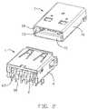
- FIG. 1is a top and front perspective view of an electrical connector of a first embodiment
- FIG. 2is a perspective view of the electrical connector and a counter connector
- FIG. 3is an exploded perspective view of the electrical connector shown in FIG. 1 ;
- FIG. 4is a perspective view of the connector without the shell thereon shown in FIG. 1 ;
- FIG. 5is an exploded perspective view of an electrical connector of a second embodiment
- FIG. 6is a perspective view of the connector without the shell thereon shown in FIG. 5 .
- an electrical connector 1 of a first embodiment of the present inventionis used to mate with a counter connector 7 .
- the counter connector 7comprises an insulating housing having a front mating tongue portion 71 and a shielding shell 70 surrounding the housing to define a mating cavity between the tongue portion 71 , the top wall and sidewalls 72 of the shell 70 .
- a plurality of terminals 73are arranged on the top surface of the tongue portion 71 .
- the connectorcomprises an insulating housing 2 , a plurality of spring terminal 3 , a shielding shell 4 and two spring detecting pins 6 .
- the insulating housing 2made from resin material, comprises a base portion 20 and a tongue portion 21 extending forward from a front face of the base portion.
- the tongue portion 21defines a top surface 210 and a bottom surface 211 forming two opposite large main surfaces and two opposite end surfaces 212 forming two opposite tiny side surface perpendicular to said two opposite main surfaces.
- the four terminals 3are retained in corresponding passageways 2110 on the bottom surface 211 of the tongue portion and each comprises a retaining portion 31 retained in the base portion, a solder portion 32 extending downwards from the retaining portion and toward a bottom face 201 of the base portion 20 and a contacting portion 30 extending forward from the retaining portion.
- the shielding shell 4surrounds and is retained on the base portion 20 and spacedly surrounds the tongue portion 21 to define a receiving cavity 43 .
- the shellcomprises a top wall 41 , a bottom wall and two sidewalls 42 perpendicularly connecting with the top and bottom wall to commonly define said receiving cavity 43 .
- the tongue portion 21 of the housingdefines a recess portion 2120 at each end surface 212 into which the two detecting pins 6 are inserted.
- the recess portion 2120 adjacent to the rear portion of the tongue portion 21opens outward and runs through the base portion rearwards.
- the detecting pin 6made from a metal slit tape and received in the recess portion 2120 , comprises a retaining section 61 , a leg portion 63 extending downwards from the retaining section and a contacting arm 60 from the retaining section.
- the retaining sectionhas at least one tab 611 at an upper and lower edge thereof and retained in the base portion of the housing.
- the contacting arm 60defines an outwards-projecting arc shaped contacting section 62 at a front end thereof and the contacting section 62 projects outwards beyond the end surface 212 of tongue portion and toward the sidewalls of the shell.
- the detecting pins 60respectively touch the inside of sidewalls 72 of the shell 70 of the counter connector 7 to complete an electrical connection and the inside of the shell 4 touch the outside of sidewalls 72 of the shell 70 .
- An insulating housing 8 of the electrical connectorcomprises a base portion 80 and a tongue portion 81 extending forward from the front surface thereof adjacent to the top thereof.
- a flange 82parallel extends forward from each end wall of the base portion 80 and beyond the front surface of the base portion.
- Each flangedefines a recess portion 821 in the inside thereof, which opens inwards and rearward runs through the base portion.
- the pair of detecting pins 6are received in the recess portions 821 of the flange and the arc portions 62 of the detecting pins project towards the tongue portion.
- the detecting pins 60respectively touch the outside of end walls 70 of the shell of the counter connector 7 to complete an electrical connection and the inside of the shell 4 touch the outside of the shell 70 of the shell 7 .
Landscapes
- Details Of Connecting Devices For Male And Female Coupling (AREA)
Abstract
Description
1. Field of the Invention
The present invention relates to an electrical connector having a pair of detecting pins.
2. Description of Related Art
U.S. Pat. No. 5,674,085 discloses an electrical connector having an insulating housing defining a tongue portion, a shielding shell surrounding the housing and conductive terminals in the tongue portion and a detecting pin. The detecting pin is retained in the housing and has a cantilever portion bent and extending below the tongue portion. The cantilever portion will engage with one conductive terminal when a mating connector is inserted into the connector.
However, electrical reliability of the terminals will face challenge since the terminal functions as a detecting pin synchronously. The cantilever is longer so that it might be permanently distorted.
Therefore, an electrical connector with improved detecting pins is desired to overcome the disadvantages of the related arts.
An object of the present invention is to provide an electrical connector with a pair of improved detecting pins.
In order to achieve above-mentioned object, an electrical connector includes an insulating housing defining a base portion and a tongue portion extending forwards from a front face of the base portion and a plurality of terminals. The tongue portion defines a recess portion at each of opposite end walls thereof. Each defines a solder portion extending towards a bottom face of the base portion and a contacting portion located on the tongue portion. A pair of detecting pins are located in recess portions and each comprises a leg portion extending out the base portion and an arc section projecting out beyond the end wall of the tongue portion to be touched by a sidewall of a shielding shell of the counter connector when the electrical connector is inserted by the counter connector.
Other objects, advantages and novel features of the present invention will become more apparent from the following detailed description of the present embodiment when taken in conjunction with the accompanying drawings.
Reference will now be made to the drawing figures to describe a preferred embodiment of the present invention in detail.
Referring toFIGS. 1 and 2 , anelectrical connector 1 of a first embodiment of the present invention is used to mate with acounter connector 7. Thecounter connector 7 comprises an insulating housing having a frontmating tongue portion 71 and ashielding shell 70 surrounding the housing to define a mating cavity between thetongue portion 71, the top wall andsidewalls 72 of theshell 70. A plurality ofterminals 73 are arranged on the top surface of thetongue portion 71.
Referring toFIGS. 3 and 4 , the connector comprises aninsulating housing 2, a plurality ofspring terminal 3, ashielding shell 4 and twospring detecting pins 6. Theinsulating housing 2 made from resin material, comprises abase portion 20 and atongue portion 21 extending forward from a front face of the base portion. Thetongue portion 21 defines atop surface 210 and abottom surface 211 forming two opposite large main surfaces and twoopposite end surfaces 212 forming two opposite tiny side surface perpendicular to said two opposite main surfaces. The fourterminals 3 are retained incorresponding passageways 2110 on thebottom surface 211 of the tongue portion and each comprises aretaining portion 31 retained in the base portion, asolder portion 32 extending downwards from the retaining portion and toward abottom face 201 of thebase portion 20 and a contactingportion 30 extending forward from the retaining portion. Theshielding shell 4 surrounds and is retained on thebase portion 20 and spacedly surrounds thetongue portion 21 to define areceiving cavity 43. The shell comprises atop wall 41, a bottom wall and twosidewalls 42 perpendicularly connecting with the top and bottom wall to commonly define said receivingcavity 43.
Referring toFIGS. 3 and 4 , thetongue portion 21 of the housing defines arecess portion 2120 at eachend surface 212 into which the two detectingpins 6 are inserted. Therecess portion 2120 adjacent to the rear portion of thetongue portion 21, opens outward and runs through the base portion rearwards. The detectingpin 6, made from a metal slit tape and received in therecess portion 2120, comprises aretaining section 61, aleg portion 63 extending downwards from the retaining section and a contactingarm 60 from the retaining section. The retaining section has at least onetab 611 at an upper and lower edge thereof and retained in the base portion of the housing. The contactingarm 60 defines an outwards-projecting arc shapedcontacting section 62 at a front end thereof and the contactingsection 62 projects outwards beyond theend surface 212 of tongue portion and toward the sidewalls of the shell.
As shown inFIG. 2 , the detectingpins 60 respectively touch the inside ofsidewalls 72 of theshell 70 of thecounter connector 7 to complete an electrical connection and the inside of theshell 4 touch the outside ofsidewalls 72 of theshell 70.
Another embodiment of an electrical connector is provided inFIGS. 5 and 6 . Aninsulating housing 8 of the electrical connector comprises abase portion 80 and atongue portion 81 extending forward from the front surface thereof adjacent to the top thereof. Aflange 82 parallel extends forward from each end wall of thebase portion 80 and beyond the front surface of the base portion. Each flange defines arecess portion 821 in the inside thereof, which opens inwards and rearward runs through the base portion. The pair of detectingpins 6 are received in therecess portions 821 of the flange and thearc portions 62 of the detecting pins project towards the tongue portion. The detectingpins 60 respectively touch the outside ofend walls 70 of the shell of thecounter connector 7 to complete an electrical connection and the inside of theshell 4 touch the outside of theshell 70 of theshell 7.
However, the disclosure is illustrative only, changes may be made in detail, especially in matter of shape, size, and arrangement of parts within the principles of the invention.
Claims (9)
1. An electrical connector comprising:
an insulating housing defining a base portion and a tongue portion extending forwards from a front face of the base portion, the tongue portion defining a recess portion at each of opposite end walls thereof;
a plurality of terminals, each defining a solder portion extending towards a bottom face of the base portion and a contacting portion located on the tongue portion; and
a pair of detecting pins being located in recess portions, each comprising a leg portion extending out the base portion and an arc section projecting out beyond the end wall of the tongue portion to be touched by a sidewall of a shielding shell of a counter connector when the electrical connector is inserted by the counter connector.
2. The electrical connector as described inclaim 1 , wherein each detecting pin comprises a retaining portion with at least one tab on an upper and lower edge thereof and a contacting arm straightly extending forward from the retaining portion with the arc section at a front end thereof.
3. The electrical connector as described inclaim 2 , wherein a leg portion extends downward from the retaining portion.
4. The electrical connector as described inclaim 3 , wherein the terminals are located in a bottom surface of the tongue portion.
5. The electrical connector as described inclaim 4 , further comprising a shielding shell retained on the base portion and surrounding the tongue portion to define a receiving cavity, the arc section projects towards the sidewalls of the shielding shell.
6. An electrical connector comprising:
an insulating housing defining a base portion, a tongue portion extending forwards from a front face of the base portion and a pair of flanges located spaced from and parallel to two opposite end walls of the tongue portion, the flanges defining a recess portion at each of opposite inside surfaces thereof;
a plurality of terminals, each defining a solder portion extending towards a bottom face of the base portion and a contacting portion located on the tongue portion; and
a pair of detecting pins being located in said recess portions, each comprising a leg portion extending out the base portion and an arc section projecting out beyond the inside surfaces of the flanges to be touched by a sidewall of a shielding shell of a counter connector when the electrical connector is inserted by the counter connector.
7. The electrical connector as described inclaim 6 , wherein each detecting pin comprises a retaining portion with at least one tab on an upper and lower edge thereof and a contacting arm straightly extending forward from the retaining portion with the arc section at a front end thereof.
8. An electrical connector comprising:
a frame like metallic shell defining a pair of opposite main walls and a pair of opposite side walls commonly defining a cavity;
an insulative housing received in the cavity and defining a base with a mating tongue extending forwardly therefrom, said mating tongue defining two opposite large main surfaces and two opposite tiny side surfaces perpendicular to said two opposite main surfaces, said main surfaces and said side surfaces commonly extending in a front-to-back direction from peripheral edges of a front face of the mating tongue, respectively;
a plurality of spring contacts disposed in the housing with contacting sections exposed upon one of said large main surface for imposing an asymmetric force upon a complementary connector, which is inserted into the cavity, in a vertical direction perpendicular to the front-to-back direction and main surface while parallel to the side surface; and
a pair of spring detecting terminals located around said two opposite tiny side surfaces, respectively, so as to impose essentially balanced and symmetric forces upon a metallic shield of said complementary connector along a transverse direction parallel to said large main surface while perpendicular to said side surface and said front-to-back direction and said vertical direction.
9. The electrical connector as claimed inclaim 8 , wherein said pair of spring detecting terminals is located on a pair of flanges of the housing, which are opposite to and spaced from the two corresponding side surfaces, respectively, to impose the corresponding forces upon the shield of the complementary connector in opposite direction toward each other.
Applications Claiming Priority (3)
| Application Number | Priority Date | Filing Date | Title |
|---|---|---|---|
| CN200720043638.9 | 2007-10-12 | ||
| CNU2007200436389UCN201130767Y (en) | 2007-10-12 | 2007-10-12 | electrical connector |
| CH200720043638U | 2007-10-12 |
Publications (2)
| Publication Number | Publication Date |
|---|---|
| US20090098772A1 US20090098772A1 (en) | 2009-04-16 |
| US7727026B2true US7727026B2 (en) | 2010-06-01 |
Family
ID=40018634
Family Applications (1)
| Application Number | Title | Priority Date | Filing Date |
|---|---|---|---|
| US12/286,358Expired - Fee RelatedUS7727026B2 (en) | 2007-10-12 | 2008-09-29 | Electrical connector with a pair of improved detecting pins |
Country Status (2)
| Country | Link |
|---|---|
| US (1) | US7727026B2 (en) |
| CN (1) | CN201130767Y (en) |
Cited By (31)
| Publication number | Priority date | Publication date | Assignee | Title |
|---|---|---|---|---|
| US20110092100A1 (en)* | 2009-10-16 | 2011-04-21 | Adc Telecommunications, Inc. | Managed connectivity in electrical systems and methods thereof |
| US7972181B1 (en)* | 2010-11-29 | 2011-07-05 | Shenzhen Oversea Win Technology Co., Ltd. | Compound female connector |
| USD648679S1 (en)* | 2010-03-18 | 2011-11-15 | Hon Hai Precision Ind. Co., Ltd. | Electrical connector |
| USD648680S1 (en)* | 2010-03-18 | 2011-11-15 | Hon Hai Precision Ind. Co., Ltd. | Electrical connector |
| US20120045943A1 (en)* | 2009-04-29 | 2012-02-23 | Md Elektronik Gmbh | Adapter element for serial data transfer in a vehicle |
| US20120231673A1 (en)* | 2011-03-09 | 2012-09-13 | Koji Hayashi | Receptacle connector and plug connector to be fitted to the receptacle connector |
| US20130149915A1 (en)* | 2011-11-28 | 2013-06-13 | Tyco Electronics Amp Korea Ltd. | Connection Plug For Portable Terminal |
| US20130244494A1 (en)* | 2012-03-14 | 2013-09-19 | Apple Inc. | Connector receptacle having split contacts |
| US20130316592A1 (en)* | 2012-05-25 | 2013-11-28 | Hon Hai Precision Industry Co., Ltd. | Electrical card connector |
| US20140051274A1 (en)* | 2012-08-14 | 2014-02-20 | Hon Hai Precision Industry Co., Ltd. | Electrical connector |
| US20140051303A1 (en)* | 2012-08-14 | 2014-02-20 | Hon Hai Precision Industry Co., Ltd. | Electrical connector |
| US20140051302A1 (en)* | 2012-08-14 | 2014-02-20 | Hon Hai Precision Industry Co., Ltd. | Electrical connector with detect contact |
| US8696369B2 (en) | 2010-09-09 | 2014-04-15 | Adc Telecommunications, Inc. | Electrical plug with main contacts and retractable secondary contacts |
| US8715012B2 (en) | 2011-04-15 | 2014-05-06 | Adc Telecommunications, Inc. | Managed electrical connectivity systems |
| US8992261B2 (en) | 2010-10-22 | 2015-03-31 | Adc Telecommunications, Inc. | Single-piece plug nose with multiple contact sets |
| US9011176B2 (en) | 2012-06-09 | 2015-04-21 | Apple Inc. | ESD path for connector receptacle |
| US9054440B2 (en) | 2009-10-19 | 2015-06-09 | Adc Telecommunications, Inc. | Managed electrical connectivity systems |
| US20150162714A1 (en)* | 2013-12-11 | 2015-06-11 | Foxconn Interconnect Technology Limited | Electrical connector with improved contacts |
| US9064022B2 (en) | 2011-05-17 | 2015-06-23 | Adc Telecommunications, Inc. | Component identification and tracking system for telecommunication networks |
| US9093796B2 (en) | 2012-07-06 | 2015-07-28 | Adc Telecommunications, Inc. | Managed electrical connectivity systems |
| US9140859B2 (en) | 2010-02-12 | 2015-09-22 | Tyco Electronics Services Gmbh | Managed fiber connectivity systems |
| US20150318645A1 (en)* | 2014-04-30 | 2015-11-05 | T-Conn Precision Corporation | Modular Inserted Connector Detecting Structure |
| US9203198B2 (en) | 2012-09-28 | 2015-12-01 | Commscope Technologies Llc | Low profile faceplate having managed connectivity |
| US9285552B2 (en) | 2013-02-05 | 2016-03-15 | Commscope Technologies Llc | Optical assemblies with managed connectivity |
| US9379501B2 (en) | 2013-02-05 | 2016-06-28 | Commscope Technologies Llc | Optical assemblies with managed connectivity |
| US9423570B2 (en) | 2013-02-05 | 2016-08-23 | Commscope Technologies Llc | Optical assemblies with managed connectivity |
| US9470742B2 (en) | 2012-08-03 | 2016-10-18 | Commscope Technologies Llc | Managed fiber connectivity systems |
| US9500814B2 (en) | 2014-03-26 | 2016-11-22 | Commscope Technologies Llc | Optical adapter module with managed connectivity |
| US20170040750A1 (en)* | 2013-07-19 | 2017-02-09 | Foxconn Interconnect Technology Limted | Flippable electrical connector |
| US10678001B2 (en) | 2009-10-16 | 2020-06-09 | Commscope Technologies Llc | Managed connectivity in fiber optic systems and methods thereof |
| US11158983B2 (en)* | 2017-11-02 | 2021-10-26 | Limoss (Shenzhen) Co., Ltd. | USB socket, button controller and smart appliance |
Families Citing this family (9)
| Publication number | Priority date | Publication date | Assignee | Title |
|---|---|---|---|---|
| CN103178405B (en)* | 2011-12-21 | 2015-09-02 | 神讯电脑(昆山)有限公司 | Can the jockey of detecting connection status, electrical connection module and electronic installation |
| JP2014157667A (en)* | 2013-02-14 | 2014-08-28 | Tyco Electronics Japan Kk | Electric connector |
| US8974240B2 (en)* | 2013-04-18 | 2015-03-10 | Hon Hai Precision Industry Co., Ltd. | Electrical connector with detect pins |
| JP6084136B2 (en)* | 2013-08-27 | 2017-02-22 | 日本航空電子工業株式会社 | USB receptacle |
| TWM475741U (en)* | 2013-09-10 | 2014-04-01 | Hon Hai Prec Ind Co Ltd | Electrical connector |
| JP6215119B2 (en)* | 2014-04-11 | 2017-10-18 | 日本航空電子工業株式会社 | USB receptacle |
| JP6308197B2 (en)* | 2015-11-10 | 2018-04-11 | 第一精工株式会社 | Electrical connector |
| DE102018000204A1 (en)* | 2018-01-12 | 2019-07-18 | Kostal Kontakt Systeme Gmbh | The connector assembly |
| CN116892707A (en)* | 2023-08-18 | 2023-10-17 | 武汉通用联合科技有限公司 | A snap-on LED lighting module |
Citations (15)
| Publication number | Priority date | Publication date | Assignee | Title |
|---|---|---|---|---|
| TW288046B (en) | 1993-05-08 | 1996-10-11 | Nat Science Council | Nucleotide sequence of cDNA of a thrombin-like enzyme (ancrod) from Calloselasma rhodostoma and amino acid sequence of ancrod therefrom |
| US5674085A (en) | 1996-05-24 | 1997-10-07 | The Whitaker Corporation | Electrical connector with switch |
| US5800192A (en) | 1996-08-30 | 1998-09-01 | Berg Technology, Inc. | Receptacle with integral sensor device |
| US6296521B1 (en)* | 2001-01-26 | 2001-10-02 | Hon Hai Precision Ind. Co., Ltd. | Electrical connector with power contacts positioned at lateral ends without increasing dimension thereof |
| TW497768U (en) | 2001-03-28 | 2002-08-01 | Suyin Corp | Improved structure of bus electric connector |
| US20050176306A1 (en)* | 2004-02-11 | 2005-08-11 | Ziqiang Zhu | Electrical connector |
| US6945824B1 (en)* | 2004-08-24 | 2005-09-20 | Cheng Uei Precision Industry Co., Ltd. | Connector assembly |
| TWM288046U (en) | 2005-10-03 | 2006-02-21 | Hon Hai Prec Ind Co Ltd | Electrical connector |
| US7207819B2 (en)* | 2005-09-09 | 2007-04-24 | Hon Hai Precision Ind. Co., Ltd. | Electrical connector with a detective switch |
| US7210945B1 (en)* | 2005-11-16 | 2007-05-01 | Wan-Fa Ying | HDMI connector assembly |
| US7255607B1 (en)* | 2006-12-05 | 2007-08-14 | Hon Hai Precision Ind. Co., Ltd. | Compatible electrical connector |
| TWM318233U (en) | 2007-01-26 | 2007-09-01 | Cheng Uei Prec Ind Co Ltd | HDMI connector |
| US7413467B1 (en)* | 2007-05-31 | 2008-08-19 | Cheng Uei Precision Industry Co., Ltd. | HDMI connector assembly |
| US20090061671A1 (en)* | 2007-09-03 | 2009-03-05 | Hon Hai Precision Ind. Co., Ltd | Electrical connector with a pair of improved detacting pins |
| US20090075517A1 (en)* | 2007-09-18 | 2009-03-19 | Hon Hai Precision Inc. Co., Ltd. | Electrical connector with an improved detecting pin |
- 2007
- 2007-10-12CNCNU2007200436389Upatent/CN201130767Y/ennot_activeExpired - Lifetime
- 2008
- 2008-09-29USUS12/286,358patent/US7727026B2/ennot_activeExpired - Fee Related
Patent Citations (15)
| Publication number | Priority date | Publication date | Assignee | Title |
|---|---|---|---|---|
| TW288046B (en) | 1993-05-08 | 1996-10-11 | Nat Science Council | Nucleotide sequence of cDNA of a thrombin-like enzyme (ancrod) from Calloselasma rhodostoma and amino acid sequence of ancrod therefrom |
| US5674085A (en) | 1996-05-24 | 1997-10-07 | The Whitaker Corporation | Electrical connector with switch |
| US5800192A (en) | 1996-08-30 | 1998-09-01 | Berg Technology, Inc. | Receptacle with integral sensor device |
| US6296521B1 (en)* | 2001-01-26 | 2001-10-02 | Hon Hai Precision Ind. Co., Ltd. | Electrical connector with power contacts positioned at lateral ends without increasing dimension thereof |
| TW497768U (en) | 2001-03-28 | 2002-08-01 | Suyin Corp | Improved structure of bus electric connector |
| US20050176306A1 (en)* | 2004-02-11 | 2005-08-11 | Ziqiang Zhu | Electrical connector |
| US6945824B1 (en)* | 2004-08-24 | 2005-09-20 | Cheng Uei Precision Industry Co., Ltd. | Connector assembly |
| US7207819B2 (en)* | 2005-09-09 | 2007-04-24 | Hon Hai Precision Ind. Co., Ltd. | Electrical connector with a detective switch |
| TWM288046U (en) | 2005-10-03 | 2006-02-21 | Hon Hai Prec Ind Co Ltd | Electrical connector |
| US7210945B1 (en)* | 2005-11-16 | 2007-05-01 | Wan-Fa Ying | HDMI connector assembly |
| US7255607B1 (en)* | 2006-12-05 | 2007-08-14 | Hon Hai Precision Ind. Co., Ltd. | Compatible electrical connector |
| TWM318233U (en) | 2007-01-26 | 2007-09-01 | Cheng Uei Prec Ind Co Ltd | HDMI connector |
| US7413467B1 (en)* | 2007-05-31 | 2008-08-19 | Cheng Uei Precision Industry Co., Ltd. | HDMI connector assembly |
| US20090061671A1 (en)* | 2007-09-03 | 2009-03-05 | Hon Hai Precision Ind. Co., Ltd | Electrical connector with a pair of improved detacting pins |
| US20090075517A1 (en)* | 2007-09-18 | 2009-03-19 | Hon Hai Precision Inc. Co., Ltd. | Electrical connector with an improved detecting pin |
Cited By (81)
| Publication number | Priority date | Publication date | Assignee | Title |
|---|---|---|---|---|
| US20120045943A1 (en)* | 2009-04-29 | 2012-02-23 | Md Elektronik Gmbh | Adapter element for serial data transfer in a vehicle |
| US8628354B2 (en)* | 2009-04-29 | 2014-01-14 | Md Elektronik Gmbh | Adapter element for serial data transfer in a vehicle |
| US11191173B2 (en) | 2009-10-16 | 2021-11-30 | Commscope Technologies Llc | Managed connectivity in electrical systems and methods thereof |
| US9401552B2 (en) | 2009-10-16 | 2016-07-26 | Commscope Technologies Llc | Managed connectivity in electrical systems and methods thereof |
| US11630269B2 (en) | 2009-10-16 | 2023-04-18 | Commscope Technologies Llc | Managed connectivity in fiber optic systems and methods thereof |
| US12235494B2 (en) | 2009-10-16 | 2025-02-25 | Commscope Technologies Llc | Managed connectivity in fiber optic systems and methods thereof |
| US10678001B2 (en) | 2009-10-16 | 2020-06-09 | Commscope Technologies Llc | Managed connectivity in fiber optic systems and methods thereof |
| US9769939B2 (en) | 2009-10-16 | 2017-09-19 | Commscope Technologies Llc | Managed connectivity in electrical systems and methods thereof |
| US8992260B2 (en) | 2009-10-16 | 2015-03-31 | Adc Telecommunications, Inc. | Managed connectivity in electrical systems and methods thereof |
| US9967983B2 (en) | 2009-10-16 | 2018-05-08 | Commscope Technologies Llc | Managed connectivity in electrical systems and methods thereof |
| US11231555B2 (en) | 2009-10-16 | 2022-01-25 | Commscope Technologies Llc | Managed connectivity in fiber optic systems and methods thereof |
| US10470320B2 (en) | 2009-10-16 | 2019-11-05 | Commscope Technologies Llc | Managed connectivity in electrical systems and methods thereof |
| US20110092100A1 (en)* | 2009-10-16 | 2011-04-21 | Adc Telecommunications, Inc. | Managed connectivity in electrical systems and methods thereof |
| US10574008B2 (en) | 2009-10-19 | 2020-02-25 | Commscope Technologies Llc | Managed electrical connectivity systems |
| US10177514B2 (en) | 2009-10-19 | 2019-01-08 | Commscope Technologies Llc | Managed electrical connectivity systems |
| US9595797B2 (en) | 2009-10-19 | 2017-03-14 | Commscope Technologies Llc | Managed electrical connectivity systems |
| US11469560B2 (en) | 2009-10-19 | 2022-10-11 | Commscope Technologies Llc | Managed electrical connectivity systems |
| US11862912B2 (en) | 2009-10-19 | 2024-01-02 | Commscope Technologies Llc | Managed electrical connectivity systems |
| US10958024B2 (en) | 2009-10-19 | 2021-03-23 | Commscope Technologies Llc | Managed electrical connectivity systems |
| US9054440B2 (en) | 2009-10-19 | 2015-06-09 | Adc Telecommunications, Inc. | Managed electrical connectivity systems |
| US9140859B2 (en) | 2010-02-12 | 2015-09-22 | Tyco Electronics Services Gmbh | Managed fiber connectivity systems |
| US9632255B2 (en) | 2010-02-12 | 2017-04-25 | Commscope Technologies Llc | Managed fiber connectivity systems |
| US11378755B2 (en) | 2010-02-12 | 2022-07-05 | Commscope Technologies Llc | Managed fiber connectivity systems |
| US12306444B2 (en) | 2010-02-12 | 2025-05-20 | Commscope Technologies Llc | Managed fiber connectivity systems |
| US10983285B2 (en) | 2010-02-12 | 2021-04-20 | Commscope Technologies Llc | Managed fiber connectivity systems |
| US9684134B2 (en) | 2010-02-12 | 2017-06-20 | Commscope Technologies Llc | Managed fiber connectivity systems |
| US10088636B2 (en) | 2010-02-12 | 2018-10-02 | Commscope Technologies Llc | Managed fiber connectivity systems |
| US9417399B2 (en) | 2010-02-12 | 2016-08-16 | Commscope Technologies Llc | Managed fiber connectivity systems |
| US9804337B2 (en) | 2010-02-12 | 2017-10-31 | Commscope Technologies Llc | Managed fiber connectivity systems |
| US10473864B2 (en) | 2010-02-12 | 2019-11-12 | Commscope Technologies Llc | Managed fiber connectivity systems |
| US11899246B2 (en) | 2010-02-12 | 2024-02-13 | Commscope Technologies Llc | Managed fiber connectivity systems |
| USD648680S1 (en)* | 2010-03-18 | 2011-11-15 | Hon Hai Precision Ind. Co., Ltd. | Electrical connector |
| USD648679S1 (en)* | 2010-03-18 | 2011-11-15 | Hon Hai Precision Ind. Co., Ltd. | Electrical connector |
| US8696369B2 (en) | 2010-09-09 | 2014-04-15 | Adc Telecommunications, Inc. | Electrical plug with main contacts and retractable secondary contacts |
| US8992261B2 (en) | 2010-10-22 | 2015-03-31 | Adc Telecommunications, Inc. | Single-piece plug nose with multiple contact sets |
| US7972181B1 (en)* | 2010-11-29 | 2011-07-05 | Shenzhen Oversea Win Technology Co., Ltd. | Compound female connector |
| US20120231673A1 (en)* | 2011-03-09 | 2012-09-13 | Koji Hayashi | Receptacle connector and plug connector to be fitted to the receptacle connector |
| CN102683943A (en)* | 2011-03-09 | 2012-09-19 | 矢崎总业株式会社 | Receptacle connector and plug connector to be fitted to the receptacle connector |
| US8715012B2 (en) | 2011-04-15 | 2014-05-06 | Adc Telecommunications, Inc. | Managed electrical connectivity systems |
| US8944856B2 (en) | 2011-04-15 | 2015-02-03 | Adc Telecommunications, Inc. | Managed electrical connectivity systems |
| US9502843B2 (en) | 2011-04-15 | 2016-11-22 | Commscope Technologies Llc | Managed electrical connectivity systems |
| US9147983B2 (en) | 2011-04-15 | 2015-09-29 | Adc Telecommunications, Inc. | Managed electrical connectivity systems |
| US9064022B2 (en) | 2011-05-17 | 2015-06-23 | Adc Telecommunications, Inc. | Component identification and tracking system for telecommunication networks |
| US20130149915A1 (en)* | 2011-11-28 | 2013-06-13 | Tyco Electronics Amp Korea Ltd. | Connection Plug For Portable Terminal |
| US8961242B2 (en)* | 2011-11-28 | 2015-02-24 | Tyco Electronics Amp Korea Ltd. | Connection plug for portable terminal |
| US20130244494A1 (en)* | 2012-03-14 | 2013-09-19 | Apple Inc. | Connector receptacle having split contacts |
| US8920197B2 (en)* | 2012-03-14 | 2014-12-30 | Apple Inc. | Connector receptacle with ground contact having split rear extensions |
| US20130316592A1 (en)* | 2012-05-25 | 2013-11-28 | Hon Hai Precision Industry Co., Ltd. | Electrical card connector |
| US9011176B2 (en) | 2012-06-09 | 2015-04-21 | Apple Inc. | ESD path for connector receptacle |
| US9437990B2 (en) | 2012-07-06 | 2016-09-06 | Commscope Technologies Llc | Managed electrical connectivity systems |
| US9093796B2 (en) | 2012-07-06 | 2015-07-28 | Adc Telecommunications, Inc. | Managed electrical connectivity systems |
| US9470742B2 (en) | 2012-08-03 | 2016-10-18 | Commscope Technologies Llc | Managed fiber connectivity systems |
| US20140051302A1 (en)* | 2012-08-14 | 2014-02-20 | Hon Hai Precision Industry Co., Ltd. | Electrical connector with detect contact |
| US20140051274A1 (en)* | 2012-08-14 | 2014-02-20 | Hon Hai Precision Industry Co., Ltd. | Electrical connector |
| US20140051303A1 (en)* | 2012-08-14 | 2014-02-20 | Hon Hai Precision Industry Co., Ltd. | Electrical connector |
| US9525255B2 (en) | 2012-09-28 | 2016-12-20 | Commscope Technologies Llc | Low profile faceplate having managed connectivity |
| US9203198B2 (en) | 2012-09-28 | 2015-12-01 | Commscope Technologies Llc | Low profile faceplate having managed connectivity |
| US10571641B2 (en) | 2013-02-05 | 2020-02-25 | Commscope Technologies Llc | Optical assemblies with managed connectivity |
| US9423570B2 (en) | 2013-02-05 | 2016-08-23 | Commscope Technologies Llc | Optical assemblies with managed connectivity |
| US12235505B2 (en) | 2013-02-05 | 2025-02-25 | Commscope Technologies Llc | Fiber optic cassette arrangement |
| US9285552B2 (en) | 2013-02-05 | 2016-03-15 | Commscope Technologies Llc | Optical assemblies with managed connectivity |
| US10012813B2 (en) | 2013-02-05 | 2018-07-03 | Commscope Technologies Llc | Optical assemblies with managed connectivity |
| US11867952B2 (en) | 2013-02-05 | 2024-01-09 | Commscope Technologies Llc | Optical assemblies with managed connectivity |
| US10746943B2 (en) | 2013-02-05 | 2020-08-18 | Commscope Technologies Llc | Optical assemblies with managed connectivity |
| US9778424B2 (en) | 2013-02-05 | 2017-10-03 | Commscope Technologies Llc | Optical assemblies with managed connectivity |
| US9735523B2 (en) | 2013-02-05 | 2017-08-15 | Commscope Connectivity Uk Limited | Optical assemblies with managed connectivity |
| US11143833B2 (en) | 2013-02-05 | 2021-10-12 | Commscope Technologies Llc | Optical assemblies with managed connectivity |
| US9379501B2 (en) | 2013-02-05 | 2016-06-28 | Commscope Technologies Llc | Optical assemblies with managed connectivity |
| US11714246B2 (en) | 2013-02-05 | 2023-08-01 | Commscope Technologies Llc | Optical assemblies with contoured base |
| US10268000B2 (en) | 2013-02-05 | 2019-04-23 | Commscope Technologies Llc | Optical assemblies with managed connectivity |
| US11327248B2 (en) | 2013-02-05 | 2022-05-10 | Commscope Technologies Llc | Optical assemblies with managed connectivity |
| US20170040750A1 (en)* | 2013-07-19 | 2017-02-09 | Foxconn Interconnect Technology Limted | Flippable electrical connector |
| US10158197B2 (en)* | 2013-07-19 | 2018-12-18 | Foxconn Interconnect Technology Limited | Flippable electrical connector |
| US9673580B2 (en)* | 2013-12-11 | 2017-06-06 | Foxconn Interconnect Technology Limited | Electrical connector with improved contacts |
| US20150162714A1 (en)* | 2013-12-11 | 2015-06-11 | Foxconn Interconnect Technology Limited | Electrical connector with improved contacts |
| US9500814B2 (en) | 2014-03-26 | 2016-11-22 | Commscope Technologies Llc | Optical adapter module with managed connectivity |
| US9995883B2 (en) | 2014-03-26 | 2018-06-12 | Commscope Technologies Llc | Optical adapter module with managed connectivity |
| US10509177B2 (en) | 2014-03-26 | 2019-12-17 | Commscope Technologies Llc | Optical adapter module with managed connectivity |
| US9543714B2 (en)* | 2014-04-30 | 2017-01-10 | T-Conn Precision Corporation | Modular inserted connector detecting structure |
| US20150318645A1 (en)* | 2014-04-30 | 2015-11-05 | T-Conn Precision Corporation | Modular Inserted Connector Detecting Structure |
| US11158983B2 (en)* | 2017-11-02 | 2021-10-26 | Limoss (Shenzhen) Co., Ltd. | USB socket, button controller and smart appliance |
Also Published As
| Publication number | Publication date |
|---|---|
| CN201130767Y (en) | 2008-10-08 |
| US20090098772A1 (en) | 2009-04-16 |
Similar Documents
| Publication | Publication Date | Title |
|---|---|---|
| US7727026B2 (en) | Electrical connector with a pair of improved detecting pins | |
| US7588470B2 (en) | Electrical connector with an improved detecting pin | |
| US9450354B2 (en) | Dual orientation connector and assembly of the same | |
| US9762009B2 (en) | Plug connector insertable in two orientations and having a metallic shield plate with arms with hook structures | |
| US9979134B2 (en) | Electrical connector with improved shielding performance | |
| US9385482B2 (en) | Electrical connector with grounding plate | |
| US8905779B2 (en) | Electrical connector having a plurality of detecting pins | |
| US20090061671A1 (en) | Electrical connector with a pair of improved detacting pins | |
| US8133078B2 (en) | Electrical connector featured USB/eSATA interfaces | |
| US9356404B2 (en) | Electrical connector | |
| US20160064869A1 (en) | Electrical connector with improved grounding mechanism | |
| US20090247014A1 (en) | Electrical connector having a shell with a portion retained in an insulative housing | |
| US8070528B2 (en) | Electrical connector having improved terminals | |
| US9391410B2 (en) | Electrical connector with improved shell | |
| JP2010129540A (en) | Electrical connector | |
| US9531143B2 (en) | RJ45 socket connector having a conductive terminal for preventing yield due to mistaken insertion | |
| US20150044899A1 (en) | Electrical connector with additional exterior shell | |
| US7618268B2 (en) | Electrical connector with reliable mating frame mating with another connector | |
| CN109301570B (en) | Electric connector | |
| US9413111B2 (en) | Electrical connector assembly having foolproof structure | |
| US20110183548A1 (en) | Electrical connector with improved metal shell | |
| US20150295335A1 (en) | Electrical connector with improved contacts | |
| CN211320383U (en) | Terminal Assemblies and Board-to-Board Connector Assemblies | |
| US20120184147A1 (en) | Electrical connector having small size | |
| TWM497355U (en) | Electrical receptacle connector |
Legal Events
| Date | Code | Title | Description |
|---|---|---|---|
| AS | Assignment | Owner name:HON HAI PRECISION IND. CO., LTD., TAIWAN Free format text:ASSIGNMENT OF ASSIGNORS INTEREST;ASSIGNORS:QIN, FA-XING;WANG, ZHEN-SHENG;REEL/FRAME:021682/0249 Effective date:20080924 Owner name:HON HAI PRECISION IND. CO., LTD.,TAIWAN Free format text:ASSIGNMENT OF ASSIGNORS INTEREST;ASSIGNORS:QIN, FA-XING;WANG, ZHEN-SHENG;REEL/FRAME:021682/0249 Effective date:20080924 | |
| FPAY | Fee payment | Year of fee payment:4 | |
| FEPP | Fee payment procedure | Free format text:MAINTENANCE FEE REMINDER MAILED (ORIGINAL EVENT CODE: REM.) | |
| LAPS | Lapse for failure to pay maintenance fees | Free format text:PATENT EXPIRED FOR FAILURE TO PAY MAINTENANCE FEES (ORIGINAL EVENT CODE: EXP.) | |
| STCH | Information on status: patent discontinuation | Free format text:PATENT EXPIRED DUE TO NONPAYMENT OF MAINTENANCE FEES UNDER 37 CFR 1.362 | |
| FP | Lapsed due to failure to pay maintenance fee | Effective date:20180601 |