US7726825B2 - Lighted power outlet system and method - Google Patents
Lighted power outlet system and methodDownload PDFInfo
- Publication number
- US7726825B2 US7726825B2US12/035,801US3580108AUS7726825B2US 7726825 B2US7726825 B2US 7726825B2US 3580108 AUS3580108 AUS 3580108AUS 7726825 B2US7726825 B2US 7726825B2
- Authority
- US
- United States
- Prior art keywords
- light
- neutral
- positive
- outlets
- aperture
- Prior art date
- Legal status (The legal status is an assumption and is not a legal conclusion. Google has not performed a legal analysis and makes no representation as to the accuracy of the status listed.)
- Expired - Fee Related
Links
- 238000000034methodMethods0.000titleclaimsdescription14
- 230000007935neutral effectEffects0.000claimsdescription40
- 230000005540biological transmissionEffects0.000claimsdescription2
- 230000008878couplingEffects0.000claims2
- 238000010168coupling processMethods0.000claims2
- 238000005859coupling reactionMethods0.000claims2
- 230000001105regulatory effectEffects0.000description4
- 238000010586diagramMethods0.000description2
- 230000003750conditioning effectEffects0.000description1
- 238000005286illuminationMethods0.000description1
- 238000003780insertionMethods0.000description1
- 230000037431insertionEffects0.000description1
- 238000012986modificationMethods0.000description1
- 230000004048modificationEffects0.000description1
- 230000004304visual acuityEffects0.000description1
Images


Classifications
- H—ELECTRICITY
- H01—ELECTRIC ELEMENTS
- H01R—ELECTRICALLY-CONDUCTIVE CONNECTIONS; STRUCTURAL ASSOCIATIONS OF A PLURALITY OF MUTUALLY-INSULATED ELECTRICAL CONNECTING ELEMENTS; COUPLING DEVICES; CURRENT COLLECTORS
- H01R25/00—Coupling parts adapted for simultaneous co-operation with two or more identical counterparts, e.g. for distributing energy to two or more circuits
- H01R25/003—Coupling parts adapted for simultaneous co-operation with two or more identical counterparts, e.g. for distributing energy to two or more circuits the coupling part being secured only to wires or cables
- H—ELECTRICITY
- H01—ELECTRIC ELEMENTS
- H01R—ELECTRICALLY-CONDUCTIVE CONNECTIONS; STRUCTURAL ASSOCIATIONS OF A PLURALITY OF MUTUALLY-INSULATED ELECTRICAL CONNECTING ELEMENTS; COUPLING DEVICES; CURRENT COLLECTORS
- H01R13/00—Details of coupling devices of the kinds covered by groups H01R12/70 or H01R24/00 - H01R33/00
- H01R13/66—Structural association with built-in electrical component
- H01R13/717—Structural association with built-in electrical component with built-in light source
- H01R13/7175—Light emitting diodes (LEDs)
Definitions
- the present inventionis directed generally to electrical power outlets.
- Electrical power outletssuch as found in electrical power strips, are fashioned to receive plugs that terminate electrical cords or other electrical transmission media to furnish electrical power to equipment or other devices. Engagement of the plugs with the power outlets requires spatial alignment of plug prongs with terminal apertures of the outlets and then subsequent insertion of the plug prongs therein. Such engagement procedures can be problematic in dimly lit areas and/or areas that have other challenging visual acuity issues.
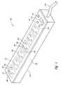
- FIG. 1is a front perspective view of a lighted power outlet system according to the present invention.
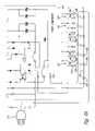
- FIG. 2is a schematic diagram of the outlet system of FIG. 1 .
- FIG. 2Ais a schematic diagram of a particular version of the outlet system of FIG. 2 showing one implementation of the power components.
- FIG. 3is an enlarged partial front perspective view of the outlet system of FIG. 1 in a lit condition.
- FIG. 4is a back perspective view of the outlet system of FIG. 1 .
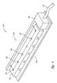
- FIG. 5is a front perspective view of the outlet system of FIG. 1 with exterior housing removed.
- FIG. 6is a front top view of the outlet system of FIG. 1 with exterior housing removed.
- FIG. 7is a back perspective view of the outlet system of FIG. 1 with exterior housing removed.
- a lighted power outlet system and methodis present herein to include light emitters, such as light emitting diodes or other light emitting devices.
- the light emittersare internally positioned within the interior of the outlet system so that light is projected through the terminal apertures of the outlets.
- the projected lightis visible from locations exterior to the outlet system to assist in guiding alignment of plug prongs with terminal apertures for engagement of electrical plugs with outlets of the outlet system.
- a light power outlet system 100is depicted in FIG. 1 as including a plurality of outlets 102 each having a neutral terminal aperture 104 , a positive terminal aperture 106 , and a ground terminal aperture 108 .
- the outlet system 100receives electrical power from a supply cable 110 to be distributed through the outlets 102 to devices (not shown) that are coupled thereto.
- the outlet system 100has a power switch 112 with on and off positions (shown in the off position in FIG. 1 ). When the power switch 112 is in the off position no electrical power is available to the outlets 102 so that devices coupled to the outlets are not furnished electrical power by the outlet system 100 . When the power switch 112 is in the on position (shown in FIG. 3 and discussed further below) electrical power is available to the outlets 102 so that devices coupled to the outlets are furnished electrical power by the outlet system 100 .
- the outlet system 100further includes a reset and/or fuse 114 , a surge protection indicator 116 , and a polarity and/or ground indicator 118 all of which can be optional accessories with other implementations.
- the outlet system 100further includes a housing 120 to provide protection and/or aesthetic functionality for internal components housed therein.
- the outlet systemis depicted as having a front side 122 and a backside 124 .
- Components, both external and internal, of the outlet system 100are represented schematically in FIG. 2 to include the supply cable 110 (shown with its plug), the plurality of outlets 102 , power components 126 , a plurality of light emitters 128 , a regulating diode 130 , and a regulating resistor 132 .
- the power components 126are provided for power conditioning and are otherwise involved with supplying electrical power to the outlets 102 as received through the supply cable 110 .
- a particular implementation for the power components 126is shown in FIG. 2A and other implementations can also be used.
- the light emitters 128are shown in a one to one association with outlets 102 such that a different one of the light emitters is paired with a different one of the outlets.
- other associationscan be used such as one of the light emitters being associated with more than one of the outlets (one to many association), or more than one of the light emitters being associated with one of the outlets (many to one association), or other combinations thereof.
- the light emitters 128are schematically depicted as being light emitting diodes, in other implementations, other devices that emit light can be used.
- the regulating diode 130 and regulating resistor 132are provided to adjust electrical conditions to match requirements of the light emitters 128 .
- the light emitters 128positioned inside the interior of the housing 120 are energized to emit light.
- a portion of the emitted lightis allowed to escape from the interior of the housing 120 through the neutral aperture 104 , the positive aperture 106 , and the ground aperture 108 of each of the outlets 102 to attract the attention of a sighted observer positioned in the vicinity of outlet system 100 .
- the aperturesare more clearly visible to an observer to assist the observer in guiding the prongs of a plug for engagement with one of the outlets 102 .
- a terminal carrier section 136is generally located on the backside of the outlet system 100 to among other things physically support and retain the light emitters 128 in predetermined positions advantageous to directing at least a portion of light emitted therefrom to the respective one of the outlets 102 for each of the light emitters.
- the terminal carrier section 136can be removably attached to a portion of the housing and to the remainder of the outlet system 100 to allow for ready access to the interior of the housing 120 for servicing of the power components 126 and/or the light emitters 128 .
- FIGS. 5-7include views of the interior of the outlet system 100 with the housing 120 having been removed.
- Each of the outlets 102includes a neutral terminal 104 a (aligned and associated with the neutral aperture 104 to receive the neutral prong of a plug), a positive terminal 106 a (aligned and associated with the positive aperture 104 to receive the positive prong of a plug), and a ground terminal 108 a (aligned and associated with the ground aperture 104 to receive the ground prong of a plug) with a different one of the light emitters 128 positioned therebetween (as better shown in FIG. 6 ).
- a single one of the light emitters 128is able to project emitted light through the neutral aperture 104 , the positive aperture 106 and the ground aperture 108 of an associated one of the outlets 102 thereby reducing the number of light emitters that might otherwise be needed for a desired level of exterior illumination through the apertures of the outlet.
- other implementationsmay have other numbers of the light emitters 128 associated with numbers of the outlets 102 with consequential varying of positioning of the light emitters with respect to the neutral terminal 104 a , the positive terminal 106 a , and the ground terminal 108 a of one or more of the outlets.
Landscapes
- Physics & Mathematics (AREA)
- Engineering & Computer Science (AREA)
- Microelectronics & Electronic Packaging (AREA)
- Optics & Photonics (AREA)
- Details Of Connecting Devices For Male And Female Coupling (AREA)
Abstract
Description
Claims (31)
Priority Applications (4)
| Application Number | Priority Date | Filing Date | Title |
|---|---|---|---|
| US12/035,801US7726825B2 (en) | 2008-02-22 | 2008-02-22 | Lighted power outlet system and method |
| CA002655038ACA2655038A1 (en) | 2008-02-22 | 2009-02-20 | Lighted power outlet system and method |
| CN2009200073492UCN201450190U (en) | 2008-02-22 | 2009-02-20 | Light-emitting power outlet system |
| MX2011007975AMX2011007975A (en) | 2008-02-22 | 2011-07-28 | Lighted power outlet system and method. |
Applications Claiming Priority (1)
| Application Number | Priority Date | Filing Date | Title |
|---|---|---|---|
| US12/035,801US7726825B2 (en) | 2008-02-22 | 2008-02-22 | Lighted power outlet system and method |
Publications (2)
| Publication Number | Publication Date |
|---|---|
| US20090213567A1 US20090213567A1 (en) | 2009-08-27 |
| US7726825B2true US7726825B2 (en) | 2010-06-01 |
Family
ID=40983722
Family Applications (1)
| Application Number | Title | Priority Date | Filing Date |
|---|---|---|---|
| US12/035,801Expired - Fee RelatedUS7726825B2 (en) | 2008-02-22 | 2008-02-22 | Lighted power outlet system and method |
Country Status (4)
| Country | Link |
|---|---|
| US (1) | US7726825B2 (en) |
| CN (1) | CN201450190U (en) |
| CA (1) | CA2655038A1 (en) |
| MX (1) | MX2011007975A (en) |
Cited By (15)
| Publication number | Priority date | Publication date | Assignee | Title |
|---|---|---|---|---|
| US20100277892A1 (en)* | 2009-05-01 | 2010-11-04 | American Power Conversion Corporation | Power device with lighted outlets |
| US20110228552A1 (en)* | 2010-03-17 | 2011-09-22 | Leviton Manufacturing Company, Inc. | Faceplate guidelight system |
| USD674753S1 (en) | 2010-08-13 | 2013-01-22 | Leviton Manufacturing Co., Inc. | Wiring device with illumination |
| US8444309B2 (en) | 2010-08-13 | 2013-05-21 | Leviton Manufacturing Company, Inc. | Wiring device with illumination |
| US8686593B2 (en) | 2010-09-27 | 2014-04-01 | Schneider Electric It Corporation | Systems and methods of power device lighting |
| US9022605B2 (en) | 2011-09-08 | 2015-05-05 | Irving E. Bushnell | Charging connection device with illumination and associated methods |
| US9112321B2 (en)* | 2010-12-30 | 2015-08-18 | Leviton Manufacturing Company, Inc. | Illuminated receptacle |
| US9502832B1 (en) | 2015-12-07 | 2016-11-22 | Mustafa Majeed Ullahkhan | Duplex receptacle having a plurality of LEDs to illuminate the sockets |
| US20170104299A1 (en)* | 2015-10-09 | 2017-04-13 | Kimberly Vu | Illuminated Power Strip |
| US9941644B1 (en)* | 2017-06-23 | 2018-04-10 | Cyber Power Systems, Inc. | Power outlet device |
| US9970641B2 (en) | 2016-06-08 | 2018-05-15 | Kevin Mousavi | Electrical outlet with covering and light and method of use for the same |
| US20180183156A1 (en)* | 2016-12-23 | 2018-06-28 | Hon Hai Precision Industry Co., Ltd. | Connecting terminal and power distributing unit using the same |
| US20180183194A1 (en)* | 2016-12-23 | 2018-06-28 | Hon Hai Precision Industry Co., Ltd. | Power distributing socket and power distributing unit using the same |
| US10566746B1 (en)* | 2019-01-29 | 2020-02-18 | George Breeden | Illuminated electricity distribution device |
| US11131692B1 (en)* | 2019-04-23 | 2021-09-28 | Amazon Technologies, Inc. | Line isolating power connector |
Families Citing this family (4)
| Publication number | Priority date | Publication date | Assignee | Title |
|---|---|---|---|---|
| US8038454B2 (en)* | 2010-03-09 | 2011-10-18 | American Power Conversion Corporation | Back-mount ganged electrical outlets |
| US10524377B2 (en) | 2018-01-31 | 2019-12-31 | Eaton Intelligent Power Limited | Power distribution unit with interior busbars |
| MX2021001989A (en)* | 2018-08-22 | 2021-04-28 | Hubbell Inc | Illuminated power receptacle. |
| FR3088147B1 (en)* | 2018-11-06 | 2020-11-20 | Legrand France | POWER SOCKET WITH LIGHT SOURCE |
Citations (15)
| Publication number | Priority date | Publication date | Assignee | Title |
|---|---|---|---|---|
| US2189676A (en)* | 1938-06-08 | 1940-02-06 | Lester J Pfohl | Electric outlet connection |
| US2612597A (en)* | 1947-09-08 | 1952-09-30 | Elwin W Sherrard | Illuminated electric outlet fixture |
| US3265888A (en)* | 1963-12-05 | 1966-08-09 | Hubbell Inc Harvey | Lighted receptacle |
| US5883445A (en)* | 1996-10-22 | 1999-03-16 | Holman; Frank T. | Power sharing device |
| US6109760A (en) | 1998-12-14 | 2000-08-29 | Daimlerchrysler Corporation | Illuminated power outlet |
| US6827602B2 (en) | 2003-04-30 | 2004-12-07 | Leviton Manufacturing Co., Inc. | Hospital grade receptacle with power light indicator |
| US6857760B2 (en) | 2003-01-24 | 2005-02-22 | Chao Chuan Chien | Power outlet with night-vision-function |
| US20050124209A1 (en)* | 2002-02-14 | 2005-06-09 | Currie Robert M. | Illuminated electrical cords and outlets |
| US7004595B1 (en)* | 2004-03-12 | 2006-02-28 | James Marshall Stoddard | Illuminated electrical plug adapter |
| US7011422B2 (en) | 2002-10-16 | 2006-03-14 | Robertson Jonas J | Illuminated power strip and electrical outlet |
| US7036948B1 (en)* | 2003-08-11 | 2006-05-02 | Bryan Wyatt | Illuminated electrical outlet and light switch |
| US7086892B2 (en) | 2003-02-28 | 2006-08-08 | Leviton Manufacturing Co., Inc. | Live circuit indicator for plugs and receptacles |
| US7168974B2 (en) | 2004-04-08 | 2007-01-30 | Leviton Manufacturing Co., Inc. | Three phase lighted plugs and connectors for indicating the absence of at least one phase |
| US20070193866A1 (en) | 2006-01-18 | 2007-08-23 | John Eder | Lampholder |
| US20090141477A1 (en)* | 2007-12-04 | 2009-06-04 | Pass & Seymour, Inc. | Illuminated Face Receptacle Structure |
- 2008
- 2008-02-22USUS12/035,801patent/US7726825B2/ennot_activeExpired - Fee Related
- 2009
- 2009-02-20CNCN2009200073492Upatent/CN201450190U/ennot_activeExpired - Fee Related
- 2009-02-20CACA002655038Apatent/CA2655038A1/ennot_activeAbandoned
- 2011
- 2011-07-28MXMX2011007975Apatent/MX2011007975A/enactiveIP Right Grant
Patent Citations (16)
| Publication number | Priority date | Publication date | Assignee | Title |
|---|---|---|---|---|
| US2189676A (en)* | 1938-06-08 | 1940-02-06 | Lester J Pfohl | Electric outlet connection |
| US2612597A (en)* | 1947-09-08 | 1952-09-30 | Elwin W Sherrard | Illuminated electric outlet fixture |
| US3265888A (en)* | 1963-12-05 | 1966-08-09 | Hubbell Inc Harvey | Lighted receptacle |
| US5883445A (en)* | 1996-10-22 | 1999-03-16 | Holman; Frank T. | Power sharing device |
| US6109760A (en) | 1998-12-14 | 2000-08-29 | Daimlerchrysler Corporation | Illuminated power outlet |
| US7121707B2 (en)* | 2002-02-14 | 2006-10-17 | Plastic Inventions And Patents, Inc. | Illuminated electrical cords and outlets |
| US20050124209A1 (en)* | 2002-02-14 | 2005-06-09 | Currie Robert M. | Illuminated electrical cords and outlets |
| US7011422B2 (en) | 2002-10-16 | 2006-03-14 | Robertson Jonas J | Illuminated power strip and electrical outlet |
| US6857760B2 (en) | 2003-01-24 | 2005-02-22 | Chao Chuan Chien | Power outlet with night-vision-function |
| US7086892B2 (en) | 2003-02-28 | 2006-08-08 | Leviton Manufacturing Co., Inc. | Live circuit indicator for plugs and receptacles |
| US6827602B2 (en) | 2003-04-30 | 2004-12-07 | Leviton Manufacturing Co., Inc. | Hospital grade receptacle with power light indicator |
| US7036948B1 (en)* | 2003-08-11 | 2006-05-02 | Bryan Wyatt | Illuminated electrical outlet and light switch |
| US7004595B1 (en)* | 2004-03-12 | 2006-02-28 | James Marshall Stoddard | Illuminated electrical plug adapter |
| US7168974B2 (en) | 2004-04-08 | 2007-01-30 | Leviton Manufacturing Co., Inc. | Three phase lighted plugs and connectors for indicating the absence of at least one phase |
| US20070193866A1 (en) | 2006-01-18 | 2007-08-23 | John Eder | Lampholder |
| US20090141477A1 (en)* | 2007-12-04 | 2009-06-04 | Pass & Seymour, Inc. | Illuminated Face Receptacle Structure |
Cited By (18)
| Publication number | Priority date | Publication date | Assignee | Title |
|---|---|---|---|---|
| US20100277892A1 (en)* | 2009-05-01 | 2010-11-04 | American Power Conversion Corporation | Power device with lighted outlets |
| US20110228552A1 (en)* | 2010-03-17 | 2011-09-22 | Leviton Manufacturing Company, Inc. | Faceplate guidelight system |
| US8393747B2 (en) | 2010-03-17 | 2013-03-12 | Leviton Manufacturing Company, Inc. | Faceplate guidelight system |
| USD674753S1 (en) | 2010-08-13 | 2013-01-22 | Leviton Manufacturing Co., Inc. | Wiring device with illumination |
| US8444309B2 (en) | 2010-08-13 | 2013-05-21 | Leviton Manufacturing Company, Inc. | Wiring device with illumination |
| US8686593B2 (en) | 2010-09-27 | 2014-04-01 | Schneider Electric It Corporation | Systems and methods of power device lighting |
| US9112321B2 (en)* | 2010-12-30 | 2015-08-18 | Leviton Manufacturing Company, Inc. | Illuminated receptacle |
| US9022605B2 (en) | 2011-09-08 | 2015-05-05 | Irving E. Bushnell | Charging connection device with illumination and associated methods |
| US20170104299A1 (en)* | 2015-10-09 | 2017-04-13 | Kimberly Vu | Illuminated Power Strip |
| US9502832B1 (en) | 2015-12-07 | 2016-11-22 | Mustafa Majeed Ullahkhan | Duplex receptacle having a plurality of LEDs to illuminate the sockets |
| US9970641B2 (en) | 2016-06-08 | 2018-05-15 | Kevin Mousavi | Electrical outlet with covering and light and method of use for the same |
| US20180183156A1 (en)* | 2016-12-23 | 2018-06-28 | Hon Hai Precision Industry Co., Ltd. | Connecting terminal and power distributing unit using the same |
| US20180183194A1 (en)* | 2016-12-23 | 2018-06-28 | Hon Hai Precision Industry Co., Ltd. | Power distributing socket and power distributing unit using the same |
| US10148018B2 (en)* | 2016-12-23 | 2018-12-04 | Cloud Network Technology Singapore Pte. Ltd. | Power distributing socket and power distributing unit using the same |
| US10164357B2 (en)* | 2016-12-23 | 2018-12-25 | Cloud Network Technology Singapore Pte. Ltd. | Connecting terminal and power distributing unit using the same |
| US9941644B1 (en)* | 2017-06-23 | 2018-04-10 | Cyber Power Systems, Inc. | Power outlet device |
| US10566746B1 (en)* | 2019-01-29 | 2020-02-18 | George Breeden | Illuminated electricity distribution device |
| US11131692B1 (en)* | 2019-04-23 | 2021-09-28 | Amazon Technologies, Inc. | Line isolating power connector |
Also Published As
| Publication number | Publication date |
|---|---|
| US20090213567A1 (en) | 2009-08-27 |
| MX2011007975A (en) | 2011-09-16 |
| CA2655038A1 (en) | 2009-08-22 |
| CN201450190U (en) | 2010-05-05 |
Similar Documents
| Publication | Publication Date | Title |
|---|---|---|
| US7726825B2 (en) | Lighted power outlet system and method | |
| US9502832B1 (en) | Duplex receptacle having a plurality of LEDs to illuminate the sockets | |
| US7892036B2 (en) | Electrical wall tap assembly | |
| US10184624B2 (en) | Multiple functions LED night light | |
| US20160146443A1 (en) | Headlamp with separate battery module and lighting module connected by cable | |
| US10077876B2 (en) | Flexible illuminating flat cable structure | |
| US20090264041A1 (en) | Serially controllable led lighting systems | |
| JP7524033B2 (en) | Mounting Connector | |
| US10711988B2 (en) | Light fixture with adjustable connector | |
| US9443403B2 (en) | Method and apparatus for visually and audibly indicating the setup and maintenance of a system | |
| KR20180113874A (en) | Portable lamp | |
| US9593815B2 (en) | Interchange universal kits for LED light device | |
| KR101944567B1 (en) | Led illumination system | |
| JP4698485B2 (en) | Lamp and lighting device | |
| JP2016058171A (en) | Led luminaire | |
| CN102859628A (en) | Lighting insert and electrical installation switch | |
| CA3132822A1 (en) | Light source and light fitting | |
| KR101311618B1 (en) | Border light for stage | |
| CN219655960U (en) | Atmosphere lamp | |
| EP2589854A1 (en) | Lighting device, particularly for emergency lamps | |
| KR20210011123A (en) | Power and graounding coplex pilot lamp of electric distributor | |
| JP6308454B2 (en) | lighting equipment | |
| JP2022009645A (en) | Lighting equipment | |
| JP2019160445A (en) | Lighting device | |
| JPH0658537A (en) | Electric component mounting structure for equipment front |
Legal Events
| Date | Code | Title | Description |
|---|---|---|---|
| AS | Assignment | Owner name:LEVITON MANUFACTURING CO., INC., NEW YORK Free format text:ASSIGNMENT OF ASSIGNORS INTEREST;ASSIGNORS:MANDAPAT, DENNY;YEGIN, SURAL;RAMIREZ, CARLOS;REEL/FRAME:020937/0001;SIGNING DATES FROM 20080422 TO 20080423 Owner name:LEVITON MANUFACTURING CO., INC.,NEW YORK Free format text:ASSIGNMENT OF ASSIGNORS INTEREST;ASSIGNORS:MANDAPAT, DENNY;YEGIN, SURAL;RAMIREZ, CARLOS;SIGNING DATES FROM 20080422 TO 20080423;REEL/FRAME:020937/0001 | |
| STCF | Information on status: patent grant | Free format text:PATENTED CASE | |
| FPAY | Fee payment | Year of fee payment:4 | |
| MAFP | Maintenance fee payment | Free format text:PAYMENT OF MAINTENANCE FEE, 8TH YEAR, LARGE ENTITY (ORIGINAL EVENT CODE: M1552) Year of fee payment:8 | |
| FEPP | Fee payment procedure | Free format text:MAINTENANCE FEE REMINDER MAILED (ORIGINAL EVENT CODE: REM.); ENTITY STATUS OF PATENT OWNER: LARGE ENTITY | |
| LAPS | Lapse for failure to pay maintenance fees | Free format text:PATENT EXPIRED FOR FAILURE TO PAY MAINTENANCE FEES (ORIGINAL EVENT CODE: EXP.); ENTITY STATUS OF PATENT OWNER: LARGE ENTITY | |
| STCH | Information on status: patent discontinuation | Free format text:PATENT EXPIRED DUE TO NONPAYMENT OF MAINTENANCE FEES UNDER 37 CFR 1.362 | |
| STCH | Information on status: patent discontinuation | Free format text:PATENT EXPIRED DUE TO NONPAYMENT OF MAINTENANCE FEES UNDER 37 CFR 1.362 | |
| FP | Lapsed due to failure to pay maintenance fee | Effective date:20220601 |