US7726334B2 - Service valve assembly having a stop-fill device and remote liquid level indicator - Google Patents
Service valve assembly having a stop-fill device and remote liquid level indicatorDownload PDFInfo
- Publication number
- US7726334B2 US7726334B2US11/840,915US84091507AUS7726334B2US 7726334 B2US7726334 B2US 7726334B2US 84091507 AUS84091507 AUS 84091507AUS 7726334 B2US7726334 B2US 7726334B2
- Authority
- US
- United States
- Prior art keywords
- valve
- magnet
- service valve
- float
- stop
- Prior art date
- Legal status (The legal status is an assumption and is not a legal conclusion. Google has not performed a legal analysis and makes no representation as to the accuracy of the status listed.)
- Expired - Lifetime, expires
Links
Images


Classifications
- F—MECHANICAL ENGINEERING; LIGHTING; HEATING; WEAPONS; BLASTING
- F16—ENGINEERING ELEMENTS AND UNITS; GENERAL MEASURES FOR PRODUCING AND MAINTAINING EFFECTIVE FUNCTIONING OF MACHINES OR INSTALLATIONS; THERMAL INSULATION IN GENERAL
- F16K—VALVES; TAPS; COCKS; ACTUATING-FLOATS; DEVICES FOR VENTING OR AERATING
- F16K31/00—Actuating devices; Operating means; Releasing devices
- F16K31/12—Actuating devices; Operating means; Releasing devices actuated by fluid
- F16K31/18—Actuating devices; Operating means; Releasing devices actuated by fluid actuated by a float
- F16K31/20—Actuating devices; Operating means; Releasing devices actuated by fluid actuated by a float actuating a lift valve
- F16K31/24—Actuating devices; Operating means; Releasing devices actuated by fluid actuated by a float actuating a lift valve with a transmission with parts linked together from a single float to a single valve
- F16K31/26—Actuating devices; Operating means; Releasing devices actuated by fluid actuated by a float actuating a lift valve with a transmission with parts linked together from a single float to a single valve with the valve guided for rectilinear movement and the float attached to a pivoted arm
- F—MECHANICAL ENGINEERING; LIGHTING; HEATING; WEAPONS; BLASTING
- F16—ENGINEERING ELEMENTS AND UNITS; GENERAL MEASURES FOR PRODUCING AND MAINTAINING EFFECTIVE FUNCTIONING OF MACHINES OR INSTALLATIONS; THERMAL INSULATION IN GENERAL
- F16K—VALVES; TAPS; COCKS; ACTUATING-FLOATS; DEVICES FOR VENTING OR AERATING
- F16K37/00—Special means in or on valves or other cut-off apparatus for indicating or recording operation thereof, or for enabling an alarm to be given
- F16K37/0025—Electrical or magnetic means
- F16K37/0041—Electrical or magnetic means for measuring valve parameters
- F—MECHANICAL ENGINEERING; LIGHTING; HEATING; WEAPONS; BLASTING
- F17—STORING OR DISTRIBUTING GASES OR LIQUIDS
- F17C—VESSELS FOR CONTAINING OR STORING COMPRESSED, LIQUEFIED OR SOLIDIFIED GASES; FIXED-CAPACITY GAS-HOLDERS; FILLING VESSELS WITH, OR DISCHARGING FROM VESSELS, COMPRESSED, LIQUEFIED, OR SOLIDIFIED GASES
- F17C2250/00—Accessories; Control means; Indicating, measuring or monitoring of parameters
- F17C2250/04—Indicating or measuring of parameters as input values
- F17C2250/0404—Parameters indicated or measured
- F17C2250/0408—Level of content in the vessel
- F17C2250/0413—Level of content in the vessel with floats
- Y—GENERAL TAGGING OF NEW TECHNOLOGICAL DEVELOPMENTS; GENERAL TAGGING OF CROSS-SECTIONAL TECHNOLOGIES SPANNING OVER SEVERAL SECTIONS OF THE IPC; TECHNICAL SUBJECTS COVERED BY FORMER USPC CROSS-REFERENCE ART COLLECTIONS [XRACs] AND DIGESTS
- Y10—TECHNICAL SUBJECTS COVERED BY FORMER USPC
- Y10T—TECHNICAL SUBJECTS COVERED BY FORMER US CLASSIFICATION
- Y10T137/00—Fluid handling
- Y10T137/7287—Liquid level responsive or maintaining systems
- Y10T137/7358—By float controlled valve
- Y10T137/7439—Float arm operated valve
- Y10T137/7465—Assembly mounted on and having reciprocating valve element coaxial with inlet pipe
- Y—GENERAL TAGGING OF NEW TECHNOLOGICAL DEVELOPMENTS; GENERAL TAGGING OF CROSS-SECTIONAL TECHNOLOGIES SPANNING OVER SEVERAL SECTIONS OF THE IPC; TECHNICAL SUBJECTS COVERED BY FORMER USPC CROSS-REFERENCE ART COLLECTIONS [XRACs] AND DIGESTS
- Y10—TECHNICAL SUBJECTS COVERED BY FORMER USPC
- Y10T—TECHNICAL SUBJECTS COVERED BY FORMER US CLASSIFICATION
- Y10T137/00—Fluid handling
- Y10T137/7287—Liquid level responsive or maintaining systems
- Y10T137/7358—By float controlled valve
- Y10T137/7439—Float arm operated valve
- Y10T137/7478—With interposed cam, gear or threaded connection
- Y—GENERAL TAGGING OF NEW TECHNOLOGICAL DEVELOPMENTS; GENERAL TAGGING OF CROSS-SECTIONAL TECHNOLOGIES SPANNING OVER SEVERAL SECTIONS OF THE IPC; TECHNICAL SUBJECTS COVERED BY FORMER USPC CROSS-REFERENCE ART COLLECTIONS [XRACs] AND DIGESTS
- Y10—TECHNICAL SUBJECTS COVERED BY FORMER USPC
- Y10T—TECHNICAL SUBJECTS COVERED BY FORMER US CLASSIFICATION
- Y10T137/00—Fluid handling
- Y10T137/7287—Liquid level responsive or maintaining systems
- Y10T137/7358—By float controlled valve
- Y10T137/7439—Float arm operated valve
- Y10T137/7481—Rotary valve element
- Y—GENERAL TAGGING OF NEW TECHNOLOGICAL DEVELOPMENTS; GENERAL TAGGING OF CROSS-SECTIONAL TECHNOLOGIES SPANNING OVER SEVERAL SECTIONS OF THE IPC; TECHNICAL SUBJECTS COVERED BY FORMER USPC CROSS-REFERENCE ART COLLECTIONS [XRACs] AND DIGESTS
- Y10—TECHNICAL SUBJECTS COVERED BY FORMER USPC
- Y10T—TECHNICAL SUBJECTS COVERED BY FORMER US CLASSIFICATION
- Y10T137/00—Fluid handling
- Y10T137/8158—With indicator, register, recorder, alarm or inspection means
- Y10T137/8342—Liquid level responsive indicator, recorder or alarm
Definitions
- This disclosurerelates to a device capable of providing an indication of a fluid level in a tank and capable of transitioning a tank inlet between a state where fluid-flow is prevented and a state where fluid-flow is allowed.
- tankthere are many different types of containers, tanks, vessels, and canisters that are used for storing fluids.
- tankwill use the term “tank” throughout to refer to what could be any kind of container, vessel, canister, tank, or the like.
- tanksare provided with devices for communicating a fluid level, for example through the use of a fluid-level gauge that can provide an indication of the amount of fluid present in a tank.
- fluid level gaugesthat use a float or a capacitance to mechanically and/or electrically drive an indicator.
- stop-fill devicesinclude those intended to be used in tanks that require a fluid to pass through an inlet valve in order to enter the tank.
- stop-fill devicesinclude a float that rides on the surface of the fluid in the tank. As fluid is added to the tank, the float rises to a certain level at which point it causes, for example by releasing a spring, the inlet valve to close. Once the inlet valve is closed, no additional fluid can be added to the tank.
- the indicating dial of the level gaugemay be removable from the tank-valve assembly.
- tanksare commonly traded-in for refilling, and the owner returning an empty tank may wish to remove the dial and use it on the newly filled tank.
- the dialmay be removed to prevent damage during storage or refilling.
- the disclosureprovides a single assembly capable of serving as a fluid-level gauge, a stop-fill device, or a combination of both. Included is a rotary function for both driving a dial and/or for activating a valve, thus reducing cost and number of parts, as well as providing a simplified operation.
- a gauge assemblycomprises a shaft that rotates according to a change in fluid level, an indicator for providing an indication of the fluid level based on a rotational position of the shaft, and a stop-fill assembly for transitioning between an open configuration and a closed configuration based on the rotational position of the shaft.
- the stop-fill assemblycan include a valve shuttle that rotates in conjunction with the rotation of the shaft and moves between an open position corresponding with said open configuration and a closed position corresponding with said closed configuration based on the rotational position of the shaft.
- the valve shuttlecan include a flow surface at an angle to the direction of fluid flow when fluid is flowing into the tank such that the pressure of fluid flowing across the flow surface assists in rotating the valve shuttle from the open position to the closed position.
- the stop-fill assemblyis designed taking into consideration the controlling pressure zones throughout the flow path.
- the flow surfacein one embodiment may have two or more vanes for the purpose of imparting rotational force to the stop-fill assembly.
- the stop-fill assemblycan include a valve body having a release slot, and the valve shuttle can have a retaining rib that engages with the release slot when the stop-fill assembly is in the closed configuration.
- the valve shuttlecan have an upper shaft, and the gauge assembly can further comprise an indicator driving member for coupling with the indicator in order to translate a rotational position of the upper shaft into a fluid level.
- the valve shuttlecan include a blocking member that blocks fluid flow when the valve shuttle is in the closed position.
- a method of gauging and controlling fluid flowcomprises the steps of rotating a shaft as fluid level in a tank changes, translating a rotational position of the shaft into a fluid level, and transitioning a stop-fill assembly between an open configuration and a closed configuration based on the rotational position of the shaft.
- a gauge assemblycomprising a shaft that rotates according to a change in fluid level and a stop-fill assembly having a valve shuttle that rotates in conjunction with the rotation of the shaft and moves between an open position and a closed position.
- the valve shuttlecan include a flow surface that is at an angle to the direction of fluid flow such that the pressure of fluid flowing across the flow surface assists in rotating the valve shuttle from the open position to the closed position.
- a combination overfill protection device, fluid level gauge, and service valvefor use on a tank operable to contain fluids and gases.
- the service valvehas a body defining a set of wrench flats, an input port, and a tank port, at least one of the wrench flats defining a recess thereinto.
- the overfill protection devicehas a float that rotates a shaft in response to a change in fluid level, the shaft transitioning the overfill protection device between opened and closed configurations and rotating a magnet within the service valve body proximate the recess in the wrench flat.
- a removable gauge dialhas a dial magnet housing sized to provide a friction fit into the recess in the wrench flat such that rotation of the magnet within the service valve actuates a dial magnet housed substantially in the dial magnet housing.
- a system for determining a fluid level in a pressurizable containercomprising a service valve having a set of wrench flats, with one of the wrench flats having a recess of therein.
- a stop-fill deviceis interconnected with the service valve and operable to rotate a first magnet inside the service valve in proximity to the recess in proportion to the amount of fluid in the pressurizable container.
- a gauge having a dial face and a dialis attached to a second dial magnet, the second dial magnet housed in a magnet protrusion on a side of the dial face opposite the dial and operable to fit into the recess in the service valve such that the dial moves on the dial face proportionately to the degree of rotation of the first magnet inside the service valve.
- an overfill protection systemfor use with removable magnetic dial gauge.
- the systemcomprises a service valve defining a recess, the recess operable to receive the magnetic gauge dial in a friction fit.
- a shaft providing a magnetextends into the service valve and in proximity to the recess, the shaft operable to rotate the magnet in proportion to a level of fluid in contact with a float geared to the shaft.
- the systemalso comprises an overfill protection mechanism operating in response to the rotation of the shaft and moving from an open state to a closed state as the level of fluid in contact with the float increases.
- a system for determining a fluid level in a pressurizable containerincludes a service valve having a set of wrench flats, one of the wrench flats having a first concave feature defined therein.
- a stop-fill device interconnected with the service valve and operable to rotate a first magnet inside the service valve in proximity to the first concave feature in proportion to the amount of fluid in the pressurizable containeris provided.
- a gaugeis also provided having a dial face and a dial attached to a second dial magnet, the second dial magnet housed in a magnet protrusion on a side of the dial face opposite the dial, the magnet protrusion defining a second convex feature that is operable to friction fit into first concave feature on the service valve such that the dial moves on the dial face proportionately to the degree of rotation of the first magnet inside the service valve.
- a system for determining a fluid level in a pressurizable containercomprising is provided.
- the systemincludes a service valve having a set of wrench flats, one of the wrench flats having a first concave feature defined therein, a stop-fill device interconnected with the service valve and operable to rotate a first magnet inside the service valve in proximity to the first concave feature in proportion to the amount of fluid in the pressurizable container, and a magnetic field sensor in a sensor housing interfitting with the first concave feature.
- At least one signal wireis connected to the magnetic field sensor, and a fluid level display connected to the at least one signal wire to receive electrical signals corresponding to a magnetic field sensed by the magnetic field sensor and provide a fluid level display corresponding to the sensed magnetic field.
- a method of filling a tank using the apparatus and system described hereinincludes positioning a tank having cylindrical sidewall defining a central axis extending longitudinally therethrough, a generally semi-hemispherical bottom wall, a generally semi-hemispherical top wall and a service valve located on the top wall with the cylindrical in a generally vertical orientation.
- the service valveis connected to a source of pressurized fluid and opened to admit the fluid into the tank.
- the fluidis directed through a stop-fill assembly including a valve body, and a float operatively connected to a shuttle body operable to engage the valve body and block the flow of fluid into the tank. To enter the tank, fluid flows betweens the shuttle body and the valve body.
- Fluid flowing through the stop-fill assemblyis directed radially away from the central axis of the cylinder at a location above the float.
- the floatis lifted by filling the tank with the pressurized fluid. Fluid flow into the tank is cut off by operating the shuttle body with the float to engage the shuttle body with the valve body and block fluid flow into the tank when the fluid level in the tank reaches a predetermined level.
- the floatis connected to a counterbalance with a float arm having a rotating connection with a shaft connected to the shuttle body such that the step of operating the shuttle body with the float comprises rotating the shuttle body with the float arm to move the shuttle body into engagement with the valve body.
- the step of directing the fluid radially away from the central axis of the cylinderis accomplished by directing the fluid through a least one port in the valve body that extends radially away from a longitudinal axis of the shaft.
- the methodalso includes the step of displaying the fluid level in the tank with a level indicator operatively coupled to the float.
- the indicatormay be a dial indicator mounted on the service valve or a remotely located indicator electrically coupled to a sensor mounted on the service valve.
- a gauging device for providing an indication of a fluid level in a pressurizable containerincludes a shaft rotating about a first axis in response to an amount of fluid in the presssurizable container, a shaft magnet attached to a first end of the shaft and a dial attached to dial magnet.
- the dial magnetis magnetically coupled to the shaft magnet and rotates about a second axis that is orthogonal to the first axis.
- the shaft magnetrotates within a throat cavity of a gas service valve and the dial magnet rotates in proximity to the shaft magnet and exterior to the service valve.
- a plane defined by the rotation of the shaft magnetis offset by a predetermined distance from the second axis of rotation.
- FIG. 1shows a perspective view of a tank suitable for use with the present stop-fill device
- FIG. 2shows a perspective view of a gauge assembly incorporating the present stop-fill device
- FIG. 3is a perspective view of the stop-fill assembly included in the gauge assembly shown in FIG. 2 ;
- FIG. 4is an exploded view of the stop-fill assembly shown assembled in FIG. 3 ;
- FIG. 5is a perspective view of a valve shuttle included in the stop-fill assembly shown in FIGS. 3 and 4 ;
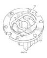
- FIG. 6is a perspective view of a valve body included in the stop-fill assembly shown in FIGS. 3 and 4 ;
- FIG. 7is an orthogonal view of the gauge assembly shown in FIG. 2 in an alternate position
- FIG. 8is an enlarged view of the area in FIG. 7 designated as 8 ;
- FIG. 9is a top view of the stop-fill assembly in a closed position
- FIG. 10is a cross-sectional view of the stop-fill assembly taken along section X-X in FIG. 9 ;
- FIG. 10Ais a partial cross-sectional view of the stop-fill assembly taken along section X-X in FIG. 9 ;
- FIG. 11is a cross-sectional view of the stop-fill assembly taken along section XI-XI in FIG. 9 ;
- FIG. 11Ais a partial cross-sectional view of the stop-fill assembly taken along section XI-XI in FIG. 9 ;
- FIG. 12is an enlarged view of the area in FIG. 10 designated as 12 ;
- FIG. 13is a top view of the stop-fill assembly in an open position
- FIG. 14is a cross-sectional view of the stop-fill assembly taken along section XIV-XIV in FIG. 13 ;
- FIG. 14Ais a partial cross-sectional view of the stop-fill assembly taken along section XIV-XIV in FIG. 13 ;
- FIG. 15is a cross-sectional view of the stop-fill assembly taken along section XV-XV in FIG. 13 ;
- FIG. 15Ais a partial cross-sectional view of the stop-fill assembly taken along section XV-XV in FIG. 13 ;
- FIGS. 16A-Dare perspective views of various valve shuttles having vanes
- FIGS. 17A-Dare perspective end views of the valve shuttles shown in FIGS. 16A-D ;
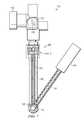
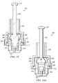
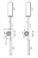
- FIG. 18is a side view of a combination service valve, stop-fill assembly, and liquid level indicator in accordance with aspects of the present disclosure
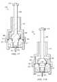
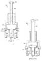
- FIG. 19is a side view of one embodiment of a stop-fill assembly in accordance with aspects of the present disclosure.
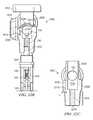
- FIG. 20is a side view of one embodiment of a service valve in accordance with aspects of the present disclosure.
- FIG. 21Ais a front perspective view of one embodiment of a removable dial in accordance with aspects of the present disclosure.
- FIG. 21Bis a rear perspective view of one embodiment of a removable dial in accordance with aspects of the present disclosure.
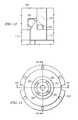
- FIGS. 22A-Bare rear views with partial cutaway showing an upper portion of a combination service valve, stop-fill assembly, and removable dial in accordance with aspects of the present disclosure
- FIG. 22Cis a cross section of a service valve modified for use with a removable dial in accordance with aspects of the present disclosure
- FIG. 23is a side view of another combination service valve, stop-fill assembly, and remote level indicator in accordance with aspects of the present disclosure.
- FIG. 24Ais an exploded view of a stop-fill assembly in accordance with aspects of the present disclosure.
- FIG. 24Bis a partial top view of the valve body of the stop-fill assembly of FIG. 24A ;
- FIG. 24Cis a partial sectional and cutaway view of the shuttle body and valve body of FIG. 24A ;
- FIG. 24Dis a partial top view of an alternate valve body for the stop-fill assembly of FIG. 24A ;
- FIG. 24Eis a partial sectional and cutaway view of the alternate shuttle body and valve body for the stop-fill assembly of FIGS. 24A and 24D ;
- FIG. 24Fis a partial side view of an alternate float assembly for use in connection with the stop-fill assembly of FIG. 24A ;
- FIG. 24Gis a partial sectional view illustrating the stop-fill assembly of FIG. 19A positioned in a tank in accordance with aspects of the disclosure
- FIG. 25is a diagram illustrating one possible correlation between the magnetic field produced by an indicator magnet and a dial pointer reading or indicator according to aspects of the present disclosure
- FIG. 26is a side view illustrating the spatial relationship between a gauge magnet and a dial magnet in accordance with aspects of the present disclosure
- FIG. 27is partial sectional, partial cut-away view of a combination stop-fill assembly in accordance with aspects of the present disclosure
- FIG. 27Ais a perspective view of the valve body and support member of the stop-fill assembly of FIG. 27 ;
- FIG. 27Bis a top view of the valve body of the stop-fill assembly of FIG. 27 ;
- FIG. 28is an enlarged portion of FIG. 27 enclosed by dashed lines in FIG. 27 ;
- FIG. 29is a partial sectional view of the stop-fill assembly of FIG. 27 taken along line 29 - 29 of FIG. 27 ;
- FIG. 30is a partial sectional view of the stop-fill assembly of FIG. 27 taken along line 30 - 30 of FIG. 27 ;
- FIG. 31is a perspective view of the valve shuttle of the stop-fill assembly of FIG. 27 ;
- FIG. 32is a top view of the valve shuttle of FIG. 31 ;
- FIG. 33is an enlarged view of the portion of FIG. 29 enclosed in dashed lines.
- FIG. 1shows a perspective view of a tank 100 having a gauge assembly 110 according to the present disclosure.
- FIG. 2shows a perspective view of the gauge assembly 110 .
- the tank 100is shown for exemplary purposes only and is in no way intended to limit the scope of the present disclosure.
- the gauge assembly 110includes a port 120 that is accessible from outside the tank 100 .
- the port 120allows fluid to be moved in and out of the tank 100 .
- the gauge assembly 110also includes an indicator 130 for providing an indication of the fluid level in the tank 100 .
- the indicator 130is a dial-type indicator, but any type of indicator could be used.
- the gauge assembly 110includes a stop-fill assembly 200 , a support member 190 , a vertical shaft 160 disposed within the support member 190 , a float 140 and a float arm 150 .
- the float 140can be made of close foam material, and the vertical shaft 160 , the support member 190 , and the float arm 150 can be made of any rigid material, including an acetal such as Delrin®.
- a distal end of the float arm 150is fixed to the float 140 , and a proximal end of the float arm 150 is connected to the vertical shaft 160 such that the float arm 150 is rotatable about the base of the vertical shaft 160 .
- the float 140moves up or down with the fluid level causing the float arm 150 to rotate about the base of the support member 190 .
- the float arm 150is shown in an alternate position in FIG. 7 .
- Rotation of the float arm 150 about the base of the support member 190causes the vertical shaft 160 to rotate about the longitudinal axis of the vertical shaft 160 .
- the rotation of the float arm 150is translated to the rotation of the vertical shaft 160 by a sector gear 170 , fixed to the proximal end of the float arm 150 , that engages a pinion gear 180 , fixed to the lower end of the vertical shaft 160 .
- the stop-fill assembly 200is fixed to an upper end of the support member 190 .
- FIG. 3shows a perspective view of the stop-fill assembly 200
- FIG. 4shows an exploded view of the stop-fill assembly 200 .
- the stop-fill assembly 200includes a valve body 210 (also shown in FIG. 6 ), a valve head 220 , and a valve shuttle 230 (also shown in FIG. 5 ), all of which can be made of any rigid material, including an acetal such as Delrin® or nylon or ultem.
- the valve shuttle 230has a shuttle body 290 that serves as a blocking member for blocking fluid flow, an upper shaft 240 that extends upwardly from the shuttle body 290 through the valve head 220 , and a lower shaft 280 that extends downwardly from the shuttle body 290 .
- a magnet 270 that serves as an indicator driving memberis fixed to an upper end of the upper shaft 240 for driving the indicator 130 .
- a tab 250is formed in the lower end of the lower shaft 280 for engaging with a slot 260 (see FIG. 8 ) formed in an upper end of the vertical shaft 160 in order to transmit rotary motion of the vertical shaft 160 to the valve shuttle 230 . As the vertical shaft 160 rotates, the magnet 270 also rotates.
- the magnet 160is coupled with a dial 370 of the indicator 130 such that the rotation of the magnet 270 causes rotation of the dial 370 according to known methods.
- the lower shaft 280also includes an opposing pair of release ribs 320 for engaging with an opposing pair of release slots 330 formed in the valve body 210 when the stop-fill assembly 200 is in a closed position.
- an indicator other than the one used in the present embodimentcan be used that does not require the presence of the magnet 270 .
- an indicator driving membersuch as an encoded disk could be used in place of the magnet 270 and an indicator could be used that optically couples with the encoded disk to translate the rotational position of the encoded disk into a fluid level.
- any kind of indicator and/or indicator driving membercan be used that translates the rotation of the upper shaft 240 into a fluid level.
- the stop-fill assembly 200includes an optional valve o-ring 300 for assisting in sealing the shuttle body 290 to a seal surface 310 of the valve body 210 when the stop-fill assembly is in the closed position.
- a seal 340can optionally be provided for assisting in sealing the juncture between the valve head 220 and the valve body 210 .
- the seal 340can be unnecessary, for example if the valve body 210 and valve head 220 are welded together, for example by ultrasonic welding.
- a spring retainer 350is provided in a through-hole in the lower shaft 280 and extends from both sides of the lower shaft 280 in order to retain an upper end of a spring 360 (see FIG. 8 ). It will be appreciated that, instead of using a separate item as the spring retainer 350 , the spring retainer 350 can instead be integrally formed in the valve shuttle 230 .
- the stop-fill assembly 200can transition between an open position and a closed position. In the open position, fluid from the port 120 can flow through the stop-fill assembly 200 , while in the closed position fluid from the port 120 is prevented from flowing through the stop-fill assembly 200 .
- a top view of the stop-fill assembly 200is provided in FIGS. 9 and 13 , where FIG. 9 shows a top view of the stop-fill assembly 200 when in the closed position, and FIG. 13 shows a top view of the stop-fill assembly 200 when in the open position.
- FIGS. 10 and 11show cross-sectional views and FIGS. 10A and 11A show partial cross-sectional views of the closed position along section lines X-X and XI-XI, respectively, of FIG. 9
- FIGS. 14 and 15provide cross-sectional views of the open position along section lines XIV-XIV and XV-XV, respectively, of FIG. 13 .
- the release ribs 320 of the valve shuttle 230ride against the upper surface of the valve body 210 .
- the release ribs 320are what keep the stop-fill assembly 200 open against the force of a fluid flow from the port 120 .
- the gauge assembly 110is in the empty position (i.e., having the float arm 150 rotated to the position corresponding with an empty condition of the tank) the release ribs 320 are at 90 degree angles to the slots, sitting on the upper surface of the valve body 210 so that the valve shuttle 230 cannot go down.
- fluid from the port 120travels downward through the space between the upper shaft 240 and the valve head 220 , around the shuttle body 290 across flow surfaces 380 , 390 , 395 , then through fill ports 410 en route to the inside of the tank 100 .
- the valve shuttle 230rotates and eventually rotates to the position shown in FIGS. 10 and 10A and FIGS. 11 and 11A where the release ribs 320 line up with the release slots 330 , which is best shown in FIG. 11 .
- the downward pressure of the fluid flowwhich is sufficient to overcome the opposing pressure of the spring 360 , causes the release ribs 320 to drop into the release slots 330 due to the force from the fluid flow.
- the shuttle body 290acts as a blocking member since the contacting surfaces of the shuttle body 290 and the valve body 210 prevent fluid from traveling from the space above the shuttle body 290 to the fill ports 410 or into the tank 100 .
- the optional valve o-ring 300assists in sealing the junction between the shuttle body 290 to the valve body 210 .
- stop-fill assembly 200is in the closed position, filling of the tank 100 is halted and at some point the source of the incoming fluid is disconnected from the port 120 or the port 120 is closed. At this point, since there is no longer any pressure against the upper side of the valve shuttle 230 , the valve shuttle 230 is moved upward under the force of the spring 360 so that the stop-fill assembly 200 transitions to the open position. This allows for fluid to exit the tank 100 by traveling back up through the stop-fill assembly 200 to the port 120 .
- the total rotation of the float arm 150 between full and empty fluid levelsis approximately 100 degrees, while the total rotation necessary for moving the valve shuttle 230 between the open position and the closed position is pinion gear 180 is close to a one to one relationship.
- the angle of the range of motion of the float arm 150can vary, for example based on the size and shape of the tank 100
- the angle of the range of motion of the valve shuttle 230can vary, for example based on the requirements of the indicator 130 .
- the relationship between the sector gear 170 and the pinion gear 180can vary so long as the relationship is such that it allows the angle of the range of motion of the float arm 150 and the angle of the range of motion of the valve shuttle 230 needed at the dial 370 of the indicator 130 to coincide.
- valve shuttle 230particularly the release ribs 320 , and the valve body 210 , particularly the upper surface thereof, from a material having a low coefficient of friction against itself, for example an acetal such as Delrin® or nylon or ultem.
- a friction-reducing material(not shown), for example a Teflon® fill material, between the release ribs 320 and the upper surface of the valve body 210 , that is made of a material having a low coefficient of friction.
- the flow surfaces 380 of the shuttle body 290are slanted such that when fluid flows across the flow surface 380 the pressure of the fluid against the slanted surface will tend to rotate the valve shuttle 230 in a predetermined direction (clockwise in the present embodiment) to help overcome the friction between the release ribs 320 and the upper surface of the valve body 210 . Also, since fluid flow into the tank 100 across the slanted flow surfaces 380 will tend to rotate the valve shuttle 230 in a predetermined direction as the tank 100 is being filled, clearances are reduced or removed between portions of various parts, such as between portions of the tab 250 and the slot 260 and between portions of engaged teeth of the sector gear 170 and the pinion gear 180 , while the tank 100 is being filled.
- the slot 260can be slightly wider than the thickness of the tab 250 to allow for the tab 250 to be longitudinally inserted and removed from the slot 260 .
- the tab 250would be free to rotate to some degree while inserted in the slot 260 . Therefore, if the valve shuttle 230 is not provided with a slanted surface such as flow surface 380 , turbulence from incoming fluid flowing across the valve shuttle 230 could cause unpredictable rotational motion of the valve shuttle 230 .
- the tab 250will be rotated, in the predetermined direction, relative to the slot 260 at or near a maximum degree allowed by the total clearance between the tab 250 and the slot 260 such that portions of the tab 250 contact portions of the slot 260 . That is, a clearance is reduced or eliminated between portions of the tab 250 and the slot 260 as fluid is flowing into the tank 100 . It will be appreciated that a clearance between portions of teeth of the sector gear 170 and the pinion gear 180 is also reduced or eliminated since the rotation of the valve shuttle 130 is transferred to push together engaging teeth of the pinion gear 180 and the sector gear 170 as fluid is flowing into the tank 100 .
- the shuttle and valvecan be designed by considering control of the pressure zones through the flow path of the valve.
- the valveis preferably designed to create low pressure zones above the shuttle and high pressure zones below the shuttle. Such a design will tend to lessen the total downward force on the shuttle thus reducing the friction working against the desired rotation of the shuttle.
- the area of flow at various points along the flow pathcan be plotted and the pressure profile determined.
- the specific design of the chamber and the shuttlecan be modified to change the pressure profile as desired.
- vanescan be provided on the valve shuttle of a predetermined shape and size to impart the desired rotational force to the valve shuttle in a predetermined direction.
- FIGS. 16A-Dillustrated various configuration of vanes
- FIGS. 17A-Dare end views of the respective figures in FIGS. 16A-D . Any desired shape of the vanes can be utilized, and while all of the illustrated vanes extend from the surface of the shuttle, it will be appreciated that vanes could be supplied in the form of grooves in the shuttle.
- FIGS. 16A and 17Ashow vanes 400 having a uniform thickness and having a substantially flat front side surface 402 and a substantially flat rear side (not shown). Vanes 400 are set at a predetermined angle 406 to shuttle axis 408 .
- FIGS. 16B and 17Bshow vanes 411 in the shape of a curved plate of substantially uniform thickness and having a curved front side 412 and a curved rear side 414 . The front and rear sides can be oriented such that they are substantially parallel to the shuttle axis 408 .
- FIGS. 16C and 17Dillustrate vanes 420 having a substantially uniform thickness and having a flat front side 422 and a flat rear side 424 .
- the vaneshave a longitudinal axis 426 which is perpendicular to the shuttle axis 408 and set off the shuttle axis a predetermined distance 428 .
- FIGS. 16D and 17Dillustrate vanes 430 having a substantially uniform cross-section and a curved front side 432 and a curved rear side 434 .
- the inner end 436 of vanes 432is adjacent to the shuttle axis 408 and surfaces of the front and rear side 432 and 434 are parallel to axis 408 .
- the base where the vanes attach to the shuttlecan be thicker than the other end.
- the flow of fluid across the vanesmay assist in rotating the valve shuttle from the open position to the closed position.
- the vanescan be shaped such that the thickness of the vanes varies in the shape of an airfoil.
- the spring 360allows for the stop-fill assembly 200 to remain in the open position when not under the pressure of incoming fluid. However, in some cases the pressure of fluid in the tank 100 is sufficient to cause the valve shuttle 230 to move to the open position when the port 120 is open so that even without the spring 360 fluid can be removed from the tank 100 .
- a spiral gauge having a float on the vertical shaft 160where the vertical shaft 160 has a ramp going up such that, as the float moves up and down the vertical shaft 160 , the shaft 160 rotates.
- the devicecould be modified to eliminate the indicator or the stop-fill function.
- the valve shuttle 230could be replaced with a shaft so that the gauge assembly drives the indicator 130 but does provide stop-fill functionality.
- the indicator 130 and magnet 270could be eliminated so that the gauge assembly has stop-fill functionality but not an indicator.
- a service valve assembly 1805connects to a stop-fill assembly 1810 .
- a dial 1815is also provided and interconnects with the service valve assembly 1805 .
- the dialmay be removable and reattachable by the user, while in other embodiments the dial may be permanently or semi-permanently affixed to the service valve.
- the service valve assembly 1805provides a port 120 in a valve outlet 1802 .
- the service valve assembly 1805also provides port threads 1814 .
- the port threads 1814may be used to interconnect the service valve assembly 1805 with an external device such as a filling device or appliance.
- a tank connection 1820( FIG. 20 ) is also provided for connecting with a tank such as the tank 100 shown in FIG. 1 .
- the tank connection 1820may provide tank connection threads 1822 .
- the threads 1822will mate with threads provided on the tank 100 .
- a service valve knob 1812is also shown in the embodiment of FIG. 18 .
- the service valve knob 1812may be used to allow or restrict the flow of gas through the service valve assembly 1805 .
- the stop-fill assembly 1810is similar in many respects to the stop-fill devices that have been previously described herein.
- a support member 190secures a rotatable vertical shaft 160 that attaches to a pinion gear 180 .
- the pinion gear 180engages a sector gear 170 which attaches to a float arm 150 .
- a float 140is provided at one end of the float arm 150 .
- a counter balance 1825is provided at the end of the float arm 150 opposite the float 140 .
- the counter balance 1825may serve to decrease the resistance to movement that may be encountered internally in the stop-fill assembly 1810 . Additionally, as can be seen in FIG. 18 , the counter-balance 1825 may serve to prevent an over rotation of the float arm 150 via its interference with the support member 190 .
- the vertical shaft 160rotates in response to movement of the float 140 .
- the rotation of the vertical shaft 160drives the fluid stopping mechanisms of the stop-fill assembly 1810 .
- Such mechanismshave been previously described with respect to other embodiments and therefore will not be repeated here.
- the vertical shaft 160also provides rotation of a magnet ( FIG. 19 ) that drives the gauge dial assembly 1815 .
- FIG. 19a side view of one embodiment of a stop-fill assembly suitable for use in a combination service valve stop-fill assembly is shown.
- the stop-fill assembly 1900may be internally the same as those that have been previously described or it may be internally similar to those further described herein.
- an upper shaft 240can be seen connecting to a magnet 270 .
- a valve head 220 of the stop-fill assembly 1900is provided with threads 1910 .
- the threads 1910provide a secure means allowing the stop-fill assembly 1900 to connect with the lower service valve port 1820 of the service valve assembly 1805 .
- FIG. 20a perspective view of one embodiment of a service valve suitable for use in a combination service valve stop-fill is shown.
- the service valve assembly 1805is shown separated from the dial 1815 and the stop-fill assembly 1810 .
- FIG. 20illustrates the presence of the port 120 and tank connection 1820 which may be threaded with threads 1810 and 1822 , respectively.
- the service valve knob 1812may be provided to allow opening and closing of the service valve assembly 1805 .
- the service valve knob 1812will typically sit atop the valve body 2020 .
- the valve body 2020also connects to the valve outlet 1802 , the tank connection 1820 , and a pressure relief valve 2022 .
- a set of wrench flats 2005 and 2205are provided on the service valve 1805 near the junction of the valve body 2020 and the tank connection 1820 .
- the wrench flat 2005is shown with a recess 2010 provided therein.
- the service valve 1805is a standard, commercially available brass service valve.
- the recess 2010can be machined directly into the wrench flat 2005 .
- a standard service valve 1805can be adapted for use with aspects of the present disclosure.
- the recess 2010will be round but in other embodiments different shapes can be used.
- the depth of the recess 2010 relative to the wrench flat 2005will be approximately 0.2 inches. As can be better appreciated from the drawings that follow, this will allow a dial magnet inserted sufficiently into the recess 2010 to interact with magnet 170 to provide readings on the gauge dial 1815 . In other embodiments, magnets 270 and 2152 ( FIG. 21B ) are sufficiently strong that a recess 2010 is not needed.
- FIG. 21Aa perspective view of the front side of one embodiment of a removable dial suitable for use in a combination service valve stop-fill apparatus in accordance with aspects of the present disclosure is shown.
- the dial 1815provides a dial face 2110 .
- the dial face 2110may be molded plastic or another suitable material.
- a lens 2115may be provided.
- the lens 2115may be glass or plastic or another suitably transparent material. It can be seen that the lens 2115 provides protection for the pointer 2130 as well as the indicator markings 2120 .
- the indicator markings 2120may be painted or molded onto the dial face 2110 . In the embodiment of FIG. 21A markings corresponding to empty, half-full and full are shown but in other embodiments other markings may be used.
- the lens 2115provides clearance for the pointer 2130 to sweep along the dial face 2110 to point to or near the corresponding indicator markings 2120 .
- the pointer 2130is driven by an internal magnet 2152 ( FIG. 21B ).
- One or more spring clips 2140may be seen protruding from the side of the gauge dial face 2110 opposite the pointer 2130 .
- the spring clip 2140may be provided to aid in alignment and/or attachment of the dial 1815 to the service valve assembly 1805 .
- FIG. 21Ba perspective view of the back side of one embodiment of a removable dial 1815 in accordance with aspects of the present disclosure is shown.
- FIG. 21Bprovides a view of the dial 1815 illustrating one possible placement of the spring clip 2140 .
- the spring clip 2140may be attached to the backside of the dial face 2110 by a number of means including, but not limited to, snap fittings, friction fittings, gluing or molding.
- the spring clip 2140may be molded from the same plastic as the dial face 2110 .
- the spring clip 2140may be another suitably resilient metal.
- Also protruding from the dial face 2110 on the backsideis a dial magnet housing 2150 .
- the dial-magnet housingprovides clearance and covering for the magnet 2152 that drives the pointer 2130 .
- FIGS. 22A and 22Brear views with partial cutaways showing an upper portion of a combination service valve, stop-fill assembly, and removable dial in accordance with aspects of the present disclosure is shown.
- the service valve assembly 1805provides two wrench flats 2005 and 2205 .
- the wrench flats 2005 and 2205may provide parallel flat surfaces.
- the wrench flats 2005 and 2205may be used to aid in the insertion of the valve assembly 1805 into a tank such as the tank 100 of FIG. 1 .
- the recess 2010is also shown in dotted line within the wrench flat 2005 .
- a lower service valve throat 2210is shown in outline and provides throat threads 2212 .
- FIG. 22Ait can be seen how the various components of the assembly combination of FIGS. 22A and 22B may be assembled.
- the dial 1815may be attached to the service valve 1805 by inserting the dial magnet housing 2150 securely into the recess 2010 on the wrench flat 2005 .
- the dial 1815may be sufficiently secured to the service valve assembly 1805 by the friction between the dial magnet housing 2150 and the recess 2010 .
- spring clipssuch as shown in FIGS. 21A and 21B may be used to stabilize and/or sufficiently secure the dial 1815 to the service valve assembly 1805 .
- the magnet 270 attached to the end of the upper shaft 240can be inserted into the lower service valve throat 2210 .
- the threads 1910 of the valve head 220may be adapted to interfit with the throat threads 2212 such that when the magnet 270 is inserted into the lower service valve throat 2210 as shown by the arrow B, the magnet 270 is in relatively close proximity to the magnet inside the dial magnet housing 2150 .
- Rotation of the magnet 270 about a generally vertical axisi.e., the axis of rotation of shaft 240 ) causes variations of the associated flux field about the vertical axis.
- This flux fieldinteracts with the flux field associated with the dial magnet 2152 to cause rotation of the dial magnet about a generally horizontal axis (i.e., the axis of rotation of the dial pointer 2130 ).
- a rotation of the magnet 270translates into movement of the pointer 2130 .
- the rotation of the shaft 240 and magnet 270is substantially orthogonal to the direction of rotation of the dial pointer 2130 .
- the axesneed not necessarily be horizontal and vertical.
- FIG. 22Bshows the assembled combination of the service valve assembly 1805 , the dial 1815 , and the stop-fill assembly 1810 .
- the dial 1815is securely fastened to the service valve assembly 1805 by having had the dial magnet housing 2150 inserted into the recess 2010 .
- the magnet 270is rotatable in close proximity to the dial magnet housing 2150 . As the magnet 270 rotates in response to movements of the float 140 , such movements may be indicated on the face of the dial 1815 via magnetic interaction between the magnet 270 and the magnet contained within the dial 1815 .
- FIG. 22Cis a cross section of a service valve 1805 modified for use with a removable dial in accordance with aspects of the present disclosure.
- the service valve 1805 in FIG. 22Cis shown without the stop-fill assembly 1810 , dial 1815 , or knob 1812 .
- the placement of the lower service valve throat 2210 relative to the wrench flats 2005 and 2205can be seen from this view. It can also be seen that the lower service valve throat 2210 extends into an interior chamber 2230 of the service valve 1805 .
- the interior chamber 2230allows fluids and/or gases to pass from the port 120 to the lower service valve throat 2210 .
- the service valve 1805when fully assembled and operational, provides means that are known in the art for selectively allowing fluid and gaseous transfer from the port 120 through the lower service valve throat 2210 .
- the primary modification to the service valve 1805includes machining or drilling a recess 2010 into one of the wrench flats 2005 , 2205 .
- the recess 2010could be cast directly into the service valve 1805 , or created by other means.
- the recess 2010is prepared in the wrench flat 2005 .
- FIG. 23is a side view of another combination service valve, stop-fill assembly, and liquid level indicator in accordance with aspects of the present disclosure.
- the combination 2300is similar to the combination 1800 ( FIG. 18 ) previously described. However, in place of the gauge dial 1815 , the combination 2300 provides a magnetic field sensor 2310 .
- the magnetic field sensor 2310senses the intensity and direction of the magnetic field produced by the magnet 270 ( FIG. 19 ).
- the magnetic field sensorwill be a two pole analog magnetic sensor such as the TESLA3 from the Asahi Kasei Corporation of Osaka, Japan.
- the magnetic field sensor 2310may convey data corresponding to the position of the magnet 270 to a remote location.
- the field sensor 2310could convey data wirelessly or may convey data through one or more electrical leads 2313 , as shown. Two leads are shown but more or fewer could be used depending upon the field sensor 2310 being used.
- a dial or indicator 2320may provided at a remote location for viewing information corresponding to the position of the magnet 270 .
- the electrical signals provided wirelessly or via the leads 2313will be processed into a liquid level reading such as a fuel level. Processing or signal conditioning may take place locally or remotely (e.g., at the sensor 2310 or at or near the indicator 2320 ).
- the indicator 2320will provide readouts from multiple locations or gauges. The readout on the indicator 2320 is shown in a digital format but could also be in an analog format, possibly similar in appearance to the gauge dial 1815 ( FIG. 18 ).
- FIG. 24Ais an exploded view of a stop-fill assembly in accordance with aspects of the present disclosure.
- the stop-fill assembly 1810may be used in a combination device such as those shown in FIGS. 18-19 .
- the stop-fill assembly 1810is similar in some respects to the stop-fill assemblies previously described herein.
- a support member 190is provided with a vertical shaft 160 disposed within.
- a float arm 150is connected to the support member 190 so as to be able to rotate thereon.
- An eyelet 2316may be provided as a fastener between the support member 190 and the float arm 150 .
- the float arm 150is also connected at opposite ends to a float 140 and a counter balance 1825 .
- Rotation of the float arm 150 about the base of the support member 190causes the vertical shaft 160 to rotate about the longitudinal axis of the vertical shaft 160 .
- the rotation of the float arm 150may be translated to the rotation of the vertical shaft 160 by a sector gear 170 , fixed to the proximal end of the float arm 150 that engages a pinion gear 180 , fixed to the lower end of the vertical shaft 160 .
- the stop-fill assembly 1810also includes a valve body 210 and a valve head 220 .
- a shuttle body 290serves as a blocking member for blocking fluid flow.
- An upper shaft 240extends upwardly from the shuttle body 290 through the valve head 220 . If desired, an eyelet 2311 may be provided for increasing the durability or structural integrity of the valve head 220 .
- a magnet, 270 that serves as an indicator driving member,is fixed to an upper end of the upper shaft 240 .
- a tab 250is formed below the shuttle body 290 on a lower shaft 280 . The tab 250 interfits with the slot 260 of the vertical shaft 160 in order to transmit rotary motion of the vertical shaft 160 to the shuttle body 290 .
- the tab 250may be free to slide vertically within the slot 260 such that the lower shaft 280 and connected shuttle body 290 can move vertically independent of the vertical shaft 160 .
- the lower shaft 280also includes an opposing pair of release ribs 320 for engaging with an opposing pair of release slots 330 formed in the valve body 210 when the stop-fill assembly 200 is in a closed position.
- a bearing clip 2314may be provided between the valve body 210 and the release ribs 320 to increase the durability and decrease the friction of the contact between the release ribs and the valve body.
- the bearing clip 2314may be composed of a metal, a low friction plastic, a polymer, or other substance.
- the stop-fill assembly 1810can transition between an open position and a closed position. In the open position, fluid (e.g., from the port 120 ) can flow through the stop-fill assembly 1810 , while in the closed position fluid is prevented from flowing through the stop-fill assembly 1810 .
- the release ribs 320 of the valve shuttle 230ride against the upper surface of the valve body 210 or the bearing clip 2314 .
- the release ribs 320keep the stop-fill assembly 200 open against the force of a fluid flow (e.g., from the port 120 ).
- the release ribs 320are at 90 degree angles to the slots 330 , sitting on the upper surface of the valve body 210 so that the valve shuttle body 290 cannot go down. In this configuration, fluid travels downward through the space between the upper shaft 240 and the valve head 220 , around the shuttle body 290 , through fill ports 410 and out through ports 2340 formed through the sides of valve body 210 .
- FIG. 24Bis a partial top view of the valve body 210 of FIG. 24A with release ribs 320 at 90 degree angles to slots 330 , sitting on the surface of valve body 210 (and bearing 2314 ) so that the valve shuttle body is in the open position.
- FIG. 24Cis a partial sectional and partial cutaway view of the shuttle body 290 engaged in the valve body of FIG. 24A . In the open position, fluid travels downward through the space between the upper shaft 240 and the valve head 220 , around the shuttle body 290 and through discharge ports 2340 formed in valve body 210 and into the container (e.g., tank 100 ).
- the containere.g., tank 100
- ports 2340direct fluid entering tank 100 through the stop-fill device 1800 radially away from a central longitudinal axis of tank and likewise away from shaft 160 . Discharging fluids through radially directed ports 2340 reduces the amount of turbulence generated in tank 100 during the filling operation along with possible impingement of the fluid onto float 140 or float arm 150 which can interfere with the operation of the float.
- the shuttle body 190rotates and eventually rotates to the closed position.
- the downward pressure of the fluid flowwhich is sufficient to overcome the opposing pressure of the spring 360 , causes the release ribs 320 to drop through the bearing clip 2314 and into the release slots 330 .
- the shuttle body 290then acts as a blocking member.
- a beveled circumferential surface 2342 of shuttle body 290seats against a corresponding beveled surface or seat 2344 of valve body 210 to block the flow of fluid through the stop-fill assembly 1810 .
- shuttle body 290can move up and down in the longitudinal direction even though the vertical shaft 160 is fixed in the longitudinal direction, while at the same time the shuttle body remains rotationally engaged with the vertical shaft such that the shuttle body and vertical shaft always rotate together.
- shuttle body 290rotates in response to the rotation of shaft 160 , but translates longitudinally independent of shaft 160 when moving between the open and closed positions.
- a separate spring clip 2312( FIG. 24A ) is provided for stabilizing the spring 360 against the valve body 210 and for preventing binding of the spring when the vertical shaft 160 rotates.
- the relatively short distance that the shuttle body 290 travels when moving into the closed positionmeans that the vertical translation of the magnet 270 is also relatively small. Therefore the magnetic field produced by the magnet 270 does not change substantially, and thus the movement of the magnet 270 along the axis of the stop-fill assembly 1810 has no substantial bearing on the interaction of the magnet 270 and the pointer magnet 2152 . It is the rotational movement of the magnet 270 that produces a change in the magnetic flux field that may be recognizable by the dial 1815 as a change in the fluid level of the tank 100 .
- stop-fill assembly 1810is in the closed position, filling is halted.
- the source of the incoming fluidis disconnected from the port 120 or the port 120 is closed.
- the valve shuttle body 290is moved upward under the force of the spring 360 so that the stop-fill assembly 1810 transitions to the open position. This allows for fluid or gas to exit the tank 100 by traveling back up through the stop-fill assembly 1810 to the port 120 .
- FIG. 24Dis a top view of an alternate valve body 2350 and FIG. 24E is a partial cutaway and partial sectional view of a corresponding shuttle body 2352 .
- release ribs 320have been replaced with a pair of release arms 2354 that extend outward from an upper surface of shuttle body 2352 and downward to a surface 2356 of valve body 2350 outside of beveled valve seat 2344 .
- a pair of release apertures 2358 formed in surface 2356receive the distal ends 2360 of arms 2354 , permitting the shuttle body to move downward when arms 2354 are moved into alignment with apertures 2358 .
- FIG. 24Fis a side view of an alternate float assembly 2380 for use with stop-fill assembly 1810 .
- Float assembly 2380includes a float arm 2382 , a float 2384 attached to a first end of arm 2382 and a counterweight or counterbalance 2386 attached to a second end of arm 2382 .
- Float arm 2382is operatively connected to a sector gear 170 which drives pinion gear 180 that is attached to vertical shaft 160 .
- float 2384is mounted on arm 2382 such that the float is offset from the longitudinal axis of the float arm such that a longitudinal axis of the float extends below the float arm when the float arm is in a horizontal orientation.
- float 2384is slanted downward at an angle ⁇ from about 10 degrees to about 45 degrees relative to a longitudinal axis 2388 of arm 2382 . It was found that angling float 2384 relative to the longitudinal axis of arm 2382 in this manner improved the efficiency of the float and increased the sensitivity of the assembly to changes in liquid level in tank 100 at near full volumes or at volumes where the angle of the longitudinal axis 2388 of arm 2382 relative to horizontal approaches 90 degrees.
- float 2384may be offset from the longitudinal axis of arm 2384 by forming a bend in the arm adjacent to the float, offsetting the float on the arm or using an extension of the arm that offsets the float.
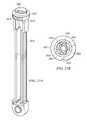
- FIG. 24Gis a partial sectional view illustrating the stop-fill assembly 1810 of FIG. 24A positioned in pressurized tank 100 .
- tank 100includes a cylindrical sidewall 102 defining a central axis 104 extending therethrough, a generally semi-cylindrical top wall 106 , a generally semi-cylindrical bottom wall 108 and a shield 112 extending at least partially around a service valve 2700 suitable for use in connection with stop-fill devices described herein.
- service valve 2700includes a valve inlet/outlet 1802 through which tank 100 is filled and emptied, a relief valve 2022 , and a threaded tank connection 1820 that is screwed into a threaded opening 122 in top wall 106 of the tank.
- tank 100will have only one such opening 122 through which the tank is filled and emptied. Since tank 100 is filled and emptied through opening 122 , stop-fill assembly 1810 must function as a two way valve as described herein.
- a handle 1812is provided for opening and closing service valve 2700 .
- Tank 100is suitable for containing a pressurized fluid 114 such as liquefied natural gas (LNG), liquefied propane and/butane and similar volatile liquefied gases commonly used for cooking and heating.
- a pressurized fluid 114such as liquefied natural gas (LNG), liquefied propane and/butane and similar volatile liquefied gases commonly used for cooking and heating.
- Tank 100may be filled with such liquefied gases through service valve 2700 and stop-fill assembly 1810 which blocks flow of the liquefied gas when the amount of fluid 114 reaches a predetermined level corresponding to a desired volume of pressurized fluid 114 in tank 100 and then reopens when the fill source is disconnected and pressure across the stop-fill assembly is equalized such that spring 360 ( FIG.
- pressurized fluid 114 entering tank 100flows through radially directed ports 2340 which direct fluid entering the tank away from longitudinal axis 104 of tank 100 in the direction of arrows 124 .
- the amount of turbulence generated on the surface of the fluid 114 in tank 100 during the filling operationis reduced.
- Possible direct impingement of fluid 114 onto float 140 , float arm 150 and/or counter balance 1825is eliminated or substantially reduced. Reducing surface turbulence and/or impingement on the float arm reduces the likelihood of premature activation of the stop-fill device, which could result in incomplete filling.
- FIG. 25is a diagram illustrating one possible correlation between the magnetic field produced by an indicator magnet and a dial reading according to aspects of the present disclosure.
- Relative field intensitiesin both N and S
- directions correspondent to degrees of rotation of the magnet 270 from a starting pointare labeled for illustration.
- FIGS. 19 and 24it can be seen that the orientation of the magnet 270 changes in response to a level of the float 140 on the float arm 150 .
- the magnet 270will have a north pole and a south pole and will produce a magnetic field in proximity thereto that will vary in strength and direction.
- the float arm 150 and pinion gear 180can be configured to provide a rotation of the magnet 270 starting from a known position (e.g., empty) and proceeding to another known position (e.g., full) in a known ratio.
- a known positione.g., empty
- another known positione.g., full
- the diagram of FIG. 25illustrates that in one embodiment, only a portion of the field strengths and directions possible from the magnet 270 may be used in order to simplify calibration and readings.
- the magnetic field strength and directiontakes on each possible value or a subset of possible values only once.
- the range Ror in the present embodiment, subset thereof, G, may be used over the range of possible fluid levels in the container (e.g., tank 100 ). Possible markings for a gauge dial or other indicator corresponding to the field values over the range G are shown in FIG. 25 for illustration.
- FIG. 26a side view 2900 of the spatial relationship between a gauge magnet and a dial magnet according to aspects of the present disclosure is shown.
- the diagram 2900could correspond to the relationship between the magnet 270 and the pointer magnet 2152 when in use with any of the gauge and dial combinations described herein, whether a stop-fill device is included in the combination or not.
- the magnet 270attached to the upper shaft 240 and rotates about the axis 2910 of the shaft 240 .
- a plane 2912is defined.
- the plane 2912is represented in dotted line.
- a rotation of the magnet 270 about its axis 2910causes a corresponding rotation of the pointer magnet 2152 about its axis 2914 .
- the axes 2910 and 2914are generally orthogonal. In some embodiments or applications, one axis will be vertical while the other is horizontal but this is not required. However, in some embodiments, an offset between the plane of rotation 2912 of the magnet 270 and the axis 2914 of rotation of the pointer magnet 2152 will be provided. This allows increased leverage in the magnetic flux between the magnets 270 and 2152 to ensure adequate rotation of the pointer magnet 2152 by the magnet 270 .
- the offsetcan vary by application and depending upon the range of motion needed in the pointer 2130 . The offset could also be in either direction i.e., above or below the axis 2914 along the shaft axis 2910 .
- FIG. 27is a partial section, partial cut-away view of a combination gauge and stop-fill valve assembly 3000 suitable for use with a tank such as tank 100 ( FIG. 24G ) containing a pressurized fluid such as liquefied natural gas (LNG), liquefied propane and/butane and similar volatile liquefied gases commonly used for cooking and heating.
- Stop-fill valve assembly 3000includes a valve body 3002 and a valve head 3004 configured to extend into the lower throat 3006 of a service valve 3008 .
- Valve head 3004 and throat 3006may be provided with threads (not shown) for connecting stop-fill assembly 3000 to the service valve.
- a support member 3010extends downwardly from valve body 3002 with a vertical shaft 3012 rotatably disposed within the support member.
- a float arm 3014is connected to the distal end of support member 3010 for rotation about the distal end of the support member in response to changes in the fluid level in tank 100 .
- a float 3016is connected to a first end of float arm 3014 with a counterbalance 3018 attached to a second end of the float arm remote from the float.
- Float 3016moves in response to changes in the fluid level in tank 100 , causing float arm 3014 to rotate around the distal end of support member 3010 .
- Rotation of float arm 3014is transmitted to vertical shaft 3012 by means of a sector gear 3022 attached to the float arm that engages a pinion gear 3024 mounted on the distal end of vertical shaft 3012 to rotate the shaft.
- the upper or proximate end of vertical shaft 3012engages valve shuttle 3026 , e.g., by means of the tab-and-slot arrangement shown in FIG. 24A , to rotate the shuttle in response to changes in the fluid level in tank 100 .
- valve body 3002includes fill ports 3020 that communicate with radial ports 3076 to allow fluid to flow into and out of tank 100 .
- radial ports 3076are directed radially away from and generally perpendicular to the longitudinal axis of support member 3010 to direct fluid entering tank 100 away from float 3016 , float arm 3014 or counterbalance 3018 .
- the radial orientation of ports 3076prevents or minimizes impingement of fluid entering tank 100 on float 3016 , float arm 3014 or counterbalance 3018 and/or turbulence that may interfere with the operation of stop-fill assembly 3000 .
- valve shuttle 3026includes an upper shaft 3028 with a magnet holder 3031 formed on the distal end of the upper shaft, a shuttle body 3032 and a lower shaft 3034 .
- Upper and lower shafts 3028 , 3034each extend along a longitudinal axis 3036 of valve shuttle 3026 .
- Shuttle body 3032includes a generally conical upper wall 3033 with a plurality of ribs 3038 extending outwardly from the upper wall.
- a pair of release ribs 3030extend radially outward from the proximate end of lower shaft 3034 and downwardly from shuttle body 3032 . Release ribs 3030 bear against valve body 3002 to support valve shuttle 3026 when stop-fill assembly 3000 is in the open position.
- a spring clip 3046prevents spring 3044 from binding as vertical shaft 3012 and shuttle body 3032 rotate.
- valve shuttle 3026is disposed on valve body 3002 with upper shaft 3028 positioned in valve head 3004 .
- Shuttle body 3032is positioned inside a valve chamber 3048 including an upper, generally conical wall 3050 , a cylindrical side wall 3052 and a bottom wall 3054 .
- ribs 3038act as stops, limiting upward travel of shuttle body 3032 in valve chamber 3048 by contacting conical wall 3050 of the chamber.
- a passage 3056 formed through bottom wall 3054has opposed release slots 3058 extending therefrom for receiving release ribs 3030 when valve shuttle 3026 rotates to a position where the release ribs are aligned with the release slots.
- Lower shaft 3034extends through a central portion of passage 3056 to engage the proximate end of vertical shaft 3012 .
- a beveled sealing surface or valve seat 3060 formed in bottom wall 3054seals against a corresponding beveled sealing surface 3062 ( FIG. 31 ) that extends circumferentially around the lower edge of shuttle body 3032 when shuttle body 3032 translates into the closed position.
- the distance between valve seat 3060 and sealing surface 3062 when stop-fill assembly 3000 is in the open positionmay be determined by the length of release ribs 3030 that support valve shuttle 3026 .
- stop-fill assembly 3000operates in essentially the same manner as described in connection with embodiments disclosed above.
- Service valve 3008is connected to a source of LNG or LPG and opened.
- the LPGflows through service valve 3008 into an annular space 3064 between valve head 3004 and upper shaft 3028 and into valve chamber 3048 .
- the LPGflows around shuttle body 3032 , between valve seat 3060 and sealing surface 3062 and through fill ports 3020 , discharging into tank 100 through radial ports 3076 .
- lifting float 3016 , float arm 3014rotates around the distal end of support member 3010 .
- Sector gear 3022rotates with float arm 3014 , turning pinion gear 3024 and vertical shaft 3012 .
- Valve shuttle 3026rotates with vertical shaft 3012 until release ribs 3030 move into alignment with release slots 3058 .
- release ribs 3030are aligned with release slots 3058
- the downward force on valve shuttle 3026 exerted by LPG flowing over shuttle body 3032overcomes the biasing force of spring 3044 , causing the shuttle to translate longitudinally with the release ribs entering the release slots.
- Sealing surface 3062 of shuttle body 3026moves into abutment with valve seat 3060 , closing off the flow of LPG through stop-fill assembly 3000 .
- spring 3044pushes the valve shuttle up, returning the valve to the open position.
- Stop-fill valve 3000relies on the force exerted on valve shuttle 3026 to close the valve when a fluid in the tank such as LNG or LPG reaches a predetermined level, for example 80% of the capacity of the tank.
- the force applied to valve shuttle 3026is therefore dependent upon the rate of fluid flow and the differential pressure across the valve.
- LPGis a volatile material having a vapor pressure that varies considerably with temperature.
- the vapor pressure of 100% propanevaries from 24.5 psig at 0 degrees F. to approximately 177 psig at 100 degrees F. Consequently, the pressure differential across stop-fill valve 3000 when filling tank 100 with LPG may vary considerably depending upon factors such as ambient temperature, pump pressure and the composition of the LPG (e.g., % propane). In view of these variations, it is desirable that stop-fill valve 3000 close quickly and reliably at relatively low differential pressures across the valve.
- stop-fill valve 3000is configured with a maximum upper flow area 3070 when the valve is in the open position.
- upper flow area 3070is the cross-sectional area between conical upper wall 3033 of shuttle body 3032 and conical wall 3050 of valve chamber 3048 taken along line 30 - 30 of FIG. 28 .
- a lower flow area 3072is the area between valve seat 3060 of valve body 3002 and the corresponding sealing surface 3062 of shuttle body 3032 when the valve is in the open position.
- the size of lower flow area 3072may be increased or decreased by adjusting the length of release ribs 3030 which support valve shuttle 3026 when stop-fill valve 3000 is in the open position.
- a swept surface area 3074corresponds to the surface area of the conical upper wall 3033 of shuttle body 3032 .
- the ratio of the upper flow area 3070 to the lower flow area 3072is approximately 1.8 to about 3.5 with the ratio of the swept surface 3074 to the lower flow area 3072 ranging from about 1.3 to about 2.5.
- the ratio of the upper flow area 3070 to the lower flow area 3072is approximately 2.5 to about 3.0 with the ratio of the swept surface 3074 to the lower flow area 3072 ranging from about 1.5 to about 2.0.
- the ratio of the upper flow area 3070 to the lower flow area 3072is approximately 2.9 with the ratio of the swept surface area 3074 to the lower flow area 3072 approximately 1.8.
Landscapes
- Engineering & Computer Science (AREA)
- General Engineering & Computer Science (AREA)
- Mechanical Engineering (AREA)
- Mechanically-Actuated Valves (AREA)
- Indication Of The Valve Opening Or Closing Status (AREA)
Abstract
Description
Claims (20)
Priority Applications (5)
| Application Number | Priority Date | Filing Date | Title |
|---|---|---|---|
| US11/840,915US7726334B2 (en) | 2004-01-22 | 2007-08-17 | Service valve assembly having a stop-fill device and remote liquid level indicator |
| EP07814239AEP2059701A2 (en) | 2006-08-18 | 2007-08-18 | Service valve assembly having a stop-fill device and remote liquid level indicator |
| US12/377,993US20100229964A1 (en) | 2006-08-18 | 2007-08-18 | Service valve assembly having a stop-fill device and remote liquid level indicator |
| PCT/US2007/076256WO2008022340A2 (en) | 2006-08-18 | 2007-08-18 | Service valve assembly having stop-fill device and remote liquid level indicator |
| MX2009001828AMX2009001828A (en) | 2006-08-18 | 2007-08-18 | Service valve assembly having a stop-fill device and remote liquid level indicator. |
Applications Claiming Priority (7)
| Application Number | Priority Date | Filing Date | Title |
|---|---|---|---|
| US53827904P | 2004-01-22 | 2004-01-22 | |
| US57214304P | 2004-05-18 | 2004-05-18 | |
| US11/023,664US7293578B2 (en) | 2004-01-22 | 2004-12-28 | Gauge assembly having a stop fill device |
| US82292106P | 2006-08-18 | 2006-08-18 | |
| US82292606P | 2006-08-18 | 2006-08-18 | |
| US82292806P | 2006-08-19 | 2006-08-19 | |
| US11/840,915US7726334B2 (en) | 2004-01-22 | 2007-08-17 | Service valve assembly having a stop-fill device and remote liquid level indicator |
Related Parent Applications (1)
| Application Number | Title | Priority Date | Filing Date |
|---|---|---|---|
| US11/023,664Continuation-In-PartUS7293578B2 (en) | 2004-01-22 | 2004-12-28 | Gauge assembly having a stop fill device |
Publications (2)
| Publication Number | Publication Date |
|---|---|
| US20080035213A1 US20080035213A1 (en) | 2008-02-14 |
| US7726334B2true US7726334B2 (en) | 2010-06-01 |
Family
ID=39049411
Family Applications (1)
| Application Number | Title | Priority Date | Filing Date |
|---|---|---|---|
| US11/840,915Expired - LifetimeUS7726334B2 (en) | 2004-01-22 | 2007-08-17 | Service valve assembly having a stop-fill device and remote liquid level indicator |
Country Status (1)
| Country | Link |
|---|---|
| US (1) | US7726334B2 (en) |
Cited By (15)
| Publication number | Priority date | Publication date | Assignee | Title |
|---|---|---|---|---|
| US20090301585A1 (en)* | 2008-06-09 | 2009-12-10 | William Home | Gas meter of gas canister valve |
| US20090301574A1 (en)* | 2008-06-09 | 2009-12-10 | William Home | Mechanism for controlling a gauge for indicating the amount of gas remaining in a gas tank |
| US20110197994A1 (en)* | 2008-06-09 | 2011-08-18 | William Home | Mechanism for controlling a gauge for indicating the amount of gas remaining in a gas tank |
| US20120260730A1 (en)* | 2011-04-15 | 2012-10-18 | Rochester Gauges, Inc. | Liquid Level Sender with Adjustable Counterweight |
| US8950019B2 (en) | 2007-09-20 | 2015-02-10 | Bradley Fixtures Corporation | Lavatory system |
| US8997271B2 (en) | 2009-10-07 | 2015-04-07 | Bradley Corporation | Lavatory system with hand dryer |
| US9170148B2 (en) | 2011-04-18 | 2015-10-27 | Bradley Fixtures Corporation | Soap dispenser having fluid level sensor |
| US9267736B2 (en) | 2011-04-18 | 2016-02-23 | Bradley Fixtures Corporation | Hand dryer with point of ingress dependent air delay and filter sensor |
| US9714717B2 (en) | 2013-08-06 | 2017-07-25 | Fluid Handling Llc | Flow switch assembly featuring two-part base assembly with non-metallic upper part and metallic lower part |
| US9758953B2 (en) | 2012-03-21 | 2017-09-12 | Bradley Fixtures Corporation | Basin and hand drying system |
| US10041236B2 (en) | 2016-06-08 | 2018-08-07 | Bradley Corporation | Multi-function fixture for a lavatory system |
| US10100501B2 (en) | 2012-08-24 | 2018-10-16 | Bradley Fixtures Corporation | Multi-purpose hand washing station |
| US11015329B2 (en) | 2016-06-08 | 2021-05-25 | Bradley Corporation | Lavatory drain system |
| US11898655B2 (en) | 2021-07-22 | 2024-02-13 | Ysn Imports, Llc | Tank valve system with combined overfill prevention and fuel level indication |
| US20240255339A1 (en)* | 2023-01-26 | 2024-08-01 | Delphi Technologies Ip Limited | Reinforcement support brace for a float arm |
Citations (240)
| Publication number | Priority date | Publication date | Assignee | Title |
|---|---|---|---|---|
| US23816A (en) | 1859-05-03 | Alarm water-gage | ||
| US204630A (en) | 1878-06-04 | Improvement in indicators and gage-cocks | ||
| US251283A (en) | 1881-12-20 | John h | ||
| US447129A (en) | 1891-02-24 | Oven-thermometer | ||
| US521350A (en) | 1894-06-12 | William a | ||
| US609629A (en) | 1898-08-23 | Ball-cock | ||
| US691400A (en) | 1901-04-08 | 1902-01-21 | Syracuse Faucet And Valve Company | Valve. |
| US755827A (en) | 1903-07-25 | 1904-03-29 | Gen Electric | Rheostat. |
| US1141499A (en) | 1914-06-12 | 1915-06-01 | Boston Auto Gage Company | Fluid-gage. |
| US1141926A (en) | 1913-08-27 | 1915-06-08 | Nat Thermo Company | Oven-thermometer. |
| US1285570A (en) | 1917-05-23 | 1918-11-19 | Milton Schnaier | Float-valve. |
| US1304022A (en) | 1919-05-20 | Electrical indicating device | ||
| US1316341A (en) | 1919-09-16 | Electbjcc-volume indicator fob tanks | ||
| US1423411A (en) | 1921-12-31 | 1922-07-18 | Stanley W Finch | Liquid-level indicator |
| US1448842A (en) | 1920-04-21 | 1923-03-20 | George P Gregory | Liquid gauge |
| US1603239A (en) | 1924-12-04 | 1926-10-12 | Boston Auto Gage Company | Liquid gauge |
| US1617819A (en) | 1925-08-15 | 1927-02-15 | Paul S Mabie | Liquid-level indicator |
| US1634165A (en) | 1925-01-22 | 1927-06-28 | Williams William Edward | Electric gasoline gauge |
| US1648731A (en)* | 1923-03-05 | 1927-11-08 | Akronselle Company | Liquid gauge |
| US1822735A (en) | 1925-11-27 | 1931-09-08 | Rochester Mfg Company | Combined liquid level and pressure indicating mechanism |
| US1899119A (en) | 1931-06-15 | 1933-02-28 | Walter M Singer | Quick coupling device |
| US1937231A (en) | 1931-04-16 | 1933-11-28 | Us Gauge Co | Combination liquid level and pressure gauge |
| US2198055A (en) | 1937-02-26 | 1940-04-23 | Joseph I Liner | Float-operated liquid level gauge |
| US2311387A (en) | 1941-10-13 | 1943-02-16 | Rochester Mfg Co Inc | Liquid level gauge |
| US2500348A (en) | 1945-11-15 | 1950-03-14 | Liquidometer Corp | Tank contents gauge with attitude correction |
| US2551792A (en) | 1948-07-30 | 1951-05-08 | Liquidometer Corp | Gauge for indicating weight of liquids in tanks |
| US2578104A (en) | 1946-07-31 | 1951-12-11 | James Y Taylor | Liquid level gauge |
| US2584446A (en) | 1948-07-01 | 1952-02-05 | Rochester Mfg Company | Liquid level gauge |
| US2697350A (en) | 1953-02-25 | 1954-12-21 | Sorber Gordon Paul | Liquid level gauge |
| US2705970A (en) | 1953-07-24 | 1955-04-12 | Int Harvester Co | Power washing cream separator with rack type metering valve |
| US2795955A (en) | 1955-09-02 | 1957-06-18 | Rochester Mfg Company Inc | Liquid level gauge |
| US2799348A (en) | 1953-06-08 | 1957-07-16 | John S Page | Well cementing apparatus |
| US2836144A (en) | 1957-06-21 | 1958-05-27 | Leta S Taylor | Gauge head |
| US2992560A (en) | 1956-11-14 | 1961-07-18 | American Radiator & Standard | Liquid level gauge |
| US3012437A (en) | 1958-04-18 | 1961-12-12 | James A Clark | Device for gauging, metering or measuring liquids |
| US3112464A (en) | 1963-11-26 | Figure | ||
| US3132331A (en) | 1956-10-10 | 1964-05-05 | King Seeley Thermos Co | Fluid level signal system |
| US3256907A (en) | 1964-04-28 | 1966-06-21 | James A Clark | Device for gauging, metering or measuring liquids |
| US3320806A (en) | 1964-03-27 | 1967-05-23 | J Y Taylor Mfg Company | Liquid level gauge |
| US3320922A (en) | 1965-03-15 | 1967-05-23 | J Y Taylor Mfg Company | Indicator head for liquid level gauge and process of making same |
| US3320813A (en) | 1965-07-06 | 1967-05-23 | J Y Taylor Mfg Company | Removable gauge head cover |
| US3320923A (en) | 1965-03-24 | 1967-05-23 | J Y Taylor Mfg Company | Liquid level gage |
| US3339519A (en) | 1965-07-06 | 1967-09-05 | J Y Taylor Mfg Company | Liquid level gauge |
| US3351821A (en) | 1964-08-03 | 1967-11-07 | Vickers Instr Ltd | Counters for counting cells in suspension and circuit therefor |
| US3364321A (en) | 1965-11-29 | 1968-01-16 | Ernest A. Gessner | Condition sensing and controlling switch device |
| US3463843A (en) | 1965-09-28 | 1969-08-26 | Leta S Taylor | Method of making a float for a liquid level gauge |
| GB1177805A (en) | 1966-03-16 | 1970-01-14 | Rochester Gauges Inc | Liquid Level Gauge |
| US3681753A (en) | 1970-08-05 | 1972-08-01 | George J Whalen | Electronic fuel level warning device |
| US3688795A (en) | 1970-09-14 | 1972-09-05 | Rochester Gauges Inc Of Texas | Liquid level gauge and valve |
| US3703246A (en) | 1970-03-19 | 1972-11-21 | John Horak | Liquid level control |
| US3709038A (en) | 1971-03-01 | 1973-01-09 | G Werner | Liquid level indicator |
| US3710612A (en) | 1970-05-08 | 1973-01-16 | Trist Controls Ltd Ronald | Float operated signalling device |
| US3739641A (en) | 1971-05-05 | 1973-06-19 | L Taylor | Remote reading gauge indicator unit |
| US3742243A (en) | 1971-09-27 | 1973-06-26 | Veeder Industries Inc | Pulse generator |
| US3777273A (en) | 1971-11-08 | 1973-12-04 | Nissan Motor | Angular position detector using magnetic elements |
| US3806851A (en) | 1973-05-09 | 1974-04-23 | Cormick J Mc | Electric switch for a radial readout gauge |
| US3826139A (en) | 1973-03-19 | 1974-07-30 | Laval Turbine | Liquid level indicating apparatus |
| US3859651A (en) | 1974-01-14 | 1975-01-07 | Jr Thomas W Thomas | Boom angle indicator |
| GB1380031A (en) | 1972-05-27 | 1975-01-08 | Philips Electronic Associated | Device for setting and indicating the nominal and the actual value respectively of an automatically controlled quantity |
| US3901079A (en) | 1974-06-18 | 1975-08-26 | Agridustrial Electronics | Two-mode capacitive liquid level sensing system |
| US3965454A (en) | 1974-09-12 | 1976-06-22 | P. R. Mallory & Co., Inc. | Means lowering contact resistance in variable resistance control |
| US3986109A (en) | 1975-01-29 | 1976-10-12 | Ade Corporation | Self-calibrating dimension gauge |
| US4064907A (en) | 1976-09-30 | 1977-12-27 | Rego | Fill limiting filler valve unit |
| US4086533A (en) | 1975-11-12 | 1978-04-25 | U.S. Philips Corporation | Hall effect apparatus for determining the angular position of a rotating part |
| US4102191A (en) | 1976-11-19 | 1978-07-25 | Harris Roger J | Digital fuel gauge |
| US4107998A (en) | 1975-04-30 | 1978-08-22 | Stewart-Warner Corporation | Petrol tank gauges |
| US4114130A (en) | 1977-11-25 | 1978-09-12 | General Motors Corporation | Fuel level sender with molded plastic case |
| US4125821A (en) | 1977-08-05 | 1978-11-14 | Denki Onkyo Company, Limited | Potentiometer providing a non-linear output |
| US4155340A (en) | 1977-03-28 | 1979-05-22 | Gulf & Western Manufacturing Company | Solid state ignition system |
| US4223190A (en) | 1977-12-01 | 1980-09-16 | Olson Delwyn L | Mercury float switch |
| GB2043259A (en) | 1978-11-24 | 1980-10-01 | Drexelbrook Controls | Level measurement system |
| US4293837A (en) | 1980-07-23 | 1981-10-06 | The Singer Company | Hall effect potentiometer |
| US4355363A (en) | 1980-05-14 | 1982-10-19 | Honeywell Inc. | Digital characterization of liquid gaging system sensors |
| US4362056A (en) | 1980-12-01 | 1982-12-07 | Lee Cheng Shun | Digital indicating system for fuel quantity of a vehicle or the like |
| US4383444A (en) | 1980-04-21 | 1983-05-17 | Robertshaw Controls Company | Microprocessor based capacitance level detection system |
| US4387334A (en) | 1981-06-05 | 1983-06-07 | Rockwell International Corporation | Battery monitor circuit |
| US4392375A (en) | 1980-01-30 | 1983-07-12 | Nippondenso Co., Ltd. | Rotational angle detecting apparatus |
| US4395695A (en) | 1980-07-25 | 1983-07-26 | Copal Company Limited | Non-contact magnetic potentiometer |
| US4402209A (en) | 1981-06-11 | 1983-09-06 | Qualitrol Corporation | Liquid level float gauge calibration means |
| US4416211A (en) | 1981-11-04 | 1983-11-22 | Hoffman Leslie J | Indicator device with calibration means |
| US4418340A (en) | 1981-04-10 | 1983-11-29 | Sozaburo Maeshiba | Liquid level indicator in a cylindrical gasoline tank of the horizontal type |
| US4417473A (en) | 1982-02-03 | 1983-11-29 | Tward 2001 Limited | Multi-capacitor fluid level sensor |
| US4430634A (en) | 1982-01-18 | 1984-02-07 | Cts Corporation | Rotary potentiometer with molded terminal package |
| EP0101580A1 (en) | 1982-08-25 | 1984-02-29 | Berwind Corporation | Capacitance-type material level indicator |
| US4441364A (en) | 1981-05-22 | 1984-04-10 | Thomas G. Faria Corp. | Liquid-level transducer/indicator |
| US4480469A (en) | 1982-10-25 | 1984-11-06 | Transamerica Delaval Inc. | Adjustable differential fluid level float indicator |
| US4483367A (en) | 1984-01-20 | 1984-11-20 | Rochester Gauges, Inc. | Stop fill valve |
| US4507961A (en) | 1981-12-07 | 1985-04-02 | Fabio Stradella | Level gauge for liquefied gas tanks, with dial-and-hand indicator actuated by an axially movable drive coupled with a single internal magnet |
| US4532491A (en) | 1981-11-21 | 1985-07-30 | Vdo Adolf Schindling Ag | Liquid-level transmitter with bell jar housing for gasoline tanks |
| US4545020A (en) | 1982-09-30 | 1985-10-01 | The Boeing Company | Fuel gaging system |
| US4543730A (en) | 1984-02-09 | 1985-10-01 | Westinghouse Electric Corp. | Liquid level indicator for a tilted container |
| US4567763A (en) | 1983-09-27 | 1986-02-04 | The United States Of America As Represented By The United States Secretary Of Interior | Passive encoder for range knobs |
| US4570118A (en) | 1981-11-20 | 1986-02-11 | Gulf & Western Manufacturing Company | Angular position transducer including permanent magnets and Hall Effect device |
| US4575929A (en) | 1982-11-24 | 1986-03-18 | Cts Corporation | Method for making a precision linear potentiometer sensor |
| US4580450A (en) | 1984-07-06 | 1986-04-08 | Kabushiki Kaisha Neriki | Valve with a level gauge for a liquefied carbon dioxide container |
| US4589077A (en) | 1983-07-27 | 1986-05-13 | Southwest Pump Company | Liquid level and volume measuring method and apparatus |
| US4590575A (en) | 1981-12-15 | 1986-05-20 | Robertshaw Controls Company | Dielectric compensated level control system for use in tanks containing substance |
| US4595301A (en) | 1984-12-10 | 1986-06-17 | Rochester Gauges, Inc. | Slip bezel for adjustable gauge |
| US4605038A (en) | 1985-04-19 | 1986-08-12 | Garland Commercial Ranges Limited | Float valve control |
| USD285332S (en) | 1983-11-21 | 1986-08-26 | Sherwood Selpac Corp. | Gauge valve |
| US4610165A (en) | 1985-07-03 | 1986-09-09 | Duffy Dennis M | Fluid level sensor |
| US4617512A (en) | 1983-07-05 | 1986-10-14 | Horner Joseph L | Capacitance measuring device including an overrange circuit |
| US4635480A (en) | 1984-10-15 | 1987-01-13 | Rochester Gauges, Inc. | Density compensating float |
| US4641122A (en) | 1984-01-17 | 1987-02-03 | Jaeger | Device for measuring the level or volume of liquid in a tank |
| US4667711A (en) | 1984-05-10 | 1987-05-26 | Draft Roger A | Tank overfill valve |
| US4671121A (en) | 1985-11-06 | 1987-06-09 | Bankamerica Corporation | Liquid level indicating device |
| US4688028A (en) | 1985-12-04 | 1987-08-18 | Conn Sidney H | Audible low-fuel alarm for propane fuel tank |
| US4688587A (en) | 1982-02-05 | 1987-08-25 | Compagnie Francaise D'exploitation De Marques-Cofrem | Liquid tank and process for operating it |
| US4703261A (en) | 1983-12-15 | 1987-10-27 | Maag Gear-Wheel And Machine Company Limited | Differential Hall-effect gear measure feeler |
| US4709225A (en) | 1985-12-16 | 1987-11-24 | Crystal Semiconductor Corporation | Self-calibration method for capacitors in a monolithic integrated circuit |
| US4719419A (en) | 1985-07-15 | 1988-01-12 | Harris Graphics Corporation | Apparatus for detecting a rotary position of a shaft |
| US4731730A (en) | 1985-04-30 | 1988-03-15 | Smiths Industries Aerospace & Defence Systems Inc. | Universal fuel quantity indicator apparatus |
| US4782215A (en) | 1986-12-10 | 1988-11-01 | Robertshaw Controls Company | Control unit and method of making the same |
| US4796469A (en) | 1987-03-16 | 1989-01-10 | B-Conn, Inc. | Apparatus and process for measuring change of liquid level in storage tanks |
| US4806847A (en) | 1986-12-09 | 1989-02-21 | Caterpillar Inc. | Dielectric liquid level sensor and method |
| US4812804A (en) | 1986-09-09 | 1989-03-14 | Ken Hayashibara | Controller for electric devices directed to use in bath |
| US4825070A (en) | 1985-09-03 | 1989-04-25 | Kabushiki Kaisha Toshiba | Displacement detector for detecting an amount of displacement of an object to be measured |
| US4835509A (en) | 1986-07-29 | 1989-05-30 | Nippondenso Co., Ltd. | Noncontact potentiometer |
| US4841771A (en) | 1988-07-08 | 1989-06-27 | Chrysler Motors Corporation | Fuel level sensor |
| US4864273A (en) | 1987-07-22 | 1989-09-05 | Aisin Seiki Kabushiki Kaisha | Variable resistor |
| US4911011A (en) | 1988-11-01 | 1990-03-27 | Rochester Gauges, Inc. | Gauge with magnetically driven voltage divider |
| US4922081A (en) | 1988-09-23 | 1990-05-01 | Robertshaw Controls Company | Control system and method of making the same |
| US4924704A (en) | 1988-12-27 | 1990-05-15 | Ford Motor Company | Fuel sender assembly requiring no calibration and having reduced wear |
| US4928526A (en) | 1988-11-29 | 1990-05-29 | Stewart Warner Instrument Corporation | Universal fuel sender |
| US4931764A (en) | 1988-12-27 | 1990-06-05 | Ford Motor Company | Low wear resistor card for use in a liquid fuel sender circuit |
| US4939932A (en) | 1989-03-28 | 1990-07-10 | Vdo Adolf Schindling Ag | Level measuring device |
| US4943791A (en) | 1989-01-25 | 1990-07-24 | Sentrol, Inc. | Wide gap magnetic reed switch and method for manufacture of same |
| USD311572S (en) | 1987-02-17 | 1990-10-23 | Champion Spark Plug Company | Combined valve and gauge |
| US4967181A (en) | 1988-09-12 | 1990-10-30 | Yazaki Corporation | Fuel level gauge provided with an apparatus for issuing a warning on the amount of remaining fuel |
| USD313949S (en) | 1988-04-27 | 1991-01-22 | Rochester Gauges, Inc. | Fuel gauge |
| US4987400A (en) | 1989-08-11 | 1991-01-22 | Rochester Gauges, Inc. | Magnetically driven variable resistor gauge |
| US4991436A (en) | 1989-12-26 | 1991-02-12 | Roling Thomas N | Fuel tank gauge |
| US5023806A (en) | 1989-04-03 | 1991-06-11 | Patel Naresh P | Telecommunication system for remote LP gas inventory control |
| US5027871A (en) | 1990-02-23 | 1991-07-02 | Guenther Mathias J J | LPG tank control valve system |
| US5051921A (en) | 1989-11-30 | 1991-09-24 | David Sarnoff Research Center, Inc. | Method and apparatus for detecting liquid composition and actual liquid level |
| US5050433A (en) | 1990-09-14 | 1991-09-24 | Jabil Circuit Company | Electronic circuit for fuel level sensor |
| US5055781A (en) | 1989-05-13 | 1991-10-08 | Aisan Kogyo Kabushiki Kaisha | Rotational angle detecting sensor having a plurality of magnetoresistive elements located in a uniform magnetic field |
| USD320842S (en) | 1989-01-26 | 1991-10-15 | Claber S.P.A. | Quick-connect coupling |
| FR2661498A1 (en) | 1990-04-27 | 1991-10-31 | Jaeger | Improvements to devices for measuring the level of fuel in a motor vehicle |
| US5072618A (en) | 1990-09-21 | 1991-12-17 | Rochester Gauges, Inc. | Adjustable LPG gauge |
| US5085078A (en) | 1989-06-15 | 1992-02-04 | Jaeger | Device for measuring fuel level in a motor vehicle tank |
| US5092230A (en) | 1990-03-13 | 1992-03-03 | Bronnert Herve X | Steam infusion float control |
| US5103368A (en) | 1990-05-07 | 1992-04-07 | Therm-O-Disc, Incorporated | Capacitive fluid level sensor |
| US5117693A (en) | 1991-06-13 | 1992-06-02 | Duksa Thomas R | Liquid level sensor |
| US5121109A (en) | 1989-08-29 | 1992-06-09 | Murphy Management Inc. | Adjustable set point signalling gauge |
| US5140303A (en) | 1990-07-09 | 1992-08-18 | Carter Automotive Company, Inc. | Submersible electronic fuel level signal damper |
| US5152170A (en) | 1991-10-22 | 1992-10-06 | Paul Liu | Universal fuel measuring device |
| US5159268A (en) | 1991-02-21 | 1992-10-27 | Honeywell Inc. | Rotational position sensor with a Hall effect device and shaped magnet |
| US5164668A (en) | 1991-12-06 | 1992-11-17 | Honeywell, Inc. | Angular position sensor with decreased sensitivity to shaft position variability |
| US5191284A (en) | 1990-04-07 | 1993-03-02 | SKF Indsutrie S.p.A. | Device for detecting the relative rotational speed of two elements in a vehicle wheel |
| US5216919A (en) | 1992-01-02 | 1993-06-08 | Teleflex Incorporated | Fuel level sender |
| US5265032A (en) | 1989-04-03 | 1993-11-23 | Patel Naresh P | Method for controlling LP gas inventory |
| US5270645A (en) | 1991-08-30 | 1993-12-14 | Nartron Corporation | Linear-output, temperature-stable rotational sensor including magnetic field responsive device disposed within a cavity of a flux concentrator |
| US5272918A (en) | 1993-06-30 | 1993-12-28 | Ford Motor Company | Pivotal liquid level sensor assembly |
| EP0578299A1 (en) | 1992-06-30 | 1994-01-12 | Koninklijke Philips Electronics N.V. | Magnetic position sensor with variable area coupling |
| US5294917A (en)* | 1992-04-06 | 1994-03-15 | Wilkins Larry C | Liquid level sensor using float and magnetic means |
| EP0593085A1 (en) | 1992-10-16 | 1994-04-20 | Scully Signal Company | LPG gauge sensor |
| US5311776A (en) | 1993-04-12 | 1994-05-17 | Rochester Gauges, Inc. | Pre-installation liquid level gauge assembly with thread protector |
| DE4300383A1 (en) | 1993-01-09 | 1994-07-14 | Vdo Schindling | Mechanically-damped liquid level detector |
| US5333499A (en) | 1989-09-11 | 1994-08-02 | Ford Motor Company | Liquid measuring float and float rod assembly |
| US5341679A (en) | 1993-05-14 | 1994-08-30 | G.T. Products, Inc. | Resistor card fuel level sender with float arm actuator |
| USD350297S (en) | 1992-10-02 | 1994-09-06 | Flowline Inc. | Fluid sensor mounting track |
| US5351387A (en) | 1990-11-20 | 1994-10-04 | Kabushiki Kaisha Tokai Rika Denki Seisakusho | Method of making a magnetic rotation sensor |
| US5357815A (en) | 1993-02-10 | 1994-10-25 | Rochester Gauges, Inc. | Magnetically driven gauge with voltage divider |
| US5375467A (en) | 1992-11-12 | 1994-12-27 | Ford Motor Company | Fuel tank sender assembly |
| US5438869A (en) | 1991-11-26 | 1995-08-08 | C & K Systems, Inc. | Protective reed switch housing |
| US5444369A (en) | 1993-02-18 | 1995-08-22 | Kearney-National, Inc. | Magnetic rotational position sensor with improved output linearity |
| US5463314A (en) | 1994-01-27 | 1995-10-31 | Delco Electronics Corporation | Gauge with magnetically fixed rest position |
| USD363888S (en) | 1994-01-28 | 1995-11-07 | Rochester Gauges, Inc. | Gauge |
| US5479820A (en) | 1993-10-12 | 1996-01-02 | Rochester Gauges, Inc. | Cryogenic gauge |
| US5570118A (en) | 1992-11-12 | 1996-10-29 | Xerox Corporation | Color ink-jet printing with fast-and-slow-drying inks |
| US5608386A (en) | 1995-03-21 | 1997-03-04 | Murphy Management, Inc. | Adjustable hall effect switch gauge |
| USD378284S (en) | 1995-06-30 | 1997-03-04 | Datcon Instrument Co., Inc. | Liquid level sender |
| USD379316S (en) | 1996-03-14 | 1997-05-20 | Rochester Gauges, Inc. | Gauge |
| US5670876A (en) | 1995-11-14 | 1997-09-23 | Fisher Controls International, Inc. | Magnetic displacement sensor including first and second flux paths wherein the first path has a fixed reluctance and a sensor disposed therein |
| US5672818A (en) | 1995-07-13 | 1997-09-30 | Robert Bosch Gmbh | Throttle valve adjusting unit |
| USD386997S (en) | 1996-09-26 | 1997-12-02 | Rochester Gauges, Inc. | liquid level gauge |
| USD387295S (en) | 1996-08-16 | 1997-12-09 | Gary Krikorian | Water level adjuster for swimming pool |
| US5701932A (en) | 1994-10-31 | 1997-12-30 | Luxembourg Patent Company, S.A. | Valve with built-in level gauge |
| US5712561A (en) | 1994-03-04 | 1998-01-27 | Cts Corporation | Field strength position sensor with improved bearing tolerance in a reduced space |
| US5743136A (en) | 1995-09-27 | 1998-04-28 | Ford Motor Company | Fluid level sensor with resistive and conductive layers |
| US5746088A (en) | 1996-02-09 | 1998-05-05 | General Motors Corporation | Fuel system low current rheostat |
| US5757179A (en) | 1994-03-04 | 1998-05-26 | Cts Corporation | Position sensor with improved magnetic circuit |
| US5756876A (en) | 1995-09-28 | 1998-05-26 | Endress + Hauser Gmbh + Co. | Method of setting the switching point of a capacitive level limit switch |
| US5765434A (en) | 1996-07-18 | 1998-06-16 | Scepter Scientific, Inc. | Capacitive water height gauge and method |
| US5790422A (en) | 1995-03-20 | 1998-08-04 | Figgie International Inc. | Method and apparatus for determining the quantity of a liquid in a container independent of its spatial orientation |
| USD397306S (en) | 1997-06-27 | 1998-08-25 | Rochester Gauges, Inc. | Gauge dial |
| US5798639A (en) | 1994-03-04 | 1998-08-25 | Cts Corporation | Rotary position sensor with improved bearing tolerance |
| US5800221A (en) | 1997-12-06 | 1998-09-01 | Tdaka Products, L.L.C. | Multiposition readable trim position indicator and methods of using same |
| USD397631S (en) | 1997-06-28 | 1998-09-01 | Datcon Instrument Company | Capacitance liquid level sender |
| USD397630S (en) | 1997-04-25 | 1998-09-01 | Rochester Gauges, Inc. | Liquid level gauge |
| USD399444S (en) | 1997-06-27 | 1998-10-13 | Rochester Gauges, Inc. | Gauge head |
| US5838241A (en) | 1996-12-18 | 1998-11-17 | Robertshaw Controls Company | Liquid level transmitter |
| USD402220S (en) | 1997-08-14 | 1998-12-08 | Rochester Gauges, Inc. | Side-view gauge dial |
| US5850142A (en) | 1997-04-03 | 1998-12-15 | Measurement Systems, Inc. | Control device having a magnetic component with convex surfaces |
| EP0895068A2 (en) | 1997-07-31 | 1999-02-03 | Mannesmann VDO Aktiengesellschaft | Level sensor |
| DE19746276A1 (en) | 1997-10-20 | 1999-04-22 | Mannesmann Vdo Ag | Filling level sensor |
| DE19754521A1 (en) | 1997-12-09 | 1999-06-17 | Mannesmann Vdo Ag | Filling sensor |
| US5936613A (en) | 1993-11-05 | 1999-08-10 | Intertactile Technologies Corporation | Rotary circuit control devices with changeable graphics |
| USD413826S (en) | 1998-08-17 | 1999-09-14 | Rochester Gauges, Inc. | Liquid level gauge |
| US5955881A (en) | 1994-10-18 | 1999-09-21 | Cts Corporation | Linkage position sensor having a magnet with two ramped sections for providing variable magnetic field |
| US5959525A (en) | 1998-08-13 | 1999-09-28 | Cts Corporation | Variable resistance slide control device with a switch |
| USD414711S (en) | 1999-03-24 | 1999-10-05 | Rochester Gauges, Inc. | Gauge dial |
| US5963124A (en) | 1998-11-30 | 1999-10-05 | Cts Corporation | Cover mounted position sensor |
| US5998892A (en) | 1995-09-05 | 1999-12-07 | Cts Corporation | Rotary position sensor with insert molded coil winding |
| USD419091S (en) | 1999-04-01 | 2000-01-18 | Rochester Gauges, Inc. | Liquid level sender assembly |
| US6016697A (en) | 1997-09-09 | 2000-01-25 | American Magnetics, Inc. | Capacitive level sensor and control system |
| US6040756A (en) | 1999-02-16 | 2000-03-21 | Cts Corproation | Compact potentiometer |
| US6041650A (en) | 1997-08-26 | 2000-03-28 | Rochester Gauges, Inc. | Liquid level gauge |
| US6064197A (en) | 1997-07-26 | 2000-05-16 | U.S. Philips Corporation | Angle sensor having lateral magnetic field sensor element and axial magnetic field direction measuring element for determining angular position |
| US6089086A (en) | 1997-08-26 | 2000-07-18 | Rochester Gauges, Inc. | Liquid level gauge |
| US6101873A (en) | 1996-05-17 | 2000-08-15 | Nohken Inc. | Level sensor |
| USD430050S (en) | 1999-12-07 | 2000-08-29 | Rochester Gauges, Inc. | Liquid level gauge |
| US6127916A (en) | 1996-05-09 | 2000-10-03 | Cts Corporation | Fuel system low current rheostat |
| USD431483S (en) | 1999-12-07 | 2000-10-03 | Rochester Gauges, Inc. | Liquid level gauge |
| US6220096B1 (en) | 1997-03-20 | 2001-04-24 | Interscience, Inc. | Differential wideband vibration |
| USD440925S1 (en) | 1999-11-18 | 2001-04-24 | Daimlerchrysler Ag | Instrument display for a vehicle |
| USD440994S1 (en) | 2000-03-28 | 2001-04-24 | Rochester Gauges, Inc. | Partially shrouded gear assembly for a gauge |
| US6253611B1 (en) | 1996-05-11 | 2001-07-03 | Seetru Limited | Magnetic float type liquid level gauges |
| US6265883B1 (en) | 1997-03-01 | 2001-07-24 | Lloyd Douglas Clark | Apparatus and method for combining measurement of electrical properties and depth of a fluid |
| US6305220B1 (en) | 1996-07-26 | 2001-10-23 | Marwal Systems | Fuel gauging system for a motor vehicle fuel tank |
| WO2001079789A2 (en) | 2000-04-14 | 2001-10-25 | Robertshaw Controls Company | Capacitance level measurement circuit and system |
| US6312074B1 (en) | 1999-04-30 | 2001-11-06 | Hewlett-Packard Company | Method and apparatus for detecting fluid level in a fluid container |
| US6380750B1 (en) | 2000-10-25 | 2002-04-30 | William P. Schenck, Jr. | Capacitance probe and spacer therefor |
| US6443006B1 (en) | 2000-05-09 | 2002-09-03 | Engineered Machined Products, Inc. | Device which measures oil level and dielectric strength with a capacitance based sensor using a ratiometric algorithm |
| US6479981B2 (en) | 1998-06-29 | 2002-11-12 | E.O. Schweitzer Manufacturing Co., Inc. | Remote light indication fault indicator with a timed reset circuit and a manual reset circuit |
| US6497145B1 (en)* | 1999-06-17 | 2002-12-24 | Rochester Gauges, Inc. | Float gauge with fixed liquid level gauge |
| US6523406B2 (en) | 2001-02-26 | 2003-02-25 | Rochester Gauges, Inc. | Gear assembly with alignment feature |
| US6530293B1 (en) | 1999-05-29 | 2003-03-11 | Deere & Company | Shift mechanism for motor vehicle transmissions |
| US6564632B2 (en) | 2001-01-11 | 2003-05-20 | Rochester Gauges, Inc. | Liquid level gauge with removable hall device |
| US6584838B2 (en) | 2001-01-11 | 2003-07-01 | Sensor Solutions Corporation | Angular position sensor |
| US6614242B2 (en) | 1999-12-08 | 2003-09-02 | Abb Research Ltd | Method and device for oil-in-water measurement |
| US6724201B2 (en) | 2000-07-31 | 2004-04-20 | Nippon Seiki Co., Ltd. | Resistance type liquid level measuring apparatus |
| US6762679B1 (en) | 2000-11-06 | 2004-07-13 | Trn Business Trust | Remote monitoring adapter for levelmeter |
| US20040154393A1 (en) | 2003-02-10 | 2004-08-12 | Rochester Gauges, Inc. | Fluid level indicator dial assembly with magnetic calibration feature |
| USD519049S1 (en) | 2003-02-14 | 2006-04-18 | Dymco Co., Ltd. | Float arm of float gauge |
| US20060169325A1 (en)* | 2005-02-02 | 2006-08-03 | Jean-Claude Schmitz | Tap assembly for a liquid vessel having an overfill protection device and a float controlled magnetic level gauge |
| USD538693S1 (en) | 2005-06-07 | 2007-03-20 | Rochester Gauges, Inc. | Gauge dial housing |
| USD539685S1 (en) | 2005-06-07 | 2007-04-03 | Rochester Gauges, Inc. | Dial assembly design |
| US7293578B2 (en) | 2004-01-22 | 2007-11-13 | Rochester Gauges, Inc. | Gauge assembly having a stop fill device |
- 2007
- 2007-08-17USUS11/840,915patent/US7726334B2/ennot_activeExpired - Lifetime
Patent Citations (250)
| Publication number | Priority date | Publication date | Assignee | Title |
|---|---|---|---|---|
| US1304022A (en) | 1919-05-20 | Electrical indicating device | ||
| US204630A (en) | 1878-06-04 | Improvement in indicators and gage-cocks | ||
| US251283A (en) | 1881-12-20 | John h | ||
| US447129A (en) | 1891-02-24 | Oven-thermometer | ||
| US521350A (en) | 1894-06-12 | William a | ||
| US609629A (en) | 1898-08-23 | Ball-cock | ||
| US23816A (en) | 1859-05-03 | Alarm water-gage | ||
| US3112464A (en) | 1963-11-26 | Figure | ||
| US1316341A (en) | 1919-09-16 | Electbjcc-volume indicator fob tanks | ||
| US691400A (en) | 1901-04-08 | 1902-01-21 | Syracuse Faucet And Valve Company | Valve. |
| US755827A (en) | 1903-07-25 | 1904-03-29 | Gen Electric | Rheostat. |
| US1141926A (en) | 1913-08-27 | 1915-06-08 | Nat Thermo Company | Oven-thermometer. |
| US1141499A (en) | 1914-06-12 | 1915-06-01 | Boston Auto Gage Company | Fluid-gage. |
| US1285570A (en) | 1917-05-23 | 1918-11-19 | Milton Schnaier | Float-valve. |
| US1448842A (en) | 1920-04-21 | 1923-03-20 | George P Gregory | Liquid gauge |
| US1423411A (en) | 1921-12-31 | 1922-07-18 | Stanley W Finch | Liquid-level indicator |
| US1648731A (en)* | 1923-03-05 | 1927-11-08 | Akronselle Company | Liquid gauge |
| US1603239A (en) | 1924-12-04 | 1926-10-12 | Boston Auto Gage Company | Liquid gauge |
| US1634165A (en) | 1925-01-22 | 1927-06-28 | Williams William Edward | Electric gasoline gauge |
| US1617819A (en) | 1925-08-15 | 1927-02-15 | Paul S Mabie | Liquid-level indicator |
| US1822735A (en) | 1925-11-27 | 1931-09-08 | Rochester Mfg Company | Combined liquid level and pressure indicating mechanism |
| US1937231A (en) | 1931-04-16 | 1933-11-28 | Us Gauge Co | Combination liquid level and pressure gauge |
| US1899119A (en) | 1931-06-15 | 1933-02-28 | Walter M Singer | Quick coupling device |
| US2198055A (en) | 1937-02-26 | 1940-04-23 | Joseph I Liner | Float-operated liquid level gauge |
| US2311387A (en) | 1941-10-13 | 1943-02-16 | Rochester Mfg Co Inc | Liquid level gauge |
| US2500348A (en) | 1945-11-15 | 1950-03-14 | Liquidometer Corp | Tank contents gauge with attitude correction |
| US2578104A (en) | 1946-07-31 | 1951-12-11 | James Y Taylor | Liquid level gauge |
| US2584446A (en) | 1948-07-01 | 1952-02-05 | Rochester Mfg Company | Liquid level gauge |
| US2551792A (en) | 1948-07-30 | 1951-05-08 | Liquidometer Corp | Gauge for indicating weight of liquids in tanks |
| US2697350A (en) | 1953-02-25 | 1954-12-21 | Sorber Gordon Paul | Liquid level gauge |
| US2799348A (en) | 1953-06-08 | 1957-07-16 | John S Page | Well cementing apparatus |
| US2705970A (en) | 1953-07-24 | 1955-04-12 | Int Harvester Co | Power washing cream separator with rack type metering valve |
| US2795955A (en) | 1955-09-02 | 1957-06-18 | Rochester Mfg Company Inc | Liquid level gauge |
| US3132331A (en) | 1956-10-10 | 1964-05-05 | King Seeley Thermos Co | Fluid level signal system |
| US2992560A (en) | 1956-11-14 | 1961-07-18 | American Radiator & Standard | Liquid level gauge |
| US2836144A (en) | 1957-06-21 | 1958-05-27 | Leta S Taylor | Gauge head |
| US3012437A (en) | 1958-04-18 | 1961-12-12 | James A Clark | Device for gauging, metering or measuring liquids |
| US3320806A (en) | 1964-03-27 | 1967-05-23 | J Y Taylor Mfg Company | Liquid level gauge |
| US3256907A (en) | 1964-04-28 | 1966-06-21 | James A Clark | Device for gauging, metering or measuring liquids |
| US3351821A (en) | 1964-08-03 | 1967-11-07 | Vickers Instr Ltd | Counters for counting cells in suspension and circuit therefor |
| US3320922A (en) | 1965-03-15 | 1967-05-23 | J Y Taylor Mfg Company | Indicator head for liquid level gauge and process of making same |
| US3320923A (en) | 1965-03-24 | 1967-05-23 | J Y Taylor Mfg Company | Liquid level gage |
| US3320813A (en) | 1965-07-06 | 1967-05-23 | J Y Taylor Mfg Company | Removable gauge head cover |
| US3339519A (en) | 1965-07-06 | 1967-09-05 | J Y Taylor Mfg Company | Liquid level gauge |
| US3463843A (en) | 1965-09-28 | 1969-08-26 | Leta S Taylor | Method of making a float for a liquid level gauge |
| US3364321A (en) | 1965-11-29 | 1968-01-16 | Ernest A. Gessner | Condition sensing and controlling switch device |
| GB1177805A (en) | 1966-03-16 | 1970-01-14 | Rochester Gauges Inc | Liquid Level Gauge |
| US3703246A (en) | 1970-03-19 | 1972-11-21 | John Horak | Liquid level control |
| US3710612A (en) | 1970-05-08 | 1973-01-16 | Trist Controls Ltd Ronald | Float operated signalling device |
| US3681753A (en) | 1970-08-05 | 1972-08-01 | George J Whalen | Electronic fuel level warning device |
| US3688795A (en) | 1970-09-14 | 1972-09-05 | Rochester Gauges Inc Of Texas | Liquid level gauge and valve |
| US3709038A (en) | 1971-03-01 | 1973-01-09 | G Werner | Liquid level indicator |
| US3739641A (en) | 1971-05-05 | 1973-06-19 | L Taylor | Remote reading gauge indicator unit |
| US3742243A (en) | 1971-09-27 | 1973-06-26 | Veeder Industries Inc | Pulse generator |
| US3777273A (en) | 1971-11-08 | 1973-12-04 | Nissan Motor | Angular position detector using magnetic elements |
| GB1380031A (en) | 1972-05-27 | 1975-01-08 | Philips Electronic Associated | Device for setting and indicating the nominal and the actual value respectively of an automatically controlled quantity |
| US3826139A (en) | 1973-03-19 | 1974-07-30 | Laval Turbine | Liquid level indicating apparatus |
| US3806851A (en) | 1973-05-09 | 1974-04-23 | Cormick J Mc | Electric switch for a radial readout gauge |
| US3859651A (en) | 1974-01-14 | 1975-01-07 | Jr Thomas W Thomas | Boom angle indicator |
| US3901079A (en) | 1974-06-18 | 1975-08-26 | Agridustrial Electronics | Two-mode capacitive liquid level sensing system |
| US3965454A (en) | 1974-09-12 | 1976-06-22 | P. R. Mallory & Co., Inc. | Means lowering contact resistance in variable resistance control |
| US3986109A (en) | 1975-01-29 | 1976-10-12 | Ade Corporation | Self-calibrating dimension gauge |
| US4107998A (en) | 1975-04-30 | 1978-08-22 | Stewart-Warner Corporation | Petrol tank gauges |
| US4086533A (en) | 1975-11-12 | 1978-04-25 | U.S. Philips Corporation | Hall effect apparatus for determining the angular position of a rotating part |
| US4064907A (en) | 1976-09-30 | 1977-12-27 | Rego | Fill limiting filler valve unit |
| US4102191A (en) | 1976-11-19 | 1978-07-25 | Harris Roger J | Digital fuel gauge |
| US4155340A (en) | 1977-03-28 | 1979-05-22 | Gulf & Western Manufacturing Company | Solid state ignition system |
| US4125821A (en) | 1977-08-05 | 1978-11-14 | Denki Onkyo Company, Limited | Potentiometer providing a non-linear output |
| US4114130A (en) | 1977-11-25 | 1978-09-12 | General Motors Corporation | Fuel level sender with molded plastic case |
| US4223190A (en) | 1977-12-01 | 1980-09-16 | Olson Delwyn L | Mercury float switch |
| GB2043259A (en) | 1978-11-24 | 1980-10-01 | Drexelbrook Controls | Level measurement system |
| US4392375A (en) | 1980-01-30 | 1983-07-12 | Nippondenso Co., Ltd. | Rotational angle detecting apparatus |
| US4383444A (en) | 1980-04-21 | 1983-05-17 | Robertshaw Controls Company | Microprocessor based capacitance level detection system |
| US4355363A (en) | 1980-05-14 | 1982-10-19 | Honeywell Inc. | Digital characterization of liquid gaging system sensors |
| US4293837A (en) | 1980-07-23 | 1981-10-06 | The Singer Company | Hall effect potentiometer |
| US4395695A (en) | 1980-07-25 | 1983-07-26 | Copal Company Limited | Non-contact magnetic potentiometer |
| US4425557A (en) | 1980-07-25 | 1984-01-10 | Copal Company Limited | Non-contact magnetic potentiometer |
| US4362056A (en) | 1980-12-01 | 1982-12-07 | Lee Cheng Shun | Digital indicating system for fuel quantity of a vehicle or the like |
| US4418340A (en) | 1981-04-10 | 1983-11-29 | Sozaburo Maeshiba | Liquid level indicator in a cylindrical gasoline tank of the horizontal type |
| US4441364A (en) | 1981-05-22 | 1984-04-10 | Thomas G. Faria Corp. | Liquid-level transducer/indicator |
| US4387334A (en) | 1981-06-05 | 1983-06-07 | Rockwell International Corporation | Battery monitor circuit |
| US4402209A (en) | 1981-06-11 | 1983-09-06 | Qualitrol Corporation | Liquid level float gauge calibration means |
| US4416211A (en) | 1981-11-04 | 1983-11-22 | Hoffman Leslie J | Indicator device with calibration means |
| US4570118A (en) | 1981-11-20 | 1986-02-11 | Gulf & Western Manufacturing Company | Angular position transducer including permanent magnets and Hall Effect device |
| US4532491A (en) | 1981-11-21 | 1985-07-30 | Vdo Adolf Schindling Ag | Liquid-level transmitter with bell jar housing for gasoline tanks |
| US4507961A (en) | 1981-12-07 | 1985-04-02 | Fabio Stradella | Level gauge for liquefied gas tanks, with dial-and-hand indicator actuated by an axially movable drive coupled with a single internal magnet |
| US4590575A (en) | 1981-12-15 | 1986-05-20 | Robertshaw Controls Company | Dielectric compensated level control system for use in tanks containing substance |
| US4430634A (en) | 1982-01-18 | 1984-02-07 | Cts Corporation | Rotary potentiometer with molded terminal package |
| US4417473A (en) | 1982-02-03 | 1983-11-29 | Tward 2001 Limited | Multi-capacitor fluid level sensor |
| US4688587A (en) | 1982-02-05 | 1987-08-25 | Compagnie Francaise D'exploitation De Marques-Cofrem | Liquid tank and process for operating it |
| EP0101580A1 (en) | 1982-08-25 | 1984-02-29 | Berwind Corporation | Capacitance-type material level indicator |
| US4545020A (en) | 1982-09-30 | 1985-10-01 | The Boeing Company | Fuel gaging system |
| US4480469A (en) | 1982-10-25 | 1984-11-06 | Transamerica Delaval Inc. | Adjustable differential fluid level float indicator |
| US4575929A (en) | 1982-11-24 | 1986-03-18 | Cts Corporation | Method for making a precision linear potentiometer sensor |
| US4617512A (en) | 1983-07-05 | 1986-10-14 | Horner Joseph L | Capacitance measuring device including an overrange circuit |
| US4589077A (en) | 1983-07-27 | 1986-05-13 | Southwest Pump Company | Liquid level and volume measuring method and apparatus |
| US4567763A (en) | 1983-09-27 | 1986-02-04 | The United States Of America As Represented By The United States Secretary Of Interior | Passive encoder for range knobs |
| USD285332S (en) | 1983-11-21 | 1986-08-26 | Sherwood Selpac Corp. | Gauge valve |
| US4703261A (en) | 1983-12-15 | 1987-10-27 | Maag Gear-Wheel And Machine Company Limited | Differential Hall-effect gear measure feeler |
| US4641122A (en) | 1984-01-17 | 1987-02-03 | Jaeger | Device for measuring the level or volume of liquid in a tank |
| US4483367A (en) | 1984-01-20 | 1984-11-20 | Rochester Gauges, Inc. | Stop fill valve |
| US4543730A (en) | 1984-02-09 | 1985-10-01 | Westinghouse Electric Corp. | Liquid level indicator for a tilted container |
| US4667711A (en) | 1984-05-10 | 1987-05-26 | Draft Roger A | Tank overfill valve |
| US4580450A (en) | 1984-07-06 | 1986-04-08 | Kabushiki Kaisha Neriki | Valve with a level gauge for a liquefied carbon dioxide container |
| US4635480A (en) | 1984-10-15 | 1987-01-13 | Rochester Gauges, Inc. | Density compensating float |
| US4595301A (en) | 1984-12-10 | 1986-06-17 | Rochester Gauges, Inc. | Slip bezel for adjustable gauge |
| US4605038A (en) | 1985-04-19 | 1986-08-12 | Garland Commercial Ranges Limited | Float valve control |
| US4731730A (en) | 1985-04-30 | 1988-03-15 | Smiths Industries Aerospace & Defence Systems Inc. | Universal fuel quantity indicator apparatus |
| US4610165A (en) | 1985-07-03 | 1986-09-09 | Duffy Dennis M | Fluid level sensor |
| US4719419A (en) | 1985-07-15 | 1988-01-12 | Harris Graphics Corporation | Apparatus for detecting a rotary position of a shaft |
| US4825070A (en) | 1985-09-03 | 1989-04-25 | Kabushiki Kaisha Toshiba | Displacement detector for detecting an amount of displacement of an object to be measured |
| US4671121A (en) | 1985-11-06 | 1987-06-09 | Bankamerica Corporation | Liquid level indicating device |
| US4688028A (en) | 1985-12-04 | 1987-08-18 | Conn Sidney H | Audible low-fuel alarm for propane fuel tank |
| US4709225A (en) | 1985-12-16 | 1987-11-24 | Crystal Semiconductor Corporation | Self-calibration method for capacitors in a monolithic integrated circuit |
| US4835509A (en) | 1986-07-29 | 1989-05-30 | Nippondenso Co., Ltd. | Noncontact potentiometer |
| US4812804A (en) | 1986-09-09 | 1989-03-14 | Ken Hayashibara | Controller for electric devices directed to use in bath |
| US4806847A (en) | 1986-12-09 | 1989-02-21 | Caterpillar Inc. | Dielectric liquid level sensor and method |
| US4782215A (en) | 1986-12-10 | 1988-11-01 | Robertshaw Controls Company | Control unit and method of making the same |
| USD311572S (en) | 1987-02-17 | 1990-10-23 | Champion Spark Plug Company | Combined valve and gauge |
| US4796469A (en) | 1987-03-16 | 1989-01-10 | B-Conn, Inc. | Apparatus and process for measuring change of liquid level in storage tanks |
| US4864273A (en) | 1987-07-22 | 1989-09-05 | Aisin Seiki Kabushiki Kaisha | Variable resistor |
| USD313949S (en) | 1988-04-27 | 1991-01-22 | Rochester Gauges, Inc. | Fuel gauge |
| US4841771A (en) | 1988-07-08 | 1989-06-27 | Chrysler Motors Corporation | Fuel level sensor |
| US4967181A (en) | 1988-09-12 | 1990-10-30 | Yazaki Corporation | Fuel level gauge provided with an apparatus for issuing a warning on the amount of remaining fuel |
| US4922081A (en) | 1988-09-23 | 1990-05-01 | Robertshaw Controls Company | Control system and method of making the same |
| US4911011A (en) | 1988-11-01 | 1990-03-27 | Rochester Gauges, Inc. | Gauge with magnetically driven voltage divider |
| US4928526A (en) | 1988-11-29 | 1990-05-29 | Stewart Warner Instrument Corporation | Universal fuel sender |
| US4924704A (en) | 1988-12-27 | 1990-05-15 | Ford Motor Company | Fuel sender assembly requiring no calibration and having reduced wear |
| US4931764A (en) | 1988-12-27 | 1990-06-05 | Ford Motor Company | Low wear resistor card for use in a liquid fuel sender circuit |
| US4943791A (en) | 1989-01-25 | 1990-07-24 | Sentrol, Inc. | Wide gap magnetic reed switch and method for manufacture of same |
| USD320842S (en) | 1989-01-26 | 1991-10-15 | Claber S.P.A. | Quick-connect coupling |
| USRE34679E (en) | 1989-03-28 | 1994-08-02 | Vdo Adolf Schindling Ag | Level measuring device |
| US4939932A (en) | 1989-03-28 | 1990-07-10 | Vdo Adolf Schindling Ag | Level measuring device |
| US5023806A (en) | 1989-04-03 | 1991-06-11 | Patel Naresh P | Telecommunication system for remote LP gas inventory control |
| US5265032A (en) | 1989-04-03 | 1993-11-23 | Patel Naresh P | Method for controlling LP gas inventory |
| US5055781A (en) | 1989-05-13 | 1991-10-08 | Aisan Kogyo Kabushiki Kaisha | Rotational angle detecting sensor having a plurality of magnetoresistive elements located in a uniform magnetic field |
| US5085078A (en) | 1989-06-15 | 1992-02-04 | Jaeger | Device for measuring fuel level in a motor vehicle tank |
| US4987400A (en) | 1989-08-11 | 1991-01-22 | Rochester Gauges, Inc. | Magnetically driven variable resistor gauge |
| US5121109A (en) | 1989-08-29 | 1992-06-09 | Murphy Management Inc. | Adjustable set point signalling gauge |
| US5333499A (en) | 1989-09-11 | 1994-08-02 | Ford Motor Company | Liquid measuring float and float rod assembly |
| US5051921A (en) | 1989-11-30 | 1991-09-24 | David Sarnoff Research Center, Inc. | Method and apparatus for detecting liquid composition and actual liquid level |
| US4991436A (en) | 1989-12-26 | 1991-02-12 | Roling Thomas N | Fuel tank gauge |
| US5027871A (en) | 1990-02-23 | 1991-07-02 | Guenther Mathias J J | LPG tank control valve system |
| US5092230A (en) | 1990-03-13 | 1992-03-03 | Bronnert Herve X | Steam infusion float control |
| US5191284A (en) | 1990-04-07 | 1993-03-02 | SKF Indsutrie S.p.A. | Device for detecting the relative rotational speed of two elements in a vehicle wheel |
| FR2661498A1 (en) | 1990-04-27 | 1991-10-31 | Jaeger | Improvements to devices for measuring the level of fuel in a motor vehicle |
| US5103368A (en) | 1990-05-07 | 1992-04-07 | Therm-O-Disc, Incorporated | Capacitive fluid level sensor |
| US5140303A (en) | 1990-07-09 | 1992-08-18 | Carter Automotive Company, Inc. | Submersible electronic fuel level signal damper |
| US5050433A (en) | 1990-09-14 | 1991-09-24 | Jabil Circuit Company | Electronic circuit for fuel level sensor |
| US5072618A (en) | 1990-09-21 | 1991-12-17 | Rochester Gauges, Inc. | Adjustable LPG gauge |
| US5351387A (en) | 1990-11-20 | 1994-10-04 | Kabushiki Kaisha Tokai Rika Denki Seisakusho | Method of making a magnetic rotation sensor |
| US5159268A (en) | 1991-02-21 | 1992-10-27 | Honeywell Inc. | Rotational position sensor with a Hall effect device and shaped magnet |
| US5117693A (en) | 1991-06-13 | 1992-06-02 | Duksa Thomas R | Liquid level sensor |
| US5270645A (en) | 1991-08-30 | 1993-12-14 | Nartron Corporation | Linear-output, temperature-stable rotational sensor including magnetic field responsive device disposed within a cavity of a flux concentrator |
| US5152170A (en) | 1991-10-22 | 1992-10-06 | Paul Liu | Universal fuel measuring device |
| US5438869A (en) | 1991-11-26 | 1995-08-08 | C & K Systems, Inc. | Protective reed switch housing |
| US5164668A (en) | 1991-12-06 | 1992-11-17 | Honeywell, Inc. | Angular position sensor with decreased sensitivity to shaft position variability |
| US5216919A (en) | 1992-01-02 | 1993-06-08 | Teleflex Incorporated | Fuel level sender |
| US5294917A (en)* | 1992-04-06 | 1994-03-15 | Wilkins Larry C | Liquid level sensor using float and magnetic means |
| US5300883A (en) | 1992-06-30 | 1994-04-05 | North American Philips Corporation | Position sensor with variably coupled magnetic field conducting means |
| EP0578299A1 (en) | 1992-06-30 | 1994-01-12 | Koninklijke Philips Electronics N.V. | Magnetic position sensor with variable area coupling |
| USD350297S (en) | 1992-10-02 | 1994-09-06 | Flowline Inc. | Fluid sensor mounting track |
| EP0593085A1 (en) | 1992-10-16 | 1994-04-20 | Scully Signal Company | LPG gauge sensor |
| US5305639A (en) | 1992-10-16 | 1994-04-26 | Scully Signal Company | LPG gauge sensor |
| US5570118A (en) | 1992-11-12 | 1996-10-29 | Xerox Corporation | Color ink-jet printing with fast-and-slow-drying inks |
| US5375467A (en) | 1992-11-12 | 1994-12-27 | Ford Motor Company | Fuel tank sender assembly |
| DE4300383A1 (en) | 1993-01-09 | 1994-07-14 | Vdo Schindling | Mechanically-damped liquid level detector |
| US5357815A (en) | 1993-02-10 | 1994-10-25 | Rochester Gauges, Inc. | Magnetically driven gauge with voltage divider |
| US5444369A (en) | 1993-02-18 | 1995-08-22 | Kearney-National, Inc. | Magnetic rotational position sensor with improved output linearity |
| US5311776A (en) | 1993-04-12 | 1994-05-17 | Rochester Gauges, Inc. | Pre-installation liquid level gauge assembly with thread protector |
| US5341679A (en) | 1993-05-14 | 1994-08-30 | G.T. Products, Inc. | Resistor card fuel level sender with float arm actuator |
| US5272918A (en) | 1993-06-30 | 1993-12-28 | Ford Motor Company | Pivotal liquid level sensor assembly |
| US5479820A (en) | 1993-10-12 | 1996-01-02 | Rochester Gauges, Inc. | Cryogenic gauge |
| US5936613A (en) | 1993-11-05 | 1999-08-10 | Intertactile Technologies Corporation | Rotary circuit control devices with changeable graphics |
| US5463314A (en) | 1994-01-27 | 1995-10-31 | Delco Electronics Corporation | Gauge with magnetically fixed rest position |
| USD363888S (en) | 1994-01-28 | 1995-11-07 | Rochester Gauges, Inc. | Gauge |
| US5712561A (en) | 1994-03-04 | 1998-01-27 | Cts Corporation | Field strength position sensor with improved bearing tolerance in a reduced space |
| US5798639A (en) | 1994-03-04 | 1998-08-25 | Cts Corporation | Rotary position sensor with improved bearing tolerance |
| US5757179A (en) | 1994-03-04 | 1998-05-26 | Cts Corporation | Position sensor with improved magnetic circuit |
| US5982170A (en) | 1994-03-04 | 1999-11-09 | Cts Corporation | Rotary position sensor with improved bearing tolerance |
| US6018241A (en) | 1994-10-18 | 2000-01-25 | Cts Corporation | Linkage of position sensor |
| US5955881A (en) | 1994-10-18 | 1999-09-21 | Cts Corporation | Linkage position sensor having a magnet with two ramped sections for providing variable magnetic field |
| US5701932A (en) | 1994-10-31 | 1997-12-30 | Luxembourg Patent Company, S.A. | Valve with built-in level gauge |
| US5790422A (en) | 1995-03-20 | 1998-08-04 | Figgie International Inc. | Method and apparatus for determining the quantity of a liquid in a container independent of its spatial orientation |
| US5608386A (en) | 1995-03-21 | 1997-03-04 | Murphy Management, Inc. | Adjustable hall effect switch gauge |
| USD378284S (en) | 1995-06-30 | 1997-03-04 | Datcon Instrument Co., Inc. | Liquid level sender |
| US5672818A (en) | 1995-07-13 | 1997-09-30 | Robert Bosch Gmbh | Throttle valve adjusting unit |
| US5998892A (en) | 1995-09-05 | 1999-12-07 | Cts Corporation | Rotary position sensor with insert molded coil winding |
| US5743136A (en) | 1995-09-27 | 1998-04-28 | Ford Motor Company | Fluid level sensor with resistive and conductive layers |
| US5756876A (en) | 1995-09-28 | 1998-05-26 | Endress + Hauser Gmbh + Co. | Method of setting the switching point of a capacitive level limit switch |
| US5670876A (en) | 1995-11-14 | 1997-09-23 | Fisher Controls International, Inc. | Magnetic displacement sensor including first and second flux paths wherein the first path has a fixed reluctance and a sensor disposed therein |
| US5746088A (en) | 1996-02-09 | 1998-05-05 | General Motors Corporation | Fuel system low current rheostat |
| USD379316S (en) | 1996-03-14 | 1997-05-20 | Rochester Gauges, Inc. | Gauge |
| US6127916A (en) | 1996-05-09 | 2000-10-03 | Cts Corporation | Fuel system low current rheostat |
| US6253611B1 (en) | 1996-05-11 | 2001-07-03 | Seetru Limited | Magnetic float type liquid level gauges |
| US6101873A (en) | 1996-05-17 | 2000-08-15 | Nohken Inc. | Level sensor |
| US5765434A (en) | 1996-07-18 | 1998-06-16 | Scepter Scientific, Inc. | Capacitive water height gauge and method |
| US6305220B1 (en) | 1996-07-26 | 2001-10-23 | Marwal Systems | Fuel gauging system for a motor vehicle fuel tank |
| USD387295S (en) | 1996-08-16 | 1997-12-09 | Gary Krikorian | Water level adjuster for swimming pool |
| USD386997S (en) | 1996-09-26 | 1997-12-02 | Rochester Gauges, Inc. | liquid level gauge |
| US5838241A (en) | 1996-12-18 | 1998-11-17 | Robertshaw Controls Company | Liquid level transmitter |
| US6265883B1 (en) | 1997-03-01 | 2001-07-24 | Lloyd Douglas Clark | Apparatus and method for combining measurement of electrical properties and depth of a fluid |
| US6220096B1 (en) | 1997-03-20 | 2001-04-24 | Interscience, Inc. | Differential wideband vibration |
| US5850142A (en) | 1997-04-03 | 1998-12-15 | Measurement Systems, Inc. | Control device having a magnetic component with convex surfaces |
| USD397630S (en) | 1997-04-25 | 1998-09-01 | Rochester Gauges, Inc. | Liquid level gauge |
| USD397306S (en) | 1997-06-27 | 1998-08-25 | Rochester Gauges, Inc. | Gauge dial |
| USD399444S (en) | 1997-06-27 | 1998-10-13 | Rochester Gauges, Inc. | Gauge head |
| USD397631S (en) | 1997-06-28 | 1998-09-01 | Datcon Instrument Company | Capacitance liquid level sender |
| US6064197A (en) | 1997-07-26 | 2000-05-16 | U.S. Philips Corporation | Angle sensor having lateral magnetic field sensor element and axial magnetic field direction measuring element for determining angular position |
| EP0895068A2 (en) | 1997-07-31 | 1999-02-03 | Mannesmann VDO Aktiengesellschaft | Level sensor |
| USD402220S (en) | 1997-08-14 | 1998-12-08 | Rochester Gauges, Inc. | Side-view gauge dial |
| US6041650A (en) | 1997-08-26 | 2000-03-28 | Rochester Gauges, Inc. | Liquid level gauge |
| US6089086A (en) | 1997-08-26 | 2000-07-18 | Rochester Gauges, Inc. | Liquid level gauge |
| US6016697A (en) | 1997-09-09 | 2000-01-25 | American Magnetics, Inc. | Capacitive level sensor and control system |
| DE19746276A1 (en) | 1997-10-20 | 1999-04-22 | Mannesmann Vdo Ag | Filling level sensor |
| US5800221A (en) | 1997-12-06 | 1998-09-01 | Tdaka Products, L.L.C. | Multiposition readable trim position indicator and methods of using same |
| DE19754521A1 (en) | 1997-12-09 | 1999-06-17 | Mannesmann Vdo Ag | Filling sensor |
| US6479981B2 (en) | 1998-06-29 | 2002-11-12 | E.O. Schweitzer Manufacturing Co., Inc. | Remote light indication fault indicator with a timed reset circuit and a manual reset circuit |
| US5959525A (en) | 1998-08-13 | 1999-09-28 | Cts Corporation | Variable resistance slide control device with a switch |
| USD413826S (en) | 1998-08-17 | 1999-09-14 | Rochester Gauges, Inc. | Liquid level gauge |
| US5963124A (en) | 1998-11-30 | 1999-10-05 | Cts Corporation | Cover mounted position sensor |
| US6040756A (en) | 1999-02-16 | 2000-03-21 | Cts Corproation | Compact potentiometer |
| USD414711S (en) | 1999-03-24 | 1999-10-05 | Rochester Gauges, Inc. | Gauge dial |
| USD419091S (en) | 1999-04-01 | 2000-01-18 | Rochester Gauges, Inc. | Liquid level sender assembly |
| US6312074B1 (en) | 1999-04-30 | 2001-11-06 | Hewlett-Packard Company | Method and apparatus for detecting fluid level in a fluid container |
| US6530293B1 (en) | 1999-05-29 | 2003-03-11 | Deere & Company | Shift mechanism for motor vehicle transmissions |
| US6497145B1 (en)* | 1999-06-17 | 2002-12-24 | Rochester Gauges, Inc. | Float gauge with fixed liquid level gauge |
| USD440925S1 (en) | 1999-11-18 | 2001-04-24 | Daimlerchrysler Ag | Instrument display for a vehicle |
| USD430050S (en) | 1999-12-07 | 2000-08-29 | Rochester Gauges, Inc. | Liquid level gauge |
| USD431483S (en) | 1999-12-07 | 2000-10-03 | Rochester Gauges, Inc. | Liquid level gauge |
| US6614242B2 (en) | 1999-12-08 | 2003-09-02 | Abb Research Ltd | Method and device for oil-in-water measurement |
| USD440994S1 (en) | 2000-03-28 | 2001-04-24 | Rochester Gauges, Inc. | Partially shrouded gear assembly for a gauge |
| WO2001079789A3 (en) | 2000-04-14 | 2002-02-28 | Robertshaw Controls Co | Capacitance level measurement circuit and system |
| WO2001079789A2 (en) | 2000-04-14 | 2001-10-25 | Robertshaw Controls Company | Capacitance level measurement circuit and system |
| US6443006B1 (en) | 2000-05-09 | 2002-09-03 | Engineered Machined Products, Inc. | Device which measures oil level and dielectric strength with a capacitance based sensor using a ratiometric algorithm |
| US6724201B2 (en) | 2000-07-31 | 2004-04-20 | Nippon Seiki Co., Ltd. | Resistance type liquid level measuring apparatus |
| US6380750B1 (en) | 2000-10-25 | 2002-04-30 | William P. Schenck, Jr. | Capacitance probe and spacer therefor |
| US6762679B1 (en) | 2000-11-06 | 2004-07-13 | Trn Business Trust | Remote monitoring adapter for levelmeter |
| US6584838B2 (en) | 2001-01-11 | 2003-07-01 | Sensor Solutions Corporation | Angular position sensor |
| US6679116B2 (en) | 2001-01-11 | 2004-01-20 | Rochester Gauges, Inc. | Liquid level gauge with removable Hall device |
| US6564632B2 (en) | 2001-01-11 | 2003-05-20 | Rochester Gauges, Inc. | Liquid level gauge with removable hall device |
| US6675648B2 (en) | 2001-02-26 | 2004-01-13 | Rochester Gauges, Inc. | Gear assembly including magnetic cap with alignment feature |
| US6523406B2 (en) | 2001-02-26 | 2003-02-25 | Rochester Gauges, Inc. | Gear assembly with alignment feature |
| US20040154393A1 (en) | 2003-02-10 | 2004-08-12 | Rochester Gauges, Inc. | Fluid level indicator dial assembly with magnetic calibration feature |
| USD519049S1 (en) | 2003-02-14 | 2006-04-18 | Dymco Co., Ltd. | Float arm of float gauge |
| US7293578B2 (en) | 2004-01-22 | 2007-11-13 | Rochester Gauges, Inc. | Gauge assembly having a stop fill device |
| US20060169325A1 (en)* | 2005-02-02 | 2006-08-03 | Jean-Claude Schmitz | Tap assembly for a liquid vessel having an overfill protection device and a float controlled magnetic level gauge |
| US7219686B2 (en) | 2005-02-02 | 2007-05-22 | Torrent Trading Ltd. | Tap assembly for a liquid vessel having an overfill protection device and a float controlled magnetic level gauge |
| USD538693S1 (en) | 2005-06-07 | 2007-03-20 | Rochester Gauges, Inc. | Gauge dial housing |
| USD539685S1 (en) | 2005-06-07 | 2007-04-03 | Rochester Gauges, Inc. | Dial assembly design |
Non-Patent Citations (21)
| Title |
|---|
| "Series 353 Sensor Brings New Accuracy to Fuel Gauges", CTS Corp., Internet Article: http://www.ctscorp.com/techtalk/issue4/fuelgauge.htm, Nov. 11, 2000, 2 pages. |
| C-Level Gauges (Brochure), Rochester Gauges, Inc., Date Not Known, 2 pages. |
| Lemoff, Thomas C., P.E., "Liquified Petroleum Gases Handbook", Fourth Edition, National Fire Protection Association, Quincy, MA, 1995, 9 pages. |
| PCT: International Search Report of PCT/US00/07668; International Publication No. WO 2000/060321; Jul. 24, 2000; 3 pgs. |
| PCT: International Search Report of PCT/US07/76256; International Publication No. WO 2008/022340; Sep. 19, 2008; 1 pg. |
| PCT: International Search Report of PCT/US99/14059; International Publication No. WO 2000/002015; Jul. 18, 2000; 2 pgs. |
| PCT: Written Opinion of the International Searching Authority of PCT/US07/76256; International Publication No. WO 2008/022340; Sep. 19, 2008; 5 pgs. |
| Rochester Gauges, Inc. Voltage-Divider TwinSite.TM. Sender Technical Data Sheet VD001, Jan. 21, 1994, 2 pages. |
| Rochester Gauges, Inc., "Junior.RTM. EZ-Read TwinSite.TM. Two-Terminal Sender," May 27, 1992, 2 pages. |
| Rochester Gauges, Inc., "Magnetic Liquid Level Gauges for L.P. Gas Service", Technical Data Sheet 7200/B7200, May 27, 1992, 2 pages. |
| Rochester Gauges, Inc., "The One Gauge, Adjustable Liquid Level Gauge", Technical Data Sheet 49S, Date Not Known, 2 pages. |
| Rochester Gauges, Inc., A6200 Series (Brochure), Date Not Known, 1 page. |
| Rochester Gauges, Inc., Drawing No. M6339-11, Mar. 12, 1973, 1 page. |
| Rochester Gauges, Inc., Ez-Read TwineSite.TM. Sender Installation/Conversion Technical Data Sheet DS-923, Date Not Known, 4 pages. |
| Rochester Gauges, Inc., Junior Ez-Read TwinSite.TM. Sender for Industrial Service Technical Data Sheet TS003, Mar. 25, 1994, 2 pages. |
| Rochester Gauges, Inc., Magnetic Liquid-Level Gauges for LP-Gas Service, 7300 Series, Technical Data Sheet, Date Not Known, 2 pages. |
| Rochester Gauges, Inc., Rochester Industrial Level Gauges Brochure, Aug. 1993, (excerpt) 1 page. |
| Rochester Gauges, Inc., Rochester Industrial Level Gauges Brochure, Aug. 1993, 12 pages. |
| Rochester Gauges, Inc., Rough Rider Advertisement, Date Not Known, 1 page. |
| Rochester Gauges, Inc., Senior Ez-Read TwinSite.TM. Sender for Industrial Service Technical Data Sheet TS002, Mar. 25, 1994, 2 pages. |
| Rochester Gauges, Inc., TwinSite.TM. Switch Technical Data Sheet VD002, Jan. 21, 1994, 2 pages. |
Cited By (20)
| Publication number | Priority date | Publication date | Assignee | Title |
|---|---|---|---|---|
| US8950019B2 (en) | 2007-09-20 | 2015-02-10 | Bradley Fixtures Corporation | Lavatory system |
| US20090301585A1 (en)* | 2008-06-09 | 2009-12-10 | William Home | Gas meter of gas canister valve |
| US20090301574A1 (en)* | 2008-06-09 | 2009-12-10 | William Home | Mechanism for controlling a gauge for indicating the amount of gas remaining in a gas tank |
| US20110197994A1 (en)* | 2008-06-09 | 2011-08-18 | William Home | Mechanism for controlling a gauge for indicating the amount of gas remaining in a gas tank |
| US8042567B2 (en)* | 2008-06-09 | 2011-10-25 | Grand Hall Enterprise Co., Ltd. | Gas meter of gas canister valve |
| US8550111B2 (en)* | 2008-06-09 | 2013-10-08 | Grand Hall Enterprise Co., Ltd. | Mechanism for controlling a gauge for indicating the amount of gas remaining in a gas tank |
| US8997271B2 (en) | 2009-10-07 | 2015-04-07 | Bradley Corporation | Lavatory system with hand dryer |
| US20120260730A1 (en)* | 2011-04-15 | 2012-10-18 | Rochester Gauges, Inc. | Liquid Level Sender with Adjustable Counterweight |
| US9068877B2 (en)* | 2011-04-15 | 2015-06-30 | Texas Lfp, Llc | Liquid level sender with adjustable counterweight |
| US9267736B2 (en) | 2011-04-18 | 2016-02-23 | Bradley Fixtures Corporation | Hand dryer with point of ingress dependent air delay and filter sensor |
| US9170148B2 (en) | 2011-04-18 | 2015-10-27 | Bradley Fixtures Corporation | Soap dispenser having fluid level sensor |
| US9441885B2 (en) | 2011-04-18 | 2016-09-13 | Bradley Fixtures Corporation | Lavatory with dual plenum hand dryer |
| US9758953B2 (en) | 2012-03-21 | 2017-09-12 | Bradley Fixtures Corporation | Basin and hand drying system |
| US10100501B2 (en) | 2012-08-24 | 2018-10-16 | Bradley Fixtures Corporation | Multi-purpose hand washing station |
| US9714717B2 (en) | 2013-08-06 | 2017-07-25 | Fluid Handling Llc | Flow switch assembly featuring two-part base assembly with non-metallic upper part and metallic lower part |
| US10041236B2 (en) | 2016-06-08 | 2018-08-07 | Bradley Corporation | Multi-function fixture for a lavatory system |
| US11015329B2 (en) | 2016-06-08 | 2021-05-25 | Bradley Corporation | Lavatory drain system |
| US11898655B2 (en) | 2021-07-22 | 2024-02-13 | Ysn Imports, Llc | Tank valve system with combined overfill prevention and fuel level indication |
| US20240255339A1 (en)* | 2023-01-26 | 2024-08-01 | Delphi Technologies Ip Limited | Reinforcement support brace for a float arm |
| US12422297B2 (en)* | 2023-01-26 | 2025-09-23 | Phinia Jersey Holdings Llc | Reinforcement support brace for a float arm |
Also Published As
| Publication number | Publication date |
|---|---|
| US20080035213A1 (en) | 2008-02-14 |
Similar Documents
| Publication | Publication Date | Title |
|---|---|---|
| US7726334B2 (en) | Service valve assembly having a stop-fill device and remote liquid level indicator | |
| US7921873B2 (en) | Service valve assembly having a stop-fill device and a liquid level indicating dial | |
| US20100229964A1 (en) | Service valve assembly having a stop-fill device and remote liquid level indicator | |
| US7654281B2 (en) | Gauge assembly having a stop fill device | |
| US7533693B2 (en) | Side-mounted position indicator for flapper check valve | |
| US7219686B2 (en) | Tap assembly for a liquid vessel having an overfill protection device and a float controlled magnetic level gauge | |
| US6293302B1 (en) | Overflow protection valve assembly | |
| US3688795A (en) | Liquid level gauge and valve | |
| CN100436899C (en) | Semisphere valve | |
| US8550111B2 (en) | Mechanism for controlling a gauge for indicating the amount of gas remaining in a gas tank | |
| AU9729701A (en) | Liquid level gauge with removable hall device | |
| US20240418280A1 (en) | Rotary valve | |
| US6497145B1 (en) | Float gauge with fixed liquid level gauge | |
| WO2012015385A1 (en) | Adaptor assembly and system for pressurized containers | |
| US6766688B2 (en) | Tank volatile liquid level or volume gauge | |
| WO2021061985A1 (en) | Valve with transducer and fluid or milk measuring | |
| EP3120068B1 (en) | Valve for gas tank with overfill protection device and level gauge | |
| US5215117A (en) | Double-check filler valve | |
| EP1832855B1 (en) | Level indicator for containers, particularly containers intended to hold liquefied gases | |
| GB2222264A (en) | Combined flowmeter and valve assembly | |
| KR100437085B1 (en) | multi valve of fuel tank of gas fuel vehicles | |
| WO2001098699A1 (en) | A driving device including a position indicator | |
| JP5420536B2 (en) | Polyvalve device for gas tank | |
| CN218971874U (en) | Valve | |
| JPH0624623Y2 (en) | Valve drive device |
Legal Events
| Date | Code | Title | Description |
|---|---|---|---|
| AS | Assignment | Owner name:ROCHESTER GAUGES, INC., TEXAS Free format text:ASSIGNMENT OF ASSIGNORS INTEREST;ASSIGNORS:ROSS, HERBERT G., JR.;SWINDLER, DANNY E.;REEL/FRAME:020073/0394;SIGNING DATES FROM 20070907 TO 20070919 Owner name:ROCHESTER GAUGES, INC.,TEXAS Free format text:ASSIGNMENT OF ASSIGNORS INTEREST;ASSIGNORS:ROSS, HERBERT G., JR.;SWINDLER, DANNY E.;SIGNING DATES FROM 20070907 TO 20070919;REEL/FRAME:020073/0394 | |
| STCF | Information on status: patent grant | Free format text:PATENTED CASE | |
| FEPP | Fee payment procedure | Free format text:PAT HOLDER CLAIMS SMALL ENTITY STATUS, ENTITY STATUS SET TO SMALL (ORIGINAL EVENT CODE: LTOS); ENTITY STATUS OF PATENT OWNER: LARGE ENTITY | |
| FPAY | Fee payment | Year of fee payment:4 | |
| MAFP | Maintenance fee payment | Free format text:PAYMENT OF MAINTENANCE FEE, 8TH YR, SMALL ENTITY (ORIGINAL EVENT CODE: M2552) Year of fee payment:8 | |
| AS | Assignment | Owner name:ROCHESTER GAUGES, LLC, TEXAS Free format text:CHANGE OF NAME;ASSIGNOR:ROCHESTER GAUGES, INC.;REEL/FRAME:057756/0918 Effective date:20180522 | |
| FEPP | Fee payment procedure | Free format text:ENTITY STATUS SET TO UNDISCOUNTED (ORIGINAL EVENT CODE: BIG.); ENTITY STATUS OF PATENT OWNER: LARGE ENTITY | |
| MAFP | Maintenance fee payment | Free format text:PAYMENT OF MAINTENANCE FEE, 12TH YEAR, LARGE ENTITY (ORIGINAL EVENT CODE: M1553); ENTITY STATUS OF PATENT OWNER: LARGE ENTITY Year of fee payment:12 | |
| AS | Assignment | Owner name:ROCHESTER SENSORS, LLC, TEXAS Free format text:CHANGE OF NAME;ASSIGNOR:ROCHESTER GAUGES, LLC;REEL/FRAME:060958/0729 Effective date:20220210 | |
| AS | Assignment | Owner name:ALTER DOMUS (US) LLC, ILLINOIS Free format text:SECURITY INTEREST;ASSIGNOR:ROCHESTER SENSORS, LLC;REEL/FRAME:063575/0049 Effective date:20230508 | |
| AS | Assignment | Owner name:ROCHESTER SENSORS, LLC, TEXAS Free format text:RELEASE BY SECURED PARTY;ASSIGNOR:ALTER DOMUS (US) LLC;REEL/FRAME:072261/0655 Effective date:20250806 |