US7726186B2 - Airflow sensor for filter blockage detection - Google Patents
Airflow sensor for filter blockage detectionDownload PDFInfo
- Publication number
- US7726186B2 US7726186B2US11/458,630US45863006AUS7726186B2US 7726186 B2US7726186 B2US 7726186B2US 45863006 AUS45863006 AUS 45863006AUS 7726186 B2US7726186 B2US 7726186B2
- Authority
- US
- United States
- Prior art keywords
- filter
- airflow
- sensor
- enclosure
- management system
- Prior art date
- Legal status (The legal status is an assumption and is not a legal conclusion. Google has not performed a legal analysis and makes no representation as to the accuracy of the status listed.)
- Expired - Fee Related, expires
Links
Images


Classifications
- H—ELECTRICITY
- H01—ELECTRIC ELEMENTS
- H01L—SEMICONDUCTOR DEVICES NOT COVERED BY CLASS H10
- H01L23/00—Details of semiconductor or other solid state devices
- H01L23/34—Arrangements for cooling, heating, ventilating or temperature compensation ; Temperature sensing arrangements
- H01L23/46—Arrangements for cooling, heating, ventilating or temperature compensation ; Temperature sensing arrangements involving the transfer of heat by flowing fluids
- H01L23/467—Arrangements for cooling, heating, ventilating or temperature compensation ; Temperature sensing arrangements involving the transfer of heat by flowing fluids by flowing gases, e.g. air
- G—PHYSICS
- G01—MEASURING; TESTING
- G01F—MEASURING VOLUME, VOLUME FLOW, MASS FLOW OR LIQUID LEVEL; METERING BY VOLUME
- G01F1/00—Measuring the volume flow or mass flow of fluid or fluent solid material wherein the fluid passes through a meter in a continuous flow
- G01F1/68—Measuring the volume flow or mass flow of fluid or fluent solid material wherein the fluid passes through a meter in a continuous flow by using thermal effects
- G01F1/684—Structural arrangements; Mounting of elements, e.g. in relation to fluid flow
- H—ELECTRICITY
- H01—ELECTRIC ELEMENTS
- H01L—SEMICONDUCTOR DEVICES NOT COVERED BY CLASS H10
- H01L23/00—Details of semiconductor or other solid state devices
- H01L23/34—Arrangements for cooling, heating, ventilating or temperature compensation ; Temperature sensing arrangements
- H—ELECTRICITY
- H05—ELECTRIC TECHNIQUES NOT OTHERWISE PROVIDED FOR
- H05K—PRINTED CIRCUITS; CASINGS OR CONSTRUCTIONAL DETAILS OF ELECTRIC APPARATUS; MANUFACTURE OF ASSEMBLAGES OF ELECTRICAL COMPONENTS
- H05K7/00—Constructional details common to different types of electric apparatus
- H05K7/20—Modifications to facilitate cooling, ventilating, or heating
- H05K7/20536—Modifications to facilitate cooling, ventilating, or heating for racks or cabinets of standardised dimensions, e.g. electronic racks for aircraft or telecommunication equipment
- H05K7/207—Thermal management, e.g. cabinet temperature control
- H—ELECTRICITY
- H05—ELECTRIC TECHNIQUES NOT OTHERWISE PROVIDED FOR
- H05K—PRINTED CIRCUITS; CASINGS OR CONSTRUCTIONAL DETAILS OF ELECTRIC APPARATUS; MANUFACTURE OF ASSEMBLAGES OF ELECTRICAL COMPONENTS
- H05K7/00—Constructional details common to different types of electric apparatus
- H05K7/20—Modifications to facilitate cooling, ventilating, or heating
- H05K7/20709—Modifications to facilitate cooling, ventilating, or heating for server racks or cabinets; for data centers, e.g. 19-inch computer racks
- H05K7/20718—Forced ventilation of a gaseous coolant
- H05K7/20736—Forced ventilation of a gaseous coolant within cabinets for removing heat from server blades
- H—ELECTRICITY
- H01—ELECTRIC ELEMENTS
- H01L—SEMICONDUCTOR DEVICES NOT COVERED BY CLASS H10
- H01L2924/00—Indexing scheme for arrangements or methods for connecting or disconnecting semiconductor or solid-state bodies as covered by H01L24/00
- H01L2924/0001—Technical content checked by a classifier
- H01L2924/0002—Not covered by any one of groups H01L24/00, H01L24/00 and H01L2224/00
Definitions
- Thermal management systemsgenerally include an enclosure such as a housing or cabinet for heat generating electronic component circuit cards or boards which must be cooled to prevent damage to the electronic components.
- a variable speed fanmay be used to force air over the components and a temperature sensor and/or an air flow sensor monitors the temperature and/or air flow rate of the air or other cooling gas inside the cabinet.
- a filteris used to reduce particulate matter in order to eliminate contaminants which could otherwise foul the circuit cards.
- a controllerconnected to the fan and responsive to the temperature sensor and/or the air flow sensor, continuously monitors the temperature of the electronic circuit cards and may adjust the speed of the fan to keep the electronic components cool.
- prior art systemsmay utilize pressure sensor based airflow sensing in an effort to detect filter blockage.
- a pressure sensorFor airflow ranges seen in electronics enclosures, a pressure sensor with low measurement range is required. These sensors are large and susceptible to shock and vibration. They are also sensitive to mounting orientation. With smaller circuitry, the larger sensors become unwieldy and inaccurate. They may also fail to properly detect whether the filter is clogged to the point where cooling is no longer effective. Again, when the filter is clogged, the air flow rate through the cabinet may be less than optimal even at the highest fan speed resulting in component failure, thermal stress, or degradation which may not be detectable.
- a thermal management systemutilizes an airflow sensor that measures airflow in an air path inside an enclosure to be cooled.
- the air pathincludes a filter and a fan.
- a controlleris responsive to the active airflow sensor and monitors the rate of airflow inside the enclosure which is representative of the condition of the filter.
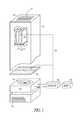
- FIG. 1is a simplified perspective view of an electronics enclosure having filter blockage detection according to an example embodiment.
- FIG. 2is a perspective view of a filter cartridge having an integrated airflow sensor according to an example embodiment.
- FIG. 3is a flow chart illustrating a process for detecting a blocked filter in an airflow path according to an example embodiment.
- FIG. 4is a block diagram of a controller according to an example embodiment.
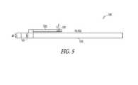
- FIG. 5is a cross section view of a filter cartridge having a differential pressure sensor for measuring a difference in pressure across the filter according to an example embodiment.
- the functions or algorithms described hereinare implemented in software or a combination of software and human implemented procedures in one embodiment.
- the softwaremay consist of computer executable instructions stored on computer readable media such as memory or other type of storage devices.
- computer readable mediais also used to represent any means by which the computer readable instructions may be received by the computer, such as by different forms of wireless transmissions.
- moduleswhich are software, hardware, firmware or any combination thereof. Multiple functions are performed in one or more modules as desired, and the embodiments described are merely examples.
- the softwareis executed on a digital signal processor, ASIC, microprocessor, or other type of processor operating on a computer system, such as a personal computer, server or other computer system.
- FIG. 1is a simplified perspective view of an electronics enclosure 100 having filter blockage detection according to an example embodiment.
- the electronics enclosure 100has multiple devices which generate heat, such as circuit cards 110 , 112 and 114 .
- at least one of the circuit cards, such as card 112has an active airflow sensor 120 disposed thereon with suitable connection 124 to a controller 130 .
- the airflow sensor 120is a pulsed thermistor, that may be fairly small and easily implementable on a circuit board or card.
- the airflow sensor 120may be positioned proximate circuitry on the circuit card that is most sensitive to heat, or otherwise positioned as desired to measure airflow across the circuit card.
- the sensormay be integrated directly on the card, and formed during manufacture of the card with other circuitry on the card.
- Airflow sensor 120is said to be active in that it uses energy in order to sense airflow.
- a pulsed thermistor(or other temperature dependent resistive device) is heated and the cooling of the thermistor is measured to determine airflow.
- Such thermistorsmay be very small, and easily implemented on circuit cards at one or more desired locations.
- Airflowis provided by a fan 135 in one embodiment, which may be a variable speed fan.
- Fan 135is coupled to controller 130 in one embodiment to control the speed of the fan to increase airflow and correspondingly decrease temperature of the circuit cards.
- a filter 140may also be provided in an airflow path that begins at openings 142 in enclosure 100 , traveling through the fan 135 , filter 140 , past the circuit cards 110 , 112 , 114 and other heat producing components as desired, exiting the enclosure 100 at openings 144 .
- Controller 130in one embodiment, monitors the airflow, and detects when airflow has changed and is indicative of a filter that is becoming or is blocked.
- the term blocked as used hereinmeans that the filter has become clogged with particulate matter, and the resistance it provides to airflow has increased. While still allowing air to flow through it, the airflow may not be adequate to sufficiently cool the components in the enclosure 100 . This may be determined by the airflow rate reaching or passing a predetermined threshold, or by more complex algorithms. It may also be a function of air temperature in various embodiments. For instance, a lower air temperature may result in less flow being needed to adequate cool the components.
- the controllerdetermines that the airflow is insufficient, it generates a signal to an output device 150 , which may sound an audible alarm or provide some visual alarm or indication of the need to replace the filter.
- the alarmmay be in the form of a message or blinking icon in various embodiments that are designed to call an operator's attention to the need for filter replacement.
- an airflow sensormay be combined or integrated into the filter 140 as illustrated in perspective view in FIG. 2 .
- the filter 140which may be a common filter material optionally encased in frame, has a tube 210 disposed through it that allows air to flow.
- the tubemay be positioned anywhere through the filter material or adjacent to it, such as through a frame, but is positioned such that airflow through the tube 210 is representative of airflow through the filter 140 .
- the tube 210is very small in diameter, such as approximately 1 mm in diameter, such that very little air bypasses the filter material and air quality within enclosure 100 is not significantly adversely affected.
- the shape of the tubemay be varied from circular to other shapes, such as rectangular or other shape.
- the tubesimply comprises an opening through the filter.
- the filter materialmay be fused to provide a wall that forms the tube, or any type of opening designed to stand up to environmental conditions and maintain its shape may be used.
- An airflow sensor 215is positioned proximate the tube, such as at or near either end, or within the tube, to provide an airflow indication representative of airflow through the tube.
- the airflow sensoris a thermistor type airflow sensor, where an element is heated, and cooling of the element is representative of the flow of fluid such as air, past the element.
- thermistorare commercially available, and may be made small enough to fit within fairly small tubes.
- Power to the thermistor, as well as signals from the thermistormay be provided by line 220 , which may be one or more conductive lines to provide current to heat the thermistor, as well as carry signals from the thermistor back to the controller 130 for analysis.
- the thermistormay be battery powered, or powered by some other means 225 , such as solar or by the airflow it is designed to measure. Small turbines may be used to power the sensor in further embodiments.
- the sensormay also have wireless capabilities for transmitting sensed airflow information.
- other types of sensorsmay be used to measure flow through the tube, such as non-active types of sensors, including turbines or other mechanically based sensors that rotate or bend (piezoelectric type) in response to airflow.
- the airflow through the filteris inversely proportional to the amount of blockage accumulated on the filter.
- the flow through the sensoris a linear function of pressure across the filter which is proportional to blockage. In other words, as the filter becomes more clogged, it allows less air to flow through it, building up pressure upstream of the filter. This increase in pressure results in an increase in the airflow through the tube, which is detected by the sensor 210 .
- the controller 130receives signals from the sensor 210 indicating the airflow levels, and may compare such levels to predetermined thresholds to determine whether or not the filter is blocked and should be replaced. In further embodiments, various algorithms in the controller may be used to track the rates at which a filter is becoming blocked, and provide predictions of when the filter should be replaced.
- the pressure developed across the filterdepends on filter blockage and the speed of the fan that is generating airflow. If the fan speed is kept constant, the pressure across the filter directly represents its blockage. In an application where the fan speed is variable, the fan speed information may be used to normalize the pressure reading to determine filter blockage. In further embodiments, other algorithms, such as a table indexed by fan speed and pressure reading, may be used to determine filter blockage.
- the airflowis inversely proportional to the amount of blockage of the filter. In other words, as the filter becomes more blocked with dust or other particles, the airflow through it, and thus past the sensor 120 decreases. If the fan speed is kept constant, the airflow reading directly represents the blockage level. If the fan speed is variable an additional compensation for fan speed is used in the controller 130 .
- the controller 130may again use a threshold to determine when the filter should be replaced. Historical temperature and or airflow data may be used to establish the threshold.
- the airflowcan be associated with circuit card temperatures to more effectively estimate when the temperature of a circuit will exceed safe operating levels.
- Airflowis a leading indicator of such temperature excursions, and therefore may provide more advanced warnings of the need for replacement. Such advanced warnings may help ensure the ability to replace filters efficiently, and further allow for graceful shut down of electronics if the filter is not replaced prior to potentially damaging heat buildup.
- FIG. 3is a flow chart illustrating a process for detecting a blocked filter in an airflow path according to an example embodiment.
- Airflowis detected at 310 from either sensor 210 or one or more sensors 120 . In some embodiments both types of sensors may be used.
- the detected airflow or airflowsis compared to one or more thresholds. If a threshold is exceeded or passed at 330 , a signal indicating blockage of the filter, or indicating that the filter needs to be replaced is provided at 330 .
- These different indicationsmay each have an associated threshold, such that the system first provides a filter replacement indication, then as the second threshold is passed, a shut down of electronics may be initiated at 340 .
- the second thresholdmay be set at a level that provides sufficient time to allow a graceful shutdown of the electronics.
- a graceful shutdownallows the electronics to save current information and status to allow the electronics to be turned back on without loss of data, and such that they may be turned back on in the same state they were in prior to shutdown.
- FIG. 4is a block diagram of a controller that may execute programming 425 for performing the above algorithms.
- a general computing device in the form of a computer 410may include a processing unit 402 , memory 404 , removable storage 412 , and non-removable storage 414 .
- Memory 404may include volatile memory 406 and non-volatile memory 408 .
- Computer 410may include—or have access to a computing environment that includes—a variety of computer-readable media, such as volatile memory 406 and non-volatile memory 408 , removable storage 412 and non-removable storage 414 .
- Computer storageincludes random access memory (RAM), read only memory (ROM), erasable programmable read-only memory (EPROM) & electrically erasable programmable read-only memory (EEPROM), flash memory or other memory technologies, compact disc read-only memory (CD ROM), Digital Versatile Disks (DVD) or other optical disk storage, magnetic cassettes, magnetic tape, magnetic disk storage or other magnetic storage devices, or any other medium capable of storing computer-readable instructions.
- Computer 410may include or have access to a computing environment that includes input 416 , output 418 , and a communication connection 420 .
- the computermay operate in a networked environment using a communication connection to connect to one or more remote computers.
- the remote computermay include a personal computer (PC), server, router, network PC, a peer device or other common network node, or the like.
- the communication connectionmay include a Local Area Network (LAN), a Wide Area Network (WAN) or other wired or wireless networks.
- LANLocal Area Network
- WAN
- Computer-readable instructions stored on a computer-readable mediumare executable by the processing unit 402 of the computer 410 .
- a hard drive, CD-ROM, and RAMare some examples of articles including a computer-readable medium.
- a filter 510has a pressure sensor 515 associated with it to measure a difference in pressure across the filter 510 .
- differential pressure sensorsmay be used, such as capacitive type pressure sensors with the difference in pressure applied across a diaphragm that bends in response to the pressure difference.
- pressure sensor 515is simply an airflow sensor and tube combination for measuring airflow through the tube. As indicated above, the airflow through the tube is a function of the pressure difference across the filter.
- Information from the pressure sensorsuch as a differential pressure sensor is combined with information from an airflow sensor 520 in the airflow path. Airflow sensor 520 and pressure sensor 515 may be formed with or integrated with the filter and/or filter frame as a package.
- an arm 525is attached to the filter, and positions the airflow sensor in a path of air flowing through the filter.
- Arm 525may be attached to the tube of the pressure sensor 515 , optionally forming a single integrated piece that may be supported by the tube through the filter.
- Airflow sensor 520may optionally be located proximate the electronics to be cooled.
- Both sensorsprovide information to the controller to generate a signal indicative of filter blockage.
- This filter blockage signalmay be derived from the pressure differential and airflow indication without regard to the fan speed.
- the ratio of pressure to airflowrepresents the filter blockage (Ohm's law).
- the combination of pressure and airflow sensorsmay be provided in an assembly, and can read filter blockage independent of fans speed or system resistance. It may also be used to detect a damaged filter, such as one that is ripped or torn, or otherwise allows significant airflow around the filter material. In such cases, the resistance will be below a selected threshold.
- the controllermay be integrated or otherwise attached to the filter, providing a single replaceable unit.
- a battery or other source of power for the controller and sensors, such as a connector for external powermay be included with the filter.
- the controllermay include a light, such as an LED or other type of display device that is controlled by the controller to indicate that the filter is blocked or becoming blocked and should be replaced.
- the controllermay be supported by the tube of sensor 515 . In further embodiments, it may be supported by the arm 525 .
- the controlleris electrically coupled to one or more of the sensors as desired. The same structure as shown in FIG. 5 may be used with one or both of the sensors.
- just using sensor 520with the tube of sensor 515 closed off or even left open, allows one to measure airflow through the filter. This is useful at least in embodiments with a single fan speed, or if multiple fan speeds, providing a fan speed indication to the controller. Similarly, just sensor 515 may be used to determine the difference in pressure across the filter. These embodiments provide a self contained filter assembly that is easily replaced.
Landscapes
- Engineering & Computer Science (AREA)
- Physics & Mathematics (AREA)
- Microelectronics & Electronic Packaging (AREA)
- General Physics & Mathematics (AREA)
- Computer Hardware Design (AREA)
- Power Engineering (AREA)
- Condensed Matter Physics & Semiconductors (AREA)
- Thermal Sciences (AREA)
- General Engineering & Computer Science (AREA)
- Aviation & Aerospace Engineering (AREA)
- Fluid Mechanics (AREA)
- Cooling Or The Like Of Electrical Apparatus (AREA)
- Filtering Of Dispersed Particles In Gases (AREA)
Abstract
Description
Claims (19)
Priority Applications (1)
| Application Number | Priority Date | Filing Date | Title |
|---|---|---|---|
| US11/458,630US7726186B2 (en) | 2006-07-19 | 2006-07-19 | Airflow sensor for filter blockage detection |
Applications Claiming Priority (1)
| Application Number | Priority Date | Filing Date | Title |
|---|---|---|---|
| US11/458,630US7726186B2 (en) | 2006-07-19 | 2006-07-19 | Airflow sensor for filter blockage detection |
Publications (2)
| Publication Number | Publication Date |
|---|---|
| US20080198896A1 US20080198896A1 (en) | 2008-08-21 |
| US7726186B2true US7726186B2 (en) | 2010-06-01 |
Family
ID=39706620
Family Applications (1)
| Application Number | Title | Priority Date | Filing Date |
|---|---|---|---|
| US11/458,630Expired - Fee RelatedUS7726186B2 (en) | 2006-07-19 | 2006-07-19 | Airflow sensor for filter blockage detection |
Country Status (1)
| Country | Link |
|---|---|
| US (1) | US7726186B2 (en) |
Cited By (16)
| Publication number | Priority date | Publication date | Assignee | Title |
|---|---|---|---|---|
| US20110086589A1 (en)* | 2009-10-14 | 2011-04-14 | Alan James Skrepcinski | Outdoor communication cabinet including fan tray and filter and method of detecting blockage of communication cabinet filter |
| US20120100794A1 (en)* | 2009-03-13 | 2012-04-26 | 4Energy Limited | Equipment enclosure |
| US20120182687A1 (en)* | 2011-01-14 | 2012-07-19 | Microsoft Corporation | Adaptive thermal management for devices |
| US20150314152A1 (en)* | 2014-05-05 | 2015-11-05 | Dresser Wayne Ab | Purge and Pressurization System with Feedback Control |
| US9183723B2 (en) | 2012-01-31 | 2015-11-10 | Cleanalert, Llc | Filter clog detection and notification system |
| US9186609B2 (en) | 2012-01-31 | 2015-11-17 | Cleanalert, Llc | Filter clog sensing system and method for compensating in response to blower speed changes |
| US20150351288A1 (en)* | 2014-05-29 | 2015-12-03 | Fujitsu Limited | Electronic apparatus and filter device |
| US9494335B1 (en)* | 2013-05-09 | 2016-11-15 | Pathian Incorporated | Building pressure control |
| US20170292719A1 (en)* | 2014-09-15 | 2017-10-12 | Samsung Electronics Co., Ltd. | Full front blowing type air conditioner |
| US9999160B1 (en)* | 2014-03-31 | 2018-06-12 | Emc Corporation | Method and system for air contamination analysis for free air cooled data centers |
| US20190083917A1 (en)* | 2017-09-18 | 2019-03-21 | Alea Labs, Inc. | Smart air filter apparatus and system |
| WO2020167839A1 (en)* | 2019-02-11 | 2020-08-20 | Broan-Nutone Llc | Systems and methods for verifying the performance of installed air ventilation systems |
| US10967321B2 (en) | 2017-11-05 | 2021-04-06 | Shashidhar Prabhakar | Air filter clog detector |
| US11781774B2 (en) | 2013-05-09 | 2023-10-10 | Pathian Incorporated | Building pressure control |
| US20250032969A1 (en)* | 2023-07-26 | 2025-01-30 | Carl Freudenberg Kg | Air filter with integrated pressure sensor |
| US12435732B1 (en) | 2024-09-19 | 2025-10-07 | Microsoft Technology Licensing, Llc | Centrifugal blower housing |
Families Citing this family (25)
| Publication number | Priority date | Publication date | Assignee | Title |
|---|---|---|---|---|
| US8033716B1 (en)* | 2006-08-23 | 2011-10-11 | Troy Marcus Tandy | Refrigeration temperature monitoring system and associated temperature display |
| CN101281057B (en)* | 2007-04-02 | 2011-06-22 | 鸿富锦精密工业(深圳)有限公司 | Airflow detection device |
| US7751990B2 (en)* | 2008-07-21 | 2010-07-06 | International Business Machines Corporation | Detecting a fouled air filter in a computer equipment enclosure |
| US8386275B2 (en)* | 2009-02-10 | 2013-02-26 | Timothy Chambers | Automatic pill dispensing device and method of use thereof |
| NL2002633C2 (en)* | 2009-03-17 | 2010-09-20 | Uptime Products B V | METHOD AND APPARATUS FOR DETERMINING THE COLD AIR BALANCE IN A CONDITIONED SPACE WITH ICT EQUIPMENT. |
| TWI360739B (en)* | 2009-05-25 | 2012-03-21 | Wistron Corp | Pressure sensing device for electronic device and |
| WO2011025988A2 (en)* | 2009-08-28 | 2011-03-03 | Raytheon Company | Architecture for gas cooled parallel microchannel array cooler |
| US20110301747A1 (en)* | 2010-02-10 | 2011-12-08 | Timothy Chambers | Automatic Pill Dispensing Device and Method of Use Thereof |
| US20120241140A1 (en)* | 2011-03-25 | 2012-09-27 | Macdonald Mark | Apparatus, system and method for airflow monitoring and thermal management in a computing device |
| US9101871B2 (en)* | 2012-04-20 | 2015-08-11 | International Business Machines Corporation | Filter systems |
| US9517429B2 (en) | 2012-11-13 | 2016-12-13 | Complete Filter Management Llc | Filtration monitoring system |
| GB201503880D0 (en)* | 2015-03-06 | 2015-04-22 | Beacon Internat Ltd | Negative pressure units |
| JP7048183B2 (en)* | 2016-08-08 | 2022-04-05 | スリーエム イノベイティブ プロパティズ カンパニー | Air filter status detection |
| US11735304B2 (en) | 2017-09-26 | 2023-08-22 | Mckesson Corporation | Robotic dispensary system and methods |
| US11530937B2 (en)* | 2017-10-12 | 2022-12-20 | Purdue Research Foundation | Directional probe for high temperature flows |
| US10753635B2 (en)* | 2018-05-31 | 2020-08-25 | Air Distribution Technologies Ip, Llc | Adjustable thermal dispersion air flow rate meter |
| US10827651B2 (en)* | 2018-07-26 | 2020-11-03 | Dell Products L.P. | Airflow characterization system |
| FR3087352B1 (en)* | 2018-10-19 | 2023-01-20 | Sogefi Filtration Spa | CONNECTED AIR FILTER, WITH A DETACHABLE DETECTION UNIT |
| US11676047B1 (en) | 2018-10-25 | 2023-06-13 | 3M Innovative Properties Company | Air quality data servicing |
| CN112839494B (en)* | 2021-02-22 | 2022-09-20 | 台州市菱士达电器有限公司 | An intelligent regulation cooling system and method for a frequency converter |
| US11778787B2 (en)* | 2022-01-28 | 2023-10-03 | Quanta Computer Inc. | System and method for thermal management in a computing environment |
| JP7618614B2 (en) | 2022-03-16 | 2025-01-21 | 株式会社Tmeic | Power Supplies |
| US20240023273A1 (en)* | 2022-07-13 | 2024-01-18 | Dell Products L.P. | Acoustically-sensitive filter fouling tests |
| US12346177B2 (en)* | 2022-07-13 | 2025-07-01 | Dell Products L.P. | Self-calculating filter fouling thresholds |
| CN115407020A (en)* | 2022-08-01 | 2022-11-29 | 联想(北京)有限公司 | Processing method and electronic equipment |
Citations (22)
| Publication number | Priority date | Publication date | Assignee | Title |
|---|---|---|---|---|
| US3504542A (en)* | 1967-08-21 | 1970-04-07 | Us Army | Air flowmeter |
| JPS6062518A (en)* | 1984-07-30 | 1985-04-10 | Hitachi Ltd | Air conditioner device |
| US4571996A (en)* | 1984-08-10 | 1986-02-25 | Allied Corporation | Air flow sensor |
| JPH02157495A (en) | 1988-12-09 | 1990-06-18 | Fujitsu General Ltd | How to detect abnormality in air conditioner fan motor |
| FR2701217A1 (en)* | 1993-02-09 | 1994-08-12 | Robin Roger Claude | Device for detecting fouling of an air filter |
| US5429649A (en)* | 1992-04-14 | 1995-07-04 | Robin; Roger C. | Device for the detection of the clogging of an air filter |
| US5467607A (en) | 1994-02-22 | 1995-11-21 | At&T Corp. | Air conditioning control system |
| US5668535A (en)* | 1995-12-07 | 1997-09-16 | Emerson Electric Co. | Filter condition sensor and indicator |
| US5769705A (en) | 1996-08-16 | 1998-06-23 | Alliance Peripheral Systems, Inc. | Thermostatically controlled enclosure for temperature sensitive equipment |
| US6128963A (en)* | 1998-05-28 | 2000-10-10 | Instrumentarium Corp. | Gas flow restricting and sensing device |
| US6319114B1 (en) | 1999-11-11 | 2001-11-20 | Degree Controls, Inc. | Thermal management system |
| US6507282B1 (en)* | 2000-01-14 | 2003-01-14 | The Holmes Group, Inc. | Filter monitoring system using a thermistor |
| US6539968B1 (en)* | 2000-09-20 | 2003-04-01 | Fugasity Corporation | Fluid flow controller and method of operation |
| US20040177703A1 (en)* | 2003-03-12 | 2004-09-16 | Schumacher Mark S. | Flow instrument with multisensors |
| DE202004011074U1 (en)* | 2004-01-22 | 2004-10-28 | Pfannenberg Gmbh | Air filter and ventilator for electronic equipment e.g. personal computer, detects filter blockage by measurement of pressure difference |
| US6917891B2 (en)* | 2003-02-28 | 2005-07-12 | Xerox Corporation | Systems and methods for diagnosing and predicting fluid flow systems using sensors |
| US7048383B2 (en)* | 2003-02-07 | 2006-05-23 | Belliveau Richard S | Theatrical fog particle protection system for image projection lighting devices |
| US7178410B2 (en)* | 2004-03-22 | 2007-02-20 | Cleanalert, Llc | Clogging detector for air filter |
| US7234312B2 (en)* | 2003-12-02 | 2007-06-26 | Electrolux Home Products, Inc. | Variable speed, electronically controlled, room air conditioner |
| US20070272082A1 (en)* | 2006-05-26 | 2007-11-29 | 3M Innovative Properties Company | Method and apparatus for monitoring the condition of a flexible filter |
| US20070277592A1 (en)* | 2006-05-30 | 2007-12-06 | 3M Innovative Properties Company | Filter sensor |
| US7334602B2 (en)* | 2003-06-27 | 2008-02-26 | Hyundai Calibration & Certification Technologies Co., Ltd. | Apparatus for controlling flow rate of gases used in semiconductor device by differential pressure |
- 2006
- 2006-07-19USUS11/458,630patent/US7726186B2/ennot_activeExpired - Fee Related
Patent Citations (22)
| Publication number | Priority date | Publication date | Assignee | Title |
|---|---|---|---|---|
| US3504542A (en)* | 1967-08-21 | 1970-04-07 | Us Army | Air flowmeter |
| JPS6062518A (en)* | 1984-07-30 | 1985-04-10 | Hitachi Ltd | Air conditioner device |
| US4571996A (en)* | 1984-08-10 | 1986-02-25 | Allied Corporation | Air flow sensor |
| JPH02157495A (en) | 1988-12-09 | 1990-06-18 | Fujitsu General Ltd | How to detect abnormality in air conditioner fan motor |
| US5429649A (en)* | 1992-04-14 | 1995-07-04 | Robin; Roger C. | Device for the detection of the clogging of an air filter |
| FR2701217A1 (en)* | 1993-02-09 | 1994-08-12 | Robin Roger Claude | Device for detecting fouling of an air filter |
| US5467607A (en) | 1994-02-22 | 1995-11-21 | At&T Corp. | Air conditioning control system |
| US5668535A (en)* | 1995-12-07 | 1997-09-16 | Emerson Electric Co. | Filter condition sensor and indicator |
| US5769705A (en) | 1996-08-16 | 1998-06-23 | Alliance Peripheral Systems, Inc. | Thermostatically controlled enclosure for temperature sensitive equipment |
| US6128963A (en)* | 1998-05-28 | 2000-10-10 | Instrumentarium Corp. | Gas flow restricting and sensing device |
| US6319114B1 (en) | 1999-11-11 | 2001-11-20 | Degree Controls, Inc. | Thermal management system |
| US6507282B1 (en)* | 2000-01-14 | 2003-01-14 | The Holmes Group, Inc. | Filter monitoring system using a thermistor |
| US6539968B1 (en)* | 2000-09-20 | 2003-04-01 | Fugasity Corporation | Fluid flow controller and method of operation |
| US7048383B2 (en)* | 2003-02-07 | 2006-05-23 | Belliveau Richard S | Theatrical fog particle protection system for image projection lighting devices |
| US6917891B2 (en)* | 2003-02-28 | 2005-07-12 | Xerox Corporation | Systems and methods for diagnosing and predicting fluid flow systems using sensors |
| US20040177703A1 (en)* | 2003-03-12 | 2004-09-16 | Schumacher Mark S. | Flow instrument with multisensors |
| US7334602B2 (en)* | 2003-06-27 | 2008-02-26 | Hyundai Calibration & Certification Technologies Co., Ltd. | Apparatus for controlling flow rate of gases used in semiconductor device by differential pressure |
| US7234312B2 (en)* | 2003-12-02 | 2007-06-26 | Electrolux Home Products, Inc. | Variable speed, electronically controlled, room air conditioner |
| DE202004011074U1 (en)* | 2004-01-22 | 2004-10-28 | Pfannenberg Gmbh | Air filter and ventilator for electronic equipment e.g. personal computer, detects filter blockage by measurement of pressure difference |
| US7178410B2 (en)* | 2004-03-22 | 2007-02-20 | Cleanalert, Llc | Clogging detector for air filter |
| US20070272082A1 (en)* | 2006-05-26 | 2007-11-29 | 3M Innovative Properties Company | Method and apparatus for monitoring the condition of a flexible filter |
| US20070277592A1 (en)* | 2006-05-30 | 2007-12-06 | 3M Innovative Properties Company | Filter sensor |
Cited By (20)
| Publication number | Priority date | Publication date | Assignee | Title |
|---|---|---|---|---|
| US20120100794A1 (en)* | 2009-03-13 | 2012-04-26 | 4Energy Limited | Equipment enclosure |
| US20110086589A1 (en)* | 2009-10-14 | 2011-04-14 | Alan James Skrepcinski | Outdoor communication cabinet including fan tray and filter and method of detecting blockage of communication cabinet filter |
| US20120182687A1 (en)* | 2011-01-14 | 2012-07-19 | Microsoft Corporation | Adaptive thermal management for devices |
| US8712598B2 (en)* | 2011-01-14 | 2014-04-29 | Microsoft Corporation | Adaptive flow for thermal cooling of devices |
| US9183723B2 (en) | 2012-01-31 | 2015-11-10 | Cleanalert, Llc | Filter clog detection and notification system |
| US9186609B2 (en) | 2012-01-31 | 2015-11-17 | Cleanalert, Llc | Filter clog sensing system and method for compensating in response to blower speed changes |
| US11781774B2 (en) | 2013-05-09 | 2023-10-10 | Pathian Incorporated | Building pressure control |
| US11359833B2 (en) | 2013-05-09 | 2022-06-14 | Pathian Incorporated | Building pressure control |
| US9494335B1 (en)* | 2013-05-09 | 2016-11-15 | Pathian Incorporated | Building pressure control |
| US9999160B1 (en)* | 2014-03-31 | 2018-06-12 | Emc Corporation | Method and system for air contamination analysis for free air cooled data centers |
| US10646734B2 (en)* | 2014-05-05 | 2020-05-12 | Wayne Fueling Systems Sweden Ab | Purge and pressurization system with feedback control |
| US20150314152A1 (en)* | 2014-05-05 | 2015-11-05 | Dresser Wayne Ab | Purge and Pressurization System with Feedback Control |
| US20150351288A1 (en)* | 2014-05-29 | 2015-12-03 | Fujitsu Limited | Electronic apparatus and filter device |
| US20170292719A1 (en)* | 2014-09-15 | 2017-10-12 | Samsung Electronics Co., Ltd. | Full front blowing type air conditioner |
| US20190083917A1 (en)* | 2017-09-18 | 2019-03-21 | Alea Labs, Inc. | Smart air filter apparatus and system |
| US10967321B2 (en) | 2017-11-05 | 2021-04-06 | Shashidhar Prabhakar | Air filter clog detector |
| WO2020167839A1 (en)* | 2019-02-11 | 2020-08-20 | Broan-Nutone Llc | Systems and methods for verifying the performance of installed air ventilation systems |
| US20220090810A1 (en)* | 2019-02-11 | 2022-03-24 | Broan-Nutone Llc | Systems and methods for verifying the performance of installed air ventilation systems |
| US20250032969A1 (en)* | 2023-07-26 | 2025-01-30 | Carl Freudenberg Kg | Air filter with integrated pressure sensor |
| US12435732B1 (en) | 2024-09-19 | 2025-10-07 | Microsoft Technology Licensing, Llc | Centrifugal blower housing |
Also Published As
| Publication number | Publication date |
|---|---|
| US20080198896A1 (en) | 2008-08-21 |
Similar Documents
| Publication | Publication Date | Title |
|---|---|---|
| US7726186B2 (en) | Airflow sensor for filter blockage detection | |
| US6319114B1 (en) | Thermal management system | |
| US9186609B2 (en) | Filter clog sensing system and method for compensating in response to blower speed changes | |
| US8493221B2 (en) | Filter fouling detection using comparative temperature rise analysis | |
| US10821388B2 (en) | Clip-on monitor for detecting clogged air-filters | |
| US7346468B2 (en) | Method and apparatus for detecting heat sink faults | |
| CN103931278A (en) | Method and device for detecting clogging of a filter | |
| JP5388252B2 (en) | Filter clogging detection device | |
| JP2017175023A (en) | Information processing apparatus, suction abnormality detection method, and suction abnormality detection program | |
| US10426063B2 (en) | System and method for cooling an information handling system | |
| JP2011249522A (en) | Determination device and determination method | |
| CN115439993B (en) | Adjusting temperature variation of air flow of air suction type smoke detector | |
| JP4468190B2 (en) | Filter clogging detection device and detection method | |
| US20140064321A1 (en) | Abnormality detection device | |
| JP4929736B2 (en) | Dust-proof filter clogging detection device and display device using the same | |
| CN101163931A (en) | Filter assembly | |
| US7162374B2 (en) | Device for the determination of flow parameters for a fluid and method for operating such a device | |
| CN100406855C (en) | Device for determining flow parameters and method for operating said device | |
| JP5920803B2 (en) | Electrical equipment | |
| US9651320B2 (en) | ICT equipment | |
| US11162912B2 (en) | Electronic apparatus, index calculating method, and computer program product | |
| JP3571015B2 (en) | Warning device and method of blocking ventilation holes of various devices | |
| CN101876669A (en) | Device and Flow Channel Obstruction Detection Method | |
| US20100088045A1 (en) | Flow meter and airflow measurement using an airfoil | |
| CN112461729A (en) | Ultra-clean room environment monitoring method and device, electronic equipment and storage medium |
Legal Events
| Date | Code | Title | Description |
|---|---|---|---|
| AS | Assignment | Owner name:DEGREE C, NEW HAMPSHIRE Free format text:ASSIGNMENT OF ASSIGNORS INTEREST;ASSIGNOR:NAIR, RAJESH M.;REEL/FRAME:018233/0875 Effective date:20060905 Owner name:DEGREE C,NEW HAMPSHIRE Free format text:ASSIGNMENT OF ASSIGNORS INTEREST;ASSIGNOR:NAIR, RAJESH M.;REEL/FRAME:018233/0875 Effective date:20060905 | |
| AS | Assignment | Owner name:DEGREE CONTROLS, INC., NEW HAMPSHIRE Free format text:ASSIGNMENT OF ASSIGNORS INTEREST;ASSIGNOR:NAIR, RAJESH M.;REEL/FRAME:021153/0026 Effective date:20080624 Owner name:DEGREE CONTROLS, INC.,NEW HAMPSHIRE Free format text:ASSIGNMENT OF ASSIGNORS INTEREST;ASSIGNOR:NAIR, RAJESH M.;REEL/FRAME:021153/0026 Effective date:20080624 | |
| FEPP | Fee payment procedure | Free format text:PAYOR NUMBER ASSIGNED (ORIGINAL EVENT CODE: ASPN); ENTITY STATUS OF PATENT OWNER: SMALL ENTITY | |
| CC | Certificate of correction | ||
| FPAY | Fee payment | Year of fee payment:4 | |
| AS | Assignment | Owner name:SISODIA, JAGAT S., NEW HAMPSHIRE Free format text:SECURITY INTEREST;ASSIGNOR:DEGREE CONTROLS, INC.;REEL/FRAME:041134/0368 Effective date:20170119 | |
| FEPP | Fee payment procedure | Free format text:MAINTENANCE FEE REMINDER MAILED (ORIGINAL EVENT CODE: REM.) | |
| LAPS | Lapse for failure to pay maintenance fees | Free format text:PATENT EXPIRED FOR FAILURE TO PAY MAINTENANCE FEES (ORIGINAL EVENT CODE: EXP.) | |
| STCH | Information on status: patent discontinuation | Free format text:PATENT EXPIRED DUE TO NONPAYMENT OF MAINTENANCE FEES UNDER 37 CFR 1.362 | |
| FP | Lapsed due to failure to pay maintenance fee | Effective date:20180601 |