US7726047B1 - Cleats and footwear for providing customized traction - Google Patents
Cleats and footwear for providing customized tractionDownload PDFInfo
- Publication number
- US7726047B1 US7726047B1US11/938,140US93814007AUS7726047B1US 7726047 B1US7726047 B1US 7726047B1US 93814007 AUS93814007 AUS 93814007AUS 7726047 B1US7726047 B1US 7726047B1
- Authority
- US
- United States
- Prior art keywords
- projections
- cleat
- perimeter
- ground
- projection
- Prior art date
- Legal status (The legal status is an assumption and is not a legal conclusion. Google has not performed a legal analysis and makes no representation as to the accuracy of the status listed.)
- Expired - Lifetime
Links
Images


Classifications
- A—HUMAN NECESSITIES
- A43—FOOTWEAR
- A43B—CHARACTERISTIC FEATURES OF FOOTWEAR; PARTS OF FOOTWEAR
- A43B5/00—Footwear for sporting purposes
- A43B5/001—Golf shoes
- A—HUMAN NECESSITIES
- A43—FOOTWEAR
- A43B—CHARACTERISTIC FEATURES OF FOOTWEAR; PARTS OF FOOTWEAR
- A43B1/00—Footwear characterised by the material
- A43B1/0027—Footwear characterised by the material made at least partially from a material having special colours
- A—HUMAN NECESSITIES
- A43—FOOTWEAR
- A43C—FASTENINGS OR ATTACHMENTS OF FOOTWEAR; LACES IN GENERAL
- A43C15/00—Non-skid devices or attachments
- A43C15/02—Non-skid devices or attachments attached to the sole
- A—HUMAN NECESSITIES
- A43—FOOTWEAR
- A43C—FASTENINGS OR ATTACHMENTS OF FOOTWEAR; LACES IN GENERAL
- A43C15/00—Non-skid devices or attachments
- A43C15/16—Studs or cleats for football or like boots
- A43C15/162—Studs or cleats for football or like boots characterised by the shape
- A—HUMAN NECESSITIES
- A43—FOOTWEAR
- A43C—FASTENINGS OR ATTACHMENTS OF FOOTWEAR; LACES IN GENERAL
- A43C15/00—Non-skid devices or attachments
- A43C15/16—Studs or cleats for football or like boots
- A43C15/162—Studs or cleats for football or like boots characterised by the shape
- A43C15/164—Studs or cleats for football or like boots characterised by the shape having a circular cross section
- A—HUMAN NECESSITIES
- A43—FOOTWEAR
- A43C—FASTENINGS OR ATTACHMENTS OF FOOTWEAR; LACES IN GENERAL
- A43C15/00—Non-skid devices or attachments
- A43C15/16—Studs or cleats for football or like boots
- A43C15/168—Studs or cleats for football or like boots with resilient means, e.g. shock absorbing means
Definitions
- the present inventionrelates to removable cleats for athletic shoes, in particular, removable cleats for golf shoes.
- a cleattook a simple form of a spike, usually made of metal, attached the bottom of a shoe. Because such spikes could damage non-athletic surfaces, and some athletic surfaces as well, variations have been made from the simple form.
- UK Patent Application 2,098,457 to Perksdiscloses surrounding a spike element of a cleat with soft material, to decrease damage done to surfaces.
- Other designsdo not use metal spikes but rather projections of different shapes, typically made of plastic, to lessen damage to surfaces; an example can be seen in U.S. design Pat. D432,770 to Breault et al., which shows projections of different heights.
- Another design, which provides a directional golf cleatis the CHAMP TRACTM spike made by MacNeill Engineering Company, Inc.
- a removable cleatIn a first embodiment of the invention there is provided a removable cleat.
- the removable cleathas a coupling element and a ground-engaging element.
- the ground-engaging elementhas a perimeter with a plurality of projections.
- the projectionsmay be divided into at least a first set of projections, made of a first material, and at least a second set of projections, made of a second material. Every other projection may be of the first set and interspersed with the projections of the second set.
- the projectionsmay include at least one projection extending beyond the perimeter of the ground-engaging element, and at least one projection not extending beyond the perimeter of the ground-engaging element.
- at least one of the plurality of projectionsmay project in a direction perpendicular to a plane formed by the perimeter of the ground-engaging element.
- the cleatmay be a directional cleat, with some projections not extending beyond more than half of the perimeter of the ground-engaging element. In an alternative embodiment, none of the projections extend beyond the perimeter of the ground-engaging element.
- the first set of projectionsmay be longer than the second set of projections.
- the first materialmay be softer than the second material.
- the removable cleatmay further include a third material that possesses a different characteristic from the first and second materials.
- the coupling elementmay be made of the third material.
- two of the materialsmay be characterized by a different color, to ease installation of the cleat in the proper direction.
- a removable cleathaving a coupling element and a ground-engaging element, wherein the ground-engaging element has a perimeter with a plurality of projections.
- Several projectionsmay be oriented substantially perpendicular to the ground or angled inwardly, and several projections may be angled outwardly to extend beyond the perimeter of the ground-engaging element.
- the outwardly angled projectionsdo not extend beyond more than half of the perimeter of the ground-engaging element.
- the cleatmay have one set of projections longer than another set of projections.
- One set of projectionsmay be made of a softer material than another set.
- the longer projectionsmay be made of a softer material, and the shorter projections made of a harder material.
- the two setsmay be interspersed.
- the coupling elementmay be made of a third material.
- two of the materialsmay be characterized by different colors, to ease installation of the cleat in the proper direction.
- a rotating oversized cleatfor a shoe.
- the rotating oversized cleatcomprises a coupling element, such that the cleat is removable, and a ground-engaging element.
- the ground-engaging elementhas a perimeter with a plurality of projections. Some of the projections may not extend beyond the perimeter, and the projections may be divided into at least a first set of projections made of a first material and at least a second set of projections made of a second material.
- the cleatmay further include a ratchet, such that the oversized cleat may rotate in only one direction.
- the ground-engaging elementmay further include a center portion and an outer portion, wherein the outer portion may be capable of rotation, and the center portion may remain static with respect to the shoe unless the oversized cleat is removed.
- the coupling elementmay include an attachment structure including at least three equally spaced radial coupling projections. Each coupling projection may be asymmetric with respect to an axis projecting radially outward from the center of the attachment structure through the radial center of the projection, and the radial center of the coupling projection may have a convex curved radial end. The coupling projection may thus be capable of interacting with a corresponding cleat receptacle so that less force is required to engage the cleat with the receptacle than to disengage the cleat from the receptacle.
- the outsole of a shoecomprising a rotating oversized cleat described above and at least one other removable cleat.
- the at least one other removable cleat of the outsolemay be a directional cleat.
- a removable cleatfor coupling to a shoe sole.
- the cleatincludes a coupling element and a surface-engaging element.
- the surface-engaging elementincludes a perimeter and a plurality of projections.
- the projectionsinclude at least a first set of projections, which may be made of a first material and a second set of projections, which may be made of a second material.
- the first set of projectionsis oriented in a direction that is substantially perpendicular to a plane formed by the perimeter.
- the second set of projectionsis oriented in a direction that is substantially parallel to a plane formed by the perimeter. Further, the second set of projections may be longer than the first set of projections, and the first material may be softer than the second material.
- the ground-engaging elementhas a bottom-most portion made of a first material, an intermediate portion located above the bottom-most portion and made of a second material, and a base portion located above the intermediate portion and made of the second material or a third material.
- the base-portion's materialis harder than the first material.
- the intermediate portionforms flexible cantilevered fingers.
- the bottom-most portionmay be located at the cleats' central axis, and the intermediate and base portions may be wider than the bottom-most portion.
- the base portionmay include on its bottom surface crenellations, which may be located to receive the flexible cantilevered fingers when the flexible cantilevered fingers are bent upwardly.
- FIG. 1is a perspective view of a removable cleat according to one embodiment of the current invention
- FIG. 2is a side view of the cleat shown in FIG. 1 ;
- FIG. 3is a bottom view of a cleat similar to the one shown in FIG. 1 , but which includes a logo;
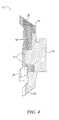
- FIG. 4is a sectional view of the cleat shown in FIG. 3 , showing a wear indicator
- FIG. 5is a bottom view of a removable cleat according to an alternative embodiment of the current invention.
- FIG. 6is a sectional view of the cleat shown in FIG. 5 across line A-A;
- FIG. 7is a sectional view of the cleat shown in FIG. 5 across line B-B;
- FIG. 8is a perspective view of a removable cleat according to an alternative embodiment of the current invention.
- FIG. 9is a bottom view of the cleat shown in FIG. 8 ;
- FIGS. 10 and 11are different side views of the cleat shown in FIG. 8 ;
- FIG. 12is a bottom view of a removable cleat according to an alternative embodiment of the current invention.
- FIGS. 13 and 14are different side views of the ground-engaging portion of the cleat shown in FIG. 12 ;
- FIG. 15is a perspective view of the cleat shown in FIG. 12 ;
- FIG. 16is a sectional view of a removable cleat according to an alternative embodiment of the current invention.
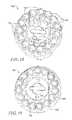
- FIGS. 17-19are perspective views of removable cleats according to alternative embodiments of the current invention.
- FIGS. 1 and 2illustrate a removable cleat 10 according to an embodiment of the current invention.
- the removable cleat 10has a coupling element 12 , which is shown in FIG. 2 , and a ground-engaging element 14 .
- the coupling element 12may be any suitable element.
- a suitable coupling elementincludes, but is not limited to, a threaded stud. This includes but is not limited to studs with conventional threading, and studs using multiple-start threads, such as shown in U.S. Pat. No. 5,974,700.
- a further example of a suitable elementis a connector such as that described in U.S. Pat. No. 6,631,571.
- the example of a suitable coupling element shown in FIG. 2is based on the MacNeill Engineering Q-lokTM System (described in, for example, U.S. Pat. No. 5,768,809, issued Jun. 23, 1998, which is incorporated herein by reference).
- the projections 18bear the weight of a user on a surface, when the removable cleat 10 is attached to an athletic shoe worn by the user, but the projections are preferably made of plastic so as to be less likely to damage the surface.
- the projections 18flex in an upward direction, away from the surface, as well as in an outward direction, away from the center of the ground-engaging element 14 .
- FIG. 3shows a version of the FIG. 1 cleat, modified to include a logo 9 on a bottom surface.
- the ground-engaging element 14includes a perimeter 16 .
- the perimeter 16may be a circumference, if the ground-engaging element is circular in shape.
- the FIG. 3 cleathas a plurality of projections 18 at the perimeter 16 .
- the plurality of projections 18may also be disposed on perimeter 16 such that the projections 18 do not extend beyond perimeter 16 .
- the plurality of projections 18may extend in a direction substantially perpendicular to a plane formed by the perimeter, i.e., substantially perpendicular to the ground.
- some projectionsmay extend beyond the perimeter and some may extend in a direction substantially perpendicular to the ground, as shown in the embodiments shown in FIGS. 5-11 , as discussed below.
- the projections 18are divided into two sets of projections, a first set 20 and a second set 22 .
- the first set 20is composed of a first material
- the second set 22is composed of a second material. Further sets may be made in this manner, such that there could be a third set of projections made of a third material, a fourth set of projections made of a fourth material, and so on. Other materials may also be added to the removable cleat 10 without including further sets of projections.
- the coupling element 12may be made of a third material that is different from the first and second materials used in the plurality of projections 18 .
- a third set of projectionscould be made of a fourth material, a fourth set of projections could be made of a fifth material, and so on.
- one of the additional sets of projectionscould be made of the same material as the coupling element.
- the first set 20 and the second set 22are preferably interspersed with each other, as shown in the figures. Further, each of these sets of projections may be of different colors.
- a single wear indicator 11is shown as the logo 9 , for example, on the removable cleat 10 in FIG. 4 , which shows a cross-section of the removable cleat 10 in FIG. 3 along axis A-A.
- the wear indicator 11may be used on many of the cleats described herein.
- the wear indicator 11is shown in FIG. 4 as being centrally located on the surface of the removable cleat 10 that includes ground-engaging element 14 .
- the wear indicator 11is a layer of softer material over a harder material; the two materials have different colors. As the removable cleat 10 is used, and the plurality of projections 18 flex, the wear indicator 11 comes into contact with surfaces, causing stress.
- the central location shown in FIG. 4is just one possible placement for the wear indicator 11 .
- a wear indicator 11may be placed at the end of each longer projection 20 , as these projections come into more contact with surfaces than shorter projections 22 .
- a wear indicator 11may also be placed at the end of each shorter projection 22 , if these are made of a less durable material than longer projections 20 . It is also possible to place a wear indicator 11 on any or every projection of a cleat, so that when any projection shows wear, the user is alerted to the potential need to replace the cleat.
- the first set of projections 20may be longer than the second set of projections 22 , and made of a material that is softer than the material of second set of projections 22 .
- the softer material that composes the first set of projections 20may be made of, for example but not limited to, a thermoplastic urethane, acetal resin, nylon, or thermoplastic rubber.
- the durometermay be in the range of 60 shore A to 90 A, and in a preferred embodiment is 90 shore A.
- Thermoplastic urethanes, acetal resins, and nylonscan also be used as the material for harder projections, such as the first set of projections 21 .
- the durometermay range from 95 shore A to S60D, with the preferred embodiment being 95 shore A. It is also possible to use one of these harder graded materials to make the coupling element 12 .
- the first set of projections 20being longer and made of a softer material, would come into contact with a surface first and bend more easily, causing less damage to the surface.
- the second set of projections 22being shorter and made of a harder material, would provide additional support and stability on surfaces.
- the flexibility of the first set of projections 20may be increased, as well. For example, as is known in the prior art, the structure and shape of the projections may increase their flexibility. Such an example is when the cross-section of the projection is made smaller or thinner.
- FIGS. 5-7show a variation of the cleat shown in FIGS. 3 and 4 , wherein three of the six projections are disposed substantially perpendicular to the shoe sole—i.e., substantially perpendicular to the ground—and wherein the remaining three projections are angled outwardly from the cleat's vertical axis.
- the substantially perpendicular projections 520 , 522are thus oriented so as to be compressed when the shoe engages the ground. Instead of projecting perpendicularly, these projections may be angled inwardly.
- the outwardly angled projections 20 , 22are oriented to deflect when the shoe engages the ground.
- one substantially perpendicular projection 520is longer and made from a softer material than the remaining two substantially perpendicular projections 522 .
- Two outwardly angled projections 20are made of the same material as the longer substantially perpendicular projection 520
- one outwardly angled projection 22is made of the same material as the shorter substantially perpendicular projections 522 ; the former material being softer than the latter material.
- the softer outwardly angled projections 20are longer than the harder outwardly angled projection 22 .
- FIGS. 5-7the softer outwardly angled projections 20 are longer than the harder outwardly angled projection 22 .
- the ends of all the projections 20 , 520 made from the softer materialare at approximately the same distance from the shoe sole, and the ends of all the projections 22 , 522 made from the harder material are at approximately the same distance from the shoe sole. It will be appreciated that the arrangement of projections shown in FIGS. 5-7 provides directional traction, and when used, for instance, with a Q-lok-type receptacle, the user can orient the direction of the cleat in one of three different directions depending on the conditions and the desires of the user.
- FIGS. 8-11show another variation of the cleat shown in FIGS. 3 and 4 , and the cleat shown in FIGS. 5-7 .
- the cleat shown in FIGS. 8-11has three substantially perpendicular projections 820 , 822 , which are oriented so as to be compressed when the shoe engages the ground, and three outwardly angled projections 20 , 22 , which are oriented to deflect when the shoe engages the ground.
- two of the softer, longer projections 820are substantially perpendicular, and only one of the shorter, harder projections 822 is substantially perpendicular.
- the various different materials that form the different groups of projections in a directional cleatmay each be a different color. Such coloring may be used to help ease correct installation of such a directional cleat.
- the outsole of the shoemay be marked with different colors in order to assist the wearer in the aligning the cleats in the preferred manner.
- FIGS. 12-15show another removable cleat according to the current invention.
- the perimeter of the removable cleat shown in FIGS. 12-15defines an unconventional shape, as compared with, for example, the perimeter of the removable cleat shown in FIG. 1 . Regardless of shape, the perimeter of the removable cleat may be said to define a plane.
- the plurality of projectionsincludes two sets of projections, with each set oriented in a different direction relative to the plane formed by the perimeter.
- a plurality of ground projections 17extend, for example, in a direction that is substantially perpendicular to the plane, i.e., substantially perpendicular to the ground.
- the plurality of ground projections 17are made of a first material.
- a plurality of side projectionsextends, for example, in a direction that is substantially parallel to the plane, i.e., substantially parallel to the ground.
- the plurality of side projections 19are made of a second material that is different from the material used to make the plurality of ground projections 17 .
- the plurality of side projections 19are longer than the plurality of ground projections 17
- the first material that composes the plurality of ground projections 17is softer than the second material that composes the plurality of side projections 19 .
- the plurality of projectionsmay include further groupings made in the manner described above, such that there could be a group of projections made of a third material and oriented in a third direction relative to the plane, a group of projections made of a fourth material oriented in a fourth direction relative to the plane, and so on. Further, it is possible for other materials to be incorporated into the removable cleat without adding other projections. For example, the coupling element of the removable cleat may be made of a third material. If a further grouping or groupings of projections were included in such a cleat, the third group of projections could be made of a fourth material, the fourth group of projection could be made of a fifth material, and so on.
- the embodiment of the removable cleat shown in FIGS. 12-15could be configured in other ways as well.
- the cleatmay include a set of angled projections that are oriented at an acute angle to the plane formed by the perimeter, i.e., at an acute angle to the ground.
- the angled set of projectionscould be made of a second material.
- the angled set of projectionscould include at least one projection that extends beyond the perimeter of the removable cleat. Alternatively, the angled projections are short enough so as to not extend beyond the perimeter of the removable cleat.
- the set of projections that are substantially parallel to the planeare longer than the angled set of projections, and the second material that composes the set of angled projections is softer than the first material that composes the set of projections that are substantially parallel to the plane.
- the plurality of projections of this embodimentcould further include other sets of projections oriented at different acute angles than the set of angled projections, with each set of projections made of a further different material. Additionally, one of the other sets of projections may be oriented in a direction substantially perpendicular to that of the plane formed by the perimeter, and made of a different material.
- FIG. 16shows a sectional view of a cleat according to an alternative embodiment of the current invention.
- the cleat depicted in FIG. 16is made of three different materials, all of which are thermoplastic in a preferred embodiment.
- the bottom-most portion 161may be made of the softest material so as to comfortably cushion impacts on hard surfaces. This soft bottom-most portion 161 may have a suction-cup shape at its bottom end so as to improve traction on certain types of surfaces.
- This soft bottom-most portion 161is preferably located at the cleat's central axis, as shown in FIG. 16 .
- Over and surrounding the bottom-most portion 116is a second material forming a set of flexible fingers 167 , radiating outwardly and tilting downwardly when no force is being applied to them.
- This second materialis harder than the bottom-most portion's material but nevertheless has sufficient flexibility to permit the fingers 167 to bend upwardly when they come into contact with the ground.
- a relatively rigid portion 169which may be disk-shaped and which is made of a third material. This third material is more rigid than the first two materials, from which the bottom-most portion 161 and the fingers 167 are made.
- both the fingers 167 and the rigid portion 169are made of the same material; in this embodiment, the fingers are thin in order to make them more flexible than the rigid portion.
- the rigid portion 169may have a downwardly protruding rim 168 on its bottom surface at its periphery. Such a rim 168 improves traction on certain types of surfaces. This rim 169 may include crenellations that further improve the traction on certain types of surfaces. These crenellations may also be lined up with the fingers 167 so that the fingers are received into the crenellations when the fingers are bent upwardly.
- the coupling element 12may also be made of the third material, or alternatively it may be made of a fourth material, such as a harder thermoplastic or a metal.
- FIGS. 17-19show various embodiments of cleats that may be used in the current invention.
- an oversized cleat 100has a coupling element and a ground-engaging element 104 .
- the oversized cleat 100has a perimeter 106 . Disposed adjacent the perimeter 106 are a plurality of projections 108 . The plurality of projections 108 do not extend beyond the perimeter 106 .
- the oversized cleat 100may also have a plurality of projections 126 that are located internally from the perimeter 106 on the surface of the ground-engaging element 104 , for example, as seen in FIG. 18 . In any of FIGS. 17-19 , the plurality of projections 108 may be grouped into two or more sets of projections.
- some of the plurality of projections 108may be part of a first set 110 , and some part of a second set 112 .
- the first set 110may be made of a first material
- the second set 112may made of a second different material.
- the projections of the first set 110may be interspersed with the projections of the second set 112 . It is possible to divide the plurality of projections 108 into any number of sets, with each set of projections made of a different material. For example, in FIG.
- the plurality of projections 108may be grouped into a first set 120 , a second set 122 , a third set 124 , and a fourth set 126 , with each set made of a different material.
- the outer projections 120 , 122 , 124have convex bottom surfaces.
- the projections 108have concave bottom surfaces.
- the oversized cleat 100may be made to rotate when attached to a shoe using, for example, a primary connector as used in the MacNeill Engineering Q-lokTM System (described in, for example, U.S. Pat. No. 5,768,809, issued Jun. 23, 1998).
- the direction of rotationmay be limited by a ratchet, such that the oversized cleat 100 is able to rotate in only one direction as determined by placement of the ratchet.
- This limited rotation directionmay be desirable. For example, during a proper golf swing, the back leg and foot of the golfer rotate in the direction of the swing, such that the back foot points in the direction of travel of the golf ball at the completion of the swing. Though the back foot and leg rotate, ideally the foot should not otherwise move.
- a shoe for the back foot containing a rotating cleat such as the oversized cleat 100would thus be advantageous.
- the ratchet of oversized cleat 100could be configured such that oversized cleat 100 could rotate to permit the wearer's foot to point in the direction of travel of the golf ball.
- the rotating oversized cleat 100would be placed on the front of the outsole of the shoe that the golfer wears on his or her back foot.
- the oversized cleat 100would thereby provide traction to help minimize any motion of the back foot other than the desired rotation motion, while easily allowing the desired rotation motion to occur. Used in this manner, the oversized cleat 100 could help improve a golfer's swing.
- a non-rotating oversized cleatmay be placed on the front of the outsole of the shoe that the golfer wears on his or her front foot.
- Conventionally sized cleats, and in a preferred embodiment directional cleats,may be located on the back of the outsoles.
- the coupling elementmay comprise conventional threading, multiple-start threads, such as shown in U.S. Pat. No. 5,974,700, or the connectors described in U.S. Pat. No. 6,631,571 or 5,768,809.
- the coupling elementmay be adaptable so that the cleat may be received into different types of receptacles.
- a simple example of such an adaptable coupling elementis one that may be accepted into a conventional metal threaded socket, or by using an adapter, may be accepted into a large-thread plastic socket.
- the adaptermay have on its inner diameter conventional threading, so that the adapter may be screwed on over the metal threads of the coupling element.
- the adapter's outer diameterwould have threads compatible with a large-thread socket.
- the cleatmay be accepted into a conventionally threaded metal socket, and with the adapter, the cleat may be accepted into a plastic large-thread socket.
- Other types of adaptersmay be used to convert different types of coupling elements to work in different types of receptacles.
Landscapes
- Health & Medical Sciences (AREA)
- General Health & Medical Sciences (AREA)
- Physical Education & Sports Medicine (AREA)
- Footwear And Its Accessory, Manufacturing Method And Apparatuses (AREA)
Abstract
Description
Claims (12)
Priority Applications (5)
| Application Number | Priority Date | Filing Date | Title |
|---|---|---|---|
| US11/938,140US7726047B1 (en) | 2004-01-26 | 2007-11-09 | Cleats and footwear for providing customized traction |
| US12/495,045US8181367B1 (en) | 2004-01-26 | 2009-06-30 | Cleats and footwear for providing customized traction |
| US13/452,001US8601725B1 (en) | 2004-01-26 | 2012-04-20 | Cleats and footwear for providing customized traction |
| US14/048,355US9066554B2 (en) | 2004-01-26 | 2013-10-08 | Cleats and footwear for providing customized traction |
| US14/634,090US9271540B1 (en) | 2004-01-26 | 2015-02-27 | Cleats and footwear for providing customized traction |
Applications Claiming Priority (4)
| Application Number | Priority Date | Filing Date | Title |
|---|---|---|---|
| US53924404P | 2004-01-26 | 2004-01-26 | |
| US55748804P | 2004-03-30 | 2004-03-30 | |
| US4369105A | 2005-01-26 | 2005-01-26 | |
| US11/938,140US7726047B1 (en) | 2004-01-26 | 2007-11-09 | Cleats and footwear for providing customized traction |
Related Parent Applications (1)
| Application Number | Title | Priority Date | Filing Date |
|---|---|---|---|
| US4369105ADivision | 2004-01-26 | 2005-01-26 |
Related Child Applications (1)
| Application Number | Title | Priority Date | Filing Date |
|---|---|---|---|
| US12/495,045DivisionUS8181367B1 (en) | 2004-01-26 | 2009-06-30 | Cleats and footwear for providing customized traction |
Publications (1)
| Publication Number | Publication Date |
|---|---|
| US7726047B1true US7726047B1 (en) | 2010-06-01 |
Family
ID=42200073
Family Applications (5)
| Application Number | Title | Priority Date | Filing Date |
|---|---|---|---|
| US11/938,140Expired - LifetimeUS7726047B1 (en) | 2004-01-26 | 2007-11-09 | Cleats and footwear for providing customized traction |
| US12/495,045Expired - Fee RelatedUS8181367B1 (en) | 2004-01-26 | 2009-06-30 | Cleats and footwear for providing customized traction |
| US13/452,001Expired - LifetimeUS8601725B1 (en) | 2004-01-26 | 2012-04-20 | Cleats and footwear for providing customized traction |
| US14/048,355Expired - LifetimeUS9066554B2 (en) | 2004-01-26 | 2013-10-08 | Cleats and footwear for providing customized traction |
| US14/634,090Expired - LifetimeUS9271540B1 (en) | 2004-01-26 | 2015-02-27 | Cleats and footwear for providing customized traction |
Family Applications After (4)
| Application Number | Title | Priority Date | Filing Date |
|---|---|---|---|
| US12/495,045Expired - Fee RelatedUS8181367B1 (en) | 2004-01-26 | 2009-06-30 | Cleats and footwear for providing customized traction |
| US13/452,001Expired - LifetimeUS8601725B1 (en) | 2004-01-26 | 2012-04-20 | Cleats and footwear for providing customized traction |
| US14/048,355Expired - LifetimeUS9066554B2 (en) | 2004-01-26 | 2013-10-08 | Cleats and footwear for providing customized traction |
| US14/634,090Expired - LifetimeUS9271540B1 (en) | 2004-01-26 | 2015-02-27 | Cleats and footwear for providing customized traction |
Country Status (1)
| Country | Link |
|---|---|
| US (5) | US7726047B1 (en) |
Cited By (13)
| Publication number | Priority date | Publication date | Assignee | Title |
|---|---|---|---|---|
| US20080196276A1 (en)* | 2007-02-16 | 2008-08-21 | Mcmullin Faris W | Multi-Traction Effect Shoe Cleat |
| US20090223088A1 (en)* | 2008-03-06 | 2009-09-10 | Softspikes, Llc | Athletic Shoe Cleat With Dynamic Traction and Method of Making and Using Same |
| US20100186261A1 (en)* | 2009-01-29 | 2010-07-29 | Nike,Inc. | Article of Footwear with Suspended Stud Assembly |
| USD631240S1 (en)* | 2009-12-30 | 2011-01-25 | Softspikes, Llc | Athletic shoe cleat |
| US20110191204A1 (en)* | 2001-08-09 | 2011-08-04 | Acushnet Company | Computerized article customization system and method for use thereof |
| US20130326908A1 (en)* | 2012-06-11 | 2013-12-12 | Taylor Made Golf Company, Inc. | Golf shoe outsole |
| US20140215862A1 (en)* | 2013-02-05 | 2014-08-07 | Nike, Inc. | Cleats, cleated sole structures, molds, and molding methods for in-molding articles |
| WO2014123952A1 (en)* | 2013-02-05 | 2014-08-14 | Nike, Inc. | Cleats, cleated sole structures, molds, and molding methods for in-molding articles |
| US20160044995A1 (en)* | 2014-08-14 | 2016-02-18 | Teng-Jen Yang | Method for integrally forming a sole with hobnails |
| TWI576058B (en)* | 2015-07-24 | 2017-04-01 | 楊登任 | Method for manufacturing a shoe sole with multi-material golf shoes nails |
| US9609919B2 (en) | 2012-12-18 | 2017-04-04 | Pride Manufacturing Company, Llc | Traction cleat and receptacle |
| USD796228S1 (en)* | 2016-06-23 | 2017-09-05 | Custom Accessories, Inc. | Floor mat retaining cleat |
| US11540595B2 (en)* | 2016-05-17 | 2023-01-03 | Under Armour, Inc. | Athletic cleat |
Families Citing this family (4)
| Publication number | Priority date | Publication date | Assignee | Title |
|---|---|---|---|---|
| US7726047B1 (en)* | 2004-01-26 | 2010-06-01 | Cleats Llc | Cleats and footwear for providing customized traction |
| US8806779B2 (en) | 2011-09-16 | 2014-08-19 | Nike, Inc. | Shaped support features for footwear ground-engaging members |
| EP3297478B1 (en)* | 2015-05-22 | 2021-11-10 | Nike Innovate C.V. | Ground-engaging structures for articles of footwear |
| US20170238649A1 (en)* | 2016-02-22 | 2017-08-24 | Ariat International, Inc. | Articles of footwear with localized traction regions |
Citations (25)
| Publication number | Priority date | Publication date | Assignee | Title |
|---|---|---|---|---|
| DE3811513A1 (en) | 1988-04-06 | 1989-10-19 | Konrad Ed Matulla | Football boot screw-stud of flexible deformation, on the base of which two or more studs/bosses are mounted and, thereon, "mud deflectors" in functional association |
| FR2679421A1 (en) | 1991-07-24 | 1993-01-29 | Bouyer Jean Louis | CRAMPON FOR SPORTS SHOE. |
| US5259129A (en) | 1992-04-24 | 1993-11-09 | Warm Springs Golf Club, Inc. | Winter golf shoe spikes |
| USD371895S (en) | 1994-08-31 | 1996-07-23 | Mcmullin Faris W | Triangle ridge golf shoe spike |
| US5794367A (en) | 1997-02-20 | 1998-08-18 | Greenkeepers, Inc. | Sports shoe cleats |
| US5887371A (en) | 1997-02-18 | 1999-03-30 | Curley, Jr.; John J. | Footwear cleat |
| US5996260A (en) | 1998-10-26 | 1999-12-07 | Macneill Engineering Company, Inc. | Dual density plastic cleat for footwear |
| US6023860A (en) | 1997-12-11 | 2000-02-15 | Softspikes, Inc. | Athletic shoe cleat |
| US6041526A (en) | 1997-03-11 | 2000-03-28 | Trisport Limited | Ground-gripping elements for shoe soles |
| US6052923A (en) | 1996-12-20 | 2000-04-25 | Softspikes, Inc. | Golf cleat |
| USD432770S (en) | 1999-06-21 | 2000-10-31 | Macneill Engineering Company, Inc. | Non-penetrating golf cleat |
| US6138386A (en) | 1997-09-03 | 2000-10-31 | Spalding Sports Worldwide, Inc. | Composite cleat for athletic shoe |
| US20010011429A1 (en)* | 1999-12-20 | 2001-08-09 | Peabody Steven R. | Wear-indicating exchangeable golf cleat |
| USD449431S1 (en)* | 2000-08-14 | 2001-10-23 | Macneill Engineering Company, Inc. | Cleat for footwear |
| US20030033735A1 (en)* | 2001-08-20 | 2003-02-20 | Yasuhiro Ijiri | Friction device for footwear |
| USD473699S1 (en)* | 2000-08-23 | 2003-04-29 | Macneill Engineering Company, Inc. | Cleat for footwear |
| US20030131502A1 (en) | 2000-01-24 | 2003-07-17 | Yasuyuki Terashima | Golf Shoe Cleat |
| US20040040182A1 (en)* | 2002-08-27 | 2004-03-04 | Mcmullin Faris W. | Indexable shoe cleat with improved traction |
| US6823613B2 (en) | 2000-11-14 | 2004-11-30 | Trisport Limited | Studded footwear |
| US6834445B2 (en) | 2002-07-16 | 2004-12-28 | Softspikes, Llc | Shoe cleat with improved traction |
| US6904707B2 (en) | 2003-07-01 | 2005-06-14 | Softspikes, Llc | Indexable shoe cleat with improved traction |
| USD509050S1 (en) | 2003-06-30 | 2005-09-06 | Macneill Engineering Company, Inc. | Dual durometer cleat |
| US7040043B2 (en) | 2003-08-11 | 2006-05-09 | Softspikes, Llc | Shoe cleat |
| US7047674B1 (en) | 1999-05-31 | 2006-05-23 | Bruce Henry Garvie | Cleat for footwear |
| US7073281B2 (en) | 2001-06-28 | 2006-07-11 | Japana Co., Ltd. | Spike for golf shoes |
Family Cites Families (13)
| Publication number | Priority date | Publication date | Assignee | Title |
|---|---|---|---|---|
| US3512275A (en) | 1968-04-01 | 1970-05-19 | John L Leavitt | Non-penetrating cleat arrangement |
| US3656245A (en) | 1970-09-08 | 1972-04-18 | Henry H Wilson | Athletic shoe cleat |
| DE2540426A1 (en) | 1975-09-11 | 1977-03-17 | Berthold Kaestle | Sports shoe grip element - has spiked plate fixed to screw piece, and is used on plastics running tracks |
| US4014114A (en) | 1975-11-28 | 1977-03-29 | Three Line Research & Development Co., Inc. | Spike cluster |
| US5860228A (en)* | 1997-05-12 | 1999-01-19 | Bite, Llc | All purpose nubbed cleat for shoes and other non-slip applications |
| US6338208B1 (en)* | 1997-05-28 | 2002-01-15 | Concurrent Technologies Corporation | Short shoe spike |
| USD439733S1 (en)* | 2000-01-31 | 2001-04-03 | Macneill Engineering Company, Inc. | Removable tread device for footwear |
| USD452062S1 (en)* | 2000-06-28 | 2001-12-18 | Macneill Engineering Company, Inc. | Removable tread device for footwear |
| USD452063S1 (en)* | 2000-06-28 | 2001-12-18 | Macneill Engineering Company, Inc. | Removable tread device for footwear |
| JP2002315605A (en)* | 2001-04-19 | 2002-10-29 | Minebea Co Ltd | Stud and shoe with stud |
| US7726047B1 (en)* | 2004-01-26 | 2010-06-01 | Cleats Llc | Cleats and footwear for providing customized traction |
| US20080271346A1 (en)* | 2007-05-03 | 2008-11-06 | Farmer Paul J | Platform cleat |
| EP2247208A4 (en)* | 2008-02-26 | 2013-10-02 | Softspikes Llc | Improved traction cleat for field sports |
- 2007
- 2007-11-09USUS11/938,140patent/US7726047B1/ennot_activeExpired - Lifetime
- 2009
- 2009-06-30USUS12/495,045patent/US8181367B1/ennot_activeExpired - Fee Related
- 2012
- 2012-04-20USUS13/452,001patent/US8601725B1/ennot_activeExpired - Lifetime
- 2013
- 2013-10-08USUS14/048,355patent/US9066554B2/ennot_activeExpired - Lifetime
- 2015
- 2015-02-27USUS14/634,090patent/US9271540B1/ennot_activeExpired - Lifetime
Patent Citations (37)
| Publication number | Priority date | Publication date | Assignee | Title |
|---|---|---|---|---|
| DE3811513A1 (en) | 1988-04-06 | 1989-10-19 | Konrad Ed Matulla | Football boot screw-stud of flexible deformation, on the base of which two or more studs/bosses are mounted and, thereon, "mud deflectors" in functional association |
| FR2679421A1 (en) | 1991-07-24 | 1993-01-29 | Bouyer Jean Louis | CRAMPON FOR SPORTS SHOE. |
| US5259129A (en) | 1992-04-24 | 1993-11-09 | Warm Springs Golf Club, Inc. | Winter golf shoe spikes |
| US6327797B1 (en) | 1992-04-24 | 2001-12-11 | Softspikes, Inc. | Golf shoe spikes |
| US6009640A (en) | 1992-04-24 | 2000-01-04 | Softspikes, Inc. | Golf shoe spikes |
| US6354021B1 (en) | 1992-04-24 | 2002-03-12 | Softspikes, Inc. | Winter golf shoe spikes |
| USD371895S (en) | 1994-08-31 | 1996-07-23 | Mcmullin Faris W | Triangle ridge golf shoe spike |
| US6052923A (en) | 1996-12-20 | 2000-04-25 | Softspikes, Inc. | Golf cleat |
| US6094843A (en) | 1997-02-18 | 2000-08-01 | Softspikes, Inc. | Footwear cleat |
| US5887371A (en) | 1997-02-18 | 1999-03-30 | Curley, Jr.; John J. | Footwear cleat |
| US6209230B1 (en) | 1997-02-18 | 2001-04-03 | John J. Curley, Jr. | Footwear cleat |
| US5794367A (en) | 1997-02-20 | 1998-08-18 | Greenkeepers, Inc. | Sports shoe cleats |
| US6530162B1 (en) | 1997-02-20 | 2003-03-11 | Green Keepers, Inc. | Sports shoe cleats |
| US6041526A (en) | 1997-03-11 | 2000-03-28 | Trisport Limited | Ground-gripping elements for shoe soles |
| US6138386A (en) | 1997-09-03 | 2000-10-31 | Spalding Sports Worldwide, Inc. | Composite cleat for athletic shoe |
| US6167641B1 (en) | 1997-12-11 | 2001-01-02 | Softspikes, Inc. | Athletic shoe cleat |
| US6023860A (en) | 1997-12-11 | 2000-02-15 | Softspikes, Inc. | Athletic shoe cleat |
| US6305104B1 (en) | 1997-12-11 | 2001-10-23 | Mcmullin Faris W. | Athletic shoe cleat |
| US5996260A (en) | 1998-10-26 | 1999-12-07 | Macneill Engineering Company, Inc. | Dual density plastic cleat for footwear |
| US7047674B1 (en) | 1999-05-31 | 2006-05-23 | Bruce Henry Garvie | Cleat for footwear |
| USD432770S (en) | 1999-06-21 | 2000-10-31 | Macneill Engineering Company, Inc. | Non-penetrating golf cleat |
| US20010011429A1 (en)* | 1999-12-20 | 2001-08-09 | Peabody Steven R. | Wear-indicating exchangeable golf cleat |
| US7073280B2 (en) | 2000-01-24 | 2006-07-11 | Japana Co., Ltd. | Cleat for golf shoes |
| US6675505B2 (en) | 2000-01-24 | 2004-01-13 | Japana Co., Ltd. | Golf shoe cleat |
| US20030131502A1 (en) | 2000-01-24 | 2003-07-17 | Yasuyuki Terashima | Golf Shoe Cleat |
| US20030172556A1 (en) | 2000-01-24 | 2003-09-18 | Yasuyuki Terashima | Cleat for golf shoes |
| USD449431S1 (en)* | 2000-08-14 | 2001-10-23 | Macneill Engineering Company, Inc. | Cleat for footwear |
| USD473699S1 (en)* | 2000-08-23 | 2003-04-29 | Macneill Engineering Company, Inc. | Cleat for footwear |
| US6823613B2 (en) | 2000-11-14 | 2004-11-30 | Trisport Limited | Studded footwear |
| US7073281B2 (en) | 2001-06-28 | 2006-07-11 | Japana Co., Ltd. | Spike for golf shoes |
| US20030033735A1 (en)* | 2001-08-20 | 2003-02-20 | Yasuhiro Ijiri | Friction device for footwear |
| US6834445B2 (en) | 2002-07-16 | 2004-12-28 | Softspikes, Llc | Shoe cleat with improved traction |
| US20040040182A1 (en)* | 2002-08-27 | 2004-03-04 | Mcmullin Faris W. | Indexable shoe cleat with improved traction |
| US6834446B2 (en) | 2002-08-27 | 2004-12-28 | Softspikes, Llc | Indexable shoe cleat with improved traction |
| USD509050S1 (en) | 2003-06-30 | 2005-09-06 | Macneill Engineering Company, Inc. | Dual durometer cleat |
| US6904707B2 (en) | 2003-07-01 | 2005-06-14 | Softspikes, Llc | Indexable shoe cleat with improved traction |
| US7040043B2 (en) | 2003-08-11 | 2006-05-09 | Softspikes, Llc | Shoe cleat |
Cited By (25)
| Publication number | Priority date | Publication date | Assignee | Title |
|---|---|---|---|---|
| US20110191204A1 (en)* | 2001-08-09 | 2011-08-04 | Acushnet Company | Computerized article customization system and method for use thereof |
| US8020322B2 (en)* | 2007-02-16 | 2011-09-20 | Pride Manufacturing Company, Llc | Multi-traction effect shoe cleat |
| US20080196276A1 (en)* | 2007-02-16 | 2008-08-21 | Mcmullin Faris W | Multi-Traction Effect Shoe Cleat |
| US20090223088A1 (en)* | 2008-03-06 | 2009-09-10 | Softspikes, Llc | Athletic Shoe Cleat With Dynamic Traction and Method of Making and Using Same |
| US8245422B2 (en)* | 2008-03-06 | 2012-08-21 | Softspikes, Llc | Athletic shoe cleat with dynamic traction and method of making and using same |
| US9101180B2 (en) | 2009-01-29 | 2015-08-11 | Nike, Inc. | Article of footwear with suspended stud assembly |
| US20100186261A1 (en)* | 2009-01-29 | 2010-07-29 | Nike,Inc. | Article of Footwear with Suspended Stud Assembly |
| US8220185B2 (en)* | 2009-01-29 | 2012-07-17 | Nike, Inc. | Article of footwear with suspended stud assembly |
| US8819965B2 (en) | 2009-01-29 | 2014-09-02 | Nike, Inc. | Article of footwear with suspended stud assembly |
| USD631240S1 (en)* | 2009-12-30 | 2011-01-25 | Softspikes, Llc | Athletic shoe cleat |
| US20130326908A1 (en)* | 2012-06-11 | 2013-12-12 | Taylor Made Golf Company, Inc. | Golf shoe outsole |
| US9609919B2 (en) | 2012-12-18 | 2017-04-04 | Pride Manufacturing Company, Llc | Traction cleat and receptacle |
| CN105246363A (en)* | 2013-02-05 | 2016-01-13 | 耐克创新有限合伙公司 | Cleats, cleated sole structures, molds, and molding methods for in-molding articles |
| US9125452B2 (en)* | 2013-02-05 | 2015-09-08 | Nike, Incorporated | Cleats, cleated sole structures, molds, and molding methods for in-molding articles |
| WO2014123952A1 (en)* | 2013-02-05 | 2014-08-14 | Nike, Inc. | Cleats, cleated sole structures, molds, and molding methods for in-molding articles |
| JP2016506883A (en)* | 2013-02-05 | 2016-03-07 | ナイキ イノベイト セー. フェー. | Cleat, sole structure with cleat, mold for in-mold molding of product, and molding method |
| AU2014215438B2 (en)* | 2013-02-05 | 2017-01-05 | Nike Innovate C.V. | Cleats, cleated sole structures, molds, and molding methods for in-molding articles |
| US20140215862A1 (en)* | 2013-02-05 | 2014-08-07 | Nike, Inc. | Cleats, cleated sole structures, molds, and molding methods for in-molding articles |
| CN106723664A (en)* | 2013-02-05 | 2017-05-31 | 耐克创新有限合伙公司 | Wedge, the footwear sole construction for having wedge, mould and the method for moulding for interior molded articles |
| US20160044995A1 (en)* | 2014-08-14 | 2016-02-18 | Teng-Jen Yang | Method for integrally forming a sole with hobnails |
| US9750299B2 (en)* | 2014-08-14 | 2017-09-05 | Teng-Jen Yang | Method for integrally forming a sole with hobnails |
| TWI576058B (en)* | 2015-07-24 | 2017-04-01 | 楊登任 | Method for manufacturing a shoe sole with multi-material golf shoes nails |
| US11540595B2 (en)* | 2016-05-17 | 2023-01-03 | Under Armour, Inc. | Athletic cleat |
| US12256807B2 (en) | 2016-05-17 | 2025-03-25 | Under Armour, Inc. | Article of footwear with athletic cleats |
| USD796228S1 (en)* | 2016-06-23 | 2017-09-05 | Custom Accessories, Inc. | Floor mat retaining cleat |
Also Published As
| Publication number | Publication date |
|---|---|
| US8601725B1 (en) | 2013-12-10 |
| US9066554B2 (en) | 2015-06-30 |
| US8181367B1 (en) | 2012-05-22 |
| US9271540B1 (en) | 2016-03-01 |
| US20140047741A1 (en) | 2014-02-20 |
Similar Documents
| Publication | Publication Date | Title |
|---|---|---|
| US9271540B1 (en) | Cleats and footwear for providing customized traction | |
| US6904707B2 (en) | Indexable shoe cleat with improved traction | |
| US11096442B2 (en) | Sole for a golf shoe | |
| US6016613A (en) | Golf shoe outsole with pivot control traction elements | |
| US7946062B2 (en) | Studded footwear | |
| US6604300B2 (en) | Athletic shoe with improved sole | |
| EP1505889B1 (en) | Indexable shoe cleat with improved traction | |
| US5560126A (en) | Athletic shoe with improved sole | |
| US7596888B2 (en) | Shoe with flexible plate | |
| US9414646B2 (en) | Footwear cleat with cushioning | |
| US10342295B2 (en) | Replaceable traction cleat for footwear | |
| US6041526A (en) | Ground-gripping elements for shoe soles | |
| JP2002528155A (en) | Double-dense plastic cleats for shoes | |
| US6519879B2 (en) | Golf shoe soft spike/cleat design | |
| CA2231216C (en) | Ground-gripping elements for shoe soles |
Legal Events
| Date | Code | Title | Description |
|---|---|---|---|
| AS | Assignment | Owner name:CLEATS LLC,MASSACHUSETTS Free format text:ASSIGNMENT OF ASSIGNORS INTEREST;ASSIGNORS:MACNEILL, HARRIS L.;SAVOIE, ARMAND J.;DOW, JEFFREY M.;SIGNING DATES FROM 20050217 TO 20050412;REEL/FRAME:020116/0700 | |
| STCF | Information on status: patent grant | Free format text:PATENTED CASE | |
| AS | Assignment | Owner name:UNIBANK FOR SAVINGS, MASSACHUSETTS Free format text:SECURITY INTEREST;ASSIGNOR:CLEATS LLC;REEL/FRAME:029927/0262 Effective date:20130213 | |
| FPAY | Fee payment | Year of fee payment:4 | |
| AS | Assignment | Owner name:CLEATS LLC, MASSACHUSETTS Free format text:RELEASE BY SECURED PARTY;ASSIGNOR:UNIBANK FOR SAVINGS;REEL/FRAME:040734/0074 Effective date:20161213 | |
| AS | Assignment | Owner name:MIDCAP FINANCIAL TRUST, AS ADMINISTRATIVE AGENT, M Free format text:NOTICE OF GRANT OF SECURITY INTEREST IN PATENTS;ASSIGNOR:CLEATS LLC;REEL/FRAME:041175/0633 Effective date:20161213 | |
| FEPP | Fee payment procedure | Free format text:7.5 YR SURCHARGE - LATE PMT W/IN 6 MO, LARGE ENTITY (ORIGINAL EVENT CODE: M1555) | |
| MAFP | Maintenance fee payment | Free format text:PAYMENT OF MAINTENANCE FEE, 8TH YEAR, LARGE ENTITY (ORIGINAL EVENT CODE: M1552) Year of fee payment:8 | |
| AS | Assignment | Owner name:TWIN BROOK CAPITAL PARTNERS, LLC, AS AGENT, ILLINOIS Free format text:SECURITY INTEREST;ASSIGNORS:CLEATS LLC;GCI OUTDOOR LLC;PRIDE MANUFACTURING COMPANY, LLC;AND OTHERS;REEL/FRAME:056003/0134 Effective date:20210422 | |
| AS | Assignment | Owner name:CLEATS LLC, TENNESSEE Free format text:RELEASE BY SECURED PARTY;ASSIGNOR:MIDCAP FINANCIAL TRUST, AS ADMINISTRATIVE AGENT;REEL/FRAME:056050/0402 Effective date:20210422 | |
| FEPP | Fee payment procedure | Free format text:ENTITY STATUS SET TO SMALL (ORIGINAL EVENT CODE: SMAL); ENTITY STATUS OF PATENT OWNER: SMALL ENTITY | |
| MAFP | Maintenance fee payment | Free format text:PAYMENT OF MAINTENANCE FEE, 12TH YR, SMALL ENTITY (ORIGINAL EVENT CODE: M2553); ENTITY STATUS OF PATENT OWNER: SMALL ENTITY Year of fee payment:12 |