US7725948B2 - Face mask with offset folding for improved fluid resistance - Google Patents
Face mask with offset folding for improved fluid resistanceDownload PDFInfo
- Publication number
- US7725948B2 US7725948B2US11/020,738US2073804AUS7725948B2US 7725948 B2US7725948 B2US 7725948B2US 2073804 AUS2073804 AUS 2073804AUS 7725948 B2US7725948 B2US 7725948B2
- Authority
- US
- United States
- Prior art keywords
- layer
- creases
- body portion
- folds
- face mask
- Prior art date
- Legal status (The legal status is an assumption and is not a legal conclusion. Google has not performed a legal analysis and makes no representation as to the accuracy of the status listed.)
- Active, expires
Links
Images


Classifications
- A—HUMAN NECESSITIES
- A41—WEARING APPAREL
- A41D—OUTERWEAR; PROTECTIVE GARMENTS; ACCESSORIES
- A41D13/00—Professional, industrial or sporting protective garments, e.g. surgeons' gowns or garments protecting against blows or punches
- A41D13/05—Professional, industrial or sporting protective garments, e.g. surgeons' gowns or garments protecting against blows or punches protecting only a particular body part
- A41D13/11—Protective face masks, e.g. for surgical use, or for use in foul atmospheres
- A41D13/1107—Protective face masks, e.g. for surgical use, or for use in foul atmospheres characterised by their shape
- A41D13/1115—Protective face masks, e.g. for surgical use, or for use in foul atmospheres characterised by their shape with a horizontal pleated pocket
- A—HUMAN NECESSITIES
- A62—LIFE-SAVING; FIRE-FIGHTING
- A62B—DEVICES, APPARATUS OR METHODS FOR LIFE-SAVING
- A62B23/00—Filters for breathing-protection purposes
- A62B23/02—Filters for breathing-protection purposes for respirators
- A62B23/025—Filters for breathing-protection purposes for respirators the filter having substantially the shape of a mask
Definitions
- Face masksfind utility in a variety of medical, industrial and household applications by protecting the wearer from inhaling dust and other harmful airborne contaminates through their mouth or nose. Likewise, the use of face masks is a recommended practice in the healthcare industry to help prevent the spread of disease. Face masks worn by healthcare providers help reduce infections in patients by filtering the air exhaled from the wearer thus reducing the number of harmful organisms or other contaminants released into the environment. Additionally, face masks protect the healthcare worker by filtering airborne contaminants and microorganisms from the inhaled air.
- the section of the face mask that covers the nose and mouthis typically known as the body portion.
- the body portion of the maskmay be comprised of several layers of material. At least one layer may be composed of a filtration material that prevents the passage of germs and other contaminants therethrough but allows for the passage of air so that the user may comfortably breathe.
- the porosity of the maskrefers to how easily air is drawn through the mask. A more porous mask is easier to breathe through.
- the body portionmay also contain multiple layers to provide additional functionality or attributes to the face mask. For example, many face masks include one or more layers of material on either side of the filtration media layer. Further components may be attached to the mask to provide additional functionality.
- a clear plastic face shield intended to protect the user's face from splashed fluidis one example.
- face masksmay be designed to be resistant to penetration by splashes of fluids so that pathogens found in blood or other fluids may not be able to be transferred to the nose, mouth, and/or skin of the user of the face mask.
- test method F-1862“Standard Test Method of Resistance of Medical Face Masks to Penetration by Synthetic Blood (Horizontal Projection of Fixed Volume at a Known Velocity)” to assess a face mask's ability to resist penetration by a splash.
- the splash resistance of a face maskis typically a function of the ability of the layer or layers of the face mask to resist fluid penetration, and/or their ability to reduce the transfer of the energy of the fluid splash to subsequent layers, and/or by their ability to absorb the energy of the splash.
- Typical approaches to improving fluid resistanceare to use thicker materials or additional layers in the construction of the face mask. However, these solutions may increase the cost of the face mask and reduce the porosity of the face mask.
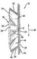
- the body portion 12 of face masks 10are typically manufactured with horizontal folds 22 and 26 so that the body portion 12 may be adjusted vertically or otherwise to allow the body portion 12 to be formed into a chamber with the perimeter of the chamber sealing to the face of the user. All of the layers 20 and 24 of the body portion 12 are folded simultaneously during manufacture of the face mask 10 . Creases 56 and 58 in the layers 20 and 24 of the body portion 12 are therefore nested or aligned with one another both before unfolding of the body portion 12 , as shown in FIG. 1 , and after unfolding as shown in FIG. 2 . It is sometimes the case that the layers 20 and 24 are adhered to one another before folding. Folding of the layers 20 and 24 independently from one another is not done as this technique allegedly adds cost and complexity to the manufacturing process.
- the face maskmay include a body portion with a first layer and a second layer where both the first and second layers have a plurality of folds that form a plurality of first creases in the first layer and a plurality of second creases in the second layer.
- the body portionmay have an outer facing surface and an inner facing surface opposite from the outer facing surface. At least one of the first creases may be misaligned with at least one of the second creases.
- This type of configurationmay be advantageous in that fluid may not be allowed to travel directly through at least one of the first and second creases because these creases are not nested or in alignment with one another.
- a face maskmay be provided that includes a body portion configured to be placed over a mouth and at least part of a nose of a user in order to isolate the mouth and at least part of the nose of the user from the environment.
- the body portionmay have a first layer with a plurality of folds forming a plurality of first creases in which the folds extend across the entire horizontal length of the first layer and are configured to unfold in order to extend the length of the first layer in the vertical direction.
- the body portionmay also have a second layer adjacent with the first layer with a plurality of folds that form a plurality of second creases.
- the folds of the second layermay extend across the entire horizontal length of the second layer and may be configured to unfold in order to extend the length of the second layer in the vertical direction.
- the first creases of the plurality of folds in the first layermay be unnested with the second creases of the plurality of folds in the second layer.
- a face maskmay be provided as discussed above in which all of the first creases of the first layer may be unnested or misaligned with the second creases of the second layer.
- the body portionmay have binding on at least two of the ends of the first and second layers.
- the bindingmay act to limit expansion of the edges of the first and second layers upon unfolding of the folds in the first and second layers.
- a further exemplary embodiment of the face mask as discussed abovemay include a fastening member.
- the fastening membermay be attached to the body portion and may be configured for retaining the body portion onto the face of the user.
- the fastening membermay be a pair of manual tie straps or ear loops.
- a face maskas previously discussed where the body portion may have a third layer in contact with the second layer.
- the third layermay have a plurality of folds that form a plurality of third creases.
- the third layermay form the inner facing surface of the body portion and the first layer may form the outer facing surface of the body portion. Additionally, at least one of the first creases of the first layer may be misaligned with all of the third creases.
- the methodmay include the steps of providing a first layer and a second layer.
- the methodmay also include the step of folding the first layer so as to form a plurality of folds with a plurality of first creases.
- the methodmay include the step of folding the second layer separately from the first layer so as to form a plurality of folds with a plurality of second creases in the second layer.
- Also included in the methodmay be the step of assembling the first layer and the second layer into a body portion of a face mask so that at least one of the first creases is misaligned with the second creases.
- step of assemblingincludes binding at least two of the ends of the first layer to two of the ends of the second layer.
- Another exemplary embodimentresides in a method as previously discussed that further includes the steps of providing a third layer and folding the third layer.
- the third layermay be folded so as to form a plurality of folds with a plurality of third creases in the third layer.
- the methodmay also include the step of assembling the third layer with the first and second layers into a body portion of a face mask so that at least one of the first creases in the first layer is misaligned with the third creases.
- FIG. 1is a partial perspective view of a body portion of a prior face mask with layers having aligned creases in the closed orientation.
- FIG. 2is a partial perspective view of the body portion of FIG. 1 in the opened orientation.
- FIG. 3is a front view of an exemplary embodiment of a face mask in accordance with one exemplary embodiment.
- FIG. 4is a perspective view of the face mask of FIG. 3 shown attached to the face of a user.
- FIG. 5is a partial perspective view of a body portion of a face mask in accordance with one exemplary embodiment that has layers in the closed orientation with creases that are misaligned with one another.
- FIG. 6is a partial perspective view of the body portion of FIG. 5 in the opened orientation.
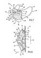
- FIG. 7is a perspective view of an exemplary embodiment of a face mask.
- the face maskincludes an anti-fog strip and a fastening member that is a pair of ear loops.
- FIG. 8is a partial perspective view of a body portion of the face mask in accordance with one exemplary embodiment in the closed orientation.
- the face maskincludes three layers in which the second and third layers have creases that are aligned with one another and are misaligned with the creases of the first layer.
- FIG. 9is a partial perspective view of the body portion of FIG. 8 in the opened orientation.
- FIG. 10is a partial perspective view of a body portion of the face mask in accordance with one exemplary embodiment in the closed orientation.
- the body portionincludes two layers that have creases that are both aligned and misaligned with one another.
- FIG. 11is a partial perspective view of the body portion of FIG. 10 in the opened orientation.
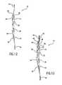
- FIG. 12is a perspective view of a method of forming a body portion in accordance with one exemplary embodiment.
- the first and second layersare assembled with one another and are fixed by way of a binding so that folds of the first and second layer are misaligned.
- FIG. 13is a perspective view of an exemplary embodiment of a method of forming a body portion. An anti-fog strip and a third layer are assembled onto the first and second layers.
- nonwoven fabric or webmeans a web having a structure of individual fibers or threads which are interlaid, but not in an identifiable manner as in a knitted fabric.
- Nonwoven fabrics or webshave been formed from various processes such as, for example, meltblowing processes, spunbonding processes, and bonded carded web processes.
- the basis weight of nonwoven fabricsis usually expressed in ounces of material per square yard (osy) or grams per square meter (gsm) and the fiber diameters are usually expressed in microns. (Note that to convert from osy to gsm, multiply osy by 33.91).
- ultrasonic bondingrefers to a process in which materials (fibers, webs, films, etc.) are joined by passing the materials between a sonic horn and anvil roll.
- materialsfibers, webs, films, etc.
- An example of such a processis illustrated in U.S. Pat. No. 4,374,888 to Bornslaeger, the entire contents of which are incorporated herein by reference in their entirety for all purposes.
- thermal point bondinginvolves passing materials (fibers, webs, films, etc.) to be bonded between a heated calender roll and a heated anvil roll.
- the calender rollis usually, though not always, engraved with a pattern in some way such that the entire fabric is not bonded across its entire surface.
- the surface of the anvil rollis usually flat and/or smooth.
- various patterns for calender rollshave been developed for functional as well as aesthetic reasons.
- the percent bonding areavaries from around 10 percent to around 30 percent of the area of the fabric laminate.
- the bonded areasare typically discrete points or shapes and not interconnected.
- thermal point bondingholds the laminate layers together and imparts integrity and strength to the nonwoven material by bonding filaments and/or fibers together thereby limiting their movement.
- the term “electret” or “electret treating”refers to a treatment that imparts a charge to a dielectric material, such as a polyolefin.
- the chargeincludes layers of positive or negative charges trapped at or near the surface of the polymer, or charge clouds stored in the bulk of the polymer.
- the chargealso includes polarization charges which are frozen in alignment of the dipoles of the molecules.
- Methods of subjecting a material to electret treatingare well known by those skilled in the art. These methods include, for example, thermal, liquid-contact, electron beam, and corona discharge methods.
- One particular technique of subjecting a material to electret treatingis disclosed in U.S. Pat. No. 5,401,466 to Foltz, the entire contents of which are herein incorporated by reference in their entirety for all purposes. This technique involves subjecting a material to a pair of electrical fields wherein the electrical fields have opposite polarities.
- spunbonded fibersrefers to small diameter fibers which are formed by extruding molten thermoplastic material as filaments from a plurality of fine, usually circular capillaries of a spinneret with the diameter of the extruded filaments then being rapidly reduced to fibers as by, for example, in U.S. Pat. No. 4,340,563 to Appel et al., and U.S. Pat. No. 3,692,618 to Dorschner et al., U.S. Pat. No. 3,802,817 to Matsuki et al., U.S. Pat. Nos. 3,338,992 and 3,341,394 to Kinney, U.S. Pat. No.
- Spunbond fibersare generally continuous and have diameters generally greater than about 7 microns, more particularly, between about 10 and about 40 microns.
- meltblown fibersmeans fibers formed by extruding a molten thermoplastic material through a plurality of fine, usually circular, die capillaries as molten threads or filaments into converging high velocity, usually hot, gas (e.g. air) streams which attenuate the filaments of molten thermoplastic material to reduce their diameter, which may be to microfiber diameter. Thereafter, the meltblown fibers are carried by the high velocity gas stream and are deposited on a collecting surface to form a web of randomly disbursed meltblown fibers.
- gase.g. air
- stretch bonded laminaterefers to a composite material having at least two layers in which one layer is a gatherable layer and the other layer is an elastic layer. The layers are joined together when the elastic layer is extended from its original condition so that upon relaxing the layers, the gatherable layer is gathered.
- Such a multilayer composite elastic materialmay be stretched to the extent that the nonelastic material gathered between the bond locations allows the elastic material to elongate.
- One type of stretch bonded laminateis disclosed, for example, by U.S. Pat. No. 4,720,415 to Vander Wielen et al., the entire contents of which are incorporated herein by reference in their entirety for all purposes.
- Other composite elastic materialsare disclosed in U.S. Pat. No.
- neckingor “neck stretching” interchangeably refer to a method of elongating a nonwoven fabric, generally in the machine direction, to reduce its width (cross-machine direction) in a controlled manner to a desired amount.
- the controlled stretchingmay take place under cool, room temperature or greater temperatures and is limited to an increase in overall dimension in the direction being stretched up to the elongation required to break the fabric, which in most cases is about 1.2 to 1.6 times.
- the webretracts toward, but does not return to, its original dimensions.
- necked materialrefers to any material which has undergone a necking or neck stretching process.
- reversibly necked materialrefers to a material that possesses stretch and recovery characteristics formed by necking a material, then heating the necked material, and cooling the material. Such a process is disclosed in U.S. Pat. No. 4,965,122 to Morman, the entire contents of which are incorporated by reference herein in their entirety for all purposes.
- neck bonded laminaterefers to a composite material having at least two layers in which one layer is a necked, non-elastic layer and the other layer is an elastic layer. The layers are joined together when the non-elastic layer is in an extended (necked) condition.
- neck-bonded laminatesare such as those described in U.S. Pat. Nos. 5,226,992, 4,981,747, 4,965,122 and 5,336,545 to Morman, the entire contents of which are incorporated herein by reference in their entirety for all purposes.
- meltblown materialmeans a meltblown material to which at least one other material is added during the meltblown material formation.
- the meltblown materialmay be made of various polymers, including elastomeric polymers.
- additional materialsmay be added to the meltblown fibers during formation, including, for example, pulp, superabsorbent particles, cellulose or staple fibers.
- Coform processesare illustrated in commonly assigned U.S. Pat. No. 4,818,464 to Lau and U.S. Pat. No. 4,100,324 to Anderson et al., the entire contents of which are incorporated herein by reference in their entirety for all purposes.
- the term “elastic”refers to any material, including a film, fiber, nonwoven web, or combination thereof, which upon application of a biasing force, is stretchable to a stretched, biased length which is at least about 150 percent, or one and a half times, its relaxed, unstretched length, and which will recover at least 15 percent of its elongation upon release of the stretching, biasing force.
- Extensible and retractablerefers to the ability of a material to extend upon stretch and retract upon release. Extensible and retractable materials are those which, upon application of a biasing force, are stretchable to a stretched, biased length and which will recover a portion, preferably at least about 15 percent, of their elongation upon release of the stretching, biasing force.
- elastomeror “elastomeric” refer to polymeric materials that have properties of stretchability and recovery.
- the terms “stretch” or “stretched”refers to the ability of a material to extend upon application of a biasing force. Percent stretch is the difference between the initial dimension of a material and that same dimension after the material has been stretched or extended following the application of a biasing force. Percent stretch may be expressed as [(stretched length B initial sample length)/initial sample length] ⁇ 100. For example, if a material having an initial length of one (1) inch is stretched 0.50 inch, that is, to an extended length of 1.50 inches, the material can be said to have a stretch of 50 percent.
- the term “recover” or “recovery”refers to a contraction of a stretched material upon termination of a biasing force following stretching of the material by application of the biasing force. For example, if a material having a relaxed, unbiased length of one (1) inch is elongated 50 percent by stretching to a length of one and one half (1.5) inches the material would have a stretched length that is 150 percent of its relaxed length. If this exemplary stretched material contracted, that is recovered to a length of one and one tenth (1.1) inches after release of the biasing and stretching force, the material would have recovered 80 percent (0.4 inch) of its elongation.
- compositerefers to a material which may be a multicomponent material or a multilayer material. These materials may include, for example, spunbonded-meltblown-spunbonded, stretch bonded laminates, neck bonded laminates, or any combination thereof.
- polymergenerally includes but is not limited to, homopolymers, copolymers, such as for example, block, graft, random and alternating copolymers, terpolymers, etc. and blends and modifications thereof. Furthermore, unless otherwise specifically limited, the term “polymer” shall include all possible geometrical configurations of the molecule. These configurations include, but are not limited to isotactic, syndiotactic and random symmetries.
- ranges and limits mentioned hereininclude all ranges located within, and also all values located under or above the prescribed limits. It is to be also understood that all ranges mentioned herein include all subranges included in the mentioned ranges. For instance, a range from 100-200 also includes ranges from 110-150, 170-190, and 153-162. Further, all limits mentioned herein include all other limits included in the mentioned limit. For example, a limit of up to about 7 also includes a limit of up to about 5, up to about 3, and up to about 4.5.
- a face mask 10has a body portion 12 that includes both a first and second layer 20 and 24 .
- the first and second layers 20 and 24may be arranged so that a plurality of first creases 56 in the folds 22 are misaligned or unnested from a plurality of second creases 58 in the folds 26 .
- Misaligning or unnesting of the creases 56 and 58may improve the fluid resistance of the body portion 12 because doing so will eliminate a potential weak spot in the body portion 12 in that fluid may be prevented from contacting and traveling through the body portion 12 directly from one crease 56 to the other crease 58 .
- FIG. 3shows a front view of the face mask 10 in accordance with one exemplary embodiment.
- the body portion 12may have a first layer 20 with a plurality of folds 22 that extend in a horizontal direction 28 .
- the body portion 12may have a second layer 24 with a plurality of folds 26 that also extend in the horizontal direction 28 .
- a plurality of first creases 56 in the folds 22may be vertically offset from a plurality of creases 58 in the folds 26 in a vertical direction 30 .
- the body portion 12may be configured to be placed over the mouth and at least part of the nose of the user 14 as shown in FIG. 4 so that air exchange through normal respiration passes through the body portion 12 .
- the user 14may unfold the folds 22 and 26 so as to increase the length of the body portion 12 in the vertical direction 30 in order to conform the shape of the body portion 12 to the user's 14 face.
- the body portion 12may be formed into a chamber with the perimeter of the chamber sealing to the face of the user 14 . As shown in the open position in FIG.
- the plurality of first creases 56will be offset from the plurality of second creases 58 so as to improve fluid strike through concerning fluid that contacts the outer facing surface 16 of the body portion 12 and propagates through to an inner facing surface 18 of the body portion 12 that may contact the face of the user 14 .
- first creases 56may be misaligned or unnested with the second creases 58 in accordance with various exemplary embodiments, it is to be understood that in accordance with other exemplary embodiments only one or more of the first creases 56 may be misaligned or unnested with the second creases 58 . Additionally, the creases 56 and 58 may be made in the layers 20 and 24 such that they are not completely parallel to one another but may be at angles so as to intersect. In this regard, one or more of the first creases 56 may intersect one or more of the second creases 58 at one or more locations.
- FIG. 5is a partial cut-a-way view of an exemplary embodiment of the face mask 10 in which the body portion 12 is in the closed or unopened positioned.
- the plurality of folds 22 and 26 in the first and second layers 20 and 24may be of any type commonly known to those having ordinary skill in the art.
- the side edges of the first and second layers 20 and 24may be held together, for example, by ultrasonic bonding, as represented by ultrasonic bond dimples 54 . It is to be understood that other ultrasonic bonding patterns may be employed to facilitate holding of the sides of the layers 20 and 24 to one another.
- FIG. 3shows binding 32 and 34 on either side of the body portion 12 that is used to constrain the layers 20 and 24 . Additionally, binding 42 may be located on the top edge of the body portion 12 and binding 44 may be located on the bottom edge of the body portion 12 .
- the bindings 32 , 34 , 42 and 44may be of various types in accordance with other exemplary embodiments.
- FIG. 6shows the layers 20 and 24 after unfolding of the folds 22 and 26 . All of the first creases 56 are misaligned or unested with the second creases 58 . Although some of the first creases 56 will intersect some of the second creases 58 , complete alignment or nesting of the creases 56 and 58 is avoided thus rendering the body portion 12 more fluid resistant.
- an anti-fog strip 46may be attached to the second layer 24 and run along the horizontal direction 28 of the body portion 12 as shown in FIG. 7 .
- the anti-fog strip 46may be attached by way of the binding 42 or may be attached to the second layer 24 in any manner commonly known to one having ordinary skill in the art such as through adhesion or staples.
- the anti-fog strip 46may assist in redirecting exhaled breath of the user 14 ( FIG. 4 ) into the layers 20 and 24 of the body portion 12 and away from the eyes of the user 14 . It is sometimes the case that exhaled breath will cause fogging of eye wear or a face shield if worn by a user 14 .
- the anti-fog strip 46may act to seal the periphery of the upper edge of the body portion 12 so that warm, moist exhaled breath cannot be directed therethrough.
- the anti-fog strip 46may be configured as that shown in U.S. Pat. No. 6,520,181 to Baumann, et al., the entire contents of which are incorporated herein by reference in their entirety for all purposes.
- FIG. 8shows an exemplary embodiment in which a third layer 38 may be incorporated into the body portion 12 .
- the third layer 38may have a plurality of folds 40 that run in the horizontal direction 28 .
- a plurality of third creases 60may be present in the folds 40 and may be aligned with or nested with the second creases 58 of the second layer 24 .
- the first creases 56 of the first layer 20are offset from and are not aligned with the second and third creases 58 and 60 .
- the body portion 12is shown opened in FIG. 9 .
- the second and third creases 58 and 60are aligned with one another but are vertically offset from the first creases 56 so that the body portion 12 will enjoy increased fluid resistance.
- the third creases 60may be offset from both the first creases 56 and the second creases 58 so that all of the creases 56 , 58 and 60 may be offset from one another.
- the creases 56 , 58 and 60may or may not intersect one another in accordance with various exemplary embodiments of the present invention.
- the first creases 56may be aligned with the third creases 60 while both the first and third creases 56 and 60 are offset from the second creases 58 .
- any number of additional layersmay be employed that may or may not have folds that may or may not be aligned or nested with those of the first, second and third layers 20 , 24 and 38 .
- FIG. 10shows an exemplary embodiment of the body portion 12 of the face mask 10 in which a first and second layer 20 and 24 are present.
- some of the first creases 56may be aligned or nested with the second creases 58 while other first creases 56 may be misaligned or unnested with other second creases 58 .
- FIG. 11shows the body portion 12 of FIG. 10 in an unfolded orientation.
- certain first creases 56may or may not be nested or aligned with certain second creases 58 .
- the first layer 20 and the second layer 24may each pass through their own set of folding boards before the layers 20 and 24 are brought together and configured with one another.
- the design and alignment of the individual folding boardsmay be adjusted to ensure that a desired alignment of the first and second creases 56 and 58 is obtained.
- the folding boardsmay be situated so that the first layer 20 is folded vertically above or below the second layer 24 .
- the layers 20 and 24may then be brought into engagement with one another in one exemplary embodiment.
- FIG. 12shows the layers 20 and 24 in contact and fixed to one another by way of bindings 42 and 44 in accordance with one exemplary embodiment.
- bindings 32 and 34FIG. 3
- bindings 32 and 34may also be added or used in another exemplary embodiment.
- FIG. 13Two additional steps that may be included are shown in FIG. 13 in which an anti-fog strip 46 may be attached to the first layer 20 .
- a third layer 38that may be folded by one of the same folding boards responsible for folding the first layer 20 or the second layer 24 may also be provided and may be attached to the first and second layers 20 and 24 and thus incorporated into the body portion 12 .
- the third layer 38may be folded via a separate folding board so as to result in a body portion 12 in which the first, second and third creases 56 , 58 and 60 are misaligned or unnested with one another.
- Multiple layers of the face mask 10may be joined by various methods, including adhesive bonding, thermal point bonding, ultrasonic bonding or by any other method commonly know to one having ordinary skill in the art.
- any of the layers 20 , 24 and/or 38may be a filtration media configured to prevent the passage of pathogens through the body portion 12 while still allowing for the passage of air in order to allow the user 14 ( FIG. 4 ) to breathe.
- just the second layer 24is a filtration layer.
- the layers 20 , 24 and 38may be configured so that any of the layers 20 , 24 and 38 include filtration media.
- both the first layer 20 and the second layer 24may include filtration media in accordance with one exemplary embodiment of the present invention.
- the body portion 12 and/or the entire face mask 10may be made of any number of layers in accordance with other exemplary embodiments.
- the body portion 12may be of a variety of styles and geometries, such as, but not limited to, flat half masks, pleated face masks, cone masks, duckbill style masks, trapezoidally shaped masks, etc.
- the styles shown in the Figuresare for illustrative purposes only.
- the body portion 12may be configured as that shown in U.S. Pat. No. 6,484,722 to Bostock, et al., the entire contents of which are incorporated by reference herein in their entirety for all purposes.
- the face mask 10may isolate the mouth and the nose of the user 14 ( FIG. 4 ) from the environment. Additionally, the configuration of the face mask 10 may be different in accordance with various exemplary embodiments. In this regard, the face mask 10 may be made such that it covers both the eyes, hair, nose, throat, and mouth of the user 14 . As such, face masks 10 are included that cover areas above and beyond simply the nose and mouth of the user 14 .
- the face mask 10may be attached to the user 14 by a fastening member 36 that may be a pair of tie straps 48 as shown in FIG. 4 that are wrapped around the head of the user 14 (and a hair cap 50 if worn by the user 14 ) and are connected to one another.
- a fastening member 36may be a pair of tie straps 48 as shown in FIG. 4 that are wrapped around the head of the user 14 (and a hair cap 50 if worn by the user 14 ) and are connected to one another.
- the face mask 10may be attached to the user 14 by a fastening member 36 that may be elastic bands wrapped around the head of the user 14 , a hook and loop type fastener arrangement, a pair of ear loops, or a connection directly attaching the face mask 10 to the hair cap 50 .
- FIG. 7shows the fastening member 36 as a pair of ear loops 62 that may be fastened to the ears of the user 14 ( FIG. 4 ) so as to retain the face mask 10 .
- the exemplary embodiment shown in FIG. 7includes a series of structural elements (stays) 52 incorporated into the body portion 12 in order to provide for a face mask 10 with different desired characteristics.
- the stays 52may provide for structural rigidity of the body portion 12 , and may also be shaped in order to help seal the periphery of the body portion 12 .
- a stay 52may be employed within the body portion 12 in order to help conform the body portion 12 around the nose of the user 14 ( FIG. 4 ).
- the stay or stays 52may be used to help seal the perimeter of the body portion 12 around he face of the user 14 and/or to help maintain the shape of a breathing chamber and to keep the breathing chamber from contacting the face of the wearer.
- a stay 52may be employed in order to better shape the body portion 12 around the chin of the user 14 ( FIG. 4 ).
- the stays 52may allow for a better fit of the body portion 12 and may be used to help form a chamber around the mouth and/or nose of the user 14 .
- the stays 52may help achieve a better fit so as to prevent the transfer of pathogens through any possible openings along the perimeter of the body portion 12 .
- a series of stays 52 incorporated into a face mask 10is disclosed in U.S. Pat. No. 5,699,791, to Sukiennik et al., the entire contents of which are incorporated herein by reference in their entirety for all purposes.
- Stays 52may be made of an elongated malleable member such as a metal wire or an aluminum band that may be formed into a rigid shape in order to impart this shape into the body portion 12 of the face mask 10 .
- a metal wire or an aluminum bandthat may be formed into a rigid shape in order to impart this shape into the body portion 12 of the face mask 10 .
- various exemplary embodimentsexist that do not include stays 52 .
- the face mask 10may also incorporate any combination of known face mask 10 features, such as visors or shields, anti-fog strips 46 , sealing films, beard covers, etc.
- face mask 10 featuressuch as visors or shields, anti-fog strips 46 , sealing films, beard covers, etc.
- Exemplary faces masks and features incorporated into face masksare described and shown, for example, in the following U.S. Pat. Nos. 4,802,473; 4,969,457; 5,322,061; 5,383,450; 5,553,608; 5,020,533; and 5,813,398. The entire contents of these patents are incorporated by reference herein in their entirety for all purposes.
- the mask face 10may be composed of layers 20 , 24 and 38 as shown for instance in FIG. 8 .
- These layers 20 , 24 and 38may be constructed from various materials known to those skilled in the art.
- the first layer 20 of the body portion 12may be any nonwoven web, such as a spunbonded, meltblown, or coform nonwoven web, a bonded carded web, or a wetlaid composite.
- the second layer 24 of the body portion 12 and first layer 20may be a necked nonwoven web or a reversibly necked nonwoven web.
- the layers 20 , 24 and 38may be made of the same material or of different materials. SMS may be used to comprise the layers 20 , 24 and 38 . SMS is a meltblown layer made of meltblown fibers, between two spunbond layers made of spunbond fibers.
- polyethylenessuch as Dow Chemical's ASPUN® 6811A linear polyethylene, 2553 LLDPE and 25355, and 12350 polyethylene are such suitable polymers.
- Fiber forming polypropylenesinclude, for example, Exxon Chemical Company's Escorene® PD 3445 polypropylene and Basell's PF-304.
- Many other suitable polyolefinsare commercially available as are known to those having ordinary skill in the art.
- the various materials used in construction of the face mask 10may exemplarily include a necked nonwoven web, a reversibly necked nonwoven material, a neck bonded laminate, and elastic materials such as an elastic coform material, an elastic meltblown nonwoven web, a plurality of elastic filaments, an elastic film, or a combination thereof.
- elastic materialshave been incorporated into composites, for example, in U.S. Pat. No. 5,681,645 to Strack et al., U.S. Pat. No. 5,493,753 to Levy et al., U.S. Pat. No. 4,100,324 to Anderson et al., and in U.S. Pat. No.
- the filmmay be perforated to ensure that the user 14 ( FIG. 4 ) can breathe through the body portion 12 if the face mask 10 is desired to be breathable in this location.
- the filmneed not be elastic in accordance with other exemplary embodiments.
- the layers 20 , 24 and/or 38 when configured as a filtration layermay be a meltblown nonwoven web and, in some embodiments, may be electret treated.
- Electret treatmentresults in a charge being applied to the layers 20 , 24 and/or 38 that further increases filtration efficiency by drawing particles to be filtered toward the layers 20 , 24 and/or 38 by virtue of their electrical charge.
- Electret treatmentcan be carried out by a number of different techniques. One technique is described in U.S. Pat. No. 5,401,446 to Tsai et al., the entire contents of which are incorporated herein by reference in their entirety for all purposes. Other methods of electret treatment are known in the art, such as that described in U.S. Pat. No.
- the layers 20 , 24 and/or 38may be made of an expanded polytetrafluoroethylene (PTFE) membrane, such as those manufactured by W. L. Gore & Associates. A more complete description of the construction and operation of such materials can be found in U.S. Pat. Nos. 3,953,566 and 4,187,390 to Gore, the entire contents of which are incorporated herein by reference in their entirety for all purposes.
- PTFEpolytetrafluoroethylene
- the expanded polytetrafluoroethylene membranemay be incorporated into a multi-layer composite, including, but not limited to, an outer nonwoven web first layer 20 , an extensible and retractable layer, and an inner second layer 24 comprising a nonwoven web.
- the face mask 10may be made of an elastic material that allows the face mask 10 to stretch in one or more directions.
- the use of an elastic material incorporated into the body portion 12may allow for fuller coverage of the user's 14 face and provide for more flexibility in accommodating variously sized faces of the users 14 .
- the face mask 10may be stretched over the nose, mouth, and/or face of the user 14 .
- the body portion 12may be made of an inelastic material. As such, the material that makes up the face mask 10 may exhibit elastic or inelastic characteristics depending upon the user's 14 needs.
- the body portion 12 of the face mask 10may be configured so that it is capable of stretching across the face of the user 14 from ear to ear and/or nose to chin.
- the ability of the body portion 12 to stretch and recovermay provide the face mask 10 with better sealing capabilities and a more comfortable fit than face masks 10 that have an inelastic body portion 12 .
- the body portion 12In order for the body portion 12 to stretch and recover, the body portion 12 must have at least one layer or a material that has stretch and recovery properties.
- the entire face mask 10may be composed of a material that has stretch and recovery properties in other exemplary embodiments.
- the percent recoverymay be about 15% and the percent stretch may be about 15-65%, in other embodiments the percent recovery may be about 20-40% stretch, and in still other embodiments the percent recovery may be about 25-30% stretch.
- Elastomeric thermoplastic polymersmay be used in the face mask 10 of the present invention and may include block copolymers having the general formula A-B-A′ or A-B, where A and A′ are each a thermoplastic polymer endblock which contains a styrenic moiety such as a poly (vinyl arene) and where B is an elastomeric polymer midblock such as a conjugated diene or a lower alkene polymer.
- Block copolymers of the A-B-A′ typecan have different or the same thermoplastic block polymers for the A and A′ blocks, and the present block copolymers are intended to embrace linear, branched and radial block copolymers.
- elastomeric resinsexamples include those made from block copolymers such as polyurethanes, copolyether esters, polyamide polyether block copolymers, ethylene vinyl acetates (EVA), block copolymers having the general formula A-B-A′ or A-B like copoly(styrene/ethylene-butylene), styrene-poly(ethylene-propylene)-styrene, styrene-poly(ethylene-butylene)-styrene, (polystyrene/poly(ethylene-butylene)/polystyrene, poly(styrene/ethylene-butylene/styrene) and the like.
- block copolymerssuch as polyurethanes, copolyether esters, polyamide polyether block copolymers, ethylene vinyl acetates (EVA), block copolymers having the general formula A-B-A′ or A-B like copoly(s
- One or more layers 20 , 24 or 38 , as shown for example in FIG. 8 , of the face mask 10may be made of a composite that is a neck bonded laminate in certain exemplary embodiments.
- the neck bonded laminatemay utilize a necked material or a reversibly necked material.
- the necking processtypically involves unwinding a material from a supply roll and passing it through a brake nip roll assembly at a given linear speed.
- a take-up roll or nipoperating at a linear speed greater than that of the brake nip roll, draws the material and generates the tension needed to elongate and neck the fabric.
- the stretched materialis heated and cooled while in a stretched condition.
- the heating and cooling of the stretched materialcauses additional crystallization of the polymer and imparts a heat set.
- the necked material or reversibly necked materialis then bonded to an elastic material. Afterwards, the layer may be folded in order to form folds 22 , 26 or 40 .
- the resulting necked compositeis extensible and retractable in the cross-machine direction, that is the direction perpendicular to the direction the material is moving when it is produced. Upon extension and release, the elastic material provides the force needed for the extended composite to retract.
- the composite making up one or more of the layers 20 , 24 or 38may be a stretch bonded laminate.
- a stretch bonded laminateis formed by providing an elastic material, such as a nonwoven web, filaments, or film, extending the elastic material, attaching it to a gatherable material, and releasing the resulting laminate.
- a stretch bonded laminateis extensible and retractable in the machine direction, that is the direction that the material is moving when it is produced.
- a composite with multiple layersmay be formed by providing the elastic layer and the gatherable layers, and subjecting it to this process either simultaneously or stepwise.
- the stretch bonded laminatemay also include a necked material that is extensible and retractable in the cross-direction such that the overall laminate is extensible and retractable in at least two dimensions.
- an elastomeric meltblown nonwoven webis provided, the elastomeric meltblown nonwoven web is then extended in the machine direction, and the necked spunbonded nonwoven material is attached to the elastomeric meltblown nonwoven web by thermal bonding while the elastomeric meltblown web is extended.
- the resulting compositeis extensible and retractable in both the cross-direction and machine direction, due to the extensibility of the necked material and the use of the stretch bonding process, respectively.
- the compositemay then be folded in order to form folds 22 , 26 or 40 and attached to or otherwise incorporated with one or more layers to make up the body portion 12 .
- one of the layers of the compositemay be folded with folds 22 , 26 or 40 before attachment to the other layer of the composite having folds 22 , 26 or 40 offset from the folds 22 , 26 or 40 of the previous layer of the composite.
- the compositemay contain various chemical additives or topical chemical treatments in or on one or more layers, including, but not limited to, surfactants, colorants, antistatic chemicals, antifogging chemicals, fluorochemical blood or alcohol repellents, lubricants, or antimicrobial treatments.
Landscapes
- Health & Medical Sciences (AREA)
- General Health & Medical Sciences (AREA)
- Physical Education & Sports Medicine (AREA)
- Engineering & Computer Science (AREA)
- Textile Engineering (AREA)
- Respiratory Apparatuses And Protective Means (AREA)
Abstract
Description
Claims (14)
Priority Applications (1)
| Application Number | Priority Date | Filing Date | Title |
|---|---|---|---|
| US11/020,738US7725948B2 (en) | 2004-12-22 | 2004-12-22 | Face mask with offset folding for improved fluid resistance |
Applications Claiming Priority (1)
| Application Number | Priority Date | Filing Date | Title |
|---|---|---|---|
| US11/020,738US7725948B2 (en) | 2004-12-22 | 2004-12-22 | Face mask with offset folding for improved fluid resistance |
Publications (2)
| Publication Number | Publication Date |
|---|---|
| US20060130214A1 US20060130214A1 (en) | 2006-06-22 |
| US7725948B2true US7725948B2 (en) | 2010-06-01 |
Family
ID=36593830
Family Applications (1)
| Application Number | Title | Priority Date | Filing Date |
|---|---|---|---|
| US11/020,738Active2027-12-15US7725948B2 (en) | 2004-12-22 | 2004-12-22 | Face mask with offset folding for improved fluid resistance |
Country Status (1)
| Country | Link |
|---|---|
| US (1) | US7725948B2 (en) |
Cited By (16)
| Publication number | Priority date | Publication date | Assignee | Title |
|---|---|---|---|---|
| US8398234B2 (en) | 2011-05-03 | 2013-03-19 | Kimberly-Clark Worldwide, Inc. | Electro-thermal antifog optical devices |
| US8794238B2 (en) | 2010-12-28 | 2014-08-05 | 3M Innovative Properties Company | Splash-fluid resistant filtering face-piece respirator |
| RU2632636C2 (en)* | 2016-03-30 | 2017-10-06 | Алла Ивановна Вдовенко | Medical antimicrobial mask, method for its manufacture and applications |
| US20170360125A1 (en)* | 2016-06-20 | 2017-12-21 | Ronald Tuan | Gauze mask with folding lines capable of enabling the gauze mask to be folded into a flat package or unfolded into a three dimensional configuration |
| US10639506B2 (en) | 2013-08-20 | 2020-05-05 | 3M Innovative Properties Company | Personal respiratory protection device |
| US11064745B1 (en)* | 2020-11-12 | 2021-07-20 | United Arab Emirates University | Face mask with separate inhaling and exhaling portions |
| US11154735B2 (en) | 2013-08-20 | 2021-10-26 | 3M Innovative Properties Company | Personal respiratory protection device |
| US11241595B2 (en) | 2013-08-20 | 2022-02-08 | 3M Innovative Properties Company | Personal respiratory protection device |
| US11247079B2 (en) | 2013-08-20 | 2022-02-15 | 3M Innovative Properties Company | Personal respiratory protection device |
| US20230102993A1 (en)* | 2021-09-27 | 2023-03-30 | Vyasateja J N | Face shield for covering facial region of subject |
| US11690767B2 (en) | 2014-08-26 | 2023-07-04 | Curt G. Joa, Inc. | Apparatus and methods for securing elastic to a carrier web |
| US11701268B2 (en) | 2018-01-29 | 2023-07-18 | Curt G. Joa, Inc. | Apparatus and method of manufacturing an elastic composite structure for an absorbent sanitary product |
| US11744744B2 (en) | 2019-09-05 | 2023-09-05 | Curt G. Joa, Inc. | Curved elastic with entrapment |
| US11925538B2 (en) | 2019-01-07 | 2024-03-12 | Curt G. Joa, Inc. | Apparatus and method of manufacturing an elastic composite structure for an absorbent sanitary product |
| US12336889B2 (en) | 2020-02-17 | 2025-06-24 | Curt G. Joa, Inc. | Elastic composite structure for an absorbent sanitary product and an apparatus and method for making said elastic composite structure |
| US12433797B2 (en) | 2019-09-04 | 2025-10-07 | Curt G. Joa, Inc. | Elastic entrapment with waist cap bonding |
Families Citing this family (16)
| Publication number | Priority date | Publication date | Assignee | Title |
|---|---|---|---|---|
| US20090126064A1 (en)* | 2007-10-17 | 2009-05-21 | Reaux Brian K | Mask and Face Shield |
| US20090151733A1 (en)* | 2007-12-13 | 2009-06-18 | Welchel Debra N | Respirator with stretch-panels |
| US8113201B2 (en) | 2008-06-30 | 2012-02-14 | Kimberly-Clark Worldwide, Inc. | Collapse resistant respirator |
| JP5436262B2 (en)* | 2010-02-19 | 2014-03-05 | ユニ・チャーム株式会社 | mask |
| JP2011194067A (en)* | 2010-03-19 | 2011-10-06 | Three M Innovative Properties Co | Mask with leak preventing section |
| US20110296584A1 (en)* | 2010-06-03 | 2011-12-08 | Chin-Feng Kuo | Mask that Provides a Comfortable Sensation to a User |
| US20130186785A1 (en)* | 2012-01-19 | 2013-07-25 | Michelle S. Alfred | Garment shield device |
| US20130291877A1 (en)* | 2012-05-07 | 2013-11-07 | 3M Innovative Properties Company | Respirator having mottled appearance |
| US9603395B2 (en)* | 2013-08-29 | 2017-03-28 | 3M Innovative Properties Company | Filtering face-piece respirator having darted mask body |
| USD746439S1 (en) | 2013-12-30 | 2015-12-29 | Kimberly-Clark Worldwide, Inc. | Combination valve and buckle set for disposable respirators |
| US11122841B2 (en)* | 2019-08-16 | 2021-09-21 | Alexander Chieruen Tsuei | Face mask and method for manufacturing thereof |
| DE102020109526A1 (en) | 2020-04-03 | 2021-10-07 | Gertrud Fröhlich | Mouthguard |
| CN213604548U (en)* | 2020-06-13 | 2021-07-06 | 带路歌(深圳)技术有限公司 | Single-layer folding multi-layer mask |
| KR20220017163A (en)* | 2020-08-04 | 2022-02-11 | 박이빛 | Mask with ePTFE membrane |
| US11871802B1 (en)* | 2022-08-17 | 2024-01-16 | Integrated Pharma Services, Llc | Pleating spacer and its use to provide improved facial masks and respirators |
| US12303725B2 (en)* | 2023-01-30 | 2025-05-20 | Shirley Doloris Stradford | Nose mask |
Citations (56)
| Publication number | Priority date | Publication date | Assignee | Title |
|---|---|---|---|---|
| US3338992A (en) | 1959-12-15 | 1967-08-29 | Du Pont | Process for forming non-woven filamentary structures from fiber-forming synthetic organic polymers |
| US3341394A (en) | 1966-12-21 | 1967-09-12 | Du Pont | Sheets of randomly distributed continuous filaments |
| US3502763A (en) | 1962-02-03 | 1970-03-24 | Freudenberg Carl Kg | Process of producing non-woven fabric fleece |
| US3542615A (en) | 1967-06-16 | 1970-11-24 | Monsanto Co | Process for producing a nylon non-woven fabric |
| US3692618A (en) | 1969-10-08 | 1972-09-19 | Metallgesellschaft Ag | Continuous filament nonwoven web |
| US3802817A (en) | 1969-10-01 | 1974-04-09 | Asahi Chemical Ind | Apparatus for producing non-woven fleeces |
| US3849241A (en) | 1968-12-23 | 1974-11-19 | Exxon Research Engineering Co | Non-woven mats by melt blowing |
| US3884227A (en)* | 1973-01-29 | 1975-05-20 | Blessings Products Inc | Disposable surgical mask |
| US3953566A (en) | 1970-05-21 | 1976-04-27 | W. L. Gore & Associates, Inc. | Process for producing porous products |
| US4100324A (en) | 1974-03-26 | 1978-07-11 | Kimberly-Clark Corporation | Nonwoven fabric and method of producing same |
| US4215682A (en) | 1978-02-06 | 1980-08-05 | Minnesota Mining And Manufacturing Company | Melt-blown fibrous electrets |
| US4259748A (en) | 1980-04-24 | 1981-04-07 | Miller Anna K | Moisture absorbent mask covering the face, neck and ears |
| US4340563A (en) | 1980-05-05 | 1982-07-20 | Kimberly-Clark Corporation | Method for forming nonwoven webs |
| US4374888A (en) | 1981-09-25 | 1983-02-22 | Kimberly-Clark Corporation | Nonwoven laminate for recreation fabric |
| US4375718A (en) | 1981-03-12 | 1983-03-08 | Surgikos, Inc. | Method of making fibrous electrets |
| US4443513A (en) | 1982-02-24 | 1984-04-17 | Kimberly-Clark Corporation | Soft thermoplastic fiber webs and method of making |
| US4592815A (en) | 1984-02-10 | 1986-06-03 | Japan Vilene Co., Ltd. | Method of manufacturing an electret filter |
| US4631933A (en) | 1984-10-12 | 1986-12-30 | Minnesota Mining And Manufacturing Company | Stitch-bonded thermal insulating fabrics |
| US4652487A (en) | 1985-07-30 | 1987-03-24 | Kimberly-Clark Corporation | Gathered fibrous nonwoven elastic web |
| US4655760A (en) | 1985-07-30 | 1987-04-07 | Kimberly-Clark Corporation | Elasticized garment and method of making the same |
| US4657802A (en) | 1985-07-30 | 1987-04-14 | Kimberly-Clark Corporation | Composite nonwoven elastic web |
| US4720415A (en) | 1985-07-30 | 1988-01-19 | Kimberly-Clark Corporation | Composite elastomeric material and process for making the same |
| US4781966A (en) | 1986-10-15 | 1988-11-01 | Kimberly-Clark Corporation | Spunlaced polyester-meltblown polyetherester laminate |
| US4789699A (en) | 1986-10-15 | 1988-12-06 | Kimberly-Clark Corporation | Ambient temperature bondable elastomeric nonwoven web |
| US4802473A (en) | 1983-11-07 | 1989-02-07 | Tecnol, Inc. | Face mask with ear loops |
| US4818464A (en) | 1984-08-30 | 1989-04-04 | Kimberly-Clark Corporation | Extrusion process using a central air jet |
| US4874659A (en) | 1984-10-24 | 1989-10-17 | Toray Industries | Electret fiber sheet and method of producing same |
| US4891957A (en) | 1987-06-22 | 1990-01-09 | Kimberly-Clark Corporation | Stitchbonded material including elastomeric nonwoven fibrous web |
| US4965122A (en) | 1988-09-23 | 1990-10-23 | Kimberly-Clark Corporation | Reversibly necked material |
| US4969457A (en) | 1987-10-02 | 1990-11-13 | Tecnol, Inc. | Body fluids barrier mask |
| US4981747A (en) | 1988-09-23 | 1991-01-01 | Kimberly-Clark Corporation | Composite elastic material including a reversibly necked material |
| US5020533A (en) | 1987-10-02 | 1991-06-04 | Tecnol, Inc. | Face mask with liquid and glare resistant visor |
| US5114781A (en) | 1989-12-15 | 1992-05-19 | Kimberly-Clark Corporation | Multi-direction stretch composite elastic material including a reversibly necked material |
| US5226992A (en) | 1988-09-23 | 1993-07-13 | Kimberly-Clark Corporation | Process for forming a composite elastic necked-bonded material |
| US5244482A (en) | 1992-03-26 | 1993-09-14 | The University Of Tennessee Research Corporation | Post-treatment of nonwoven webs |
| US5322061A (en) | 1992-12-16 | 1994-06-21 | Tecnol Medical Products, Inc. | Disposable aerosol mask |
| US5383450A (en) | 1987-10-02 | 1995-01-24 | Tcnl Technologies, Inc. | Liquid shield visor for a surgical mask |
| US5401466A (en) | 1993-06-01 | 1995-03-28 | Miles Inc. | Device for the direct measurement of low density lipoprotein cholesterol |
| US5492753A (en) | 1992-12-14 | 1996-02-20 | Kimberly-Clark Corporation | Stretchable meltblown fabric with barrier properties |
| US5493753A (en) | 1995-01-23 | 1996-02-27 | Steamatic, Inc. | Vacuum cleaning system with water extraction lid |
| US5540976A (en) | 1995-01-11 | 1996-07-30 | Kimberly-Clark Corporation | Nonwoven laminate with cross directional stretch |
| US5553608A (en) | 1994-07-20 | 1996-09-10 | Tecnol Medical Products, Inc. | Face mask with enhanced seal and method |
| US5681645A (en) | 1990-03-30 | 1997-10-28 | Kimberly-Clark Corporation | Flat elastomeric nonwoven laminates |
| US5699791A (en)* | 1996-06-04 | 1997-12-23 | Kimberley Clark Corporation | Universal fit face mask |
| US5813398A (en) | 1996-03-29 | 1998-09-29 | Tecnol Medical Products, Inc. | Combined anti fog and anti glare features for face masks |
| US6062220A (en) | 1998-03-10 | 2000-05-16 | American Threshold Industries, Inc. | Reduced fogging absorbent core face mask |
| US6412486B1 (en)* | 1999-07-09 | 2002-07-02 | Leonard W. Glass | Disposable filtering face mask and method of making same |
| US6474336B1 (en)* | 2000-03-20 | 2002-11-05 | Michael Wolfe | Mini pleated face mask |
| US6484722B2 (en) | 1995-09-11 | 2002-11-26 | 3M Innovative Properties Company | Flat-folded personal respiratory protection devices and processes for preparing same |
| US6520181B2 (en) | 1998-03-16 | 2003-02-18 | 3M Innovative Properties Company | Anti-fog face mask |
| US6644314B1 (en) | 2000-11-17 | 2003-11-11 | Kimberly-Clark Worldwide, Inc. | Extensible and retractable face mask |
| US20040078869A1 (en) | 2002-10-25 | 2004-04-29 | Bell Daryl Steven | Face mask having hook and loop type fastener |
| US20040121107A1 (en) | 2002-12-19 | 2004-06-24 | Bell Daryl Steven | Dispensing assembly and method for producing single piece face mask |
| US20040237964A1 (en)* | 1995-03-09 | 2004-12-02 | 3M Innovative Properties Company | Flat-folded personal respiratory protection devices and processes for preparing same |
| US6827764B2 (en)* | 2002-07-25 | 2004-12-07 | 3M Innovative Properties Company | Molded filter element that contains thermally bonded staple fibers and electrically-charged microfibers |
| US20060137691A1 (en)* | 2004-12-23 | 2006-06-29 | Kimberly-Clark Worldwide, Inc. | Face mask with anti-fog folding |
- 2004
- 2004-12-22USUS11/020,738patent/US7725948B2/enactiveActive
Patent Citations (59)
| Publication number | Priority date | Publication date | Assignee | Title |
|---|---|---|---|---|
| US3338992A (en) | 1959-12-15 | 1967-08-29 | Du Pont | Process for forming non-woven filamentary structures from fiber-forming synthetic organic polymers |
| US3502763A (en) | 1962-02-03 | 1970-03-24 | Freudenberg Carl Kg | Process of producing non-woven fabric fleece |
| US3341394A (en) | 1966-12-21 | 1967-09-12 | Du Pont | Sheets of randomly distributed continuous filaments |
| US3542615A (en) | 1967-06-16 | 1970-11-24 | Monsanto Co | Process for producing a nylon non-woven fabric |
| US3849241A (en) | 1968-12-23 | 1974-11-19 | Exxon Research Engineering Co | Non-woven mats by melt blowing |
| US3802817A (en) | 1969-10-01 | 1974-04-09 | Asahi Chemical Ind | Apparatus for producing non-woven fleeces |
| US3692618A (en) | 1969-10-08 | 1972-09-19 | Metallgesellschaft Ag | Continuous filament nonwoven web |
| US3953566A (en) | 1970-05-21 | 1976-04-27 | W. L. Gore & Associates, Inc. | Process for producing porous products |
| US4187390A (en) | 1970-05-21 | 1980-02-05 | W. L. Gore & Associates, Inc. | Porous products and process therefor |
| US3884227A (en)* | 1973-01-29 | 1975-05-20 | Blessings Products Inc | Disposable surgical mask |
| US4100324A (en) | 1974-03-26 | 1978-07-11 | Kimberly-Clark Corporation | Nonwoven fabric and method of producing same |
| US4215682A (en) | 1978-02-06 | 1980-08-05 | Minnesota Mining And Manufacturing Company | Melt-blown fibrous electrets |
| US4259748A (en) | 1980-04-24 | 1981-04-07 | Miller Anna K | Moisture absorbent mask covering the face, neck and ears |
| US4340563A (en) | 1980-05-05 | 1982-07-20 | Kimberly-Clark Corporation | Method for forming nonwoven webs |
| US4375718A (en) | 1981-03-12 | 1983-03-08 | Surgikos, Inc. | Method of making fibrous electrets |
| US4374888A (en) | 1981-09-25 | 1983-02-22 | Kimberly-Clark Corporation | Nonwoven laminate for recreation fabric |
| US4443513A (en) | 1982-02-24 | 1984-04-17 | Kimberly-Clark Corporation | Soft thermoplastic fiber webs and method of making |
| US4802473A (en) | 1983-11-07 | 1989-02-07 | Tecnol, Inc. | Face mask with ear loops |
| US4592815A (en) | 1984-02-10 | 1986-06-03 | Japan Vilene Co., Ltd. | Method of manufacturing an electret filter |
| US4818464A (en) | 1984-08-30 | 1989-04-04 | Kimberly-Clark Corporation | Extrusion process using a central air jet |
| US4631933A (en) | 1984-10-12 | 1986-12-30 | Minnesota Mining And Manufacturing Company | Stitch-bonded thermal insulating fabrics |
| US4874659A (en) | 1984-10-24 | 1989-10-17 | Toray Industries | Electret fiber sheet and method of producing same |
| US4652487A (en) | 1985-07-30 | 1987-03-24 | Kimberly-Clark Corporation | Gathered fibrous nonwoven elastic web |
| US4655760A (en) | 1985-07-30 | 1987-04-07 | Kimberly-Clark Corporation | Elasticized garment and method of making the same |
| US4657802A (en) | 1985-07-30 | 1987-04-14 | Kimberly-Clark Corporation | Composite nonwoven elastic web |
| US4720415A (en) | 1985-07-30 | 1988-01-19 | Kimberly-Clark Corporation | Composite elastomeric material and process for making the same |
| US4781966A (en) | 1986-10-15 | 1988-11-01 | Kimberly-Clark Corporation | Spunlaced polyester-meltblown polyetherester laminate |
| US4789699A (en) | 1986-10-15 | 1988-12-06 | Kimberly-Clark Corporation | Ambient temperature bondable elastomeric nonwoven web |
| US4891957A (en) | 1987-06-22 | 1990-01-09 | Kimberly-Clark Corporation | Stitchbonded material including elastomeric nonwoven fibrous web |
| US5383450A (en) | 1987-10-02 | 1995-01-24 | Tcnl Technologies, Inc. | Liquid shield visor for a surgical mask |
| US5020533A (en) | 1987-10-02 | 1991-06-04 | Tecnol, Inc. | Face mask with liquid and glare resistant visor |
| US4969457A (en) | 1987-10-02 | 1990-11-13 | Tecnol, Inc. | Body fluids barrier mask |
| US4981747A (en) | 1988-09-23 | 1991-01-01 | Kimberly-Clark Corporation | Composite elastic material including a reversibly necked material |
| US5226992A (en) | 1988-09-23 | 1993-07-13 | Kimberly-Clark Corporation | Process for forming a composite elastic necked-bonded material |
| US5336545A (en) | 1988-09-23 | 1994-08-09 | Kimberly-Clark Corporation | Composite elastic necked-bonded material |
| US4965122A (en) | 1988-09-23 | 1990-10-23 | Kimberly-Clark Corporation | Reversibly necked material |
| US5114781A (en) | 1989-12-15 | 1992-05-19 | Kimberly-Clark Corporation | Multi-direction stretch composite elastic material including a reversibly necked material |
| US5681645A (en) | 1990-03-30 | 1997-10-28 | Kimberly-Clark Corporation | Flat elastomeric nonwoven laminates |
| US5244482A (en) | 1992-03-26 | 1993-09-14 | The University Of Tennessee Research Corporation | Post-treatment of nonwoven webs |
| US5492753A (en) | 1992-12-14 | 1996-02-20 | Kimberly-Clark Corporation | Stretchable meltblown fabric with barrier properties |
| US5322061B1 (en) | 1992-12-16 | 1998-06-02 | Tecnol Med Prod Inc | Disposable aerosol mask |
| US5322061A (en) | 1992-12-16 | 1994-06-21 | Tecnol Medical Products, Inc. | Disposable aerosol mask |
| US5401466A (en) | 1993-06-01 | 1995-03-28 | Miles Inc. | Device for the direct measurement of low density lipoprotein cholesterol |
| US5553608A (en) | 1994-07-20 | 1996-09-10 | Tecnol Medical Products, Inc. | Face mask with enhanced seal and method |
| US5540976A (en) | 1995-01-11 | 1996-07-30 | Kimberly-Clark Corporation | Nonwoven laminate with cross directional stretch |
| US5493753A (en) | 1995-01-23 | 1996-02-27 | Steamatic, Inc. | Vacuum cleaning system with water extraction lid |
| US20040237964A1 (en)* | 1995-03-09 | 2004-12-02 | 3M Innovative Properties Company | Flat-folded personal respiratory protection devices and processes for preparing same |
| US6484722B2 (en) | 1995-09-11 | 2002-11-26 | 3M Innovative Properties Company | Flat-folded personal respiratory protection devices and processes for preparing same |
| US5813398A (en) | 1996-03-29 | 1998-09-29 | Tecnol Medical Products, Inc. | Combined anti fog and anti glare features for face masks |
| US5699791A (en)* | 1996-06-04 | 1997-12-23 | Kimberley Clark Corporation | Universal fit face mask |
| US6062220A (en) | 1998-03-10 | 2000-05-16 | American Threshold Industries, Inc. | Reduced fogging absorbent core face mask |
| US6520181B2 (en) | 1998-03-16 | 2003-02-18 | 3M Innovative Properties Company | Anti-fog face mask |
| US6412486B1 (en)* | 1999-07-09 | 2002-07-02 | Leonard W. Glass | Disposable filtering face mask and method of making same |
| US6474336B1 (en)* | 2000-03-20 | 2002-11-05 | Michael Wolfe | Mini pleated face mask |
| US6644314B1 (en) | 2000-11-17 | 2003-11-11 | Kimberly-Clark Worldwide, Inc. | Extensible and retractable face mask |
| US6827764B2 (en)* | 2002-07-25 | 2004-12-07 | 3M Innovative Properties Company | Molded filter element that contains thermally bonded staple fibers and electrically-charged microfibers |
| US20040078869A1 (en) | 2002-10-25 | 2004-04-29 | Bell Daryl Steven | Face mask having hook and loop type fastener |
| US20040121107A1 (en) | 2002-12-19 | 2004-06-24 | Bell Daryl Steven | Dispensing assembly and method for producing single piece face mask |
| US20060137691A1 (en)* | 2004-12-23 | 2006-06-29 | Kimberly-Clark Worldwide, Inc. | Face mask with anti-fog folding |
Non-Patent Citations (5)
| Title |
|---|
| U.S. Appl. No. 10/743,260, filed Dec. 22, 2003. |
| U.S. Appl. No. 10/970,457, filed Oct. 21, 2004. |
| U.S. Appl. No. 11/020,734, filed Dec. 22, 2004. |
| U.S. Appl. No. 11/021,543, filed Dec. 23, 2004. |
| U.S. Appl. No. 11/022,379, filed Dec. 21, 2004. |
Cited By (19)
| Publication number | Priority date | Publication date | Assignee | Title |
|---|---|---|---|---|
| US8794238B2 (en) | 2010-12-28 | 2014-08-05 | 3M Innovative Properties Company | Splash-fluid resistant filtering face-piece respirator |
| US8398234B2 (en) | 2011-05-03 | 2013-03-19 | Kimberly-Clark Worldwide, Inc. | Electro-thermal antifog optical devices |
| US12434082B2 (en) | 2013-08-20 | 2025-10-07 | 3M Innovative Properties Company | Personal respiratory protection device |
| US10639506B2 (en) | 2013-08-20 | 2020-05-05 | 3M Innovative Properties Company | Personal respiratory protection device |
| US12357849B2 (en) | 2013-08-20 | 2025-07-15 | 3M Innovative Properties Company | Personal respiratory protection device |
| US11154735B2 (en) | 2013-08-20 | 2021-10-26 | 3M Innovative Properties Company | Personal respiratory protection device |
| US11241595B2 (en) | 2013-08-20 | 2022-02-08 | 3M Innovative Properties Company | Personal respiratory protection device |
| US11247079B2 (en) | 2013-08-20 | 2022-02-15 | 3M Innovative Properties Company | Personal respiratory protection device |
| US11690767B2 (en) | 2014-08-26 | 2023-07-04 | Curt G. Joa, Inc. | Apparatus and methods for securing elastic to a carrier web |
| RU2632636C2 (en)* | 2016-03-30 | 2017-10-06 | Алла Ивановна Вдовенко | Medical antimicrobial mask, method for its manufacture and applications |
| US10357069B2 (en)* | 2016-06-20 | 2019-07-23 | Ronald Tuan | Gauze mask with folding lines capable of enabling the gauze mask to be folded into a flat package or unfolded into a three dimensional configuration |
| US20170360125A1 (en)* | 2016-06-20 | 2017-12-21 | Ronald Tuan | Gauze mask with folding lines capable of enabling the gauze mask to be folded into a flat package or unfolded into a three dimensional configuration |
| US11701268B2 (en) | 2018-01-29 | 2023-07-18 | Curt G. Joa, Inc. | Apparatus and method of manufacturing an elastic composite structure for an absorbent sanitary product |
| US11925538B2 (en) | 2019-01-07 | 2024-03-12 | Curt G. Joa, Inc. | Apparatus and method of manufacturing an elastic composite structure for an absorbent sanitary product |
| US12433797B2 (en) | 2019-09-04 | 2025-10-07 | Curt G. Joa, Inc. | Elastic entrapment with waist cap bonding |
| US11744744B2 (en) | 2019-09-05 | 2023-09-05 | Curt G. Joa, Inc. | Curved elastic with entrapment |
| US12336889B2 (en) | 2020-02-17 | 2025-06-24 | Curt G. Joa, Inc. | Elastic composite structure for an absorbent sanitary product and an apparatus and method for making said elastic composite structure |
| US11064745B1 (en)* | 2020-11-12 | 2021-07-20 | United Arab Emirates University | Face mask with separate inhaling and exhaling portions |
| US20230102993A1 (en)* | 2021-09-27 | 2023-03-30 | Vyasateja J N | Face shield for covering facial region of subject |
Also Published As
| Publication number | Publication date |
|---|---|
| US20060130214A1 (en) | 2006-06-22 |
Similar Documents
| Publication | Publication Date | Title |
|---|---|---|
| US7725948B2 (en) | Face mask with offset folding for improved fluid resistance | |
| US7290545B2 (en) | Face mask with anti-fog folding | |
| US8622059B2 (en) | Face mask with absorbent element | |
| US20060130841A1 (en) | Face mask with horizontal and vertical folds | |
| US6644314B1 (en) | Extensible and retractable face mask | |
| US6928657B2 (en) | Face mask having hook and loop type fastener | |
| EP1696755B1 (en) | Face mask having baffle layer for improved fluid resistance | |
| US7032751B2 (en) | Dispensing assembly for single piece face mask | |
| US20040078860A1 (en) | Single piece face mask | |
| EP0884959B1 (en) | Multi-part headband and respirator mask assembly and process for making same | |
| US6070579A (en) | Elastomeric composite headband | |
| US9012013B2 (en) | Expandable face mask with reinforcing netting | |
| EP2219739A2 (en) | Respirator with stretch-panels | |
| CA2248176C (en) | Multi-part headband and respirator mask assembly and process for making same |
Legal Events
| Date | Code | Title | Description |
|---|---|---|---|
| AS | Assignment | Owner name:KIMBERLY-CLARK WORLDWIDE, INC., WISCONSIN Free format text:ASSIGNMENT OF ASSIGNORS INTEREST;ASSIGNOR:STEINDORF, ERIC CLAYTON;REEL/FRAME:016132/0348 Effective date:20041216 Owner name:KIMBERLY-CLARK WORLDWIDE, INC.,WISCONSIN Free format text:ASSIGNMENT OF ASSIGNORS INTEREST;ASSIGNOR:STEINDORF, ERIC CLAYTON;REEL/FRAME:016132/0348 Effective date:20041216 | |
| STCF | Information on status: patent grant | Free format text:PATENTED CASE | |
| FPAY | Fee payment | Year of fee payment:4 | |
| AS | Assignment | Owner name:AVENT, INC., GEORGIA Free format text:ASSIGNMENT OF ASSIGNORS INTEREST;ASSIGNOR:KIMBERLY-CLARK WORLDWIDE, INC.;REEL/FRAME:034754/0424 Effective date:20141030 | |
| AS | Assignment | Owner name:MORGAN STANLEY SENIOR FUNDING, INC., NEW YORK Free format text:SECURITY INTEREST;ASSIGNOR:AVENT, INC.;REEL/FRAME:035375/0867 Effective date:20150227 | |
| MAFP | Maintenance fee payment | Free format text:PAYMENT OF MAINTENANCE FEE, 8TH YEAR, LARGE ENTITY (ORIGINAL EVENT CODE: M1552) Year of fee payment:8 | |
| AS | Assignment | Owner name:AVENT, INC., GEORGIA Free format text:RELEASE BY SECURED PARTY;ASSIGNOR:MORGAN STANLEY SENIOR FUNDING, INC.;REEL/FRAME:046476/0710 Effective date:20180430 | |
| AS | Assignment | Owner name:BANK OF AMERICA, N.A., AS COLLATERAL AGENT, NORTH CAROLINA Free format text:NOTICE OF GRANT OF SECURITY INTEREST IN PATENTS;ASSIGNOR:O&M HALYARD, INC.;REEL/FRAME:046100/0646 Effective date:20180430 Owner name:BANK OF AMERICA, N.A., AS COLLATERAL AGENT, NORTH Free format text:NOTICE OF GRANT OF SECURITY INTEREST IN PATENTS;ASSIGNOR:O&M HALYARD, INC.;REEL/FRAME:046100/0646 Effective date:20180430 | |
| AS | Assignment | Owner name:O&M HALYARD, INC., VIRGINIA Free format text:ASSIGNMENT OF ASSIGNORS INTEREST;ASSIGNOR:AVENT, INC.;REEL/FRAME:046324/0227 Effective date:20180430 | |
| AS | Assignment | Owner name:CITIBANK, N.A., NEW YORK Free format text:INTELLECTUAL PROPERTY SECURITY INTEREST ASSIGNMENT AGREEMENT;ASSIGNOR:MORGAN STANLEY SENIOR FUNDING, INC.;REEL/FRAME:048173/0137 Effective date:20181029 | |
| AS | Assignment | Owner name:BANK OF AMERICA, N.A., NORTH CAROLINA Free format text:PATENT SECURITY AGREEMENT;ASSIGNORS:MEDICAL ACTION INDUSTRIES INC.;OWENS & MINOR DISTRIBUTION, INC.;O&M HALYARD, INC.;REEL/FRAME:055582/0407 Effective date:20210310 Owner name:MEDICAL ACTION INDUSTRIES, INC., GEORGIA Free format text:RELEASE BY SECURED PARTY;ASSIGNOR:BANK OF AMERICA, N.A.;REEL/FRAME:055583/0722 Effective date:20210310 Owner name:O&M HALYARD, INC., GEORGIA Free format text:RELEASE BY SECURED PARTY;ASSIGNOR:BANK OF AMERICA, N.A.;REEL/FRAME:055583/0722 Effective date:20210310 Owner name:OWENS & MINOR DISTRIBUTION, INC., VIRGINIA Free format text:RELEASE BY SECURED PARTY;ASSIGNOR:BANK OF AMERICA, N.A.;REEL/FRAME:055583/0722 Effective date:20210310 | |
| MAFP | Maintenance fee payment | Free format text:PAYMENT OF MAINTENANCE FEE, 12TH YEAR, LARGE ENTITY (ORIGINAL EVENT CODE: M1553); ENTITY STATUS OF PATENT OWNER: LARGE ENTITY Year of fee payment:12 | |
| AS | Assignment | Owner name:JPMORGAN CHASE BANK, N.A., AS COLLATERAL AGENT, ILLINOIS Free format text:PATENT SECURITY AGREEMENT;ASSIGNORS:O&M HALYARD, INC.;OWENS & MINOR DISTRIBUTION, INC.;REEL/FRAME:059541/0024 Effective date:20220329 | |
| AS | Assignment | Owner name:AVANOS MEDICAL SALES, LLC, GEORGIA Free format text:RELEASE BY SECURED PARTY;ASSIGNOR:CITIBANK, N.A.;REEL/FRAME:060557/0062 Effective date:20220624 Owner name:AVENT, INC., GEORGIA Free format text:RELEASE BY SECURED PARTY;ASSIGNOR:CITIBANK, N.A.;REEL/FRAME:060557/0062 Effective date:20220624 |