US7724443B2 - Substrate-guided optical device utilizing thin transparent layer - Google Patents
Substrate-guided optical device utilizing thin transparent layerDownload PDFInfo
- Publication number
- US7724443B2 US7724443B2US11/815,547US81554706AUS7724443B2US 7724443 B2US7724443 B2US 7724443B2US 81554706 AUS81554706 AUS 81554706AUS 7724443 B2US7724443 B2US 7724443B2
- Authority
- US
- United States
- Prior art keywords
- substrate
- optical device
- major
- partially reflecting
- reflecting surfaces
- Prior art date
- Legal status (The legal status is an assumption and is not a legal conclusion. Google has not performed a legal analysis and makes no representation as to the accuracy of the status listed.)
- Active, expires
Links
- 230000003287optical effectEffects0.000titleclaimsabstractdescription76
- 239000000758substrateSubstances0.000claimsabstractdescription105
- 230000008878couplingEffects0.000claimsabstractdescription8
- 238000010168coupling processMethods0.000claimsabstractdescription8
- 238000005859coupling reactionMethods0.000claimsabstractdescription8
- 238000000034methodMethods0.000claimsdescription15
- 230000005684electric fieldEffects0.000claimsdescription7
- 230000010287polarizationEffects0.000claimsdescription6
- 238000003384imaging methodMethods0.000claimsdescription5
- 239000010409thin filmSubstances0.000claimsdescription5
- 230000005540biological transmissionEffects0.000claimsdescription4
- 239000004020conductorSubstances0.000claimsdescription4
- 238000000576coating methodMethods0.000claimsdescription3
- 238000001746injection mouldingMethods0.000claimsdescription2
- 239000000463materialSubstances0.000claims1
- 230000000694effectsEffects0.000description7
- 238000013459approachMethods0.000description6
- 238000010586diagramMethods0.000description6
- 230000033001locomotionEffects0.000description4
- 238000004519manufacturing processMethods0.000description4
- 210000001747pupilAnatomy0.000description4
- 230000001413cellular effectEffects0.000description3
- 238000009501film coatingMethods0.000description3
- 238000002834transmittanceMethods0.000description3
- 239000011248coating agentSubstances0.000description2
- 239000006185dispersionSubstances0.000description2
- 238000009434installationMethods0.000description2
- 230000005855radiationEffects0.000description2
- 230000008901benefitEffects0.000description1
- 238000005266castingMethods0.000description1
- 239000004568cementSubstances0.000description1
- 230000000295complement effectEffects0.000description1
- 238000010276constructionMethods0.000description1
- 230000005670electromagnetic radiationEffects0.000description1
- 229920005570flexible polymerPolymers0.000description1
- 210000003128headAnatomy0.000description1
- 238000005286illuminationMethods0.000description1
- 230000006872improvementEffects0.000description1
- 230000003993interactionEffects0.000description1
- 239000004973liquid crystal related substanceSubstances0.000description1
- 238000010295mobile communicationMethods0.000description1
- 239000013307optical fiberSubstances0.000description1
- 230000002093peripheral effectEffects0.000description1
- 230000008569processEffects0.000description1
- 238000009877renderingMethods0.000description1
- 230000004044responseEffects0.000description1
- 210000001525retinaAnatomy0.000description1
- 230000035945sensitivityEffects0.000description1
- 230000003595spectral effectEffects0.000description1
- 230000009897systematic effectEffects0.000description1
Images


Classifications
- G—PHYSICS
- G02—OPTICS
- G02B—OPTICAL ELEMENTS, SYSTEMS OR APPARATUS
- G02B27/00—Optical systems or apparatus not provided for by any of the groups G02B1/00 - G02B26/00, G02B30/00
- G02B27/01—Head-up displays
- G02B27/017—Head mounted
- G02B27/0172—Head mounted characterised by optical features
- G—PHYSICS
- G02—OPTICS
- G02B—OPTICAL ELEMENTS, SYSTEMS OR APPARATUS
- G02B27/00—Optical systems or apparatus not provided for by any of the groups G02B1/00 - G02B26/00, G02B30/00
- G02B27/0081—Optical systems or apparatus not provided for by any of the groups G02B1/00 - G02B26/00, G02B30/00 with means for altering, e.g. enlarging, the entrance or exit pupil
- G—PHYSICS
- G02—OPTICS
- G02B—OPTICAL ELEMENTS, SYSTEMS OR APPARATUS
- G02B27/00—Optical systems or apparatus not provided for by any of the groups G02B1/00 - G02B26/00, G02B30/00
- G02B27/01—Head-up displays
- G02B27/0101—Head-up displays characterised by optical features
- G02B2027/0112—Head-up displays characterised by optical features comprising device for genereting colour display
- G02B2027/0116—Head-up displays characterised by optical features comprising device for genereting colour display comprising devices for correcting chromatic aberration
- G—PHYSICS
- G02—OPTICS
- G02B—OPTICAL ELEMENTS, SYSTEMS OR APPARATUS
- G02B27/00—Optical systems or apparatus not provided for by any of the groups G02B1/00 - G02B26/00, G02B30/00
- G02B27/01—Head-up displays
- G02B27/0101—Head-up displays characterised by optical features
- G02B2027/0123—Head-up displays characterised by optical features comprising devices increasing the field of view
- G—PHYSICS
- G02—OPTICS
- G02B—OPTICAL ELEMENTS, SYSTEMS OR APPARATUS
- G02B27/00—Optical systems or apparatus not provided for by any of the groups G02B1/00 - G02B26/00, G02B30/00
- G02B27/01—Head-up displays
- G02B27/017—Head mounted
- G02B27/0172—Head mounted characterised by optical features
- G02B2027/0174—Head mounted characterised by optical features holographic
- G—PHYSICS
- G02—OPTICS
- G02B—OPTICAL ELEMENTS, SYSTEMS OR APPARATUS
- G02B5/00—Optical elements other than lenses
- G02B5/20—Filters
- G02B5/28—Interference filters
- G—PHYSICS
- G02—OPTICS
- G02B—OPTICAL ELEMENTS, SYSTEMS OR APPARATUS
- G02B5/00—Optical elements other than lenses
- G02B5/30—Polarising elements
- G—PHYSICS
- G02—OPTICS
- G02B—OPTICAL ELEMENTS, SYSTEMS OR APPARATUS
- G02B6/00—Light guides; Structural details of arrangements comprising light guides and other optical elements, e.g. couplings
- G02B6/0001—Light guides; Structural details of arrangements comprising light guides and other optical elements, e.g. couplings specially adapted for lighting devices or systems
- G02B6/0011—Light guides; Structural details of arrangements comprising light guides and other optical elements, e.g. couplings specially adapted for lighting devices or systems the light guides being planar or of plate-like form
- G02B6/0033—Means for improving the coupling-out of light from the light guide
- G02B6/0035—Means for improving the coupling-out of light from the light guide provided on the surface of the light guide or in the bulk of it
Definitions
- the present inventionrelates to substrate-guided optical devices, and particularly to devices which include a plurality of reflecting surfaces carried by a common light-transmissive substrate, also referred to as a light wave-guide optical element (LOE).
- a common light-transmissive substratealso referred to as a light wave-guide optical element (LOE).
- LOElight wave-guide optical element
- the inventioncan be implemented to advantage in a large number of imaging applications, such as, for example, head-mounted and head-up displays, cellular phones, compact displays, 3-D displays, compact beam expanders as well as non-imaging applications such as flat-panel indicators, compact illuminators and scanners.
- imaging applicationssuch as, for example, head-mounted and head-up displays, cellular phones, compact displays, 3-D displays, compact beam expanders as well as non-imaging applications such as flat-panel indicators, compact illuminators and scanners.
- an optical moduleserves both as an imaging lens and a combiner, in which a two-dimensional display is imaged to infinity and reflected into the eye of an observer.
- the displaycan be obtained directly from either a spatial light modulator (SLM) such as a cathode ray tube (CRT), a liquid crystal display (LCD), an organic light emitting diode array (OLED), or a scanning source and similar devices, or indirectly, by means of a relay lens or an optical fiber bundle.
- SLMspatial light modulator
- CTRcathode ray tube
- LCDliquid crystal display
- OLEDorganic light emitting diode array
- the displaycomprises an array of elements (pixels) imaged to infinity by a collimating lens and transmitted into the eye of the viewer by means of a reflecting or partially reflecting surface acting as a combiner for non-see-through and see-through applications, respectively.
- a conventional, free-space optical moduleis used for these purposes.
- FOVfield-of-view
- the present inventionfacilitates the design and fabrication of very compact LOE for, amongst other applications, head-mounted displays.
- the inventionallows relatively wide FOVs together with relatively large eye-motion-box values.
- the resulting optical systemoffers a large, high-quality image, which also accommodates large movements of the eye.
- the optical system offered by the present inventionis particularly advantageous because it is substantially more compact than state-of-the-art implementations and yet it can be readily incorporated, even into optical systems having specialized configurations.
- the inventionalso enables the construction of improved head-up displays (HUDs). Since the inception of such displays more than three decades ago, there has been significant progress in the field. Indeed, HUDs have become popular and they now play an important role, not only in most modern combat aircraft, but also in civilian aircraft, in which HUD systems have become a key component for low-visibility landing operation. Furthermore, there have recently been numerous proposals and designs for HUDs in automotive applications where they can potentially assist the driver in driving and navigation tasks. Nevertheless, state-of-the-art HUDs suffer several significant drawbacks. All HUDs of the current designs require a display source that must be offset a significant distance from the combiner to ensure that the source illuminates the entire combiner surface.
- the combiner-projector HUD systemis necessarily bulky, and large, and requires considerable installation space, which makes it inconvenient for installation and at times even unsafe to use.
- the large optical aperture of conventional HUDsalso poses a significant optical design challenge, either rendering the HUDs with compromising performance, or leading to high cost wherever high-performance is required.
- the chromatic dispersion of high-quality holographic HUDsis of particular concern.
- the combineris illuminated with a compact display source that can be attached to the substrate.
- the overall systemis very compact and can be readily installed in a variety of configurations for a wide range of applications.
- the chromatic dispersion of the displayis negligible and, as such, can operate with wide spectral sources, including a conventional white-light source.
- the present inventionexpands the image so that the active area of the combiner can be much larger than the area that is actually illuminated by the light source.
- a further application of the present inventionis to provide a compact display with a wide FOV for mobile, hand-held application such as cellular phones.
- a compact display with a wide FOVfor mobile, hand-held application such as cellular phones.
- the limiting factorremains the quality of the display within the device of the end-user.
- the mobility requirementrestricts the physical size of the displays, and the result is a direct-display with poor image viewing quality.
- the present inventionenables a physically very compact display with a very large virtual image. This is a key feature in mobile communications, and especially for mobile internet access, solving one of the main limitations for its practical implementation. Thereby the present invention enables the viewing of the digital content of a full format internet page within a small, hand-held device, such as a cellular phone.
- a broad object of the present inventionis therefore to alleviate the drawbacks of state-of-the-art compact optical display devices and to provide other optical components and systems having improved performance, according to specific requirements.
- an optical devicecomprising a light-transmitting substrate having at least two major surfaces and edges, optical means for coupling light waves into said substrate by total internal reflection, and a plurality of partially reflecting surfaces carried by said substrate, wherein said partially reflecting surfaces are parallel to each other and are not parallel to any of the edges of said substrate, characterized in that at least one of said partially reflecting surfaces does not intersect with at least one of said two major surfaces.
- the inventionfurther provides an optical device, comprising a first light-transmitting substrate having at least a first and a second major surface and edges, optical means for coupling light into said substrate by total internal reflection, and a plurality of partially reflecting surfaces carried by said first substrate wherein said partially reflecting surfaces are parallel to each other and are not parallel to any of the edges of said substrate, characterized in that all of said partially reflecting surfaces intersect with said first and second major surfaces, and wherein said optical means intersects with at least one of said first or second major surfaces, further comprising a light transmitting plate having at least two major surfaces, wherein one of said major surfaces is attached to one of the first or second major surfaces of said first substrate.
- FIG. 1is a side view of a generic form of a prior art folding optical device
- FIG. 2is a side view of an exemplary light-guide optical element
- FIGS. 3A and 3Billustrate the desired reflectance and transmittance characteristics of selectively reflecting surfaces used in the present invention for two ranges of incident angles
- FIG. 4is a diagram illustrating a detailed sectional view of an exemplary array of selectively reflective surfaces
- FIG. 5illustrates the reflectance and the transmittance performance of an anisotropic reflecting surface which is oriented to reflect s-polarized light
- FIG. 6illustrates the reflectance and the transmittance performance of an anisotropic reflecting surface which is oriented to reflect p-polarized light
- FIG. 7illustrates another detailed sectional view of an exemplary array of selectively reflective surfaces
- FIG. 8is a schematic sectional-view of a reflective surface according to the present invention.
- FIGS. 9A and 9Bare diagrams illustrating detailed sectional views of an exemplary array of selectively reflective surfaces
- FIG. 10is a schematic sectional-view of a reflective surface with two different impinging rays according to the present invention.
- FIG. 11illustrates a sectional view of an exemplary array of selectively reflective surfaces wherein a blank plate is attached to the substrate edge;
- FIG. 12illustrates the active aperture size of the reflecting surfaces as a function of the field angle for an exemplary LOE
- FIG. 13is a schematic sectional-view of a reflective surface according to the present invention illustrating the actual active aperture of the surface
- FIG. 14illustrates detailed sectional views of the reflectance from an exemplary array of selectively reflective surfaces, for three different viewing angles
- FIG. 15illustrates detailed sectional views of the reflectance from an exemplary array of selectively reflective surfaces, for two different viewing angles
- FIG. 16illustrates the required distance between two adjacent reflecting surfaces as a function of the field angle for an exemplary LOE
- FIG. 17illustrates a sectional view of an exemplary array of selectively reflective surfaces wherein a wedged blank plate is attached to the substrate edge;
- FIG. 18is a schematic sectional-view of a reflective surface embedded inside a light-guide optical element
- FIG. 19illustrates another detailed sectional view of an exemplary array of selectively reflective surfaces wherein the input surface is opposite the output surface;
- FIG. 20illustrates a sectional view of an exemplary array of selectively reflective surfaces wherein a blank plate is attached to the upper substrate edge;
- FIG. 21is a diagram illustrating steps (a) and (b) of a method to attach a blank plate at the edge of the LOE;
- FIG. 22is a diagram illustrating steps (a) and (b) of a method for fabricating an array of partially reflecting surfaces according to the present invention
- FIG. 23is a diagram illustrating steps (a) and (b) of a further method for fabricating an array of partially reflecting surfaces according to the present invention.
- FIG. 24is a diagram illustrating steps (a) and (b) of a method for fabricating an array of partially reflecting surfaces along with a coupling-in reflecting surface according to the present invention.
- FIG. 1illustrates a prior art folding optics arrangement, wherein the substrate 2 is illuminated by a display source 4 .
- the displayis collimated by a collimating lens 6 .
- the light from the display source 4is coupled into substrate 2 by a first reflecting surface 8 , in such a way that the main ray 10 is parallel to the substrate plane.
- a second reflecting surface 12couples the light out of the substrate and into the eye 14 of a viewer.
- the maximum allowed off-axis angle inside the substrateis:
- ⁇ maxarc ⁇ ⁇ tan ⁇ ( T - d eye 2 ⁇ ⁇ l ) , ( 1 ) wherein T is the substrate thickness;
- d eyeis the desired exit-pupil diameter
- lis the distance between reflecting surfaces 8 and 12 .
- the maximum achievable FOV with this configurationis: FOV max ⁇ 2v ⁇ max , (2) wherein v is the refractive index of the substrate. Typically the refractive index values lie in the range of 1.5-1.6.
- the diameter of the eye pupilis 2-6 mm.
- a larger exit-pupil diameteris necessary.
- the distance between the optical axis of the eye and the side of the head, lis, typically, between 40 and 80 mm. Consequently, even for a small FOV of 8°, the desired substrate thickness would be of the order of 12 mm.
- FOV max⁇ T ⁇ ⁇ tan ⁇ ⁇ ⁇ sur - d eye R eye , ( 3 ) wherein, ⁇ sur , is the angle between the reflecting surface and the normal to the substrate plane, and R eye , is the distance between the eye of the viewer and the substrate (typically, about 30-40 mm).
- tan ⁇ surcannot be much larger than 1; hence, for the same parameters described above for a FOV of 8°, the required substrate thickness here is of the order of 7 mm, which is an improvement on the previous limit. Nevertheless, as the desired FOV is increased, the substrate thickness increases rapidly. For instance, for desired FOVs of 15° and 30° the substrate limiting thickness is 18 mm and 25 mm, respectively.
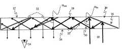
- FIG. 2illustrates a sectional view of an LOE according to the present invention.
- the first reflecting surface 16is illuminated by a collimated display 18 emanating from a light source (not shown) located behind the device.
- the reflecting surface 16reflects the incident light from the source such that the light is trapped inside a planar substrate 20 by total internal reflection. After several reflections off the surfaces of the substrate, the trapped light waves reach an array of selectively reflecting surfaces 22 , which couple the light out of the substrate into the eye 24 of a viewer.
- the input surface of the LOEwill be defined as the surface through which the input light waves enter the LOE and the output surface of the LOE will be defined as the surface through which the trapped light waves exit the LOE.
- both the input and the output surfacescoincide with the lower surface 26 .
- the input and the image light wavescould be located on opposite sides of the substrate. Assuming that the central light wave of the source is coupled out of the substrate 20 in a direction normal to the substrate surface 26 , the reflecting surfaces 22 are flat, and the off-axis angle of the coupled light wave inside the substrate 20 is ⁇ in , then the angle ⁇ sur2 between the reflecting surfaces and the normal to the substrate plane is:
- the trapped raysarrive at the reflecting surfaces from two distinct directions 28 , 30 .
- the trapped raysarrive at the reflecting surface from one of these directions 28 after an even number of reflections from the substrate surfaces 26 and 27 , wherein the incident angle ⁇ ref between the trapped ray and the normal to the reflecting surface is:
- each rayfirst arrives at the surface from the direction 30 , wherein some of the rays impinge on the surface again, from direction 28 .
- FIGS. 3A and 3Billustrate the desired reflectance behavior of selectively reflecting surfaces. While the ray 32 ( FIG. 3A ), having an off-axis angle of ⁇ ref ⁇ 25°, is partially reflected and is coupled out of the substrate 34 , the ray 36 ( FIG. 3B ), which arrives at an off-axis angle of ⁇ ′ ref ⁇ 75° to the reflecting surface (which is equivalent to ⁇ ′ ref ⁇ 105°), is transmitted through the reflecting surface 34 without any notable reflection.
- FIG. 4is a detailed sectional view of an array of selectively reflective surfaces which couple light trapped inside the substrate out and into the eye of a viewer.
- An alternative solutionutilizes anisotropic reflecting surfaces, that is, optical surfaces having a major axis parallel to the surface plane wherein the reflection and transmission properties of the surface depend strongly in the orientation of the polarization of the incident light in relation to the major axis of the surface.
- the desired discrimination between the two incident directionscan be achieved by exploiting the fact that the undesired direction meets the surface after the ray has transferred the surface in the desired direction.
- FIG. 5illustrates an example of an anisotropic partially reflecting surface 40 having a major axis 42 .
- An unpolarized light wave 44impinges on the surface.
- the partially reflecting surfacereflects the component of the light 46 with its electrical field vector parallel to the major axis 42 and transmits the component of the light 48 with its electrical field vector perpendicular to the major axis 42 .
- a possible candidate for the required anisotropic partially reflecting elementcan be a wire grid polarizing beamsplitter 50 , generally in the form of an array of thin parallel conductors supported by a transparent substrate.
- the key factor that determines the performance of a wire grid polarizing beamsplitter 50is the relationship between the center-to-center spacing, or period, of the parallel grid elements and the wavelength of the incident radiation. When the grid spacing or period is much shorter than the wavelength, the grid functions as a polarizing beamsplitter 50 that reflects electromagnetic radiation polarized parallel to the grid elements, and transmits radiation of the orthogonal polarization.
- the major axis of a wire grid polarizing beamsplitter 50is defined as parallel to the array of conductors.
- the wire grid polarizing beamsplittershould be used to transmit the p-polarization and reflect the s-polarization, as illustrated in FIG. 5 . It is, however, also possible to use the beamsplitter in the orthogonal orientation, illustrated in FIG. 6 , i.e., the main axis 52 of the polarizing beamsplitter 50 is oriented parallel to the propagation direction of the incident beam 44 .
- the polarizing beamsplitter 50Since now the major axis of the polarizing beamsplitter 50 is parallel to the electric field of the p-polarized light, the polarizing beamsplitter 50 reflects the component of the p-polarized light 56 with its electrical field vector parallel to the major axis 52 and transmits the component of the s-polarized light 58 with its electrical field vector perpendicular to the major axis 52 .
- the geometry illustrated in FIG. 6has reduced efficiency and contrast compared to the one described in FIG. 5 . However, for some applications this geometry can also be useful.
- FIG. 7illustrates an example of an LOE, exploiting wire grid polarizing beamsplitters as partially reflecting surfaces according to the present invention.
- the first reflecting surface 16is illuminated by an unpolarized collimated display 18 emanating from a light source (not shown) located behind the device.
- the reflecting surface 16reflects the incident light from the source such that the light is trapped inside the planar substrate 20 by total internal reflection. After several reflections off the surfaces of the substrate, the trapped light waves reach the first partially reflecting surface 22 a , the major axis of which is oriented to reflect the s-polarized component 60 of the trapped light wave 18 .
- the p-polarized component 62is transmitted and then reflected by the second reflecting surface 22 b , the major axis of which is oriented to reflect p-polarized light waves. Both the s-polarized 60 and the p-polarized 62 light waves are coupled out of the substrate into the eye of a viewer. Naturally, for this configuration, the polarization components of the input beam should be balanced. Hence, care must be taken to prevent birefringent effects from the collimating lens as well as in the substrate 20 itself.
- FIG. 8is a detailed sectional view of the selectively reflective surface 22 , which couples light trapped inside the substrate, out and into the eye of a viewer.
- the coupled ray 18passes through a reflecting surface 22 three times.
- the s-polarized component 72is reflected and coupled out of the substrate.
- the transmitted p-polarized component 74is reflected off the upper surface 27 and then meets surface 22 again at the points 76 and 78 , in between which it is again reflected off the opposite outer surface 27 .
- the incident lightis p-polarized, while the orientation of surface 22 is set to reflect s-polarized light and to transmit p-polarized light.
- the reflections at these pointscan be negligible, as required above, in relation to FIG. 2 , in order to prevent undesired reflections and ghost images.
- thiscan be valid not only for the example illustrated in FIGS. 7 and 8 but also in more general cases, wherein more than two partially reflecting surfaces are utilized to project the image into the eyes of a viewer.
- the raythen intersects the same selectively reflecting surface at point 84 at an incident angle of 75° without noticeable reflection, and then intersects again at point 86 at an incident angle of 25°, where another portion of the energy of the ray is coupled out of the substrate.
- the ray 88 shown in FIG. 9Bexperiences only one reflection from the same surface. Further multiple reflections occur at smaller incident angles. It is difficult to fully compensate for such differences in multiple-intersection effects. Nevertheless, in practice, the human eye tolerates significant variations in brightness, which remain unnoticed.
- the eyeintegrates all of the light which emerges from a single viewing angle and focuses it onto one point on the retina, and since the response curve of the eye is logarithmic, small variations, if any, in the brightness of the display will not be noticeable. Therefore, even for moderate levels of illumination uniformity within the display, the human eye experiences a high-quality image.
- the required moderate uniformitycan be readily achieved with an LOE.
- displays located at a distance from the eyehowever, like head-up displays, the non-uniformity due to the multiple intersection effects cannot be tolerated. For these cases, a more systematic method to overcome the non-uniformity is required.
- FIG. 10illustrates a detailed sectional view of the selectively reflective surface 22 , which couples light trapped inside the substrate out and into the eye of a viewer.
- the ray 18 ais reflected off the upper surface 27 , next to the line 100 , which is the intersection of the reflecting surface 22 with the upper surface 26 . Since this ray does not impinge on the reflecting surface 22 , its polarization remains the same and its first incidence at surface 22 is at the point 102 , after double reflection from both external surfaces. At this point, the light wave is partially reflected and the ray 104 is coupled out of the substrate.
- the inactive portions of the selectively reflecting surfaces 22do not contribute to the coupling of the trapped light waves out of the substrate, their impact on the optical performance of the LOE can be only negative. That is, if there is no overlapping between the reflecting surfaces then there will be inactive optical portions in the output aperture of the system and “holes” will exist in the image.
- the inactive portions of the reflecting surfacesare certainly active with respect to the light waves from the external scene.
- the major axis orientation of two adjacent surfacescannot be identical; otherwise the entire second surface will be inactive.
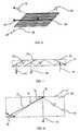
- FIG. 11illustrates a method of overcoming this problem. Only the active portions of the partially reflecting surfaces are embedded inside the substrate, that is, the reflecting surfaces 22 no longer intersect with the lower major surface 26 , namely, terminate short of the surface 26 . Since the ends of the reflecting surfaces are adjacent to one another over the length of the LOE, there will be no holes in the projected image, and since there is no overlap between the surfaces there will be no holes in the external view. There are several ways to achieve this, one of which is to attach a blank plate 20 , preferably by optical cementing, to the active area of the substrate. In order to utilize only the active areas of the reflective surfaces 22 , in the correct manner, it is important to calculate the actual active area of each reflective surface.
- the active aperture, D nof the reflective surface 22 n in the place of the external surface, as a function of the coupled-in angle ⁇ in , is.
- FIG. 14a sectional view of a compact LOE display system based on the proposed configuration, illustrates this effect.
- a single plane light wave 112representing a particular viewing angle 114 , illuminates only part of the overall array of partially reflecting surfaces 22 .
- a nominal viewing angleis defined, and the required active area of the reflecting surface is calculated according to this angle.
- the exact, detailed design of the active area of the various partially reflective surfacesis performed as follows: For each particular surface, a ray is plotted (taking refraction, due to Snell's Law, into consideration) from the left edge of the surface to the center of the designated eye pupil 24 . The calculated direction is set as the nominal incident direction and the particular active area is calculated according to that direction.
- the exact values of the reflecting surfaces active areascan be used to determine the various distances between the reflecting surfaces 22 .
- a larger active areadictates a larger inter-surface distance.
- more accurate calculationsmust be performed in order to determine exact distances between any two adjacent reflecting surfaces.
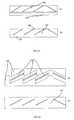
- FIG. 15illustrates this issue.
- the projection of each surfaceis adjacent to its neighbor so as to avoid either overlapping or gaps between the reflecting surfaces. This is true, however, for the central viewing angle only.
- the right-most reflecting surfacethere are gaps 116 between the right-most surfaces, whereas there is overlapping 118 between the left-most surfaces. Controlling the distances between each pair of adjacent surfaces 22 can solve this problem. That is, the inter-surface distances will be smaller for the right surfaces and larger for the left surfaces. As a result, this effect partially compensates the divergence in surface distances, which is described above with regards to active area sizes.
- FIG. 16illustrates the required distance between two adjacent surfaces as a function of the field angle for the same parameters as set above in reference to FIG. 13 .
- the detailed design of the distance between two adjacent reflecting surfacesis performed as follows: For each particular surface, a ray is plotted (taking refraction, due to Snell's Law, into consideration) from the left edge of the surface to the center of the designated eye pupil 24 . The calculated direction is set as the nominal incident direction and the particular distance is calculated according to that direction.
- FIG. 17illustrates an LOE 20 with reflecting surfaces 22 which have different active apertures and different distances between the partially reflecting surfaces and the lower major surface 26 of the substrate 20 .
- a wedged substratethat is, wherein the two major surfaces are not parallel
- a complementary blank wedged plateis attached to the substrate, preferably by optical cementing, in such a way that the combined structure forms a complete rectangular parallelepiped. That is, the two outer major surfaces of the final LOE are parallel to each other.
- the geometry presented in FIG. 17is required for displays located at a distance from the eye only, like head-up displays, wherein the non-uniformity due to the multiple intersection effects cannot be tolerated, for systems with a large number of facets, or when the exact dimension of the overall output aperture is critical.
- a simpler geometrydescribed in reference to FIG.
- the distance between the reflecting surfaces 22 and the lower surface 26may be sufficient.
- the calculated active areas of the surfaces 22 a , 22 b and 22 care 6.53 mm, 5.96 mm and 5.45 mm respectively, and the distances between these surfaces and the lower major surface 26 are 0.81 mm, 1.09 mm and 1.34 mm respectively.
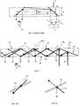
- FIG. 18which illustrates one method for coupling-in, presents a sectional view of the reflective surface 16 , which is embedded inside the substrate 20 and couples light 18 from a display source (not shown) and traps it inside the substrate 20 by total internal reflection. As explained above, so as to avoid an image with gaps or stripes, it is essential that the trapped light covers the entire area of the LOE major surfaces.
- the points on the boundary line 120 between the edge of the reflective surface 16 and the upper surface 27 of the substrate 20should be illuminated for a single light wave by the two extreme rays that enter the substrate from two different locations; a ray 18 a , which illuminates the boundary line 120 directly, and another ray 18 b , which is first reflected by the reflecting surface 16 and then by the lower surface 26 of the substrate, before illuminating the boundary line.
- a ray 18 awhich illuminates the boundary line 120 directly
- another ray 18 bwhich is first reflected by the reflecting surface 16 and then by the lower surface 26 of the substrate, before illuminating the boundary line.
- the reflecting surface 16intersects with the upper surface 27 , which is opposite the input surface 26 .
- Input light wavescan, however, be coupled into the substrate by other optical means as well, including (but not limited to) folding prisms, diffraction gratings, and other solutions.
- folding prismsdiffraction gratings
- other solutionsit is essential that one edge of the coupling-in element will intersect with one of the major surfaces in order to create a definite boundary line at which the two extreme rays of the input light waves can coincide.
- the added blank plate at one of the major surfaces of the LOB caremust be taken that the added blank plate will not block the intersection between the coupling-in element and the major surface opposite to the input surface bf the LOB.
- the preferred surface to add the blank plate atis the input surface.
- Another important issue that must be verified in order to obtain a smooth imageis the active aperture of the couple-in element. As illustrated in FIG. 18 , in order to ensure that the two extreme rays 18 a and 18 b , of all of the light waves in the FOV of the system, indeed coincide, then the active aperture, D in , of the surface 16 in the plane of the external surface 26 has to be at least:
- FIG. 19illustrates an optical system wherein the input light waves 18 enter the LOE through the upper surface 27 . Therefore, as explained above in reference to FIG. 18 , surface 16 must intersect with the lower surface 26 . However, adding a blank plate over the entire aperture of the lower surface 26 in this configuration would eradicate the required intersection between surfaces 16 and 26 . Hence, the blank plate must be added at the opposite surface 27 or an alternative solution must be found.
- FIG. 20illustrates an LOE wherein a blank plate 20 ′ is added at the upper surface, assuming an on-axis input light wave and the same parameters as defined above in reference to FIG. 2 .
- the first potential intersection of the coupled ray 18 with the first reflecting surface 22 ais avoided as a result of the blank plate 122 .
- the rayis reflected from the upper surface 27 and then intersects the same reflecting surface 22 a at point 124 at an incident angle of 75° wherein noticeable reflection is required. It then intersects the reflecting surface again at point 126 at an incident angle of 25°, where a portion of the energy of the ray must be coupled out of the substrate.
- the reflectancedepends on the incident angle of the incoming ray only.
- the reflectance of the first incidence 124being at a large angle, is negligible, wherein the reflectance of the second incidence, being at the designated angle of 25°, is as designed. Therefore, the performance in this situation is as required.
- the reflectancedoes not depend on the incident angle but rather on the order of the various incidences. That is, at the first incidence the ray is partially reflected wherein at the following incidences with the same reflecting surface the reflectance is negligible.
- FIG. 21illustrates a method, applicable to each of the approaches described above, in reference to FIGS. 13 and 17 , of attaching at step (a) a blank plate 132 to one of the major surfaces of the substrate 130 , preferably using optical cement, so as to yield at (b) an LOE 134 with the appropriate active apertures for all of the reflecting surfaces.
- a blank plate 132to one of the major surfaces of the substrate 130 , preferably using optical cement, so as to yield at (b) an LOE 134 with the appropriate active apertures for all of the reflecting surfaces.
- both the substrate 130 and the blank plate 132have a wedge structure. In that case it is usually required that the two external major surfaces, 136 and 138 , be parallel to each other in such a way that the combined structure from a complete rectangular parallelepiped.
- FIG. 22illustrates another method of fabricating the array of partially reflecting surfaces at step (a).
- Two similar, tooth-shaped transparent forms 140are fabricated by injection-molding or casting.
- the required reflecting surfaces 142(either anisotropic or coated thin-film) are inserted in the appropriate places between the forms 140 and the two forms are then glued together at (b) to create the required LOE 144 .
- LOEs based on anisotropic reflecting surfacesto remove or thin down the upper blank portion of the LOE, in order to enable the reflecting surfaces to intersect the upper surface of the LOE.
- FIG. 23illustrates yet another version of the method described in FIG. 22 for fabricating the array of partially reflecting surfaces. Instead of inserting the reflecting surfaces 142 at step (a), the surfaces are applied to a very thin and flexible polymer sheet 146 . The sheet 146 is inserted in step (b) between forms 140 , which are then cemented together to create the requested LOE.
- FIGS. 21 to 23are not applicable to an LOE based on anisotropic reflecting surfaces with the geometry illustrated in FIG. 19 wherein the input surface 27 is opposite to the output surface 26 .
- a possible way to fabricate the required LOEis illustrated in FIG. 24 .
- two different partswhich include the coupling-out 148 and the couple-in 150 portions, are fabricated separately.
- the two portionsare attached together at their peripheral sides to materialize the complete LOE form 20 .
Landscapes
- Physics & Mathematics (AREA)
- General Physics & Mathematics (AREA)
- Optics & Photonics (AREA)
- Devices For Indicating Variable Information By Combining Individual Elements (AREA)
Abstract
Description
wherein T is the substrate thickness;
FOVmax≈2v αmax, (2)
wherein v is the refractive index of the substrate.
Typically the refractive index values lie in the range of 1.5-1.6.
wherein, αsur, is the angle between the reflecting surface and the normal to the substrate plane, and Reye, is the distance between the eye of the viewer and the substrate (typically, about 30-40 mm).
β′ref=105°; αin=50°; α′in=130°; αsur2=25°. (7)
Claims (26)
Applications Claiming Priority (5)
| Application Number | Priority Date | Filing Date | Title |
|---|---|---|---|
| IL166799 | 2005-02-10 | ||
| IL166799AIL166799A (en) | 2005-02-10 | 2005-02-10 | Substrate-guided optical device utilizing beam splitters |
| IL173451 | 2006-01-31 | ||
| IL173451AIL173451A (en) | 2006-01-31 | 2006-01-31 | Substrate-guided optical device utilizing thin transparent layer |
| PCT/IL2006/000157WO2006085309A1 (en) | 2005-02-10 | 2006-02-08 | Substrate-guided optical device utilizing thin transparent layer |
Publications (2)
| Publication Number | Publication Date |
|---|---|
| US20090122414A1 US20090122414A1 (en) | 2009-05-14 |
| US7724443B2true US7724443B2 (en) | 2010-05-25 |
Family
ID=36226892
Family Applications (1)
| Application Number | Title | Priority Date | Filing Date |
|---|---|---|---|
| US11/815,547Active2027-02-10US7724443B2 (en) | 2005-02-10 | 2006-02-08 | Substrate-guided optical device utilizing thin transparent layer |
Country Status (3)
| Country | Link |
|---|---|
| US (1) | US7724443B2 (en) |
| EP (1) | EP1849033B1 (en) |
| WO (1) | WO2006085309A1 (en) |
Cited By (190)
| Publication number | Priority date | Publication date | Assignee | Title |
|---|---|---|---|---|
| US20080278812A1 (en)* | 2005-11-08 | 2008-11-13 | Lumus Ltd. | Polarizing Optical System |
| US8189263B1 (en) | 2011-04-01 | 2012-05-29 | Google Inc. | Image waveguide with mirror arrays |
| US8294994B1 (en) | 2011-08-12 | 2012-10-23 | Google Inc. | Image waveguide having non-parallel surfaces |
| US8467133B2 (en) | 2010-02-28 | 2013-06-18 | Osterhout Group, Inc. | See-through display with an optical assembly including a wedge-shaped illumination system |
| US8472119B1 (en) | 2011-08-12 | 2013-06-25 | Google Inc. | Image waveguide having a bend |
| US8471967B2 (en) | 2011-07-15 | 2013-06-25 | Google Inc. | Eyepiece for near-to-eye display with multi-reflectors |
| US8472120B2 (en) | 2010-02-28 | 2013-06-25 | Osterhout Group, Inc. | See-through near-eye display glasses with a small scale image source |
| US8477425B2 (en) | 2010-02-28 | 2013-07-02 | Osterhout Group, Inc. | See-through near-eye display glasses including a partially reflective, partially transmitting optical element |
| US8482859B2 (en) | 2010-02-28 | 2013-07-09 | Osterhout Group, Inc. | See-through near-eye display glasses wherein image light is transmitted to and reflected from an optically flat film |
| US8488246B2 (en) | 2010-02-28 | 2013-07-16 | Osterhout Group, Inc. | See-through near-eye display glasses including a curved polarizing film in the image source, a partially reflective, partially transmitting optical element and an optically flat film |
| US8503087B1 (en) | 2010-11-02 | 2013-08-06 | Google Inc. | Structured optical surface |
| US8508851B2 (en) | 2011-07-20 | 2013-08-13 | Google Inc. | Compact see-through display system |
| US8576143B1 (en) | 2010-12-20 | 2013-11-05 | Google Inc. | Head mounted display with deformation sensors |
| US8582209B1 (en) | 2010-11-03 | 2013-11-12 | Google Inc. | Curved near-to-eye display |
| US8634139B1 (en) | 2011-09-30 | 2014-01-21 | Rockwell Collins, Inc. | System for and method of catadioptric collimation in a compact head up display (HUD) |
| US8666212B1 (en) | 2011-04-28 | 2014-03-04 | Google Inc. | Head mounted display using a fused fiber bundle |
| US8670000B2 (en) | 2011-09-12 | 2014-03-11 | Google Inc. | Optical display system and method with virtual image contrast control |
| US8699842B2 (en) | 2011-05-27 | 2014-04-15 | Google Inc. | Image relay waveguide and method of producing same |
| US8743464B1 (en) | 2010-11-03 | 2014-06-03 | Google Inc. | Waveguide with embedded mirrors |
| US8749886B2 (en) | 2012-03-21 | 2014-06-10 | Google Inc. | Wide-angle wide band polarizing beam splitter |
| US8749890B1 (en) | 2011-09-30 | 2014-06-10 | Rockwell Collins, Inc. | Compact head up display (HUD) for cockpits with constrained space envelopes |
| US8760762B1 (en) | 2011-08-12 | 2014-06-24 | Google Inc. | Image waveguide utilizing two mirrored or polarized surfaces |
| US8760765B2 (en) | 2012-03-19 | 2014-06-24 | Google Inc. | Optical beam tilt for offset head mounted display |
| US8767305B2 (en) | 2011-08-02 | 2014-07-01 | Google Inc. | Method and apparatus for a near-to-eye display |
| US8767306B1 (en) | 2011-09-22 | 2014-07-01 | Google Inc. | Display system |
| US8773599B2 (en) | 2011-10-24 | 2014-07-08 | Google Inc. | Near-to-eye display with diffraction grating that bends and focuses light |
| US8786686B1 (en) | 2011-09-16 | 2014-07-22 | Google Inc. | Head mounted display eyepiece with integrated depth sensing |
| US8814691B2 (en) | 2010-02-28 | 2014-08-26 | Microsoft Corporation | System and method for social networking gaming with an augmented reality |
| US8817379B2 (en) | 2011-07-12 | 2014-08-26 | Google Inc. | Whole image scanning mirror display system |
| US8823740B1 (en) | 2011-08-15 | 2014-09-02 | Google Inc. | Display system |
| US8830588B1 (en) | 2012-03-28 | 2014-09-09 | Rockwell Collins, Inc. | Reflector and cover glass for substrate guided HUD |
| US8848289B2 (en) | 2012-03-15 | 2014-09-30 | Google Inc. | Near-to-eye display with diffractive lens |
| US8867139B2 (en) | 2012-11-30 | 2014-10-21 | Google Inc. | Dual axis internal optical beam tilt for eyepiece of an HMD |
| US8867131B1 (en) | 2012-03-06 | 2014-10-21 | Google Inc. | Hybrid polarizing beam splitter |
| US8873148B1 (en) | 2011-12-12 | 2014-10-28 | Google Inc. | Eyepiece having total internal reflection based light folding |
| US8903207B1 (en) | 2011-09-30 | 2014-12-02 | Rockwell Collins, Inc. | System for and method of extending vertical field of view in head up display utilizing a waveguide combiner |
| US8937772B1 (en) | 2011-09-30 | 2015-01-20 | Rockwell Collins, Inc. | System for and method of stowing HUD combiners |
| US8941560B2 (en) | 2011-09-21 | 2015-01-27 | Google Inc. | Wearable computer with superimposed controls and instructions for external device |
| CN104503087A (en)* | 2015-01-25 | 2015-04-08 | 上海理湃光晶技术有限公司 | Polarization light guide planar waveguide optical display device |
| US9013793B2 (en) | 2011-09-21 | 2015-04-21 | Google Inc. | Lightweight eyepiece for head mounted display |
| US9069115B2 (en) | 2013-04-25 | 2015-06-30 | Google Inc. | Edge configurations for reducing artifacts in eyepieces |
| US9087471B2 (en) | 2011-11-04 | 2015-07-21 | Google Inc. | Adaptive brightness control of head mounted display |
| US9091851B2 (en) | 2010-02-28 | 2015-07-28 | Microsoft Technology Licensing, Llc | Light control in head mounted displays |
| US9097890B2 (en) | 2010-02-28 | 2015-08-04 | Microsoft Technology Licensing, Llc | Grating in a light transmissive illumination system for see-through near-eye display glasses |
| US9097891B2 (en) | 2010-02-28 | 2015-08-04 | Microsoft Technology Licensing, Llc | See-through near-eye display glasses including an auto-brightness control for the display brightness based on the brightness in the environment |
| US9116337B1 (en) | 2012-03-21 | 2015-08-25 | Google Inc. | Increasing effective eyebox size of an HMD |
| US9128285B2 (en)* | 2013-04-30 | 2015-09-08 | Google Inc. | Head-mounted display including integrated projector |
| US9129295B2 (en) | 2010-02-28 | 2015-09-08 | Microsoft Technology Licensing, Llc | See-through near-eye display glasses with a fast response photochromic film system for quick transition from dark to clear |
| US9128281B2 (en) | 2010-09-14 | 2015-09-08 | Microsoft Technology Licensing, Llc | Eyepiece with uniformly illuminated reflective display |
| US9134534B2 (en) | 2010-02-28 | 2015-09-15 | Microsoft Technology Licensing, Llc | See-through near-eye display glasses including a modular image source |
| US9182596B2 (en) | 2010-02-28 | 2015-11-10 | Microsoft Technology Licensing, Llc | See-through near-eye display glasses with the optical assembly including absorptive polarizers or anti-reflective coatings to reduce stray light |
| US9194995B2 (en) | 2011-12-07 | 2015-11-24 | Google Inc. | Compact illumination module for head mounted display |
| US9223134B2 (en) | 2010-02-28 | 2015-12-29 | Microsoft Technology Licensing, Llc | Optical imperfections in a light transmissive illumination system for see-through near-eye display glasses |
| US9229227B2 (en) | 2010-02-28 | 2016-01-05 | Microsoft Technology Licensing, Llc | See-through near-eye display glasses with a light transmissive wedge shaped illumination system |
| US9239415B2 (en) | 2012-03-08 | 2016-01-19 | Google Inc. | Near-to-eye display with an integrated out-looking camera |
| US9244281B1 (en) | 2013-09-26 | 2016-01-26 | Rockwell Collins, Inc. | Display system and method using a detached combiner |
| US9244280B1 (en) | 2014-03-25 | 2016-01-26 | Rockwell Collins, Inc. | Near eye display system and method for display enhancement or redundancy |
| US9274339B1 (en) | 2010-02-04 | 2016-03-01 | Rockwell Collins, Inc. | Worn display system and method without requiring real time tracking for boresight precision |
| US9285589B2 (en) | 2010-02-28 | 2016-03-15 | Microsoft Technology Licensing, Llc | AR glasses with event and sensor triggered control of AR eyepiece applications |
| US9285591B1 (en) | 2014-08-29 | 2016-03-15 | Google Inc. | Compact architecture for near-to-eye display system |
| US9291822B2 (en)* | 2010-10-21 | 2016-03-22 | Seiko Epson Corporation | Light guide plate and virtual image display device equipped with the same |
| US9329388B1 (en) | 2011-04-28 | 2016-05-03 | Google Inc. | Heads-up display for a large transparent substrate |
| US9341843B2 (en) | 2010-02-28 | 2016-05-17 | Microsoft Technology Licensing, Llc | See-through near-eye display glasses with a small scale image source |
| US9341846B2 (en) | 2012-04-25 | 2016-05-17 | Rockwell Collins Inc. | Holographic wide angle display |
| US9366864B1 (en) | 2011-09-30 | 2016-06-14 | Rockwell Collins, Inc. | System for and method of displaying information without need for a combiner alignment detector |
| US9366862B2 (en) | 2010-02-28 | 2016-06-14 | Microsoft Technology Licensing, Llc | System and method for delivering content to a group of see-through near eye display eyepieces |
| US9366869B2 (en) | 2014-11-10 | 2016-06-14 | Google Inc. | Thin curved eyepiece for see-through head wearable display |
| US9389422B1 (en) | 2013-12-23 | 2016-07-12 | Google Inc. | Eyepiece for head wearable display using partial and total internal reflections |
| US9395544B2 (en) | 2014-03-13 | 2016-07-19 | Google Inc. | Eyepiece with switchable reflector for head wearable display |
| US9459455B2 (en) | 2013-12-19 | 2016-10-04 | Google Inc. | See-through eyepiece for head wearable display |
| US9507150B1 (en) | 2011-09-30 | 2016-11-29 | Rockwell Collins, Inc. | Head up display (HUD) using a bent waveguide assembly |
| US9519092B1 (en) | 2012-03-21 | 2016-12-13 | Google Inc. | Display method |
| US9519089B1 (en) | 2014-01-30 | 2016-12-13 | Rockwell Collins, Inc. | High performance volume phase gratings |
| US9523852B1 (en) | 2012-03-28 | 2016-12-20 | Rockwell Collins, Inc. | Micro collimator system and method for a head up display (HUD) |
| US20160377868A1 (en)* | 2014-03-18 | 2016-12-29 | 3M Innovative Properties Company | Low profile image combiner for near-eye displays |
| US9581814B2 (en) | 2012-01-20 | 2017-02-28 | Microsoft Technology Licensing, Llc | Transparent display for mobile device |
| US9658453B1 (en) | 2013-04-29 | 2017-05-23 | Google Inc. | Head-mounted display including diffractive combiner to integrate a display and a sensor |
| US9674413B1 (en) | 2013-04-17 | 2017-06-06 | Rockwell Collins, Inc. | Vision system and method having improved performance and solar mitigation |
| US9715067B1 (en) | 2011-09-30 | 2017-07-25 | Rockwell Collins, Inc. | Ultra-compact HUD utilizing waveguide pupil expander with surface relief gratings in high refractive index materials |
| US9715110B1 (en) | 2014-09-25 | 2017-07-25 | Rockwell Collins, Inc. | Automotive head up display (HUD) |
| US9729767B2 (en) | 2013-03-22 | 2017-08-08 | Seiko Epson Corporation | Infrared video display eyewear |
| US9759917B2 (en) | 2010-02-28 | 2017-09-12 | Microsoft Technology Licensing, Llc | AR glasses with event and sensor triggered AR eyepiece interface to external devices |
| US9897811B2 (en) | 2016-04-07 | 2018-02-20 | Google Llc | Curved eyepiece with color correction for head wearable display |
| US9915823B1 (en) | 2014-05-06 | 2018-03-13 | Google Llc | Lightguide optical combiner for head wearable display |
| US9933684B2 (en) | 2012-11-16 | 2018-04-03 | Rockwell Collins, Inc. | Transparent waveguide display providing upper and lower fields of view having a specific light output aperture configuration |
| US9946074B2 (en) | 2016-04-07 | 2018-04-17 | Google Llc | See-through curved eyepiece with patterned optical combiner |
| US10048499B2 (en) | 2005-11-08 | 2018-08-14 | Lumus Ltd. | Polarizing optical system |
| US10089516B2 (en) | 2013-07-31 | 2018-10-02 | Digilens, Inc. | Method and apparatus for contact image sensing |
| US10088675B1 (en) | 2015-05-18 | 2018-10-02 | Rockwell Collins, Inc. | Turning light pipe for a pupil expansion system and method |
| EP3385774A1 (en) | 2017-04-06 | 2018-10-10 | Lumus Ltd. | Light-guide optical element and method of its manufacture |
| US10108010B2 (en) | 2015-06-29 | 2018-10-23 | Rockwell Collins, Inc. | System for and method of integrating head up displays and head down displays |
| US10120194B2 (en) | 2016-01-22 | 2018-11-06 | Corning Incorporated | Wide field personal display |
| US10126552B2 (en) | 2015-05-18 | 2018-11-13 | Rockwell Collins, Inc. | Micro collimator system and method for a head up display (HUD) |
| US10145533B2 (en) | 2005-11-11 | 2018-12-04 | Digilens, Inc. | Compact holographic illumination device |
| US10146054B2 (en) | 2015-07-06 | 2018-12-04 | Google Llc | Adding prescriptive correction to eyepieces for see-through head wearable displays |
| US10156681B2 (en) | 2015-02-12 | 2018-12-18 | Digilens Inc. | Waveguide grating device |
| US10162180B2 (en) | 2015-06-04 | 2018-12-25 | Google Llc | Efficient thin curved eyepiece for see-through head wearable display |
| US10180572B2 (en) | 2010-02-28 | 2019-01-15 | Microsoft Technology Licensing, Llc | AR glasses with event and user action control of external applications |
| US10185154B2 (en) | 2011-04-07 | 2019-01-22 | Digilens, Inc. | Laser despeckler based on angular diversity |
| US10209517B2 (en) | 2013-05-20 | 2019-02-19 | Digilens, Inc. | Holographic waveguide eye tracker |
| US10216061B2 (en) | 2012-01-06 | 2019-02-26 | Digilens, Inc. | Contact image sensor using switchable bragg gratings |
| US10234696B2 (en) | 2007-07-26 | 2019-03-19 | Digilens, Inc. | Optical apparatus for recording a holographic device and method of recording |
| US10241330B2 (en) | 2014-09-19 | 2019-03-26 | Digilens, Inc. | Method and apparatus for generating input images for holographic waveguide displays |
| US20190094549A1 (en)* | 2017-09-28 | 2019-03-28 | Thalmic Labs Inc. | Systems, devices, and methods for waveguide-based eyebox expansion in wearable heads-up displays |
| US10247943B1 (en) | 2015-05-18 | 2019-04-02 | Rockwell Collins, Inc. | Head up display (HUD) using a light pipe |
| US10295824B2 (en) | 2017-01-26 | 2019-05-21 | Rockwell Collins, Inc. | Head up display with an angled light pipe |
| US10302945B2 (en) | 2015-08-12 | 2019-05-28 | Google Llc | Near-eye display with stacked lightguides |
| US10302835B2 (en) | 2017-02-22 | 2019-05-28 | Lumus Ltd. | Light guide optical assembly |
| US10330777B2 (en) | 2015-01-20 | 2019-06-25 | Digilens Inc. | Holographic waveguide lidar |
| US10338390B2 (en) | 2016-06-17 | 2019-07-02 | Google Llc | Method for fabricating a curved eyepiece |
| US10359736B2 (en) | 2014-08-08 | 2019-07-23 | Digilens Inc. | Method for holographic mastering and replication |
| US10409144B2 (en) | 2009-10-09 | 2019-09-10 | Digilens Inc. | Diffractive waveguide providing structured illumination for object detection |
| US10423222B2 (en) | 2014-09-26 | 2019-09-24 | Digilens Inc. | Holographic waveguide optical tracker |
| US10437051B2 (en) | 2012-05-11 | 2019-10-08 | Digilens Inc. | Apparatus for eye tracking |
| US10437031B2 (en) | 2016-11-08 | 2019-10-08 | Lumus Ltd. | Light-guide device with optical cutoff edge and corresponding production methods |
| US10437064B2 (en) | 2015-01-12 | 2019-10-08 | Digilens Inc. | Environmentally isolated waveguide display |
| US10459145B2 (en) | 2015-03-16 | 2019-10-29 | Digilens Inc. | Waveguide device incorporating a light pipe |
| US10481319B2 (en) | 2017-03-22 | 2019-11-19 | Lumus Ltd. | Overlapping facets |
| US10509241B1 (en) | 2009-09-30 | 2019-12-17 | Rockwell Collins, Inc. | Optical displays |
| US10520731B2 (en) | 2014-11-11 | 2019-12-31 | Lumus Ltd. | Compact head-mounted display system protected by a hyperfine structure |
| US10539787B2 (en) | 2010-02-28 | 2020-01-21 | Microsoft Technology Licensing, Llc | Head-worn adaptive display |
| US10545346B2 (en) | 2017-01-05 | 2020-01-28 | Digilens Inc. | Wearable heads up displays |
| US10551544B2 (en) | 2018-01-21 | 2020-02-04 | Lumus Ltd. | Light-guide optical element with multiple-axis internal aperture expansion |
| US10564417B2 (en) | 2016-10-09 | 2020-02-18 | Lumus Ltd. | Aperture multiplier using a rectangular waveguide |
| US10591756B2 (en) | 2015-03-31 | 2020-03-17 | Digilens Inc. | Method and apparatus for contact image sensing |
| US10598932B1 (en) | 2016-01-06 | 2020-03-24 | Rockwell Collins, Inc. | Head up display for integrating views of conformally mapped symbols and a fixed image source |
| US10642058B2 (en) | 2011-08-24 | 2020-05-05 | Digilens Inc. | Wearable data display |
| US10649214B2 (en) | 2005-02-10 | 2020-05-12 | Lumus Ltd. | Substrate-guide optical device |
| US10670876B2 (en) | 2011-08-24 | 2020-06-02 | Digilens Inc. | Waveguide laser illuminator incorporating a despeckler |
| US10678053B2 (en) | 2009-04-27 | 2020-06-09 | Digilens Inc. | Diffractive projection apparatus |
| US10690916B2 (en) | 2015-10-05 | 2020-06-23 | Digilens Inc. | Apparatus for providing waveguide displays with two-dimensional pupil expansion |
| US10690851B2 (en) | 2018-03-16 | 2020-06-23 | Digilens Inc. | Holographic waveguides incorporating birefringence control and methods for their fabrication |
| US10732407B1 (en) | 2014-01-10 | 2020-08-04 | Rockwell Collins, Inc. | Near eye head up display system and method with fixed combiner |
| US10732569B2 (en) | 2018-01-08 | 2020-08-04 | Digilens Inc. | Systems and methods for high-throughput recording of holographic gratings in waveguide cells |
| US10739512B2 (en)* | 2018-09-09 | 2020-08-11 | Lumus Ltd. | Optical systems including light-guide optical elements with two-dimensional expansion |
| US10795160B1 (en) | 2014-09-25 | 2020-10-06 | Rockwell Collins, Inc. | Systems for and methods of using fold gratings for dual axis expansion |
| US10809528B2 (en) | 2014-04-23 | 2020-10-20 | Lumus Ltd. | Compact head-mounted display system |
| US10860100B2 (en) | 2010-02-28 | 2020-12-08 | Microsoft Technology Licensing, Llc | AR glasses with predictive control of external device based on event input |
| US10859768B2 (en) | 2016-03-24 | 2020-12-08 | Digilens Inc. | Method and apparatus for providing a polarization selective holographic waveguide device |
| US10890707B2 (en) | 2016-04-11 | 2021-01-12 | Digilens Inc. | Holographic waveguide apparatus for structured light projection |
| US10914950B2 (en) | 2018-01-08 | 2021-02-09 | Digilens Inc. | Waveguide architectures and related methods of manufacturing |
| US10942430B2 (en) | 2017-10-16 | 2021-03-09 | Digilens Inc. | Systems and methods for multiplying the image resolution of a pixelated display |
| US10976551B2 (en) | 2017-08-30 | 2021-04-13 | Corning Incorporated | Wide field personal display device |
| US10983340B2 (en) | 2016-02-04 | 2021-04-20 | Digilens Inc. | Holographic waveguide optical tracker |
| US11092810B2 (en) | 2017-11-21 | 2021-08-17 | Lumus Ltd. | Optical aperture expansion arrangement for near-eye displays |
| US11204540B2 (en) | 2009-10-09 | 2021-12-21 | Digilens Inc. | Diffractive waveguide providing a retinal image |
| US11243434B2 (en) | 2017-07-19 | 2022-02-08 | Lumus Ltd. | LCOS illumination via LOE |
| US11300795B1 (en) | 2009-09-30 | 2022-04-12 | Digilens Inc. | Systems for and methods of using fold gratings coordinated with output couplers for dual axis expansion |
| US11307432B2 (en) | 2014-08-08 | 2022-04-19 | Digilens Inc. | Waveguide laser illuminator incorporating a Despeckler |
| US11320571B2 (en) | 2012-11-16 | 2022-05-03 | Rockwell Collins, Inc. | Transparent waveguide display providing upper and lower fields of view with uniform light extraction |
| US11366316B2 (en) | 2015-05-18 | 2022-06-21 | Rockwell Collins, Inc. | Head up display (HUD) using a light pipe |
| US11378732B2 (en) | 2019-03-12 | 2022-07-05 | DigLens Inc. | Holographic waveguide backlight and related methods of manufacturing |
| US11402801B2 (en) | 2018-07-25 | 2022-08-02 | Digilens Inc. | Systems and methods for fabricating a multilayer optical structure |
| US11415812B2 (en) | 2018-06-26 | 2022-08-16 | Lumus Ltd. | Compact collimating optical device and system |
| US11442222B2 (en) | 2019-08-29 | 2022-09-13 | Digilens Inc. | Evacuated gratings and methods of manufacturing |
| US11448816B2 (en) | 2019-01-24 | 2022-09-20 | Lumus Ltd. | Optical systems including light-guide optical elements with two-dimensional expansion |
| US11480788B2 (en) | 2015-01-12 | 2022-10-25 | Digilens Inc. | Light field displays incorporating holographic waveguides |
| US11513350B2 (en) | 2016-12-02 | 2022-11-29 | Digilens Inc. | Waveguide device with uniform output illumination |
| US11523092B2 (en) | 2019-12-08 | 2022-12-06 | Lumus Ltd. | Optical systems with compact image projector |
| US11543594B2 (en) | 2019-02-15 | 2023-01-03 | Digilens Inc. | Methods and apparatuses for providing a holographic waveguide display using integrated gratings |
| US11561335B2 (en) | 2019-12-05 | 2023-01-24 | Lumus Ltd. | Light-guide optical element employing complementary coated partial reflectors, and light-guide optical element having reduced light scattering |
| US11630260B2 (en) | 2020-05-24 | 2023-04-18 | Lumus Ltd. | Production method and corresponding structures of compound light-guide optical elements |
| US11681143B2 (en) | 2019-07-29 | 2023-06-20 | Digilens Inc. | Methods and apparatus for multiplying the image resolution and field-of-view of a pixelated display |
| US11726332B2 (en) | 2009-04-27 | 2023-08-15 | Digilens Inc. | Diffractive projection apparatus |
| US11747568B2 (en) | 2019-06-07 | 2023-09-05 | Digilens Inc. | Waveguides incorporating transmissive and reflective gratings and related methods of manufacturing |
| US11789264B2 (en) | 2021-07-04 | 2023-10-17 | Lumus Ltd. | Display with stacked light-guide elements providing different parts of field of view |
| US11796729B2 (en) | 2021-02-25 | 2023-10-24 | Lumus Ltd. | Optical aperture multipliers having a rectangular waveguide |
| US11822088B2 (en) | 2021-05-19 | 2023-11-21 | Lumus Ltd. | Active optical engine |
| US11860369B2 (en) | 2021-03-01 | 2024-01-02 | Lumus Ltd. | Optical system with compact coupling from a projector into a waveguide |
| US11885966B2 (en) | 2019-12-30 | 2024-01-30 | Lumus Ltd. | Optical systems including light-guide optical elements with two-dimensional expansion |
| US11886008B2 (en) | 2021-08-23 | 2024-01-30 | Lumus Ltd. | Methods of fabrication of compound light-guide optical elements having embedded coupling-in reflectors |
| US11914161B2 (en) | 2019-06-27 | 2024-02-27 | Lumus Ltd. | Apparatus and methods for eye tracking based on eye imaging via light-guide optical element |
| WO2024081698A1 (en)* | 2022-10-14 | 2024-04-18 | Google Llc | Waveguide with overlapping reflective facets |
| US12092914B2 (en) | 2018-01-08 | 2024-09-17 | Digilens Inc. | Systems and methods for manufacturing waveguide cells |
| US12124050B2 (en) | 2019-02-28 | 2024-10-22 | Lumus Ltd. | Compact collimated image projector |
| US12124037B2 (en) | 2020-05-24 | 2024-10-22 | Lumus Ltd. | Compound light-guide optical elements |
| US12135445B2 (en) | 2019-04-15 | 2024-11-05 | Lumus Ltd. | Method of fabricating a light-guide optical element |
| US12140790B2 (en) | 2019-07-18 | 2024-11-12 | Lumus Ltd. | Encapsulated light-guide optical element |
| US12140764B2 (en) | 2019-02-15 | 2024-11-12 | Digilens Inc. | Wide angle waveguide display |
| US12158612B2 (en) | 2021-03-05 | 2024-12-03 | Digilens Inc. | Evacuated periodic structures and methods of manufacturing |
| US12210153B2 (en) | 2019-01-14 | 2025-01-28 | Digilens Inc. | Holographic waveguide display with light control layer |
| US12210157B2 (en) | 2019-04-04 | 2025-01-28 | Lumus Ltd. | Air-gap free perpendicular near-eye display |
| US12222499B2 (en) | 2020-12-21 | 2025-02-11 | Digilens Inc. | Eye glow suppression in waveguide based displays |
| US12222508B2 (en) | 2020-08-26 | 2025-02-11 | Lumus Ltd. | Generation of color images using white light as source |
| US12306585B2 (en) | 2018-01-08 | 2025-05-20 | Digilens Inc. | Methods for fabricating optical waveguides |
| US12320983B1 (en) | 2022-08-18 | 2025-06-03 | Lumus Ltd. | Image projector with polarizing catadioptric collimator |
| US12372799B2 (en) | 2020-05-12 | 2025-07-29 | Lumus Ltd. | Rotatable lightpipe |
| US12399326B2 (en) | 2021-01-07 | 2025-08-26 | Digilens Inc. | Grating structures for color waveguides |
| US12397477B2 (en) | 2019-02-05 | 2025-08-26 | Digilens Inc. | Methods for compensating for optical surface nonuniformity |
| US12436400B2 (en) | 2020-08-23 | 2025-10-07 | Lumus Ltd. | Optical system |
Families Citing this family (59)
| Publication number | Priority date | Publication date | Assignee | Title |
|---|---|---|---|---|
| IL166799A (en) | 2005-02-10 | 2014-09-30 | Lumus Ltd | Substrate-guided optical device utilizing beam splitters |
| IL173715A0 (en) | 2006-02-14 | 2007-03-08 | Lumus Ltd | Substrate-guided imaging lens |
| IL177618A (en) | 2006-08-22 | 2015-02-26 | Lumus Ltd | Substrate- guided optical device |
| US8786519B2 (en) | 2008-03-04 | 2014-07-22 | Elbit Systems Ltd. | Head up display utilizing an LCD and a diffuser |
| US20100231498A1 (en)* | 2009-03-13 | 2010-09-16 | Microsoft Corporation | Image display via multiple light guide sections |
| FR2952728B1 (en)* | 2009-11-16 | 2012-06-15 | Sagem Defense Securite | DEVICE FOR VISUALIZING IMAGES SUPERIMPOSED TO AN IMAGE OF AN ENVIRONMENTAL SCENE, AND METHOD OF MANUFACTURING THE SAME |
| JP5408048B2 (en) | 2010-06-17 | 2014-02-05 | セイコーエプソン株式会社 | Light guide plate for virtual image display device and virtual image display device |
| IL219907A (en) | 2012-05-21 | 2017-08-31 | Lumus Ltd | Head-mounted display eyeball tracker integrated system |
| RU2579804C1 (en)* | 2014-09-16 | 2016-04-10 | Самсунг Электроникс Ко., Лтд. | Optical device for generating augmented reality images |
| DE102014113966A1 (en) | 2014-09-26 | 2016-03-31 | Carl Zeiss Jena Gmbh | Method for producing an optical element |
| CN104360484B (en) | 2014-12-02 | 2017-03-08 | 京东方科技集团股份有限公司 | A kind of light wave medium, glasses and its imaging method |
| IL236491B (en)* | 2014-12-25 | 2020-11-30 | Lumus Ltd | A method for fabricating substrate-guided optical device |
| IL236490B (en) | 2014-12-25 | 2021-10-31 | Lumus Ltd | Optical component on a conductive substrate |
| IL237337B (en) | 2015-02-19 | 2020-03-31 | Amitai Yaakov | Compact head-mounted display system having uniform image |
| IL244177B (en)* | 2016-02-18 | 2021-04-29 | Oorym Optics Ltd | Compact display system having uniform image |
| CN107305291A (en)* | 2016-04-22 | 2017-10-31 | 成都理想境界科技有限公司 | A kind of near-eye display system |
| JP6740366B2 (en) | 2016-05-18 | 2020-08-12 | ルーマス リミテッドLumus Ltd. | Head mount imaging device |
| CN107561698A (en)* | 2016-07-01 | 2018-01-09 | 成都理想境界科技有限公司 | A kind of near-eye display system, virtual reality device and augmented reality equipment |
| CN107561700A (en)* | 2016-07-01 | 2018-01-09 | 成都理想境界科技有限公司 | A kind of near-eye display system, virtual reality device and augmented reality equipment |
| DE212017000261U1 (en) | 2016-12-02 | 2019-08-05 | Lumus Ltd. | Optical system with compact collimator image projector |
| CN110431467A (en) | 2017-01-28 | 2019-11-08 | 鲁姆斯有限公司 | Augmented reality imaging system |
| US10859834B2 (en) | 2017-07-03 | 2020-12-08 | Holovisions | Space-efficient optical structures for wide field-of-view augmented reality (AR) eyewear |
| US10338400B2 (en) | 2017-07-03 | 2019-07-02 | Holovisions LLC | Augmented reality eyewear with VAPE or wear technology |
| US11513352B2 (en) | 2017-09-29 | 2022-11-29 | Lumus Ltd. | Augmented reality display |
| WO2019077614A1 (en) | 2017-10-22 | 2019-04-25 | Lumus Ltd. | ENHANCED REALITY DEVICE MOUNTED ON THE HEAD AND USING AN OPTICAL BENCH |
| CN111417883B (en) | 2017-12-03 | 2022-06-17 | 鲁姆斯有限公司 | Optical equipment alignment method |
| IL275013B (en) | 2017-12-03 | 2022-08-01 | Lumus Ltd | Method and device for testing an optics device |
| KR20200102408A (en) | 2018-01-02 | 2020-08-31 | 루머스 리미티드 | Augmented Reality Display with Active Alignment and Corresponding Method |
| MY203244A (en) | 2018-04-08 | 2024-06-19 | Lumus Ltd | Optical sample characterization |
| KR102752134B1 (en) | 2018-05-14 | 2025-01-08 | 루머스 리미티드 | Projector configuration with sub-optical aperture for near-eye display and corresponding optical system |
| IL278511B2 (en) | 2018-05-17 | 2025-01-01 | Lumus Ltd | Near-eye display having overlapping projector assemblies |
| IL259518B2 (en) | 2018-05-22 | 2023-04-01 | Lumus Ltd | Optical system and method for improvement of light field uniformity |
| MX2020012512A (en) | 2018-05-23 | 2021-02-16 | Lumus Ltd | Optical system including light-guide optical element with partially-reflective internal surfaces. |
| CN119595595A (en)* | 2018-06-21 | 2025-03-11 | 鲁姆斯有限公司 | Technique for measuring refractive index non-uniformity between plates of light-guiding optical element (LOE) |
| EP3824335B1 (en)* | 2018-07-16 | 2023-10-18 | Lumus Ltd. | Light-guide optical element employing polarized internal reflectors |
| CN112601993A (en) | 2018-08-26 | 2021-04-02 | 鲁姆斯有限公司 | Reflection suppression in near-eye displays |
| TWI827663B (en)* | 2018-09-06 | 2024-01-01 | 以色列商魯姆斯有限公司 | Near-eye display with laser diode illumination |
| US11947130B2 (en) | 2018-11-08 | 2024-04-02 | Lumus Ltd. | Optical devices and systems with dichroic beamsplitter color combiner |
| TWM642752U (en) | 2018-11-08 | 2023-06-21 | 以色列商魯姆斯有限公司 | Light-guide display with reflector |
| JP3226277U (en) | 2018-11-11 | 2020-05-14 | ルムス エルティーディー. | Near eye display with intermediate window |
| US10942320B2 (en)* | 2019-02-11 | 2021-03-09 | Facebook Technologies, Llc | Dispersion compensation for light coupling through slanted facet of optical waveguide |
| TWI800657B (en) | 2019-03-12 | 2023-05-01 | 以色列商魯姆斯有限公司 | Image projector |
| TWI845670B (en) | 2019-05-06 | 2024-06-21 | 以色列商魯姆斯有限公司 | Transparent lightguide for viewing a scene and a near-eye display |
| AU2020300121B2 (en) | 2019-07-04 | 2024-06-13 | Lumus Ltd. | Image waveguide with symmetric beam multiplication |
| US12111479B2 (en) | 2019-09-16 | 2024-10-08 | Lumus Ltd. | Image display system with beam multiplication |
| WO2021105982A1 (en) | 2019-11-25 | 2021-06-03 | Lumus Ltd. | Method of polishing a surface of a waveguide |
| IL270991B (en) | 2019-11-27 | 2020-07-30 | Lumus Ltd | Lightguide optical element for polarization scrambling |
| CN114787687B (en) | 2019-12-25 | 2024-07-30 | 鲁姆斯有限公司 | Systems and methods for eye tracking based on redirection of light from the eye using an optical arrangement associated with a light guide optical element |
| WO2021220267A1 (en) | 2020-04-30 | 2021-11-04 | Lumus Ltd. | Optical sample characterization |
| DE202021104723U1 (en) | 2020-09-11 | 2021-10-18 | Lumus Ltd. | Image projector coupled to an optical light guide element |
| CN116097151B (en) | 2020-11-09 | 2024-04-09 | 鲁姆斯有限公司 | Color Corrected Back Reflection in AR Systems |
| KR20240154688A (en) | 2020-11-18 | 2024-10-25 | 루머스 리미티드 | Optical-based validation of orientations of internal facets |
| US12032195B1 (en) | 2023-03-19 | 2024-07-09 | Lumus Ltd. | Optical aperture multipliers having a rectangular waveguide |
| CN117980798A (en) | 2021-07-04 | 2024-05-03 | 鲁姆斯有限公司 | Color-shifting optical system for near-eye displays |
| CN116413910B (en)* | 2021-12-30 | 2025-09-23 | 宏碁股份有限公司 | Augmented reality display devices |
| JP2025514899A (en) | 2022-05-04 | 2025-05-13 | ルムス エルティーディー. | Intermediate layer with adjusted color and gradient |
| KR20250043403A (en) | 2022-08-01 | 2025-03-28 | 루머스 리미티드 | A novel technique for the inspection of optical elements |
| WO2024154042A1 (en) | 2023-01-17 | 2024-07-25 | Lumus Ltd. | Characterizing optical system performance with a color camera |
| TWI855873B (en)* | 2023-09-22 | 2024-09-11 | 澤米科技股份有限公司 | Light-guide optical element and its manufacturing method |
Citations (7)
| Publication number | Priority date | Publication date | Assignee | Title |
|---|---|---|---|---|
| EP0399865A1 (en) | 1989-05-23 | 1990-11-28 | Thomson-Csf | Optical device for introduction of a collimated image into the field of view of an observer and helmet comprising such a device |
| EP0566004A2 (en) | 1992-04-07 | 1993-10-20 | Hughes Aircraft Company | Virtual image display having a high efficiency grid beamsplitter |
| WO2001095027A2 (en) | 2000-06-05 | 2001-12-13 | Lumus Ltd. | Substrate-guided optical beam expander |
| US6349001B1 (en) | 1997-10-30 | 2002-02-19 | The Microoptical Corporation | Eyeglass interface system |
| WO2003081320A1 (en) | 2002-03-21 | 2003-10-02 | Lumus Ltd. | Light guide optical device |
| EP1385023A1 (en) | 2002-07-17 | 2004-01-28 | C.R.F. Società Consortile per Azioni | A light guide for display devices of the head-mounted or head-up type |
| WO2004109349A2 (en) | 2003-06-10 | 2004-12-16 | Elop Electro-Optics Industries Ltd. | Method and system for displaying an informative image against a background image |
Family Cites Families (1)
| Publication number | Priority date | Publication date | Assignee | Title |
|---|---|---|---|---|
| IL157837A (en)* | 2003-09-10 | 2012-12-31 | Yaakov Amitai | Substrate-guided optical device particularly for three-dimensional displays |
- 2006
- 2006-02-08USUS11/815,547patent/US7724443B2/enactiveActive
- 2006-02-08WOPCT/IL2006/000157patent/WO2006085309A1/enactiveApplication Filing
- 2006-02-08EPEP06711141.9Apatent/EP1849033B1/enactiveActive
Patent Citations (8)
| Publication number | Priority date | Publication date | Assignee | Title |
|---|---|---|---|---|
| EP0399865A1 (en) | 1989-05-23 | 1990-11-28 | Thomson-Csf | Optical device for introduction of a collimated image into the field of view of an observer and helmet comprising such a device |
| US5076664A (en) | 1989-05-23 | 1991-12-31 | Thomson-Csf | Optical device enabling the introduction of a collimated image in an observer's field of vision |
| EP0566004A2 (en) | 1992-04-07 | 1993-10-20 | Hughes Aircraft Company | Virtual image display having a high efficiency grid beamsplitter |
| US6349001B1 (en) | 1997-10-30 | 2002-02-19 | The Microoptical Corporation | Eyeglass interface system |
| WO2001095027A2 (en) | 2000-06-05 | 2001-12-13 | Lumus Ltd. | Substrate-guided optical beam expander |
| WO2003081320A1 (en) | 2002-03-21 | 2003-10-02 | Lumus Ltd. | Light guide optical device |
| EP1385023A1 (en) | 2002-07-17 | 2004-01-28 | C.R.F. Società Consortile per Azioni | A light guide for display devices of the head-mounted or head-up type |
| WO2004109349A2 (en) | 2003-06-10 | 2004-12-16 | Elop Electro-Optics Industries Ltd. | Method and system for displaying an informative image against a background image |
Cited By (271)
| Publication number | Priority date | Publication date | Assignee | Title |
|---|---|---|---|---|
| US10962784B2 (en) | 2005-02-10 | 2021-03-30 | Lumus Ltd. | Substrate-guide optical device |
| US10649214B2 (en) | 2005-02-10 | 2020-05-12 | Lumus Ltd. | Substrate-guide optical device |
| US10048499B2 (en) | 2005-11-08 | 2018-08-14 | Lumus Ltd. | Polarizing optical system |
| US9551880B2 (en)* | 2005-11-08 | 2017-01-24 | Lumus Ltd. | Polarizing optical system |
| US20080278812A1 (en)* | 2005-11-08 | 2008-11-13 | Lumus Ltd. | Polarizing Optical System |
| US10598937B2 (en) | 2005-11-08 | 2020-03-24 | Lumus Ltd. | Polarizing optical system |
| US10261321B2 (en) | 2005-11-08 | 2019-04-16 | Lumus Ltd. | Polarizing optical system |
| US10145533B2 (en) | 2005-11-11 | 2018-12-04 | Digilens, Inc. | Compact holographic illumination device |
| US10725312B2 (en) | 2007-07-26 | 2020-07-28 | Digilens Inc. | Laser illumination device |
| US10234696B2 (en) | 2007-07-26 | 2019-03-19 | Digilens, Inc. | Optical apparatus for recording a holographic device and method of recording |
| US11175512B2 (en) | 2009-04-27 | 2021-11-16 | Digilens Inc. | Diffractive projection apparatus |
| US10678053B2 (en) | 2009-04-27 | 2020-06-09 | Digilens Inc. | Diffractive projection apparatus |
| US11726332B2 (en) | 2009-04-27 | 2023-08-15 | Digilens Inc. | Diffractive projection apparatus |
| US11300795B1 (en) | 2009-09-30 | 2022-04-12 | Digilens Inc. | Systems for and methods of using fold gratings coordinated with output couplers for dual axis expansion |
| US10509241B1 (en) | 2009-09-30 | 2019-12-17 | Rockwell Collins, Inc. | Optical displays |
| US10409144B2 (en) | 2009-10-09 | 2019-09-10 | Digilens Inc. | Diffractive waveguide providing structured illumination for object detection |
| US11204540B2 (en) | 2009-10-09 | 2021-12-21 | Digilens Inc. | Diffractive waveguide providing a retinal image |
| US9274339B1 (en) | 2010-02-04 | 2016-03-01 | Rockwell Collins, Inc. | Worn display system and method without requiring real time tracking for boresight precision |
| US8467133B2 (en) | 2010-02-28 | 2013-06-18 | Osterhout Group, Inc. | See-through display with an optical assembly including a wedge-shaped illumination system |
| US9182596B2 (en) | 2010-02-28 | 2015-11-10 | Microsoft Technology Licensing, Llc | See-through near-eye display glasses with the optical assembly including absorptive polarizers or anti-reflective coatings to reduce stray light |
| US10268888B2 (en) | 2010-02-28 | 2019-04-23 | Microsoft Technology Licensing, Llc | Method and apparatus for biometric data capture |
| US9329689B2 (en) | 2010-02-28 | 2016-05-03 | Microsoft Technology Licensing, Llc | Method and apparatus for biometric data capture |
| US9341843B2 (en) | 2010-02-28 | 2016-05-17 | Microsoft Technology Licensing, Llc | See-through near-eye display glasses with a small scale image source |
| US9285589B2 (en) | 2010-02-28 | 2016-03-15 | Microsoft Technology Licensing, Llc | AR glasses with event and sensor triggered control of AR eyepiece applications |
| US9366862B2 (en) | 2010-02-28 | 2016-06-14 | Microsoft Technology Licensing, Llc | System and method for delivering content to a group of see-through near eye display eyepieces |
| US9875406B2 (en) | 2010-02-28 | 2018-01-23 | Microsoft Technology Licensing, Llc | Adjustable extension for temple arm |
| US9229227B2 (en) | 2010-02-28 | 2016-01-05 | Microsoft Technology Licensing, Llc | See-through near-eye display glasses with a light transmissive wedge shaped illumination system |
| US10180572B2 (en) | 2010-02-28 | 2019-01-15 | Microsoft Technology Licensing, Llc | AR glasses with event and user action control of external applications |
| US8814691B2 (en) | 2010-02-28 | 2014-08-26 | Microsoft Corporation | System and method for social networking gaming with an augmented reality |
| US9223134B2 (en) | 2010-02-28 | 2015-12-29 | Microsoft Technology Licensing, Llc | Optical imperfections in a light transmissive illumination system for see-through near-eye display glasses |
| US9134534B2 (en) | 2010-02-28 | 2015-09-15 | Microsoft Technology Licensing, Llc | See-through near-eye display glasses including a modular image source |
| US10539787B2 (en) | 2010-02-28 | 2020-01-21 | Microsoft Technology Licensing, Llc | Head-worn adaptive display |
| US9129295B2 (en) | 2010-02-28 | 2015-09-08 | Microsoft Technology Licensing, Llc | See-through near-eye display glasses with a fast response photochromic film system for quick transition from dark to clear |
| US9759917B2 (en) | 2010-02-28 | 2017-09-12 | Microsoft Technology Licensing, Llc | AR glasses with event and sensor triggered AR eyepiece interface to external devices |
| US8482859B2 (en) | 2010-02-28 | 2013-07-09 | Osterhout Group, Inc. | See-through near-eye display glasses wherein image light is transmitted to and reflected from an optically flat film |
| US8477425B2 (en) | 2010-02-28 | 2013-07-02 | Osterhout Group, Inc. | See-through near-eye display glasses including a partially reflective, partially transmitting optical element |
| US8472120B2 (en) | 2010-02-28 | 2013-06-25 | Osterhout Group, Inc. | See-through near-eye display glasses with a small scale image source |
| US10860100B2 (en) | 2010-02-28 | 2020-12-08 | Microsoft Technology Licensing, Llc | AR glasses with predictive control of external device based on event input |
| US9097891B2 (en) | 2010-02-28 | 2015-08-04 | Microsoft Technology Licensing, Llc | See-through near-eye display glasses including an auto-brightness control for the display brightness based on the brightness in the environment |
| US9097890B2 (en) | 2010-02-28 | 2015-08-04 | Microsoft Technology Licensing, Llc | Grating in a light transmissive illumination system for see-through near-eye display glasses |
| US9091851B2 (en) | 2010-02-28 | 2015-07-28 | Microsoft Technology Licensing, Llc | Light control in head mounted displays |
| US8488246B2 (en) | 2010-02-28 | 2013-07-16 | Osterhout Group, Inc. | See-through near-eye display glasses including a curved polarizing film in the image source, a partially reflective, partially transmitting optical element and an optically flat film |
| US9128281B2 (en) | 2010-09-14 | 2015-09-08 | Microsoft Technology Licensing, Llc | Eyepiece with uniformly illuminated reflective display |
| US9291822B2 (en)* | 2010-10-21 | 2016-03-22 | Seiko Epson Corporation | Light guide plate and virtual image display device equipped with the same |
| US8503087B1 (en) | 2010-11-02 | 2013-08-06 | Google Inc. | Structured optical surface |
| US8743464B1 (en) | 2010-11-03 | 2014-06-03 | Google Inc. | Waveguide with embedded mirrors |
| US8582209B1 (en) | 2010-11-03 | 2013-11-12 | Google Inc. | Curved near-to-eye display |
| US8576143B1 (en) | 2010-12-20 | 2013-11-05 | Google Inc. | Head mounted display with deformation sensors |
| US8446675B1 (en) | 2011-04-01 | 2013-05-21 | Google Inc. | Image waveguide with mirror arrays |
| US8189263B1 (en) | 2011-04-01 | 2012-05-29 | Google Inc. | Image waveguide with mirror arrays |
| US11487131B2 (en) | 2011-04-07 | 2022-11-01 | Digilens Inc. | Laser despeckler based on angular diversity |
| US10185154B2 (en) | 2011-04-07 | 2019-01-22 | Digilens, Inc. | Laser despeckler based on angular diversity |
| US9329388B1 (en) | 2011-04-28 | 2016-05-03 | Google Inc. | Heads-up display for a large transparent substrate |
| US8666212B1 (en) | 2011-04-28 | 2014-03-04 | Google Inc. | Head mounted display using a fused fiber bundle |
| US8699842B2 (en) | 2011-05-27 | 2014-04-15 | Google Inc. | Image relay waveguide and method of producing same |
| US8817379B2 (en) | 2011-07-12 | 2014-08-26 | Google Inc. | Whole image scanning mirror display system |
| US8471967B2 (en) | 2011-07-15 | 2013-06-25 | Google Inc. | Eyepiece for near-to-eye display with multi-reflectors |
| US9091850B2 (en) | 2011-07-20 | 2015-07-28 | Google Inc. | Compact see-through display system |
| US8508851B2 (en) | 2011-07-20 | 2013-08-13 | Google Inc. | Compact see-through display system |
| US8767305B2 (en) | 2011-08-02 | 2014-07-01 | Google Inc. | Method and apparatus for a near-to-eye display |
| US8760762B1 (en) | 2011-08-12 | 2014-06-24 | Google Inc. | Image waveguide utilizing two mirrored or polarized surfaces |
| US8472119B1 (en) | 2011-08-12 | 2013-06-25 | Google Inc. | Image waveguide having a bend |
| US8294994B1 (en) | 2011-08-12 | 2012-10-23 | Google Inc. | Image waveguide having non-parallel surfaces |
| US8823740B1 (en) | 2011-08-15 | 2014-09-02 | Google Inc. | Display system |
| US11287666B2 (en) | 2011-08-24 | 2022-03-29 | Digilens, Inc. | Wearable data display |
| US10642058B2 (en) | 2011-08-24 | 2020-05-05 | Digilens Inc. | Wearable data display |
| US12306418B2 (en) | 2011-08-24 | 2025-05-20 | Rockwell Collins, Inc. | Wearable data display |
| US10670876B2 (en) | 2011-08-24 | 2020-06-02 | Digilens Inc. | Waveguide laser illuminator incorporating a despeckler |
| US8670000B2 (en) | 2011-09-12 | 2014-03-11 | Google Inc. | Optical display system and method with virtual image contrast control |
| US8786686B1 (en) | 2011-09-16 | 2014-07-22 | Google Inc. | Head mounted display eyepiece with integrated depth sensing |
| US9013793B2 (en) | 2011-09-21 | 2015-04-21 | Google Inc. | Lightweight eyepiece for head mounted display |
| US9678654B2 (en) | 2011-09-21 | 2017-06-13 | Google Inc. | Wearable computer with superimposed controls and instructions for external device |
| US8941560B2 (en) | 2011-09-21 | 2015-01-27 | Google Inc. | Wearable computer with superimposed controls and instructions for external device |
| US8767306B1 (en) | 2011-09-22 | 2014-07-01 | Google Inc. | Display system |
| US9599813B1 (en) | 2011-09-30 | 2017-03-21 | Rockwell Collins, Inc. | Waveguide combiner system and method with less susceptibility to glare |
| US8749890B1 (en) | 2011-09-30 | 2014-06-10 | Rockwell Collins, Inc. | Compact head up display (HUD) for cockpits with constrained space envelopes |
| US8634139B1 (en) | 2011-09-30 | 2014-01-21 | Rockwell Collins, Inc. | System for and method of catadioptric collimation in a compact head up display (HUD) |
| US8937772B1 (en) | 2011-09-30 | 2015-01-20 | Rockwell Collins, Inc. | System for and method of stowing HUD combiners |
| US11314084B1 (en) | 2011-09-30 | 2022-04-26 | Rockwell Collins, Inc. | Waveguide combiner system and method with less susceptibility to glare |
| US10401620B1 (en) | 2011-09-30 | 2019-09-03 | Rockwell Collins, Inc. | Waveguide combiner system and method with less susceptibility to glare |
| US8903207B1 (en) | 2011-09-30 | 2014-12-02 | Rockwell Collins, Inc. | System for and method of extending vertical field of view in head up display utilizing a waveguide combiner |
| US9366864B1 (en) | 2011-09-30 | 2016-06-14 | Rockwell Collins, Inc. | System for and method of displaying information without need for a combiner alignment detector |
| US9507150B1 (en) | 2011-09-30 | 2016-11-29 | Rockwell Collins, Inc. | Head up display (HUD) using a bent waveguide assembly |
| US9977247B1 (en) | 2011-09-30 | 2018-05-22 | Rockwell Collins, Inc. | System for and method of displaying information without need for a combiner alignment detector |
| US9715067B1 (en) | 2011-09-30 | 2017-07-25 | Rockwell Collins, Inc. | Ultra-compact HUD utilizing waveguide pupil expander with surface relief gratings in high refractive index materials |
| US8773599B2 (en) | 2011-10-24 | 2014-07-08 | Google Inc. | Near-to-eye display with diffraction grating that bends and focuses light |
| US9087471B2 (en) | 2011-11-04 | 2015-07-21 | Google Inc. | Adaptive brightness control of head mounted display |
| US9194995B2 (en) | 2011-12-07 | 2015-11-24 | Google Inc. | Compact illumination module for head mounted display |
| US8873148B1 (en) | 2011-12-12 | 2014-10-28 | Google Inc. | Eyepiece having total internal reflection based light folding |
| US10216061B2 (en) | 2012-01-06 | 2019-02-26 | Digilens, Inc. | Contact image sensor using switchable bragg gratings |
| US10459311B2 (en) | 2012-01-06 | 2019-10-29 | Digilens Inc. | Contact image sensor using switchable Bragg gratings |
| US9581814B2 (en) | 2012-01-20 | 2017-02-28 | Microsoft Technology Licensing, Llc | Transparent display for mobile device |
| US8867131B1 (en) | 2012-03-06 | 2014-10-21 | Google Inc. | Hybrid polarizing beam splitter |
| US9239415B2 (en) | 2012-03-08 | 2016-01-19 | Google Inc. | Near-to-eye display with an integrated out-looking camera |
| US8848289B2 (en) | 2012-03-15 | 2014-09-30 | Google Inc. | Near-to-eye display with diffractive lens |
| US8760765B2 (en) | 2012-03-19 | 2014-06-24 | Google Inc. | Optical beam tilt for offset head mounted display |
| US9116337B1 (en) | 2012-03-21 | 2015-08-25 | Google Inc. | Increasing effective eyebox size of an HMD |
| US9851565B1 (en) | 2012-03-21 | 2017-12-26 | Google Inc. | Increasing effective eyebox size of an HMD |
| US9519092B1 (en) | 2012-03-21 | 2016-12-13 | Google Inc. | Display method |
| US8749886B2 (en) | 2012-03-21 | 2014-06-10 | Google Inc. | Wide-angle wide band polarizing beam splitter |
| US8830588B1 (en) | 2012-03-28 | 2014-09-09 | Rockwell Collins, Inc. | Reflector and cover glass for substrate guided HUD |
| US9523852B1 (en) | 2012-03-28 | 2016-12-20 | Rockwell Collins, Inc. | Micro collimator system and method for a head up display (HUD) |
| US9341846B2 (en) | 2012-04-25 | 2016-05-17 | Rockwell Collins Inc. | Holographic wide angle display |
| US10690915B2 (en) | 2012-04-25 | 2020-06-23 | Rockwell Collins, Inc. | Holographic wide angle display |
| US11460621B2 (en) | 2012-04-25 | 2022-10-04 | Rockwell Collins, Inc. | Holographic wide angle display |
| US11994674B2 (en) | 2012-05-11 | 2024-05-28 | Digilens Inc. | Apparatus for eye tracking |
| US10437051B2 (en) | 2012-05-11 | 2019-10-08 | Digilens Inc. | Apparatus for eye tracking |
| US11320571B2 (en) | 2012-11-16 | 2022-05-03 | Rockwell Collins, Inc. | Transparent waveguide display providing upper and lower fields of view with uniform light extraction |
| US9933684B2 (en) | 2012-11-16 | 2018-04-03 | Rockwell Collins, Inc. | Transparent waveguide display providing upper and lower fields of view having a specific light output aperture configuration |
| US20180373115A1 (en)* | 2012-11-16 | 2018-12-27 | Digilens, Inc. | Transparent Waveguide Display |
| US12405507B2 (en) | 2012-11-16 | 2025-09-02 | Digilens Inc. | Transparent waveguide display with grating lamina that both couple and extract modulated light |
| US12276895B2 (en) | 2012-11-16 | 2025-04-15 | Rockwell Collins, Inc. | Transparent waveguide display with passive expander input bragg gratings with different angular diffraction efficiencies |
| US11815781B2 (en) | 2012-11-16 | 2023-11-14 | Rockwell Collins, Inc. | Transparent waveguide display |
| US11448937B2 (en) | 2012-11-16 | 2022-09-20 | Digilens Inc. | Transparent waveguide display for tiling a display having plural optical powers using overlapping and offset FOV tiles |
| US9733477B2 (en) | 2012-11-30 | 2017-08-15 | Google Inc. | Dual axis internal optical beam tilt for eyepiece of an HMD |
| US8867139B2 (en) | 2012-11-30 | 2014-10-21 | Google Inc. | Dual axis internal optical beam tilt for eyepiece of an HMD |
| US9729767B2 (en) | 2013-03-22 | 2017-08-08 | Seiko Epson Corporation | Infrared video display eyewear |
| US10218884B2 (en) | 2013-03-22 | 2019-02-26 | Seiko Epson Corporation | Infrared video display eyewear |
| US9674413B1 (en) | 2013-04-17 | 2017-06-06 | Rockwell Collins, Inc. | Vision system and method having improved performance and solar mitigation |
| US9679367B1 (en) | 2013-04-17 | 2017-06-13 | Rockwell Collins, Inc. | HUD system and method with dynamic light exclusion |
| US9069115B2 (en) | 2013-04-25 | 2015-06-30 | Google Inc. | Edge configurations for reducing artifacts in eyepieces |
| US9658453B1 (en) | 2013-04-29 | 2017-05-23 | Google Inc. | Head-mounted display including diffractive combiner to integrate a display and a sensor |
| US9128285B2 (en)* | 2013-04-30 | 2015-09-08 | Google Inc. | Head-mounted display including integrated projector |
| US11662590B2 (en) | 2013-05-20 | 2023-05-30 | Digilens Inc. | Holographic waveguide eye tracker |
| US10209517B2 (en) | 2013-05-20 | 2019-02-19 | Digilens, Inc. | Holographic waveguide eye tracker |
| US10423813B2 (en) | 2013-07-31 | 2019-09-24 | Digilens Inc. | Method and apparatus for contact image sensing |
| US10089516B2 (en) | 2013-07-31 | 2018-10-02 | Digilens, Inc. | Method and apparatus for contact image sensing |
| US9244281B1 (en) | 2013-09-26 | 2016-01-26 | Rockwell Collins, Inc. | Display system and method using a detached combiner |
| US9671614B2 (en) | 2013-12-19 | 2017-06-06 | Google Inc. | See-through eyepiece for head wearable display |
| US9459455B2 (en) | 2013-12-19 | 2016-10-04 | Google Inc. | See-through eyepiece for head wearable display |
| US9389422B1 (en) | 2013-12-23 | 2016-07-12 | Google Inc. | Eyepiece for head wearable display using partial and total internal reflections |
| US10732407B1 (en) | 2014-01-10 | 2020-08-04 | Rockwell Collins, Inc. | Near eye head up display system and method with fixed combiner |
| US9519089B1 (en) | 2014-01-30 | 2016-12-13 | Rockwell Collins, Inc. | High performance volume phase gratings |
| US9395544B2 (en) | 2014-03-13 | 2016-07-19 | Google Inc. | Eyepiece with switchable reflector for head wearable display |
| US20160377868A1 (en)* | 2014-03-18 | 2016-12-29 | 3M Innovative Properties Company | Low profile image combiner for near-eye displays |
| US10345598B2 (en) | 2014-03-18 | 2019-07-09 | 3M Innovative Properties Company | Low profile image combiner for near-eye displays |
| US9977246B2 (en)* | 2014-03-18 | 2018-05-22 | 3M Innovative Properties Company | Low profile image combiner for near-eye displays |
| US9766465B1 (en) | 2014-03-25 | 2017-09-19 | Rockwell Collins, Inc. | Near eye display system and method for display enhancement or redundancy |
| US9244280B1 (en) | 2014-03-25 | 2016-01-26 | Rockwell Collins, Inc. | Near eye display system and method for display enhancement or redundancy |
| US10908426B2 (en) | 2014-04-23 | 2021-02-02 | Lumus Ltd. | Compact head-mounted display system |
| US10809528B2 (en) | 2014-04-23 | 2020-10-20 | Lumus Ltd. | Compact head-mounted display system |
| US9915823B1 (en) | 2014-05-06 | 2018-03-13 | Google Llc | Lightguide optical combiner for head wearable display |
| US11307432B2 (en) | 2014-08-08 | 2022-04-19 | Digilens Inc. | Waveguide laser illuminator incorporating a Despeckler |
| US10359736B2 (en) | 2014-08-08 | 2019-07-23 | Digilens Inc. | Method for holographic mastering and replication |
| US11709373B2 (en) | 2014-08-08 | 2023-07-25 | Digilens Inc. | Waveguide laser illuminator incorporating a despeckler |
| US9285591B1 (en) | 2014-08-29 | 2016-03-15 | Google Inc. | Compact architecture for near-to-eye display system |
| US11726323B2 (en) | 2014-09-19 | 2023-08-15 | Digilens Inc. | Method and apparatus for generating input images for holographic waveguide displays |
| US10241330B2 (en) | 2014-09-19 | 2019-03-26 | Digilens, Inc. | Method and apparatus for generating input images for holographic waveguide displays |
| US11579455B2 (en) | 2014-09-25 | 2023-02-14 | Rockwell Collins, Inc. | Systems for and methods of using fold gratings for dual axis expansion using polarized light for wave plates on waveguide faces |
| US10795160B1 (en) | 2014-09-25 | 2020-10-06 | Rockwell Collins, Inc. | Systems for and methods of using fold gratings for dual axis expansion |
| US9715110B1 (en) | 2014-09-25 | 2017-07-25 | Rockwell Collins, Inc. | Automotive head up display (HUD) |
| US10423222B2 (en) | 2014-09-26 | 2019-09-24 | Digilens Inc. | Holographic waveguide optical tracker |
| US9366869B2 (en) | 2014-11-10 | 2016-06-14 | Google Inc. | Thin curved eyepiece for see-through head wearable display |
| US10520731B2 (en) | 2014-11-11 | 2019-12-31 | Lumus Ltd. | Compact head-mounted display system protected by a hyperfine structure |
| US11543661B2 (en) | 2014-11-11 | 2023-01-03 | Lumus Ltd. | Compact head-mounted display system protected by a hyperfine structure |
| US10782532B2 (en) | 2014-11-11 | 2020-09-22 | Lumus Ltd. | Compact head-mounted display system protected by a hyperfine structure |
| US10437064B2 (en) | 2015-01-12 | 2019-10-08 | Digilens Inc. | Environmentally isolated waveguide display |
| US11726329B2 (en) | 2015-01-12 | 2023-08-15 | Digilens Inc. | Environmentally isolated waveguide display |
| US11480788B2 (en) | 2015-01-12 | 2022-10-25 | Digilens Inc. | Light field displays incorporating holographic waveguides |
| US11740472B2 (en) | 2015-01-12 | 2023-08-29 | Digilens Inc. | Environmentally isolated waveguide display |
| US10330777B2 (en) | 2015-01-20 | 2019-06-25 | Digilens Inc. | Holographic waveguide lidar |
| CN104503087B (en)* | 2015-01-25 | 2019-07-30 | 上海理湃光晶技术有限公司 | Polarize guide-lighting planar waveguide optical display device |
| CN104503087A (en)* | 2015-01-25 | 2015-04-08 | 上海理湃光晶技术有限公司 | Polarization light guide planar waveguide optical display device |
| US10156681B2 (en) | 2015-02-12 | 2018-12-18 | Digilens Inc. | Waveguide grating device |
| US11703645B2 (en) | 2015-02-12 | 2023-07-18 | Digilens Inc. | Waveguide grating device |
| US10527797B2 (en) | 2015-02-12 | 2020-01-07 | Digilens Inc. | Waveguide grating device |
| US12379547B2 (en) | 2015-02-12 | 2025-08-05 | Digilens Inc. | Waveguide grating device |
| US12013561B2 (en) | 2015-03-16 | 2024-06-18 | Digilens Inc. | Waveguide device incorporating a light pipe |
| US10459145B2 (en) | 2015-03-16 | 2019-10-29 | Digilens Inc. | Waveguide device incorporating a light pipe |
| US10591756B2 (en) | 2015-03-31 | 2020-03-17 | Digilens Inc. | Method and apparatus for contact image sensing |
| US10247943B1 (en) | 2015-05-18 | 2019-04-02 | Rockwell Collins, Inc. | Head up display (HUD) using a light pipe |
| US10698203B1 (en) | 2015-05-18 | 2020-06-30 | Rockwell Collins, Inc. | Turning light pipe for a pupil expansion system and method |
| US11366316B2 (en) | 2015-05-18 | 2022-06-21 | Rockwell Collins, Inc. | Head up display (HUD) using a light pipe |
| US10746989B2 (en) | 2015-05-18 | 2020-08-18 | Rockwell Collins, Inc. | Micro collimator system and method for a head up display (HUD) |
| US10126552B2 (en) | 2015-05-18 | 2018-11-13 | Rockwell Collins, Inc. | Micro collimator system and method for a head up display (HUD) |
| US10088675B1 (en) | 2015-05-18 | 2018-10-02 | Rockwell Collins, Inc. | Turning light pipe for a pupil expansion system and method |
| US10162180B2 (en) | 2015-06-04 | 2018-12-25 | Google Llc | Efficient thin curved eyepiece for see-through head wearable display |
| US10108010B2 (en) | 2015-06-29 | 2018-10-23 | Rockwell Collins, Inc. | System for and method of integrating head up displays and head down displays |
| US10146054B2 (en) | 2015-07-06 | 2018-12-04 | Google Llc | Adding prescriptive correction to eyepieces for see-through head wearable displays |
| US10302945B2 (en) | 2015-08-12 | 2019-05-28 | Google Llc | Near-eye display with stacked lightguides |
| US11754842B2 (en) | 2015-10-05 | 2023-09-12 | Digilens Inc. | Apparatus for providing waveguide displays with two-dimensional pupil expansion |
| US11281013B2 (en) | 2015-10-05 | 2022-03-22 | Digilens Inc. | Apparatus for providing waveguide displays with two-dimensional pupil expansion |
| US12405471B2 (en) | 2015-10-05 | 2025-09-02 | Digilens Inc. | Apparatus for providing waveguide displays with two-dimensional pupil expansion |
| US10690916B2 (en) | 2015-10-05 | 2020-06-23 | Digilens Inc. | Apparatus for providing waveguide displays with two-dimensional pupil expansion |
| US11215834B1 (en) | 2016-01-06 | 2022-01-04 | Rockwell Collins, Inc. | Head up display for integrating views of conformally mapped symbols and a fixed image source |
| US10598932B1 (en) | 2016-01-06 | 2020-03-24 | Rockwell Collins, Inc. | Head up display for integrating views of conformally mapped symbols and a fixed image source |
| US10649210B2 (en) | 2016-01-22 | 2020-05-12 | Corning Incorporated | Wide field personal display |
| US10120194B2 (en) | 2016-01-22 | 2018-11-06 | Corning Incorporated | Wide field personal display |
| US10983340B2 (en) | 2016-02-04 | 2021-04-20 | Digilens Inc. | Holographic waveguide optical tracker |
| US11604314B2 (en) | 2016-03-24 | 2023-03-14 | Digilens Inc. | Method and apparatus for providing a polarization selective holographic waveguide device |
| US10859768B2 (en) | 2016-03-24 | 2020-12-08 | Digilens Inc. | Method and apparatus for providing a polarization selective holographic waveguide device |
| US9946074B2 (en) | 2016-04-07 | 2018-04-17 | Google Llc | See-through curved eyepiece with patterned optical combiner |
| US9897811B2 (en) | 2016-04-07 | 2018-02-20 | Google Llc | Curved eyepiece with color correction for head wearable display |
| US10890707B2 (en) | 2016-04-11 | 2021-01-12 | Digilens Inc. | Holographic waveguide apparatus for structured light projection |
| US10338390B2 (en) | 2016-06-17 | 2019-07-02 | Google Llc | Method for fabricating a curved eyepiece |
| US10564417B2 (en) | 2016-10-09 | 2020-02-18 | Lumus Ltd. | Aperture multiplier using a rectangular waveguide |
| US11378791B2 (en) | 2016-11-08 | 2022-07-05 | Lumus Ltd. | Light-guide device with optical cutoff edge and corresponding production methods |
| US10437031B2 (en) | 2016-11-08 | 2019-10-08 | Lumus Ltd. | Light-guide device with optical cutoff edge and corresponding production methods |
| US11513350B2 (en) | 2016-12-02 | 2022-11-29 | Digilens Inc. | Waveguide device with uniform output illumination |
| US12298513B2 (en) | 2016-12-02 | 2025-05-13 | Digilens Inc. | Waveguide device with uniform output illumination |
| US11586046B2 (en) | 2017-01-05 | 2023-02-21 | Digilens Inc. | Wearable heads up displays |
| US12248150B2 (en) | 2017-01-05 | 2025-03-11 | Digilens Inc. | Wearable heads up displays |
| US11194162B2 (en) | 2017-01-05 | 2021-12-07 | Digilens Inc. | Wearable heads up displays |
| US10545346B2 (en) | 2017-01-05 | 2020-01-28 | Digilens Inc. | Wearable heads up displays |
| US10295824B2 (en) | 2017-01-26 | 2019-05-21 | Rockwell Collins, Inc. | Head up display with an angled light pipe |
| US10705337B2 (en) | 2017-01-26 | 2020-07-07 | Rockwell Collins, Inc. | Head up display with an angled light pipe |
| US10473841B2 (en) | 2017-02-22 | 2019-11-12 | Lumus Ltd. | Light guide optical assembly |
| US10302835B2 (en) | 2017-02-22 | 2019-05-28 | Lumus Ltd. | Light guide optical assembly |
| US10684403B2 (en) | 2017-02-22 | 2020-06-16 | Lumus Ltd. | Light guide optical assembly |
| US11194084B2 (en) | 2017-02-22 | 2021-12-07 | Lumus Ltd. | Light guide optical assembly |
| US11125927B2 (en) | 2017-03-22 | 2021-09-21 | Lumus Ltd. | Overlapping facets |
| US10481319B2 (en) | 2017-03-22 | 2019-11-19 | Lumus Ltd. | Overlapping facets |
| EP3385774A1 (en) | 2017-04-06 | 2018-10-10 | Lumus Ltd. | Light-guide optical element and method of its manufacture |
| US10895679B2 (en) | 2017-04-06 | 2021-01-19 | Lumus Ltd. | Light-guide optical element and method of its manufacture |
| US11243434B2 (en) | 2017-07-19 | 2022-02-08 | Lumus Ltd. | LCOS illumination via LOE |
| US10976551B2 (en) | 2017-08-30 | 2021-04-13 | Corning Incorporated | Wide field personal display device |
| US20190094549A1 (en)* | 2017-09-28 | 2019-03-28 | Thalmic Labs Inc. | Systems, devices, and methods for waveguide-based eyebox expansion in wearable heads-up displays |
| US11175506B2 (en) | 2017-09-28 | 2021-11-16 | Google Llc | Systems, devices, and methods for waveguide-based eyebox expansion in wearable heads-up displays |
| US10942430B2 (en) | 2017-10-16 | 2021-03-09 | Digilens Inc. | Systems and methods for multiplying the image resolution of a pixelated display |
| US11573483B2 (en) | 2017-10-16 | 2023-02-07 | Digilens Inc. | Systems and methods for multiplying the image resolution of a pixelated display |
| US11092810B2 (en) | 2017-11-21 | 2021-08-17 | Lumus Ltd. | Optical aperture expansion arrangement for near-eye displays |
| US12092914B2 (en) | 2018-01-08 | 2024-09-17 | Digilens Inc. | Systems and methods for manufacturing waveguide cells |
| US12366823B2 (en) | 2018-01-08 | 2025-07-22 | Digilens Inc. | Systems and methods for high-throughput recording of holographic gratings in waveguide cells |
| US10914950B2 (en) | 2018-01-08 | 2021-02-09 | Digilens Inc. | Waveguide architectures and related methods of manufacturing |
| US12352960B2 (en) | 2018-01-08 | 2025-07-08 | Digilens Inc. | Waveguide architectures and related methods of manufacturing |
| US12306585B2 (en) | 2018-01-08 | 2025-05-20 | Digilens Inc. | Methods for fabricating optical waveguides |
| US10732569B2 (en) | 2018-01-08 | 2020-08-04 | Digilens Inc. | Systems and methods for high-throughput recording of holographic gratings in waveguide cells |
| US11385393B2 (en) | 2018-01-21 | 2022-07-12 | Lumus Ltd. | Light-guide optical element with multiple-axis internal aperture expansion |
| US10551544B2 (en) | 2018-01-21 | 2020-02-04 | Lumus Ltd. | Light-guide optical element with multiple-axis internal aperture expansion |
| US11726261B2 (en) | 2018-03-16 | 2023-08-15 | Digilens Inc. | Holographic waveguides incorporating birefringence control and methods for their fabrication |
| US10690851B2 (en) | 2018-03-16 | 2020-06-23 | Digilens Inc. | Holographic waveguides incorporating birefringence control and methods for their fabrication |
| US11150408B2 (en) | 2018-03-16 | 2021-10-19 | Digilens Inc. | Holographic waveguides incorporating birefringence control and methods for their fabrication |
| US11415812B2 (en) | 2018-06-26 | 2022-08-16 | Lumus Ltd. | Compact collimating optical device and system |
| US11402801B2 (en) | 2018-07-25 | 2022-08-02 | Digilens Inc. | Systems and methods for fabricating a multilayer optical structure |
| US11543583B2 (en) | 2018-09-09 | 2023-01-03 | Lumus Ltd. | Optical systems including light-guide optical elements with two-dimensional expansion |
| US10739512B2 (en)* | 2018-09-09 | 2020-08-11 | Lumus Ltd. | Optical systems including light-guide optical elements with two-dimensional expansion |
| US12210153B2 (en) | 2019-01-14 | 2025-01-28 | Digilens Inc. | Holographic waveguide display with light control layer |
| US11448816B2 (en) | 2019-01-24 | 2022-09-20 | Lumus Ltd. | Optical systems including light-guide optical elements with two-dimensional expansion |
| US12397477B2 (en) | 2019-02-05 | 2025-08-26 | Digilens Inc. | Methods for compensating for optical surface nonuniformity |
| US11543594B2 (en) | 2019-02-15 | 2023-01-03 | Digilens Inc. | Methods and apparatuses for providing a holographic waveguide display using integrated gratings |
| US12140764B2 (en) | 2019-02-15 | 2024-11-12 | Digilens Inc. | Wide angle waveguide display |
| US12124050B2 (en) | 2019-02-28 | 2024-10-22 | Lumus Ltd. | Compact collimated image projector |
| US11378732B2 (en) | 2019-03-12 | 2022-07-05 | DigLens Inc. | Holographic waveguide backlight and related methods of manufacturing |
| US12210157B2 (en) | 2019-04-04 | 2025-01-28 | Lumus Ltd. | Air-gap free perpendicular near-eye display |
| US12135445B2 (en) | 2019-04-15 | 2024-11-05 | Lumus Ltd. | Method of fabricating a light-guide optical element |
| US12271035B2 (en) | 2019-06-07 | 2025-04-08 | Digilens Inc. | Waveguides incorporating transmissive and reflective gratings and related methods of manufacturing |
| US11747568B2 (en) | 2019-06-07 | 2023-09-05 | Digilens Inc. | Waveguides incorporating transmissive and reflective gratings and related methods of manufacturing |
| US11914161B2 (en) | 2019-06-27 | 2024-02-27 | Lumus Ltd. | Apparatus and methods for eye tracking based on eye imaging via light-guide optical element |
| US12140790B2 (en) | 2019-07-18 | 2024-11-12 | Lumus Ltd. | Encapsulated light-guide optical element |
| US11681143B2 (en) | 2019-07-29 | 2023-06-20 | Digilens Inc. | Methods and apparatus for multiplying the image resolution and field-of-view of a pixelated display |
| US11442222B2 (en) | 2019-08-29 | 2022-09-13 | Digilens Inc. | Evacuated gratings and methods of manufacturing |
| US11592614B2 (en) | 2019-08-29 | 2023-02-28 | Digilens Inc. | Evacuated gratings and methods of manufacturing |
| US11899238B2 (en) | 2019-08-29 | 2024-02-13 | Digilens Inc. | Evacuated gratings and methods of manufacturing |
| US11561335B2 (en) | 2019-12-05 | 2023-01-24 | Lumus Ltd. | Light-guide optical element employing complementary coated partial reflectors, and light-guide optical element having reduced light scattering |
| US11523092B2 (en) | 2019-12-08 | 2022-12-06 | Lumus Ltd. | Optical systems with compact image projector |
| US11885966B2 (en) | 2019-12-30 | 2024-01-30 | Lumus Ltd. | Optical systems including light-guide optical elements with two-dimensional expansion |
| US12372799B2 (en) | 2020-05-12 | 2025-07-29 | Lumus Ltd. | Rotatable lightpipe |
| US12124037B2 (en) | 2020-05-24 | 2024-10-22 | Lumus Ltd. | Compound light-guide optical elements |
| US11630260B2 (en) | 2020-05-24 | 2023-04-18 | Lumus Ltd. | Production method and corresponding structures of compound light-guide optical elements |
| US12436400B2 (en) | 2020-08-23 | 2025-10-07 | Lumus Ltd. | Optical system |
| US12222508B2 (en) | 2020-08-26 | 2025-02-11 | Lumus Ltd. | Generation of color images using white light as source |
| US12222499B2 (en) | 2020-12-21 | 2025-02-11 | Digilens Inc. | Eye glow suppression in waveguide based displays |
| US12399326B2 (en) | 2021-01-07 | 2025-08-26 | Digilens Inc. | Grating structures for color waveguides |
| US11796729B2 (en) | 2021-02-25 | 2023-10-24 | Lumus Ltd. | Optical aperture multipliers having a rectangular waveguide |
| US11860369B2 (en) | 2021-03-01 | 2024-01-02 | Lumus Ltd. | Optical system with compact coupling from a projector into a waveguide |
| US12158612B2 (en) | 2021-03-05 | 2024-12-03 | Digilens Inc. | Evacuated periodic structures and methods of manufacturing |
| US11822088B2 (en) | 2021-05-19 | 2023-11-21 | Lumus Ltd. | Active optical engine |
| US11789264B2 (en) | 2021-07-04 | 2023-10-17 | Lumus Ltd. | Display with stacked light-guide elements providing different parts of field of view |
| US11886008B2 (en) | 2021-08-23 | 2024-01-30 | Lumus Ltd. | Methods of fabrication of compound light-guide optical elements having embedded coupling-in reflectors |
| US12320983B1 (en) | 2022-08-18 | 2025-06-03 | Lumus Ltd. | Image projector with polarizing catadioptric collimator |
| WO2024081698A1 (en)* | 2022-10-14 | 2024-04-18 | Google Llc | Waveguide with overlapping reflective facets |
Also Published As
| Publication number | Publication date |
|---|---|
| US20090122414A1 (en) | 2009-05-14 |
| EP1849033A1 (en) | 2007-10-31 |
| WO2006085309A1 (en) | 2006-08-17 |
| EP1849033B1 (en) | 2019-06-19 |
Similar Documents
| Publication | Publication Date | Title |
|---|---|---|
| US7724443B2 (en) | Substrate-guided optical device utilizing thin transparent layer | |
| US11531201B2 (en) | Compact head-mounted display system having uniform image | |
| US11719938B2 (en) | Polarizing optical system | |
| US20220179221A1 (en) | Substrate-guide optical device | |
| US7724442B2 (en) | Substrate-guided optical devices | |
| US9551880B2 (en) | Polarizing optical system | |
| US9488840B2 (en) | Optical device having a light transmitting substrate with external light coupling means | |
| US7577326B2 (en) | Optical device for light coupling | |
| US11042030B2 (en) | Compact beam expanding system | |
| HK1099367B (en) | Substrate-guided optical devices |
Legal Events
| Date | Code | Title | Description |
|---|---|---|---|
| AS | Assignment | Owner name:LUMUS LTD., ISRAEL Free format text:ASSIGNMENT OF ASSIGNORS INTEREST;ASSIGNOR:AMITAI, YAAKOV;REEL/FRAME:019661/0208 Effective date:20070718 Owner name:LUMUS LTD.,ISRAEL Free format text:ASSIGNMENT OF ASSIGNORS INTEREST;ASSIGNOR:AMITAI, YAAKOV;REEL/FRAME:019661/0208 Effective date:20070718 | |
| STCF | Information on status: patent grant | Free format text:PATENTED CASE | |
| FEPP | Fee payment procedure | Free format text:PAYOR NUMBER ASSIGNED (ORIGINAL EVENT CODE: ASPN); ENTITY STATUS OF PATENT OWNER: LARGE ENTITY | |
| FPAY | Fee payment | Year of fee payment:4 | |
| MAFP | Maintenance fee payment | Free format text:PAYMENT OF MAINTENANCE FEE, 8TH YR, SMALL ENTITY (ORIGINAL EVENT CODE: M2552) Year of fee payment:8 | |
| FEPP | Fee payment procedure | Free format text:ENTITY STATUS SET TO UNDISCOUNTED (ORIGINAL EVENT CODE: BIG.); ENTITY STATUS OF PATENT OWNER: LARGE ENTITY | |
| MAFP | Maintenance fee payment | Free format text:PAYMENT OF MAINTENANCE FEE, 12TH YEAR, LARGE ENTITY (ORIGINAL EVENT CODE: M1553); ENTITY STATUS OF PATENT OWNER: LARGE ENTITY Year of fee payment:12 |