US7723950B2 - Electrical device having a boost converter and an energy limiter - Google Patents
Electrical device having a boost converter and an energy limiterDownload PDFInfo
- Publication number
- US7723950B2 US7723950B2US12/429,435US42943509AUS7723950B2US 7723950 B2US7723950 B2US 7723950B2US 42943509 AUS42943509 AUS 42943509AUS 7723950 B2US7723950 B2US 7723950B2
- Authority
- US
- United States
- Prior art keywords
- charge pump
- energy
- battery
- electrical
- boost converter
- Prior art date
- Legal status (The legal status is an assumption and is not a legal conclusion. Google has not performed a legal analysis and makes no representation as to the accuracy of the status listed.)
- Active
Links
Images


Classifications
- H—ELECTRICITY
- H02—GENERATION; CONVERSION OR DISTRIBUTION OF ELECTRIC POWER
- H02J—CIRCUIT ARRANGEMENTS OR SYSTEMS FOR SUPPLYING OR DISTRIBUTING ELECTRIC POWER; SYSTEMS FOR STORING ELECTRIC ENERGY
- H02J1/00—Circuit arrangements for DC mains or DC distribution networks
Definitions
- the present applicationrelates to battery powered electrical devices for use in hazardous locations. While it finds particular application to hand-held and other readily transportable devices, the application also relates to stationary, battery-backed, and other battery powered electrical devices suitable for use in environments which present a risk of fire or explosion.
- Battery powered electrical devicesare ubiquitous. Indeed, such devices are widely used in home, commercial, industrial, and other environments to perform a wide variety of functions. Unless specifically designed, however, such devices are not typically suited for use in hazardous locations.
- Hazardous (classified) locationsinclude those locations in which ignitable concentrations of flammable or combustible materials are or may reasonably be expected to be present in the atmosphere. Such locations can be encountered, for example, in petrochemical, mining, agricultural, and industrial facilities. Depending on the classification scheme, hazardous locations may be classified in various ways. In North America, for example, a Class I, Division 1 hazardous location is a location where ignitable concentrations of flammable gases, vapors or liquids can exist under normal operating conditions, may frequently exist because of repair or maintenance operations or because of leakage, or may exist because of an equipment breakdown that simultaneously causes the equipment to become a source of ignition. Under a classification scheme which is used outside of North America, a Zone 0 hazardous location is a location where an explosive gas-air mixture is continuously present or present for long periods.
- explosion-proof housingsAn explosion proof housing is designed to withstand an explosion occurring within it and to prevent the ignition of combustible materials surrounding the housing. Explosion-proof housings also operate at an external temperature below that which is sufficient to ignite surrounding materials. While explosion-proof housings can be quite effective, they tend to be both expensive and physically large, rendering them relatively unattractive for use in applications in which cost or physical size is a factor.
- purgingin which an enclosure is supplied with a protective gas at a sufficient flow and positive pressure to reduce the concentration of a flammable material to an acceptable level.
- purging systemscan be relatively complex, and a source of purge gas may not readily available.
- Intrinsically safe circuitsare typically energy limited so that the circuit cannot provide sufficient energy to trigger a fire or explosion under normal operating or fault conditions.
- One definition of an intrinsically safe circuit which is sometimes used in connection with the certification of intrinsically safe equipmentis contained in Underwriters Laboratory (UL) Standard 913, entitled Intrinsically Safe Apparatus and Associated Apparatus for Use in Class I, II, and III, Division 1 , Hazardous ( Classified ) Locations .
- an intrinsically safe circuitis one in which any spark or thermal effect, produced normally or in specified fault conditions, is incapable, under the test conditions proscribed in [the UL 913] standard, of causing ignition of a mixture of a flammable or combustible material in air in the mixture's most easily ignitable concentration.
- Various intrinsically safe battery powered electrical deviceshave been produced. Examples include flashlights, laser pointers, scales, digital voltmeters (DVMs), radios, clocks, and wall thickness monitors.
- One flashlighthas included three (3) light emitting diodes (LEDs) each having a nominal forward voltage of about 3.6 volts direct current (VDC).
- the flashlighthas been powered by three (3) 1.5 VDC Type N batteries, with an energy limiting resistor disposed electrically in series between the batteries and the LEDs.
- a particular disadvantage of such a configurationis that three (3) batteries are required to supply the nominal 3.6 VDC forward voltage of the LEDs.
- the current supplied to the LEDsis a function of the battery voltage, the LED forward voltage, and the series resistance. As a result, the intensity of the light produced by the flashlight can vary significantly as the batteries discharge.
- such a configurationutilizes the energy from the batteries relatively inefficiently, so that the flashlight is relatively bulky for a given light output and operating time.
- Li Ion batterieshaving a nominal voltage of about 3.6 VDC. While the relatively higher output voltage of these batteries provides additional application flexibility, they tend to be less widely available than other battery types.
- some devicesrequire multiple voltage and/or current supplies. While it is possible to provide different batteries for powering different parts of the device or to connect multiple batteries in series to provide different output voltages, it is generally desirable to reduce the number and/or types of batteries required to power a particular device.
- an intrinsically safe deviceincludes a battery receiving region which accepts at least a first generally cylindrical battery, first device electrical circuitry, and a first boost converter which converts electrical energy from the at least a first battery to a voltage suitable for powering the first device electrical circuitry.
- the deviceis intrinsically safe for use in a hazardous location.
- an intrinsically safe, battery powered deviceincludes first electrical circuitry which performs a function of the device, a battery receiving region, and an intrinsically safe, active power supply circuit which uses energy from a battery received in the battery receiving region to power the first electrical circuitry.
- a method of operating an electrical deviceincludes receiving electrical energy from at least a first battery disposed in a battery receiving region of the device, using a first intrinsically safe active power supply circuit to supply electrical energy received from the at least a first battery to first electrical circuitry of the device.
- an intrinsically safe battery powered deviceincludes a battery receiving region adapted to receive at least a first battery, first device electrical circuitry, and a first intrinsically safe charge pump which uses energy from the at least a first battery to power the device electrical circuitry.
- a battery powered, intrinsically safe charge pump power supplywhich transfers electrical energy from at least a first battery to an electrical load is provided.
- FIG. 1depicts an intrinsically safe, battery powered device.
- FIG. 2depicts an energy limiter
- FIG. 3depicts an energy converter
- FIGS. 4A , 4 B, 4 C, 4 D, and 4 Edepict energy converters.
- FIG. 5depicts an intrinsically safe, battery powered device.
- FIG. 6depicts a method of operating an electrical device.
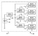
- an intrinsically safe battery powered electrical device 100includes a housing 102 which carries a battery receiving region 104 for receiving one or more batteries 106 , an energy limiter 108 , an energy converter 110 , and device electrical circuitry 112 which performs a function of the device.
- the configuration of the housing 102 and characteristics of the electrical circuitry 112are a function of the nature and function of the device 100 .
- the number and type of batteries 106 required to power the device 100 and hence the configuration of the battery receiving region 104are likewise a function of the electrical characteristics of the device electrical circuitry 112 , the desired operating time and size of the device 100 , and similar factors. In one implementation, however, the battery receiving region 104 is configured to accept one (1) or more standard AAA, AA, C, or D-size batteries.
- the batteries 106 , energy limiter 108 , energy converter 110 , and device electrical circuitry 112are configured as an intrinsically safe circuit which is suitable for use in hazardous locations.
- the energy limiter 108limits the available energy so that any spark or thermal effect produced during normal operation of the device 100 or under fault conditions is incapable of causing ignition of a mixture of a flammable or combustible material in air in the mixture's most easily ignitable concentration.
- the energy limiter 108should be located as near as practicable to the battery receiving region 104 , and the requisite electrical connections should be suitably spaced and insulated so as to prevent or otherwise reduce the likelihood of shorts, opens, or other faults.
- the energy limiter 108includes a series connected resistor 202 and fuse 204 .
- the resistor 202is selected to limit the instantaneous current available to the energy converter 110 and device electrical circuitry 112 to a level which satisfies the requirements of intrinsic safety.
- the fuse 204which is ordinarily implemented as a fast acting, encapsulated fuse, is selected primarily to limit thermal effects in the event of a fault condition.
- the energy limiter 108may also be implemented as a fuse protected or resistor protected shunt diode barrier. The latter implementations are particularly attractive where the physical configuration of the battery receiving region 104 or the associated battery contacts is such that relatively higher voltages may be encountered.
- the energy converter 110includes active electrical circuitry such as a direct current to direct current (DC to DC) converter which converts energy from the batteries 106 to a form suitable for powering the device electrical circuitry 112 .
- active electrical circuitrysuch as a direct current to direct current (DC to DC) converter which converts energy from the batteries 106 to a form suitable for powering the device electrical circuitry 112 .
- DC to DCdirect current to direct current
- the converter 110advantageously has an input dynamic range which accommodates the voltages produced by the relevant battery types.
- An alkaline batteryfor example has a nominal open circuit voltage of about 1.5 volts direct current (VDC), whereas a nickel metal hydride (NiMH) battery has a nominal open circuit voltage of about 1.2 VDC.
- the nominal open circuit input voltagewould thus range between about 2.4 for a device containing two NiMH batteries and 3.0 VDC for a device containing two alkaline batteries.
- the input dynamic rangeaccommodate decreases in input voltage which occur as the battery(ies) 106 are loaded and/or become discharged.
- the energy converter 110may be configured as a voltage source, a current source, or as having other output characteristics which are suitable for powering the device electrical circuitry 112 .
- the converter 110need not function as an ideal voltage or current source.
- converter 110is ordinarily designed to have an equivalent series or parallel resistance (as the case may be) which is compatible with the requirements of the device electrical circuitry 112 .
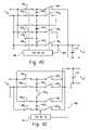
- the energy converter 110includes a charge pump which includes one more charge pump capacitors 302 , one or more semiconductor or other switches 304 , and a controller 308 . Where closed loop control of the energy converter 110 output is provided, a feedback signal 308 is provided to the controller 306 .
- FIG. 4Adepicts a charge pump which is particularly well to situations requiring step down voltage conversion.
- the charge pumpincludes a charge pump capacitor 402 , an output energy storage device such as a capacitor 404 , a controller 406 , and a semiconductor switch 408 .
- the controller 406varies the switch 406 between a first state (shown in FIG. 4A ) in which the charge pump capacitor 402 receives energy from the batteries 106 and a second state in which energy from the charge pump capacitor 402 is transferred to the output capacitor 404 .
- the controller 406may also include a control circuit which adjusts the operation of the switch 408 based on a measured value of the output voltage or current. Though illustrated as a single pole double throw (SPDT) switch, the switch 408 may also be implemented using semiconductor or other devices which function as single pole single throw (SPST) switches.
- SPDTsingle pole double throw
- SPSTsingle pole single throw
- FIG. 4BA charge pump which operates as a current source is shown in FIG. 4B .
- the circuitincludes a flying charge pump capacitor 402 , an output capacitor 404 , and a plurality of switches 408 1 , 408 2 , 408 3 , 408 4 .
- Energy from the charge pump capacitor 402is transferred to the device electrical circuitry side when the switches 408 3 , 408 4 are closed and switches 408 1 , 408 2 , are open (shown in FIG. 4B ); the flying capacitor 402 is charged when the switches 408 1 , 408 2 are closed and the switches 408 3 , 408 4 are open.
- a measurement apparatussuch as a current sense resistor 410 connected electrically in series with the device electrical circuitry 112 provides a feedback signal indicative of the device electrical circuitry current.
- the controller 406includes a control circuit 412 and an oscillator 414 which cooperate to control the operation of the switches 408 to provide the desired current output.
- FIG. 4CA charge pump which operates as a regulated voltage boost converter is shown in FIG. 4C .
- the circuitincludes first 402 1 and 402 2 second flying charge pump capacitors, an output capacitor 404 , and a plurality of switches 408 1 , 408 2 , 408 3 , 408 4 , 408 5 , 408 6 , 408 7 which are configured as a voltage doubler.
- the capacitors 402When connected to the output side (as shown in FIG. 4C ), the capacitors 402 are connected electrically in series; when connected to the input side, the capacitors 402 are connected electrically in parallel.
- the controller 406includes a control circuit 412 and an oscillator 414 .
- the controller 412receives a feedback signal 308 indicative of the converter 110 output voltage.
- the control circuit 412 and oscillator 414cooperate to control the operation of the switches 408 to provide the desired output voltage.
- a voltage dividermay also be implemented by connecting the capacitors in series when connected to the input and in parallel when connected to the output.
- FIG. 4DA charge pump which operates as an inverting boost converter is shown in FIG. 4D .
- the circuitincludes a plurality of flying charge pump capacitors 402 n , an output capacitor 404 , a plurality of switches 408 1-m , and a controller 406 .
- the circuitprovides up to approximately a negative n-times voltage boost.
- the controller 406provides the desired output regulation, if any.
- FIG. 4EA charge pump which provides multiple operating modes is shown in FIG. 4E .
- the circuitincludes first 402 1 and second 402 2 flying capacitors, an output capacitor 404 , a plurality of switches 408 1-9 , and a controller 406 .
- the inputis connected directly to the output by closing switches 408 1 and 408 5 .
- the circuitoperates as a step down converter. More particularly, the switches 408 1 and 408 5 are operated in a manner similar to that described above in connection with FIG. 4A so as to provide the desired output.
- the capacitors 402are charged in alternating clock phases so that the converter functions as a voltage doubler.
- the first capacitor 402 1is connected to the input through switches 408 3 and 408 4 , while the second capacitor 402 2 is stacked on top of the input and connected to the output through switches 408 5 and 408 6 .
- the second capacitor 402 2is connected to the input through switches 408 1 and 408 2 , while the first capacitor 402 1 is stacked on top of the input and connected to the output through switches 408 7 and 408 8 .
- the circuitfunctions as up to a one and one half times (1.5 ⁇ ) voltage converter.
- the capacitors 402are connected in series for charging and in parallel for transferring energy to the output.
- the capacitors 402are connected in parallel for charging and in series for transferring energy to the output so that the circuit functions as a voltage tripler.
- the desired operating modemay be dynamically selected by the controller 406 based on the feedback signal 308 .
- Such an implementationis particularly attractive in situations where the operating characteristics of the device electrical circuitry 112 may change based on ambient conditions or otherwise as a function of time, or where it is desirable to account for changes in the input voltage, for example as the batteries 106 discharge. While described as a circuit having multiple dynamically selectable operating modes, those of ordinary skill in the art will recognize that the circuit may be configured to provide only one or a subset of the described modes.
- the characteristics of the load presented by the device circuitry 112depend on the nature and function of the device 100 .
- the thermal characteristics of the various device 100 electrical componentsshould be selected so that the temperature rise under both operating and fault conditions is insufficient to cause ignition of flammable or combustible materials in the applicable hazardous location.
- the values of reactive and other energy storage componentsshould also be selected so that, in the event of a fault condition, the released energy is insufficient to cause ignition of flammable or combustible materials in the applicable hazardous location.
- Internal wiring and other connectionsshould be insulated and spaced appropriately.
- One source of guidance with respect to acceptable temperatures, component values, spacing, and the likeis the known UL 913 standard.
- a particular device 100may include a plurality of electrical circuits 112 0 , 112 1 , 112 2 . . . 112 p , each requiring a different supply voltage and/or current.
- a given device 100may include an input sensor or transducer circuit which operates at a first relatively high voltage, signal conditioning circuitry connected to the transducer and which also requires a negative supply voltage, logic circuitry for determining if the measured value reaches an alarm condition and which can operate directly from the voltage provided by the batteries 106 , and an alarm output or indicator circuitry such as one or more light emitting diodes (LEDs) which are advantageously powered by a current source.
- LEDslight emitting diodes
- the devicemay be provided with a plurality of energy converters 110 1 , 110 2 . . . 110 p , the number and function of which are determined based on the requirements of the various device electrical circuits 112 .
- More than one energy limiter 108may be provided.
- the device 100is advantageously constructed so that each energy limited circuit can be evaluated separately for the purpose of evaluating intrinsic safety. More specifically, the separation and/or spacing of the various energy limited circuits is advantageously established so that the various circuits cannot reasonably be expected to become short circuited or otherwise so that a fault in one of the circuits cannot reasonably be considered to affect the intrinsic safety of another.
- the battery receiving regionmay be configured to receive other generally cylindrical batteries, prismatic batteries, or coin cells.
- Other chemistriesare also contemplated, including but not limited to carbon zinc, lithium ion (LiIon), lithium iron disulfide (Li/FeS 2 ), and nickel cadmium (NiCd), provided that the batteries are otherwise suitable for use in the desired hazardous location.
- the battery receiving region 104may also be configured to accept only a single battery or three (3) or more batteries.
- the device 100may be of a size and weight which are suitable for a hand-held or otherwise readily human portable device.
- the device 100may also be configured for fixed or semi-fixed operation. In such a situation, the device 100 may be provided with electrical connections which allow the device to be connected to fixed, external wiring.
- the device 100may also be configured for operation with a transducer which is designed to be mounted at a fixed location.
- the batteries 106may be used to power the device 100 when the device is disconnected from the external source, in the event of a power failure, or otherwise in the absence of external power.
- the device 100is provided with an energy converter 110 configured to function as a battery charger. When external power is available, the converter 110 charges secondary battery(ies) 106 received in the battery receiving region 104 .
- the device 100may be provided with external contacts which allow battery(ies) 106 received in the receiving region 104 to be connected to an external battery charger.
- the energy converters 110may include a constant or a variable frequency oscillator. Regulation of the output voltage and/or current may also be provided by varying a duty cycle of the energy transfer or otherwise without an oscillator.
- the energy converters 110may be implemented using integrated circuits (ICs), discrete components, or combinations thereof. Those of ordinary skill in the art will also recognize that charge pump converter ICs are commercially available from a number of sources. Note also that the output capacitor 404 may be omitted, particularly where the device electrical circuitry 112 is tolerant of the resultant output swings.
- the device 100may be designed for use in other classes, divisions or groups (e.g., classes II or III, Division 2, Groups B-G, or the like).
- the device 100may also be designed to conform to IEC, ATEX/CENELEC, or other classification standards, for example in Zones 0, 1, or 2.
- Non-limiting examplesinclude communication devices, user operable signaling devices, measurement devices, automatic alarm or warning devices, flashlights and other light sources, actuators, and other operating devices.
- Examples of communication devicesinclude radio frequency or infrared receivers, transmitters, transceivers, pagers, wired or wireless intercoms, or other one or two-way communication devices.
- Signaling devicesinclude visual, audible, radio frequency or other signaling equipment, for example for signaling a distress or other condition.
- Examples of measurement devicesinclude devices for measuring ambient or operating conditions such as temperature, gas or other material concentrations, time, or the like.
- Exemplary actuatorsinclude pumps, fans, motors, actuators, and microelectromechanical systems (MEMS).
- measurement devicesinclude digital voltmeters, ammeters, ohmmeters, scales, and the like. Note also that, depending on the nature of the device 100 , the device may perform a function which is specific to a petrochemical, agricultural, mining, industrial, or other facility.
- the device 100Operation of the device 100 will now be described in relation to FIG. 6 .
- electrical energyis received from a battery or batteries disposed in the battery receiving region 104 of the device 100 .
- the energy converter(s) 110supplies energy from the battery(ies) 106 to the device electrical circuitry 112 .
- the device 100is operated in a hazardous location. In the event of a fault condition such as a component failure or a short circuit, the energy limiter(s) 108 limit the available energy at step 608 .
Landscapes
- Engineering & Computer Science (AREA)
- Power Engineering (AREA)
- Charge And Discharge Circuits For Batteries Or The Like (AREA)
- Secondary Cells (AREA)
- Emergency Protection Circuit Devices (AREA)
Abstract
Description
Claims (20)
Priority Applications (2)
| Application Number | Priority Date | Filing Date | Title |
|---|---|---|---|
| US12/429,435US7723950B2 (en) | 2006-09-19 | 2009-04-24 | Electrical device having a boost converter and an energy limiter |
| US12/769,322US7952321B2 (en) | 2006-09-19 | 2010-04-28 | Device having an energy converter and an energy limiter to limit supplied electrical energy |
Applications Claiming Priority (2)
| Application Number | Priority Date | Filing Date | Title |
|---|---|---|---|
| US11/523,157US7550943B2 (en) | 2006-09-19 | 2006-09-19 | Intrinsically safe battery-powered device |
| US12/429,435US7723950B2 (en) | 2006-09-19 | 2009-04-24 | Electrical device having a boost converter and an energy limiter |
Related Parent Applications (1)
| Application Number | Title | Priority Date | Filing Date |
|---|---|---|---|
| US11/523,157ContinuationUS7550943B2 (en) | 2006-09-19 | 2006-09-19 | Intrinsically safe battery-powered device |
Related Child Applications (1)
| Application Number | Title | Priority Date | Filing Date |
|---|---|---|---|
| US12/769,322ContinuationUS7952321B2 (en) | 2006-09-19 | 2010-04-28 | Device having an energy converter and an energy limiter to limit supplied electrical energy |
Publications (2)
| Publication Number | Publication Date |
|---|---|
| US20090206790A1 US20090206790A1 (en) | 2009-08-20 |
| US7723950B2true US7723950B2 (en) | 2010-05-25 |
Family
ID=39201054
Family Applications (3)
| Application Number | Title | Priority Date | Filing Date |
|---|---|---|---|
| US11/523,157ActiveUS7550943B2 (en) | 2006-09-19 | 2006-09-19 | Intrinsically safe battery-powered device |
| US12/429,435ActiveUS7723950B2 (en) | 2006-09-19 | 2009-04-24 | Electrical device having a boost converter and an energy limiter |
| US12/769,322Expired - Fee RelatedUS7952321B2 (en) | 2006-09-19 | 2010-04-28 | Device having an energy converter and an energy limiter to limit supplied electrical energy |
Family Applications Before (1)
| Application Number | Title | Priority Date | Filing Date |
|---|---|---|---|
| US11/523,157ActiveUS7550943B2 (en) | 2006-09-19 | 2006-09-19 | Intrinsically safe battery-powered device |
Family Applications After (1)
| Application Number | Title | Priority Date | Filing Date |
|---|---|---|---|
| US12/769,322Expired - Fee RelatedUS7952321B2 (en) | 2006-09-19 | 2010-04-28 | Device having an energy converter and an energy limiter to limit supplied electrical energy |
Country Status (5)
| Country | Link |
|---|---|
| US (3) | US7550943B2 (en) |
| EP (1) | EP2069686A2 (en) |
| CN (1) | CN101517315A (en) |
| AU (1) | AU2007297734A1 (en) |
| WO (1) | WO2008036252A2 (en) |
Cited By (3)
| Publication number | Priority date | Publication date | Assignee | Title |
|---|---|---|---|---|
| US20100207584A1 (en)* | 2006-09-19 | 2010-08-19 | Eveready Battery Company, Inc. | Electrical Device Having an Energy Converter and an Energy Limiter |
| US9778149B2 (en) | 2014-05-02 | 2017-10-03 | Swagelok Company | Fluid sample system and method |
| US10289182B2 (en) | 2016-04-01 | 2019-05-14 | Honeywell International Inc. | Intrinsically safe power conditioning circuit |
Families Citing this family (41)
| Publication number | Priority date | Publication date | Assignee | Title |
|---|---|---|---|---|
| US7651239B2 (en)* | 2006-09-19 | 2010-01-26 | Eveready Battery Co., Inc. | Intrinsically safe flashlight |
| GB2444984B (en)* | 2006-12-22 | 2011-07-13 | Wolfson Microelectronics Plc | Charge pump circuit and methods of operation thereof |
| GB2447426B (en)* | 2006-12-22 | 2011-07-13 | Wolfson Microelectronics Plc | Charge pump circuit and methods of operation thereof |
| TW200828751A (en)* | 2006-12-27 | 2008-07-01 | Fitipower Integrated Tech Inc | Charge pump |
| US20100073079A1 (en)* | 2008-09-24 | 2010-03-25 | Sony Ericsson Mobile Communications Ab | Bias arrangement and apparatus |
| US8754610B2 (en)* | 2009-05-22 | 2014-06-17 | Qualcomm Incorporated | System and method for supplying power to a load |
| CN101820181A (en)* | 2010-03-03 | 2010-09-01 | 海洋王照明科技股份有限公司 | Battery device |
| WO2011127376A2 (en)* | 2010-04-08 | 2011-10-13 | Bae Systems Information And Electronic Systems Integration Inc. | Method of extending the shelf-life of a coin cell in an application requiring high pulse current |
| US8841881B2 (en) | 2010-06-02 | 2014-09-23 | Bryan Marc Failing | Energy transfer with vehicles |
| DE102010032831B4 (en)* | 2010-07-30 | 2015-08-20 | Abb Technology Ag | Field device of a process automation system with an intrinsically safe power supply device |
| DE102010033954A1 (en)* | 2010-08-10 | 2012-02-16 | Krohne Messtechnik Gmbh | Power supply device |
| US8737947B2 (en)* | 2010-08-26 | 2014-05-27 | Infineon Technologies Ag | Transponder power supply, a transponder and a method for providing a transponder power supply current |
| US9705450B2 (en)* | 2011-06-24 | 2017-07-11 | The United States Of America As Represented By The Secretary Of The Navy | Apparatus and methods for time domain measurement of oscillation perturbations |
| JP5691950B2 (en)* | 2011-09-05 | 2015-04-01 | 株式会社デンソー | Voltage monitoring device |
| US9377340B2 (en)* | 2011-11-11 | 2016-06-28 | Rosemount Tank Radar Ab | Monitoring of floating roof tank |
| JP5849799B2 (en)* | 2012-03-19 | 2016-02-03 | 富士通株式会社 | Power circuit |
| WO2014075111A1 (en) | 2012-11-09 | 2014-05-15 | Ventulett Thomas P | System and method for i-safe mobile devices |
| WO2015032361A1 (en)* | 2013-09-09 | 2015-03-12 | 北京长吉加油设备有限公司 | Handheld fuel distributor control device with current-limiting battery pack |
| CN104843625A (en)* | 2014-02-19 | 2015-08-19 | 北京长吉加油设备有限公司 | Handheld fuel distributer control equipment having current limiting battery set |
| US10217472B2 (en) | 2013-12-28 | 2019-02-26 | Intel Corporation | System and method for data transmission over an audio jack |
| DE102016122002A1 (en)* | 2016-11-16 | 2018-05-17 | Dr. Ing. H.C. F. Porsche Aktiengesellschaft | Vehicle, in particular an electric vehicle or a hybrid vehicle and method for charging an energy storage cell of a vehicle |
| US11153819B2 (en)* | 2017-02-06 | 2021-10-19 | Itron Networked Solutions, Inc. | Battery control for safeguarding lower voltage integrated circuits |
| FR3068899B1 (en)* | 2017-07-13 | 2020-09-04 | Exel Ind | GENERATOR FOR USE IN AN EXPLOSIVE ATMOSPHERE ZONE AND SET INCLUDING AN ELECTROSTATIC SPRAYER AND SUCH A GENERATOR |
| DE102017010107A1 (en)* | 2017-10-26 | 2019-05-16 | Bartec Gmbh | Device for use in hazardous areas |
| US10879519B2 (en) | 2018-12-17 | 2020-12-29 | Bayco Products, Inc. | Spark protection apparatus for intrinsically safe, battery-operated devices |
| US10790742B1 (en) | 2019-04-17 | 2020-09-29 | Dialog Semiconductor (Uk) Limited | Multi-level power converter with improved transient load response |
| US10811974B1 (en) | 2019-04-17 | 2020-10-20 | Dialog Semiconductor (Uk) Limited | Power converter |
| US10756623B1 (en)* | 2019-04-17 | 2020-08-25 | Dialog Semiconductor (Uk) Limited | Low loss power converter |
| WO2020262545A1 (en)* | 2019-06-27 | 2020-12-30 | 日本精機株式会社 | Sensing device |
| US11211785B2 (en) | 2019-10-02 | 2021-12-28 | Motorola Solutions, Inc. | Dynamic battery voltage restriction for hazardous environments |
| CN111120002A (en)* | 2019-12-20 | 2020-05-08 | 航天重型工程装备有限公司 | Safe type driving data recorder of essence |
| US11387645B2 (en) | 2020-05-08 | 2022-07-12 | Motorola Solutions, Inc. | Apparatus and method for adaptive active current limit protection |
| US11264814B2 (en) | 2020-05-08 | 2022-03-01 | Motorola Solutions, Inc. | Method and apparatus for connecting a battery power source to a portable electronic device |
| US11228243B2 (en) | 2020-06-12 | 2022-01-18 | Dialog Semiconductor (Uk) Limited | Power converter with reduced RMS input current |
| US11456663B2 (en) | 2020-06-12 | 2022-09-27 | Dialog Semiconductor (Uk) Limited | Power converter with reduced root mean square input current |
| US11637491B2 (en) | 2020-12-03 | 2023-04-25 | Dialog Semiconductor (Uk) Limited | Multi-stage power converter |
| US11496051B2 (en) | 2020-12-16 | 2022-11-08 | Dialog Semiconductor (Uk) Limited | Power converter |
| US11929672B2 (en) | 2021-08-06 | 2024-03-12 | Renesas Design (UK) Limited | Inverting buck-boost converter |
| US11990831B2 (en) | 2021-08-06 | 2024-05-21 | Renesas Design (UK) Limited | Hybrid buck boost converter with reduced inductor current |
| CN113556853A (en)* | 2021-08-18 | 2021-10-26 | 东莞泛美光电有限公司 | Composite intrinsic safety circuit |
| US11967901B2 (en) | 2021-12-09 | 2024-04-23 | Renesas Design (UK) Limited | Hybrid multi-phase power converter with phase shedding |
Citations (21)
| Publication number | Priority date | Publication date | Assignee | Title |
|---|---|---|---|---|
| US4164145A (en) | 1978-03-20 | 1979-08-14 | De Laval Turbine Inc. | Self-powered electrical meter for display of a liquid-level or the like measurement |
| US4346329A (en) | 1979-08-27 | 1982-08-24 | Schmidt Robert C H | Aiming post light |
| SU1154461A1 (en) | 1983-12-08 | 1985-05-07 | Ордена Октябрьской Революции И Ордена Трудового Красного Знамени Институт Горного Дела Им.А.А.Скочинского | Visual monitoring device for mines |
| EP0385417A2 (en) | 1989-02-28 | 1990-09-05 | Canon Kabushiki Kaisha | An ink jet recording apparatus |
| US5149190A (en) | 1989-05-24 | 1992-09-22 | Bay Industrial And Mine Tech Inc. | Portable safety device |
| WO1993024789A1 (en) | 1992-05-30 | 1993-12-09 | The Wolf Safety Lamp Company Limited | Improvements in or relating to search lamps and torches |
| US5386592A (en) | 1993-09-07 | 1995-02-07 | Checkeroski; Mark | Headband and flashlight holding construction |
| US5685632A (en) | 1995-05-31 | 1997-11-11 | Rayovac Corporation | Electrically conductive plastic light source |
| US6556067B2 (en) | 2000-06-13 | 2003-04-29 | Linfinity Microelectronics | Charge pump regulator with load current control |
| WO2004025168A1 (en) | 2002-09-16 | 2004-03-25 | Peter Moser | Pocket light comprising at least one led as an illuminant |
| US6727805B2 (en) | 2002-05-14 | 2004-04-27 | Fire Factory, Llc | Signaling retention device |
| US20040124782A1 (en) | 2002-12-31 | 2004-07-01 | Sun Yu | Step down circuit for an LED flashlight |
| US6798348B1 (en) | 2003-04-03 | 2004-09-28 | Scott Wilker | Ergonomically designed tool handle |
| US6857756B2 (en) | 2001-04-11 | 2005-02-22 | General Manufacturing, Inc. | LED work light |
| US6857758B1 (en) | 2000-02-25 | 2005-02-22 | Streamilght, Incorporated | Solid state light source, as for a flashlight |
| US6859145B2 (en) | 2003-04-03 | 2005-02-22 | Scott Wilker | Safety system |
| US20050040773A1 (en) | 1998-03-19 | 2005-02-24 | Ppt Vision, Inc. | Method and apparatus for a variable intensity pulsed L.E.D. light |
| US20060109662A1 (en) | 2001-04-11 | 2006-05-25 | Reiff Paul J | Intrinsically safe light |
| US20070159816A1 (en) | 2006-01-10 | 2007-07-12 | Bijan Bayat | Combination task lamp and flash light |
| US20080068832A1 (en) | 2006-09-19 | 2008-03-20 | David Spartano | Intrinsically safe flashlight |
| US7550943B2 (en)* | 2006-09-19 | 2009-06-23 | Eveready Battery Company, Inc. | Intrinsically safe battery-powered device |
Family Cites Families (11)
| Publication number | Priority date | Publication date | Assignee | Title |
|---|---|---|---|---|
| US3711768A (en)* | 1971-04-05 | 1973-01-16 | B Frazin | Combined electric continuity checker and flashlight |
| US3973139A (en)* | 1973-05-23 | 1976-08-03 | Rca Corporation | Low power counting circuits |
| GB2222449B (en) | 1988-09-06 | 1992-01-02 | Top Line Leisure Ltd | Improvements in or relating to search lamps and torches |
| US5563456A (en)* | 1992-02-06 | 1996-10-08 | Murphy Management Inc. | Solar powered annunciator |
| US5438225A (en)* | 1992-02-06 | 1995-08-01 | Murphy Management Inc. | Solar powered annuciator |
| US5262728A (en)* | 1992-08-25 | 1993-11-16 | Shershen Eugene D | Combination flashlight/lantern electric continuity tester |
| CN2515509Y (en) | 2002-01-15 | 2002-10-09 | 杨炳和 | Explosion-proof safety miner's lamp |
| JP3759134B2 (en)* | 2003-08-29 | 2006-03-22 | ローム株式会社 | Power supply |
| CN2723811Y (en) | 2004-07-19 | 2005-09-07 | 胡宪亮 | Wood safety portable lamp |
| US7241025B2 (en)* | 2005-01-24 | 2007-07-10 | Surefire, Llc | Switch actuated flashlight with current limiter |
| EP1772664B1 (en)* | 2005-10-07 | 2009-12-09 | Black & Decker, Inc. | Flashlight |
- 2006
- 2006-09-19USUS11/523,157patent/US7550943B2/enactiveActive
- 2007
- 2007-09-18AUAU2007297734Apatent/AU2007297734A1/ennot_activeAbandoned
- 2007-09-18WOPCT/US2007/020171patent/WO2008036252A2/enactiveApplication Filing
- 2007-09-18EPEP07838388Apatent/EP2069686A2/ennot_activeWithdrawn
- 2007-09-18CNCNA2007800347871Apatent/CN101517315A/enactivePending
- 2009
- 2009-04-24USUS12/429,435patent/US7723950B2/enactiveActive
- 2010
- 2010-04-28USUS12/769,322patent/US7952321B2/ennot_activeExpired - Fee Related
Patent Citations (24)
| Publication number | Priority date | Publication date | Assignee | Title |
|---|---|---|---|---|
| US4164145A (en) | 1978-03-20 | 1979-08-14 | De Laval Turbine Inc. | Self-powered electrical meter for display of a liquid-level or the like measurement |
| US4346329A (en) | 1979-08-27 | 1982-08-24 | Schmidt Robert C H | Aiming post light |
| SU1154461A1 (en) | 1983-12-08 | 1985-05-07 | Ордена Октябрьской Революции И Ордена Трудового Красного Знамени Институт Горного Дела Им.А.А.Скочинского | Visual monitoring device for mines |
| EP0385417A2 (en) | 1989-02-28 | 1990-09-05 | Canon Kabushiki Kaisha | An ink jet recording apparatus |
| US5149190A (en) | 1989-05-24 | 1992-09-22 | Bay Industrial And Mine Tech Inc. | Portable safety device |
| WO1993024789A1 (en) | 1992-05-30 | 1993-12-09 | The Wolf Safety Lamp Company Limited | Improvements in or relating to search lamps and torches |
| US5386592A (en) | 1993-09-07 | 1995-02-07 | Checkeroski; Mark | Headband and flashlight holding construction |
| US5685632A (en) | 1995-05-31 | 1997-11-11 | Rayovac Corporation | Electrically conductive plastic light source |
| US7186000B2 (en) | 1998-03-19 | 2007-03-06 | Lebens Gary A | Method and apparatus for a variable intensity pulsed L.E.D. light |
| US20050040773A1 (en) | 1998-03-19 | 2005-02-24 | Ppt Vision, Inc. | Method and apparatus for a variable intensity pulsed L.E.D. light |
| US6857758B1 (en) | 2000-02-25 | 2005-02-22 | Streamilght, Incorporated | Solid state light source, as for a flashlight |
| US6556067B2 (en) | 2000-06-13 | 2003-04-29 | Linfinity Microelectronics | Charge pump regulator with load current control |
| US20060109662A1 (en) | 2001-04-11 | 2006-05-25 | Reiff Paul J | Intrinsically safe light |
| US6857756B2 (en) | 2001-04-11 | 2005-02-22 | General Manufacturing, Inc. | LED work light |
| US6979100B2 (en) | 2001-04-11 | 2005-12-27 | General Manufacturing, Inc. | LED work light |
| US6727805B2 (en) | 2002-05-14 | 2004-04-27 | Fire Factory, Llc | Signaling retention device |
| WO2004025168A1 (en) | 2002-09-16 | 2004-03-25 | Peter Moser | Pocket light comprising at least one led as an illuminant |
| US6987366B2 (en) | 2002-12-31 | 2006-01-17 | Sun Yu | Step down circuit for an LED flashlight |
| US20040124782A1 (en) | 2002-12-31 | 2004-07-01 | Sun Yu | Step down circuit for an LED flashlight |
| US6859145B2 (en) | 2003-04-03 | 2005-02-22 | Scott Wilker | Safety system |
| US6798348B1 (en) | 2003-04-03 | 2004-09-28 | Scott Wilker | Ergonomically designed tool handle |
| US20070159816A1 (en) | 2006-01-10 | 2007-07-12 | Bijan Bayat | Combination task lamp and flash light |
| US20080068832A1 (en) | 2006-09-19 | 2008-03-20 | David Spartano | Intrinsically safe flashlight |
| US7550943B2 (en)* | 2006-09-19 | 2009-06-23 | Eveready Battery Company, Inc. | Intrinsically safe battery-powered device |
Non-Patent Citations (46)
| Title |
|---|
| 3D Instruments, LLC, DPG-6600 Battery-Powered Digital Gauge data sheet, 2004, 4 pages, Anaheim CA. |
| AEMC Instruments, Digital Ground Resistance Tester Models 4620 & 4630 data sheet, Aug. 2002, pages 1-6, www.aemc.com. |
| Analog Devices, Leading Semiconductors for Wireless Handsets, data sheet, 1995-2006, 12 pages. |
| Author Unknown, Hazardous (Classified) Locations, downloaded Aug. 15, 2006, pages 10,13,15-16,18,25, http://www.labtrain.noaa.gov/osha600/mod07/0713--.htm. |
| Author Unknown, Intrinsic Safety Basic Principles, Technology For Safety, downloaded Aug. 17, 2006, pages 159-172. |
| Batteries in a Portable World, Protection Circuits, 2001, 4 pages. |
| Beka Associates, Ltd, Instruction sheet for BA369 Intrinsically safe battery powered clock, Dec. 2004, pp. 1-4, www.beka.co.uk. |
| Bluechips Technology, BCT3511S DC/DC Converter for 1 Watt White LED data sheet, 2005, pp. 1-9, www. bluechipstech.com. |
| Communication pursuant to Article 94(3) EPC, European Patent Office, 80298 Munich, Germany, Application No. 07 838 385.8-2423,Mailed Oct. 8, 2009. |
| Communications-Applied Technology Products from Communication-Applied Technology Product Links and Presentations sheet, 2001-2003, 2 pages, Reston, Virginia. |
| Communications-Applied Technology, AMCVIS-Advanced Multi-Channel Vehicle Inercom System Field Commentary, 2001-2003, 1 page. |
| Communications-Applied Technology, AMCVIS-Advanced Multi-Channel Vehicle Intercom System Documentation, 2001-2003, 1 page, Reston, Virginia. |
| Communications-Applied Technology, AMCVIS-Advanced Multi-Channel Vehicle Intercom System Frequently Asked Questions, 2001-2003, 1 page. Reston, Virginia. |
| Communications-Applied Technology, AMCVIS-Advanced Multi-Channel Vehicle Intercom System Price List, 2001-2003, 5 pages, Reston, Virginia. |
| Communications-Applied Technology, Headsets for Intrinsically Safe Wireless Intercom System Description and Features, 2001-2003, 4 pages, Reston, Virginia. |
| Communications-Applied Technology, Headsets for Intrinsically Safe Wireless Intercom System product sheet, 2001-2003, 2 pages, Reston, Virginia. |
| Cree Lighting, Cree XLamp 7090 Packaged LEDs data sheet, 2004, pp. 1-19, www.cree.com/xlamp. |
| Dallas Semiconductor, Maxim Application Note 1021 Buck/Boost Charge-Pump Regulator Powers White LEDs from a Wide 1.6V to 5.5V Input, Mar. 27, 2003, 2 pages, http://www.maxim-ic.com/an1021. |
| Dallas Semiconductors, Maxim Application Note 1037 Charge-Pump Step-Up DC-DC Converter Solutions for Powering White LEDs in Series or Parallel Connections, Apr. 23, 2002, pages 1-12. |
| Dallas Semiconductors, Maxim Application note 725 DC/DC Conversion without Inductors, Dec. 29, 2000, 8 pages, http://www.maxim-ic.com/legal. |
| ECOM Instruments, EX-Penlight data sheet and operating instructions, downloaded Sep. 12, 2006, 9 pages www.ecom-ex.com. |
| ECOM Instruments, Intrinisically-Safe Laserpointer Ex Point 01 data sheet, 2001-2004, 1 page, http://www.ecomus-ex.com/us/products/flashlights/laserpointer01/detai . . . . |
| ECOM Instruments, Intrinsically Safe LED pocket Flashlight Lite-Ex LED 30 data sheet, downloaded Feb. 2002, 1 page. |
| ECOM Instruments, Intrinsically-Safe Handlamp H-4 DC A, data sheet and instruction manual, Nov. 2001, 12 pages, www.ecom-ex.com. |
| ECOM Instruments, Intrinsically-Safe Ultrasonic Wall Thickness Gauge 1071-Ex data sheet, downloaded Sep. 11, 2006, 1 page, www.ecom-ex.com. |
| ECOM Instruments, Lite-Ex HD 10, Instruction Manual, Feb. 2001, 7 pages, www.ecom-ex.com. |
| ECOM Instruments, Lite-Ex LED 30 operating instructions, downloaded Sep. 12, 2006, 9 pages, www.ecom-ex.com. |
| Energizer, 1259 Industrial Safety Flashlight Engineering Datasheet, May 2005, 1 page, www.energizer.com. |
| Energizer, 1359 Industrial Flashlight Engineering Datasheet, May 2005, 1 page, www.energizer.com. |
| Energizer, 459 Industrial Flashlight Engineering Datasheet, May 2005, 1 page, www.energizer.com. |
| GM International Technology for Safety, Understanding Hazardous Location data sheet, downloaded Aug. 17, 2006, 1 page, www.gmisafety.com. |
| Hazardous Area Direct, Definitions of Classes and Zones, downloaded Jul. 26, 2006, 8 pages. http://www.hazardousareadirect.com/Classificationinfo/Definitions.htm. |
| Hazardous Area Direct, i.roc 627 FM Class 1 Div. 1/ATEX Zone 1 PDA + 1 GB data sheet, 2004, 6 pages. |
| Hazardous Area Direct, TMRT 1Ex Intrinsically Safe Laser Tachometer data sheet, 2004, 2 pages. |
| Ken Wasko, The Inside on Intrinsically Safe Radios, Private Wireless, Mar. 2003, pp. 14-16. |
| Linear Technology, LTC3204-3.3/LTC3204-5/LTC3204B-3.3/LTC3204B-5 Low Noise Redulated Charge Pump in 2x2 DFN data sheet, 2004, pp. 1-12, Milpitas, CA, www.linear.com. |
| Linear Technology, LTC3215 700mA Low Noise High Current LED Charge Pump data sheet, 2005, pp. 1-12, Milpitas, CA, www.linear.com. |
| Metrix, MX 57Ex 50,000-count TRMS Digital Multimeter data sheet, 2 pages, downloaded Sep. 12, 2006, www.chauvin-amoux.co.uk. |
| Omega, OM-CP-RHTEMP1000IS Intrinsically Safe Humidity and Temperature Datalogger data sheet, downloaded Aug. 17, 2006, 2 pages, omega.com. |
| Patent Cooperation Treaty (PCT) International Search Report and Written Opinion for Application No. PCT/US2007/020171, filed Sep. 18, 2007, mailed Apr. 22, 2008, European Patent Office, Netherlands. |
| Patent Cooperation Treaty (PCT), International Search Report and Written Opinion for Application PCT/US2007/020168, filed Sep. 18, 2007, mailed Jan. 23, 2008, European Patent Office , Netherlands. |
| SA EX Instruments, The L2000 Explosion Proof Rechargeable Flashlight product sheet, 2006, 2 pages. |
| SA EX Instruments, The Lite-EX 15, 20, 23, 25 series of Explosion Proof Flashlights product sheet, 2006, 2 pages. |
| Underwriters Laboratories, Inc., Definitions of Commonly used hazardous locations terminology, Hazardous Locations, 2005, 6 pages. |
| Underwriters Lagoratories, Inc. (UL), UL 913 Intrinsically Safe Apparatus and Associated Apparatus for Use in Class I, II, and III, Division 1, Hazardous (Classified) Location, Aug. 8, 2002, pages title page-B2, sixth edition. |
| US Patent and Trademark Office Office Communication for U.S. Appl. No. 11/523,149, filed Sep. 19, 2006, mailed Apr. 15, 2009, US Patent and Trademark Office, Alexandria, VA. |
Cited By (4)
| Publication number | Priority date | Publication date | Assignee | Title |
|---|---|---|---|---|
| US20100207584A1 (en)* | 2006-09-19 | 2010-08-19 | Eveready Battery Company, Inc. | Electrical Device Having an Energy Converter and an Energy Limiter |
| US7952321B2 (en)* | 2006-09-19 | 2011-05-31 | Eveready Battery Company, Inc. | Device having an energy converter and an energy limiter to limit supplied electrical energy |
| US9778149B2 (en) | 2014-05-02 | 2017-10-03 | Swagelok Company | Fluid sample system and method |
| US10289182B2 (en) | 2016-04-01 | 2019-05-14 | Honeywell International Inc. | Intrinsically safe power conditioning circuit |
Also Published As
| Publication number | Publication date |
|---|---|
| CN101517315A (en) | 2009-08-26 |
| US7550943B2 (en) | 2009-06-23 |
| US20080079393A1 (en) | 2008-04-03 |
| AU2007297734A1 (en) | 2008-03-27 |
| US20090206790A1 (en) | 2009-08-20 |
| US7952321B2 (en) | 2011-05-31 |
| WO2008036252A3 (en) | 2008-06-19 |
| US20100207584A1 (en) | 2010-08-19 |
| WO2008036252A2 (en) | 2008-03-27 |
| EP2069686A2 (en) | 2009-06-17 |
Similar Documents
| Publication | Publication Date | Title |
|---|---|---|
| US7723950B2 (en) | Electrical device having a boost converter and an energy limiter | |
| CN101517307B (en) | Intrinsically safe flashlight | |
| US8648567B2 (en) | Enhanced portable battery powered electrical appliance | |
| US20090051320A1 (en) | Rechargeable Battery and Method for its Operation | |
| US7557585B2 (en) | Abnormal voltage detection apparatus for detecting voltage abnormality in assembled battery | |
| AU2010362640B2 (en) | Intrinsically safe backup power supply for combustible environments | |
| RU2363076C2 (en) | Battery power supply system with internal protection used in underground mining | |
| US20070152637A1 (en) | Rechargeable lithium battery protection device | |
| KR200363322Y1 (en) | portable battery pack | |
| EP3087651B1 (en) | Power management system with selective source depletion | |
| HK1166120A (en) | Intrinsically safe flashlight | |
| Rajani et al. | Design and Performance of Solar-powered Telescopic Lamp | |
| AU2007323912A1 (en) | Voltage clamp to allow low-temperature recharging of nickel-cadmium batteries in emergency lighting fixtures and method of using | |
| GB2477797A (en) | Multiple Battery Charger | |
| UA9853U (en) | Lighting unit |
Legal Events
| Date | Code | Title | Description |
|---|---|---|---|
| STCF | Information on status: patent grant | Free format text:PATENTED CASE | |
| FPAY | Fee payment | Year of fee payment:4 | |
| AS | Assignment | Owner name:ENERGIZER BRANDS, LLC, MISSOURI Free format text:ASSIGNMENT OF ASSIGNORS INTEREST;ASSIGNOR:EVEREADY BATTERY COMPANY, INC.;REEL/FRAME:036019/0814 Effective date:20150601 | |
| AS | Assignment | Owner name:JPMORGAN CHASE BANK, N.A., AS AGENT, ILLINOIS Free format text:SECURITY AGREEMENT;ASSIGNOR:ENERGIZER BRANDS, LLC;REEL/FRAME:036106/0392 Effective date:20150630 | |
| AS | Assignment | Owner name:ENERGIZER BRANDS, LLC, MISSOURI Free format text:CORRECTIVE ASSIGNMENT TO CORRECT THE APPLICATION NUMBER 29/499,135 PREVIOUSLY RECORDED AT REEL: 036019 FRAME: 814. ASSIGNOR(S) HEREBY CONFIRMS THE ASSIGNMENT;ASSIGNOR:EVEREADY BATTERY COMPANY;REEL/FRAME:040054/0660 Effective date:20160601 | |
| MAFP | Maintenance fee payment | Free format text:PAYMENT OF MAINTENANCE FEE, 8TH YEAR, LARGE ENTITY (ORIGINAL EVENT CODE: M1552) Year of fee payment:8 | |
| AS | Assignment | Owner name:ENERGIZER BRANDS, LLC, MISSOURI Free format text:TERMINATION AND RELEASE OF SECURITY INTEREST IN PATENT RIGHTS;ASSIGNOR:JPMORGAN CHASE BANK, N.A., AS ADMINISTRATIVE AGENT;REEL/FRAME:048888/0300 Effective date:20190102 Owner name:JPMORGAN CHASE BANK, N.A., AS ADMINISTRATIVE AGENT, ILLINOIS Free format text:PATENT SECURITY AGREEMENT;ASSIGNORS:ENERGIZER HOLDINGS, INC.;AMERICAN COVERS, LLC;ASSOCIATED PRODUCTS, LLC;AND OTHERS;REEL/FRAME:048029/0246 Effective date:20190102 Owner name:JPMORGAN CHASE BANK, N.A., AS ADMINISTRATIVE AGENT Free format text:PATENT SECURITY AGREEMENT;ASSIGNORS:ENERGIZER HOLDINGS, INC.;AMERICAN COVERS, LLC;ASSOCIATED PRODUCTS, LLC;AND OTHERS;REEL/FRAME:048029/0246 Effective date:20190102 | |
| AS | Assignment | Owner name:JPMORGAN CHASE BANK, N.A., AS ADMINISTRATIVE AGENT, ILLINOIS Free format text:PATENT SECURITY AGREEMENT;ASSIGNORS:ENERGIZER BRANDS, LLC;ENERGIZER AUTO, INC.;REEL/FRAME:054875/0504 Effective date:20201222 Owner name:JPMORGAN CHASE BANK, N.A., AS ADMINISTRATIVE AGENT, ILLINOIS Free format text:PATENT SECURITY AGREEMENT;ASSIGNORS:ENERGIZER BRANDS, LLC;ENERGIZER AUTO, INC.;REEL/FRAME:054875/0651 Effective date:20201222 | |
| MAFP | Maintenance fee payment | Free format text:PAYMENT OF MAINTENANCE FEE, 12TH YEAR, LARGE ENTITY (ORIGINAL EVENT CODE: M1553); ENTITY STATUS OF PATENT OWNER: LARGE ENTITY Year of fee payment:12 | |
| AS | Assignment | Owner name:JPMORGAN CHASE BANK, N.A., AS COLLATERAL AGENT, ILLINOIS Free format text:AMENDED AND RESTATED INTELLECTUAL PROPERTY SECURITY AGREEMENT;ASSIGNORS:ENERGIZER BRANDS, LLC;ENERGIZER AUTO, INC.,;ENERGIZER AUTO SALES, INC.;REEL/FRAME:070565/0282 Effective date:20250319 |