US7723756B2 - Silicon pillars for vertical transistors - Google Patents
Silicon pillars for vertical transistorsDownload PDFInfo
- Publication number
- US7723756B2 US7723756B2US11/683,122US68312207AUS7723756B2US 7723756 B2US7723756 B2US 7723756B2US 68312207 AUS68312207 AUS 68312207AUS 7723756 B2US7723756 B2US 7723756B2
- Authority
- US
- United States
- Prior art keywords
- trenches
- substrate
- depth
- hard mask
- regions
- Prior art date
- Legal status (The legal status is an assumption and is not a legal conclusion. Google has not performed a legal analysis and makes no representation as to the accuracy of the status listed.)
- Expired - Lifetime, expires
Links
Images


Classifications
- H—ELECTRICITY
- H10—SEMICONDUCTOR DEVICES; ELECTRIC SOLID-STATE DEVICES NOT OTHERWISE PROVIDED FOR
- H10B—ELECTRONIC MEMORY DEVICES
- H10B12/00—Dynamic random access memory [DRAM] devices
- H10B12/30—DRAM devices comprising one-transistor - one-capacitor [1T-1C] memory cells
- H10B12/39—DRAM devices comprising one-transistor - one-capacitor [1T-1C] memory cells the capacitor and the transistor being in a same trench
- H10B12/395—DRAM devices comprising one-transistor - one-capacitor [1T-1C] memory cells the capacitor and the transistor being in a same trench the transistor being vertical
- H—ELECTRICITY
- H01—ELECTRIC ELEMENTS
- H01L—SEMICONDUCTOR DEVICES NOT COVERED BY CLASS H10
- H01L21/00—Processes or apparatus adapted for the manufacture or treatment of semiconductor or solid state devices or of parts thereof
- H01L21/02—Manufacture or treatment of semiconductor devices or of parts thereof
- H01L21/04—Manufacture or treatment of semiconductor devices or of parts thereof the devices having potential barriers, e.g. a PN junction, depletion layer or carrier concentration layer
- H01L21/18—Manufacture or treatment of semiconductor devices or of parts thereof the devices having potential barriers, e.g. a PN junction, depletion layer or carrier concentration layer the devices having semiconductor bodies comprising elements of Group IV of the Periodic Table or AIIIBV compounds with or without impurities, e.g. doping materials
- H01L21/30—Treatment of semiconductor bodies using processes or apparatus not provided for in groups H01L21/20 - H01L21/26
- H01L21/302—Treatment of semiconductor bodies using processes or apparatus not provided for in groups H01L21/20 - H01L21/26 to change their surface-physical characteristics or shape, e.g. etching, polishing, cutting
- H01L21/306—Chemical or electrical treatment, e.g. electrolytic etching
- H01L21/3065—Plasma etching; Reactive-ion etching
- H—ELECTRICITY
- H01—ELECTRIC ELEMENTS
- H01L—SEMICONDUCTOR DEVICES NOT COVERED BY CLASS H10
- H01L21/00—Processes or apparatus adapted for the manufacture or treatment of semiconductor or solid state devices or of parts thereof
- H01L21/02—Manufacture or treatment of semiconductor devices or of parts thereof
- H01L21/04—Manufacture or treatment of semiconductor devices or of parts thereof the devices having potential barriers, e.g. a PN junction, depletion layer or carrier concentration layer
- H01L21/18—Manufacture or treatment of semiconductor devices or of parts thereof the devices having potential barriers, e.g. a PN junction, depletion layer or carrier concentration layer the devices having semiconductor bodies comprising elements of Group IV of the Periodic Table or AIIIBV compounds with or without impurities, e.g. doping materials
- H01L21/30—Treatment of semiconductor bodies using processes or apparatus not provided for in groups H01L21/20 - H01L21/26
- H01L21/302—Treatment of semiconductor bodies using processes or apparatus not provided for in groups H01L21/20 - H01L21/26 to change their surface-physical characteristics or shape, e.g. etching, polishing, cutting
- H01L21/306—Chemical or electrical treatment, e.g. electrolytic etching
- H01L21/308—Chemical or electrical treatment, e.g. electrolytic etching using masks
- H01L21/3081—Chemical or electrical treatment, e.g. electrolytic etching using masks characterised by their composition, e.g. multilayer masks, materials
- H—ELECTRICITY
- H10—SEMICONDUCTOR DEVICES; ELECTRIC SOLID-STATE DEVICES NOT OTHERWISE PROVIDED FOR
- H10B—ELECTRONIC MEMORY DEVICES
- H10B12/00—Dynamic random access memory [DRAM] devices
- H10B12/01—Manufacture or treatment
- H10B12/02—Manufacture or treatment for one transistor one-capacitor [1T-1C] memory cells
- H10B12/05—Making the transistor
- H10B12/053—Making the transistor the transistor being at least partially in a trench in the substrate
- H—ELECTRICITY
- H10—SEMICONDUCTOR DEVICES; ELECTRIC SOLID-STATE DEVICES NOT OTHERWISE PROVIDED FOR
- H10D—INORGANIC ELECTRIC SEMICONDUCTOR DEVICES
- H10D30/00—Field-effect transistors [FET]
- H10D30/01—Manufacture or treatment
- H10D30/021—Manufacture or treatment of FETs having insulated gates [IGFET]
- H10D30/025—Manufacture or treatment of FETs having insulated gates [IGFET] of vertical IGFETs
- H—ELECTRICITY
- H10—SEMICONDUCTOR DEVICES; ELECTRIC SOLID-STATE DEVICES NOT OTHERWISE PROVIDED FOR
- H10D—INORGANIC ELECTRIC SEMICONDUCTOR DEVICES
- H10D89/00—Aspects of integrated devices not covered by groups H10D84/00 - H10D88/00
- H10D89/211—Design considerations for internal polarisation
Definitions
- the present inventionrelates generally to the field of semiconductor fabrication and more specifically to the field of fabricating silicon pillars.
- DRAMDynamic Random Access Memory
- RAMsemiconductor Random Access Memory
- DRAM circuit manufacturersincreasingly face, difficulties with scaling.
- One way of forming smaller transistorsis the formation of vertical transistors.
- Vertical transistorshave the advantage of taking up less substrate real estate.
- the vertical transistorcan reduce threshold voltage variations due to electrical and geometric sensitivities to an acceptable level because the channel of the transistor can remain sufficiently long despite occupying less real estate on the substrate.
- the long channel of vertical transistorsallows a thicker gate dielectric that can be properly scaled in proportion to the channel length. This can also provide reliability and protection against wearout.
- a method of forming pillars in a substrate for integrate circuitscomprises forming a lower hard mask on a substrate and depositing a upper hard mask over the lower hard mask.
- a first resist maskis formed over the upper hard mask to form first exposed portions of the upper hard mask and the lower hard mask.
- the first exposed portions of the upper hard mask and the lower hard maskare removed.
- a second resist maskis formed over the upper hard mask to form second exposed portions of the upper hard mask after removing the first resist mask.
- the second exposed portions of the upper hard maskare removed to form third exposed portions of the lower hard mask.
- the substrateis etched selectively against the upper hard mask and the lower hard mask after removing the second exposed portions of the upper hard mask.
- the third exposed portions of the lower hard maskare removed after etching the substrate.
- the substrateis etched using the upper hard mask to form a plurality of active areas and trenches after removing the third exposed portions of the lower hard mask.
- a method of forming silicon pillars for vertical transistors for integrated circuitscomprises forming a first mask layer over a silicon substrate and forming a second mask layer over the first mask layer.
- the first mask layeris patterned to expose a first portion of the silicon substrate.
- the second mask layeris patterned to form an unmasked portion of the first mask layer after patterning the first mask layer.
- the methodfurther comprises etching the first exposed portion of the silicon substrate to a first depth and removing the unmasked portion of the first mask layer to expose a second portion of the silicon substrate. Finally, the first exposed portion of the substrate is etched to a second depth and the second exposed portion is etched to a third depth.
- a masking structure for forming pillars in a substratecomprises a substrate and a first hard mask over the substrate.
- the first hard maskcomprises a plurality of parallel lines.
- the structurefurther comprises a second hard mask directly over the first hard mask, wherein the second hard mask is a plurality of islands on the lines of the first hard mask.
- a method of forming a silicon pillarcomprises forming an oxide layer over a silicon substrate and depositing a nitride layer over the oxide layer. A first portion of the nitride layer and the oxide layer are removed to expose a plurality of trench regions in the silicon substrate and to form an oxide hard mask. A second portion of the nitride layer is removed to form a nitride hard mask and to form unmasked portions of the oxide hard mask after removing the first portion of the oxide layer and the nitride layer. The trench regions are etched after removing the second portion of the nitride layer. The unmasked portions of the oxide hard mask are removed to expose a plurality of intermediate substrate regions. The method further comprises etching the intermediate substrate regions and the trench regions after removing the unmasked portions of the oxide hard mask.
- a method of forming a pillar in a substratecomprises exposing a trench region of a substrate and etching the trench region to a first depth. An intermediate region of the substrate is exposed after etching the trench region, the intermediate region is etched to a second depth, and the trench region is etched to a third depth. The third depth is equal to a sum of the first depth and the second depth.
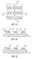
- FIG. 1Ashows a plan view of a structure with two mask layers over a substrate according to an embodiment of the present invention.
- FIG. 1Bshows a schematic first cross-sectional view of the structure of FIG. 1A , taken along lines 1 B- 1 B.
- FIG. 1Cshows a schematic second cross-sectional view of the structure of FIG. 1A , taken along lines 1 C- 1 C.
- FIG. 1Dis a flow chart of an embodiment of the invention.
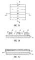
- FIGS. 2A-2Cshow three views of the structure of FIGS. 1A-1C with a first patterned photoresist layer over the two hard mask layers according to an embodiment of the present invention.
- FIGS. 3A-3Cshow three views of the structure of FIGS. 2A-2C with two mask layers after etching through exposed portions of the two hard mask layers according to an embodiment of the present invention.
- FIGS. 4A-4Cshow three views of the structure of FIGS. 3A-3C with a second photoresist layer over remaining portions of two hard mask layers according to an embodiment of the present invention.
- FIGS. 5A-5Cshow three views the structure of FIGS. 4A-4C after etching through exposed portions of the second hard mask layer, according to an embodiment of the present invention.
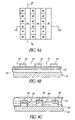
- FIGS. 6A-6Cshow three views of the structure of FIGS. 5A-5C after a first substrate etch step according to an embodiment of the present invention.
- FIGS. 7A-7Cshow three views of the structure of FIGS. 6A-6C after the first mask layer has been removed according to an embodiment of the present invention, forming partial trenches in field isolation regions.
- FIGS. 8A-8Eshow five views of the completed structure after a second substrate etch, resulting in trench regions, active area regions, and pillar regions.
- FIG. 9is a partial isometric view of an array formed using silicon pillars such as those illustrated in FIGS. 8A-8E .
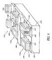
- FIG. 10is a partial isometric view of the structure of FIGS. 8A-8E after filling trench regions and forming a word line connecting neighboring cells.
- a multi-step masking processis used.
- an oxide layer and a nitride layerare used as masks to define trenches, pillars, and intermediate areas in a silicon substrate.
- etch chemistriesare available for etching each of the two mask materials and the substrate relative to the other two materials.
- a first, or lower hard mask layeris formed 70 over bulk silicon.
- a second or upper hard mask layeris then formed 72 over the lower hard mask layer.
- a resist layeris deposited and patterned 74 over the upper hard mask layer to form a first resist mask.
- the exposed portions of the lower and upper hard mask layersare removed 76 and the resist layer is removed 78 .
- the removal of the exposed portions of the lower hard mask layer and the upper hard mask layerexposes corresponding portions of the substrate that will form the trench regions.
- the trench substrate regions, the lower hard mask, and the upper hard maskare arranged in parallel lines.
- a second resist layeris deposited and patterned 80 to form a second resist mask.
- the second resist maskis formed substantially perpendicular to the trench substrate regions and the portions of the remaining lower and upper hard masks.
- the exposed portions of the upper hard maskare removed 82 , and the second resist mask can be removed.
- the trench substrate regions, which were exposed in the pattern of the first resist mask,are then etched 84 . As will be better understood from the detailed description below, this step can be considered a partial trench etch, due to a later extension etch.
- the exposed portions of the lower hard maskare then removed 86 to expose portions of the substrate that will form the intermediate area regions.
- the intermediate regionshave a height that is taller than the trenches but shorter than the pillars.
- the intermediate regionsare used as active areas, bit lines, or for other IC design requirements.
- the partially etched trenchremains exposed.
- the substrateis then etched 88 a second time.
- the second etch processwill etch both the trench substrate regions, which were previously etched, and the intermediate area substrate regions.
- the trenchesare etched to their final depth, and the intermediate area substrate regions are etched to a depth approximately half of the final trench depth. Pillars are thereby formed from the substrate material.
- the two hard maskswill remain over the pillars.
- the hard maskscan be removed or can remain to serve as protective layer for the pillars during subsequent processing.
- the substrateis a semiconductor, more preferably bulk silicon.
- the lower hard maskis an oxide, more preferably silicon oxide.
- the upper hard maskis preferably a nitride, more preferably silicon nitride. When the upper hard mask is silicon nitride, the upper hard mask preferably serves as a cap for subsequent processing.
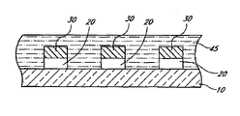
- FIG. 1Ais a top down view at a representative portion of the substrate and shows a surface with a uniform material.
- FIGS. 1B and 1Cshow cross-sections of the substrate 10 with a layer of lower hard mask material 20 and a layer of upper hard mask material 30 .
- the substrate 10is bulk silicon.
- the lower hard mask layer 20is an oxide layer deposited directly over the substrate 10 .
- the oxideis a substantially undoped oxide-deposited by chemical vapor deposition (CVD), spin-on deposition, or other deposition methods.
- the oxidecan also be thermally grown over the surface of the substrate.
- the lower hard mask material 20has a thickness of between about 30 nm and 100 nm, more preferably between about 50 nm and 80 nm.
- the upper hard mask material 30is a nitride layer deposited directly over the lower hard mask material 20 ; more preferably, the upper hard mask material 30 is a silicon nitride layer.
- the upper hard mask layer 30is preferably deposited by CVD or a similar deposition process. In addition to its use as a hard mask, the upper hard mask material 30 can be used to protect the silicon pillar being formed from subsequent processing steps.
- the upper hard mask layer 30has a thickness of between about 50 nm and 150 nm, more preferably between about 80 nm and 120 nm.
- a first resist mask 40is formed over the upper hard mask layer 30 .
- the first resist mask 40is seen in FIGS. 2A-2B .
- a photoresist layer 40is deposited over the upper hard mask 30 , although the skilled artisan will readily appreciate that the mask pattern can be transferred to intervening hard mask materials.
- the photoresist 40can then be selectively exposed and developed to form a first resist mask 40 using, e.g., standard photoresist developing techniques.
- the first resist mask 40can vary in shape and size. The size of the pillar is substantially affected by the wavelength of the photoresist that is being used. Exemplary wavelengths include 248 nm and 193 nm. Advanced micro-masking photolithography techniques, such as phase-shift masks, resist shrinking or growth, and use of spacers, can be used for sub-wavelength lithography.
- this first resist mask 40forms a series of parallel lines over the surface of the upper hard mask layer 30 .
- the first resist mask 40can be used as a mask for an etch process that removes the unmasked portions 42 of the upper hard mask 30 .
- FIGS. 3A-3Cshow the substrate after the removal of the unmasked portions 42 ( FIG. 2B ) of the lower hard mask 20 and the upper hard mask 30 .
- the unmasked portions of the lower hard mask 20can either be removed at the same time as the upper hard mask 30 or in a separate etch step.
- an anisotropic dry etchis used in order to ensure faithful pattern transfer from the photoresist 40 to the upper hard mask 30 and the lower hard mask 20 .
- a fluorine based plasmais used in the dry etch process when the upper mask layer 30 is silicon nitride and the lower hard mask layer 20 is silicon oxide. Skilled practitioners will appreciate that there are several methods of etching the unmasked portions 42 ( FIG.
- a second resist mask 45is formed over the upper hard mask 30 .
- the second resist mask 45forms columns substantially perpendicular to the rows of trench regions 43 and the remaining lower and upper hard mask layers 20 and 30 . This allows for the formation of pillars with substantially rectangular footprints over the substrate. Other shapes are also possible using differing shapes of the first and second resist masks 40 ( FIG. 2B) and 45 .
- FIG. 4Bshows the second resist mask 45 over the upper hard mask 30 .
- FIG. 4Cshows a different cross-section of the substrate, where the resist mask 45 is seen over the trench regions 43 and the remaining lower and upper hard masks 20 and 30 .
- the unmasked portions 47 of the upper hard mask 30 and the lower hard mask 20can eventually form intermediate areas in the substrate 10 .
- FIGS. 5A-5Cshow the substrate after removing the unmasked portions 47 ( FIG. 4B ) of the upper hard mask 30 selective to the lower hard mask 20 and the substrate 10 .
- FIG. 5Bshows a first cross-section of the substrate that illustrates the trench regions 43 of the substrate 10 .
- FIG. 5Cshows a perpendicular cross-section with the lower hard mask 20 extending in rows over the substrate 30 .
- the upper hard mask 30can be seen over portions of the lower hard mask 20 .
- the second resist mask 45is preferably removed after etching the upper hard mask 30 .
- the pillar, trench, and intermediate regionscan be seen in FIG. 5A .
- the upper hard mask 30 and the lower hard mask layer 20are over the regions that will form the pillars.
- the regions with the lower hard mask 20 exposedform the intermediate regions.
- a chlorine based plasmais used in the dry etch process when the upper mask layer 30 is silicon nitride and the lower hard mask layer 20 is silicon oxide and the substrate 10 is silicon. Skilled practitioners will appreciate that there are several methods to etch preferred materials for the upper hard mask 30 selectively against preferred materials for the lower hard mask 20 and the substrate 10 .
- FIGS. 6A-6Cillustrate the product of a first substrate etch.
- the etch processetches the substrate material 10 but is selective against the upper hard mask 30 and the lower hard mask 20 .
- the first substrate etch processremoves between about 250 nm and 450 nm, more preferably between about 300 nm and 400 nm.
- the lower hard mask 20acts as a hard mask for the first substrate etch, so only the trench regions 43 ( FIG. 5A ) will be etched to form an intermediate trench 50 .
- FIG. 6Bshows the pillar regions 65 with the upper hard mask 30 and the lower hard mask 20 stacks over the substrate 10 .
- FIG. 6Cis identical to FIG.
- the lower hard mask 20acts as a mask to the substrate etch, such that substrate 10 is not etched in regions under the lines of the lower hard mask 20 .
- a chlorine based plasmais used in the dry etch process when the upper mask layer 30 is silicon nitride and the lower hard mask layer 20 is silicon oxide and the substrate 10 is silicon. Skilled practitioners will appreciate that several methods can be used to etch the substrate.
- FIGS. 7A-7Cillustrate the removal of the portions of the lower hard mask 20 not covered by the upper hard mask 30 . This will expose the intermediate regions 52 of the substrate 10 . While these regions 52 are preferably used as active areas, the skilled practitioner will appreciate that the active areas could also be formed on the pillars 65 . Additionally, the intermediate regions 52 could also be used for other purposes, such as a bit line. At this point, only the pillar regions 65 ( FIG. 7B ) are covered by the lower hard mask 20 and the upper hard mask 30 . At this stage of the process, the lower and upper hard masks 20 and 30 are now unconnected islands. The cross-section of FIG. 7B appears identical to FIG.
- FIG. 7Cillustrates a cross-section which shows substrate 10 regions 52 that will become the intermediate regions, which are now exposed, and the regions 65 that will become the pillars, which are capped by the oxide 20 and nitride 30 stack.
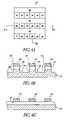
- FIGS. 8A-8Eillustrate the product of a second substrate etch and the completion of the formation of the silicon pillars.
- the second substrate etch processremoves between about 200 nm and 400 nm, more preferably between about 250 nm and 350 nm of the substrate 10 .
- the trench regions 55will be etched to a depth between about 450 nm and 850 nm below the pillar regions 65 , more preferably between about 550 nm and 750 nm.
- the second substrate etch processis selective to the upper hard mask 30 and the lower hard mask 20 .
- a chlorine based plasma etch processcan be used in the second substrate etch step. Skilled practitioners will appreciate that several methods can be used to etch the substrate selectively against the nitride mask.
- FIG. 8Ashows a plan view illustrating the three regions.
- the trenches 55have been etched to their final depth, and the intermediate regions 60 have been etched.
- the trenches 55have been exposed to both etch steps.
- the intermediate regions 60have been exposed to one etch step.
- the upper hard mask 30 and the lower hard mask 20remain over the pillars 65 .
- the pillars 65have not been exposed to either etch step.
- the upper hard mask 30 and the lower hard mask 20can be seen over the pillars 65 in FIG. 8B , a cross-sectional view.
- the pillars 65 , and the two hard masks 20 and 30can be seen next to the intermediate regions 60 , which are formed in rows within shallow trenches between pillars 65 . The rows are elevated relative to the deeper trenches 55 , as best seen from FIG. 8D .
- a trench 55can be seen in cross-section.
- the pillars 65 , intermediate regions 60 , and two hard masks 20 and 30can be seen in relief behind the trench 55 .
- the intermediate regions 60can be seen beside the trenches 55 .
- the pillars 65 and the hard masks 20 and 30can be seen in relief behind the intermediate regions 60 .
- the deepest levelwill be the trench region 55 , as it will have been exposed to two substrate etch steps.
- the intermediate regions 60will have been masked by the lower hard mask 20 during the first substrate etch step.
- the silicon pillars 65will have not been exposed to either etch step and will still be capped by the oxide 20 and nitride 30 stack.
- the second substrate etch stepetches the substrate to an approximately equal depth as the depth of the first substrate etch.
- the silicon pillars 65are shown in cross-section next to the trenches 55 .
- the silicon pillarsare still capped by the oxide 20 and nitride 30 stack, and therefore have not been exposed to either substrate etch.
- the silicon pillars 65are next to the intermediate regions 60 , which have been exposed to one substrate etch step.
- FIG. 8Dis a. cross section from within a trench region 55 . The other regions appear in surface shading behind the trench substrate region 55 . A layer of substrate material which forms the intermediate regions 60 and the silicon pillars 65 is seen over the trench region.
- the pillar region 65is capped by the oxide 20 and nitride 30 stack. In the illustrated embodiment, measured from the floor of the trench region 55 , the pillar region 65 is approximately twice as tall as the intermediate regions 60 . This can also be seen from FIG. 8E which shows a cross-section through the intermediate regions 60 and the trench regions 55 . The silicon pillars 65 , which can be seen behind the intermediate regions 60 , are approximately twice as tall as the intermediate regions 60 .
- the intermediate, or “active area” regions 60are used to form the active area for a transistor.
- the “active area” regions 60may also be used for other purposes, such as forming a bit line, as seen in FIG. 9 .
- FIGS. 1-8A skilled artisan can appreciate that the structure formed by the process illustrated in FIGS. 1-8 can be-used to form several types of structures through subsequent processing.
- FIG. 9an exemplary memory array using silicon pillars, such as those created by the process described above, is illustrated.
- Transistors formed using silicon pillarsare described in U.S. Pat. No. 6,492,233 which was issued to Forbes, et al, on Dec. 10, 2002. The disclosure of the Forbes patent is incorporated by reference herein.
- FIG. 9is a perspective view illustrating generally one embodiment of a portion of a memory according to the present invention.
- FIG. 9illustrates portions of six memory cells 112 a - f including portions of vertically oriented access FETs 130 therein.
- Conductive segments of bit lines 202represent particular ones of bit lines in the array.
- Conductive segments of word line 206represents any one of the word lines in the array, which provide integrally formed gate regions for access FETs 130 between which the particular word line 206 is interposed.
- Conductive segments of body line 208represents any one of body lines in the array, which provide interconnected electrical body contacts to body regions of access FETs 130 between which the particular body line 208 is interposed.
- the word lines, e.g. word line 206 , and the body lines, e.g. body line 208are alternatingly disposed (interdigitated) within the array 110 .
- memory cell 112refers only to memory cells 112 a - f , the bit lines 202 , the word line 206 , and the body line 208 that are associated with memory cells 112 a - f . However, the following description similarly applies to all memory cells 112 and similar conductive lines in a larger array.
- vertically oriented access FETs 130are formed in semiconductor pillars that extend outwardly from an underlying substrate 210 .
- the substrate 210can be bulk semiconductor starting material, semiconductor-on-insulator (SOI) starting material, or SOI material that is formed from a bulk semiconductor starting material during processing.
- SOIsemiconductor-on-insulator
- access FETs 130includes first source/drain regions 212 of the access FETs 130 formed on the bulk silicon substrate 210 and integrally formed n++ conductively doped bit lines 202 .
- the bit lines 202define a particular row of memory cells 112 .
- a body region 214 of access FET 130is formed on the n+ first source/drain region 212 .
- Inversion channelsmay be capacitively generated at the sidewalls of the body region 214 of the semiconductor pillar under the control of word line 206 .
- the word line 206includes the gate region of adjacent access FETs, 130 .
- a second source/drain region 216 of access FET 130is formed on p-body region 214 .
- Storage capacitors 132are formed on the second/source drain regions 216 .
- the substrateis grown epitaxially before the processing steps of FIGS. 1-8 .
- transistorscan also be formed from silicon pillars formed from a bulk silicon substrate. Additionally, while doping steps are not specifically described, a skilled artisan will understand the doping processes of these silicon materials.
- Word lines 206 and body lines 208are alternatingly disposed (interdigitated) within the array. For example, one of the word lines 206 is interposed between each semiconductor pillar of memory cell pairs 112 a - b and 112 d - e . Body line 208 is interposed between semiconductor pillars of memory cell pairs 112 b - c and 112 e - f .
- access FETs 130are formed on bit lines 202 in semiconductor pillars extending outwardly from substrate 210 .
- Such semiconductor pillarsinclude body regions 214 , and first and second source drain regions 212 and 216 , respectively.
- the bit lines 202contact the bulk semiconductor substrate 210
- the body lines 208contact body regions 214 of adjacent access FETs 130 .
- the memory of FIG. 9is merely an exemplary embodiment of transistors formed using silicon pillars.
- the silicon pillarscan be used to form several different types of vertical transistors.
- the trenches 55are filled with an insulating material 70 , preferably an oxide.
- the insulating material 70is recessed to a height approximately equal to the height of the active areas 60 .
- the pillar 65is preferably oxidized to form a gate dielectric for the vertical transistor.
- Word lines 75are preferably formed perpendicularly to the insulating material 70 .
- the word linessurround the pillars 65 and connect a row of vertical transistors formed in the array 100 . Although only one word line 75 is shown in FIG. 10 , preferably there will be a plurality of parallel word lines in the array 100 .
- silicon pillarshave a wide variety of uses in semiconductor fabrication, especially with respect to transistor formation.
- etching materialsat other stages of integrated circuit fabrication.
- Materials selected for the substrate 10 , the lower hard mask 20 , and the upper hard mask 30can be varied for other uses. Particularly, the principles described herein will improve the etching process when a structure needs to be etched to varying depths in different regions.
- the pillars 65can be useful in other contexts such as memory cell capacitors, in trenches for hybrid shallow trench isolation (STI) and LOCal Oxidation of Silicon (LOCOS) isolation schemes, and for many other purposes.
- STIshallow trench isolation
- LOCOSLOCal Oxidation of Silicon
Landscapes
- Engineering & Computer Science (AREA)
- Physics & Mathematics (AREA)
- Manufacturing & Machinery (AREA)
- Condensed Matter Physics & Semiconductors (AREA)
- General Physics & Mathematics (AREA)
- Computer Hardware Design (AREA)
- Microelectronics & Electronic Packaging (AREA)
- Power Engineering (AREA)
- Plasma & Fusion (AREA)
- Semiconductor Memories (AREA)
Abstract
Description
Claims (15)
Priority Applications (5)
| Application Number | Priority Date | Filing Date | Title |
|---|---|---|---|
| US11/683,122US7723756B2 (en) | 2004-08-19 | 2007-03-07 | Silicon pillars for vertical transistors |
| US12/783,462US8026579B2 (en) | 2004-08-19 | 2010-05-19 | Silicon pillars for vertical transistors |
| US13/227,187US8330246B2 (en) | 2004-08-19 | 2011-09-07 | Intermediate structures for forming circuits |
| US13/670,209US8629533B2 (en) | 2004-08-19 | 2012-11-06 | Pillars for vertical transistors |
| US14/106,372US8847298B2 (en) | 2004-08-19 | 2013-12-13 | Pillars for vertical transistors |
Applications Claiming Priority (2)
| Application Number | Priority Date | Filing Date | Title |
|---|---|---|---|
| US10/922,583US7247570B2 (en) | 2004-08-19 | 2004-08-19 | Silicon pillars for vertical transistors |
| US11/683,122US7723756B2 (en) | 2004-08-19 | 2007-03-07 | Silicon pillars for vertical transistors |
Related Parent Applications (1)
| Application Number | Title | Priority Date | Filing Date |
|---|---|---|---|
| US10/922,583DivisionUS7247570B2 (en) | 2004-08-19 | 2004-08-19 | Silicon pillars for vertical transistors |
Related Child Applications (1)
| Application Number | Title | Priority Date | Filing Date |
|---|---|---|---|
| US12/783,462DivisionUS8026579B2 (en) | 2004-08-19 | 2010-05-19 | Silicon pillars for vertical transistors |
Publications (2)
| Publication Number | Publication Date |
|---|---|
| US20070164319A1 US20070164319A1 (en) | 2007-07-19 |
| US7723756B2true US7723756B2 (en) | 2010-05-25 |
Family
ID=35908867
Family Applications (7)
| Application Number | Title | Priority Date | Filing Date |
|---|---|---|---|
| US10/922,583Expired - LifetimeUS7247570B2 (en) | 2004-08-19 | 2004-08-19 | Silicon pillars for vertical transistors |
| US11/494,420Expired - LifetimeUS7413480B2 (en) | 2004-08-19 | 2006-07-27 | Silicon pillars for vertical transistors |
| US11/683,122Expired - LifetimeUS7723756B2 (en) | 2004-08-19 | 2007-03-07 | Silicon pillars for vertical transistors |
| US12/783,462Expired - LifetimeUS8026579B2 (en) | 2004-08-19 | 2010-05-19 | Silicon pillars for vertical transistors |
| US13/227,187Expired - LifetimeUS8330246B2 (en) | 2004-08-19 | 2011-09-07 | Intermediate structures for forming circuits |
| US13/670,209Expired - LifetimeUS8629533B2 (en) | 2004-08-19 | 2012-11-06 | Pillars for vertical transistors |
| US14/106,372Expired - LifetimeUS8847298B2 (en) | 2004-08-19 | 2013-12-13 | Pillars for vertical transistors |
Family Applications Before (2)
| Application Number | Title | Priority Date | Filing Date |
|---|---|---|---|
| US10/922,583Expired - LifetimeUS7247570B2 (en) | 2004-08-19 | 2004-08-19 | Silicon pillars for vertical transistors |
| US11/494,420Expired - LifetimeUS7413480B2 (en) | 2004-08-19 | 2006-07-27 | Silicon pillars for vertical transistors |
Family Applications After (4)
| Application Number | Title | Priority Date | Filing Date |
|---|---|---|---|
| US12/783,462Expired - LifetimeUS8026579B2 (en) | 2004-08-19 | 2010-05-19 | Silicon pillars for vertical transistors |
| US13/227,187Expired - LifetimeUS8330246B2 (en) | 2004-08-19 | 2011-09-07 | Intermediate structures for forming circuits |
| US13/670,209Expired - LifetimeUS8629533B2 (en) | 2004-08-19 | 2012-11-06 | Pillars for vertical transistors |
| US14/106,372Expired - LifetimeUS8847298B2 (en) | 2004-08-19 | 2013-12-13 | Pillars for vertical transistors |
Country Status (1)
| Country | Link |
|---|---|
| US (7) | US7247570B2 (en) |
Cited By (5)
| Publication number | Priority date | Publication date | Assignee | Title |
|---|---|---|---|---|
| US8115243B2 (en) | 2005-07-06 | 2012-02-14 | Micron Technology, Inc. | Surround gate access transistors with grown ultra-thin bodies |
| US8772782B2 (en) | 2011-11-23 | 2014-07-08 | International Business Machines Corporation | Transistor employing vertically stacked self-aligned carbon nanotubes |
| US8847298B2 (en) | 2004-08-19 | 2014-09-30 | Micron Technology, Inc. | Pillars for vertical transistors |
| US10461173B1 (en) | 2018-05-25 | 2019-10-29 | Globalfoundries Inc. | Methods, apparatus, and manufacturing system for forming source and drain regions in a vertical field effect transistor |
| US10522686B2 (en) | 2017-09-26 | 2019-12-31 | International Business Machines Corporation | Vertical thin film transistor |
Families Citing this family (163)
| Publication number | Priority date | Publication date | Assignee | Title |
|---|---|---|---|---|
| US7768051B2 (en) | 2005-07-25 | 2010-08-03 | Micron Technology, Inc. | DRAM including a vertical surround gate transistor |
| KR100817074B1 (en)* | 2006-11-08 | 2008-03-26 | 삼성전자주식회사 | Semiconductor device having fin-type active region and method of manufacturing same |
| DE102006054545A1 (en)* | 2006-11-20 | 2008-05-21 | Qimonda Ag | Hard mask layer structuring method, involves creating structures in resist layers, respectively, transferring structures into hard mask layer in single etching step, and forming hard mask |
| US8183628B2 (en) | 2007-10-29 | 2012-05-22 | Unisantis Electronics Singapore Pte Ltd. | Semiconductor structure and method of fabricating the semiconductor structure |
| US8207028B2 (en)* | 2008-01-22 | 2012-06-26 | International Business Machines Corporation | Two-dimensional patterning employing self-assembled material |
| JP5317343B2 (en)* | 2009-04-28 | 2013-10-16 | ユニサンティス エレクトロニクス シンガポール プライベート リミテッド | Semiconductor device and manufacturing method thereof |
| US8598650B2 (en) | 2008-01-29 | 2013-12-03 | Unisantis Electronics Singapore Pte Ltd. | Semiconductor device and production method therefor |
| US8212298B2 (en)* | 2008-01-29 | 2012-07-03 | Unisantis Electronics Singapore Pte Ltd. | Semiconductor storage device and methods of producing it |
| US8030215B1 (en) | 2008-02-19 | 2011-10-04 | Marvell International Ltd. | Method for creating ultra-high-density holes and metallization |
| KR100971412B1 (en)* | 2008-05-21 | 2010-07-21 | 주식회사 하이닉스반도체 | Method of forming vertical channel transistor in semiconductor device |
| US7974119B2 (en) | 2008-07-10 | 2011-07-05 | Seagate Technology Llc | Transmission gate-based spin-transfer torque memory unit |
| US7979836B2 (en)* | 2008-08-15 | 2011-07-12 | International Business Machines Corporation | Split-gate DRAM with MuGFET, design structure, and method of manufacture |
| US7781283B2 (en)* | 2008-08-15 | 2010-08-24 | International Business Machines Corporation | Split-gate DRAM with MuGFET, design structure, and method of manufacture |
| US9030867B2 (en) | 2008-10-20 | 2015-05-12 | Seagate Technology Llc | Bipolar CMOS select device for resistive sense memory |
| US7936580B2 (en) | 2008-10-20 | 2011-05-03 | Seagate Technology Llc | MRAM diode array and access method |
| US7936583B2 (en) | 2008-10-30 | 2011-05-03 | Seagate Technology Llc | Variable resistive memory punchthrough access method |
| US7825478B2 (en)* | 2008-11-07 | 2010-11-02 | Seagate Technology Llc | Polarity dependent switch for resistive sense memory |
| US8178864B2 (en) | 2008-11-18 | 2012-05-15 | Seagate Technology Llc | Asymmetric barrier diode |
| US8203869B2 (en) | 2008-12-02 | 2012-06-19 | Seagate Technology Llc | Bit line charge accumulation sensing for resistive changing memory |
| US8184472B2 (en)* | 2009-03-13 | 2012-05-22 | International Business Machines Corporation | Split-gate DRAM with lateral control-gate MuGFET |
| US7999332B2 (en)* | 2009-05-14 | 2011-08-16 | International Business Machines Corporation | Asymmetric semiconductor devices and method of fabricating |
| US8159856B2 (en) | 2009-07-07 | 2012-04-17 | Seagate Technology Llc | Bipolar select device for resistive sense memory |
| US8158964B2 (en) | 2009-07-13 | 2012-04-17 | Seagate Technology Llc | Schottky diode switch and memory units containing the same |
| JP5356970B2 (en)* | 2009-10-01 | 2013-12-04 | ユニサンティス エレクトロニクス シンガポール プライベート リミテッド | Semiconductor device |
| JP4912513B2 (en)* | 2010-03-08 | 2012-04-11 | ユニサンティス エレクトロニクス シンガポール プライベート リミテッド | Solid-state imaging device |
| US8487357B2 (en) | 2010-03-12 | 2013-07-16 | Unisantis Electronics Singapore Pte Ltd. | Solid state imaging device having high sensitivity and high pixel density |
| US9324576B2 (en) | 2010-05-27 | 2016-04-26 | Applied Materials, Inc. | Selective etch for silicon films |
| JP5066590B2 (en) | 2010-06-09 | 2012-11-07 | ユニサンティス エレクトロニクス シンガポール プライベート リミテッド | Semiconductor device and manufacturing method thereof |
| JP5087655B2 (en) | 2010-06-15 | 2012-12-05 | ユニサンティス エレクトロニクス シンガポール プライベート リミテッド | Semiconductor device and manufacturing method thereof |
| US8617952B2 (en) | 2010-09-28 | 2013-12-31 | Seagate Technology Llc | Vertical transistor with hardening implatation |
| US8648426B2 (en) | 2010-12-17 | 2014-02-11 | Seagate Technology Llc | Tunneling transistors |
| US10283321B2 (en) | 2011-01-18 | 2019-05-07 | Applied Materials, Inc. | Semiconductor processing system and methods using capacitively coupled plasma |
| US9064815B2 (en) | 2011-03-14 | 2015-06-23 | Applied Materials, Inc. | Methods for etch of metal and metal-oxide films |
| US8999856B2 (en) | 2011-03-14 | 2015-04-07 | Applied Materials, Inc. | Methods for etch of sin films |
| US8697522B2 (en) | 2011-07-05 | 2014-04-15 | International Business Machines Corporation | Bulk finFET with uniform height and bottom isolation |
| US8564034B2 (en) | 2011-09-08 | 2013-10-22 | Unisantis Electronics Singapore Pte. Ltd. | Solid-state imaging device |
| US8669601B2 (en) | 2011-09-15 | 2014-03-11 | Unisantis Electronics Singapore Pte. Ltd. | Method for producing semiconductor device and semiconductor device having pillar-shaped semiconductor |
| US8437184B1 (en)* | 2011-12-06 | 2013-05-07 | Rexchip Electronics Corporation | Method of controlling a vertical dual-gate dynamic random access memory |
| US8772175B2 (en) | 2011-12-19 | 2014-07-08 | Unisantis Electronics Singapore Pte. Ltd. | Method for manufacturing semiconductor device and semiconductor device |
| US8916478B2 (en) | 2011-12-19 | 2014-12-23 | Unisantis Electronics Singapore Pte. Ltd. | Method for manufacturing semiconductor device and semiconductor device |
| US20130193400A1 (en)* | 2012-01-27 | 2013-08-01 | Micron Technology, Inc. | Memory Cell Structures and Memory Arrays |
| US8748938B2 (en) | 2012-02-20 | 2014-06-10 | Unisantis Electronics Singapore Pte. Ltd. | Solid-state imaging device |
| US9267739B2 (en) | 2012-07-18 | 2016-02-23 | Applied Materials, Inc. | Pedestal with multi-zone temperature control and multiple purge capabilities |
| US9373517B2 (en) | 2012-08-02 | 2016-06-21 | Applied Materials, Inc. | Semiconductor processing with DC assisted RF power for improved control |
| US9064745B2 (en) | 2012-08-29 | 2015-06-23 | International Business Machines Corporation | Sublithographic width finFET employing solid phase epitaxy |
| US9132436B2 (en) | 2012-09-21 | 2015-09-15 | Applied Materials, Inc. | Chemical control features in wafer process equipment |
| US10256079B2 (en) | 2013-02-08 | 2019-04-09 | Applied Materials, Inc. | Semiconductor processing systems having multiple plasma configurations |
| US9362130B2 (en) | 2013-03-01 | 2016-06-07 | Applied Materials, Inc. | Enhanced etching processes using remote plasma sources |
| US9040422B2 (en) | 2013-03-05 | 2015-05-26 | Applied Materials, Inc. | Selective titanium nitride removal |
| US8901529B2 (en)* | 2013-03-15 | 2014-12-02 | International Business Machines Corporation | Memory array with self-aligned epitaxially grown memory elements and annular FET |
| US20140271097A1 (en) | 2013-03-15 | 2014-09-18 | Applied Materials, Inc. | Processing systems and methods for halide scavenging |
| US9493879B2 (en) | 2013-07-12 | 2016-11-15 | Applied Materials, Inc. | Selective sputtering for pattern transfer |
| US9773648B2 (en) | 2013-08-30 | 2017-09-26 | Applied Materials, Inc. | Dual discharge modes operation for remote plasma |
| US9576809B2 (en) | 2013-11-04 | 2017-02-21 | Applied Materials, Inc. | Etch suppression with germanium |
| US9520303B2 (en) | 2013-11-12 | 2016-12-13 | Applied Materials, Inc. | Aluminum selective etch |
| US9245762B2 (en) | 2013-12-02 | 2016-01-26 | Applied Materials, Inc. | Procedure for etch rate consistency |
| US9499898B2 (en) | 2014-03-03 | 2016-11-22 | Applied Materials, Inc. | Layered thin film heater and method of fabrication |
| US9299537B2 (en) | 2014-03-20 | 2016-03-29 | Applied Materials, Inc. | Radial waveguide systems and methods for post-match control of microwaves |
| US9903020B2 (en) | 2014-03-31 | 2018-02-27 | Applied Materials, Inc. | Generation of compact alumina passivation layers on aluminum plasma equipment components |
| US9309598B2 (en) | 2014-05-28 | 2016-04-12 | Applied Materials, Inc. | Oxide and metal removal |
| US9425058B2 (en)* | 2014-07-24 | 2016-08-23 | Applied Materials, Inc. | Simplified litho-etch-litho-etch process |
| US9496167B2 (en) | 2014-07-31 | 2016-11-15 | Applied Materials, Inc. | Integrated bit-line airgap formation and gate stack post clean |
| US9659753B2 (en) | 2014-08-07 | 2017-05-23 | Applied Materials, Inc. | Grooved insulator to reduce leakage current |
| US9553102B2 (en) | 2014-08-19 | 2017-01-24 | Applied Materials, Inc. | Tungsten separation |
| US9355862B2 (en) | 2014-09-24 | 2016-05-31 | Applied Materials, Inc. | Fluorine-based hardmask removal |
| US9613822B2 (en) | 2014-09-25 | 2017-04-04 | Applied Materials, Inc. | Oxide etch selectivity enhancement |
| US9966240B2 (en) | 2014-10-14 | 2018-05-08 | Applied Materials, Inc. | Systems and methods for internal surface conditioning assessment in plasma processing equipment |
| US9355922B2 (en) | 2014-10-14 | 2016-05-31 | Applied Materials, Inc. | Systems and methods for internal surface conditioning in plasma processing equipment |
| US11637002B2 (en) | 2014-11-26 | 2023-04-25 | Applied Materials, Inc. | Methods and systems to enhance process uniformity |
| US10573496B2 (en) | 2014-12-09 | 2020-02-25 | Applied Materials, Inc. | Direct outlet toroidal plasma source |
| US10224210B2 (en) | 2014-12-09 | 2019-03-05 | Applied Materials, Inc. | Plasma processing system with direct outlet toroidal plasma source |
| US9502258B2 (en) | 2014-12-23 | 2016-11-22 | Applied Materials, Inc. | Anisotropic gap etch |
| US11257693B2 (en) | 2015-01-09 | 2022-02-22 | Applied Materials, Inc. | Methods and systems to improve pedestal temperature control |
| KR102315527B1 (en) | 2015-01-19 | 2021-10-22 | 삼성디스플레이 주식회사 | Thin film transistor substrate and method of manufacturing a thin film transistor substrate |
| US20160225652A1 (en) | 2015-02-03 | 2016-08-04 | Applied Materials, Inc. | Low temperature chuck for plasma processing systems |
| US9728437B2 (en) | 2015-02-03 | 2017-08-08 | Applied Materials, Inc. | High temperature chuck for plasma processing systems |
| US9881805B2 (en) | 2015-03-02 | 2018-01-30 | Applied Materials, Inc. | Silicon selective removal |
| US9741593B2 (en) | 2015-08-06 | 2017-08-22 | Applied Materials, Inc. | Thermal management systems and methods for wafer processing systems |
| US9691645B2 (en) | 2015-08-06 | 2017-06-27 | Applied Materials, Inc. | Bolted wafer chuck thermal management systems and methods for wafer processing systems |
| US9349605B1 (en) | 2015-08-07 | 2016-05-24 | Applied Materials, Inc. | Oxide etch selectivity systems and methods |
| US10504700B2 (en) | 2015-08-27 | 2019-12-10 | Applied Materials, Inc. | Plasma etching systems and methods with secondary plasma injection |
| KR102427133B1 (en) | 2015-08-31 | 2022-08-01 | 삼성전자주식회사 | Semiconductor device and method of fabricating the same |
| US9620509B1 (en)* | 2015-10-30 | 2017-04-11 | Taiwan Semiconductor Manufacturing Co., Ltd. | Static random access memory device with vertical FET devices |
| US9818623B2 (en) | 2016-03-22 | 2017-11-14 | Globalfoundries Inc. | Method of forming a pattern for interconnection lines and associated continuity blocks in an integrated circuit |
| US9607899B1 (en) | 2016-04-27 | 2017-03-28 | International Business Machines Corporation | Integration of vertical transistors with 3D long channel transistors |
| US10522371B2 (en) | 2016-05-19 | 2019-12-31 | Applied Materials, Inc. | Systems and methods for improved semiconductor etching and component protection |
| US10504754B2 (en) | 2016-05-19 | 2019-12-10 | Applied Materials, Inc. | Systems and methods for improved semiconductor etching and component protection |
| US9905663B2 (en) | 2016-06-24 | 2018-02-27 | International Business Machines Corporation | Fabrication of a vertical fin field effect transistor with a reduced contact resistance |
| US9865484B1 (en) | 2016-06-29 | 2018-01-09 | Applied Materials, Inc. | Selective etch using material modification and RF pulsing |
| KR102549609B1 (en) | 2016-09-08 | 2023-06-30 | 삼성전자주식회사 | Semiconductor devices including a vertical channel transistor |
| US10062575B2 (en) | 2016-09-09 | 2018-08-28 | Applied Materials, Inc. | Poly directional etch by oxidation |
| US10629473B2 (en) | 2016-09-09 | 2020-04-21 | Applied Materials, Inc. | Footing removal for nitride spacer |
| US9818641B1 (en) | 2016-09-21 | 2017-11-14 | Globalfoundries Inc. | Apparatus and method of forming self-aligned cuts in mandrel and a non-mandrel lines of an array of metal lines |
| US9818640B1 (en) | 2016-09-21 | 2017-11-14 | Globalfoundries Inc. | Apparatus and method of forming self-aligned cuts in a non-mandrel line of an array of metal lines |
| US9647112B1 (en)* | 2016-09-22 | 2017-05-09 | International Business Machines Corporation | Fabrication of strained vertical P-type field effect transistors by bottom condensation |
| US9721789B1 (en) | 2016-10-04 | 2017-08-01 | Applied Materials, Inc. | Saving ion-damaged spacers |
| US10062585B2 (en) | 2016-10-04 | 2018-08-28 | Applied Materials, Inc. | Oxygen compatible plasma source |
| US9934942B1 (en) | 2016-10-04 | 2018-04-03 | Applied Materials, Inc. | Chamber with flow-through source |
| US10546729B2 (en) | 2016-10-04 | 2020-01-28 | Applied Materials, Inc. | Dual-channel showerhead with improved profile |
| US10062579B2 (en) | 2016-10-07 | 2018-08-28 | Applied Materials, Inc. | Selective SiN lateral recess |
| US9947549B1 (en) | 2016-10-10 | 2018-04-17 | Applied Materials, Inc. | Cobalt-containing material removal |
| JP6393841B2 (en)* | 2016-10-14 | 2018-09-19 | ユニサンティス エレクトロニクス シンガポール プライベート リミテッドUnisantis Electronics Singapore Pte Ltd. | Method for manufacturing columnar semiconductor device |
| US9768034B1 (en) | 2016-11-11 | 2017-09-19 | Applied Materials, Inc. | Removal methods for high aspect ratio structures |
| US10163696B2 (en) | 2016-11-11 | 2018-12-25 | Applied Materials, Inc. | Selective cobalt removal for bottom up gapfill |
| US10026621B2 (en) | 2016-11-14 | 2018-07-17 | Applied Materials, Inc. | SiN spacer profile patterning |
| US10242908B2 (en) | 2016-11-14 | 2019-03-26 | Applied Materials, Inc. | Airgap formation with damage-free copper |
| US9852986B1 (en)* | 2016-11-28 | 2017-12-26 | Globalfoundries Inc. | Method of patterning pillars to form variable continuity cuts in interconnection lines of an integrated circuit |
| US9887127B1 (en) | 2016-12-15 | 2018-02-06 | Globalfoundries Inc. | Interconnection lines having variable widths and partially self-aligned continuity cuts |
| US9812351B1 (en) | 2016-12-15 | 2017-11-07 | Globalfoundries Inc. | Interconnection cells having variable width metal lines and fully-self aligned continuity cuts |
| US10043703B2 (en) | 2016-12-15 | 2018-08-07 | Globalfoundries Inc. | Apparatus and method for forming interconnection lines having variable pitch and variable widths |
| US10002786B1 (en) | 2016-12-15 | 2018-06-19 | Globalfoundries Inc. | Interconnection cells having variable width metal lines and fully-self aligned variable length continuity cuts |
| US10566206B2 (en) | 2016-12-27 | 2020-02-18 | Applied Materials, Inc. | Systems and methods for anisotropic material breakthrough |
| US10431429B2 (en) | 2017-02-03 | 2019-10-01 | Applied Materials, Inc. | Systems and methods for radial and azimuthal control of plasma uniformity |
| US10403507B2 (en) | 2017-02-03 | 2019-09-03 | Applied Materials, Inc. | Shaped etch profile with oxidation |
| US10043684B1 (en) | 2017-02-06 | 2018-08-07 | Applied Materials, Inc. | Self-limiting atomic thermal etching systems and methods |
| US10319739B2 (en) | 2017-02-08 | 2019-06-11 | Applied Materials, Inc. | Accommodating imperfectly aligned memory holes |
| US10943834B2 (en) | 2017-03-13 | 2021-03-09 | Applied Materials, Inc. | Replacement contact process |
| US10319649B2 (en) | 2017-04-11 | 2019-06-11 | Applied Materials, Inc. | Optical emission spectroscopy (OES) for remote plasma monitoring |
| US11276590B2 (en) | 2017-05-17 | 2022-03-15 | Applied Materials, Inc. | Multi-zone semiconductor substrate supports |
| JP7176860B6 (en) | 2017-05-17 | 2022-12-16 | アプライド マテリアルズ インコーポレイテッド | Semiconductor processing chamber to improve precursor flow |
| US11276559B2 (en) | 2017-05-17 | 2022-03-15 | Applied Materials, Inc. | Semiconductor processing chamber for multiple precursor flow |
| US10049891B1 (en) | 2017-05-31 | 2018-08-14 | Applied Materials, Inc. | Selective in situ cobalt residue removal |
| US10497579B2 (en) | 2017-05-31 | 2019-12-03 | Applied Materials, Inc. | Water-free etching methods |
| US10920320B2 (en) | 2017-06-16 | 2021-02-16 | Applied Materials, Inc. | Plasma health determination in semiconductor substrate processing reactors |
| WO2019005218A1 (en) | 2017-06-26 | 2019-01-03 | Micron Technology, Inc. | Apparatuses having body connection lines coupled with access devices |
| US10541246B2 (en) | 2017-06-26 | 2020-01-21 | Applied Materials, Inc. | 3D flash memory cells which discourage cross-cell electrical tunneling |
| US10727080B2 (en) | 2017-07-07 | 2020-07-28 | Applied Materials, Inc. | Tantalum-containing material removal |
| US10541184B2 (en) | 2017-07-11 | 2020-01-21 | Applied Materials, Inc. | Optical emission spectroscopic techniques for monitoring etching |
| US10354889B2 (en) | 2017-07-17 | 2019-07-16 | Applied Materials, Inc. | Non-halogen etching of silicon-containing materials |
| US10043674B1 (en) | 2017-08-04 | 2018-08-07 | Applied Materials, Inc. | Germanium etching systems and methods |
| US10170336B1 (en) | 2017-08-04 | 2019-01-01 | Applied Materials, Inc. | Methods for anisotropic control of selective silicon removal |
| US10297458B2 (en) | 2017-08-07 | 2019-05-21 | Applied Materials, Inc. | Process window widening using coated parts in plasma etch processes |
| US10283324B1 (en) | 2017-10-24 | 2019-05-07 | Applied Materials, Inc. | Oxygen treatment for nitride etching |
| US10128086B1 (en) | 2017-10-24 | 2018-11-13 | Applied Materials, Inc. | Silicon pretreatment for nitride removal |
| US10256112B1 (en) | 2017-12-08 | 2019-04-09 | Applied Materials, Inc. | Selective tungsten removal |
| US10903054B2 (en) | 2017-12-19 | 2021-01-26 | Applied Materials, Inc. | Multi-zone gas distribution systems and methods |
| US11328909B2 (en) | 2017-12-22 | 2022-05-10 | Applied Materials, Inc. | Chamber conditioning and removal processes |
| US10854426B2 (en) | 2018-01-08 | 2020-12-01 | Applied Materials, Inc. | Metal recess for semiconductor structures |
| US10964512B2 (en) | 2018-02-15 | 2021-03-30 | Applied Materials, Inc. | Semiconductor processing chamber multistage mixing apparatus and methods |
| US10679870B2 (en) | 2018-02-15 | 2020-06-09 | Applied Materials, Inc. | Semiconductor processing chamber multistage mixing apparatus |
| TWI766433B (en) | 2018-02-28 | 2022-06-01 | 美商應用材料股份有限公司 | Systems and methods to form airgaps |
| US10593560B2 (en) | 2018-03-01 | 2020-03-17 | Applied Materials, Inc. | Magnetic induction plasma source for semiconductor processes and equipment |
| US10319600B1 (en) | 2018-03-12 | 2019-06-11 | Applied Materials, Inc. | Thermal silicon etch |
| US10497573B2 (en) | 2018-03-13 | 2019-12-03 | Applied Materials, Inc. | Selective atomic layer etching of semiconductor materials |
| US10573527B2 (en) | 2018-04-06 | 2020-02-25 | Applied Materials, Inc. | Gas-phase selective etching systems and methods |
| US10490406B2 (en) | 2018-04-10 | 2019-11-26 | Appled Materials, Inc. | Systems and methods for material breakthrough |
| US10699879B2 (en) | 2018-04-17 | 2020-06-30 | Applied Materials, Inc. | Two piece electrode assembly with gap for plasma control |
| US10886137B2 (en) | 2018-04-30 | 2021-01-05 | Applied Materials, Inc. | Selective nitride removal |
| US10755941B2 (en) | 2018-07-06 | 2020-08-25 | Applied Materials, Inc. | Self-limiting selective etching systems and methods |
| US10872778B2 (en) | 2018-07-06 | 2020-12-22 | Applied Materials, Inc. | Systems and methods utilizing solid-phase etchants |
| US10672642B2 (en) | 2018-07-24 | 2020-06-02 | Applied Materials, Inc. | Systems and methods for pedestal configuration |
| US10892198B2 (en) | 2018-09-14 | 2021-01-12 | Applied Materials, Inc. | Systems and methods for improved performance in semiconductor processing |
| US11049755B2 (en) | 2018-09-14 | 2021-06-29 | Applied Materials, Inc. | Semiconductor substrate supports with embedded RF shield |
| US11062887B2 (en) | 2018-09-17 | 2021-07-13 | Applied Materials, Inc. | High temperature RF heater pedestals |
| US11417534B2 (en) | 2018-09-21 | 2022-08-16 | Applied Materials, Inc. | Selective material removal |
| US11682560B2 (en) | 2018-10-11 | 2023-06-20 | Applied Materials, Inc. | Systems and methods for hafnium-containing film removal |
| US11121002B2 (en) | 2018-10-24 | 2021-09-14 | Applied Materials, Inc. | Systems and methods for etching metals and metal derivatives |
| US11437242B2 (en) | 2018-11-27 | 2022-09-06 | Applied Materials, Inc. | Selective removal of silicon-containing materials |
| WO2020142368A1 (en)* | 2018-12-31 | 2020-07-09 | Micron Technology, Inc. | Three-dimensional dynamic random-access memory array |
| US11721527B2 (en) | 2019-01-07 | 2023-08-08 | Applied Materials, Inc. | Processing chamber mixing systems |
| US10920319B2 (en) | 2019-01-11 | 2021-02-16 | Applied Materials, Inc. | Ceramic showerheads with conductive electrodes |
| TWI679636B (en)* | 2019-04-02 | 2019-12-11 | 華邦電子股份有限公司 | Dynamic random access memory |
| US11257766B1 (en) | 2020-08-21 | 2022-02-22 | Micron Technology, Inc. | Methods of forming microelectronic devices, and related microelectronic devices, memory devices, and electronic systems |
Citations (28)
| Publication number | Priority date | Publication date | Assignee | Title |
|---|---|---|---|---|
| US4437226A (en)* | 1981-03-02 | 1984-03-20 | Rockwell International Corporation | Process for producing NPN type lateral transistor with minimal substrate operation interference |
| US4903344A (en) | 1987-07-07 | 1990-02-20 | Oki Electric Industry Co., Ltd. | Semiconductor memory device with staggered sense amplifiers |
| US5334548A (en) | 1988-06-01 | 1994-08-02 | Texas Instruments Incorporated | High performance composed pillar dRAM cell |
| US5895273A (en) | 1997-06-27 | 1999-04-20 | International Business Machines Corporation | Silicon sidewall etching |
| US6097065A (en) | 1998-03-30 | 2000-08-01 | Micron Technology, Inc. | Circuits and methods for dual-gated transistors |
| US6104068A (en) | 1998-09-01 | 2000-08-15 | Micron Technology, Inc. | Structure and method for improved signal processing |
| US6150687A (en) | 1997-07-08 | 2000-11-21 | Micron Technology, Inc. | Memory cell having a vertical transistor with buried source/drain and dual gates |
| US6211039B1 (en)* | 1996-11-12 | 2001-04-03 | Micron Technology, Inc. | Silicon-on-insulator islands and method for their formation |
| US6304483B1 (en)* | 1998-02-24 | 2001-10-16 | Micron Technology, Inc. | Circuits and methods for a static random access memory using vertical transistors |
| US6320222B1 (en) | 1998-09-01 | 2001-11-20 | Micron Technology, Inc. | Structure and method for reducing threshold voltage variations due to dopant fluctuations |
| US6377070B1 (en) | 2001-02-09 | 2002-04-23 | Micron Technology, Inc. | In-service programmable logic arrays with ultra thin vertical body transistors |
| US6413836B1 (en)* | 2000-09-20 | 2002-07-02 | Vanguard International Semiconductor Corporation | Method of making isolation trench |
| US6424001B1 (en) | 2001-02-09 | 2002-07-23 | Micron Technology, Inc. | Flash memory with ultra thin vertical body transistors |
| US6448601B1 (en) | 2001-02-09 | 2002-09-10 | Micron Technology, Inc. | Memory address and decode circuits with ultra thin body transistors |
| US6492233B2 (en)* | 1997-07-08 | 2002-12-10 | Micron Technology, Inc. | Memory cell with vertical transistor and buried word and body lines |
| US6496034B2 (en) | 2001-02-09 | 2002-12-17 | Micron Technology, Inc. | Programmable logic arrays with ultra thin body transistors |
| US6531727B2 (en) | 2001-02-09 | 2003-03-11 | Micron Technology, Inc. | Open bit line DRAM with ultra thin body transistors |
| US6559491B2 (en) | 2001-02-09 | 2003-05-06 | Micron Technology, Inc. | Folded bit line DRAM with ultra thin body transistors |
| US6566682B2 (en) | 2001-02-09 | 2003-05-20 | Micron Technology, Inc. | Programmable memory address and decode circuits with ultra thin vertical body transistors |
| US20030227072A1 (en) | 2002-06-10 | 2003-12-11 | Leonard Forbes | Output prediction logic circuits with ultra-thin vertical transistors and methods of formation |
| US6670642B2 (en) | 2002-01-22 | 2003-12-30 | Renesas Technology Corporation. | Semiconductor memory device using vertical-channel transistors |
| US6734482B1 (en) | 2002-11-15 | 2004-05-11 | Micron Technology, Inc. | Trench buried bit line memory devices |
| US6734484B2 (en) | 2002-08-26 | 2004-05-11 | Intellignet Sources Development Corp. | Vertical transistor DRAM structure and its manufacturing methods |
| US6756625B2 (en) | 2002-06-21 | 2004-06-29 | Micron Technology, Inc. | Memory cell and method for forming the same |
| US6798009B2 (en) | 1997-10-06 | 2004-09-28 | Micron Technology, Inc. | Circuit and method for an open bit line memory cell with a vertical transistor and trench plate trench capacitor |
| US6801056B2 (en) | 2001-02-15 | 2004-10-05 | Micron Technology, Inc. | Monotonic dynamic-static pseudo-NMOS logic circuit |
| US6808979B1 (en) | 2003-04-29 | 2004-10-26 | Nanya Technology Corporation | Method for forming vertical transistor and trench capacitor |
| US7138685B2 (en)* | 2002-12-11 | 2006-11-21 | International Business Machines Corporation | Vertical MOSFET SRAM cell |
Family Cites Families (51)
| Publication number | Priority date | Publication date | Assignee | Title |
|---|---|---|---|---|
| US3941629A (en)* | 1974-04-11 | 1976-03-02 | General Motors Corporation | Diaphragm formation on silicon substrate |
| JPS52101967A (en)* | 1976-02-23 | 1977-08-26 | Agency Of Ind Science & Technol | Semiconductor device |
| JPS53148389A (en) | 1977-05-31 | 1978-12-23 | Fujitsu Ltd | Manufacture for semiconductor device |
| US4139442A (en)* | 1977-09-13 | 1979-02-13 | International Business Machines Corporation | Reactive ion etching method for producing deep dielectric isolation in silicon |
| US4333964A (en) | 1980-09-15 | 1982-06-08 | General Electric Company | Method of making integrated circuits |
| US4508757A (en)* | 1982-12-20 | 1985-04-02 | International Business Machines Corporation | Method of manufacturing a minimum bird's beak recessed oxide isolation structure |
| US4472459A (en)* | 1983-10-24 | 1984-09-18 | Rca Corporation | Local oxidation of silicon substrate using LPCVD silicon nitride |
| JPS60167349A (en) | 1984-02-09 | 1985-08-30 | Nec Corp | Semiconductor integrated circuit device |
| US4551910A (en)* | 1984-11-27 | 1985-11-12 | Intel Corporation | MOS Isolation processing |
| US4615762A (en)* | 1985-04-30 | 1986-10-07 | Rca Corporation | Method for thinning silicon |
| US4630356A (en)* | 1985-09-19 | 1986-12-23 | International Business Machines Corporation | Method of forming recessed oxide isolation with reduced steepness of the birds' neck |
| US4888300A (en)* | 1985-11-07 | 1989-12-19 | Fairchild Camera And Instrument Corporation | Submerged wall isolation of silicon islands |
| US4633964A (en)* | 1985-12-23 | 1987-01-06 | Yamaha Hatsudoki Kabushiki Kaisha | Snowmobile |
| US4789560A (en)* | 1986-01-08 | 1988-12-06 | Advanced Micro Devices, Inc. | Diffusion stop method for forming silicon oxide during the fabrication of IC devices |
| US4746630A (en)* | 1986-09-17 | 1988-05-24 | Hewlett-Packard Company | Method for producing recessed field oxide with improved sidewall characteristics |
| US5149669A (en)* | 1987-03-06 | 1992-09-22 | Seiko Instruments Inc. | Method of forming an isolation region in a semiconductor device |
| JPS6467945A (en)* | 1987-09-08 | 1989-03-14 | Mitsubishi Electric Corp | Wiring layer formed on buried dielectric and manufacture thereof |
| JPH01100948A (en) | 1987-10-14 | 1989-04-19 | Fujitsu Ltd | Manufacturing method of semiconductor device |
| US5252504A (en)* | 1988-05-02 | 1993-10-12 | Micron Technology, Inc. | Reverse polysilicon CMOS fabrication |
| JPH02219253A (en) | 1989-02-20 | 1990-08-31 | Sumitomo Metal Ind Ltd | Manufacture of semiconductor integrated circuit device |
| US4959325A (en)* | 1989-02-24 | 1990-09-25 | Micron Technology, Inc. | Reduction of electric field effect in the bird's beak region of a DRAM cell following expansion of active region through local encroachment reduction |
| US4965221A (en)* | 1989-03-15 | 1990-10-23 | Micron Technology, Inc. | Spacer isolation method for minimizing parasitic sidewall capacitance and creating fully recessed field oxide regions |
| JP2512216B2 (en)* | 1989-08-01 | 1996-07-03 | 松下電器産業株式会社 | Method for manufacturing semiconductor device |
| IT1236601B (en)* | 1989-12-22 | 1993-03-18 | Sgs Thomson Microelectronics | INTEGRATED SEMICONDUCTOR DEVICE OF EPROM TYPE WITH METAL CONNECTIONS OF SOURCE AND PROCEDURE FOR ITS MANUFACTURE. |
| US5057449A (en)* | 1990-03-26 | 1991-10-15 | Micron Technology, Inc. | Process for creating two thicknesses of gate oxide within a dynamic random access memory |
| JPH04130630A (en) | 1990-09-20 | 1992-05-01 | Fuji Electric Co Ltd | Oxide film for integrated circuit devices and its formation method |
| FR2667440A1 (en)* | 1990-09-28 | 1992-04-03 | Philips Nv | PROCESS FOR PRODUCING PATTERNS FOR ALIGNING MASKS. |
| JPH04162528A (en) | 1990-10-24 | 1992-06-08 | Hitachi Ltd | Manufacturing method of semiconductor device |
| US5087586A (en)* | 1991-07-03 | 1992-02-11 | Micron Technology, Inc. | Process for creating fully-recessed field isolation regions by oxidizing a selectively-grown epitaxial silicon layer |
| US5260229A (en)* | 1991-08-30 | 1993-11-09 | Sgs-Thomson Microelectronics, Inc. | Method of forming isolated regions of oxide |
| US5358894A (en)* | 1992-02-06 | 1994-10-25 | Micron Technology, Inc. | Oxidation enhancement in narrow masked field regions of a semiconductor wafer |
| US5204280A (en)* | 1992-04-09 | 1993-04-20 | International Business Machines Corporation | Process for fabricating multiple pillars inside a dram trench for increased capacitor surface |
| US5409563A (en)* | 1993-02-26 | 1995-04-25 | Micron Technology, Inc. | Method for etching high aspect ratio features |
| JP3390208B2 (en)* | 1993-05-26 | 2003-03-24 | ローム株式会社 | Semiconductor device manufacturing method |
| US5458999A (en)* | 1993-06-24 | 1995-10-17 | Szabo; Gabor | Interferometric phase shifting method for high resolution microlithography |
| KR970003731B1 (en)* | 1993-10-14 | 1997-03-21 | 엘지반도체 주식회사 | Device isolation film manufacturing method of semiconductor device |
| US5438016A (en)* | 1994-03-02 | 1995-08-01 | Micron Semiconductor, Inc. | Method of semiconductor device isolation employing polysilicon layer for field oxide formation |
| US5466632A (en)* | 1994-05-26 | 1995-11-14 | United Microelectronics Corp. | Field oxide with curvilinear boundaries and method of producing the same |
| US5607874A (en)* | 1996-02-02 | 1997-03-04 | Taiwan Semiconductor Manufacturing Company, Ltd. | Method for fabricating a DRAM cell with a T shaped storage capacitor |
| US5789306A (en)* | 1996-04-18 | 1998-08-04 | Micron Technology, Inc. | Dual-masked field isolation |
| US5899727A (en)* | 1996-05-02 | 1999-05-04 | Advanced Micro Devices, Inc. | Method of making a semiconductor isolation region bounded by a trench and covered with an oxide to improve planarization |
| US5691230A (en)* | 1996-09-04 | 1997-11-25 | Micron Technology, Inc. | Technique for producing small islands of silicon on insulator |
| US5747377A (en)* | 1996-09-06 | 1998-05-05 | Powerchip Semiconductor Corp. | Process for forming shallow trench isolation |
| TW327700B (en)* | 1997-07-15 | 1998-03-01 | Mos Electronics Taiwan Inc | The method for using rough oxide mask to form isolating field oxide |
| US6306727B1 (en)* | 1997-08-18 | 2001-10-23 | Micron Technology, Inc. | Advanced isolation process for large memory arrays |
| US5834359A (en)* | 1997-08-29 | 1998-11-10 | Vanguard International Semiconductor Corporation | Method of forming an isolation region in a semiconductor substrate |
| DE59814170D1 (en) | 1997-12-17 | 2008-04-03 | Qimonda Ag | Memory cell arrangement and method for its production |
| DE60217146T2 (en) | 2001-09-19 | 2007-10-04 | Adiga, Kayyani C. | METHOD AND DEVICE FOR PRODUCING, EXTRACTION AND DELIVERING MIST WITH ULTRA-FINE PUB |
| JP4162528B2 (en) | 2003-03-31 | 2008-10-08 | 富士フイルム株式会社 | Master for lithographic printing plate |
| US7098105B2 (en) | 2004-05-26 | 2006-08-29 | Micron Technology, Inc. | Methods for forming semiconductor structures |
| US7247570B2 (en) | 2004-08-19 | 2007-07-24 | Micron Technology, Inc. | Silicon pillars for vertical transistors |
- 2004
- 2004-08-19USUS10/922,583patent/US7247570B2/ennot_activeExpired - Lifetime
- 2006
- 2006-07-27USUS11/494,420patent/US7413480B2/ennot_activeExpired - Lifetime
- 2007
- 2007-03-07USUS11/683,122patent/US7723756B2/ennot_activeExpired - Lifetime
- 2010
- 2010-05-19USUS12/783,462patent/US8026579B2/ennot_activeExpired - Lifetime
- 2011
- 2011-09-07USUS13/227,187patent/US8330246B2/ennot_activeExpired - Lifetime
- 2012
- 2012-11-06USUS13/670,209patent/US8629533B2/ennot_activeExpired - Lifetime
- 2013
- 2013-12-13USUS14/106,372patent/US8847298B2/ennot_activeExpired - Lifetime
Patent Citations (39)
| Publication number | Priority date | Publication date | Assignee | Title |
|---|---|---|---|---|
| US4437226A (en)* | 1981-03-02 | 1984-03-20 | Rockwell International Corporation | Process for producing NPN type lateral transistor with minimal substrate operation interference |
| US4903344A (en) | 1987-07-07 | 1990-02-20 | Oki Electric Industry Co., Ltd. | Semiconductor memory device with staggered sense amplifiers |
| US5334548A (en) | 1988-06-01 | 1994-08-02 | Texas Instruments Incorporated | High performance composed pillar dRAM cell |
| US6211039B1 (en)* | 1996-11-12 | 2001-04-03 | Micron Technology, Inc. | Silicon-on-insulator islands and method for their formation |
| US5895273A (en) | 1997-06-27 | 1999-04-20 | International Business Machines Corporation | Silicon sidewall etching |
| US6150687A (en) | 1997-07-08 | 2000-11-21 | Micron Technology, Inc. | Memory cell having a vertical transistor with buried source/drain and dual gates |
| US6492233B2 (en)* | 1997-07-08 | 2002-12-10 | Micron Technology, Inc. | Memory cell with vertical transistor and buried word and body lines |
| US6504201B1 (en) | 1997-07-08 | 2003-01-07 | Micron Technology, Inc. | Memory cell having a vertical transistor with buried source/drain and dual gates |
| US6350635B1 (en) | 1997-07-08 | 2002-02-26 | Micron Technology, Inc. | Memory cell having a vertical transistor with buried source/drain and dual gates |
| US6399979B1 (en) | 1997-07-08 | 2002-06-04 | Micron Technology, Inc. | Memory cell having a vertical transistor with buried source/drain and dual gates |
| US6798009B2 (en) | 1997-10-06 | 2004-09-28 | Micron Technology, Inc. | Circuit and method for an open bit line memory cell with a vertical transistor and trench plate trench capacitor |
| US6304483B1 (en)* | 1998-02-24 | 2001-10-16 | Micron Technology, Inc. | Circuits and methods for a static random access memory using vertical transistors |
| US6414356B1 (en) | 1998-03-30 | 2002-07-02 | Micron Technology, Inc. | Circuits and methods for dual-gated transistors |
| US6097065A (en) | 1998-03-30 | 2000-08-01 | Micron Technology, Inc. | Circuits and methods for dual-gated transistors |
| US6376317B1 (en) | 1998-03-30 | 2002-04-23 | Micron Technology, Inc. | Methods for dual-gated transistors |
| US6104068A (en) | 1998-09-01 | 2000-08-15 | Micron Technology, Inc. | Structure and method for improved signal processing |
| US6413825B1 (en) | 1998-09-01 | 2002-07-02 | Micron Technology, Inc. | Method for signal processing |
| US6355961B1 (en) | 1998-09-01 | 2002-03-12 | Micron Technology, Inc. | Structure and method for improved signal processing |
| US6320222B1 (en) | 1998-09-01 | 2001-11-20 | Micron Technology, Inc. | Structure and method for reducing threshold voltage variations due to dopant fluctuations |
| US6413836B1 (en)* | 2000-09-20 | 2002-07-02 | Vanguard International Semiconductor Corporation | Method of making isolation trench |
| US6424001B1 (en) | 2001-02-09 | 2002-07-23 | Micron Technology, Inc. | Flash memory with ultra thin vertical body transistors |
| US6377070B1 (en) | 2001-02-09 | 2002-04-23 | Micron Technology, Inc. | In-service programmable logic arrays with ultra thin vertical body transistors |
| US6448601B1 (en) | 2001-02-09 | 2002-09-10 | Micron Technology, Inc. | Memory address and decode circuits with ultra thin body transistors |
| US6531727B2 (en) | 2001-02-09 | 2003-03-11 | Micron Technology, Inc. | Open bit line DRAM with ultra thin body transistors |
| US6559491B2 (en) | 2001-02-09 | 2003-05-06 | Micron Technology, Inc. | Folded bit line DRAM with ultra thin body transistors |
| US6566682B2 (en) | 2001-02-09 | 2003-05-20 | Micron Technology, Inc. | Programmable memory address and decode circuits with ultra thin vertical body transistors |
| US6639268B2 (en) | 2001-02-09 | 2003-10-28 | Micron Technology, Inc. | Flash memory with ultra thin vertical body transistors |
| US6496034B2 (en) | 2001-02-09 | 2002-12-17 | Micron Technology, Inc. | Programmable logic arrays with ultra thin body transistors |
| US6664806B2 (en) | 2001-02-09 | 2003-12-16 | Micron Technology, Inc. | Memory address and decode circuits with ultra thin body transistors |
| US6801056B2 (en) | 2001-02-15 | 2004-10-05 | Micron Technology, Inc. | Monotonic dynamic-static pseudo-NMOS logic circuit |
| US6670642B2 (en) | 2002-01-22 | 2003-12-30 | Renesas Technology Corporation. | Semiconductor memory device using vertical-channel transistors |
| US20030227072A1 (en) | 2002-06-10 | 2003-12-11 | Leonard Forbes | Output prediction logic circuits with ultra-thin vertical transistors and methods of formation |
| US6756625B2 (en) | 2002-06-21 | 2004-06-29 | Micron Technology, Inc. | Memory cell and method for forming the same |
| US6797573B2 (en) | 2002-06-21 | 2004-09-28 | Micron Technology, Inc. | Memory cell and method for forming the same |
| US6734484B2 (en) | 2002-08-26 | 2004-05-11 | Intellignet Sources Development Corp. | Vertical transistor DRAM structure and its manufacturing methods |
| US6734482B1 (en) | 2002-11-15 | 2004-05-11 | Micron Technology, Inc. | Trench buried bit line memory devices |
| US6806137B2 (en) | 2002-11-15 | 2004-10-19 | Micron Technology, Inc. | Trench buried bit line memory devices and methods thereof |
| US7138685B2 (en)* | 2002-12-11 | 2006-11-21 | International Business Machines Corporation | Vertical MOSFET SRAM cell |
| US6808979B1 (en) | 2003-04-29 | 2004-10-26 | Nanya Technology Corporation | Method for forming vertical transistor and trench capacitor |
Non-Patent Citations (58)
| Title |
|---|
| "Notes from IEDM, part 3," http://www.thinfilmmfg.com/Noteworthy/Noteworthy01/IEDM12DecO1.htm, 2 pages (Dec. 12, 2001). |
| "Quantum confinement effects in a 3D FinFET transistor," http://www.ise.com/appex/FinFET/FinFET.html, 5 pages (Jan. 15, 2003). |
| A. Kranti, et al., "Optimisation for improved short-channel performance of surrounding/cylindrical gate MOSFETs," Electronics Letter, vol. 37, Issue 8, Apr. 12, 2001, pp. 533-534. |
| A. Nitayama, "Multi-pillar surrounding gate transistor (M-SGT) for compact and high-speed circuits," Electron Devices, IEEE Transactions on Electron Devices, vol. 38, Issue 3, Mar. 1991, pp. 579-583. |
| A. Nitayama, et al., "High speed and compact CMOS circuits with multi-pillar surrounding gate transistors," IEEE Transactions on Electron Devices, vol. 36, No. 11, pt. 1, Nov. 1989, pp. 2605-2606. |
| B. Doyle, et al., "Tri-Gate fully-depleted CMOS transistors: fabrication, design and layout," 2003 Symposium on VLSI Technology, Digest of Technical Papers, Tokyo; Japan Soc. Applied Phys, 2003, pp. 133-134. |
| B. Goebel, et al., "Fully depleted surrounding gate transistor (SGT) for 70nm DRAM and beyond," Electron Devices Meeting, 2002. IEDM '02 Digest International, Dec. 8-11, 2002, pp. 275-278. |
| B.S. Doyle, et al., "High performance fully-depleted tri-gate CMOS transistors," IEEE Electron Device Letters, vol. 24, No. 4, Apr. 2003, pp. 263-265. |
| C. Hyun-Jin, et al., "High performance fully and partially depleted poly-Si surrounding gate transistors," VLSI Technology, 1999, Digest of Technical Papers, 1999 Symposium on Electron Devices, Jun. 14-16, 1999, pp. 31-32. |
| C.K. Date, et al., "Suppression of the floating-body effect using SIGe layers in vertical surrounding-gate MOSFETs," IEEE Transactions on Electron Devices, vol. 48, No. 12, Dec. 2001, pp. 2684-2689. |
| Clarke, Peter, "ISSCC: Vertical transistor structures considered," EE Times Website, http://www.eetimes.com, 3 pages (Feb. 9, 2000). |
| F. Matsuoka, et al., "A study of soft error in SGT DRAM," Record of Electrical and Communication Engineering Conversazione Tohoku University, vol. 71, No. 1, Oct. 2002, pp. 468-470, Journal Paper. |
| F. Matsuoka, et al., "Numerical analysis of alpha-particle-induced soft errors in floating channel type surrounding gate transistor (FC-SGT) DRAM cell," Electron Devices, IEEE Transactions on Electron Devices, vol. 50, Issue 7, Jul. 2003, pp. 1638-1644. |
| Goebel et al., "Fully depleted surrounding gate transistor (SGT) for 70 nm DRAM and beyond," IEEE, 5 pages (2002). |
| H. Takato, et al. "High performance CMOS surrounding gate transistor (SGT) for ultra high density LSIs," IEEE Electron Devices Meeting, Technical Digest, pp. 222-225, 1998. |
| H. Takato, et al., "Impact of surrounding gate transistor (SGT) for ultra-high density LSI's," Electron Devices, IEEE Transactions on Electron Devices, vol. 38, Issue 3, Mar. 1991, pp. 573-578. |
| H. Yamashita, et al., "A study of process design in three dimensional SGT device," Record of Electrical and Communication Engineering Conversazione Tohoku University, vol. 71, No. 1, Oct. 2002, pp. 467-468. |
| H-S P. Wong et al., "Self-aligned (top and Bottom) Double-Gate MOSFET with a 25nm Thick Silicon Channel," IEEE Int. Electron Device Meeting, 1997, pp. 427-430. |
| Hyun-Jin Cho, et al., "A novel pillar DRAM cell 4 Gbit and beyond," Digest of Technical Papers Symposium on VLSI Technology, Jun. 9-11, 1998, pp. 38-39. |
| Hyun-Jin Cho, et al., "High performance fully and partially depleted poly-Si surrounding gate transistors," In: 1999 Symposium on VLSI Technology. Digest of Technical Papers (IEEE Cat. No. 99CH 36325) Tokyo, Japan: Japan Soc. Appl. Phys, 1999, pp. 31-32. |
| I. De, et al., "Impact of gate workfunction on device performance at the 50 nm technology node," Solid-State Electronics, vol. 44, No. 6, Jun. 2000, pp. 1077-1080. |
| J. Kedzierski, et al., "High-performance symmetric-gate and CMOS-compatible Vt asymmetric-gate FinFET devices," IEDM, 2001, paper 19.5. |
| J.P. Denton et al., "Fully depleted dual-gate thin-film SOI p-MOSFET's fabricated in SOI islands with an isolated buried polysilicon backgate," IEEE Electron Device Lett., vol. 17, No. 11, pp. 509-511, Nov. 1996. |
| K. Abhinav, et al, "An analytical temperature dependent threshold voltage model for thin film surrounded gate SOL MOSFET," Proceedings of the SPIE-The International Society for Optical Engineering, vol. 3975, pt. 1-2, 2000, pp. 605-608. |
| K. Kim, et al., "Nanoscale CMOS Circuit Leakage Power Reduction by Double-Gate Device" International Symposium on Low Power Electronics and Design, Newport Beach Marriott Hotel, Newport, California, Aug. 9-11, 2004, http://www.islped.org. |
| K. Sunouchi, et al., "A surrounding gate transistor (SGT) cell for 64/256 Mbit DRAMs," Electron Devices Meeting, 1989. Technical Digest International, Dec. 3-6, 1989, pp. 23-26. |
| M. Hioki, et al., "An analysis of program and erase operation for FC-SGT flash memory cells," In: 2000 International Conference on Simulation Semiconductor Processes and Devices (Cat. No. 00TH8502). Piscataway, NJ, USA: IEEE, 2000, pp. 116-118. |
| M. Hioki, et al., "An analysis of program and erase operation for FC-SGT flash memory cells," Simulation of Semiconductor Processes and Devices, 2000. SISPAD 2000. 2000 International Conference, Sep. 6-8, 2000. pp. 116-118. |
| M. Iwai, et al., "Buried gate type SGT flash memory" Transactions of the Institute of Electronics, Information and Communication Engineers, vol. J86-C, No. 5, May 2003, pp. 562-564. Journal Paper. |
| M. Suzuki, et al., "The 2.4F/sup 2/ memory cell technology with Stacked-Surrounding Gate Transistor (S-SGT) DRAM," Transactions of the Institute of Electronics, Information and Communication Engineers C, vol. J83-C, No. 1, Jan. 2000, pp. 92-93. |
| M. Terauchi, et al., "A Surrounding Gate Transistor (SGT) Gain Cell for Ultra High Density Drams," VLSI Technology, 1993. Digest of Technical Papers. 1993 Symposium on, May 17-19, 1993, pp. 21-22. |
| M. Terauchi, et al., "Depletion isolation effect of surrounding gate transistors," IEEE Transactions on, vol. 44, Issue 12, Dec. 1997, pp. 2303-2305. |
| Mandelman et al., "Challenges and future directions for the scaling of dynamic random-access memory (DRAM)," IBM J. Res. & Dev., vol. 46, No. 2/3, pp. 187-212 (Mar./May 2002). |
| P.Kalavade et al., "A novel sub-10nm transistor," IEEE Device Research Conf., Denver, CO pp. 71-72, Jun. 2000. |
| P.Xuan et al., "60nm planarized ultra-thin body solid phase epitaxy MOSFETs," IEEE Device Research Conf., Denver, CO, pp. 67-68, Jun. 2000. |
| R. Nishi, et al., "Analysis of the shape of diffusion layer of SGT for suppressing substrate bias effect," Transactions of the Institute of Electronics, Information and Communication Engineers, vol. J84-C, No. 10, Oct. 2001, pp. 1018-1020. |
| R. Nishi, et al., "Concave Source SGT for suppressing punch-through effect," Transactions of the Institute of Electronics, Information and Communication Engineers, vol. J86-C, No. 2, Feb. 2003, pp. 200-201. |
| S. Miyamoto, et al., "Effect of LDD structure and channel poly-Si thinning on a gate-all-around TFT (GAT) for SRAM's," IEEE Transactions on Electron Devices, vol. 46, No. 8, Aug. 1999, pp. 1693-1698. |
| S. Miyano, et al., "Numerical analysis of a cylindrical thin-pillar transistor (CYNTHIA)," IEEE Transactions on Electron Devices, vol. 39, No. 8, Aug. 1992, pp. 1876-1881. |
| S. Watanabe, "Impact of three-dimensional transistor on the pattern area reduction for ULSI," IEEE Transaction on Electron Devices, vol. 50, No. 10, Oct. 2003, pp. 2073-2080. |
| S. Watanabe, et al., "A novel circuit technology with surrounding gate transistors (SGT's) for ultra high density DRAM's," Solid-State Circuit, Journal of IEEE, vol. 30, Issue 9, Sep. 1995, pp. 960-971. |
| S.J. Ahn, et al., "Examination and improvement of reading disturb characteristics of a surrounded gate STTM memory cell," In: 2003 Third IEEE Conference on Nanotechnology. IEEE-NANO 2003. Proceedings (Cat. No. 03TH8700). Piscataway, NJ, USA: IEEE, 2003, pp. 528-530, vol. 2. |
| S.J. Ahn, et al., "Highly scalable and CMOS-compatible STTM cell technology," In: IEEE International Electron Devices Meeting 2003, Piscataway, NJ, USA: IEEE, 2003, pp. 10.4.1-10.4.4. |
| T. Endoh, et al., "A high signal swing pass-transistor logic using surrounding gate transistor," In: 2000 International Conference on Simulation Semiconductor Processes and Devices (Cat. No. 00TH8502). Piscataway, NJ, US.A: IEEE, 2000 pp. 273-275. |
| T. Endoh, et al., "An accurate model of fully-depleted surrounding gate transistor (FD-SGT)," IEICE Transactions on Electronics, vol. E80-C, No. 7, Jul. 1997, pp. 905-910. |
| T. Endoh, et al., "Analysis of high speed operation for multi-SGT," Transactions of the Institute of Electronics, Information and Communication Engineers C-I, vol. J80C-I, No. 8, Aug. 1997, pp. 382-283. |
| T. Endoh, et al., "Floating channel type SGT flash memory," Transactions of the Institute of Electronics, Information and Communication Engineers C-I, vol. J82C-I, No. 3, Mar. 1999, pp. 134-135. |
| T. Endoh, et al., "Novel ultra high density flash memory with a stacked-surrounding gate transistor (S-SGT) structured cell," In: International Electron Devices Meeting. Technical Digest, IEEE, 2001, pp. 2.3.1-2.3.4. |
| T. Endoh, et al., "Novel ultrahigh-density flash memory with a stacked-surrounding gate transistor (S-SGT) structured cell," IEEE Transactions on Electron Devices, vol. 50, No. 4, Apr. 2003, pp. 945-951. |
| T. Endoh, et al., "The 1.44F2 memory cell technology with the stacked-surrounding gate transistor (S-SGT) DRAM," Microelectronics, 2000 Proceedings, 2000 22nd International Conference on, vol. 2, May 14-17, 2000. pp. 451-454, vol. 2. |
| T. Endoh, et al., "The analysis of the stacked-surrounding gate transistor (S-SGT) DRAM for the high speed and low voltage operation," IEICE Transactions on Electronics, vol. E81-C, No. 9, Sep. 1998, pp. 1491-1498. |
| T. Endoh, et al., "The Stacked-SGT DRAM using 3D-building memory array technology," Transactions of the Institute of Electronics, Information and Communication Engineers C-I, vol. J81C-I, No. 5, May 1998, pp. 288-289. |
| T. Endoh, et al., An analytic steady-state current-voltage characteristic of short channel fully-depleted surrounding gate transistor (FD-SGT), IEICE Transactions on Electronics, vol. E80-C, No. 7, Jul. 1997, pp. 911-917. |
| T. Nakamura, "A study of steady-state characteristics of SGT type three-dimensional MOS transistor," Record of Electrical and Communication Engineering Conversazione Tohoku University, vol. 66, No. 1, Jan. 1998, pp. 211-212. |
| T. Sakai, at al., "A study of stacked-SGT-based pass-transistor logic circuit" Record of Electrical and Communication Engineering Conversazione Tohoku University, vol. 72, No. 2, Feb. 2004, pp. 108-109. |
| W. Sakamoto, et al., "A study of current drivability of SGT," Record of Electrical and Communication Engineering Conversazione Tohoku University, vol. 72, No. 2, Feb. 2004, pp. 110-111. |
| W. Zhang, et al., "A study of load capacitance in SGT," Record of Electrical and Communication Engineering Conversazione Tohoku University, vol. 71, No. 1, Oct. 2002, pp. 473-474. |
| Xuejue Huang, et al., "Sub-50 nm P-Channel FinFET," IEEE Transactions on Electron Devices, vol. 48, No. 5, May 2001. |
Cited By (8)
| Publication number | Priority date | Publication date | Assignee | Title |
|---|---|---|---|---|
| US8847298B2 (en) | 2004-08-19 | 2014-09-30 | Micron Technology, Inc. | Pillars for vertical transistors |
| US8115243B2 (en) | 2005-07-06 | 2012-02-14 | Micron Technology, Inc. | Surround gate access transistors with grown ultra-thin bodies |
| US8772782B2 (en) | 2011-11-23 | 2014-07-08 | International Business Machines Corporation | Transistor employing vertically stacked self-aligned carbon nanotubes |
| US8895371B2 (en) | 2011-11-23 | 2014-11-25 | International Business Machines Corporation | Transistor employing vertically stacked self-aligned carbon nanotubes |
| US10522686B2 (en) | 2017-09-26 | 2019-12-31 | International Business Machines Corporation | Vertical thin film transistor |
| US11239369B2 (en) | 2017-09-26 | 2022-02-01 | International Business Machines Corporation | Vertical thin film transistor |
| US11271116B2 (en) | 2017-09-26 | 2022-03-08 | International Business Machines Corporation | Vertical thin film transistor |
| US10461173B1 (en) | 2018-05-25 | 2019-10-29 | Globalfoundries Inc. | Methods, apparatus, and manufacturing system for forming source and drain regions in a vertical field effect transistor |
Also Published As
| Publication number | Publication date |
|---|---|
| US8330246B2 (en) | 2012-12-11 |
| US20060038259A1 (en) | 2006-02-23 |
| US20060263973A1 (en) | 2006-11-23 |
| US20130062675A1 (en) | 2013-03-14 |
| US8026579B2 (en) | 2011-09-27 |
| US7247570B2 (en) | 2007-07-24 |
| US7413480B2 (en) | 2008-08-19 |
| US20110316125A1 (en) | 2011-12-29 |
| US20100224967A1 (en) | 2010-09-09 |
| US20070164319A1 (en) | 2007-07-19 |
| US20140097479A1 (en) | 2014-04-10 |
| US8847298B2 (en) | 2014-09-30 |
| US8629533B2 (en) | 2014-01-14 |
Similar Documents
| Publication | Publication Date | Title |
|---|---|---|
| US7723756B2 (en) | Silicon pillars for vertical transistors | |
| JP3434488B2 (en) | Manufacturing method of DRAM cell | |
| US7285812B2 (en) | Vertical transistors | |
| JP3075509B2 (en) | Semiconductor device, DRAM cell, and manufacturing method | |
| KR100282238B1 (en) | Dynamic semiconductor memory device and manufacturing method thereof | |
| US7190042B2 (en) | Self-aligned STI for narrow trenches | |
| US6750095B1 (en) | Integrated circuit with vertical transistors | |
| US7563671B2 (en) | Method for forming trench capacitor and memory cell | |
| US7250335B2 (en) | Methods of fabricating integrated circuit devices including self-aligned contacts with increased alignment margin | |
| US5536673A (en) | Method for making dynamic random access memory (DRAM) cells having large capacitor electrode plates for increased capacitance | |
| US6815751B2 (en) | Structure for scalable, low-cost polysilicon DRAM in a planar capacitor | |
| CN110246841B (en) | Semiconductor device and method of making the same | |
| US6790738B2 (en) | Buried digit spacer separated capacitor array | |
| US7952138B2 (en) | Memory circuit with field effect transistor and method for manufacturing a memory circuit with field effect transistor | |
| US4958206A (en) | Diffused bit line trench capacitor dram cell | |
| US6967161B2 (en) | Method and resulting structure for fabricating DRAM cell structure using oxide line spacer | |
| US6407421B1 (en) | DRAM having a guard ring and process of fabricating the same | |
| CN100590785C (en) | Method for manufacturing channel capacitor and memory cell | |
| KR20000041808A (en) | Method for manufacturing capacitor of semiconductor device | |
| JPH10173146A (en) | Semiconductor memory and manufacturing method thereof |
Legal Events
| Date | Code | Title | Description |
|---|---|---|---|
| FEPP | Fee payment procedure | Free format text:PAYOR NUMBER ASSIGNED (ORIGINAL EVENT CODE: ASPN); ENTITY STATUS OF PATENT OWNER: LARGE ENTITY | |
| STCF | Information on status: patent grant | Free format text:PATENTED CASE | |
| FPAY | Fee payment | Year of fee payment:4 | |
| AS | Assignment | Owner name:U.S. BANK NATIONAL ASSOCIATION, AS COLLATERAL AGENT, CALIFORNIA Free format text:SECURITY INTEREST;ASSIGNOR:MICRON TECHNOLOGY, INC.;REEL/FRAME:038669/0001 Effective date:20160426 Owner name:U.S. BANK NATIONAL ASSOCIATION, AS COLLATERAL AGEN Free format text:SECURITY INTEREST;ASSIGNOR:MICRON TECHNOLOGY, INC.;REEL/FRAME:038669/0001 Effective date:20160426 | |
| AS | Assignment | Owner name:MORGAN STANLEY SENIOR FUNDING, INC., AS COLLATERAL AGENT, MARYLAND Free format text:PATENT SECURITY AGREEMENT;ASSIGNOR:MICRON TECHNOLOGY, INC.;REEL/FRAME:038954/0001 Effective date:20160426 Owner name:MORGAN STANLEY SENIOR FUNDING, INC., AS COLLATERAL Free format text:PATENT SECURITY AGREEMENT;ASSIGNOR:MICRON TECHNOLOGY, INC.;REEL/FRAME:038954/0001 Effective date:20160426 | |
| AS | Assignment | Owner name:U.S. BANK NATIONAL ASSOCIATION, AS COLLATERAL AGENT, CALIFORNIA Free format text:CORRECTIVE ASSIGNMENT TO CORRECT THE REPLACE ERRONEOUSLY FILED PATENT #7358718 WITH THE CORRECT PATENT #7358178 PREVIOUSLY RECORDED ON REEL 038669 FRAME 0001. ASSIGNOR(S) HEREBY CONFIRMS THE SECURITY INTEREST;ASSIGNOR:MICRON TECHNOLOGY, INC.;REEL/FRAME:043079/0001 Effective date:20160426 Owner name:U.S. BANK NATIONAL ASSOCIATION, AS COLLATERAL AGEN Free format text:CORRECTIVE ASSIGNMENT TO CORRECT THE REPLACE ERRONEOUSLY FILED PATENT #7358718 WITH THE CORRECT PATENT #7358178 PREVIOUSLY RECORDED ON REEL 038669 FRAME 0001. ASSIGNOR(S) HEREBY CONFIRMS THE SECURITY INTEREST;ASSIGNOR:MICRON TECHNOLOGY, INC.;REEL/FRAME:043079/0001 Effective date:20160426 | |
| MAFP | Maintenance fee payment | Free format text:PAYMENT OF MAINTENANCE FEE, 8TH YEAR, LARGE ENTITY (ORIGINAL EVENT CODE: M1552) Year of fee payment:8 | |
| AS | Assignment | Owner name:JPMORGAN CHASE BANK, N.A., AS COLLATERAL AGENT, ILLINOIS Free format text:SECURITY INTEREST;ASSIGNORS:MICRON TECHNOLOGY, INC.;MICRON SEMICONDUCTOR PRODUCTS, INC.;REEL/FRAME:047540/0001 Effective date:20180703 Owner name:JPMORGAN CHASE BANK, N.A., AS COLLATERAL AGENT, IL Free format text:SECURITY INTEREST;ASSIGNORS:MICRON TECHNOLOGY, INC.;MICRON SEMICONDUCTOR PRODUCTS, INC.;REEL/FRAME:047540/0001 Effective date:20180703 | |
| AS | Assignment | Owner name:MICRON TECHNOLOGY, INC., IDAHO Free format text:RELEASE BY SECURED PARTY;ASSIGNOR:U.S. BANK NATIONAL ASSOCIATION, AS COLLATERAL AGENT;REEL/FRAME:047243/0001 Effective date:20180629 | |
| AS | Assignment | Owner name:MICRON TECHNOLOGY, INC., IDAHO Free format text:RELEASE BY SECURED PARTY;ASSIGNOR:MORGAN STANLEY SENIOR FUNDING, INC., AS COLLATERAL AGENT;REEL/FRAME:050937/0001 Effective date:20190731 | |
| AS | Assignment | Owner name:MICRON SEMICONDUCTOR PRODUCTS, INC., IDAHO Free format text:RELEASE BY SECURED PARTY;ASSIGNOR:JPMORGAN CHASE BANK, N.A., AS COLLATERAL AGENT;REEL/FRAME:051028/0001 Effective date:20190731 Owner name:MICRON TECHNOLOGY, INC., IDAHO Free format text:RELEASE BY SECURED PARTY;ASSIGNOR:JPMORGAN CHASE BANK, N.A., AS COLLATERAL AGENT;REEL/FRAME:051028/0001 Effective date:20190731 | |
| MAFP | Maintenance fee payment | Free format text:PAYMENT OF MAINTENANCE FEE, 12TH YEAR, LARGE ENTITY (ORIGINAL EVENT CODE: M1553); ENTITY STATUS OF PATENT OWNER: LARGE ENTITY Year of fee payment:12 |