US7723099B2 - Immunoassay device with immuno-reference electrode - Google Patents
Immunoassay device with immuno-reference electrodeDownload PDFInfo
- Publication number
- US7723099B2 US7723099B2US10/658,529US65852903AUS7723099B2US 7723099 B2US7723099 B2US 7723099B2US 65852903 AUS65852903 AUS 65852903AUS 7723099 B2US7723099 B2US 7723099B2
- Authority
- US
- United States
- Prior art keywords
- sample
- immunosensor
- sensor
- fluid
- conduit
- Prior art date
- Legal status (The legal status is an assumption and is not a legal conclusion. Google has not performed a legal analysis and makes no representation as to the accuracy of the status listed.)
- Expired - Fee Related, expires
Links
Images


Classifications
- G—PHYSICS
- G01—MEASURING; TESTING
- G01N—INVESTIGATING OR ANALYSING MATERIALS BY DETERMINING THEIR CHEMICAL OR PHYSICAL PROPERTIES
- G01N33/00—Investigating or analysing materials by specific methods not covered by groups G01N1/00 - G01N31/00
- G01N33/48—Biological material, e.g. blood, urine; Haemocytometers
- G01N33/50—Chemical analysis of biological material, e.g. blood, urine; Testing involving biospecific ligand binding methods; Immunological testing
- G01N33/53—Immunoassay; Biospecific binding assay; Materials therefor
- G01N33/543—Immunoassay; Biospecific binding assay; Materials therefor with an insoluble carrier for immobilising immunochemicals
- G01N33/54366—Apparatus specially adapted for solid-phase testing
- G01N33/54373—Apparatus specially adapted for solid-phase testing involving physiochemical end-point determination, e.g. wave-guides, FETS, gratings
- G01N33/5438—Electrodes
- Y—GENERAL TAGGING OF NEW TECHNOLOGICAL DEVELOPMENTS; GENERAL TAGGING OF CROSS-SECTIONAL TECHNOLOGIES SPANNING OVER SEVERAL SECTIONS OF THE IPC; TECHNICAL SUBJECTS COVERED BY FORMER USPC CROSS-REFERENCE ART COLLECTIONS [XRACs] AND DIGESTS
- Y10—TECHNICAL SUBJECTS COVERED BY FORMER USPC
- Y10S—TECHNICAL SUBJECTS COVERED BY FORMER USPC CROSS-REFERENCE ART COLLECTIONS [XRACs] AND DIGESTS
- Y10S436/00—Chemistry: analytical and immunological testing
- Y10S436/807—Apparatus included in process claim, e.g. physical support structures
- Y—GENERAL TAGGING OF NEW TECHNOLOGICAL DEVELOPMENTS; GENERAL TAGGING OF CROSS-SECTIONAL TECHNOLOGIES SPANNING OVER SEVERAL SECTIONS OF THE IPC; TECHNICAL SUBJECTS COVERED BY FORMER USPC CROSS-REFERENCE ART COLLECTIONS [XRACs] AND DIGESTS
- Y10—TECHNICAL SUBJECTS COVERED BY FORMER USPC
- Y10T—TECHNICAL SUBJECTS COVERED BY FORMER US CLASSIFICATION
- Y10T436/00—Chemistry: analytical and immunological testing
- Y10T436/25—Chemistry: analytical and immunological testing including sample preparation
Definitions
- An apparatus and method for rapid in situ determination of analytes in liquid samplesthat is capable of being used in the point-of-care clinical diagnostic field, including use at accident sites, emergency rooms, in surgery, in intensive care units, and also in non-medical environments.
- the inventionrelates to an apparatus and its method of use for determining the presence or concentrations of analytes in a liquid sample with single-use disposable cartridges adapted for conducting diverse real-time or near real-time assays of analytes.
- the inventionrelates to the determination of analytes in biological samples such as blood using electrochemical immunosensors or other ligand/ligand receptor-based biosensors.
- the inventionfurther relates to a reference-immunosensor for use with an immunosensor to reduce the effect of interferences in an immunoassay, it also relates to reducing the effect of cellular components, including leukocytes and erythrocytes, on an immunoassay performed in a whole-blood sample.
- a disposable sensing device for measuring analytes in a sample of bloodis disclosed by Lauks in U.S. Pat. No. 5,096,669.
- Other devicesare disclosed by Davis et al. in U.S. Pat. Nos. 5,628,961 and 5,447,440 for a clotting time. These devices employ a reading apparatus and a cartridge that fits into the reading apparatus for the purpose of measuring analyte concentrations and viscosity changes in a sample of blood as a function of time.
- a potential problem with such disposable devicesis variability of fluid test parameters from cartridge to cartridge due to manufacturing tolerances or machine wear. Zelin, U.S. Pat. No.
- 5,821,399discloses methods to overcome this problem using automatic flow compensation controlled by a reading apparatus using conductimetric sensors located within a cartridge.
- U.S. Pat. Nos. 5,096,669, 5,628,961, 5,447,440, and 5,821,399are hereby incorporated in their respective entireties by reference.
- Antibodiesare extensively used in the analysis of biological analytes. For a review of basic principles see Eddowes, Biosensors 3:1-15, 1987.
- U.S. Pat. No. 5,807,752 to Brizgysdiscloses a test system in which a solid phase is impregnated with a receptor for an analyte of interest. A second analyte-binding partner attached to a spectroscopically-determinable label and a blocking agent is introduced, and the spatial distribution of the label is measured.
- Spectroscopic measurementsrequire a light transducer, typically a photomultiplier, phototransistor, or photodiode, and associated optics that may be bulky or expensive, and are not required in electrochemical methods, in which an electrical signal is produced directly.
- a light transducertypically a photomultiplier, phototransistor, or photodiode, and associated optics that may be bulky or expensive, and are not required in electrochemical methods, in which an electrical signal is produced directly.
- U.S. Pat. No. 4,997,526discloses a method for detecting an analyte that is electroactive.
- An electrode poised at an appropriate electrochemical potentialis coated with an antibody to the analyte.
- the electroactive analytebinds to the antibody, a current flows at the electrode.
- This approachis restricted in the analytes that can be detected; only those analytes that have electrochemical midpoint potentials within a range that does not cause the electrode to perform non-specific oxidation or reduction of other species present in the sample by the electrode.
- the range of analytes that may be determinedis extended by the method disclosed in U.S. Pat. No.
- Microfabrication techniquesare attractive for construction of multilayered sensor structures in confined spaces.
- Methods for microfabrication of electrochemical immunosensors, for example on silicon substratesare disclosed in U.S. Pat. No. 5,200,051 to Cozzette et al., which is hereby incorporated in its entirety by reference. These include dispensing methods, methods for attaching biological reagent, e.g. antibodies, to surfaces including photoformed layers and microparticle latexes, and methods for performing electrochemical assays.
- electroactive speciesmay be attached directly to an analyte (see above), or the antibody may be covalently attached to an enzyme that either produces an electroactive species from an electroinactive substrate, or destroys an electroactive substrate. See, M. J. Green (1987) Philos. Trans. R. Soc. Lond. B. Biol. Sci. 316:135-142, for a review of electrochemical immunosensors.
- differential amperometric measurementis well known in the electrochemical art, see for example jointly owned Cozzette, U.S. Pat. No. 5,112,455.
- a version of a differential amperometric sensor combinationis disclosed in jointly owned Cozzette, U.S. Pat. No. 5,063,081.
- these and other referencesare silent on the concept of an immuno-reference sensor coated with antibody to a plasma protein, that is used in conjunction with an immunosensor for an analyte.
- the prior artcontains references to immunosensors for detection of human serum albumin using an antibody to human serum albumin for capture. These include Paek, (U.S. Pat. No. 6,478,938), Berggren (U.S. Pat. No. 6,436,699), Giaever (U.S. Pat. No. 3,853,467), Yamazoe (JP 07260782) and Owaku (JP 05273212). These references are silent on the use of anti-human serum albumin antibody, or other antibodies for establishing an immuno-reference sensor for use in conjunction with an immunosensor.
- U.S. Pat. No. 6,106,778uses sample that is diluted and a Coulter-type cell counter to determine the erythrocyte cell count from which hematocrit is calculated. This is used to correct the result of an immunoassay. There is no anticipation of the use of a bulk conductivity sensor and an immunosensor, or making the measurements in undiluted blood.
- U.S. Pat. No. 6,475,372teaches a method for correcting an analyte concentration for hematocrit based on two amperometric measurements at opposite polarities.
- U.S. Pat. No. 4,686,479provides a sample ion correction for hematocrit measurements using the combination of an ion sensor and a conductivity sensor.
- U.S. Pat. No. 5,081,063discloses the use of permselective layers for electrochemical sensors and the use of film-forming latexes for immobilization of bioactive molecules, incorporated here by reference.
- the use of poly(vinyl alcohol) (PVA) in sensor manufactureis described in U.S. Pat. No. 6,030,827 incorporated here by reference.
- Vikholm(US 2003/0059954A1) teaches antibodies directly attached to a surface with a biomolecule repellant coating, e.g. PVA, the surface in the gaps between antibodies, and Johansson (U.S. Pat. No. 5,656,504) teaches a solid phase, e.g. PVA, with antibodies immobilized thereon.
- U.S. Pat. Nos. 6,030,827 and 6,379,883teach methods for patterning poly(vinylalcohol) layers and are incorporated by reference in their entirety
- Another objectis to provide a method for assaying a target analyte while reducing interference in an electrochemical immunosensor system, comprising:
- Another objectis to provide a method for measuring an analyte in blood in an immunoassay device while reducing interference associated with leukocytes, comprising:
- Another objectis to provide an electrochemical immunosensor system for blood with reduced interference, comprising:
- Another objectis to provide an electrochemical immunoassay device for measuring an analyte in blood and correcting for the hematocrit of the sample to give an equivalent plasma analyte concentration, comprising:
- Another objectis to provide a method of performing an electrochemical immunoassay for an analyte in blood and correcting for the hematocrit of the sample, comprising:
- FIG. 1is an isometric top view of an immunosensor cartridge cover.
- FIG. 2is an isometric bottom view of an immunosensor cartridge cover.
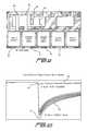
- FIG. 3is a top view of the layout of a tape gasket for an immunosensor cartridge.
- FIG. 4is an isometric top view of an immunosensor cartridge base.
- FIG. 5is a schematic view of the layout of an immunosensor cartridge.
- FIG. 6is a schematic view of the fluid and air paths within an immunosensor cartridge, including sites for amending fluids with dry reagents.
- FIG. 8is a side view of the construction of an electrochemical immunosensor with antibody-labeled particles not drawn to scale.
- FIG. 9is a top view of the mask design for the conductimetric and immunosensor electrodes for an immunosensor cartridge.
- FIG. 10illustrates the electrochemical responses of immunosensors constructed with an anti-HCG antibody when presented with 50 mIU/mL of HCG.
- FIG. 12illustrates the maximum current obtained when an immunosensor constructed with an anti-HCG antibody is presented with various amounts of HCG.
- FIG. 13is a schematic illustration of enzymatic regeneration of an electroactive species.
- FIG. 14illustrates segment forming means
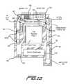
- FIG. 15is a top view of the preferred embodiment of an immunosensor cartridge.
- FIG. 19illustrates the cartridge device with a slidable sealing element for closing the blood entry port in the open position.
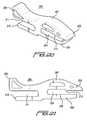
- FIG. 20illustrates a perspective view of the slidable sealing element.
- FIG. 21illustrates a side view of the slidable sealing element.
- FIG. 22illustrates the decreased background current at a troponin I immunosensor as a function of sodium chloride added to the sample. Addition of about 100 mM sodium ion brings the sample concentration to about 240 mM (assuming a typical blood sample sodium ion concentration of about 140 mM).
- FIG. 24is a schematic representation of a whole blood immunoassay with an immunoreference electrode.
- the present inventionpermits rapid in situ determinations of analytes using a cartridge having an array of analyte sensors and means for sequentially presenting a sample and a fluid (amended or not) to the analyte array.
- the cartridgesare designed to be preferably operated with a reading device, such as that disclosed in U.S. Pat. No. 5,096,669 to Lauks et al., issued Mar. 17, 1992, or U.S. Pat. No. 5,821,399 to Zelin, issued Oct. 13, 1998, which are both hereby incorporated by reference in their respective entireties.
- the inventionprovides cartridges and methods of their use for processing liquid samples to determine the presence or amount of an analyte in the sample.
- the cartridgescontain a metering means, which permits an unmetered volume of sample to be introduced, from which a metered amount is processed by the cartridge and its associated reading apparatus.
- the metering meanscomprises an elongated sample chamber bounded by a capillary stop and having along its length an air entry point. Air pressure exerted at the air entry point drives a metered volume of the sample past the capillary stop. The metered volume is predetermined by the volume of the sample chamber between the air entry point and the capillary stop.
- the cartridgemay have a closure means for sealing the sample port in an air-tight manner.
- This closure deviceis slidable with respect to the body of the cartridge and provides a shearing action that displaces any excess sample located in the region of the port; reliably sealing a portion of the sample in the holding chamber between the entry port and the capillary stop.
- the cartridgeis sealed by slidably moving a sealing element over the surface of the cartridge in a manner that displaces excess fluid sample away from the sample orifice, seals a volume of the fluid sample within the internal fluid sample holding chamber, and inhibits fluid sample from prematurely breaking through the internal capillary stop.
- the seal obtained by this slidable closure meansis irreversible and prevents excess blood from being trapped in the cartridge because the closure means moves in the plane of the orifice through which blood enters the cartridge and provides a shearing action that seals blood below the plane of the entry port; moving excess blood, i.e., blood above the plane of the orifice, away from the entry port and optionally to a waste chamber.
- FIGS. 18 , 19 , 20 and 21show a separate slidable element 200 in FIGS. 18 , 19 , 20 and 21 .
- FIG. 18shows a cartridge device comprising a modified version of the cover of FIG. 1 attached to the base of FIG. 4 with the intervening adhesive layer 21 shown in FIG. 3 along with the separate slidable closure element 200 . It is shown in the closed position where it seals the blood entry port in an air-tight manner.
- FIG. 19shows the same components as FIG. 18 , but with the slidable closure element in the open position, where the blood entry port 4 can receive blood.
- element 200is manually actuated from the open to the closed position after blood has been added to the entry port and it enters the holding chamber 34 . Any excess blood in the region of the entry port is moved into an overflow chamber 201 or an adjacent retaining region. This chamber or region may include a blood-absorbing pad or material to retain the excess blood.
- the sealing element 200also shown in FIGS. 20 and 21 , has a proximal end and a distal end; the proximal end has at least one anterior prong 202 and at least one posterior prong 203 , preferably the anterior prong has a greater thickness relative to the posterior prong when viewing a longitudinal cross section of the sealing element.
- the prongsare separated by a gap 204 , which permits the slidable movement of said sealing element relative the cartridge.
- the anterior prongslides over and across at least a portion of the device's substantially planar surface 205 in the region of the blood entry port; and the posterior prong slides under a portion of a face 206 of the cartridge opposite its substantially planar surface 205 .
- the sealing elementmay also include a dome-like shape 207 on the anterior prong while the posterior prong includes a substantially planar shape 208 when viewing the longitudinal cross section of said sealing element, as in FIG. 21 .
- the gap 204 separating the prongsruns approximately half the length of said sealing element 200 .
- the anterior prongremains substantially rigid as this prong slides over and across the device at 205 , while the posterior prong may flex as this prong slides under 205 .
- the anterior prongmay also be longer than the posterior prong so that a tip of the anterior prong extends beyond the tip of the posterior prong.
- the sealing elementcan also include, at the distal end, anterior prong 209 and posterior prong 210 separated by a gap 211 that runs approximately a third of the length of said sealing element.
- 209may includes a fin-like shape, while 210 may have a substantially planar shape when viewing a longitudinal cross section of the sealing element.
- Preferably 209has a tip that extends beyond 210 .
- the sealing elementis preferably made from a plastic material with mechanical properties and dimensions that permit the desired degree of flexing. Such materials include polyesters, ABS, acetal polymers and the like, that are suitable for injection molding.
- the sealing elementalso can include a locking feature 212 , which engages after the sealing element covers the blood entry port into a groove 213 in the base of the device. This ensures that the sealing element remains in the closed position throughout the assay procedure. Engagement of the sealing element in the closed position abuts it in an airtight manner to the region surrounding the blood entry port. Additionally, grooves and proud features may be molded into the sealing element and cartridge base to assure that when the sealing element is moved from the open to closed position, it tracks to the desired closed position completely covering the blood entry port. An additional locking feature may be included on prong 203 and the cartridge base.
- the blood entry port 4may be an orifice that is circular, as shown in FIG. 19 , or oval and the diameter of the orifice is generally in the range 0.2-5 mm, preferably 1-2 mm, or having a perimeter of 1-15 mm for an oval.
- the region around the orificemay be selected to be hydrophobic or hydrophilic to control the drop-shape of the applied blood sample to promote entry into the entry port.
- itmay be a portion of an adhesive tape material 21 that is capable of forming an airtight seal with the sealing means.
- this sealing elementprevents blood being pushed beyond the capillary stop element 25 at the end of the blood holding chamber 34 .
- the presence of a small amount of blood beyond the capillary stopis not significant for tests that measure bulk concentration of an analyte and thus do not depend on sample volume.
- the sealing elementimproves metering accuracy of the device and assures the assayed segment of sample is appropriately positioned with respect to the immunosensor, when the analyzer actuates the sample within the cartridge's conduits.
- sealing element 200is positioned within a few thousandths of an inch above the surface of the tape gasket 21 of FIG. 3 .
- the entry portis sealed by the subsequent lowering of the surface of 200 to the adhesive tape gasket when it engages locking features 212 and 213 . Once this seal is achieved it is essentially irreversible. Furthermore, since the tape is essentially incompressible and the orifice has a small diameter, any inadvertent pressure applied to the sealing element by the user will not cause the blood to move beyond the capillary stop.
- sealing element 200 and its attendant featuresare particularly advantageous for an immunoassay and DNA testing cartridges, they can also be used with cartridges that have sensors for other tests including sodium ion, glucose, activated clotting time and the like. It can be considered applicable to any cartridge with an immunosensor, electrochemical sensor, acoustic-wave sensor, optical sensor and the like.
- a reliable means for introducing more than one drop of blood into the blood holding chamber without entraining bubbleshas been developed.
- a coagulation assaye.g. prothrombin time (PT)
- the cartridgeneeds to work with a few drops of blood from a fingerstick.
- the blood-entry portcan be designed to receive multiple drops of blood without successive drops causing trapped bubbles to form in the holding chamber 34 by treating the holding chamber with a Corona and/or a reagent cocktail.
- Surface 34is first Corona treated to provide charged surface groups that will promote spreading of the aqueous printed cocktail.
- the process variablesinclude the amount of power required to treat the material, the material speed, the width, the number of sides to be treated, and the responsiveness of a particular material to corona treatment, which variables can be determined by a skilled operator.
- the typical place to install a corona treatmentis in-line with the printing, coating, or laminating process. Another common installation is directly on a blown film or cast film extruder since fresh material is more receptive to corona treatment.
- the reagent concentrationmust be low so that it works as desired, but does not interfere with the assay, e.g. components in blood that give rise to the coagulation cascade, as in PT, APTT and ACT assays.
- the assaye.g. components in blood that give rise to the coagulation cascade, as in PT, APTT and ACT assays.
- One skilled in the artwill not need unreasonable experimentation here, i.e. freshly made cartridges with processes 3 and 4 should have the same assay results.
- the actual concentrationswill depend on the design of the cartridge, dimensions, plastics etc.
- the signal-to-noise ratiois a well known factor in any measurement.
- electroactive speciese.g. p-aminophenol
- PVApolyvinyl alcohol
- a steady-state currentis measured in the immunosensor which is effectively independent of the transport rate and electrode kinetics, but is a function of the enzymatic rate of production of the detectable species, such as p-aminophenol generated from p-aminophenol phosphate by the enzyme alkaline phosphatase (attached to the second antibody).
- Wafer-level microfabrication of a preferred embodiment of the immunosensoris as follows.
- the base electrode ( 94 of FIG. 9 )consists of a square array of 7 um gold disks on 15 um centers.
- the arraycovers a circular region approximately 600 um in diameter, and is achieved by photo-patterning a thin layer of polyimide of thickness 0.35 um over a substrate made from a series of layers comprising Si/SiO2/TiW/Au.
- the array of 7 um microelectrodesaffords high collection efficiency of electroactive species with a reduced contribution from any electrochemical background current associated with the capacitance of the exposed metal.
- the inclusion of a PVA layer over the metalsignificantly enhances the reduction of background currents.
- the improved background screening properties of the PVA layerwere established by including alkaline phosphatase (ALP) into the patterned layer to assess collection efficiency and by comparing the background and p-aminophenol currents in solutions containing ALP.
- ALPalkaline phosphatase
- the PVA layerwas associated with a reduction in background current of about a factor of three, without any significant attenuation of the p-aminophenol signal.
- suppression of the background currentis likely to involve a degree of permselectivity towards p-aminophenol over electrochemical contaminants and other species that adsorb at the electrode surface which modify the double layer capacitance.
- the layermay have an effect on the electrode surface that preferentially reduces the rate of electrochemically irreversible (background) reactions, while affecting relatively reversible reactions, e.g. p-aminophenol, to a lesser degree.
- the absorbent nature of the PVA layermay aid in maintaining continuity (conductivity) during an amperometric analysis. Failure to maintain conductivity may result in a drifting potential that would contribute to background noise.
- the immuno-reference sensoris preferably the same in all significant respects (e.g, dimensions, porous screening layer, latex particle coating, and metal electrode composition) as the immunosensor except that the capture antibody for the analyte (for instance, cTnI) is replaced by an antibody to a plasma protein that naturally occurs in samples (both normal and pathological) at a high concentration.
- the immunosensor and reference immunosensormay be fabricated as adjacent structures 94 and 96 , respectively, on a silicon chip.
- troponin I assayWhile the preferred embodiment is described for a troponin I assay, this structure is also useful for other cardiac marker assays including troponin T, creatine kinase MB, procalcitonin, BNP, proBNP, myoglobin and the like, plus other sandwich assays used in clinical diagnostics.
- suitable antibodies that bind to plasma proteinsinclude antibodies to human serum albumin, fibrinogen and IgG fc region, with albumin being preferred.
- any native protein or blood component that occurs at a concentration of greater than about 100 ng/mLcan be used if an appropriate antibody is available.
- the main requirement of the proteinis being present in sufficient amounts to coat the sensor quickly compared to the time needed to perform the analyte assay.
- the proteinis present in a blood sample at a concentration sufficient to bind more than 50% of the available antibody on the reference immunosensor within about 100 seconds of contacting a blood sample.
- the second immobilized antibodyhas an affinity constant of about 1 ⁇ 10( ⁇ 7) to about 1 ⁇ 10( ⁇ 15)M.
- an antibody to albumin having an affinity constant of about 1 ⁇ 10( ⁇ 10) Mis preferred, due to the high molar concentration of albumin in blood samples, which is about 1 ⁇ 10( ⁇ 4) M.
- Carboxylate-modified latex microparticlessupplied by Bangs Laboratories Inc. or Seradyn Microparticles Inc. coated with anti-cTnI and anti-HSA are both prepared by the same method.
- the particlesare first buffer exchanged by centrifugation, followed by addition of the antibody, which is allowed to passively adsorb onto the particles.
- the carboxyl groups on the particlesare then activated with EDAC in MES buffer at pH 6.2, to form amide bonds to the antibodies. Any bead aggregates are removed by centrifugation and the finished beads are stored frozen.
- Coated beadswere prepared using covalent attachment from a mixture comprising 7 mg of anti-HSA and 100 mg of beads. Using this preparation a droplet of about 0.4 nL, comprising about 1% solids in deionized water, was microdispensed (using the method and apparatus of U.S. Pat. No. 5,554,339, incorporated here by reference) onto a photo-patterned porous polyvinyl alcohol permselective layer covering sensor 96 , and allowed to dry. The dried particles adhered to the porous layer and substantially prevented their dissolution in the blood sample or the washing fluid.
- HSAanti-human serum albumin
- immunosensor 94is coated with beads having both a plasma protein antibody, e.g. anti-HSA, and the analyte antibody, e.g. anti-cTnI.
- Latex beads made with the about 2 mg or less of anti-HSA per 100 mg of beads and then saturation-coated with anti-cTnIprovide superior non-specific binding properties at the immunosensor. It has been found that the slope (signal versus analyte concentration) of the troponin assay is not materially affected because there is sufficient anti-cTnI on the bead to capture the available analyte (antigen).
- An important aspect of immunosensors having a reference immunosensoris the “humanizing” of the surface created by a layer of plasma protein, preferably the HSA/anti-HSA combination. This appears to make the beads less prone to non-specific binding of the antibody-enzyme conjugate. It also seems to reduce bead variability. Without being bound by theory, it appears that as the sensors are covered by the sample they are rapidly coated with native albumin due to the anti-HSA surface. This gives superior results compared to conventional blocking materials which are dried down in manufacturing and re-hydrated; typically after a long period in storage. Another advantage to “humanizing” the sensor surface is that it provides an extra mode of resistance to human anti-mouse antibodies (HAMA) and other heterophile antibody interferences. The effects of HAMA on immunoassays are well known.
- HAMAhuman anti-mouse antibodies
- Another use of the immuno-reference sensor of the inventionis to monitor the wash efficiency obtained during the analytical cycle.
- one source of background noiseis the small amount of enzyme conjugate still in solution, or non-specifically absorbed on the sensor and not removed by the washing step.
- This aspect of the inventionrelates to performing an efficient washing step using a small volume of washing fluid, by introducing air segments as mentioned in Example 2.
- the currents associated with oxidation of p-aminophenol at immunosensor 94 and immuno-reference sensor 96 arising from the activity of ALP,are recorded by the analyzer.
- the potentials at the immunosensor and immuno-reference sensorare poised at the same value with respect to a silver-silver chloride reference electrode.
- the analyzersubtracts the signal of the immuno-reference sensor from that of the immunosensor according to equation (4). Where there is a characteristic constant offset between the two sensors, this also is subtracted.
- An additional use of this immuno-reference sensoris to detect anomalous sample conditions, such as improperly anti-coagulated samples which deposit material throughout the conduits and cause increased currents to be measured at both the immunosensor and the immuno-reference sensor. This effect is associated with both non-specifically adsorbed enzyme and enzyme remaining in the thin layer of wash fluid over the sensor during the measurement step.
- the level of signal at an immunosensordepends on the extent of washing. For example, longer washing with more fluid/air segment transitions can give a lower signal level due to a portion of the specifically bound conjugate being washed away. While this may be a relatively small effect, e.g. less than 5%, correction can improve the overall performance of the assay. Correction may be achieved based on the relative signals at the sensors, or in conjunction with a conductivity sensor located in the conduit adjacent to the sensors, acting as a sensor for detecting and counting the number of air segment/fluid transitions. This provides the input for an algorithmic correction means embedded in the analyzer.
- the reference immunosensor with an endogenous proteine.g. HSA
- an immuno-reference sensor coated with antibody to an exogenous proteine.g. bovine serum albumin (BSA).
- BSAbovine serum albumin
- the step of dissolving a portion of the BSA in the sample, provided as an additional reagent, prior to contacting the sensorsis needed.
- This dissolution stepcan be done with BSA as a dry reagent in the sample holding chamber of the cartridge, or in an external collection device, e.g. a BSA-coated syringe.
- This approachoffers certain advantages, for example the protein may be selected for surface charge, specific surface groups, degree of glycosylation and the like. These properties may not necessarily be present in the available selection of endogenous proteins.
- An electrochemical immunosensor of the type described herecan exhibit a bias between whole-blood versus plasma.
- immunoassays for markers such as troponin and the likeare measured and reported as plasma or serum values.
- a correction factor or a means for eliminating the biasneeds to be employed. It has been found that two aspects of this bias can be eliminated: (i) the bias in whole-blood electrochemical immunoassays associated with components of the buffy coat (which consists of white blood cells and platelets), and (ii) the bias associated with hematocrit variations between samples.
- the buffy coatis a layer of leukocytes and platelets that forms above the erythrocytes when blood is centrifuged. It has been observed that a white cell (or leukocyte) interference occurs on immunosensors having beads coated with an analyte antibody, e.g., troponin antibody. Control experiments showed that this positive bias is absent in plasma samples and in blood samples where the buffy coat has been removed. Without being bound by theory, it appears that leukocytes are able to stick to the immunosensor and promote non-specific binding of the enzyme-labeled antibodies, which remain bound even after a washing step. It has been found that this bias can be partially eliminated by adding a small amount of an antibody to human serum albumin during bead preparation.
- albumin from the samplerapidly coats the beads as described above. Once they are coated with a layer of native albumin the leukocytes do not recognize the beads as an opsonized surface, resulting in the observed effect of limiting the leukocytes' ability to cause the bias.
- FIG. 22is a graph of the difference in net current at the immunosensor versus added NaCl concentration.
- sufficient saltis added to the blood-holding chamber of the cartridge in a dried down form able to dissolve in the sample prior to the measurement step. Because the holding chamber has a volume of about 10 uL in the preferred cartridge design, this requires about 60 ug of NaCl.
- a mechanism that accounts for reduced interferencemay be that the salt causes osmotic shrinkage of the leukocytes, since this is an established phenomenon with erythrocytes. This interpretation is consistent with the leukocytes' impaired ability to interact with the immunosensor.
- saltis added to the sample by coating the wall of the sample holding chamber with a mixture of NaCl, lactitol and DEAE dextran at pH 7.4 using Tris at about 5% total solids.
- Gelatin, cellulose and PVAcan also be used as the support matrix, but the dissolution rate is not quite as fast as the lactitol and DEAE mixture.
- Sample hematocrit valuesmay vary widely between immunoassays performed on whole-blood and this can affect the results. A way to eliminate this effect has been discovered.
- the reagents that form the immuno-complexdissolve into the plasma fraction only, not into the cells, which are predominantly erythrocytes. Erythrocytes typically occupy about 40% of a blood sample, though this can vary widely between patients.
- the percentage of the blood sample volume occupied by these cellsis called the hematocrit value. For a given volume of blood, the higher the hematocrit value the less plasma volume is available for a given amount of reagent to dissolve in; thus, the effective reagent concentration is higher.
- hematocritis an inverse function of conductivity, assuming a normal concentration of current-carrying ions in the sample.
- standard curvesare created using samples with independently determined analyte concentrations and hematocrit values.
- an algorithmcan be developed and embedded into the analyzer and used for real samples, whereby the conductivity measured at an adjacent sensor in the cartridge is used to estimate hematocrit and correct the signal from the immunosensor. For example, the algorithm may simply subtract a percentage of the signal per hematocrit unit in order to correct the result to a hematocrit of zero, i.e. plasma.
- the embodiments described aboveprovide means for the individual elimination of the buffy coat interference and variable hematocrit values in electrochemical immunoassays performed on whole-blood samples. It is however desirable to deal with both interferences in the same sample and at the same sensor.
- the following methodassures that the addition of salt to the sample to eliminate the buffy coat interference does not affect the hematocrit measurement, which is based on a conductivity measurement.
- Those skilled in the artwill recognize that adding salt to a blood sample with an otherwise normal concentration of ions will increase its conductivity, thus giving an inaccurately low value of hematocrit.
- the present embodimentminimizes this problem.
- the PNCFincreases from 1.0 to about 1.3 and as the hematocrit further increases from about 30 to about 60, the PNCF decreases back to a value of about 1.0.
- the advantage of using this methodis that the algorithm for the correction no longer involves discrete estimation of the hematocrit of the sample.
- the salt additioncan be generalized to increased ionic strength or osmolarity in minimizing the buffy coat interference.
- a cartridge of the present inventionhas the advantage that the sample and a second fluid can contact the sensor array at different times during an assay sequence.
- the sample and second fluidmay also be independently amended with other reagents or compounds present initially as dry coatings within the respective conduits. Controlled motion of the liquids within the cartridge further permits more than one substance to be amended into each liquid whenever the sample or fluid is moved to a new region of the conduit. In this way, provision is made for multiple amendments to each fluid, greatly extending the complexity of automated assays that can be performed, and therefore enhancing the utility of the present invention.
- segments within the conduitsare also used to assist in cleaning and rinsing the conduits by passing the air-liquid interface of a segment over the sensor array or other region to be rinsed at least once. It has been found that more efficient rinsing, using less fluid, is achieved by this method compared to continuous rinsing by a larger volume of fluid.
- One embodiment of the inventiontherefore, provides a single-use cartridge with a sample-holding chamber connected to a first conduit which contains an analyte sensor or array of analyte sensors.
- a second conduitpartly containing a fluid, is connected to the first conduit and air segments can be introduced into the fluid in the second conduit in order to segment it.
- Pump meansare provided to displace the sample within the first conduit, and displaces fluid from the second conduit into the first conduit.
- the sensor or sensorscan be contacted first by a sample and then by a second fluid.
- a second embodiment of the cartridgeincludes a closeable valve located between the first conduit and a waste chamber.
- This embodimentpermits displacement of the fluid from the second conduit into the first conduit using only a single pump means connected to the first conduit.
- This embodimentfurther permits efficient washing of the conduits of the cartridge of the present invention, which is an important feature of a small single-use cartridge.
- the sampleis displaced to contact the sensors, and is then displaced through the closeable valve into the waste chamber.
- the closeable valveseals the opening to the waste chamber, providing an airtight seal that allows fluid in the second conduit to be drawn into contact with the sensors using only the pump means connected to the first conduit.
- the closeable valvepermits the fluid to be displaced in this manner and prevents air from entering the first conduit from the waste chamber.
- both a closeable valve and means for introducing segments into the conduitare provided.
- This embodimenthas many advantages, among which is the ability to reciprocate a segmented fluid over the sensor or array of sensors. Thus a first segment or set of segments is used to rinse a sensor, and then a fresh segment replaces it for taking measurements. Only one pump means (that connected to the first conduit) is required.
- analyte measurementsare performed in a thin-film of liquid coating an analyte sensor.
- Such thin-film determinationsare preferably performed amperometrically.
- This cartridgediffers from the foregoing embodiments in having both a closeable valve that is sealed when the sample is expelled through the valve, and an air vent within the conduits that permits at least one air segment to be subsequently introduced into the measuring fluid, thereby increasing the efficiency with which the sample is rinsed from the sensor, and further permitting removal of substantially all the liquid from the sensor prior to measurement, and still further permitting segments of fresh liquid to be brought across the sensor to permit sequential, repetitive measurements for improved accuracy and internal checks of reproducibility.
- the analysis scheme for the detection of low concentrations of immunoactive analyterelies on the formation of an enzyme labeled antibody/analyte/surface-bound antibody “sandwich” complex.
- concentration of analyte in a sampleis converted into a proportional surface concentration of an enzyme.
- the enzymeis capable of amplifying the analyte's chemical signal by converting a substrate to a detectable product. For example, where alkaline phosphatase is the enzyme, a single enzyme molecule can produce about nine thousand detectable molecules per minute, providing several orders of magnitude improvement in the detectability of the analyte compared to schemes in which an electroactive species is attached to the antibody in place of alkaline phosphatase.
- the immunosensoris advantageously microfabricated from a base sensor of an unreactive metal such as gold, platinum or iridium, and a porous permselective layer which is overlaid with a bioactive layer attached to a microparticle, for example latex particles.
- the microparticlesare dispensed onto the porous layer covering the electrode surface, forming an adhered, porous bioactive layer.
- the bioactive layerhas the property of binding specifically to the analyte of interest, or of manifesting a detectable change when the analyte is present, and is most preferably an immobilized antibody directed against the analyte.
- one goal of the present inventionis to provide an immunosensor cartridge that is preferably operated in a basic sense as follows.
- the inventionis not restricted to embodiments comprising an immunosensor, but includes any ligand-receptor interaction, including complimentary strands of DNA and RNA, biotin-avidin and the like.
- An unmetered amount of a preferably biological sampleis placed into the sample chamber of the cartridge, and the cartridge is placed into a reading apparatus.
- a metered portion of the sampleis amended with at least one antibody-enzyme conjugate, and is then contacted with the immunosensor.
- the assaycan be run in a system where the sample and other fluids and reagents are thermostated at a given temperature, e.g. 37° C.
- the assaymay be run at ambient temperature, without any correction, or with correction to a standardized temperature based on measurement of the ambient value.
- a battery-powered analyzeris used and it is generally desirable to conserve battery life, it may be desirable to heat only the capture location of the assay device or cartridge.
- the ambient temperaturewill have an effect on the cooling of the sample if it enters regions adjacent to the capture location.
- Equation 7the actual coefficients in Equation 7 will depend on the reagent components and have some sensitivity to the means by which the immunoassay is carried out, e.g. the capture time.
- the value of fCondis limited by equations 8 and 9.
- equation 8if the measured conductivity is below a value expected for a Hct value of for example 15 percent, then the sample is treated as a plasma sample and the correction factor is set to 5.
- the coverfurther comprises two paddles 6 , 7 , that are moveable relative to the body of the cover, and which are attached to it by flexible hinge regions 5 , 10 .
- paddle 6exerts a force upon an air bladder comprised of cavity 43 , which is covered by thin-film gasket 21 , to displace fluids within conduits of the cartridge.
- paddle 7exerts a force upon the gasket 21 , which can deform because of slits 22 cut therein.
- the cartridgeis adapted for insertion into a reading apparatus, and therefore has a plurality of mechanical and electrical connections for this purpose. It should also be apparent that manual operation of the cartridge is possible.
- the gaskettransmits pressure onto a fluid-containing foil pack filled with approximately 130 uL of analysis/wash solution (“fluid”) located in cavity 42 , rupturing the package upon spike 38 , and expelling fluid into conduit 39 , which is connected via a short transecting conduit in the base to the sensor conduit.
- the analysis fluidfills the front of the analysis conduit first pushing fluid onto a small opening in the tape gasket that acts as a capillary stop.
- Other motions of the analyzer mechanism applied to the cartridgeare used to inject one or more segments into the analysis fluid at controlled positions within the analysis conduit. These segments are used to help wash the sensor surface and the surrounding conduit with a minimum of fluid.
- the coverfurther comprises a hole covered by a thin pliable film 8 .
- pressure exerted upon the filmexpels one or more air segments into a conduit 20 through a small hole 28 in the gasket.
- the lower surface of the basefurther comprises second conduit 11 , and first conduit 15 .
- Second conduit 11includes a constriction 12 , which controls fluid flow by providing resistance to the flow of a fluid.
- Optional coatings 13 , 14provide hydrophobic surfaces, which together with gasket holes 31 , 32 , control fluid flow between conduits 11 , 15 .
- a recess 17 in the baseprovides a pathway for air in conduit 34 to pass to conduit 34 through hole 27 in the gasket.
- thin-film gasket 21comprises various holes and slits to facilitate transfer of fluid between conduits within the base and the cover, and to allow the gasket to deform under pressure where necessary.
- hole 24permits fluid to flow from conduit 11 into waste chamber 44 ;
- hole 25comprises a capillary stop between conduits 34 and 11 ;
- hole 26permits air to flow between recess 18 and conduit 40 ;
- hole 27provides for air movement between recess 17 and conduit 34 ;
- hole 28permits fluid to flow from conduit 19 to waste chamber 44 via optional closeable valve 41 .
- Holes 30 and 33permit the plurality of electrodes that are housed within cutaways 35 and 37 , respectively, to contact fluid within conduit 15 .
- cutaway 37houses a ground electrode, and/or a counter-reference electrode
- cutaway 35houses at least one analyte sensor and, optionally, a conductimetric sensor.
- conduit 34is the sample holding chamber that connects the sample entry port 4 to first conduit 11 in the assembled cartridge.
- Cutaway 35houses the analyte sensor or sensors, or an analyte responsive surface, together with an optional conductimetric sensor or sensors.
- Cutaway 37houses a ground electrode if needed as a return current path for an electrochemical sensor, and may also house an optional conductimetric sensor.
- Cutaway 36provides a fluid path between gasket holes 31 and 32 so that fluid can pass between the first and second conduits.
- Recess 42houses a fluid-containing package, e.g., a rupturable pouch, in the assembled cartridge that is pierced by spike 38 because of pressure exerted upon paddle 7 upon insertion into a reading apparatus.
- An air bladderis comprised of recess 43 which is sealed on its upper surface by gasket 21 .
- the air bladderis one embodiment of a pump means, and is actuated by pressure applied to paddle 6 which displaces air in conduit 40 and thereby displaces the sample from sample chamber 34 into first conduit 15 .
- This arrangementis therefore one possible embodiment of a metering means for delivering a metered amount of an unmetered sample into the conduits of the cartridge.
- a means for metering a sample segmentis provide in the base plastic part.
- the segment sizeis controlled by the size of the compartment in the base and the position of the capillary stop and air pipe holes in the tape gasket. This volume can be readily varied from 2 to 200 microliters. Expansion of this range of sample sizes is possible within the context of the present invention.
- the fluidis pushed through a pre-analytical conduit 11 that can be used to amend a reagent (e. g. particles or soluble molecules) into the sample prior to its presentation at the sensor conduit 19 .
- a reagente. g. particles or soluble molecules
- the amending reagentmay be located in portion 15 , beyond portion 16 . Pushing the sample through the pre-analytical conduit also serves to introduce tension into the diaphragm pump paddle 7 which improves its responsiveness for actuation of fluid displacement.
- a waste chamberis provided, 44 , for sample and/or fluid that is expelled from the conduit, to prevent contamination of the outside surfaces of the cartridge.
- a vent connecting the waste chamber to the external atmosphereis also provided, 45 .
- FIG. 5a schematic diagram of the features of a cartridge and components is provided, wherein 51 - 57 are portions of the conduits and sample chamber that can optionally be coated with dry reagents to amend a sample or fluid.
- the sample or fluidis passed at least once over the dry reagent to dissolve it.
- Reagents used to amend samples or fluid within the cartridgeinclude antibody-enzyme conjugates, or blocking agents that prevent either specific or non-specific binding reactions among assay compounds.
- a surface coatingthat is not soluble but helps prevent non-specific adsorption of assay components to the inner surfaces of the cartridges can also be provided.
- an amending substancecan be preferentially dissolved and concentrated within a predetermined region of the segment. This is achieved through control of the position and movement of the segment. Thus, for example, if only a portion of a segment, such as the leading edge, is reciprocated over the amended substance, then a high local concentration of the substance can be achieved close to the leading edge. Alternatively, if an homogenous distribution of the substance is desired, for example if a known concentration of an amending substance is required for a quantitative analysis, then further reciprocation of the sample or fluid will result in mixing and an even distribution.
- a closeable valveis provided between the first conduit and the waste chamber.
- this valve, 58is comprised of a dried sponge material that is coated with an impermeable substance. In operation, contacting the sponge material with the sample or a fluid results in swelling of the sponge to fill the cavity 41 , thereby substantially blocking further flow of liquid into the waste chamber 44 .
- the wetted valvealso blocks the flow of air between the first conduit and the waste chamber, which permits the first pump means connected to the sample chamber to displace fluid within the second conduit, and to displace fluid from the second conduit into the first conduit in the following manner.
- the sampleis moved into the post-analytical conduit 19 where it can be amended with another reagent. It can then be moved back to the sensor and a second reaction period can begin.
- the post-analysis conduitcan serve simply to separate the sample segment from the sensor.
- a single closeable valvewhich connects the air vent of the sensor conduit to the diaphragm air pump. When this valve closes, the sample is locked in the post analytical conduit and cannot be moved back to the sensor chip.
- closeable valveexamples include, but are not limited to; a flexible flap held in an open position by a soluble glue or a gelling polymer that dissolves or swells upon contact with a fluid or sample thus causing the flap to close; and alternatively, in one specific embodiment, a thin layer of a porous paper or similar material interposed between a conduit and either the waste chamber or ambient air such that the paper is permeable to air while dry but impermeable when wet. In the latter case it is not necessary that the closeable valve be interposed between a conduit and the waste chamber: the valve passes little to no liquid before closing and so the valve is appropriately placed when positioned between a conduit and the ambient air surrounding the cartridge.
- a piece of filter paperis placed on an opening in the tape gasket in the fluid path to be controlled. Air can readily move through this media to allow fluid to be moved through the fluid path. When the fluid is pushed over this filter, the filter media becomes filled with liquid and further motion through the fluid path is stopped. Once the filter become wet, significant pressures would be required to move liquid through the pores of the filter. Air flow through the filter is also prevented because of the higher pressure required to push the liquid out of the filter, typically termed bubble pressure.
- This valve embodimentrequires very little liquid to actuate the valve, and actuation occurs rapidly and reliably. Materials, their dimensions, porosity, wettability, swelling characteristics and related parameters are selected to provide for rapid closure, within one second or more slowly, e.g. up to 60 seconds, after first contacting the sample, depending on the specific desired closure time.
- the closeable valveis a mechanical valve.
- a latex diaphragmis placed in the bottom of the air bladder on top of a specially constructed well.
- the wellcontains two openings which fluidically connect the air vent to the sample conduit.
- the analyzer plungerpushes to the bottom of the air bladder, it presses on this latex diaphragm which is adhesive backed and seals the connection between the two holes. This blocks the sample's air vent, locking the sample in place.
- FIG. 6which illustrates the schematic layout of an immunosensor cartridge
- pump means61 - 63 . While these pumps have been described in terms of specific embodiments, it will be readily understood that any pump means capable of performing the respective functions of pump means 61 - 63 may be used within the present invention.
- pump means 1 , 61must be capable of displacing the sample from the sample holding chamber into the first conduit; pump means 2 , 62 , must be capable of displacing fluid within the second conduit; and pump means 3 , 63 , must be capable of inserting at least one segment into the second conduit.
- pump means 3 , 63includes all methods by which one or more segments are inserted into the second conduit, such as a pneumatic means for displacing air from an air sac, a dry chemical that produces a gas when dissolved, or a plurality of electrolysis electrodes operably connected to a current source.
- the segmentis produced using a mechanical segment generating diaphragm that may have more than one air bladder or chamber.
- the well 8has a single opening which connects the inner diaphragm pump and the fluid filled conduit into which a segment is to be injected 20 .
- the diaphragmcan be segmented to produce multiple segments, each injected in a specific location within a fluid filled conduit.
- a segmentis injected using a passive feature.
- a well in the base of the cartridgeis sealed by tape gasket.
- the tape gasket covering the wellhas two small holes on either end. One hole is open while the other is covered with a filter material which wets upon contact with a fluid.
- the wellis filled with a loose hydrophilic material such as a cellulose fiber filter, paper filter or glass fiber filter. This hydrophilic material draws the liquid into the well in the base via capillary action, displacing the air which was formerly in the well. The air is expelled through the opening in the tape gasket creating a segment whose volume is determined by the volume of the well and the void volume of the loose hydrophilic material.
- the filter used to cover one of the inlets to the well in the basecan be chosen to meter the rate at which the fluid fills the well and thereby control the rate at which the segment is injected into the conduit in the cover.
- This passive featurepermits any number of controlled segments to be injected at specific locations within a fluid path and requires a minimum of space.
- FIG. 7illustrates the principle of an amperometric immunoassay according to specific embodiments of the present invention for determination of troponin I (TnI), a marker of cardiac function.
- a blood samplefor example, is introduced into the sample holding chamber of a cartridge of the present invention, and is amended by a conjugate molecule comprising alkaline phosphatase enzyme (AP) covalently attached to a polyclonal anti-troponin I antibody (aTnI) 71 .
- APalkaline phosphatase enzyme
- aTnIpolyclonal anti-troponin I antibody
- this complexbinds to the capture aTnI antibody 72 attached on, or close to, the immunosensor.
- the sensor chiphas a conductivity sensor which is used to monitor when the sample reaches the sensor chip.
- the time of arrival of the fluidcan be used to detect leaks within the cartridge: a delay in arrival signals a leak.
- the position of the sample segment within the sensor conduitcan be actively controlled using the edge of the fluid as a marker. As the sample/air interface crosses the conductivity sensor, a precise signal is generated which can be used as a fluid marker from which controlled fluid excursions can be executed.
- the fluid segmentis preferentially oscillated edge-to-edge over the sensor in order to present the entire sample to the sensor surface.
- a second reagentcan be introduced in the sensor conduit beyond the sensor chip, which becomes homogenously distributed during the fluid oscillations.
- the sensor chipcontains a capture region or regions coated with antibodies for the analyte of interest. These capture regions are defined by a hydrophobic ring of polyimide or another photolithographically produced layer. A microdroplet or several microdroplets (approximately 5-40 nanoliters in size) containing antibodies in some form, for example bound to latex microspheres, is dispensed on the surface of the sensor. The photodefined ring contains this aqueous droplet allowing the antibody coated region to be localized to a precision of a few microns.
- the capture regioncan be made from 0.03 to roughly 2 square millimeters in size. The upper end of this size is limited by the size of the conduit and sensor in present embodiments, and is not a limitation of the invention.
- the gold electrode 74is coated with a biolayer 73 comprising a covalently attached anti-troponin I antibody, to which the TnI/AP-aTnI complex binds.
- APis thereby immobilized close to the electrode in proportion to the amount of TnI initially present in the sample.
- the enzyme-antibody conjugatemay bind non-specifically to the sensor. Non-specific binding provides a background signal from the sensor that is undesirable and preferably is minimized.
- the rinsing protocols, and in particular the use of segmented fluid to rinse the sensorprovide efficient means to minimize this background signal.
- the senorcomprises two amperometric electrodes which are used to detect the enzymatically produced 4-aminophenol from the reaction of 4-aminophenylphosphate with the enzyme label alkaline phosphatase.
- the electrodesare preferably produced from gold surfaces coated with a photodefined layer of polyimide. Regularly spaced opening in the insulating polyimide layer define a grid of small gold electrodes at which the 4-aminophenol is oxidized in a 2 electron per molecule reaction.
- Sensor electrodesfurther comprise a biolayer, while reference electrodes can be constructed, for example, from gold electrodes lacking a biolayer, or from silver electrodes, or other suitable material. Different biolayers can provide each electrode with the ability to sense a different analyte.
- H 2 N—C 6 H 4 —OH ⁇ HN ⁇ C 6 H 4O+2H + +2e ⁇
- Substratessuch as p-aminophenol species, can be chosen such that the E 1/2 of the substrate and product differ substantially.
- the voltammetric half-wave potential (E 1/2 ) of the substrateis substantially higher (more positive) than that of the product.
- the productcan be selectively electrochemically measured in the presence of the substrate.
- the size and spacing of the electrodeplay an important role in determining the sensitivity and background signal.
- the important parameters in the gridare the percentage of exposed metal and the spacing between the active electrodes.
- the position of the electrodecan be directly underneath the antibody capture region or offset from the capture region by a controlled distance.
- the actual amperometric signal of the electrodesdepends on the positioning of the sensors relative to the antibody capture site and the motion of the fluid during the analysis. A current at the electrode is recorded that depends upon the amount of electroactive product in the vicinity of the sensor.
- the detection of alkaline phosphatase activity in this examplerelies on a measurement of the 4-aminophenol oxidation current. This is achieved at a potential of about +60 mV versus the Ag/AgCl ground chip.
- the exact form of detection useddepends on the sensor configuration.
- the array of gold microelectrodesis located directly beneath the antibody capture region.
- enzyme located on the capture siteconverts the 4-aminophenylphosphate to 4-aminophenol in an enzyme limited reaction.
- the concentration of the 4-aminophenylphosphateis selected to be in excess, e.g., 10 times the Km value.
- the analysis solutionis 0.1 M in diethanolamine, 1.0 M NaCl, buffered to a pH of 9.8. Additionally, the analysis solution contains 0.5 mM MgCl which is a cofactor for the enzyme. Alternatively, a carbonate buffer has the desired properties.
- the electrodeis located a few hundred microns away from the capture region.
- the enzyme productbuilds with no loss due to electrode reactions.
- the solutionis slowly pulled from the capture region over the detector electrode resulting in a current spike from which the enzyme activity can be determined.
- a planar non-conducting substrateis provided, 80 , onto which is deposited a conducting layer 81 by conventional means or microfabrication known to those of skill in the art.
- the conducting materialis preferably a noble metal such as gold or platinum, although other unreactive metals such as iridium may also be used, as may non-metallic electrodes of graphite, conductive polymer, or other materials.
- An electrical connection 82is also provided.
- a biolayer 83is deposited onto at least a portion of the electrode.
- a biolayermeans a porous layer comprising on its surface a sufficient amount of a molecule 84 that can either bind to an analyte of interest, or respond to the presence of such analyte by producing a change that is capable of measurement.
- a permselective screening layermay be interposed between the electrode and the biolayer to screen electrochemical interferents as described in U.S. Pat. No. 5,200,051.
- a biolayeris constructed from latex beads of specific diameter in the range of about 0.001 to 50 microns.
- the beadsare modified by covalent attachment of any suitable molecule consistent with the above definition of a biolayer.
- Many methods of attachmentexist in the art, including providing amine reactive N-hydroxysuccinimide ester groups for the facile coupling of lysine or N-terminal amine groups of proteins.
- the biomoleculeis chosen from among ionophores, cofactors, polypeptides, proteins, glycopeptides, enzymes, immunoglobulins, antibodies, antigens, lectins, neurochemical receptors, oligonucleotides, polynucleotides, DNA, RNA, or suitable mixtures.
- the biomoleculeis an antibody selected to bind one or more of human chorionic gonadotrophin, troponin I, troponin T, troponin C, a troponin complex, creatine kinase, creatine kinase subunit M, creatine kinase subunit B, myoglobin, myosin light chain, or modified fragments of these.
- modified fragmentsare generated by oxidation, reduction, deletion, addition or modification of at least one amino acid, including chemical modification with a natural moiety or with a synthetic moiety.
- the biomoleculebinds to the analyte specifically and has an affinity constant for binding analyte ligand of about 10 7 to 10 15 M ⁇ 1 .
- the biolayercomprising beads having surfaces that are covalently modified by a suitable molecule
- the biolayeris affixed to the sensor by the following method.
- a microdispensing needleis used to deposit onto the sensor surface a small droplet, preferably about 20 nL, of a suspension of modified beads. The droplet is permitted to dry, which results in a coating of the beads on the surface that resists displacement during use.
- the present inventionalso envisages embodiments in which the biolayer is coated upon particles that are mobile.
- the cartridgecan contain mobile microparticles capable of interacting with an analyte, for example magnetic particles that are localized to an amperometric electrode subsequent to a capture step, whereby magnetic forces are used to concentrate the particles at the electrode for measurement.
- mobile microparticles in the present inventionare that their motion in the sample or fluid accelerates binding reactions, making the capture step of the assay faster.
- a porous filteris used to trap the beads at the electrode.
- FIG. 9there is illustrated a mask design for several electrodes upon a single substrate.
- independent electrodes and leadscan be deposited.
- a plurality of immunosensors, 94 and 96 , and conductimetric sensors, 90 and 92are provided in a compact area at low cost, together with their respective connecting pads, 91 , 93 , 95 , and 97 , for effecting electrical connection to the reading apparatus.
- a very large array of sensorscan be assembled in this way, each sensitive to a different analyte or acting as a control sensor or reference immunosensor.
- immunosensorsare prepared as follows. Silicon wafers are thermally oxidized to form approximately a 1 micron insulating oxide layer. A titanium/tungsten layer is sputtered onto the oxide layer to a preferable thickness of between 100-1000 Angstroms, followed by a layer of gold that is most preferably 800 Angstroms thick. Next, a photoresist is spun onto the wafer and is dried and baked appropriately. The surface is then exposed using a contact mask, such as a mask corresponding to that illustrated in FIG. 9 . The latent image is developed, and the wafer is exposed to a gold-etchant.
- the patterned gold layeris coated with a photodefinable polyimide, suitably baked, exposed using a contact mask, developed, cleaned in an O 2 plasma, and preferably imidized at 350° C. for 5 hours.
- An optional metallization of the back side of the wafermay be performed to act as a resistive heating element, where the immunosensor is to be used in a thermostatted format.
- the surfaceis then printed with antibody-coated particles. Droplets, preferably of about 20 nL volume and containing 1% solid content in deionized water, are deposited onto the sensor region and are dried in place by air drying.
- an antibody stabilization reagentsupplied by SurModica Corp. or AET Ltd
- FIG. 10there are illustrated results obtained for analysis of samples containing 0 or 50 miU/mL human chorionic gonadotrophin (HCG) and an HCG-sensitive amperometric immunosensor.
- HCGhuman chorionic gonadotrophin
- a solution containing a p-aminophenol phosphateis supplied to a sensor which is previously treated with HCG and an anti-HCG polyclonal antibody conjugated to alkaline phosphatase.
- a currentincreases to a maximum 101 , and thereafter declines 102 , as substrate within the diffusion volume of the sensor is depleted and oxidized p-aminophenol accumulates.
- the signal at the electrodeis augmented by enzymatic regeneration of the electroactive species in the vicinity of the electrode.
- a phosphorylated ferroceneis used as the substrate for alkaline phosphatase attached to the antibody. Hydrolysis yields a ferrocene product, which is oxidized and detected at the electrode.
- glucose oxidase enzyme and glucoseare used to re-reduce the electrochemically oxidized ferrocene, with a consequent increase in the current and detection sensitivity.
- an electrode 130oxidizes or reduces the electroactive product 132 of alkaline phosphatase immobilized as a complex 131 on or close to the electrode surface.
- the electroactive species 132is regenerated from the product 133 by the catalytic action of enzyme 134 . This cycling reaction increases the concentration of electroactive species 132 in proximity to the electrode surface 130 , and thereby increases the current recorded at the electrode.
- FIG. 11there is shown dose-response results obtained using HCG and an HCG-responsive amperometric immunosensor. Amounts of HCG equivalent to 0 to 50 miU/mL are allowed to bind to the immobilized antibody attached to the electrode, as in FIG. 10 . Referring now to FIG. 12 , good linearity, and 121 , of the response of the peak sensor current with increasing HCG is found. Thus, it is demonstrated that this embodiment can precisely and rapidly quantify HCG in a sample.
- An unmetered fluid sampleis introduced into sample chamber 34 of a cartridge according to claim 1 , through sample entry port 4 .
- Capillary stop 25prevents passage of the sample into conduit 11 at this stage, and conduit 34 is filled with the sample. Lid 2 or element 200 is closed to prevent leakage of the sample from the cartridge.
- the cartridgeis then inserted into a reading apparatus, such as that disclosed in U.S. Pat. No. 5,821,399 to Zelin, which is hereby incorporated by reference. Insertion of the cartridge into a reading apparatus activates the mechanism which punctures a fluid-containing package located at 42 when the package is pressed against spike 38 . Fluid is thereby expelled into the second conduit, arriving in sequence at 39 , 20 , 12 and 11 .
- a pump meansapplies pressure to air-bladder 43 , forcing air through conduit 40 , through cutaways 17 and 18 , and into conduit 34 at a predetermined location 27 .
- Capillary stop 25 and location 27delimit a metered portion of the original sample. While the sample is within sample chamber 34 , it is optionally amended with a compound or compounds present initially as a dry coating on the inner surface of the chamber. The metered portion of the sample is then expelled through the capillary stop by air pressure produced within air bladder 43 . The sample passes into conduit 15 and into contact with the analyte sensor or sensors located within cutaway 35 .
- the sampleis amended prior to arriving at the sensor by, for example, an enzyme-antibody conjugate.
- An antibody that binds the analyte of interestis covalently attached to an enzyme that can generate a redox active substance close to an amperometric electrode.
- the enzymemay be alkaline phosphatase, which hydrolyzes certain organophosphate compounds, such as derivatives of p-aminophenol that liberate redox-active compounds when hydrolyzed.
- any enzyme capable of producing, destroying, or altering any compound that may be detected by a sensormay be employed in conjunction with a matching sensor.
- antibody-urease conjugatemay be used together with an ammonium sensor.
- the enzyme-antibody conjugate or conjugatesamends the sample and binds to the analyte of interest.
- the immunosensorcan comprise immobilized antibody that binds to an analyte of interest.
- the analyte of interestbinds to the sensor, together with antibody-enzyme conjugate to which it is attached.
- the sample containing the analyteis optionally passed repeatedly over the sensor in an oscillatory motion.
- an oscillation frequencyof between about 0.2 and 2 Hz is used, most preferably 0.7 Hz.
- enzymeis brought into close proximity to the amperometric electrode surface in proportion to the amount of analyte present in the sample.
- the sampleis ejected by further pressure applied to air bladder 43 , and the sample passes to waste chamber 44 .
- a wash stepnext removes non-specifically bound enzyme-conjugate from the sensor chamber.
- Fluid in the second conductis moved by a pump means 43 , into contact with the sensors.
- the analysis fluidis pulled slowly until the first air segment is detected at a conductivity sensor.
- the air segment or segmentcan be produced within a conduit by any suitable means, including but not limited to, passive means, as shown in FIG. 14 and described below; active means including a transient lowering of the pressure within a conduit using pump means whereby air is drawn into the conduit through a flap or valve; or by dissolving a compound pre-positioned within a conduit that liberates a gas upon contacting fluid in the conduit, where such compound may include a carbonate, bicarbonate or the like.
- This segmentis extremely effective at clearing the sample-contaminated fluid from conduit 15 .
- the efficiency of the rinsing of the sensor regionis greatly enhanced by the introduction of one or more air segments into the second conduit as described.
- a second advantage of introducing air segments into the fluidis to segment the fluid. For example, after a first segment of the fluid is used to rinse a sensor, a second segment is then placed over the sensor with minimal mixing of the two segments. This feature further reduces background signal from the sensor by more efficiently removing unbound antibody-enzyme conjugate. After the front edge washing, the analysis fluid is pulled slowly until the first air segment is detected at a conductivity sensor. This segment is extremely effective at clearing the sample-contaminated fluid which was mixed in with the first analysis fluid sample.
- a second advantage of introducing air segments into conduit twois to segment the fluid. For example, after a first segment of the fluid is used to rinse a sensor, a second segment is then placed over the sensor with minimal mixing of the two segments. This feature further reduces background signal from the sensor by more efficiently removing unbound antibody-enzyme conjugate.
- a new portion of fluidis placed over the sensors, and the current or potential, as appropriate to the mode of operation, is recorded as a function of time.
- a cartridge with a closeable valvepreferably located between the sensor chamber and the waste chamber, is herein illustrated by a specific embodiment in which the concentration of HCG is determined within a blood sample, which is introduced into the sample chamber of said cartridge.
- the diagnostic testsdetermine whether fluid or sample is present in the conduits using the conductivity electrodes; determine whether electrical short circuits are present in the electrodes; and ensure that the sensor and ground electrodes are thermally equilibrated to, preferably, 37° C. prior to the analyte determination.
- a metered portion of the samplepreferably between 4 and 200 ⁇ l, more preferably between 4 and 20 ⁇ l, and most preferably 7 ⁇ l, is used to contact the sensor as described in EXAMPLE 2.
- the edges defining the forward and trailing edges of the sampleare reciprocally moved over the sensor region at a frequency that is preferably between 0.2 to 2.0 Hz, and is most preferably 0.7 Hz.
- the enzyme-antibody conjugatedissolves within the sample, as previously described.
- the amount of enzyme-antibody conjugate that is coated onto the conduitis selected to yield a concentration when dissolved that is preferably higher than the highest anticipated HCG concentration, and is most preferably six times higher than the highest anticipated HCG concentration in the sample.
- the sampleis moved into the waste chamber via closeable valve 41 , wetting the closeable valve and causing it to close as previously described.
- the seal created by the closing of the valvepermits the first pump means to be used to control motion of fluid from conduit 11 to conduit 15 .
- the analyzer plungerretracts from the flexible diaphragm of the pump mean creating a partial vacuum in the sensor conduit. This forces the analysis fluid through the small hole in the tape gasket 31 and into a short transecting conduit in the base, 13 , 14 .
- the analysis fluidis pulled further and the front edge of the analysis fluid is oscillated across the surface of the sensor chip in order to shear the sample near the walls of the conduit.
- a conductivity sensor on the sensor chipis used to control this process.
- the efficiency of the processis monitored using the amperometric sensors through the removal of unbound enzyme-antibody conjugate which enhances the oxidation current measured at the electrode when the enzyme substrate, 4-aminophenyl phosphate is also present.
- the amperometric electrodesare polarized to 0.06 V versus the silver chloride reference-ground electrode.
- the fluidis composed of a 0.1 M carbonate or diethanolamine buffer, at pH 9.8, with 1 mM MgCl 2 , 1.0 M NaCl, 10 mM 4-aminophenylphosphate, and 10 ⁇ M NaI.
- the efficiency of the washis optimally further enhanced by introduction into the fluid of one or more segments that segment the fluid within the conduit as previously described.
- the air segmentmay be introduced by either active or passive means. Referring now to FIG. 14 , there is illustrated the construction of a specific means for passively introducing an air segment into said fluid.
- recess 140comprising a tapered portion 141 and a cylindrical portion that are connected.
- the tapered portionis in fluid connection with a hole 142 of similar diameter in the tape gasket ( FIG. 3 ) that separates the base ( FIG. 4 ) and cover ( FIGS. 1 and 2) of the assembled immunosensor cartridge.
- the recesscontains an absorbent material that, upon contact with fluid, withdraws a small quantity of fluid from a conduit thereby passively introducing an air segment into the conduit.
- the volume of the recess and the amount and type of material within itmay be adjusted to control the size of the air segment introduced.
- Specific materialsinclude, but are not limited to, glass filter, a laminate comprising a 3 micron Versapor filter bonded by sucrose to a 60% viscose chiffon layer.
- Fluidis forcibly moved towards sensor chip by the partial vacuum generated by reducing the mechanical pressure exerted upon paddle 6 , causing the “T” region of the sensor channel in the vicinity of the transecting conduit to fill with analysis fluid.
- the T region of the sensor channeloptionally has a higher channel height resulting a meniscus with a smaller radius of curvature.
- the conduit heightis optionally smaller.
- the analysis fluidpassively flows from the T region towards this low conduit height region washing the conduit walls. This passive leak allows further effective washing of the T region using a minimal volume of fluid.
- the fluid located within the second conduitcontains a substrate for the enzyme.
- amendment of the fluid using dried substrate within the second conduitmay be used.
- At least one sensor reading of a sampleis made by rapidly placing over the sensor a fresh portion of fluid containing a substrate for the enzyme. Rapid displacement both rinses away product previously formed, and provides now substrate to the electrode. Repetitive signals are averaged to produce a measurement of higher precision, and also to obtain a better statistical average of the baseline, represented by the current immediately following replacement of the solution over the sensor.
- Cartridge 150comprises a base and a top portion, preferably constructed of a plastic. The two portions are connected by a thin, adhesive gasket or thin pliable film.
- the assembled cartridgecomprises a sample chamber 151 into which a sample containing an analyte of interest is introduced via a sample inlet 152 .
- a metered portion of the sampleis delivered to the sensor chip 153 , via the sample conduit 154 (first conduit) as before by the combined action of a capillary stop 152 , preferably formed by a 0.012′′ laser cut hole in the gasket or film that connects the two portions of the cartridge, and an entry point 155 located at a predetermined point within the sample chamber whereby air introduced by the action of a pump means, such as a paddle pushing upon a sample diaphragm 156 .
- vent 157contains a wicking material that absorbs the sample and thereby seals the vent closed to the further passage of liquid or air.
- the wicking materialis preferably a cotton fiber material, a cellulose material, or other hydrophilic material having pores. It is important in the present application that the material is sufficiently absorbent (i.e., possesses sufficient wicking speed) that the valve closes within a time period that is commensurate with the subsequent withdrawal of the sample diaphragm actuating means described below, so that sample is not subsequently drawn back into the region of the sensor chip.
- a wash conduit (second conduit) 158connected at one end to a vent 159 and at the other end to the sample conduit at a point 160 of the sample conduit that is located between vent 157 and sensor chip 153 .
- a fluidis introduced into conduit 158 .
- the fluidis present initially within a foil pouch 161 that is punctured by a pin when an actuating means applies pressure upon the pouch.
- a short conduit 162that connects the fluid to conduit 154 via a small opening in the gasket 163 .
- a second capillary stopinitially prevents the fluid from reaching capillary stop 160 , so that the fluid is retained within conduit 158 .
- Air vent 164preferably comprising a small flap cut in the gasket or a membrane that vibrates to provide an intermittent air stream, provides a means for air to enter conduit 158 via a second vent 165 .
- the second vent 165preferably also contains wicking material capable of closing the vent if wetted, which permits subsequent depression of sample diaphragm 156 to close vent 165 , if required.
- fluidis drawn from conduit 158 , through capillary stop 160 , into conduit 154 . Because the flow of fluid is interrupted by air entering vent 164 , at least one air segment (a segment or stream of segments) is introduced.
- sample diaphragm 156draws the liquid containing at least one air segment back across the sensing surface of sensor chip 153 .
- the presence of air-liquid boundaries within the liquidenhances the rinsing of the sensor chip surface to remove remaining sample.
- the movement of the sample diaphragm 156is controlled in conjunction with signals received from the conductivity electrodes housed within the sensor chip adjacent to the analyte sensors. In this way, the presence of liquid over the sensor is detected, and multiple readings can be performed by movement of the fluid in discrete steps.
- a suitable filmis obtained by withdrawing fluid by operation of the sample diaphragm 156 , until the conductimetric sensor located next to the sensor indicates that bulk fluid is no longer present in that region of conduit 154 . It has been found that measurement can be performed at very low (nA) currents, the potential drop that results from increased resistance of a thin film between ground chip and sensor chip (compared to bulk fluid), is not significant.
- the ground chip 165is preferably silver/silver chloride. It is advantageous, to avoid air segments, which easily form upon the relatively hydrophobic silver chloride surface, to pattern the ground chip as small regions of silver/silver chloride interspersed with more hydrophilic regions, such as a surface of silicon dioxide.
- a preferred ground electrode configurationcomprises an array of silver/silver chloride squares densely arranged and interspersed with silicon dioxide. There is a further advantage in the avoidance of unintentional segments if the regions of silver/silver chloride are somewhat recessed.
- Regions R 1 -R 7represent specific regions of the conduits associated with specific operational functions.
- R 1represents the sample chamber
- R 2the sample conduit whereby a metered portion of the sample is transferred to the capture region, and in which the sample is optionally amended with a substance coated upon the walls of the conduit
- R 3represents the capture region, which houses the conductimetric and analyte sensors
- R 4 and R 5represent portions of the first conduit that are optionally used for further amendment of fluids with substances coated onto the conduit wall, whereby more complex assay schemes are achieved
- R 6represents the portion of the second conduit into which fluid is introduced upon insertion of the cartridge into a reading apparatus
- R 7comprises a portion of the conduit located between capillary stops 160 and 166 , in which further amendment can occur
- R 8represents the portion of conduit 154 located between point 160 and vent 157 , and which can further be used to amend liquids contained within.
- a userplaces a sample into the cartridge, places the cartridge into the analyzer and in 1 to 20 minutes, a quantitative measurement of one or more analytes is performed.
- a sequence of events that occur during the analysisis a non-limiting example of a sequence of events that occur during the analysis:
- a 25 to 50 ⁇ L sampleis introduced in the sample inlet 167 and fills to a capillary stop 151 formed by a 0.012′′ laser cut hole in the adhesive tape holding the cover and base components together.
- the userrotates a latex rubber disk mounted on a snap flap to close the sample inlet 167 and places the cartridge into the analyzer.
- the analyzermakes contact with the cartridge, and a motor driven plunger presses onto the foil pouch 161 forcing the wash/analysis fluid out into a central conduit 158 .
- a separate motor driven plungercontacts the sample diaphragm 156 pushing a measured segment of the sample along the sample conduit (from reagent region R 1 to R 2 ).
- the sampleis detected at the sensor chip 153 via the conductivity sensors.
- the sensor chipis located in capture region R 3 .
- the sampleis oscillated by means of the sample diaphragm 156 between R 2 and R 5 in a predetermined and controlled fashion for a controlled time to promote binding to the sensor.
- Rapid evacuation of the sample conduitforces a mixture of air (from the vent) and wash/analysis fluid from the second conduit to move into the inlet located between R 5 and R 4 in FIG. 16 .
- a series of air separated fluid segmentsare generated which are pulled across the sensor chip towards the sample inlet (from R 4 to R 3 to R 2 and R 1 ). This washes the sensor free of excess reagents and wets the sensor with reagents appropriate for the analysis.
- the wash/analysis fluid which originates in the foil pouchcan be further amended by addition of reagents in R 7 and R 6 within the central wash/analysis fluid conduit.
- wash/analysis fluid segmentis drawn at a slower speed towards the sample inlet to yield a sensor chip which contains only a thin layer of the analysis fluid.
- the electrochemical analysisis performed at this point.
- the preferred method of analysisis amperometry but potentiometry or impedance detection is also used.
- an electrical signal 170representing the position of the electric motor actuating the sample diaphragm 156 , the response 171 of the conductimetric electrode, and the electrochemical response 172 of a amperometric immunosensor.
- the motordepresses the diaphragm, which pushes the sample into the capture region and over the conductimetric sensor.
- the conductivityrises to a steady value representative of sample filling the portion of the conduit containing the conductimetric sensor.
- the valveis sealed by contact with the sample.
- the motor positionis stepped back in increments 174 , creating a periodic fluctuation in pressure, which draws an air-segmented portion of wash fluid over the sensor. During this period, fluctuations 175 in the immunoassay sensor are seen.
- the conductimetric responseindicates that the wash fluid, which contains substrate, covers the conductimetric sensor. As the fluid is drawn slowly over the sensor, a potential is applied (in this example, every five seconds, for 2.5 second periods) to the sensor, resulting in response 176 , which indicates the presence of analyte bound to the sensor.
- the invention described and disclosed hereinhas numerous benefits and advantages compared to previous devices. These benefits and advantages include, but are not limited to ease of use, the automation of most if not all steps of the analysis, which eliminates user included error in the analysis.
- each component printed in the sample holding chamber in the baseis shown.
- the componentsare BSA, glycine, methoxypolyethylene glycol, sucrose and bromophenol blue (used for quality control—may be viewed by some as a helpful “target”).
- the sample holding chamber in the basehas to be corona treated in order to print.
- the base cocktailis very dilute and won't spread without a corona treatment).
- the coveris not required to be corona treated although it may be so treated in order to simplify operations. In a preferred embodiment there is no special treatment for the cover and no treatment around the orifice.
- the print cocktailmay be made as follows.
- An aqueous solution of bromophenol blueis prepared (0.05 g in 10 g of deionized water).
- a reagent mixtureis prepared by dissolving BSA (0.42 g), glycine (2.54 g), MePEG (0.39 g) and sucrose (1.4 g) in 250 mL of deionized water.
- the print cocktail used to print into the cartridge componentsconstitutes reagent mixture (1.2 g), bromophenol blue solution (0.23 g) mixed with deionized water (53.4 g).
Landscapes
- Health & Medical Sciences (AREA)
- Immunology (AREA)
- Life Sciences & Earth Sciences (AREA)
- Engineering & Computer Science (AREA)
- Molecular Biology (AREA)
- Biomedical Technology (AREA)
- Chemical & Material Sciences (AREA)
- Hematology (AREA)
- Urology & Nephrology (AREA)
- Food Science & Technology (AREA)
- Biochemistry (AREA)
- Cell Biology (AREA)
- Biotechnology (AREA)
- Medicinal Chemistry (AREA)
- Physics & Mathematics (AREA)
- Analytical Chemistry (AREA)
- Microbiology (AREA)
- General Health & Medical Sciences (AREA)
- General Physics & Mathematics (AREA)
- Pathology (AREA)
- Investigating Or Analysing Biological Materials (AREA)
- Investigating Or Analyzing Materials By The Use Of Electric Means (AREA)
- Peptides Or Proteins (AREA)
- Investigating Or Analysing Materials By Optical Means (AREA)
Abstract
Description
- a first immunosensor that generates an electrochemical signal based on the formation of a sandwich between an immobilized antibody, a target analyte and a labeled antibody, wherein a portion of the signal arises from non-specific binding of the labeled antibody in the region of the first immunosensor, and
- a second immunosensor that acts as an immuno-reference sensor and generates a signal that is the same as or predictably related to the degree of non-specific binding which occurs in the region of the first immunosensor, and has an immunocomplex between an immobilized antibody and an endogenous or exogenous protein that is in the sample and that is not the target analyte.
- contacting a sample containing a target analyte plus an endogenous or exogenous protein, which is not the target analyte, with an immunosensor system comprising
- a first immunosensor that generates an electrochemical signal based on the formation of a sandwich between an immobilized antibody, a target analyte and a labeled antibody, wherein a portion of the signal arises from non-specific binding of the labeled antibody in the region of the first immunosensor,
- a second immunosensor that acts as an immuno-reference sensor and generates a signal that is the same as or predictably related to the degree of non-specific binding which occurs in the region of the first immunosensor, and has an immuno complex between an immobilized antibody and said endogenous or exogenous protein,
- washing said first and second immunosensors with a wash fluid, and
- using the signal from the first immunosensor and the signal from the second immunosensor to determine a corrected analyte concentration in the sample.
- Another object is to provide an immunoassay device for measuring an analyte in blood while reducing interference associated with leukocytes, comprising:
- providing a conduit for receiving a whole-blood sample in an immunoassay device, said conduit containing a salt reagent and means for treating the sample sufficient to increase the ionic strength of the sample and thereby reduce interference from the buffy coat when the sample contacts the immunosensor.
- adding a salt reagent to a whole-blood sample for an immunoassay device to increase the ionic strength of the sample and thereby reduce interference from the buffy coat when the sample contacts the immunosensor.
- an immunosensor for blood samples that generates an electrochemical signal based on the formation of a sandwich between a first immobilized antibody to a target analyte, the target analyte, and a labeled antibody,
- wherein the sensing surface of said immunosensor contains a second immobilized antibody covering at least a portion thereof that forms an immunocomplex between an endogenous or exogenous protein that is in the sample and that is not the target analyte.
- providing a conduit for receiving a blood sample in an electrochemical immunoassay device, said conduit containing an immunosensor and a bulk conductivity sensor,
- providing computation means for processing signals from said sensors and determining the equivalent plasma analyte concentration.
- (a) contacting an immunosensor with a blood sample,
- (b) contacting said blood sample with a bulk conductivity sensor and measuring its resistance,
- (c) contacting the immunosensor and conductivity sensor with an aqueous solution having known conductivity and containing reagents sufficient to generate a detectable product related to the amount of analyte bound to the immunosensor,
- (d) measuring the signal at the immunosensor generated by said product,
- (e) converting by means of an algorithm the signal from the immunosensor to an analyte concentration;
- (f) calculating the hematocrit value of the blood sample from the measured resistance of the blood sample, and
- (g) correcting the calculated analyte concentration for the hematocrit of the sample.
- 1. C no, R no: No reliable blood draw is observed.
- 2. C no, R yes: Reagent does not coat holding chamber reliably. As for 1.
- 3. C yes, R no: Rapid blood draw is good for several weeks but can degrade with time.
- 4. C yes, R yes: Rapid blood draw is good and lasts for +6 months (a typical target for product shelf-life).
Surface−Ab1˜analyte˜Ab2−enzyme enzyme+S→P (1)
Surface˜Ab2−enzyme enzyme+S→P (2)
Surface˜analyte−Ab2−enzyme enzyme+S→P (3)
Corrected signal=IS−IRS (4)
iN t=ParamAct−ParamRef−c0 (nanoamperes) 5
iTCorr=iNet * (1+c1 * (ATemp−TempC)) 6
fCond=c2 *ResHct2+c3 *ResHct+
If ResHct<MaxPlasmaCond set fCond=1 8
If ResHct>MaxPlasmaCond and fCond<MinfCond, set fCond=
- Where MaxPlasmaCond=1050 and MinfCond=0.8
iCorr=iTCorr/
[cTnI](ng/mL)=c6*iCorr/(c5*c6−iCorr) 11
[cTnI](ng/mL)=c7*iCorr2+c7*c8*
IfiCorr>0.9*c5*c6, setiCorr=0.9*c5*
H2N—C6H4—OH→HN═C6H4=O+2H++2e−
| PT Base Cocktail |
| Bromophenol Blue Solution |
| BBlue | 0.05 | g | ||
| Deionized water (DIW) | 10 | g | ||
| 0.005 | g/g | |||
| PT Matrix | g | g/g | ||
| BSA | 0.4288 | 0.001715 | ||
| Glycine | 2.538 | 0.010152 | ||
| MePEG | 0.3938 | 0.001575 | ||
| Sucrose | 1.4 | 0.0056 | ||
| 250 | ||||
| PT Base Print Cocktail: | (g) | ||
| DIW | 53.4 | ||
| PT matrix | 1.2 | ||
| BBlue Solution | 0.231 | ||
| Total | 54.831 | ||
| 19 ul | |||||||
| (g) | g/g stock | g per component | g/g | g printed | ug printed | ||
| PT Matrix-BSA | 1.2 | 0.001715 | 0.00205824 | 3.75379E−05 | 7.1322E−07 | 0.71321989 | |
| PT Matrix-Glycine | 1.2 | 0.010152 | 0.0121824 | 0.000222181 | 4.2214E−06 | 4.22143678 | |
| PT Matrix-MePEG | 1.2 | 0.001575 | 0.00189024 | 3.44739E−05 | 6.55E−07 | 0.65500465 | |
| PT Matrix-Sucrose | 1.2 | 0.0056 | 0.00672 | 0.000122558 | 2.3286E−06 | 2.32860973 | |
| BBlue Solution | 0.231 | 0.005 | 0.001155 | 2.10647E−05 | 4.0023E−07 | 0.4002298 | |
Claims (12)
Priority Applications (17)
| Application Number | Priority Date | Filing Date | Title |
|---|---|---|---|
| US10/658,529US7723099B2 (en) | 2003-09-10 | 2003-09-10 | Immunoassay device with immuno-reference electrode |
| EP04809719.0AEP1668347B1 (en) | 2003-09-10 | 2004-09-09 | Immunoassay device with immuno-reference electrode |
| CA2973834ACA2973834C (en) | 2003-09-10 | 2004-09-09 | Immunoassay device with immuno-reference electrode |
| EP12179659.3AEP2551671B1 (en) | 2003-09-10 | 2004-09-09 | Immunoassay device with immuno-reference electrode |
| PCT/US2004/029498WO2005026689A2 (en) | 2003-09-10 | 2004-09-09 | Immunoassay device with immuno-reference electrode |
| CA2878648ACA2878648C (en) | 2003-09-10 | 2004-09-09 | Immunoassay device with immuno-reference electrode |
| JP2006526295AJP4891079B2 (en) | 2003-09-10 | 2004-09-09 | Immunoassay device with immune reference electrode |
| CA2538826ACA2538826C (en) | 2003-09-10 | 2004-09-09 | Immunoassay device with immuno-reference electrode |
| US12/708,458US8460922B2 (en) | 2003-09-10 | 2010-02-18 | Immunosensor system for blood with reduced interference |
| US12/708,479US8808626B2 (en) | 2003-09-10 | 2010-02-18 | Amperometric immunosensor |
| US12/708,472US8309364B2 (en) | 2003-09-10 | 2010-02-18 | Method of performing an immunoassay in blood |
| US12/708,429US7910352B2 (en) | 2003-09-10 | 2010-02-18 | Method for assaying a target analyte while reducing interference in an immunosensor system |
| US12/708,445US8168439B2 (en) | 2003-09-10 | 2010-02-18 | Method for measuring an analyte in blood |
| JP2010213230AJP5232207B2 (en) | 2003-09-10 | 2010-09-24 | Immunoassay device having an immune reference electrode |
| JP2010213232AJP5250007B2 (en) | 2003-09-10 | 2010-09-24 | Immunoassay device having an immune reference electrode |
| JP2010213231AJP5361834B2 (en) | 2003-09-10 | 2010-09-24 | Immunoassay device having an immune reference electrode |
| JP2010213233AJP5142338B2 (en) | 2003-09-10 | 2010-09-24 | Immunoassay device having an immune reference electrode |
Applications Claiming Priority (1)
| Application Number | Priority Date | Filing Date | Title |
|---|---|---|---|
| US10/658,529US7723099B2 (en) | 2003-09-10 | 2003-09-10 | Immunoassay device with immuno-reference electrode |
Related Child Applications (5)
| Application Number | Title | Priority Date | Filing Date |
|---|---|---|---|
| US12/708,458DivisionUS8460922B2 (en) | 2003-09-10 | 2010-02-18 | Immunosensor system for blood with reduced interference |
| US12/708,472DivisionUS8309364B2 (en) | 2003-09-10 | 2010-02-18 | Method of performing an immunoassay in blood |
| US12/708,479DivisionUS8808626B2 (en) | 2003-09-10 | 2010-02-18 | Amperometric immunosensor |
| US12/708,445DivisionUS8168439B2 (en) | 2003-09-10 | 2010-02-18 | Method for measuring an analyte in blood |
| US12/708,429DivisionUS7910352B2 (en) | 2003-09-10 | 2010-02-18 | Method for assaying a target analyte while reducing interference in an immunosensor system |
Publications (2)
| Publication Number | Publication Date |
|---|---|
| US20060160164A1 US20060160164A1 (en) | 2006-07-20 |
| US7723099B2true US7723099B2 (en) | 2010-05-25 |
Family
ID=34312688
Family Applications (6)
| Application Number | Title | Priority Date | Filing Date |
|---|---|---|---|
| US10/658,529Expired - Fee RelatedUS7723099B2 (en) | 2003-09-10 | 2003-09-10 | Immunoassay device with immuno-reference electrode |
| US12/708,445Expired - Fee RelatedUS8168439B2 (en) | 2003-09-10 | 2010-02-18 | Method for measuring an analyte in blood |
| US12/708,479Expired - LifetimeUS8808626B2 (en) | 2003-09-10 | 2010-02-18 | Amperometric immunosensor |
| US12/708,429Expired - LifetimeUS7910352B2 (en) | 2003-09-10 | 2010-02-18 | Method for assaying a target analyte while reducing interference in an immunosensor system |
| US12/708,458Expired - Fee RelatedUS8460922B2 (en) | 2003-09-10 | 2010-02-18 | Immunosensor system for blood with reduced interference |
| US12/708,472Expired - Fee RelatedUS8309364B2 (en) | 2003-09-10 | 2010-02-18 | Method of performing an immunoassay in blood |
Family Applications After (5)
| Application Number | Title | Priority Date | Filing Date |
|---|---|---|---|
| US12/708,445Expired - Fee RelatedUS8168439B2 (en) | 2003-09-10 | 2010-02-18 | Method for measuring an analyte in blood |
| US12/708,479Expired - LifetimeUS8808626B2 (en) | 2003-09-10 | 2010-02-18 | Amperometric immunosensor |
| US12/708,429Expired - LifetimeUS7910352B2 (en) | 2003-09-10 | 2010-02-18 | Method for assaying a target analyte while reducing interference in an immunosensor system |
| US12/708,458Expired - Fee RelatedUS8460922B2 (en) | 2003-09-10 | 2010-02-18 | Immunosensor system for blood with reduced interference |
| US12/708,472Expired - Fee RelatedUS8309364B2 (en) | 2003-09-10 | 2010-02-18 | Method of performing an immunoassay in blood |
Country Status (5)
| Country | Link |
|---|---|
| US (6) | US7723099B2 (en) |
| EP (2) | EP1668347B1 (en) |
| JP (5) | JP4891079B2 (en) |
| CA (3) | CA2878648C (en) |
| WO (1) | WO2005026689A2 (en) |
Cited By (82)
| Publication number | Priority date | Publication date | Assignee | Title |
|---|---|---|---|---|
| US20080286858A1 (en)* | 2007-05-18 | 2008-11-20 | Raymond Francis Cracauer | Reaction vessel with integrated optical and fluid control elements |
| WO2010028014A1 (en) | 2008-09-03 | 2010-03-11 | Abbott Laboratories | Assays and kits for determining hiv-1 tropism |
| US20100216248A1 (en)* | 2004-04-07 | 2010-08-26 | Abbott Laboratories | Disposable chamber for analyzing biologic fluids |
| US20100248273A1 (en)* | 2009-03-25 | 2010-09-30 | Abbott Point Of Care Inc. | Amelioration of heterophile antibody immunosensor interference |
| US20110117581A1 (en)* | 2009-11-17 | 2011-05-19 | Abbott Point Of Care Inc. | Reducing leukocyte interference in competitive immunoassays |
| US20110203941A1 (en)* | 2007-08-30 | 2011-08-25 | Pepex Biomedical Llc | Electrochemical sensor and method for manufacturing |
| US20110269159A1 (en)* | 2010-04-30 | 2011-11-03 | Abbott Point Of Care Inc. | Reagents for reducing leukocyte interference in immunoassays |
| US20110306070A1 (en)* | 2010-06-14 | 2011-12-15 | Abbott Point Of Care Inc. | Magnetic beads for reducing leukocyte interference in immunoassays |
| WO2012019107A1 (en) | 2010-08-05 | 2012-02-09 | Abbott Point Of Care Inc. | Magnetic immunosensor and method of use |
| WO2012019109A1 (en) | 2010-08-05 | 2012-02-09 | Abbott Point Of Care Inc. | Oscillating immunoassay method and device |
| US20120031773A1 (en)* | 2010-08-05 | 2012-02-09 | Abbott Point Of Care | Immunoassay method and device with magnetically susceptible bead capture |
| WO2012019108A1 (en) | 2010-08-05 | 2012-02-09 | Abbott Point Of Care Inc. | Magnetic immunosensor with trench configuration and method of use |
| WO2012075258A2 (en) | 2010-12-03 | 2012-06-07 | Abbott Point Of Care Inc. | Ratiometric immunoassay method and blood testing device |
| WO2012075256A2 (en) | 2010-12-03 | 2012-06-07 | Abbott Point Of Care Inc. | Sample metering device and assay device with integrated sample dilution |
| WO2012075251A1 (en) | 2010-12-03 | 2012-06-07 | Abbott Point Of Care Inc. | Sample metering device and assay device with integrated sample dilution |
| WO2012075263A1 (en) | 2010-12-03 | 2012-06-07 | Abbott Point Of Care Inc. | Assay devices with integrated sample dilution and dilution verification and methods of using same |
| WO2012166199A1 (en) | 2011-05-27 | 2012-12-06 | Abbott Point Of Care Inc. | Tsh immunoassays and processes for performing tsh immunoassays in the presence of endogenous contaminants in restricted wash formats |
| WO2012166200A1 (en) | 2011-05-27 | 2012-12-06 | Abbott Point Of Care Inc. | Tsh immunoassays employing scavenging reagents for cross-reacting endocrine glycoprotein hormone analogues |
| WO2012166198A1 (en) | 2011-05-27 | 2012-12-06 | Abbott Point Of Care Inc. | Tsh antibodies for point-of-care immunoassay formats |
| WO2013003705A1 (en) | 2011-06-30 | 2013-01-03 | Abbott Point Of Care Inc. | Methods and devices for determining sensing device usability |
| WO2013003711A1 (en) | 2011-06-30 | 2013-01-03 | Abbott Point Of Care Inc. | Methods and devices for sensing device signal correction |
| WO2013003718A1 (en) | 2011-06-30 | 2013-01-03 | Abbott Point Of Care Inc. | Methods and devices for determining sensing device usability |
| WO2013003709A1 (en) | 2011-06-30 | 2013-01-03 | Abbott Point Of Care Inc. | Methods and devices for determining sensing device usability |
| US20130040376A1 (en)* | 2008-08-27 | 2013-02-14 | Life Technologies Coporation | Apparatus for and method of processing biological samples |
| US8506740B2 (en) | 2008-11-14 | 2013-08-13 | Pepex Biomedical, Llc | Manufacturing electrochemical sensor module |
| CN103282123A (en)* | 2010-12-30 | 2013-09-04 | 艾博特健康公司 | Biologic fluid analysis cartridge with sample handling portion and analysis chamber portion |
| US20130327195A1 (en)* | 2011-01-21 | 2013-12-12 | Wallac Oy | Method and device for cutting off one or more sample regions from a sample carrier |
| US8702932B2 (en) | 2007-08-30 | 2014-04-22 | Pepex Biomedical, Inc. | Electrochemical sensor and method for manufacturing |
| WO2014106033A1 (en) | 2012-12-28 | 2014-07-03 | Abbott Point Of Care Inc. | Apparatus and method for identifying a hook effect and expanding the dynamic range in point of care immunoassays |
| WO2014150883A1 (en) | 2013-03-15 | 2014-09-25 | Abbott Point Of Care Inc. | Glutamate oxidase mutagenesis for diagnostic testing |
| US8847335B2 (en) | 2012-08-28 | 2014-09-30 | Stmicroelectronics Pte Ltd. | Membrane structure for electrochemical sensor |
| WO2014159615A2 (en) | 2013-03-14 | 2014-10-02 | Abbott Point Of Care Inc | Thermal control system for controlling the temperature of a fluid |
| US8951377B2 (en) | 2008-11-14 | 2015-02-10 | Pepex Biomedical, Inc. | Manufacturing electrochemical sensor module |
| US9011772B2 (en) | 2009-05-12 | 2015-04-21 | Life Technologies Corporation | Apparatus for and method of automated processing of biological samples |
| US9075042B2 (en) | 2012-05-15 | 2015-07-07 | Wellstat Diagnostics, Llc | Diagnostic systems and cartridges |
| US9213043B2 (en) | 2012-05-15 | 2015-12-15 | Wellstat Diagnostics, Llc | Clinical diagnostic system including instrument and cartridge |
| US9445755B2 (en) | 2008-11-14 | 2016-09-20 | Pepex Biomedical, Llc | Electrochemical sensor module |
| US20160279635A1 (en)* | 2013-03-11 | 2016-09-29 | Cue Inc. | Systems and methods for detection and quantification of analytes |
| WO2016160976A2 (en) | 2015-03-30 | 2016-10-06 | Abbvie Inc. | Monovalent tnf binding proteins |
| US9488663B2 (en) | 2013-03-14 | 2016-11-08 | Abbott Point Of Care Inc. | Electrochemical methods and devices for amending urine samples for immunosensor detection |
| US9504162B2 (en) | 2011-05-20 | 2016-11-22 | Pepex Biomedical, Inc. | Manufacturing electrochemical sensor modules |
| WO2016205427A2 (en) | 2015-06-15 | 2016-12-22 | Abbvie Inc. | Binding proteins against vegf, pdgf, and/or their receptors |
| US9562874B2 (en) | 2013-03-15 | 2017-02-07 | Abbott Point Of Care Inc. | Biosensor with improved interference characteristics |
| US9625465B2 (en) | 2012-05-15 | 2017-04-18 | Defined Diagnostics, Llc | Clinical diagnostic systems |
| US9651547B2 (en) | 2013-03-14 | 2017-05-16 | Abbott Point Of Care Inc. | Electrochemical methods and devices for amending urine samples for immunosensor detection |
| US9670538B2 (en) | 2011-08-05 | 2017-06-06 | Ibis Biosciences, Inc. | Nucleic acid sequencing by electrochemical detection |
| USD789815S1 (en) | 2014-05-12 | 2017-06-20 | Cue Inc. | Reader of an analyte detection system |
| US9696252B2 (en) | 2005-10-19 | 2017-07-04 | Abbott Laboratories | Apparatus for performing counts within a biologic fluid sample |
| US9718058B2 (en) | 2015-07-17 | 2017-08-01 | Cue Inc. | Cartridges, kits, and methods for enhanced detection and quantification of analytes |
| US9873119B2 (en) | 2011-12-28 | 2018-01-23 | Ibis Biosciences, Inc. | Multiple- analyte assay device and system |
| WO2018081649A1 (en) | 2016-10-28 | 2018-05-03 | Banyan Biomarkers, Inc. | Antibodies to ubiquitin c-terminal hydrolase l1 (uch-l1) and glial fibrillary acidic protein (gfap) and related methods |
| US9962703B2 (en) | 2013-03-11 | 2018-05-08 | Cue Inc. | Cartridges, kits, and methods for amplification and detection of analytes |
| US9993817B2 (en) | 2009-12-18 | 2018-06-12 | Abbott Point Of Care, Inc. | Biologic fluid analysis cartridge |
| WO2018107016A1 (en) | 2016-12-09 | 2018-06-14 | Abbott Point Of Care Inc. | Ameliorated crosstalk immunoassay test device for determining a concentration of an analyte |
| WO2018107013A1 (en) | 2016-12-09 | 2018-06-14 | Abbott Point Of Care Inc. | Dual range cardiac troponin immunoassay devices and methods using immunosensor and magnetic immunosensor |
| WO2018107015A1 (en) | 2016-12-09 | 2018-06-14 | Abbott Point Of Care Inc. | Extended range immunoassay devices with immunosensor and magnetic immunosensor |
| WO2018107007A1 (en) | 2016-12-09 | 2018-06-14 | Abbott Point Of Care Inc. | Combined immunoassay and magnetic immunoassay systems and devices for extended range of sensitivity |
| WO2018107012A1 (en) | 2016-12-09 | 2018-06-14 | Abbott Point Of Care Inc. | Crossover analytical systems and methods using an immunosensor and magnetic immunosensor |
| WO2018107009A1 (en) | 2016-12-09 | 2018-06-14 | Abbott Point Of Care Inc. | Combined immunoassay and magnetic immunoassay methods for extended range of sensitivity |
| US10036726B2 (en) | 2011-07-25 | 2018-07-31 | Proxim Diagnostics Corporation | Cartridge for diagnostic testing |
| US10041900B2 (en) | 2009-11-23 | 2018-08-07 | Proxim Diagnostics Corporation | Controlled electrochemical activation of carbon-based electrodes |
| US10073091B2 (en) | 2014-08-08 | 2018-09-11 | Ortho-Clinical Diagnostics, Inc. | Lateral flow assay device |
| WO2019211665A1 (en) | 2018-04-30 | 2019-11-07 | Takeda Pharmaceutical Company Limited | Cannabinoid receptor type 1 (cb1) binding proteins and uses thereof |
| US10545161B2 (en) | 2013-03-11 | 2020-01-28 | Cue Health Inc. | Systems and methods for detection and quantification of analytes |
| US10641768B2 (en)* | 2011-07-08 | 2020-05-05 | Abbott Japan Co. Ltd. | Methods and kits for decreasing interferences from leukocytes in specific binding assays |
| WO2020087187A1 (en) | 2018-11-02 | 2020-05-07 | Cardiai Technologies Ltd. | Portable electrochemical-sensor system for analyzing user health conditions and method thereof |
| WO2020243369A1 (en)* | 2019-05-28 | 2020-12-03 | Brian Kamradt | Filter toxin and antigen detector |
| WO2021061272A1 (en) | 2019-09-26 | 2021-04-01 | Pacesetter, Inc. | Method and device for managing energy usage by a medical device |
| US11045124B2 (en) | 2014-06-04 | 2021-06-29 | Pepex Biomedical, Inc. | Electrochemical sensors and methods for making electrochemical sensors using advanced printing technology |
| US11156620B2 (en) | 2014-09-26 | 2021-10-26 | Abbott Point Of Care Inc. | Microfabricated device with micro-environment sensors for assaying coagulation in fluid samples |
| EP3906843A1 (en) | 2020-05-08 | 2021-11-10 | Pacesetter, Inc. | System for verifying a pathologic episode using an accelerometer |
| US11224367B2 (en) | 2012-12-03 | 2022-01-18 | Pepex Biomedical, Inc. | Sensor module and method of using a sensor module |
| US11235323B2 (en) | 2008-08-27 | 2022-02-01 | Life Technologies Corporation | Apparatus for and method of processing biological samples |
| US11237161B2 (en) | 2017-01-25 | 2022-02-01 | Cue Health Inc. | Systems and methods for enhanced detection and quantification of analytes |
| WO2022029494A1 (en) | 2020-08-04 | 2022-02-10 | Abbott Rapid Diagnostics International Unlimited Company | Assays for detecting sars-cov-2 |
| EP3991787A1 (en) | 2020-10-30 | 2022-05-04 | Pacesetter, Inc. | Implantable medical device for managing a physical layer utilized during a wireless connection |
| US11391747B2 (en)* | 2014-09-26 | 2022-07-19 | Abbott Point Of Care Inc. | Cartridge device with fluidic junctions for coagulation assays in fluid samples |
| EP4111948A1 (en) | 2021-06-28 | 2023-01-04 | Pacesetter, Inc. | Method and system for optimizing filter settings of an implantable medical device |
| EP4268711A1 (en) | 2022-04-28 | 2023-11-01 | Pacesetter, Inc. | System for determining change in position of an implanted medical device within an implant pocket |
| US12038403B2 (en) | 2017-08-17 | 2024-07-16 | Abbott Point Of Care Inc. | Devices, systems, and methods for performing optical and electrochemical assays |
| US12192285B2 (en) | 2020-10-30 | 2025-01-07 | Abbott Diabetes Care Inc. | Method for managing a physical layer utilized during a wireless connection with medical devices |
| WO2025136783A1 (en) | 2023-12-21 | 2025-06-26 | Tc1 Llc | Methods and systems for displaying healthcare metrics associated with patient populations |
Families Citing this family (269)
| Publication number | Priority date | Publication date | Assignee | Title |
|---|---|---|---|---|
| US8527026B2 (en) | 1997-03-04 | 2013-09-03 | Dexcom, Inc. | Device and method for determining analyte levels |
| US6001067A (en) | 1997-03-04 | 1999-12-14 | Shults; Mark C. | Device and method for determining analyte levels |
| US8974386B2 (en) | 1998-04-30 | 2015-03-10 | Abbott Diabetes Care Inc. | Analyte monitoring device and methods of use |
| US8688188B2 (en) | 1998-04-30 | 2014-04-01 | Abbott Diabetes Care Inc. | Analyte monitoring device and methods of use |
| US8465425B2 (en) | 1998-04-30 | 2013-06-18 | Abbott Diabetes Care Inc. | Analyte monitoring device and methods of use |
| US9066695B2 (en) | 1998-04-30 | 2015-06-30 | Abbott Diabetes Care Inc. | Analyte monitoring device and methods of use |
| US8480580B2 (en) | 1998-04-30 | 2013-07-09 | Abbott Diabetes Care Inc. | Analyte monitoring device and methods of use |
| US6175752B1 (en) | 1998-04-30 | 2001-01-16 | Therasense, Inc. | Analyte monitoring device and methods of use |
| US8346337B2 (en) | 1998-04-30 | 2013-01-01 | Abbott Diabetes Care Inc. | Analyte monitoring device and methods of use |
| US7981420B2 (en) | 2000-12-22 | 2011-07-19 | Max-Planck-Gesellschaft Zur Foederung Der Wissenschaften E.V. | Therapeutic use of antibodies directed against repulsive guidance molecule (RGM) |
| US6560471B1 (en) | 2001-01-02 | 2003-05-06 | Therasense, Inc. | Analyte monitoring device and methods of use |
| US6896778B2 (en)* | 2001-06-04 | 2005-05-24 | Epocal Inc. | Electrode module |
| US7214300B2 (en)* | 2001-06-04 | 2007-05-08 | Epocal Inc. | Integrated electrokinetic devices and methods of manufacture |
| US20030032874A1 (en) | 2001-07-27 | 2003-02-13 | Dexcom, Inc. | Sensor head for use with implantable devices |
| US9282925B2 (en) | 2002-02-12 | 2016-03-15 | Dexcom, Inc. | Systems and methods for replacing signal artifacts in a glucose sensor data stream |
| US9247901B2 (en) | 2003-08-22 | 2016-02-02 | Dexcom, Inc. | Systems and methods for replacing signal artifacts in a glucose sensor data stream |
| US8260393B2 (en) | 2003-07-25 | 2012-09-04 | Dexcom, Inc. | Systems and methods for replacing signal data artifacts in a glucose sensor data stream |
| US7613491B2 (en) | 2002-05-22 | 2009-11-03 | Dexcom, Inc. | Silicone based membranes for use in implantable glucose sensors |
| US8010174B2 (en) | 2003-08-22 | 2011-08-30 | Dexcom, Inc. | Systems and methods for replacing signal artifacts in a glucose sensor data stream |
| US8364229B2 (en) | 2003-07-25 | 2013-01-29 | Dexcom, Inc. | Analyte sensors having a signal-to-noise ratio substantially unaffected by non-constant noise |
| US20060134713A1 (en) | 2002-03-21 | 2006-06-22 | Lifescan, Inc. | Biosensor apparatus and methods of use |
| US7842234B2 (en)* | 2002-12-02 | 2010-11-30 | Epocal Inc. | Diagnostic devices incorporating fluidics and methods of manufacture |
| US7767068B2 (en) | 2002-12-02 | 2010-08-03 | Epocal Inc. | Heterogeneous membrane electrodes |
| US9763609B2 (en) | 2003-07-25 | 2017-09-19 | Dexcom, Inc. | Analyte sensors having a signal-to-noise ratio substantially unaffected by non-constant noise |
| US7074307B2 (en) | 2003-07-25 | 2006-07-11 | Dexcom, Inc. | Electrode systems for electrochemical sensors |
| US9135402B2 (en) | 2007-12-17 | 2015-09-15 | Dexcom, Inc. | Systems and methods for processing sensor data |
| US8626257B2 (en) | 2003-08-01 | 2014-01-07 | Dexcom, Inc. | Analyte sensor |
| US7774145B2 (en) | 2003-08-01 | 2010-08-10 | Dexcom, Inc. | Transcutaneous analyte sensor |
| US7519408B2 (en) | 2003-11-19 | 2009-04-14 | Dexcom, Inc. | Integrated receiver for continuous analyte sensor |
| US20080119703A1 (en) | 2006-10-04 | 2008-05-22 | Mark Brister | Analyte sensor |
| US7591801B2 (en) | 2004-02-26 | 2009-09-22 | Dexcom, Inc. | Integrated delivery device for continuous glucose sensor |
| US8886273B2 (en) | 2003-08-01 | 2014-11-11 | Dexcom, Inc. | Analyte sensor |
| US20190357827A1 (en) | 2003-08-01 | 2019-11-28 | Dexcom, Inc. | Analyte sensor |
| US8761856B2 (en) | 2003-08-01 | 2014-06-24 | Dexcom, Inc. | System and methods for processing analyte sensor data |
| US7920906B2 (en) | 2005-03-10 | 2011-04-05 | Dexcom, Inc. | System and methods for processing analyte sensor data for sensor calibration |
| US20140121989A1 (en) | 2003-08-22 | 2014-05-01 | Dexcom, Inc. | Systems and methods for processing analyte sensor data |
| US7722817B2 (en)* | 2003-08-28 | 2010-05-25 | Epocal Inc. | Lateral flow diagnostic devices with instrument controlled fluidics |
| US7723099B2 (en) | 2003-09-10 | 2010-05-25 | Abbott Point Of Care Inc. | Immunoassay device with immuno-reference electrode |
| US9247900B2 (en) | 2004-07-13 | 2016-02-02 | Dexcom, Inc. | Analyte sensor |
| US11633133B2 (en) | 2003-12-05 | 2023-04-25 | Dexcom, Inc. | Dual electrode system for a continuous analyte sensor |
| US8423114B2 (en) | 2006-10-04 | 2013-04-16 | Dexcom, Inc. | Dual electrode system for a continuous analyte sensor |
| ATE480761T1 (en) | 2003-12-05 | 2010-09-15 | Dexcom Inc | CALIBRATION METHODS FOR A CONTINUOUSLY WORKING ANALYTICAL SENSOR |
| US8364231B2 (en) | 2006-10-04 | 2013-01-29 | Dexcom, Inc. | Analyte sensor |
| EP2301428B1 (en) | 2003-12-09 | 2016-11-30 | Dexcom, Inc. | Signal processing for continuous analyte sensor |
| US8808228B2 (en) | 2004-02-26 | 2014-08-19 | Dexcom, Inc. | Integrated medicament delivery device for use with continuous analyte sensor |
| WO2009048462A1 (en) | 2007-10-09 | 2009-04-16 | Dexcom, Inc. | Integrated insulin delivery system with continuous glucose sensor |
| US8792955B2 (en) | 2004-05-03 | 2014-07-29 | Dexcom, Inc. | Transcutaneous analyte sensor |
| US8565848B2 (en) | 2004-07-13 | 2013-10-22 | Dexcom, Inc. | Transcutaneous analyte sensor |
| US20070045902A1 (en) | 2004-07-13 | 2007-03-01 | Brauker James H | Analyte sensor |
| US8886272B2 (en) | 2004-07-13 | 2014-11-11 | Dexcom, Inc. | Analyte sensor |
| US7654956B2 (en) | 2004-07-13 | 2010-02-02 | Dexcom, Inc. | Transcutaneous analyte sensor |
| US8452368B2 (en) | 2004-07-13 | 2013-05-28 | Dexcom, Inc. | Transcutaneous analyte sensor |
| US20090076360A1 (en) | 2007-09-13 | 2009-03-19 | Dexcom, Inc. | Transcutaneous analyte sensor |
| US8133178B2 (en) | 2006-02-22 | 2012-03-13 | Dexcom, Inc. | Analyte sensor |
| US8624027B2 (en) | 2005-05-12 | 2014-01-07 | Abbvie Inc. | Combination therapy for treating cancer and diagnostic assays for use therein |
| US20070231794A1 (en)* | 2005-09-21 | 2007-10-04 | Combimatrix Corporation | Process to detect binding events on an electrode microarray using enzymes |
| ES2542501T3 (en) | 2005-09-30 | 2015-08-06 | Abbvie Deutschland Gmbh & Co Kg | Protein binding domains of the protein family of repulsive targeting molecules (RGM) and functional fragments thereof, as well as their use |
| JP2007240425A (en)* | 2006-03-10 | 2007-09-20 | Kyushu Institute Of Technology | Electrochemical antigen detection method, apparatus therefor and detection chip |
| EP2059811A2 (en)* | 2006-08-18 | 2009-05-20 | 3M Innovative Properties Company | Methods of detection using acousto-mechanical detection systems |
| US20080220448A1 (en)* | 2006-09-01 | 2008-09-11 | Blincko Stuart J | Antigenic protein conjugates and process for preparing same |
| US8865398B2 (en) | 2006-09-01 | 2014-10-21 | Abbott Laboratories | Combination hepatitis C virus antigen and antibody detection method |
| GB0617276D0 (en)* | 2006-09-04 | 2006-10-11 | Suresensors | Device |
| EP2767826B2 (en)* | 2006-10-04 | 2020-11-11 | Dexcom, Inc. | Dual electrode system for a continuous analyte sensor |
| US7776605B2 (en) | 2006-10-26 | 2010-08-17 | Abbott Laboratories | Assay for cardiac troponin autoantibodies |
| US20080305512A1 (en)* | 2006-10-26 | 2008-12-11 | Mattingly Phillip G | Assay for cardiac troponin autoantibodies |
| JP5057402B2 (en)* | 2006-10-26 | 2012-10-24 | アボット・ラボラトリーズ | Immunoassay of analytes in samples containing endogenous anti-analyte antibodies |
| US7914999B2 (en) | 2006-12-29 | 2011-03-29 | Abbott Laboratories | Non-denaturing lysis reagent |
| WO2008082984A2 (en) | 2006-12-29 | 2008-07-10 | Abbott Laboratories | Non-denaturing lysis reagent for use with capture-in-solution immunoassay |
| US7863035B2 (en)* | 2007-02-15 | 2011-01-04 | Osmetech Technology Inc. | Fluidics devices |
| WO2008137991A1 (en) | 2007-05-08 | 2008-11-13 | Abbott Laboratories | Human b-type natriuretic peptide assay having reduced cross-reactivity with other peptide forms |
| US20200037874A1 (en) | 2007-05-18 | 2020-02-06 | Dexcom, Inc. | Analyte sensors having a signal-to-noise ratio substantially unaffected by non-constant noise |
| ATE535813T1 (en)* | 2007-05-24 | 2011-12-15 | Abbott Lab | IMMUNE TESTING PROCEDURES SHOWING REDUCED CROSS-REACTIVITY WITH HYDROPHOBIC DRUG ANALYTE METABOLISM PRODUCTS |
| WO2008154312A1 (en) | 2007-06-08 | 2008-12-18 | Dexcom, Inc. | Integrated medicament delivery device for use with continuous analyte sensor |
| US20090053736A1 (en)* | 2007-08-21 | 2009-02-26 | Mattingly Phillip G | Homogeneous Chemiluminescent Immunoassay for Analysis of Iron Metalloproteins |
| US7608361B2 (en)* | 2007-08-22 | 2009-10-27 | Stauffer John E | Alkali metal battery |
| US20090068635A1 (en)* | 2007-09-06 | 2009-03-12 | Muerhoff Anthony S | Indirectly labelled assay conjugates and methods of preparing and using same |
| US20090098531A1 (en)* | 2007-09-13 | 2009-04-16 | Abbott Laboratories | Detecting hepatitis b virus |
| US8138318B2 (en) | 2007-09-13 | 2012-03-20 | Abbott Laboratories | Hepatitis B pre-S2 nucleic acid |
| US20100136520A1 (en)* | 2007-09-13 | 2010-06-03 | Abbott Laboratories | Detecting hepatitis b virus |
| US20100267055A1 (en)* | 2007-10-21 | 2010-10-21 | Abbott Laboratories | One-step immunoassays exhibiting increased sensitivity and specificity |
| US8417312B2 (en) | 2007-10-25 | 2013-04-09 | Dexcom, Inc. | Systems and methods for processing sensor data |
| US8283124B2 (en)* | 2007-10-25 | 2012-10-09 | Abbott Laboratories | Compositions for detecting antibodies to Babesia microti and methods of uses thereof |
| US20090111117A1 (en)* | 2007-10-26 | 2009-04-30 | University Of Washington | Device and method for detecting complex formation |
| JP4956715B2 (en)* | 2007-12-03 | 2012-06-20 | 国立大学法人 東京大学 | Measuring method of target substance |
| US8290559B2 (en) | 2007-12-17 | 2012-10-16 | Dexcom, Inc. | Systems and methods for processing sensor data |
| EP2232264B1 (en) | 2007-12-19 | 2015-12-02 | Abbott Laboratories | Immunosuppressant drug extraction reagent for immunoassays |
| US20090203038A1 (en)* | 2007-12-27 | 2009-08-13 | Abbott Laboratories | Negative Mimic Antibody For Use as a Blocking Reagent In BNP Immunoassays |
| US20090203037A1 (en) | 2007-12-27 | 2009-08-13 | Abbott Laboratories | Anti-T. Cruzi Antibodies and Methods of Use |
| EP2252196A4 (en) | 2008-02-21 | 2013-05-15 | Dexcom Inc | Systems and methods for processing, transmitting and displaying sensor data |
| US8962803B2 (en) | 2008-02-29 | 2015-02-24 | AbbVie Deutschland GmbH & Co. KG | Antibodies against the RGM A protein and uses thereof |
| US8268981B2 (en) | 2008-03-06 | 2012-09-18 | Abbott Laboratories | Plasmodium malariae and plasmodium ovale genes and uses thereof |
| US8030471B2 (en)* | 2008-03-06 | 2011-10-04 | Abbott Laboratories | Plasmodium malariae and Plasmodium ovale genes and uses thereof |
| US8396528B2 (en) | 2008-03-25 | 2013-03-12 | Dexcom, Inc. | Analyte sensor |
| CA2722466A1 (en) | 2008-04-29 | 2009-11-05 | Tariq Ghayur | Dual variable domain immunoglobulins and uses thereof |
| US20090286256A1 (en)* | 2008-05-19 | 2009-11-19 | Abbott Laboratories | Isolated human autoantibodies to natriuretic peptides and methods and kits for detecting human autoantibodies to natriuretic peptides |
| US20090286329A1 (en)* | 2008-05-19 | 2009-11-19 | Abbott Laboratoires | Isolated human autoantibodies to natriuretic peptides and methods and kits for detecting human autoantibodies to natriuretic peptides |
| US8924159B2 (en) | 2008-05-30 | 2014-12-30 | Abbott Diabetes Care Inc. | Method and apparatus for providing glycemic control |
| RU2010153580A (en) | 2008-06-03 | 2012-07-20 | Эбботт Лэборетриз (Us) | IMMUNOGLOBULINS WITH TWO VARIABLE DOMAINS AND THEIR APPLICATION |
| NZ589436A (en) | 2008-06-03 | 2012-12-21 | Abbott Lab | Dual variable domain immunoglobulins and uses thereof |
| US8741287B2 (en) | 2008-06-18 | 2014-06-03 | Abbott Laboratories | PlGF-1 assay and kits and components thereof |
| US20100015655A1 (en)* | 2008-07-17 | 2010-01-21 | Abbott Laboratories | Methods and Kits for Detecting and Quantifying Damage Caused by a Parasite |
| EP4227675B1 (en) | 2008-09-19 | 2024-12-11 | DexCom, Inc. | Particle-containing membrane and particulate electrode for analyte sensors |
| US20100105150A1 (en)* | 2008-10-24 | 2010-04-29 | Abbott Laboratories | Isolated human autoantibodies to neutrophil gelatinase-associated lipocalin (ngal) and methods and kits for the detection of human autoantibodies to ngal |
| US8168165B2 (en) | 2008-12-23 | 2012-05-01 | Abbott Laboratories | Alkylated interleukin-18 compositions |
| US8349325B2 (en) | 2008-12-23 | 2013-01-08 | Abbott Laboratories | Soluble FMS-like tyrosine kinase-1 (sFLT-1) antibody and related composition, kit, methods of using, and materials and method for making |
| AU2009334505B2 (en)* | 2008-12-31 | 2013-05-09 | Abbott Point Of Care Inc. | Method and device for immunoassay using nucleotide conjugates |
| US8241915B2 (en)* | 2009-01-14 | 2012-08-14 | Abbott Laboratories | Methods and kits for detecting hemoglobin in test samples |
| CN102365372B (en) | 2009-01-31 | 2016-05-25 | Abbvie公司 | Prediction and monitoring are for the mark of replying of Aurora A B inhibitor therapy |
| CN102388151A (en)* | 2009-02-11 | 2012-03-21 | 雅培制药有限公司 | Methods and compositions for identifying, classifying and monitoring subject having bcl-2 family inhibitor-resistant tumors and cancers |
| US8030026B2 (en) | 2009-02-24 | 2011-10-04 | Abbott Laboratories | Antibodies to troponin I and methods of use thereof |
| MX2011009362A (en) | 2009-03-05 | 2011-09-26 | Abbott Lab | Il-17 binding proteins. |
| US8283162B2 (en) | 2009-03-10 | 2012-10-09 | Abbott Laboratories | Antibodies relating to PIVKAII and uses thereof |
| US9446194B2 (en) | 2009-03-27 | 2016-09-20 | Dexcom, Inc. | Methods and systems for promoting glucose management |
| US8063193B2 (en) | 2009-03-27 | 2011-11-22 | Abbott Laboratories | Nucleotide and amino acid sequences encoding an exported protein 1 derived from Plasmodium vivax and uses thereof |
| US20100291709A1 (en)* | 2009-05-13 | 2010-11-18 | Abbott Laboratories | Human nt-pro b-type natriuretic peptide assay having reduced cross-reactivity with other peptide forms |
| CA2766794A1 (en) | 2009-06-30 | 2011-01-06 | Abbott Laboratories | Markers of xmrv infection and uses thereof |
| WO2011001337A1 (en)* | 2009-06-30 | 2011-01-06 | Koninklijke Philips Electronics N. V. | Magnetic sensor device, method of operating such a device and sample |
| US9351677B2 (en) | 2009-07-02 | 2016-05-31 | Dexcom, Inc. | Analyte sensor with increased reference capacity |
| EP2448486B1 (en) | 2009-07-02 | 2021-08-25 | Dexcom, Inc. | Analyte sensors and methods of manufacturing same |
| DK3689237T3 (en) | 2009-07-23 | 2021-08-16 | Abbott Diabetes Care Inc | Method of preparation and system for continuous analyte measurement |
| US20110024305A1 (en)* | 2009-07-29 | 2011-02-03 | Ervin Matthew H | Differential Amplifier Sensor Architecture for Increased Sensing Selectivity |
| CN102741288B (en) | 2009-08-29 | 2015-08-19 | Abbvie公司 | Therapeutic DLL4-binding protein |
| US8501420B2 (en)* | 2009-08-31 | 2013-08-06 | Abbott Laboratories | Biomarkers for prediction of major adverse cardiac events and uses thereof |
| EP3001194B1 (en) | 2009-08-31 | 2019-04-17 | Abbott Diabetes Care, Inc. | Medical devices and methods |
| JP5311406B2 (en)* | 2009-09-10 | 2013-10-09 | 独立行政法人産業技術総合研究所 | Immunosensor |
| EP2482724A2 (en) | 2009-09-30 | 2012-08-08 | Dexcom, Inc. | Transcutaneous analyte sensor |
| US8377669B2 (en)* | 2009-11-17 | 2013-02-19 | Abbott Point Of Care Inc. | Reducing leukocyte interference in non-competitive immunoassays |
| US8455212B2 (en) | 2009-11-21 | 2013-06-04 | Abbott Laboratories | Assays for human NT-pro B-type natriuretic peptide, human pro B-type natriuretic peptide and human B-type natriuretic peptide |
| US8652788B2 (en) | 2009-12-02 | 2014-02-18 | Abbott Laboratories | Assay for diagnosis of cardiac myocyte damage |
| US8835120B2 (en)* | 2009-12-02 | 2014-09-16 | Abbott Laboratories | Assay for cardiac troponin-T (cTnT) |
| US8183002B2 (en) | 2009-12-03 | 2012-05-22 | Abbott Laboratories | Autoantibody enhanced immunoassays and kits |
| US20110136141A1 (en) | 2009-12-03 | 2011-06-09 | Abbott Laboratories | Peptide reagents and method for inhibiting autoantibody antigen binding |
| DK2510001T3 (en) | 2009-12-08 | 2016-02-29 | Abbvie Deutschland | MONOCLONAL ANTIBODIES AGAINST RGM A PROTEIN USED TO TREAT DEGENERATION OF THE RETINAL NERVE FIBER LAYER |
| JP5609107B2 (en)* | 2009-12-28 | 2014-10-22 | 東ソー株式会社 | Method for immunoassay of troponin I |
| US8101065B2 (en)* | 2009-12-30 | 2012-01-24 | Lifescan, Inc. | Systems, devices, and methods for improving accuracy of biosensors using fill time |
| US8877034B2 (en)* | 2009-12-30 | 2014-11-04 | Lifescan, Inc. | Systems, devices, and methods for measuring whole blood hematocrit based on initial fill velocity |
| CN105037543B (en) | 2010-03-02 | 2020-11-03 | Abbvie 公司 | Therapeutic DLL4 binding proteins |
| US20110229921A1 (en)* | 2010-03-18 | 2011-09-22 | Abbott Laboratories | METHODS OF ASSAYING URINARY NEUTROPHIL GELATINASE-ASSOCIATED LIPOCALIN (uNGAL) IN THE PROGNOSIS OF CADAVERIC KIDNEY TRANSPLANT FUNCTION IN A PATIENT, INCLUDING A PATIENT DIAGNOSED WITH DELAYED GRAFT FUNCTION (DGF), A METHOD OF ASSAYING uNGAL IN THE ASSESSMENT OF RISK OF DGF IN A PATIENT DIAGNOSED WITH EARLY GRAFT FUNCTION (EGF), AND RELATED KITS |
| US9199233B2 (en) | 2010-03-31 | 2015-12-01 | Abbott Point Of Care, Inc. | Biologic fluid analysis cartridge with deflecting top panel |
| JP5786020B2 (en) | 2010-04-16 | 2015-09-30 | アボットジャパン株式会社 | Methods and reagents for diagnosing rheumatoid arthritis |
| PE20130205A1 (en) | 2010-05-14 | 2013-03-24 | Abbvie Inc | IL-1 BINDING PROTEINS |
| US9551714B2 (en) | 2010-06-25 | 2017-01-24 | Abbott Laboratories | Materials and methods for assay of anti-hepatitis C virus (HCV) antibodies |
| US20120009196A1 (en) | 2010-07-08 | 2012-01-12 | Abbott Laboratories | Monoclonal antibodies against hepatitis c virus core protein |
| UY33492A (en) | 2010-07-09 | 2012-01-31 | Abbott Lab | IMMUNOGLOBULINS WITH DUAL VARIABLE DOMAIN AND USES OF THE SAME |
| US9120862B2 (en) | 2010-07-26 | 2015-09-01 | Abbott Laboratories | Antibodies relating to PIVKA-II and uses thereof |
| KR20130100118A (en) | 2010-08-03 | 2013-09-09 | 아비에 인코포레이티드 | Dual variable domain immunoglobulins and uses therof |
| US20120058461A1 (en) | 2010-08-18 | 2012-03-08 | Abbott Laboratories | Molecular detection of xmrv infection |
| US20120058462A1 (en) | 2010-08-18 | 2012-03-08 | Abbott Laboratories | Molecular detection of xmrv infection |
| RU2013113225A (en) | 2010-08-26 | 2014-10-10 | Эббви Инк. | IMMUNOGLOBULINS WITH TWO VARIABLE DOMAINS AND THEIR APPLICATION |
| US8932445B2 (en) | 2010-09-30 | 2015-01-13 | Cilag Gmbh International | Systems and methods for improved stability of electrochemical sensors |
| US8617370B2 (en) | 2010-09-30 | 2013-12-31 | Cilag Gmbh International | Systems and methods of discriminating between a control sample and a test fluid using capacitance |
| US20120115244A1 (en) | 2010-11-09 | 2012-05-10 | Abbott Laboratories | Materials and methods for immunoassay of pterins |
| WO2012121775A2 (en) | 2010-12-21 | 2012-09-13 | Abbott Laboratories | Dual variable domain immunoglobulins and uses thereof |
| US9632054B2 (en) | 2010-12-31 | 2017-04-25 | Cilag Gmbh International | Systems and methods for high accuracy analyte measurement |
| KR101889100B1 (en)* | 2011-04-12 | 2018-08-16 | 엘지전자 주식회사 | Diagnostic cartridge and control method for diagnostic cartridge |
| EP2697650B1 (en) | 2011-04-15 | 2020-09-30 | Dexcom, Inc. | Advanced analyte sensor calibration and error detection |
| CN103620409B (en) | 2011-05-20 | 2017-04-12 | 阿波特日本有限公司 | Immunoassay methods and reagents for reducing non-specific binding |
| WO2013028980A1 (en) | 2011-08-24 | 2013-02-28 | Abbott Point Of Care, Inc. | Biologic fluid sample analysis cartridge |
| SG11201401796SA (en) | 2011-10-24 | 2014-10-30 | Abbvie Inc | Bispecific immunobinders directed against tnf and il-17 |
| CA2853258A1 (en) | 2011-10-24 | 2013-05-02 | Abbvie Inc. | Immunobinders directed against sclerostin |
| CA2855840C (en) | 2011-12-14 | 2023-08-29 | AbbVie Deutschland GmbH & Co. KG | Composition and method for the diagnosis and treatment of iron-related disorders |
| WO2013090633A2 (en) | 2011-12-14 | 2013-06-20 | AbbVie Deutschland GmbH & Co. KG | Composition and method for the diagnosis and treatment of iron-related disorders |
| CN104159920A (en) | 2011-12-30 | 2014-11-19 | 艾伯维公司 | Dual specific binding proteins directed against il-13 and/or il-17 |
| EP2915818A3 (en) | 2011-12-30 | 2015-11-11 | AbbVie Inc. | Dual variable domain immunoglobulins and uses thereof |
| US8993248B2 (en) | 2011-12-31 | 2015-03-31 | Abbott Laboratories | Truncated human vitamin D binding protein and mutation and fusion thereof and related materials and methods of use |
| KR101338175B1 (en) | 2012-01-13 | 2013-12-09 | 주식회사 아이센스 | Cartridge for sensing elements in a sample |
| CA2898201C (en)* | 2012-01-16 | 2023-09-26 | Abram Scientific, Inc. | Methods, devices, and systems for measuring physical properties of fluid |
| MX352772B (en) | 2012-01-27 | 2017-12-07 | Abbvie Deutschland | Composition and method for diagnosis and treatment of diseases associated with neurite degeneration. |
| USD685494S1 (en)* | 2012-03-23 | 2013-07-02 | Hitachi High-Technologies Corporation | Cover for reagent disk for clinical analyzer |
| TW201402608A (en) | 2012-07-12 | 2014-01-16 | Abbvie Inc | IL-1 binding proteins |
| WO2014071074A2 (en) | 2012-11-01 | 2014-05-08 | Abbvie Inc. | Anti-vegf/dll4 dual variable domain immunoglobulins and uses thereof |
| WO2014089209A2 (en) | 2012-12-04 | 2014-06-12 | Abbvie, Inc. | Blood-brain barrier (bbb) penetrating dual specific binding proteins |
| WO2014097877A1 (en)* | 2012-12-19 | 2014-06-26 | コニカミノルタ株式会社 | Sensor chip and spfs immunofluorescence measurement system |
| WO2014106001A2 (en) | 2012-12-28 | 2014-07-03 | Abbvie, Inc. | Dual specific binding proteins having a receptor sequence |
| US9856319B2 (en) | 2012-12-28 | 2018-01-02 | Abbvie Inc. | Monovalent binding proteins |
| WO2014116846A2 (en) | 2013-01-23 | 2014-07-31 | Abbvie, Inc. | Methods and compositions for modulating an immune response |
| EP2950087B1 (en)* | 2013-01-28 | 2020-11-04 | Sony Corporation | Impedance measuring device for biological samples and impedance measuring system for biological samples |
| JP6505076B2 (en) | 2013-03-14 | 2019-04-24 | アボット・ラボラトリーズAbbott Laboratories | HCV antigen-antibody combination assay and methods and compositions for use therein |
| US20140271453A1 (en) | 2013-03-14 | 2014-09-18 | Abbott Laboratories | Methods for the early detection of lung cancer |
| MX2015012824A (en) | 2013-03-14 | 2016-06-24 | Abbott Lab | Hcv ns3 recombinant antigens and mutants thereof for improved antibody detection. |
| EP3564384A1 (en) | 2013-03-14 | 2019-11-06 | Abbott Laboratories | Hcv core lipid binding domain monoclonal antibodies |
| EP3276355B1 (en)* | 2013-03-14 | 2020-05-06 | Ascensia Diabetes Care Holdings AG | Normalized calibration of analyte concentration determinations |
| TW201512219A (en) | 2013-03-15 | 2015-04-01 | Abbvie Inc | Dual specific binding proteins directed against IL-1[beta] and/or IL-17 |
| US9157910B2 (en) | 2013-03-15 | 2015-10-13 | Abbott Laboratories | Assay with increased dynamic range |
| US10234425B2 (en) | 2013-03-15 | 2019-03-19 | Qorvo Us, Inc. | Thin film bulk acoustic resonator with signal enhancement |
| US9005901B2 (en) | 2013-03-15 | 2015-04-14 | Abbott Laboratories | Assay with internal calibration |
| WO2014144299A2 (en) | 2013-03-15 | 2014-09-18 | Abbvie Inc. | DUAL SPECIFIC BINDING PROTEINS DIRECTED AGAINST TNFα |
| US9469686B2 (en) | 2013-03-15 | 2016-10-18 | Abbott Laboratories | Anti-GP73 monoclonal antibodies and methods of obtaining the same |
| US10316311B2 (en)* | 2013-04-08 | 2019-06-11 | Helix Biopharma Corp. | Antibody-urease conjugates |
| WO2014190292A1 (en) | 2013-05-23 | 2014-11-27 | Rapid Diagnostek | Sensors, methods of making and devices |
| EP2999959B1 (en) | 2013-05-23 | 2021-07-07 | Qorvo US, Inc. | Two part fluid assembly |
| WO2015031626A1 (en) | 2013-08-28 | 2015-03-05 | Abbvie Inc. | Soluble cmet assay |
| BR112016007592A2 (en) | 2013-10-06 | 2018-01-23 | Abbvie Inc | bispecific binding protein binding to at least two targets, bispecific binding protein conjugate, pharmaceutical composition, isolated nucleic acid, vector, host cell, method for producing a bispecific binding protein, method for determining a patient's reactivity to a therapeutic agent that is capable of modulating tlr activity, a method of activating or inhibiting a tlr9 responsive cell, a method of treating a patient in need of tlr9 activation or a tlr inhibition, and a method for identifying a tlr signaling inhibitor or enhancer. tlr |
| US9770207B2 (en) | 2013-12-23 | 2017-09-26 | Verily Life Sciences Llc | Sensor electrodes in a bio-compatible device |
| JP6706578B2 (en) | 2013-12-30 | 2020-06-10 | エピムアブ バイオセラピューティクス インコーポレイテッド | Tandem Fab immunoglobulins and uses thereof |
| US10768189B2 (en) | 2014-01-27 | 2020-09-08 | Hitachi High-Tech Corporation | Automatic analysis apparatus |
| WO2015129615A1 (en)* | 2014-02-25 | 2015-09-03 | コニカミノルタ株式会社 | Measurement method and measurement device |
| US20160002343A1 (en) | 2014-06-11 | 2016-01-07 | Abbvie Inc. | Blood-brain barrier (bbb) penetrating dual specific binding proteins for treating brain and neurological diseases |
| EP3158317B8 (en) | 2014-06-18 | 2020-01-01 | Zoetis Denmark ApS | A microfluidic detection system |
| ES2753573T3 (en) | 2014-06-27 | 2020-04-13 | Abbott Lab | Compositions and methods for detecting human pegivirus 2 (HPGV-2) |
| CN104297473B (en)* | 2014-09-26 | 2015-10-21 | 济南大学 | A kind of unmarked pig parvoviral transducer production method of three-dimensional structure rGO-MWCNT-Pd and application |
| WO2016069762A2 (en) | 2014-10-29 | 2016-05-06 | Abbott Laboratories | Subject anti-hcv antibody detection assays employing ns3 capture peptides |
| US20180299403A1 (en)* | 2014-11-07 | 2018-10-18 | Proteosense | Devices, systems, and methods for the detection of analytes |
| JP2017533733A (en) | 2014-11-11 | 2017-11-16 | アボツト・モレキユラー・インコーポレイテツド | Hybridization probes and methods |
| US10093733B2 (en) | 2014-12-11 | 2018-10-09 | Abbvie Inc. | LRP-8 binding dual variable domain immunoglobulin proteins |
| JP6239562B2 (en) | 2015-09-14 | 2017-11-29 | 株式会社東芝 | LIGHTING DEVICE AND BIO INFORMATION MEASURING DEVICE INCLUDING THE SAME |
| JP6318125B2 (en)* | 2015-09-16 | 2018-04-25 | 株式会社Lsiメディエンス | Electrical analysis method |
| US20170089905A1 (en) | 2015-09-28 | 2017-03-30 | Abbott Japan Co., Ltd. | Methods of diagnosing hepatocellular carcinoma and pancreatic cancer |
| IL260937B2 (en) | 2016-02-06 | 2024-07-01 | Epimab Biotherapeutics Inc | Fabs-in-tandem immunoglobulin and uses thereof |
| WO2017218911A1 (en) | 2016-06-17 | 2017-12-21 | Abbott Laboratories | BIOMARKERS TO PREDICT NEW ONSET HEART FAILURE WITH PRESERVED EJECTION FRACTION (HFpEF) |
| EP3279667A1 (en) | 2016-08-02 | 2018-02-07 | Abbott Laboratories | Cardiac troponin i and copeptin as biomarkers for short-term mortality in acute exacerbation of chronic obstructive pulmonary disease (aecopd) |
| JP6949397B2 (en)* | 2016-08-31 | 2021-10-13 | 国立大学法人大阪大学 | Electrical quantification methods, quantification systems and reagents for target substances |
| JP2018036154A (en)* | 2016-08-31 | 2018-03-08 | 国立大学法人大阪大学 | Method for electrically detecting target material, method for determining amount of the material, detection system, amount determination system, and reagent |
| US11169089B2 (en)* | 2016-09-14 | 2021-11-09 | Konica Minolta, Inc. | Surface plasmon resonance measurement method for measuring amount of substance in a specimen including whole blood |
| AU2017339809B2 (en) | 2016-10-03 | 2022-02-17 | Abbott Laboratories | Improved methods of assessing UCH-L1 status in patient samples |
| JP2018071995A (en)* | 2016-10-24 | 2018-05-10 | 新日本無線株式会社 | Cortisol concentration analysis chip and measuring method using the same |
| JP7346300B2 (en) | 2017-03-23 | 2023-09-19 | アボット・ラボラトリーズ | Methods for aiding in the diagnosis and determination of the extent of traumatic brain injury in human subjects using the early biomarker ubiquitin carboxy-terminal hydrolase L1 |
| CN110546513A (en) | 2017-04-15 | 2019-12-06 | 雅培实验室 | Method for aiding hyperacute diagnosis and determination of traumatic brain injury in human subjects using early biomarkers |
| CN110603449A (en) | 2017-04-28 | 2019-12-20 | 雅培实验室 | Method for determining traumatic brain injury using early biomarkers from at least two samples of the same human subject for aiding hyperacute diagnosis |
| CN110651190A (en) | 2017-05-25 | 2020-01-03 | 雅培实验室 | Method for using early biomarkers to help determine whether to perform imaging on a human subject who has suffered or may have suffered a head injury |
| AU2018275236B2 (en) | 2017-05-30 | 2024-11-07 | Abbott Laboratories | Methods for aiding in diagnosing and evaluating a mild traumatic brain injury in a human subject using cardiac troponin I |
| EP3649474A1 (en) | 2017-07-03 | 2020-05-13 | Abbott Laboratories | Improved methods for measuring ubiquitin carboxy-terminal hydrolase l1 levels in blood |
| EP4218568A1 (en) | 2017-08-18 | 2023-08-02 | Abbott Diabetes Care Inc. | Analyte monitoring system storing a measured electrical characteristic of the in vivo analyte sensor of the system as individualized calibration information |
| US20190120785A1 (en) | 2017-10-24 | 2019-04-25 | Dexcom, Inc. | Pre-connected analyte sensors |
| US11331022B2 (en) | 2017-10-24 | 2022-05-17 | Dexcom, Inc. | Pre-connected analyte sensors |
| US10344328B2 (en) | 2017-11-17 | 2019-07-09 | Ultima Genomics, Inc. | Methods for biological sample processing and analysis |
| US11499962B2 (en) | 2017-11-17 | 2022-11-15 | Ultima Genomics, Inc. | Methods and systems for analyte detection and analysis |
| JP7379165B2 (en) | 2017-12-09 | 2023-11-14 | アボット・ラボラトリーズ | Methods for aiding in diagnosing and assessing traumatic brain injury in human subjects using a combination of GFAP and UCH-L1 |
| CN111094983A (en) | 2017-12-09 | 2020-05-01 | 雅培实验室 | Methods of using Glial Fibrillary Acidic Protein (GFAP) and/or ubiquitin carboxy-terminal hydrolase L1(UCH-L1) to aid in the diagnosis and evaluation of patients who have suffered orthopedic injury and who have suffered or may have suffered a head injury such as mild Traumatic Brain Injury (TBI) |
| US11103867B2 (en) | 2017-12-13 | 2021-08-31 | International Business Machines Corporation | Localized surface modification for microfluidic applications |
| BR112020010430A2 (en) | 2017-12-29 | 2020-11-24 | Abbott Laboratories | biomarkers and innovative methods to diagnose and evaluate traumatic brain injury |
| CA3097916A1 (en) | 2018-05-03 | 2019-11-07 | Shanghai Epimab Biotherapeutics Co., Ltd. | High affinity antibodies to pd-1 and lag-3 and bispecific binding proteins made therefrom |
| US12235273B2 (en) | 2018-05-04 | 2025-02-25 | Abbott Laboratories | HBV diagnostic, prognostic, and therapeutic methods and products |
| EP4218567B1 (en) | 2018-06-07 | 2025-03-12 | Abbott Diabetes Care, Inc. | Focused sterilization and sterilized sub-assemblies for analyte monitoring systems |
| JP2021528664A (en) | 2018-07-06 | 2021-10-21 | コーボ ユーエス,インコーポレイティド | Bulk acoustic wave resonator with expanded dynamic range |
| US10512911B1 (en)* | 2018-12-07 | 2019-12-24 | Ultima Genomics, Inc. | Implementing barriers for controlled environments during sample processing and detection |
| US12239980B2 (en) | 2018-12-07 | 2025-03-04 | Ultima Genomics, Inc. | Implementing barriers for controlled environments during sample processing and detection |
| WO2020180695A1 (en) | 2019-03-01 | 2020-09-10 | Abbott Laboratories | Methods for predicting major adverse cardiovascular events in subjects with coronary artery disease |
| US11118223B2 (en) | 2019-03-14 | 2021-09-14 | Ultima Genomics, Inc. | Methods, devices, and systems for analyte detection and analysis |
| CN110231336B (en)* | 2019-06-18 | 2021-09-28 | 济南大学 | Preparation method of graphene/polyaniline nanowire array immunosensor |
| JP7485755B2 (en) | 2019-08-07 | 2024-05-16 | アボット・ラボラトリーズ | Methods for detecting assay interferents and increasing dynamic range - Patents.com |
| CN112675933B (en)* | 2019-10-18 | 2024-09-10 | 利多(香港)有限公司 | A microfluidic chip for detecting analytes |
| CN112986553A (en)* | 2019-12-14 | 2021-06-18 | 南京岚煜生物科技有限公司 | Preparation method of immunity electrode |
| EP4136459A1 (en) | 2020-04-13 | 2023-02-22 | Abbott Laboratories | Methods, complexes and kits for detecting or determining an amount of a ss-coronavirus antibody in a sample |
| BR112022022986A2 (en) | 2020-05-13 | 2023-01-17 | Disc Medicine Inc | ANTI-HEMOJUVELIN (HJV) ANTIBODIES TO TREAT MYELOFIBROSIS |
| KR20230042301A (en) | 2020-08-04 | 2023-03-28 | 애벗트 라보라토리이즈 | Improved methods and kits for detecting SARS-COV-2 proteins in samples |
| WO2023102384A1 (en) | 2021-11-30 | 2023-06-08 | Abbott Laboratories | Use of one or more biomarkers to determine traumatic brain injury (tbi) in a subject having received a head computerized tomography scan that is negative for a tbi |
| US20220170948A1 (en) | 2020-12-01 | 2022-06-02 | Abbott Laboratories | Use of one or more biomarkers to determine traumatic brain injury (tbi) in a human subject having received a head computerized tomography scan that is negative for a tbi |
| WO2022147147A1 (en) | 2020-12-30 | 2022-07-07 | Abbott Laboratories | Methods for determining sars-cov-2 antigen and anti-sars-cov-2 antibody in a sample |
| WO2022147178A1 (en) | 2020-12-30 | 2022-07-07 | Abbott Laboratories | Improved methods, reagents and kits for detergent-based inactivation of betacoronavirus prior to and/or while assessing a biological sample for sars-cov-2 antigen or antibody |
| JP2024519858A (en) | 2021-05-18 | 2024-05-21 | アボット・ラボラトリーズ | Methods for assessing brain injury in pediatric subjects |
| JP2024521476A (en) | 2021-06-14 | 2024-05-31 | アボット・ラボラトリーズ | Methods for diagnosing or aiding in the diagnosis of brain injury caused by acoustic energy, electromagnetic energy, overpressure waves and/or blast waves |
| EP4392783A1 (en) | 2021-08-27 | 2024-07-03 | Abbott Laboratories | Methods for detecting immunoglobulin g, subclass 4 (igg4) in a biological sample |
| CA3230038A1 (en) | 2021-08-31 | 2023-03-09 | Hongwei Zhang | Methods and systems of diagnosing brain injury |
| CN118715440A (en) | 2021-08-31 | 2024-09-27 | 雅培实验室 | Method and system for diagnosing brain injury |
| WO2023044345A1 (en)* | 2021-09-15 | 2023-03-23 | Massachusetts Institute Of Technology | A microbial electrochemical technology to detect and degrade organophosphate pesticides |
| JP7749393B2 (en)* | 2021-09-28 | 2025-10-06 | キヤノン株式会社 | Microanalysis chip |
| WO2023054092A1 (en)* | 2021-09-28 | 2023-04-06 | キヤノン株式会社 | Microanalysis chip |
| WO2023056268A1 (en) | 2021-09-30 | 2023-04-06 | Abbott Laboratories | Methods and systems of diagnosing brain injury |
| WO2024044288A1 (en) | 2022-08-26 | 2024-02-29 | Abbott Laboratories | Use of cardiac troponin and galectin-3 to differentiate myocardial infarction type i and type ii |
| EP4587842A1 (en) | 2022-09-15 | 2025-07-23 | Abbott Laboratories | Biomarkers and methods for differentiating between mild and supermild traumatic brain injury |
| KR20250068724A (en) | 2022-09-15 | 2025-05-16 | 아보트 러보러터리즈 | HBV diagnostic, prognostic and therapeutic methods and products |
| EP4616201A1 (en) | 2022-11-10 | 2025-09-17 | Abbott Laboratories | Methods of identifying macrotroponin in biological samples |
| WO2024211475A1 (en) | 2023-04-04 | 2024-10-10 | Abbott Laboratories | Use of biomarkers to determine whether a subject has sustained, may have sustained or is suspected of sustaining a subacute acquired brain injury (abi) |
| WO2024226899A1 (en) | 2023-04-28 | 2024-10-31 | Abbott Laboratories | Diagnosis of late-stage hepatocellular carcinoma |
| WO2024226969A1 (en) | 2023-04-28 | 2024-10-31 | Abbott Point Of Care Inc. | Improved assays, cartridges, and kits for detection of biomarkers, including brain injury biomarkers |
| WO2025085348A1 (en) | 2023-10-16 | 2025-04-24 | Abbott Laboratories | Methods and systems for diagnosing orthopoxvirus infection |
| WO2025096899A1 (en) | 2023-11-02 | 2025-05-08 | Abbott Laboratories | Immunoassays and methods for diagnosing hepatitis d virus (hdv) infection |
| WO2025193825A1 (en) | 2024-03-13 | 2025-09-18 | Abbott Laboratories | Diagnosis and monitoring of liver disease |
Citations (42)
| Publication number | Priority date | Publication date | Assignee | Title |
|---|---|---|---|---|
| US3853467A (en) | 1973-08-15 | 1974-12-10 | Gen Electric | Method and apparatus for immunological detection of biological particles |
| US4280815A (en)* | 1979-06-18 | 1981-07-28 | Technicon Instruments Corporation | Electrochemiluminescent immunoassay and apparatus therefor |
| US4686479A (en) | 1985-07-22 | 1987-08-11 | Young Chung C | Apparatus and control kit for analyzing blood sample values including hematocrit |
| US4722889A (en)* | 1985-04-02 | 1988-02-02 | Leeco Diagnostics, Inc. | Immunoassays using multiple monoclonal antibodies and scavenger antibodies |
| US4830959A (en) | 1985-11-11 | 1989-05-16 | Medisense, Inc. | Electrochemical enzymic assay procedures |
| US4997526A (en) | 1985-03-19 | 1991-03-05 | Eic Laboratories, Inc. | Assaying for a biologically active component |
| US5063081A (en) | 1988-11-14 | 1991-11-05 | I-Stat Corporation | Method of manufacturing a plurality of uniform microfabricated sensing devices having an immobilized ligand receptor |
| US5081063A (en) | 1989-07-20 | 1992-01-14 | Harris Corporation | Method of making edge-connected integrated circuit structure |
| US5096669A (en) | 1988-09-15 | 1992-03-17 | I-Stat Corporation | Disposable sensing device for real time fluid analysis |
| US5112455A (en) | 1990-07-20 | 1992-05-12 | I Stat Corporation | Method for analytically utilizing microfabricated sensors during wet-up |
| US5200051A (en) | 1988-11-14 | 1993-04-06 | I-Stat Corporation | Wholly microfabricated biosensors and process for the manufacture and use thereof |
| US5208649A (en) | 1992-02-20 | 1993-05-04 | University Of Cincinnati | Assembly for front face testing |
| USD337164S (en) | 1990-07-19 | 1993-07-06 | I-Stat Corporation | Cartridge for a blood monitoring analyzer |
| US5254315A (en) | 1991-07-26 | 1993-10-19 | E. I. Du Pont De Nemours And Company | Carrier device |
| JPH05273212A (en) | 1992-01-10 | 1993-10-22 | Pola Chem Ind Inc | Method for immobilizing antibody protein by protein a molecular film and antibody immobilized film |
| US5447440A (en) | 1993-10-28 | 1995-09-05 | I-Stat Corporation | Apparatus for assaying viscosity changes in fluid samples and method of conducting same |
| JPH07260782A (en) | 1994-03-17 | 1995-10-13 | Shionogi & Co Ltd | Measurement of human serum albumin |
| US5512492A (en)* | 1993-05-18 | 1996-04-30 | University Of Utah Research Foundation | Waveguide immunosensor with coating chemistry providing enhanced sensitivity |
| US5638828A (en) | 1993-10-28 | 1997-06-17 | I-Stat Corporation | Fluid sample collection and introduction device and method |
| US5656504A (en) | 1992-10-26 | 1997-08-12 | Pharmacia Biosensor Ab | Method of preventing undesired binding in solid phase assays |
| DE19628002C1 (en) | 1996-07-11 | 1997-12-18 | Inst Chemo Biosensorik | Device and method for carrying out fluorescence immunoassays |
| US5723345A (en)* | 1994-06-28 | 1998-03-03 | Mochida Pharmaceutical Co., Ltd. | Method and device for specific binding assay |
| US5807752A (en) | 1992-09-11 | 1998-09-15 | Boehringer Mannheim Corporation | Assay using an unblocked solid phase with immobilized analyte binding partner |
| US5821399A (en) | 1993-07-16 | 1998-10-13 | I-Stat Corporation | Automatic test parameters compensation of a real time fluid analysis sensing device |
| US6030827A (en) | 1998-01-23 | 2000-02-29 | I-Stat Corporation | Microfabricated aperture-based sensor |
| US6087088A (en)* | 1997-01-31 | 2000-07-11 | Bayer Corporation | Binding assays using more than one label for determining analyte in the presence of interfering factors |
| US6106778A (en) | 1997-09-27 | 2000-08-22 | Horiba, Ltd. | Blood cell count/immunoassay apparatus using whole blood |
| WO2001038873A2 (en) | 1999-11-24 | 2001-05-31 | Biotronic Technologies, Inc. | Devices and methods for detecting analytes using electrosensor having capture reagent |
| US20010029048A1 (en)* | 1998-03-16 | 2001-10-11 | University Of Cincinnati | Simultaneous multianalyte electrochemical assay based on spatial resolution |
| US6322963B1 (en) | 1998-06-15 | 2001-11-27 | Biosensor Systems Design., Inc. | Sensor for analyte detection |
| US6395235B1 (en) | 1998-08-21 | 2002-05-28 | Argonaut Technologies, Inc. | Devices and methods for accessing reaction vessels |
| US20020068293A1 (en) | 1999-09-17 | 2002-06-06 | Delenstarr Glenda C. | Arrays having background features and methods for using the same |
| US6436699B1 (en) | 1997-09-15 | 2002-08-20 | Ab Sangtec Medical | Capacity affinity sensor |
| US6451610B1 (en) | 1999-04-14 | 2002-09-17 | International Technidyne Corporation | Method and apparatus for coagulation based assays |
| US20020155033A1 (en) | 2000-10-06 | 2002-10-24 | Protasis Corporation | Fluid Separate conduit cartridge |
| US20020155476A1 (en)* | 2000-10-20 | 2002-10-24 | Nader Pourmand | Transient electrical signal based methods and devices for characterizing molecular interaction and/or motion in a sample |
| US6475372B1 (en) | 2000-02-02 | 2002-11-05 | Lifescan, Inc. | Electrochemical methods and devices for use in the determination of hematocrit corrected analyte concentrations |
| US6478938B1 (en) | 2000-05-24 | 2002-11-12 | Bio Digit Laboratories Corporation | Electrochemical membrane strip biosensor |
| US6509196B1 (en)* | 2000-01-04 | 2003-01-21 | Response Biomedical Corp. | Compensation for non-specific signals in quantitative immunoassays |
| US20030059954A1 (en) | 2001-09-24 | 2003-03-27 | Inger Vikholm | Method and biosensor for analysis |
| US20030207330A1 (en)* | 2002-03-26 | 2003-11-06 | Wescott Charles R. | Fibrinogen binding moieties |
| US20040106190A1 (en)* | 2002-12-03 | 2004-06-03 | Kimberly-Clark Worldwide, Inc. | Flow-through assay devices |
Family Cites Families (79)
| Publication number | Priority date | Publication date | Assignee | Title |
|---|---|---|---|---|
| US337164A (en)* | 1886-03-02 | Device for disinfecting | ||
| JPS5558166A (en) | 1978-10-26 | 1980-04-30 | Asahi Chemical Ind | White corpuscle graduating filter and method of sampling white corpuscle |
| US5156953A (en) | 1979-12-26 | 1992-10-20 | Syntex (U.S.A.) Inc. | Simultaneous calibration heterogeneous immunoassay |
| JPS56115727A (en) | 1980-02-19 | 1981-09-11 | Kuraray Co Ltd | Carrier for immobilizing physiologically active substance |
| JPS58153154A (en) | 1982-03-09 | 1983-09-12 | Ajinomoto Co Inc | Qualified electrode |
| US4454007A (en)* | 1983-01-27 | 1984-06-12 | E. I. Du Pont De Nemours And Company | Ion-selective layered sensor and methods of making and using the same |
| US4584130A (en)* | 1985-03-29 | 1986-04-22 | University Of Maryland | Intramolecularly cross-linked hemoglobin and method of preparation |
| DE3776081D1 (en)* | 1986-04-22 | 1992-02-27 | Toray Industries | MICROELECTRODE FOR ELECTROCHEMICAL ANALYSIS. |
| DE3627814A1 (en) | 1986-08-16 | 1988-02-25 | Fresenius Ag | DEVICE FOR DETERMINING THE HAEMATOCRIT |
| US4959307A (en)* | 1986-09-05 | 1990-09-25 | Syntex (U.S.A.) Inc. | Immunoseparating strip |
| US5079142A (en)* | 1987-01-23 | 1992-01-07 | Synbiotics Corporation | Orthogonal flow immunoassays and devices |
| US5540828A (en)* | 1987-06-08 | 1996-07-30 | Yacynych; Alexander | Method for making electrochemical sensors and biosensors having a polymer modified surface |
| ZA889546B (en) | 1987-12-24 | 1990-08-29 | Igen Inc | Chemical sensors employing catalytic antibodies |
| JP2501860B2 (en) | 1988-03-15 | 1996-05-29 | 日立金属株式会社 | Magnetic sensor and current sensor, and device using the same |
| EP0397424A3 (en)* | 1989-05-08 | 1991-08-21 | Biotrack, Inc. | Multiple analysis system |
| CA2003942A1 (en) | 1989-09-26 | 1991-03-26 | Julie Lia Rudolph | Solid assay support systems |
| US4980065A (en)* | 1989-10-18 | 1990-12-25 | Lehigh University | Separation of mixtures by aqueous two-phase systems |
| JPH03179248A (en)* | 1989-12-08 | 1991-08-05 | Nippon Telegr & Teleph Corp <Ntt> | Fine pore array electrode for electrochemical analysis and manufacture thereof |
| US5069669A (en)* | 1989-12-11 | 1991-12-03 | Design Opportunity Corp. | Expandable finger guard for a hypodermic needle cap |
| JP3067171B2 (en) | 1990-07-11 | 2000-07-17 | 日本電気株式会社 | Wireless selective call receiver with display function |
| IT1243492B (en)* | 1990-11-23 | 1994-06-15 | Eniricerche Spa | GELIFIABLE WATER COMPOSITIONS CONTAINING POLYMERS WITH SPECIAL FUNCTIONAL CHELANT GROUPS USEFUL FOR THE RECOVERY OF OIL FROM A FIELD. |
| JP3064635B2 (en) | 1992-01-29 | 2000-07-12 | エヌオーケー株式会社 | Glucose biosensor |
| JP3648258B2 (en)* | 1992-02-13 | 2005-05-18 | 株式会社東芝 | Nucleic acid chain detection method |
| ATE156270T1 (en) | 1993-05-29 | 1997-08-15 | Cambridge Life Sciences | SENSORS BASED ON POLYMER CONVERSION |
| US5756362A (en) | 1993-10-12 | 1998-05-26 | Cornell Research Foundation, Inc. | Liposome-enhanced immunoaggregation assay and test device |
| US5762770A (en)* | 1994-02-21 | 1998-06-09 | Boehringer Mannheim Corporation | Electrochemical biosensor test strip |
| US5981203A (en)* | 1994-04-26 | 1999-11-09 | The Regents Of The University Of Michigan | Unitary sandwich enzyme immunoassay cassette, device and method of use |
| US5627041A (en)* | 1994-09-02 | 1997-05-06 | Biometric Imaging, Inc. | Disposable cartridge for an assay of a biological sample |
| US5639630A (en)* | 1995-05-16 | 1997-06-17 | Bayer Corporation | Method and reagent composition for performing leukocyte differential counts on fresh and aged whole blood samples, based on intrinsic peroxidase activity of leukocytes |
| WO1996036878A1 (en) | 1995-05-19 | 1996-11-21 | Universal Healthwatch, Inc. | Rapid self-contained assay format |
| US5581906A (en)* | 1995-06-07 | 1996-12-10 | The Procter & Gamble Company | Multiple zone limiting orifice drying of cellulosic fibrous structures apparatus therefor, and cellulosic fibrous structures produced thereby |
| JP4078460B2 (en) | 1995-06-09 | 2008-04-23 | 東洋紡績株式会社 | Plasma separation filter, plasma separation method and plasma separation apparatus using the same |
| JP3517031B2 (en)* | 1995-06-09 | 2004-04-05 | 日清紡績株式会社 | Analytical methods for biologically active substances |
| US6346387B1 (en)* | 1995-06-27 | 2002-02-12 | Xanthon, Inc. | Detection of binding reactions using labels detected by mediated catalytic electrochemistry |
| CA2239613A1 (en) | 1995-12-05 | 1997-06-12 | Alec Mian | Devices and methods for using centripetal acceleration to drive fluid movement in a microfluidics system with on-board informatics |
| DE19602861C2 (en)* | 1996-01-28 | 1997-12-11 | Meinhard Prof Dr Knoll | Sampling system for analytes contained in carrier liquids and method for its production |
| US5869971A (en)* | 1996-05-17 | 1999-02-09 | Sendx Medical, Inc. | Method and apparatus for ratiometric measurement of hematocrit |
| WO1997048979A1 (en) | 1996-06-17 | 1997-12-24 | Mercury Diagnostics Inc. | Electrochemical test device and related methods |
| ZA975891B (en)* | 1996-07-05 | 1998-07-23 | Combimatrix Corp | Electrochemical solid phase synthesis of polymers |
| US6159681A (en) | 1997-05-28 | 2000-12-12 | Syntrix Biochip, Inc. | Light-mediated method and apparatus for the regional analysis of biologic material |
| JP3810534B2 (en) | 1997-10-17 | 2006-08-16 | 松下電器産業株式会社 | Hematocrit value measuring element and method for measuring hematocrit value |
| US6180417B1 (en)* | 1999-04-22 | 2001-01-30 | Bayer Corporation | Immunochromatographic assay |
| US6287451B1 (en) | 1999-06-02 | 2001-09-11 | Handani Winarta | Disposable sensor and method of making |
| JP2001091512A (en) | 1999-07-16 | 2001-04-06 | Matsushita Electric Ind Co Ltd | Blood component analyzer |
| US6858185B1 (en) | 1999-08-25 | 2005-02-22 | Caliper Life Sciences, Inc. | Dilutions in high throughput systems with a single vacuum source |
| EP1208370A4 (en) | 1999-08-25 | 2006-05-31 | Caliper Life Sciences Inc | Dilutions in high throughput systems with a single vacuum source |
| JP2001183378A (en)* | 1999-12-27 | 2001-07-06 | Fuji Photo Film Co Ltd | Method for immobilizing dna fragment to solid phase carrier surface and dna chip |
| US6521265B1 (en) | 2000-02-09 | 2003-02-18 | Biolife, L.L.C. | Method for applying a blood clotting agent |
| JP2001318101A (en) | 2000-05-08 | 2001-11-16 | Arkray Inc | Cartridge |
| JP3963066B2 (en) | 2000-05-09 | 2007-08-22 | ウシオ電機株式会社 | Stage device with overrun sensor |
| US6528321B1 (en)* | 2000-06-26 | 2003-03-04 | Beckman Coulter, Inc. | Opposable-element chromatographic assay device for detection of analytes in whole blood samples |
| KR20030038664A (en)* | 2000-07-14 | 2003-05-16 | 라이프스캔, 인코포레이티드 | Electrochemical method for measuring chemical reaction rates |
| EP1310293B1 (en)* | 2000-07-19 | 2009-01-07 | Ebara Corporation | Ozone removing material and method for preparing the same |
| GB2365526B (en)* | 2000-07-31 | 2003-12-03 | Cambridge Life Sciences | Assay apparatus for measuring the amount of an analyte in a biological or environmental sample |
| JP3771788B2 (en)* | 2000-09-01 | 2006-04-26 | 株式会社堀場製作所 | Theophylline measuring device |
| CA2422856C (en)* | 2000-09-25 | 2012-02-07 | Abbott Laboratories | Methods and kits for decreasing interferences of assay samples containing plasma or serum in specific binding assays by using a large polycation |
| JP4627912B2 (en) | 2000-11-09 | 2011-02-09 | パナソニック株式会社 | Biosensor |
| US7087389B2 (en)* | 2001-02-09 | 2006-08-08 | Council Of Scientific & Industrial Research | Highly cost-effective analytical device for performing immunoassays with ultra high sensitivity |
| GB0103516D0 (en)* | 2001-02-13 | 2001-03-28 | Cole Polytechnique Federale De | Apparatus for dispensing a sample |
| DE10111392A1 (en)* | 2001-03-09 | 2002-09-12 | Chromeon Gmbh | Bioanalytical measurement method using oxidases |
| CN1892226B (en)* | 2001-03-09 | 2011-08-10 | 三菱化学美迪恩斯株式会社 | Reagent kit |
| EP1390733B1 (en)* | 2001-05-30 | 2010-05-19 | i-SENS, INC. | Biosensor |
| US7531362B2 (en)* | 2001-06-07 | 2009-05-12 | Medmira Inc. | Rapid diagnostic assay |
| CN100401045C (en) | 2001-07-18 | 2008-07-09 | 爱科来株式会社 | Analytical Tools and Analytical Devices |
| WO2003019171A1 (en)* | 2001-08-24 | 2003-03-06 | Sensor-Tech Limited | Methods for producing highly sensitive potentiometric sensors |
| US10539561B1 (en)* | 2001-08-30 | 2020-01-21 | Customarray, Inc. | Enzyme-amplified redox microarray detection process |
| JP3654591B2 (en)* | 2001-09-14 | 2005-06-02 | 松下電器産業株式会社 | Specific binding analysis method and specific binding analysis device |
| DE60212776T2 (en)* | 2001-09-14 | 2007-06-28 | Matsushita Electric Industrial Co., Ltd., Kadoma | Specific binding analysis method |
| JP2003107090A (en)* | 2001-09-28 | 2003-04-09 | Nitto Denko Corp | Labeled complex composition for immunochromatography |
| GB0129816D0 (en)* | 2001-12-13 | 2002-01-30 | The Technology Partnership Plc | Testing device for chemical or biochemical analysis |
| KR100475634B1 (en)* | 2001-12-24 | 2005-03-15 | 주식회사 아이센스 | Biosensor equipped with sample introducing part which enables quick introduction of a small amount of sample |
| US7049150B2 (en)* | 2001-12-28 | 2006-05-23 | Varian, Inc. | Binding assay device with non-absorbent carrier material |
| JP3924487B2 (en)* | 2002-03-29 | 2007-06-06 | 株式会社テクノメデイカ | Electrochemical biosensor |
| JP2003294860A (en) | 2002-04-04 | 2003-10-15 | Takuwa Corp | Simple rainfall intensity meter |
| US7067150B2 (en)* | 2002-04-16 | 2006-06-27 | Scepter Holdings, Inc. | Delivery systems for functional ingredients |
| AU2003296492A1 (en)* | 2002-12-11 | 2004-06-30 | Instrumentation Laboratory Company | Multi-analyte reference solutions |
| US7722817B2 (en)* | 2003-08-28 | 2010-05-25 | Epocal Inc. | Lateral flow diagnostic devices with instrument controlled fluidics |
| US7723099B2 (en) | 2003-09-10 | 2010-05-25 | Abbott Point Of Care Inc. | Immunoassay device with immuno-reference electrode |
| JP5273212B2 (en) | 2011-06-24 | 2013-08-28 | 大日本印刷株式会社 | Manufacturing method of electrolyte membrane-electrode assembly with gasket for polymer electrolyte fuel cell |
- 2003
- 2003-09-10USUS10/658,529patent/US7723099B2/ennot_activeExpired - Fee Related
- 2004
- 2004-09-09EPEP04809719.0Apatent/EP1668347B1/ennot_activeExpired - Lifetime
- 2004-09-09CACA2878648Apatent/CA2878648C/ennot_activeExpired - Lifetime
- 2004-09-09CACA2973834Apatent/CA2973834C/ennot_activeExpired - Lifetime
- 2004-09-09WOPCT/US2004/029498patent/WO2005026689A2/enactiveApplication Filing
- 2004-09-09EPEP12179659.3Apatent/EP2551671B1/ennot_activeExpired - Lifetime
- 2004-09-09CACA2538826Apatent/CA2538826C/ennot_activeExpired - Lifetime
- 2004-09-09JPJP2006526295Apatent/JP4891079B2/ennot_activeExpired - Fee Related
- 2010
- 2010-02-18USUS12/708,445patent/US8168439B2/ennot_activeExpired - Fee Related
- 2010-02-18USUS12/708,479patent/US8808626B2/ennot_activeExpired - Lifetime
- 2010-02-18USUS12/708,429patent/US7910352B2/ennot_activeExpired - Lifetime
- 2010-02-18USUS12/708,458patent/US8460922B2/ennot_activeExpired - Fee Related
- 2010-02-18USUS12/708,472patent/US8309364B2/ennot_activeExpired - Fee Related
- 2010-09-24JPJP2010213231Apatent/JP5361834B2/ennot_activeExpired - Lifetime
- 2010-09-24JPJP2010213230Apatent/JP5232207B2/ennot_activeExpired - Fee Related
- 2010-09-24JPJP2010213233Apatent/JP5142338B2/ennot_activeExpired - Fee Related
- 2010-09-24JPJP2010213232Apatent/JP5250007B2/ennot_activeExpired - Fee Related
Patent Citations (49)
| Publication number | Priority date | Publication date | Assignee | Title |
|---|---|---|---|---|
| US3853467A (en) | 1973-08-15 | 1974-12-10 | Gen Electric | Method and apparatus for immunological detection of biological particles |
| US4280815A (en)* | 1979-06-18 | 1981-07-28 | Technicon Instruments Corporation | Electrochemiluminescent immunoassay and apparatus therefor |
| US4997526A (en) | 1985-03-19 | 1991-03-05 | Eic Laboratories, Inc. | Assaying for a biologically active component |
| US4722889A (en)* | 1985-04-02 | 1988-02-02 | Leeco Diagnostics, Inc. | Immunoassays using multiple monoclonal antibodies and scavenger antibodies |
| US4686479A (en) | 1985-07-22 | 1987-08-11 | Young Chung C | Apparatus and control kit for analyzing blood sample values including hematocrit |
| US4830959A (en) | 1985-11-11 | 1989-05-16 | Medisense, Inc. | Electrochemical enzymic assay procedures |
| US5096669A (en) | 1988-09-15 | 1992-03-17 | I-Stat Corporation | Disposable sensing device for real time fluid analysis |
| US5200051A (en) | 1988-11-14 | 1993-04-06 | I-Stat Corporation | Wholly microfabricated biosensors and process for the manufacture and use thereof |
| US5063081A (en) | 1988-11-14 | 1991-11-05 | I-Stat Corporation | Method of manufacturing a plurality of uniform microfabricated sensing devices having an immobilized ligand receptor |
| US5081063A (en) | 1989-07-20 | 1992-01-14 | Harris Corporation | Method of making edge-connected integrated circuit structure |
| USD337164S (en) | 1990-07-19 | 1993-07-06 | I-Stat Corporation | Cartridge for a blood monitoring analyzer |
| US5112455A (en) | 1990-07-20 | 1992-05-12 | I Stat Corporation | Method for analytically utilizing microfabricated sensors during wet-up |
| US5254315A (en) | 1991-07-26 | 1993-10-19 | E. I. Du Pont De Nemours And Company | Carrier device |
| JPH05273212A (en) | 1992-01-10 | 1993-10-22 | Pola Chem Ind Inc | Method for immobilizing antibody protein by protein a molecular film and antibody immobilized film |
| US5208649A (en) | 1992-02-20 | 1993-05-04 | University Of Cincinnati | Assembly for front face testing |
| US5807752A (en) | 1992-09-11 | 1998-09-15 | Boehringer Mannheim Corporation | Assay using an unblocked solid phase with immobilized analyte binding partner |
| US5656504A (en) | 1992-10-26 | 1997-08-12 | Pharmacia Biosensor Ab | Method of preventing undesired binding in solid phase assays |
| US5512492A (en)* | 1993-05-18 | 1996-04-30 | University Of Utah Research Foundation | Waveguide immunosensor with coating chemistry providing enhanced sensitivity |
| US5821399A (en) | 1993-07-16 | 1998-10-13 | I-Stat Corporation | Automatic test parameters compensation of a real time fluid analysis sensing device |
| US5638828A (en) | 1993-10-28 | 1997-06-17 | I-Stat Corporation | Fluid sample collection and introduction device and method |
| US5653243A (en) | 1993-10-28 | 1997-08-05 | I-Stat Corporation | Fluid sample collection and introduction device and method |
| US5628961A (en) | 1993-10-28 | 1997-05-13 | I-Stat Corporation | Apparatus for assaying viscosity changes in fluid samples and method of conducting same |
| US5666967A (en) | 1993-10-28 | 1997-09-16 | I-Stat Corporation | Fluid sample collection and introduction device |
| US6010463A (en) | 1993-10-28 | 2000-01-04 | I-Stat | Fluid sample collection and introduction device and method |
| US5779650A (en) | 1993-10-28 | 1998-07-14 | I-Stat Corporation | Fluid sample collection and introduction device and method |
| US5447440A (en) | 1993-10-28 | 1995-09-05 | I-Stat Corporation | Apparatus for assaying viscosity changes in fluid samples and method of conducting same |
| JPH07260782A (en) | 1994-03-17 | 1995-10-13 | Shionogi & Co Ltd | Measurement of human serum albumin |
| US5723345A (en)* | 1994-06-28 | 1998-03-03 | Mochida Pharmaceutical Co., Ltd. | Method and device for specific binding assay |
| DE19628002C1 (en) | 1996-07-11 | 1997-12-18 | Inst Chemo Biosensorik | Device and method for carrying out fluorescence immunoassays |
| US6087088A (en)* | 1997-01-31 | 2000-07-11 | Bayer Corporation | Binding assays using more than one label for determining analyte in the presence of interfering factors |
| US6436699B1 (en) | 1997-09-15 | 2002-08-20 | Ab Sangtec Medical | Capacity affinity sensor |
| US6106778A (en) | 1997-09-27 | 2000-08-22 | Horiba, Ltd. | Blood cell count/immunoassay apparatus using whole blood |
| US6379883B2 (en) | 1998-01-23 | 2002-04-30 | I-Stat Corporation | Microfabricated aperture-based sensor |
| US6030827A (en) | 1998-01-23 | 2000-02-29 | I-Stat Corporation | Microfabricated aperture-based sensor |
| US20010029048A1 (en)* | 1998-03-16 | 2001-10-11 | University Of Cincinnati | Simultaneous multianalyte electrochemical assay based on spatial resolution |
| US6322963B1 (en) | 1998-06-15 | 2001-11-27 | Biosensor Systems Design., Inc. | Sensor for analyte detection |
| US6395235B1 (en) | 1998-08-21 | 2002-05-28 | Argonaut Technologies, Inc. | Devices and methods for accessing reaction vessels |
| US6451610B1 (en) | 1999-04-14 | 2002-09-17 | International Technidyne Corporation | Method and apparatus for coagulation based assays |
| US20020068293A1 (en) | 1999-09-17 | 2002-06-06 | Delenstarr Glenda C. | Arrays having background features and methods for using the same |
| WO2001038873A2 (en) | 1999-11-24 | 2001-05-31 | Biotronic Technologies, Inc. | Devices and methods for detecting analytes using electrosensor having capture reagent |
| US6670115B1 (en)* | 1999-11-24 | 2003-12-30 | Biotronic Technologies, Inc. | Devices and methods for detecting analytes using electrosensor having capture reagent |
| US6509196B1 (en)* | 2000-01-04 | 2003-01-21 | Response Biomedical Corp. | Compensation for non-specific signals in quantitative immunoassays |
| US6475372B1 (en) | 2000-02-02 | 2002-11-05 | Lifescan, Inc. | Electrochemical methods and devices for use in the determination of hematocrit corrected analyte concentrations |
| US6478938B1 (en) | 2000-05-24 | 2002-11-12 | Bio Digit Laboratories Corporation | Electrochemical membrane strip biosensor |
| US20020155033A1 (en) | 2000-10-06 | 2002-10-24 | Protasis Corporation | Fluid Separate conduit cartridge |
| US20020155476A1 (en)* | 2000-10-20 | 2002-10-24 | Nader Pourmand | Transient electrical signal based methods and devices for characterizing molecular interaction and/or motion in a sample |
| US20030059954A1 (en) | 2001-09-24 | 2003-03-27 | Inger Vikholm | Method and biosensor for analysis |
| US20030207330A1 (en)* | 2002-03-26 | 2003-11-06 | Wescott Charles R. | Fibrinogen binding moieties |
| US20040106190A1 (en)* | 2002-12-03 | 2004-06-03 | Kimberly-Clark Worldwide, Inc. | Flow-through assay devices |
Non-Patent Citations (6)
| Title |
|---|
| Chan C P Y et al, "Development of a quantitative lateral-flow assay for rapid detection of fatty acid-binding protein", Journal of Immunological Methods, Elsevier Science Publishers B.V., Amsterdam, NL, vol. 279, No. 1-2, Aug. 1, 2003, pp. 91-100, XP004455309, ISSN: 0022-1759. |
| Eddowes, M. J., "Direct Immunochemical Sensing: Basic Chemical Principles and Fundamental Limitations", Biosensors, 3: 1-15, 1987. |
| Green, M. J., "Electrochemical Immunoassays", Phil. Trans. R. Soc. Lond., 316: 135-142, 1987. |
| Laurell, C. B., "Electroimmunoassay", Methods in Enzymology, vol. 73, Academic Press, New York, 339, 340, 346-348, 1981. |
| Siegmann-Thoss C., et al, "Enzyme Immunosensor for Diagnosis of Myocardial Infarction" Sensors and Actuators B, Elsevier Sequoia S.A., Lausanne, CH, vol. 30, No. 1, Jan. 1, 1996, pp. 71-76, XP000584897, ISSN: 0925-4005. |
| Supplemental European Search Report regarding Application No. EP 04 80 9719, completed Oct. 21, 2008, place of search: Munich. |
Cited By (194)
| Publication number | Priority date | Publication date | Assignee | Title |
|---|---|---|---|---|
| US20100216248A1 (en)* | 2004-04-07 | 2010-08-26 | Abbott Laboratories | Disposable chamber for analyzing biologic fluids |
| US9084995B2 (en) | 2004-04-07 | 2015-07-21 | Abbott Laboratories | Disposable chamber for analyzing biologic fluids |
| US10578602B2 (en) | 2004-04-07 | 2020-03-03 | Abbott Laboratories | Disposable chamber for analyzing biologic fluids |
| US9696252B2 (en) | 2005-10-19 | 2017-07-04 | Abbott Laboratories | Apparatus for performing counts within a biologic fluid sample |
| US20080286858A1 (en)* | 2007-05-18 | 2008-11-20 | Raymond Francis Cracauer | Reaction vessel with integrated optical and fluid control elements |
| US8003060B2 (en)* | 2007-05-18 | 2011-08-23 | Axela Inc. | Reaction vessel with integrated optical and fluid control elements |
| US20180106750A1 (en)* | 2007-08-30 | 2018-04-19 | Pepex Biomedical Inc. | Electrochemical sensor and method for manufacturing |
| US8702932B2 (en) | 2007-08-30 | 2014-04-22 | Pepex Biomedical, Inc. | Electrochemical sensor and method for manufacturing |
| US20110203941A1 (en)* | 2007-08-30 | 2011-08-25 | Pepex Biomedical Llc | Electrochemical sensor and method for manufacturing |
| US9044178B2 (en) | 2007-08-30 | 2015-06-02 | Pepex Biomedical, Llc | Electrochemical sensor and method for manufacturing |
| US9746440B2 (en) | 2007-08-30 | 2017-08-29 | Pepex Biomedical, Llc | Electrochemical sensor and method for manufacturing |
| US9459228B2 (en) | 2007-08-30 | 2016-10-04 | Pepex Biomedical, Inc. | Electrochemical sensor and method for manufacturing |
| US11150212B2 (en) | 2007-08-30 | 2021-10-19 | Pepex Biomedical, Inc. | Electrochemical sensor and method for manufacturing |
| US11016052B2 (en)* | 2007-08-30 | 2021-05-25 | Pepex Biomedical Inc. | Electrochemical sensor and method for manufacturing |
| US10434509B2 (en) | 2008-08-27 | 2019-10-08 | Life Technologies Corporation | Apparatus for and method of processing biological samples |
| US8845984B2 (en)* | 2008-08-27 | 2014-09-30 | Life Technologies Corporation | Apparatus for and method of processing biological samples |
| US20130040376A1 (en)* | 2008-08-27 | 2013-02-14 | Life Technologies Coporation | Apparatus for and method of processing biological samples |
| US11235323B2 (en) | 2008-08-27 | 2022-02-01 | Life Technologies Corporation | Apparatus for and method of processing biological samples |
| US9808799B2 (en) | 2008-08-27 | 2017-11-07 | Life Technologies Corporation | Apparatus for and method of processing biological samples |
| WO2010028014A1 (en) | 2008-09-03 | 2010-03-11 | Abbott Laboratories | Assays and kits for determining hiv-1 tropism |
| US8951377B2 (en) | 2008-11-14 | 2015-02-10 | Pepex Biomedical, Inc. | Manufacturing electrochemical sensor module |
| US9445755B2 (en) | 2008-11-14 | 2016-09-20 | Pepex Biomedical, Llc | Electrochemical sensor module |
| US8506740B2 (en) | 2008-11-14 | 2013-08-13 | Pepex Biomedical, Llc | Manufacturing electrochemical sensor module |
| US10278632B2 (en) | 2008-11-14 | 2019-05-07 | Pepex Biomedical, LLC. | Electrochemical sensor module |
| US20100248273A1 (en)* | 2009-03-25 | 2010-09-30 | Abbott Point Of Care Inc. | Amelioration of heterophile antibody immunosensor interference |
| US8828738B2 (en) | 2009-03-25 | 2014-09-09 | Abbott Point Of Care Inc. | Amelioration of heterophile antibody immunosensor interference |
| US8084272B2 (en) | 2009-03-25 | 2011-12-27 | Abbott Point Of Care Inc. | Amelioration of heterophile antibody immunosensor interference |
| US9011772B2 (en) | 2009-05-12 | 2015-04-21 | Life Technologies Corporation | Apparatus for and method of automated processing of biological samples |
| US20110117581A1 (en)* | 2009-11-17 | 2011-05-19 | Abbott Point Of Care Inc. | Reducing leukocyte interference in competitive immunoassays |
| US8389293B2 (en) | 2009-11-17 | 2013-03-05 | Abbott Point Of Care Inc. | Reducing leukocyte interference in competitive immunoassays |
| US10041900B2 (en) | 2009-11-23 | 2018-08-07 | Proxim Diagnostics Corporation | Controlled electrochemical activation of carbon-based electrodes |
| US9993817B2 (en) | 2009-12-18 | 2018-06-12 | Abbott Point Of Care, Inc. | Biologic fluid analysis cartridge |
| US9316638B2 (en)* | 2010-04-30 | 2016-04-19 | Abbott Point Of Care, Inc. | Reagents for reducing leukocyte interference in immunoassays |
| US20110269159A1 (en)* | 2010-04-30 | 2011-11-03 | Abbott Point Of Care Inc. | Reagents for reducing leukocyte interference in immunoassays |
| US8476079B2 (en)* | 2010-04-30 | 2013-07-02 | Abbott Point Of Care Inc. | Reagents for reducing leukocyte interference in immunoassays |
| US9018017B2 (en) | 2010-04-30 | 2015-04-28 | Abbott Point Of Care, Inc. | Reagents for reducing leukocyte interference in immunoassays |
| CN103154738A (en)* | 2010-06-14 | 2013-06-12 | 雅培医护站股份有限公司 | Magnetic beads for reducing leukocyte interference in immunoassays |
| US8394325B2 (en)* | 2010-06-14 | 2013-03-12 | Abbott Point Of Care Inc. | Magnetic beads for reducing leukocyte interference in immunoassays |
| US20110306070A1 (en)* | 2010-06-14 | 2011-12-15 | Abbott Point Of Care Inc. | Magnetic beads for reducing leukocyte interference in immunoassays |
| US20120295290A1 (en)* | 2010-06-14 | 2012-11-22 | Abbott Point Of Care Inc. | Magnetic beads for reducing leukocyte interference in immunoassays |
| CN103154738B (en)* | 2010-06-14 | 2016-03-30 | 雅培医护站股份有限公司 | For reducing the magnetic bead of leucocyte interference in immunoassays |
| US8486721B2 (en)* | 2010-06-14 | 2013-07-16 | Abbott Point Of Care Inc. | Magnetic beads for reducing leukocyte interference in immunoassays |
| US11402375B2 (en) | 2010-08-05 | 2022-08-02 | Abbott Point Of Care Inc. | Magnetic immunosensor with trench configuration and method of use |
| WO2012019104A1 (en) | 2010-08-05 | 2012-02-09 | Abbott Point Of Care Inc. | Immunoassay method and device with magnetically susceptible bead capture |
| US10048258B2 (en) | 2010-08-05 | 2018-08-14 | Abbott Point Of Care Inc. | Oscillating immunoassay method and device |
| WO2012019108A1 (en) | 2010-08-05 | 2012-02-09 | Abbott Point Of Care Inc. | Magnetic immunosensor with trench configuration and method of use |
| US20120031773A1 (en)* | 2010-08-05 | 2012-02-09 | Abbott Point Of Care | Immunoassay method and device with magnetically susceptible bead capture |
| US10126296B2 (en)* | 2010-08-05 | 2018-11-13 | Abbott Point Of Care Inc. | Immunoassay method and device with magnetically susceptible bead capture |
| WO2012019109A1 (en) | 2010-08-05 | 2012-02-09 | Abbott Point Of Care Inc. | Oscillating immunoassay method and device |
| US9233370B2 (en) | 2010-08-05 | 2016-01-12 | Abbott Point Of Care Inc. | Magnetic immunosensor and method of use |
| US9958440B2 (en) | 2010-08-05 | 2018-05-01 | Abbott Point Of Care Inc. | Magnetic immunosensor and method of use |
| WO2012019107A1 (en) | 2010-08-05 | 2012-02-09 | Abbott Point Of Care Inc. | Magnetic immunosensor and method of use |
| US10145843B2 (en) | 2010-08-05 | 2018-12-04 | Abbott Point Of Care Inc. | Magnetic immunosensor and method of use |
| US9329175B2 (en) | 2010-08-05 | 2016-05-03 | Abbott Point Of Care Inc. | Oscillating immunoassay method and device |
| WO2012075263A1 (en) | 2010-12-03 | 2012-06-07 | Abbott Point Of Care Inc. | Assay devices with integrated sample dilution and dilution verification and methods of using same |
| WO2012075251A1 (en) | 2010-12-03 | 2012-06-07 | Abbott Point Of Care Inc. | Sample metering device and assay device with integrated sample dilution |
| US10126294B2 (en) | 2010-12-03 | 2018-11-13 | Abbott Point of Car Inc. | Sample metering device and assay device with integrated sample dilution |
| US9778251B2 (en) | 2010-12-03 | 2017-10-03 | Abbott Point Of Care Inc. | Ratiometric immunoassay method and blood testing device |
| US9766232B2 (en) | 2010-12-03 | 2017-09-19 | Abbott Point Of Care Inc. | Assay devices with integrated sample dilution and dilution verification and methods of using same |
| US9061283B2 (en) | 2010-12-03 | 2015-06-23 | Abbott Point Of Care Inc. | Sample metering device and assay device with integrated sample dilution |
| US9052309B2 (en) | 2010-12-03 | 2015-06-09 | Abbott Point Of Care Inc. | Ratiometric immunoassay method and blood testing device |
| US9903875B2 (en) | 2010-12-03 | 2018-02-27 | Abbott Point Of Care Inc. | Assay devices with integrated sample dilution and dilution verification and methods of using same |
| US9050595B2 (en) | 2010-12-03 | 2015-06-09 | Abbott Point Of Care Inc. | Assay devices with integrated sample dilution and dilution verification and methods of using same |
| WO2012075258A2 (en) | 2010-12-03 | 2012-06-07 | Abbott Point Of Care Inc. | Ratiometric immunoassay method and blood testing device |
| WO2012075256A2 (en) | 2010-12-03 | 2012-06-07 | Abbott Point Of Care Inc. | Sample metering device and assay device with integrated sample dilution |
| US9034634B2 (en) | 2010-12-03 | 2015-05-19 | Abbott Point Of Care Inc. | Sample metering device and assay device with integrated sample dilution |
| US9778271B2 (en) | 2010-12-03 | 2017-10-03 | Abbott Point Of Care Inc. | Ratiometric immunoassay method and blood testing device |
| US10058867B2 (en) | 2010-12-03 | 2018-08-28 | Abbott Point Of Care Inc. | Sample metering device and assay device with integrated sample dilution |
| US9933422B2 (en) | 2010-12-03 | 2018-04-03 | Abbott Point Of Care Inc. | Assay devices with integrated sample dilution and dilution verification and methods of using same |
| US9795962B2 (en) | 2010-12-03 | 2017-10-24 | Abbott Point Of Care Inc. | Ratiometric immunoassay method and blood testing device |
| US9841396B2 (en) | 2010-12-03 | 2017-12-12 | Abbott Point Of Care Inc. | Assay devices with integrated sample dilution and dilution verification and methods of using same |
| US9846152B2 (en) | 2010-12-03 | 2017-12-19 | Abbott Point Of Care Inc. | Assay devices with integrated sample dilution and dilution verification and methods of using same |
| CN103282123A (en)* | 2010-12-30 | 2013-09-04 | 艾博特健康公司 | Biologic fluid analysis cartridge with sample handling portion and analysis chamber portion |
| US11583851B2 (en) | 2010-12-30 | 2023-02-21 | Abbott Point Of Care Inc. | Biologic fluid analysis cartridge with sample handling portion and analysis chamber portion |
| US10391487B2 (en) | 2010-12-30 | 2019-08-27 | Abbott Point Of Care, Inc. | Biologic fluid analysis cartridge with sample handling portion and analysis chamber portion |
| CN103282123B (en)* | 2010-12-30 | 2015-05-06 | 艾博特健康公司 | Biological Fluid Analysis Cartridge with Sample Processing Area and Analysis Chamber Area |
| US9873118B2 (en) | 2010-12-30 | 2018-01-23 | Abbott Point Of Care, Inc. | Biologic fluid analysis cartridge with sample handling portion and analysis chamber portion |
| US20130327195A1 (en)* | 2011-01-21 | 2013-12-12 | Wallac Oy | Method and device for cutting off one or more sample regions from a sample carrier |
| US10875205B2 (en) | 2011-01-21 | 2020-12-29 | Wallac Oy | Method and device for cutting off one or more sample regions from a sample carrier |
| US9504162B2 (en) | 2011-05-20 | 2016-11-22 | Pepex Biomedical, Inc. | Manufacturing electrochemical sensor modules |
| US9201078B2 (en) | 2011-05-27 | 2015-12-01 | Abbott Point Of Care Inc. | TSH immunoassays and processes for performing TSH immunoassays in the presence of endogenous contaminants in restricted wash formats |
| US9575077B2 (en) | 2011-05-27 | 2017-02-21 | Abbott Point Of Care Inc. | TSH antibodies for point-of-care immunoassay formats |
| US9575076B2 (en) | 2011-05-27 | 2017-02-21 | Abbott Point Of Care Inc. | TSH immunoassays and processes for performing TSH immunoassays in the presence of endogenous contaminants in restricted wash formats |
| WO2012166199A1 (en) | 2011-05-27 | 2012-12-06 | Abbott Point Of Care Inc. | Tsh immunoassays and processes for performing tsh immunoassays in the presence of endogenous contaminants in restricted wash formats |
| WO2012166200A1 (en) | 2011-05-27 | 2012-12-06 | Abbott Point Of Care Inc. | Tsh immunoassays employing scavenging reagents for cross-reacting endocrine glycoprotein hormone analogues |
| WO2012166198A1 (en) | 2011-05-27 | 2012-12-06 | Abbott Point Of Care Inc. | Tsh antibodies for point-of-care immunoassay formats |
| US8617826B2 (en) | 2011-05-27 | 2013-12-31 | Abbott Point Of Care Inc. | TSH immunoassays employing scavenging reagents for cross-reacting endocrine glycoprotein hormone analogues |
| US9199234B2 (en) | 2011-05-27 | 2015-12-01 | Abbott Point Of Care Inc. | TSH antibodies for point-of-care immunoassay formats |
| US9068994B2 (en) | 2011-05-27 | 2015-06-30 | Abbott Point Of Care Inc. | TSH immunoassays employing scavenging reagents for cross-reacting endocrine glycoprotein hormone analogues |
| US9417201B2 (en) | 2011-06-30 | 2016-08-16 | Abbott Point Of Care Inc. | Methods and devices for determining sensing device usability |
| US10186174B2 (en) | 2011-06-30 | 2019-01-22 | Abbott Point Of Care Inc. | Methods and devices for determining sensing device usability |
| US9201034B2 (en) | 2011-06-30 | 2015-12-01 | Abbott Point Of Care Inc. | Methods and devices for determining sensing device usability |
| US9224312B2 (en) | 2011-06-30 | 2015-12-29 | Abbott Point Of Care Inc. | Methods and devices for determining sensing device usability |
| US9792838B2 (en) | 2011-06-30 | 2017-10-17 | Abbott Point Of Care Inc. | Methods and devices for determining sensing device usability |
| WO2013003709A1 (en) | 2011-06-30 | 2013-01-03 | Abbott Point Of Care Inc. | Methods and devices for determining sensing device usability |
| WO2013003718A1 (en) | 2011-06-30 | 2013-01-03 | Abbott Point Of Care Inc. | Methods and devices for determining sensing device usability |
| WO2013003711A1 (en) | 2011-06-30 | 2013-01-03 | Abbott Point Of Care Inc. | Methods and devices for sensing device signal correction |
| WO2013003705A1 (en) | 2011-06-30 | 2013-01-03 | Abbott Point Of Care Inc. | Methods and devices for determining sensing device usability |
| US9594046B2 (en) | 2011-06-30 | 2017-03-14 | Abbott Point Of Care Inc. | Methods and devices for determining sensing device usability |
| US10641768B2 (en)* | 2011-07-08 | 2020-05-05 | Abbott Japan Co. Ltd. | Methods and kits for decreasing interferences from leukocytes in specific binding assays |
| US10261047B2 (en) | 2011-07-25 | 2019-04-16 | Proxim Diagnostics Corporation | Cartridge for diagnostic testing |
| US10036726B2 (en) | 2011-07-25 | 2018-07-31 | Proxim Diagnostics Corporation | Cartridge for diagnostic testing |
| US9670538B2 (en) | 2011-08-05 | 2017-06-06 | Ibis Biosciences, Inc. | Nucleic acid sequencing by electrochemical detection |
| US9873119B2 (en) | 2011-12-28 | 2018-01-23 | Ibis Biosciences, Inc. | Multiple- analyte assay device and system |
| US9625465B2 (en) | 2012-05-15 | 2017-04-18 | Defined Diagnostics, Llc | Clinical diagnostic systems |
| US9213043B2 (en) | 2012-05-15 | 2015-12-15 | Wellstat Diagnostics, Llc | Clinical diagnostic system including instrument and cartridge |
| US9081001B2 (en) | 2012-05-15 | 2015-07-14 | Wellstat Diagnostics, Llc | Diagnostic systems and instruments |
| US9075042B2 (en) | 2012-05-15 | 2015-07-07 | Wellstat Diagnostics, Llc | Diagnostic systems and cartridges |
| US8847335B2 (en) | 2012-08-28 | 2014-09-30 | Stmicroelectronics Pte Ltd. | Membrane structure for electrochemical sensor |
| US11224367B2 (en) | 2012-12-03 | 2022-01-18 | Pepex Biomedical, Inc. | Sensor module and method of using a sensor module |
| US9671398B2 (en) | 2012-12-28 | 2017-06-06 | Abbott Point Of Care Inc. | Apparatus and method for identifying a hook effect and expanding the dynamic range in point of care immunoassays |
| US8852877B2 (en) | 2012-12-28 | 2014-10-07 | Abbott Point Of Care Inc. | Apparatus and method for identifying a hook effect and expanding the dynamic range in point of care immunoassays |
| WO2014106033A1 (en) | 2012-12-28 | 2014-07-03 | Abbott Point Of Care Inc. | Apparatus and method for identifying a hook effect and expanding the dynamic range in point of care immunoassays |
| US9789483B2 (en) | 2013-03-11 | 2017-10-17 | Cue Inc. | System for portable and easy-to-use detection of analytes with mobile computing device |
| US10545161B2 (en) | 2013-03-11 | 2020-01-28 | Cue Health Inc. | Systems and methods for detection and quantification of analytes |
| US10272434B2 (en) | 2013-03-11 | 2019-04-30 | Cue Health Inc. | Cartridges, kits, and methods for amplification and detection of analytes |
| US11845078B2 (en) | 2013-03-11 | 2023-12-19 | Cue Health Inc. | Systems and methods for detection and quantification of analytes |
| US11717822B2 (en) | 2013-03-11 | 2023-08-08 | Cue Health Inc. | System for portable and easy-to-use detection of analytes with mobile computing device |
| US9636676B2 (en)* | 2013-03-11 | 2017-05-02 | Cue Inc. | Systems and methods for detection and quantification of analytes |
| US10195606B2 (en) | 2013-03-11 | 2019-02-05 | Cue Health Inc. | Systems and methods for detection and quantification of analytes |
| US10589267B2 (en) | 2013-03-11 | 2020-03-17 | Cue Health Inc. | System for portable and easy-to-use detection of analytes with mobile computing device |
| US20160279635A1 (en)* | 2013-03-11 | 2016-09-29 | Cue Inc. | Systems and methods for detection and quantification of analytes |
| US10603664B2 (en) | 2013-03-11 | 2020-03-31 | Cue Health Inc. | Cartridges, kits, and methods for amplification and detection of analytes |
| US9962703B2 (en) | 2013-03-11 | 2018-05-08 | Cue Inc. | Cartridges, kits, and methods for amplification and detection of analytes |
| US10981172B2 (en) | 2013-03-14 | 2021-04-20 | Abbott Point Of Care Inc. | Thermal control system for controlling the temperature of a fluid |
| US9488663B2 (en) | 2013-03-14 | 2016-11-08 | Abbott Point Of Care Inc. | Electrochemical methods and devices for amending urine samples for immunosensor detection |
| US9651547B2 (en) | 2013-03-14 | 2017-05-16 | Abbott Point Of Care Inc. | Electrochemical methods and devices for amending urine samples for immunosensor detection |
| WO2014159615A2 (en) | 2013-03-14 | 2014-10-02 | Abbott Point Of Care Inc | Thermal control system for controlling the temperature of a fluid |
| US10209251B2 (en) | 2013-03-14 | 2019-02-19 | Abbott Point Of Care Inc. | Electrochemical methods and devices for amending urine samples for immunosensor detection |
| US10234450B2 (en) | 2013-03-14 | 2019-03-19 | Abbott Point Of Care Inc. | Electrochemical methods and devices for amending urine samples for immunosensor detection |
| US12208393B2 (en) | 2013-03-14 | 2025-01-28 | Abbott Point Of Care Inc. | Thermal control system for controlling the temperature of a fluid |
| US9493812B2 (en) | 2013-03-15 | 2016-11-15 | Abbott Point Of Care | Method for detecting a target analyte that exhibits protease enzyme activity |
| US9249450B2 (en) | 2013-03-15 | 2016-02-02 | Abbott Point Of Care Inc. | Glutamate oxidase mutagenesis for diagnostic testing |
| US9562874B2 (en) | 2013-03-15 | 2017-02-07 | Abbott Point Of Care Inc. | Biosensor with improved interference characteristics |
| WO2014150883A1 (en) | 2013-03-15 | 2014-09-25 | Abbott Point Of Care Inc. | Glutamate oxidase mutagenesis for diagnostic testing |
| USD789815S1 (en) | 2014-05-12 | 2017-06-20 | Cue Inc. | Reader of an analyte detection system |
| USD951789S1 (en) | 2014-05-12 | 2022-05-17 | Cue Health Inc. | Reader device for an analyte detection system |
| USD891959S1 (en) | 2014-05-12 | 2020-08-04 | Cue Health Inc. | Analyte detection system |
| USD1038801S1 (en) | 2014-05-12 | 2024-08-13 | Cue Health Inc. | Reader device for an analyte detection system |
| USD869311S1 (en) | 2014-05-12 | 2019-12-10 | Cue Health Inc. | Analyte detection system |
| USD994516S1 (en) | 2014-05-12 | 2023-08-08 | Cue Health Inc. | Reader device for an analyte detection system |
| USD820130S1 (en) | 2014-05-12 | 2018-06-12 | Cue Health Inc. | Analyte detection system |
| US11045124B2 (en) | 2014-06-04 | 2021-06-29 | Pepex Biomedical, Inc. | Electrochemical sensors and methods for making electrochemical sensors using advanced printing technology |
| US10073091B2 (en) | 2014-08-08 | 2018-09-11 | Ortho-Clinical Diagnostics, Inc. | Lateral flow assay device |
| US11391747B2 (en)* | 2014-09-26 | 2022-07-19 | Abbott Point Of Care Inc. | Cartridge device with fluidic junctions for coagulation assays in fluid samples |
| US11156620B2 (en) | 2014-09-26 | 2021-10-26 | Abbott Point Of Care Inc. | Microfabricated device with micro-environment sensors for assaying coagulation in fluid samples |
| WO2016160976A2 (en) | 2015-03-30 | 2016-10-06 | Abbvie Inc. | Monovalent tnf binding proteins |
| US9840554B2 (en) | 2015-06-15 | 2017-12-12 | Abbvie Inc. | Antibodies against platelet-derived growth factor (PDGF) |
| WO2016205427A2 (en) | 2015-06-15 | 2016-12-22 | Abbvie Inc. | Binding proteins against vegf, pdgf, and/or their receptors |
| US9808804B2 (en) | 2015-07-17 | 2017-11-07 | Cue Inc. | Cartridges, collectors, kits, and methods for enhanced detection and quantification of analytes in collected fluid samples |
| USD825772S1 (en) | 2015-07-17 | 2018-08-14 | Cue Health Inc. | Sample collection device of an analyte detection system |
| US9999889B2 (en) | 2015-07-17 | 2018-06-19 | Cue Health Inc. | Cartridges, kits, and methods for enhanced detection and quantification of analytes |
| USD909600S1 (en) | 2015-07-17 | 2021-02-02 | Cue Health Inc. | Sample collection device of an analyte detection system |
| USD821602S1 (en) | 2015-07-17 | 2018-06-26 | Cue Health Inc. | Sample collection device of an analyte detection system |
| US9718058B2 (en) | 2015-07-17 | 2017-08-01 | Cue Inc. | Cartridges, kits, and methods for enhanced detection and quantification of analytes |
| US11154866B2 (en) | 2015-07-17 | 2021-10-26 | Cue Health Inc. | Systems and methods for facilitating fluid flow during enhanced detection and quantification of analytes |
| US12053780B2 (en) | 2015-07-17 | 2024-08-06 | Cue Health Inc. | Systems and methods for facilitating fluid flow during enhanced detection and quantification of analytes |
| US9724691B2 (en) | 2015-07-17 | 2017-08-08 | Cue Inc. | Cartridges, kits, and methods for enhanced detection and quantification of analytes |
| USD1079050S1 (en) | 2015-07-17 | 2025-06-10 | Siro Diagnostics, Inc. | Sample collection device of an analyte detection system |
| US11059045B2 (en) | 2015-07-17 | 2021-07-13 | Cue Health Inc. | Cartridges, kits, and methods for enhanced detection and quantification of analytes |
| US11078298B2 (en) | 2016-10-28 | 2021-08-03 | Banyan Biomarkers, Inc. | Antibodies to ubiquitin C-terminal hydrolase L1 (UCH-L1) and glial fibrillary acidic protein (GFAP) and related methods |
| US12077601B2 (en) | 2016-10-28 | 2024-09-03 | Banyan Biomarkers, Inc. | Antibodies to ubiquitin C-terminal hydrolase L1 (UCH-L1) and glial fibrillary acidic protein (GFAP) and related methods |
| WO2018081649A1 (en) | 2016-10-28 | 2018-05-03 | Banyan Biomarkers, Inc. | Antibodies to ubiquitin c-terminal hydrolase l1 (uch-l1) and glial fibrillary acidic protein (gfap) and related methods |
| US10871488B2 (en) | 2016-12-09 | 2020-12-22 | Abbott Point Of Care Inc. | Crossover analytical systems and methods using an immunosensor and magnetic immunosensor |
| US11680944B2 (en) | 2016-12-09 | 2023-06-20 | Abbott Point Of Care Inc. | Combined immunoassay and magnetic immunoassay systems and devices for extended range of sensitivity |
| WO2018107012A1 (en) | 2016-12-09 | 2018-06-14 | Abbott Point Of Care Inc. | Crossover analytical systems and methods using an immunosensor and magnetic immunosensor |
| WO2018107016A1 (en) | 2016-12-09 | 2018-06-14 | Abbott Point Of Care Inc. | Ameliorated crosstalk immunoassay test device for determining a concentration of an analyte |
| WO2018107013A1 (en) | 2016-12-09 | 2018-06-14 | Abbott Point Of Care Inc. | Dual range cardiac troponin immunoassay devices and methods using immunosensor and magnetic immunosensor |
| US11156607B2 (en) | 2016-12-09 | 2021-10-26 | Abbott Point Of Care Inc. | Extended range immunoassay devices with immunosensor and magnetic immunosensor |
| WO2018107015A1 (en) | 2016-12-09 | 2018-06-14 | Abbott Point Of Care Inc. | Extended range immunoassay devices with immunosensor and magnetic immunosensor |
| WO2018107009A1 (en) | 2016-12-09 | 2018-06-14 | Abbott Point Of Care Inc. | Combined immunoassay and magnetic immunoassay methods for extended range of sensitivity |
| WO2018107007A1 (en) | 2016-12-09 | 2018-06-14 | Abbott Point Of Care Inc. | Combined immunoassay and magnetic immunoassay systems and devices for extended range of sensitivity |
| US10935511B2 (en) | 2016-12-09 | 2021-03-02 | Abbott Point Of Care Inc. | Ameliorated crosstalk immunoassay test device for determining a concentration of an analyte |
| US10928388B2 (en) | 2016-12-09 | 2021-02-23 | Abbott Point Of Care Inc. | Combined immunoassay and magnetic immunoassay methods for extended range of sensitivity |
| US10514379B2 (en) | 2016-12-09 | 2019-12-24 | Abbott Point Of Care Inc. | Dual range cardiac troponin immunoassay devices and methods using immunosensor and magnetic immunosensor |
| US10908154B2 (en) | 2016-12-09 | 2021-02-02 | Abbottt Point of Care Inc. | Combined immunoassay and magnetic immunoassay systems and devices for extended range of sensitivity |
| US12025614B2 (en) | 2016-12-09 | 2024-07-02 | Abbott Point Of Care Inc. | Combined immunoassay and magnetic immunoassay methods for extended range of sensitivity |
| US12320803B2 (en) | 2017-01-25 | 2025-06-03 | Siro Diagnostics, Inc. | Systems and methods for enhanced detection and quantification of analytes |
| US11237161B2 (en) | 2017-01-25 | 2022-02-01 | Cue Health Inc. | Systems and methods for enhanced detection and quantification of analytes |
| US12292403B2 (en) | 2017-08-17 | 2025-05-06 | Abbott Point Of Care Inc. | Devices, systems, and methods for performing optical and electrochemical assays |
| US12038403B2 (en) | 2017-08-17 | 2024-07-16 | Abbott Point Of Care Inc. | Devices, systems, and methods for performing optical and electrochemical assays |
| WO2019211665A1 (en) | 2018-04-30 | 2019-11-07 | Takeda Pharmaceutical Company Limited | Cannabinoid receptor type 1 (cb1) binding proteins and uses thereof |
| WO2020087187A1 (en) | 2018-11-02 | 2020-05-07 | Cardiai Technologies Ltd. | Portable electrochemical-sensor system for analyzing user health conditions and method thereof |
| US12117435B2 (en) | 2018-11-02 | 2024-10-15 | Cardiai Technologies Ltd. | Portable electrochemical-sensor system for analyzing user health conditions and method thereof |
| WO2020243369A1 (en)* | 2019-05-28 | 2020-12-03 | Brian Kamradt | Filter toxin and antigen detector |
| WO2021061272A1 (en) | 2019-09-26 | 2021-04-01 | Pacesetter, Inc. | Method and device for managing energy usage by a medical device |
| EP3906843A1 (en) | 2020-05-08 | 2021-11-10 | Pacesetter, Inc. | System for verifying a pathologic episode using an accelerometer |
| US11988671B2 (en) | 2020-08-04 | 2024-05-21 | Abbott Rapid Diagnostics International Unlimited Company | Assays for detecting SARS-CoV-2 |
| WO2022029494A1 (en) | 2020-08-04 | 2022-02-10 | Abbott Rapid Diagnostics International Unlimited Company | Assays for detecting sars-cov-2 |
| US12192285B2 (en) | 2020-10-30 | 2025-01-07 | Abbott Diabetes Care Inc. | Method for managing a physical layer utilized during a wireless connection with medical devices |
| EP3991787A1 (en) | 2020-10-30 | 2022-05-04 | Pacesetter, Inc. | Implantable medical device for managing a physical layer utilized during a wireless connection |
| EP4111948A1 (en) | 2021-06-28 | 2023-01-04 | Pacesetter, Inc. | Method and system for optimizing filter settings of an implantable medical device |
| EP4268711A1 (en) | 2022-04-28 | 2023-11-01 | Pacesetter, Inc. | System for determining change in position of an implanted medical device within an implant pocket |
| WO2025136783A1 (en) | 2023-12-21 | 2025-06-26 | Tc1 Llc | Methods and systems for displaying healthcare metrics associated with patient populations |
Also Published As
Similar Documents
| Publication | Publication Date | Title |
|---|---|---|
| US7723099B2 (en) | Immunoassay device with immuno-reference electrode | |
| US8216853B2 (en) | Immunoassay device with improved sample closure | |
| US20110201312A1 (en) | Method for distributing contact information between applications |
Legal Events
| Date | Code | Title | Description |
|---|---|---|---|
| AS | Assignment | Owner name:I-STAT CORPORATION, NEW JERSEY Free format text:ASSIGNMENT OF ASSIGNORS INTEREST;ASSIGNORS:MILLER, CARY JAMES;CAMPBELL, JOHN LEWIS EMERSON;REEL/FRAME:015344/0879 Effective date:20031022 Owner name:I-STAT CORPORATION,NEW JERSEY Free format text:ASSIGNMENT OF ASSIGNORS INTEREST;ASSIGNORS:MILLER, CARY JAMES;CAMPBELL, JOHN LEWIS EMERSON;REEL/FRAME:015344/0879 Effective date:20031022 | |
| AS | Assignment | Owner name:ABBOTT POINT OF CARE INC., NEW JERSEY Free format text:CHANGE OF NAME;ASSIGNOR:I-STAT CORPORATION;REEL/FRAME:022416/0268 Effective date:20060914 Owner name:ABBOTT POINT OF CARE INC.,NEW JERSEY Free format text:CHANGE OF NAME;ASSIGNOR:I-STAT CORPORATION;REEL/FRAME:022416/0268 Effective date:20060914 | |
| AS | Assignment | Owner name:ABBOTT POINT OF CARE INC.,NEW JERSEY Free format text:CHANGE OF NAME;ASSIGNOR:I-STAT CORPORATION;REEL/FRAME:024148/0502 Effective date:20060914 | |
| STCF | Information on status: patent grant | Free format text:PATENTED CASE | |
| FPAY | Fee payment | Year of fee payment:4 | |
| MAFP | Maintenance fee payment | Free format text:PAYMENT OF MAINTENANCE FEE, 8TH YEAR, LARGE ENTITY (ORIGINAL EVENT CODE: M1552) Year of fee payment:8 | |
| FEPP | Fee payment procedure | Free format text:MAINTENANCE FEE REMINDER MAILED (ORIGINAL EVENT CODE: REM.); ENTITY STATUS OF PATENT OWNER: LARGE ENTITY | |
| LAPS | Lapse for failure to pay maintenance fees | Free format text:PATENT EXPIRED FOR FAILURE TO PAY MAINTENANCE FEES (ORIGINAL EVENT CODE: EXP.); ENTITY STATUS OF PATENT OWNER: LARGE ENTITY | |
| STCH | Information on status: patent discontinuation | Free format text:PATENT EXPIRED DUE TO NONPAYMENT OF MAINTENANCE FEES UNDER 37 CFR 1.362 | |
| FP | Lapsed due to failure to pay maintenance fee | Effective date:20220525 |