US7722839B2 - Apparatus and method for thawing biological materials - Google Patents
Apparatus and method for thawing biological materialsDownload PDFInfo
- Publication number
- US7722839B2 US7722839B2US10/268,610US26861002AUS7722839B2US 7722839 B2US7722839 B2US 7722839B2US 26861002 AUS26861002 AUS 26861002AUS 7722839 B2US7722839 B2US 7722839B2
- Authority
- US
- United States
- Prior art keywords
- bladder
- fluid
- bag
- reservoir
- cell
- Prior art date
- Legal status (The legal status is an assumption and is not a legal conclusion. Google has not performed a legal analysis and makes no representation as to the accuracy of the status listed.)
- Expired - Fee Related, expires
Links
Images


Classifications
- A—HUMAN NECESSITIES
- A01—AGRICULTURE; FORESTRY; ANIMAL HUSBANDRY; HUNTING; TRAPPING; FISHING
- A01N—PRESERVATION OF BODIES OF HUMANS OR ANIMALS OR PLANTS OR PARTS THEREOF; BIOCIDES, e.g. AS DISINFECTANTS, AS PESTICIDES OR AS HERBICIDES; PEST REPELLANTS OR ATTRACTANTS; PLANT GROWTH REGULATORS
- A01N1/00—Preservation of bodies of humans or animals, or parts thereof
- A01N1/10—Preservation of living parts
- A01N1/16—Physical preservation processes
- A01N1/162—Temperature processes, e.g. following predefined temperature changes over time
- A—HUMAN NECESSITIES
- A01—AGRICULTURE; FORESTRY; ANIMAL HUSBANDRY; HUNTING; TRAPPING; FISHING
- A01N—PRESERVATION OF BODIES OF HUMANS OR ANIMALS OR PLANTS OR PARTS THEREOF; BIOCIDES, e.g. AS DISINFECTANTS, AS PESTICIDES OR AS HERBICIDES; PEST REPELLANTS OR ATTRACTANTS; PLANT GROWTH REGULATORS
- A01N1/00—Preservation of bodies of humans or animals, or parts thereof
- A01N1/10—Preservation of living parts
- A01N1/14—Mechanical aspects of preservation; Apparatus or containers therefor
- A01N1/142—Apparatus
Definitions
- the present inventionrelates to apparatuses for thawing biological materials, such as plasma, and more specifically to apparatuses that thaw biological materials by agitation and heat transfer.
- plasma and other biological materialsare stored in a frozen state to preserve the materials for subsequent use in a patient.
- frozen plasmamust be thawed rapidly to be used in emergency situations.
- Rapid thawingis also desirable to limit the amount of time that thawed plasma sits in storage.
- Thawed plasmahas a limited shelf life, and coagulant factors in thawed plasma can degrade in a relatively short amount of time.
- medical professionalsoften take many frozen units of plasma out of cold storage in advance of an operation, so that they have a large volume of thawed plasma available by the time the operation begins. This can result in wasted plasma if some of the units are not used. Rapid thawing allows medical professionals to order frozen units of plasma on an as-needed basis, reducing the potential for wasted plasma.
- an apparatusthat rapidly thaws and heats biological materials, such as plasma, stored in an intravenous bag, packet or similar enclosure.
- the apparatushas a hollow bladder having a flexible wall that is placed in contact with the bag.
- a circulation systemdraws fluid from a reservoir and fills the bladder with the fluid.
- the circulation systemalso drains fluid from the bladder.
- a heater in the reservoirheats the fluid before the fluid enters the bladder.
- heatis transferred through the bladder wall to the plasma bag to thaw the biological material.
- the bladder wallexpands against the plasma bag as the bladder fills with fluid, and contracts from the plasma bag as the bladder is drained. The expansion and contraction of the bladder wall agitates the plasma bag and biological material to accelerate the thawing process.
- a method for thawing and heating biological materials in a bagis provided.
- the bagis placed in contact with a hollow bladder having a flexible bladder wall.
- Fluidis heated to a desired temperature and pumped into the hollow bladder to expand the bladder wall against the bag and gently agitate the biological material.
- the heated fluidis maintained in the bladder to transfer heat through the bladder wall to the bag. Fluid is then withdrawn from the bladder to retract the bladder wall away from the bag.
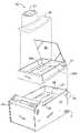
- FIG. 1is a perspective view of a thawing and heating apparatus in accordance with the present invention.
- FIG. 2is an exploded perspective view of the apparatus in FIG. 1 .
- FIG. 3is a top view of a bladder used in the apparatus in FIG. 1 .
- FIG. 4is a sectional elevational view of the apparatus in FIG. 1 .
- FIG. 5is a fragmented sectional view of an outlet on a bladder used with the apparatus in FIG. 1 .
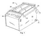
- FIG. 6is a sectional view of a portion of the thawing device in FIG. 1 during a first mode of operation.
- FIG. 7is a sectional view of a portion of the thawing device in FIG. 1 during a second mode of operation.
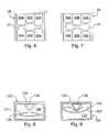
- FIG. 8is a sectional view of an alternate embodiment of the invention during a first mode of operation.
- FIG. 9is a sectional view of an alternate embodiment of the invention during a second mode of operation.
- an apparatus in accordance with the present inventionis shown and designated generally as 20 .
- the apparatus 20is operable to thaw and/or heat up biological materials that are stored at low temperatures, including but not limited to human organs, tissue and plasma.
- the apparatus 20will be described as it is used in thawing and heating frozen bags of plasma 21 .
- the apparatus 20has a generally rectangular tank 22 .
- the tank 22houses a reservoir 27 containing a fluid 28 and a system 40 that circulates fluid during the thawing process.
- the reservoir 27contains a heater 60 in contact with the fluid 28 , as shown in FIG. 4 .
- the heater 60is operable to heat the fluid 28 in the reservoir 27 to a desired temperature.
- a hollow bladder 30 having a flexible wallis disposed in the tank 22 in fluid connection with the circulation system 40 .
- the bladder 30may be placed in contact with the plasma bag 21 to be thawed.
- the circulation system 40is operable to fill the bladder and exert pressure through the bladder wall against the plasma bag 21 .
- the circulation system 40also drains fluid from the bladder to release pressure from the plasma bag 21 .
- the heated fluid 28transfers heat to the biological material to assist in thawing the biological material.
- the apparatus 20is configured to thaw the plasma bag 21 in a closed hydraulic system that keeps the bag dry. By keeping the plasma bag 21 dry, the sterility of the bag is maintained, and growth of bacteria is minimized.
- a number of bladder configurations and circulation systemsmay be used with the present invention. Referring to FIGS. 3-4 , the bladder 30 is shown with two cells in fluid connection with the circulation system 40 .
- the circulation system 40is configured to pressurize and depressurize the cells intermittently so that the cells expand and contract in different cycles. As the cells expand and contract, the bladder wall agitates the biological material to accelerate thawing.
- the tank 22has an open top end and a receptacle 26 adapted to receive a generally rectangular tray or rack 25 .
- the rack 25is configured to rest in the receptacle 26 in the top end of the tank 22 .
- the rack 25supports the bladder 30 and the plasma bag 21 above the reservoir 27 and circulation system 40 .
- the reservoir 27 in the tank 22may be filled with fluid 28 through the open receptacle 26 when the rack 25 is removed.
- the tank 22has a drain valve 41 operable to discharge fluid 28 from the reservoir 27 .
- a door or lid 29is pivotally mounted on the top side of the rack 25 .
- the lid 29is pivotal between an open position, which permits access to the interior of the rack 25 , and a closed position, which limits access to the interior of the rack.
- the lidis formed of a transparent material, such as clear plastic or other rigid material.
- the bladder 30is preferably formed of a transparent material, such as transparent polyethylene. In this way, the condition of the plasma bag 21 and bladder 30 can be observed through the lid during operation of the apparatus 20 .
- the apparatus 20may be operated by electric power, and is preferably configured to run on 120 VAC or 240 VAC.
- the bladder 30rests in the rack 25 and is placed in direct contact with the plasma bag 21 to be thawed.
- the bladder 30is configured to lay flat in the rack 25 and fold more or less in half so as to wrap around the plasma bag 21 , as shown in FIG. 4 . In this way, the bladder 30 can agitate and transfer heat to both sides of the plasma bag 21 to efficiently thaw the plasma bag.
- the interior of the bladder 30is divided into two cells 30 A and 30 B.
- the cells 30 A and 30 Bare sealed from one another by a barrier 39 that prevents fluid in one cell from entering the other cell.
- Each of the cells 30 A and 30 Bhas an inlet block 37 and an outlet block 38 .
- the inlet blockseach comprise an inlet port 32
- the outlet blocks 38each comprise an outlet port 34 .
- the inlet ports 32 and outlet ports 34are connected to the circulation system 40 through a plurality of fittings that extend through the bottom of the rack 25 .
- the fittingsare configured to connect the bladders to the rack, and connect the rack to the circulation system. A number of fitting configurations may be used to connect the bladder 30 , rack 25 and circulation system 40 .
- Air bubbles that form in the bladder 30may attach to the interior wall and reduce the liquid surface area in contact with the interior wall. Since the fluid transfers heat through the wall by contacting the interior wall, trapped air can decrease the rate of heat transfer to the plasma. Large air pockets may reduce the rate of heat transfer and significantly impede the thawing process. Therefore, the bladder 30 preferably has a mechanism for removing air bubbles that form in the bladder.
- the bladder 30has air tubes that extend within the interior of the bladder and release air that accumulates in the bladder.
- the outlet ports 34 of bladder cells 30 A and 30 Bare shown connected to one or more small diameter air tubes 35 .
- the air tubes 35are configured to bleed air from the bladder 30 and discharge the air through the outlet ports 34 as fluid drains from the bladder.
- the first cell 30 Apreferably has two air tubes to capture air from different regions within the cell.
- Each air tube 35has a small diameter inlet configured to draw air into the tube.
- the air tubes 35are operable to release air from the bladder to improve the heat transfer efficiency of the bladder. It should be understood, however, that the present invention may be practiced successfully without the use of any mechanism to remove air from the interior of the bladder 30 .
- the inlet ends of the air tubes 35are attached to the interior wall of the bladder so that the inlets are positioned toward the top of the bladder cell when the bladder is folded in the rack 25 .
- the bladder 30may be folded at the dashed line and placed in the rack so that the inlet and outlet blocks are positioned on the lower half of the bladder.
- the inlet ends of the air tubes 35extend in the upper half of the bladder to capture air bubbles.
- the tubesmay be attached to the interior wall by an adhesive tape, bonding or any other technique. In this way, the inlets are positioned near the top of the cells where air bubbles accumulate.
- the bottom of the rack 25is pitched or sloped, as shown in FIG.
- each air tube 35is connected to one of the outlet blocks to discharge air from the bladder.
- Each air tube 35extends through one of the outlet blocks 38 and connects transversely with one of the outlet ports 34 , as shown in FIG. 5 .
- the passing flowexhibits low pressure at the outlet of the air tube.
- the inlet end of the air tube 35is subject to higher pressures in the bladder 30 .
- a pressure differentialis created in the air tube. The pressure differential creates suction pressure that draws air into the tube inlet and through the tube to the tube outlet, where it is discharged through the outlet port 34 of the bladder 30 .
- the circulation system 40is configured to pump heated fluid 28 in a continuous cycle from the reservoir 27 to the bladder 30 and withdraw fluid from the bladder back to the reservoir.
- a number of hydraulic arrangementsmay be used in this invention.
- the circulation system 40has a first pump 42 configured to pump fluid 28 to the first cell 30 A and a second pump 44 configured to pump fluid to the second cell 30 B.
- the first and second pumps 42 , 44are connected to the bladder 30 by a pair of conduits 46 , 48 .
- the pumps 42 , 44each have a discharge port that connects to one of the conduits 46 , 48 .
- the conduits 46 , 48extend from the pumps and connect to inlet fittings 31 that extend through the bottom of the rack 25 .
- the inlet fittings 31extend into the interior of the rack and are configured to mate with the inlet ports 32 on the bladder 30 .
- the inlet fittings 31may mate with the inlet ports using a variety of connections.
- the inlet fittingsmay be inserted into the inlet ports and held by a friction fit connection.
- the conduits 46 , 48connect to the inlet fittings 31 on the underside of the rack 25 when the rack is placed over the tank 22 .
- the conduits 46 , 48may be formed of any suitable material.
- the conduitsare formed of flexible material, such as polyvinyl chloride tubing.
- the conduits 46 , 48preferably have a minimum of 12 inches of slack when the rack 25 is placed over the tank and connected with the conduits. In this way, the rack 25 can be lifted and maneuvered above the tank 22 without having to disconnect the conduits from the inlet fittings 31 .
- fluid 28exits the bladder cells 30 A, 30 B through the outlet ports 34 and discharges back to the reservoir 27 .
- Each outlet port 34is connected to an outlet fitting 33 that extends through the bottom of the rack 25 . Fluid is discharged from each outlet port 34 and through one of the outlet fittings 33 back to the reservoir 27 .
- a positive fluid pressureis developed in the cells. Positive pressure is created by a flow constriction component 36 connected to each of the outlet fittings 33 , as shown in FIG. 5 .
- the flow constriction components 36limit the discharge flow rate from the bladder cells.
- constriction components 36limit the discharge flow from each bladder cell to a fraction of the flow rate that enters the bladder cell, creating a net positive flow of fluid that pressurizes each cell.
- a pumpWhen a pump is activated, the cell connected to that pump expands in response to pressure created by the net positive flow.
- a pumpdeactivates, fluid flow into the cell halts, while fluid discharge through the outlet port 34 continues. As fluid in the cell drains through the outlet port, pressure in the cell is released, and the bladder wall contracts.
- the first and second pumps 42 , 44are operable in different cycles to pressurize the cells 30 A, 30 B at different intervals.
- the pumpsare operable to expand and contract the bladder cells at different intervals.
- the pumps 42 , 44are activated and deactivated by a controller 50 .
- the controller 50is configured to operate the pumps between a first mode and a second mode. In the first mode, the controller 50 activates the first pump 42 for a limited time period while the second pump 44 is deactivated. In the second mode, the controller 50 deactivates the first pump 42 and activates the second pump 44 for a limited time period. In this way, the first cell 30 A expands while the second cell 30 B contracts, and the second cell 30 B expands while the first cell 30 A contracts.
- the alternating expansion of cells 30 A, 30 Bcauses the bladder wall to oscillate as it contacts the plasma bag 21 . This gently agitates the plasma bag to assist in thawing the plasma.
- Plasma bagsare generally frozen in a solid state when in storage. As a result, most plasma bags are not in a fluid state when initially thawed and will not bend during agitation.
- the plasma bag 21is shown partially thawed in a fluid state. In this way, the effect of the alternating pump cycles may be visualized.
- the bladder 30is preferably folded over the plasma bag 21 in the apparatus 20 so that roughly one half of the bladder lies beneath the plasma bag and roughly one half of the bladder lies above the plasma bag. The bladder 30 is folded such that cell 30 A is folded over itself and cell 30 B is folded over itself. As such, cell 30 A is aligned with the side portions of the plasma bag 21 , and cell 30 B is aligned with the middle portion of the plasma bag, as shown in FIGS. 6-7 .
- the apparatusis shown operating in the first mode in which the first pump 42 is activated and the second pump 44 is deactivated.
- the cell 30 Ais expanded and cell 30 B is contracted.
- the expanded cell 30 Aexerts pressure on the side portions of the plasma bag 21 .
- contracted cell 30 Bexerts less pressure on the middle portion of the bag 21 . This creates a pressure differential in the plasma bag 21 , causing the plasma to shift from the sides of the bag toward the middle portion of the bag.
- FIG. 7the apparatus is shown operating in the second mode in which cell 30 A is contracted and cell 30 B is expanded.
- cell 30 Bexerts pressure on the middle portion of the plasma bag 21 while cell 30 A exerts less pressure on the side portions of the plasma bag.
- the circulation system 40is preferably configured to alternate evenly between the first mode and the second mode. In this way, pressure is applied to side sections of the plasma bag 21 for the same duration as the middle portion.
- the controller 50may comprise a cycle adjuster that controls the frequency in which the apparatus switches between the first mode to the second mode.
- the apparatus 20uses a closed hydraulic system to thaw plasma bags 21 in a dry environment, as stated earlier. It is desirable to maintain a dry environment in the rack 25 to minimize growth of bacteria and other contaminants. Leaks in the plasma bag 21 and/or bladder 30 will create moisture in the rack 25 . Therefore, the apparatus preferably has a moisture detection system to alert operators of moisture or leaks that are present. As stated earlier, the bottom surface of the rack 25 is shown pitched or sloped at an angle. In FIG. 4 , the bottom surface of the rack 25 is sloped toward the front of the apparatus 20 . In the event of a leak, the sloped surface is configured to drain liquid from the plasma bag 21 or bladder 30 to the front of the rack 25 .
- a moisture sensor 70is disposed at the forward end of the rack 25 near the bottom surface to detect liquid in the rack.
- the sensor 70may be wired to a signaling mechanism that alerts the operator of a possible leak.
- the signaling mechanismmay be a lamp, such as an LED, an audible alarm or other signal mechanism.
- the rack 25may have a number of compartments that permit the apparatus to thaw multiple plasma bags at the same time.
- the rack 25is shown with two compartments 25 A, 25 B that are separated by a partition.
- the partitionis configured to prevent any liquid in one compartment from entering the other compartment. In the event of a leak in one compartment, the plasma bag in the other compartment remains dry and does not need sterilization.
- the compartments 25 A, 25 Bmay be sized and configured in a number of ways to accommodate plasma bags and other items to be thawed. For example, where two compartments are used, each compartment may be sized to accommodate two 450 ml bags or one 1,000 ml bag.
- the compartments 25 A, 25 Beach have a pair of inlet fittings 31 and a pair of outlet fittings 33 .
- the two compartment rack 25has a total of four inlet fittings.
- a variety of controlsmay be provided for operating the circulation system 40 and heater.
- a central control panel 80may be mounted on the apparatus.
- the control panelmay feature a start button to activate the heater and circulation pumps and a stop button to switch off the heater and circulation pumps.
- the control panel 80may have a programmable timer configured to operate the circulation system 40 and heater 60 for a preset time. When the preset time expires, the timer switches off the circulation system 40 and heater 60 .
- the apparatusmay also have a thermostat that monitors and maintains the temperature of fluid in the reservoir to a suitable temperature for thawing the plasma bag.
- a programmable thermostatis provided to regulate the temperature of fluid to a preset temperature. For example, the thermostat may be set to 37° C.
- the thermostatmay be wired to the heater and switch the heater on when the bath falls below the desired temperature, or switch the heater off when the fluid temperature exceeds the desired temperature.
- a digital or LCD readoutmay be provided to display operating conditions in the apparatus, including elapsed heating time, temperature in the fluid reservoir, or the presence of a leak in the rack.
- the apparatusWhen the amount of fluid in the reservoir is low, the apparatus will not operate properly.
- the apparatushas a horizontal fill line marked or embossed in the interior of the tank.
- the fill lineis positioned so that an operator can visually determine how much fluid to deposit in the tank.
- the apparatuspreferably has liquid level sensor configured to contact the fluid in the reservoir when the reservoir is filled to a predetermined level.
- the sensoris connected to an alarm that activates when the fluid level drops below the predetermined level in the reservoir.
- the alarmmay include a light, audible sound or other appropriate signal to alert the operator.
- the sensormay also be configured to switch off the heater and circulation pumps when the alarm is activated.
- the lid 29preferably has a latch or other locking mechanism that secures the lid in the closed position and limits access to the interior of the rack 25 during operation of the apparatus 20 .
- the lid 29may also be equipped with an interlock mechanism that prevents operation of the apparatus if the lid is not closed.
- a number of componentscan be used to form the interlock.
- a magnetmay be mounted on the lid 29 and linked to a sensor in the tank 22 .
- the sensoris positioned in the tank 22 to detect the magnetic field when the lid is in the closed position.
- the sensoris configured to interlock the apparatus when the magnetic field is not detected. In this way, the circulation system 40 and heater 60 can not be started when the lid 29 is open. Moreover, the circulation system 40 and heater 60 can be automatically shut off if the lid 29 is opened during operation of the apparatus 20 .
- the apparatus 20may be used to heat materials to various temperatures for different applications. As described earlier, the apparatus 20 may be programmed to heat plasma to a temperature of 37° C., which is compatible with human body temperature. Alternatively, the apparatus 20 may be used to heat and maintain materials to temperatures that are below ambient temperature. For example, the apparatus 20 may be used to maintain the temperature of materials at 6° C., well below room temperature.
- the tank 22is connected to a separate chilling device. Fluid in the reservoir is pumped out of the tank 22 and circulated through the chilling device to lower the fluid temperature to 1° C. The chilled fluid is then cycled back to the reservoir where the heater 60 raises the temperature of the fluid to 6° C. The fluid in the reservoir is maintained at 6° C. by recirculating a portion of the fluid bath through the chilling device and heating the return flow in the reservoir so that the bath remains at 6° C.
- the fluid reservoir 27is exposed to air that enters and leaves the tank 22 .
- the displacement of fluidcauses air to enter the reservoir area. Dust or other contaminants in the air can contaminate the fluid 28 and build up in the reservoir 27 .
- the apparatus 20preferably has an air filter 72 that filters air entering the reservoir 27 from outside the tank 22 .
- the apparatus 20may include a 0.3 micron filter 72 that captures dusts and other contaminants in the surrounding air. By filtering air that enters the tank 22 , accumulation of dust or contaminants in the reservoir is reduced.
- the air filter 72decreases the need for periodic cleaning and sterilization of the reservoir 27 .
- FIGS. 8-9a second embodiment of the invention is shown using upper and lower bladders 130 , 131 in a rack 125 .
- the upper and lower bladders 130 , 131are placed above and below a plasma bag 121 , respectively.
- the rack 125has a lid 129 with a rigid projection or hub 138 that extends inwardly and bears against the upper bladder 130 when the lid is closed.
- the bladders 130 , 131are each connected to separate circulation pumps that are operable to expand and contract the bladders at different intervals. As in the previous embodiment, the pumps operate in a first mode and a second mode, and each bladder drains fluid to a fluid reservoir in the apparatus.
- a first pumpfills the upper bladder 130 with fluid while the lower bladder 131 is drained.
- a second pumpfills the lower bladder 131 while the upper bladder 130 is drained.
- the plasma bag 121is compressed downwardly against the lower bladder 131 , as shown in FIG. 8 .
- the lower bladder 131is pressurized, the plasma bag is compressed upwardly against the upper bladder 130 , as shown in FIG. 9 .
- the upper bladder 130exerts less pressure on the plasma bag than the lower bladder 131 and therefore yields in response to the pressure exerted by the lower bladder 131 .
- the upper bladder 130 and plasma bagAs the upper bladder 130 and plasma bag are compressed upwardly, the upper bladder and plasma bag bend upwardly against the curved hub. As a result, operation of the pumps between the first and second modes bends the plasma bag upwardly and downwardly in a continuous cycle to agitate the plasma.
- the tank 22is placed on a level surface, and the rack is disconnected from any conduits or tubing beneath the rack.
- the rack 25is then removed from the receptacle on the top of the tank so that the top of the tank is open and the reservoir 27 is exposed.
- the reservoir 27is filled with tap water, deionized water or other appropriate fluid. If deionized water is used, a source of ions, such as salt, should be added to the water to make the water conductive. In this way, the water level sensor in the reservoir 27 can monitor the water level and detect when the water level is low. If desired, a chemical additive to limit algae growth may also be added to the fluid 28 .
- the rackis held above the tank 22 , and the conduits 46 , 48 are connected to the inlet fittings 31 on the underside of the rack 25 .
- the rack 25is then lowered into the receptacle on the tank 22 .
- One or more bladders 30are then connected to the rack. Specifically, a bladder 30 is placed in each of the compartments.
- the inlet fittings 31are connected to the inlet ports 32 on the bladders 30 , and the outlet fittings 33 are connected to the outlet ports on the bladders.
- the lid 29 on the rack 25is pivoted to the closed position and latched.
- the tankis then connected to a power source, and the apparatus 20 is switched on.
- the heater 60is activated to heat the fluid 28 in the reservoir 27 to the desired temperature.
- One or both of the circulation pumps 42 , 44are activated to circulate the fluid in the reservoir.
- the heater 60is switched off, and the lid 29 on the rack 25 is unlatched and opened.
- One or more plasma bags 21are taken out of storage and placed on the bladders in the rack 25 .
- the bladders 30are preferably folded around the plasma bags 21 so that each bladder is wrapped around a plasma bag and contacts top and bottom sides of the plasma bag.
- the lid 29 on the rack 25is then pivoted to the closed position and latched.
- Both circulation pumps 42 , 44circulate the fluid through the bladder to begin thawing the plasma bags. If a programmable timer is provided, the timer is adjusted to set a desired thawing time.
- the circulation system 40continues operate until the programmed time expires.
- the controller 50regulates the operation of the circulation pumps 42 , 44 so that the bladder cells expand and contract at different intervals.
- the first circulation pump 42fills the first cell 30 A of a bladder with heated fluid. A portion of the incoming flow exits through the outlet port 34 of the first cell 30 A and discharges back to the reservoir 27 through a constriction component 36 .
- the incoming flow rate in the first cell 30 Ais greater than the discharge flow rate, creating a net positive flow of fluid 28 in the cell.
- the first cell 30 Afills to capacity with fluid 28 and becomes pressurized.
- the bladder wall surrounding the first cellexpands against the plasma bag 21 .
- the controller 50then deactivates the first circulation pump 42 and activates the second circulation pump 44 . Fluid in the first cell 30 A continues to discharge through the outlet port 34 to the reservoir 27 , releasing pressure in the first cell. As pressure in the first cell 30 A is released, the bladder wall retracts, releasing pressure from the plasma bag 21 .
- the second bladder cell 30 Bfills with fluid 28 so that the bladder wall surrounding the second cell expands against the plasma bag 21 .
- a portion of the incoming flowexits through the outlet port 34 of the second cell and discharges back to the reservoir 27 through a constriction component 36 .
- the incoming flow rate in the second cell 30 Bis greater than the discharge flow rate, creating a net positive flow of fluid in the cell.
- the second cell 30 Bfills with fluid and becomes pressurized.
- the bladder wall surrounding the second cellexpands against the plasma bag 21 , similar to the first cell 30 A.
- the controller 50deactivates the second circulation pump 44 after the second cell 30 B is filled.
- Fluid in the second cell 30 Bcontinues to discharge through the outlet port 34 , releasing pressure in the second cell.
- the bladder wallretracts, releasing pressure from the plasma bag 21 .
- the controller 50activates the first circulation pump 42 , and the cycle is repeated with the first bladder cell 30 A.
- the alternating expansion and contraction of the bladder cells 30 A, 30 Bcauses the bladder wall to massage the plasma bag 21 .
- the moving bladdergently agitates the plasma bag 21 to assist in thawing the plasma.
- the thawing processcan be observed by looking through the transparent lid 29 and transparent bladders.
- the circulation pumps 42 , 44operate until the preset time expires on the control panel. As time expires, the circulation system 40 shuts off. If the plasma bag 21 still appears partially frozen, the circulation system 40 may be restarted to thaw the plasma for an additional amount of time. The thawing cycle may be terminated manually before the programmed time expires by pressing a stop button on the control panel. Once the pumps 42 , 44 are stopped, fluid in the bladders drains back to the reservoir 27 and pressure is released from the plasma bags 21 . In addition, if the heater 60 is running, the heater is shut off.
Landscapes
- Life Sciences & Earth Sciences (AREA)
- Health & Medical Sciences (AREA)
- Engineering & Computer Science (AREA)
- Dentistry (AREA)
- General Health & Medical Sciences (AREA)
- Wood Science & Technology (AREA)
- Zoology (AREA)
- Environmental Sciences (AREA)
- Medical Preparation Storing Or Oral Administration Devices (AREA)
- External Artificial Organs (AREA)
Abstract
Description
Claims (35)
Priority Applications (1)
| Application Number | Priority Date | Filing Date | Title |
|---|---|---|---|
| US10/268,610US7722839B2 (en) | 2001-10-11 | 2002-10-10 | Apparatus and method for thawing biological materials |
Applications Claiming Priority (2)
| Application Number | Priority Date | Filing Date | Title |
|---|---|---|---|
| US32854501P | 2001-10-11 | 2001-10-11 | |
| US10/268,610US7722839B2 (en) | 2001-10-11 | 2002-10-10 | Apparatus and method for thawing biological materials |
Publications (2)
| Publication Number | Publication Date |
|---|---|
| US20030082069A1 US20030082069A1 (en) | 2003-05-01 |
| US7722839B2true US7722839B2 (en) | 2010-05-25 |
Family
ID=26953206
Family Applications (1)
| Application Number | Title | Priority Date | Filing Date |
|---|---|---|---|
| US10/268,610Expired - Fee RelatedUS7722839B2 (en) | 2001-10-11 | 2002-10-10 | Apparatus and method for thawing biological materials |
Country Status (1)
| Country | Link |
|---|---|
| US (1) | US7722839B2 (en) |
Cited By (15)
| Publication number | Priority date | Publication date | Assignee | Title |
|---|---|---|---|---|
| US20120095441A1 (en)* | 2009-06-15 | 2012-04-19 | National University Of Ireland, Galway | Stem cell delivery device for orthobiologics applications |
| WO2015054605A1 (en)* | 2013-10-11 | 2015-04-16 | SonaCare Medical, LLC | Focused ultrasound treatment using fluid bladder |
| US20150125138A1 (en)* | 2012-10-31 | 2015-05-07 | Pluristem Ltd. | Method and device for thawing biological material |
| US9127246B2 (en) | 2010-02-22 | 2015-09-08 | Life Technologies Corporation | Methods for condensing a humid gas |
| US9173248B2 (en) | 2011-03-14 | 2015-10-27 | Products Support, Inc. | Thawing oven |
| US20160106624A1 (en)* | 2013-05-07 | 2016-04-21 | Biosafe S.A. | Mixing System for Mixing Biological Specimens with Additives |
| US9457306B2 (en) | 2014-10-07 | 2016-10-04 | Life Technologies Corporation | Regulated vacuum off-gassing of gas filter for fluid processing system and related methods |
| US9576619B2 (en) | 2011-10-27 | 2017-02-21 | Hewlett Packard Enterprise Development Lp | Shiftable memory supporting atomic operation |
| US9974983B2 (en) | 2015-11-12 | 2018-05-22 | SonaCare Medical, LLC | Tissue stabilization for therapeutic ultrasound |
| US10005005B2 (en) | 2014-03-21 | 2018-06-26 | Life Technologies Corporation | Condenser systems for fluid processing systems |
| US20190336660A1 (en)* | 2018-05-07 | 2019-11-07 | Fremon Scientific, Inc. | Thawing biological substances |
| US10576190B2 (en) | 2014-08-08 | 2020-03-03 | Fremon Scientific, Inc. | Smart bag used in sensing physiological and/or physical parameters of bags containing biological substance |
| US10688429B2 (en) | 2014-03-21 | 2020-06-23 | Life Technologies Corporation | Gas filter systems for fluid processing systems |
| US11221281B2 (en)* | 2016-03-21 | 2022-01-11 | Xiamen Talent Biomedical Technology Company, Ltd. | Heat treatment device for slide specimen testing |
| US11268056B2 (en) | 2015-12-29 | 2022-03-08 | Life Technologies Corporation | Flexible bioprocessing container with partial dividing partition |
Families Citing this family (21)
| Publication number | Priority date | Publication date | Assignee | Title |
|---|---|---|---|---|
| US7377686B2 (en)* | 2003-09-04 | 2008-05-27 | Millipore Corporation | Disposable mixing system |
| US20050063247A1 (en)* | 2003-09-22 | 2005-03-24 | Krause Richard James | Biobag undulating mixing system |
| DE10354109A1 (en)* | 2003-11-19 | 2005-06-23 | Bayer Technology Services Gmbh | Process for melting frozen, hydrous products |
| US8012416B2 (en)* | 2005-08-30 | 2011-09-06 | Cytotherm, L.P. | Thawing biological material using a sealed liquid bladder |
| US8684600B2 (en)* | 2006-04-28 | 2014-04-01 | Restaurant Technology, Inc. | Temperature controlled fluid bath food holding device |
| US7594582B2 (en)* | 2006-04-28 | 2009-09-29 | Restaurant Technology, Inc. | Temperature controlled fluid bath food holding apparatus |
| US20070253647A1 (en)* | 2006-04-28 | 2007-11-01 | Restaurant Technology, Inc. | Temperature controlled fluid bath food holding device and method |
| US20100178223A1 (en)* | 2007-10-23 | 2010-07-15 | Angela Adinah Roberts | (Roberts) plasma waterbath |
| US8152116B2 (en)* | 2008-02-27 | 2012-04-10 | Baxter International Inc. | Dialysate bag seal breakage sensor incorporated in dialysate bag management |
| KR101007835B1 (en)* | 2008-03-10 | 2011-01-13 | 윤근진 | Blood thawing device |
| US8058057B2 (en)* | 2008-05-30 | 2011-11-15 | Corning Incorporated | Cell culture apparatus and method |
| KR101509767B1 (en)* | 2009-02-11 | 2015-04-06 | 엘지전자 주식회사 | Microwave oven combined with hood |
| WO2015068127A1 (en)* | 2013-11-08 | 2015-05-14 | Novasyst Inc. | Frozen food thawing |
| FR3012980B1 (en)* | 2013-11-13 | 2015-11-13 | Interscience | LABORATORY MIXER |
| US10196598B2 (en)* | 2014-10-07 | 2019-02-05 | Cpsi Holdings Llc | System for heating and cooling samples |
| KR101636340B1 (en)* | 2015-01-20 | 2016-07-20 | 윤근진 | The blood thawing apparatus and contorl method using the same |
| CN105477698A (en)* | 2015-08-07 | 2016-04-13 | 常州华岳微创医疗器械有限公司 | Combined plasma thawing apparatus |
| US10864333B2 (en) | 2016-04-01 | 2020-12-15 | Enthermics Medical Systems | Medical liquid warmer with auxiliary temperature sensor |
| CN107881101A (en)* | 2017-11-21 | 2018-04-06 | 赛慕特生物工程(上海)有限公司 | One kind rubs formula cell cryopreservation bag dry type recovery instrument |
| US11712321B2 (en)* | 2018-11-15 | 2023-08-01 | Asp Global Manufacturing Gmbh | Apparatus and method for adjusting a volume of a basin of a treatment apparatus |
| CN116045516B (en)* | 2022-12-19 | 2025-09-05 | 青岛海尔生物医疗科技有限公司 | Melting Machine |
Citations (17)
| Publication number | Priority date | Publication date | Assignee | Title |
|---|---|---|---|---|
| US2845929A (en)* | 1953-04-30 | 1958-08-05 | Max M Strumia | Apparatus for the collection and cooling of blood |
| US3518393A (en) | 1967-11-21 | 1970-06-30 | South African Inventions | Bloodwarmers |
| US4486389A (en) | 1982-06-28 | 1984-12-04 | Cryosan, Inc. | Frozen plasma thawing system |
| US4539005A (en)* | 1983-10-24 | 1985-09-03 | Greenblatt Gordon M | Blood infusion apparatus and method |
| US4808159A (en)* | 1987-03-16 | 1989-02-28 | Minnesota Mining And Manufacturing Company | Apparatus and method for admixture blood warming |
| DE3741051C1 (en) | 1987-12-04 | 1989-06-01 | Volker Barkey | Thawing and tempering device for medical products |
| US5147330A (en) | 1989-10-18 | 1992-09-15 | Ljungberg & Kogel | Blood cradle |
| US5243833A (en) | 1991-11-08 | 1993-09-14 | Instacool Inc. Of North America | Device for thawing frozen transfusion material and method therefore |
| US5282264A (en)* | 1991-07-01 | 1994-01-25 | Reeves William R | Apparatus for thawing and warming fluids for intravenous administration utilizing heater air recirculation |
| US5403279A (en)* | 1988-06-29 | 1995-04-04 | Terumo Kabushiki Kaisha | Blood collecting apparatus |
| US5645194A (en)* | 1992-03-16 | 1997-07-08 | U.S. Medical, Inc. | System for filling medical nutrition containers |
| US5733263A (en)* | 1994-09-20 | 1998-03-31 | Cabot Technology Corporation | Thermal retention system and method |
| US5743878A (en)* | 1991-06-25 | 1998-04-28 | Medication Delivery Devices, Inc. | Infusion pump, treatment fluid bag therefor, and method for the use thereof |
| US5779974A (en) | 1995-10-30 | 1998-07-14 | Kuzyk; Roman | Frozen plasma thawing system |
| US6336003B1 (en)* | 2000-09-01 | 2002-01-01 | Automatic Medical Technologies, Inc. | Max one I.V. warmer |
| US6748164B1 (en)* | 2000-10-31 | 2004-06-08 | Photo-Therm, L.P. | Plasma thawing system |
| US6824528B1 (en)* | 1997-03-03 | 2004-11-30 | Medical Solutions, Inc. | Method and apparatus for pressure infusion and temperature control of infused liquids |
- 2002
- 2002-10-10USUS10/268,610patent/US7722839B2/ennot_activeExpired - Fee Related
Patent Citations (19)
| Publication number | Priority date | Publication date | Assignee | Title |
|---|---|---|---|---|
| US2845929A (en)* | 1953-04-30 | 1958-08-05 | Max M Strumia | Apparatus for the collection and cooling of blood |
| US3518393A (en) | 1967-11-21 | 1970-06-30 | South African Inventions | Bloodwarmers |
| US4486389A (en) | 1982-06-28 | 1984-12-04 | Cryosan, Inc. | Frozen plasma thawing system |
| US4539005A (en)* | 1983-10-24 | 1985-09-03 | Greenblatt Gordon M | Blood infusion apparatus and method |
| US4808159A (en)* | 1987-03-16 | 1989-02-28 | Minnesota Mining And Manufacturing Company | Apparatus and method for admixture blood warming |
| DE3741051C1 (en) | 1987-12-04 | 1989-06-01 | Volker Barkey | Thawing and tempering device for medical products |
| EP0318924B1 (en) | 1987-12-04 | 1992-03-18 | Volker Barkey | Thawing and warming-up device for medical products |
| US5403279A (en)* | 1988-06-29 | 1995-04-04 | Terumo Kabushiki Kaisha | Blood collecting apparatus |
| US5147330A (en) | 1989-10-18 | 1992-09-15 | Ljungberg & Kogel | Blood cradle |
| US5743878A (en)* | 1991-06-25 | 1998-04-28 | Medication Delivery Devices, Inc. | Infusion pump, treatment fluid bag therefor, and method for the use thereof |
| US5282264A (en)* | 1991-07-01 | 1994-01-25 | Reeves William R | Apparatus for thawing and warming fluids for intravenous administration utilizing heater air recirculation |
| US5243833A (en) | 1991-11-08 | 1993-09-14 | Instacool Inc. Of North America | Device for thawing frozen transfusion material and method therefore |
| US5645194A (en)* | 1992-03-16 | 1997-07-08 | U.S. Medical, Inc. | System for filling medical nutrition containers |
| US5733263A (en)* | 1994-09-20 | 1998-03-31 | Cabot Technology Corporation | Thermal retention system and method |
| US5779974A (en) | 1995-10-30 | 1998-07-14 | Kuzyk; Roman | Frozen plasma thawing system |
| US6007773A (en) | 1995-10-30 | 1999-12-28 | Kuzyk; Roman | Frozen plasma thawing system |
| US6824528B1 (en)* | 1997-03-03 | 2004-11-30 | Medical Solutions, Inc. | Method and apparatus for pressure infusion and temperature control of infused liquids |
| US6336003B1 (en)* | 2000-09-01 | 2002-01-01 | Automatic Medical Technologies, Inc. | Max one I.V. warmer |
| US6748164B1 (en)* | 2000-10-31 | 2004-06-08 | Photo-Therm, L.P. | Plasma thawing system |
Non-Patent Citations (6)
| Title |
|---|
| Barkey, TCS Infusion Warming Concepts, phasmaterm, 3 page web advertisement. |
| Labor Technik Barkey, plasmatherm, 4 page advertisement. |
| Photo-Therm, Plasma Thawing System-Cyto-therm CT S, 2 page advertisement. |
| Photo-Therm, Plasma Thawing System-Cyto-Therm III T, 2 page advertisement. |
| Thermogenesis, Plasma Thawers, "Simply the Best", 3 page advertisement. |
| Transmed®, "New: Thawing of Stem Cell Preparations with Sahara-TSC", 1 page advertisement. |
Cited By (42)
| Publication number | Priority date | Publication date | Assignee | Title |
|---|---|---|---|---|
| US8992473B2 (en)* | 2009-06-15 | 2015-03-31 | National University Of Ireland, Galway | Stem cell delivery device for orthobiologics applications |
| US20120095441A1 (en)* | 2009-06-15 | 2012-04-19 | National University Of Ireland, Galway | Stem cell delivery device for orthobiologics applications |
| US9528083B2 (en) | 2010-02-22 | 2016-12-27 | Life Technologies Corporation | Heat exchanger system with flexible bag |
| US12012579B2 (en) | 2010-02-22 | 2024-06-18 | Life Technologies Corporation | Heat exchanger system with flexible bag |
| US11492582B2 (en) | 2010-02-22 | 2022-11-08 | Life Technologies Corporation | Heat exchanger system with flexible bag |
| US9127246B2 (en) | 2010-02-22 | 2015-09-08 | Life Technologies Corporation | Methods for condensing a humid gas |
| US9284524B2 (en) | 2010-02-22 | 2016-03-15 | Life Technologies Corporation | Heat exchanger system with flexible bag |
| US10711233B2 (en) | 2010-02-22 | 2020-07-14 | Life Technologies Corporation | Heat exchanger system with flexible bag |
| US9173248B2 (en) | 2011-03-14 | 2015-10-27 | Products Support, Inc. | Thawing oven |
| US9576619B2 (en) | 2011-10-27 | 2017-02-21 | Hewlett Packard Enterprise Development Lp | Shiftable memory supporting atomic operation |
| US20150125138A1 (en)* | 2012-10-31 | 2015-05-07 | Pluristem Ltd. | Method and device for thawing biological material |
| US10251389B2 (en)* | 2012-10-31 | 2019-04-09 | Pluristem Ltd. | Method and device for thawing biological material |
| US11918541B2 (en) | 2013-05-07 | 2024-03-05 | Biosafe S.A. | Fluid processing based on inflatable bags, mixing system, and method of use thereof |
| US11077020B2 (en)* | 2013-05-07 | 2021-08-03 | Biosafe S.A. | Fluid processing based on inflatable bags, mixing system, and method of use thereof |
| US20160106624A1 (en)* | 2013-05-07 | 2016-04-21 | Biosafe S.A. | Mixing System for Mixing Biological Specimens with Additives |
| US10029126B2 (en) | 2013-10-11 | 2018-07-24 | SonaCare Medical, LLC | System and method of delivering focused ultrasound treatment using a variable volume fluid bladder |
| WO2015054605A1 (en)* | 2013-10-11 | 2015-04-16 | SonaCare Medical, LLC | Focused ultrasound treatment using fluid bladder |
| US11717768B2 (en) | 2014-03-21 | 2023-08-08 | Life Technologies Corporation | Condenser bag for processing a fluid |
| US10688429B2 (en) | 2014-03-21 | 2020-06-23 | Life Technologies Corporation | Gas filter systems for fluid processing systems |
| US12076681B2 (en) | 2014-03-21 | 2024-09-03 | Life Technologies Corporation | Methods for gas filtration in fluid processing systems |
| US10005005B2 (en) | 2014-03-21 | 2018-06-26 | Life Technologies Corporation | Condenser systems for fluid processing systems |
| US11554335B2 (en) | 2014-03-21 | 2023-01-17 | Life Technologies Corporation | Methods for gas filteration in fluid processing systems |
| US12285713B2 (en) | 2014-03-21 | 2025-04-29 | Life Technologies Corporation | Condenser bag for processing a fluid |
| US11229855B2 (en) | 2014-03-21 | 2022-01-25 | Life Technologies Corporation | Condenser systems for processing a fluid |
| US10576190B2 (en) | 2014-08-08 | 2020-03-03 | Fremon Scientific, Inc. | Smart bag used in sensing physiological and/or physical parameters of bags containing biological substance |
| US10722623B2 (en) | 2014-08-08 | 2020-07-28 | Fremon Scientific, Inc. | Smart bag used in sensing physiological and/or physical parameters of bags containing biological substance |
| US11685886B2 (en) | 2014-10-07 | 2023-06-27 | Life Technologies Corporation | Regulated vacuum off-gassing of gas filter for fluid processing system and related methods |
| US10059916B2 (en) | 2014-10-07 | 2018-08-28 | Life Technologies Corporation | Regulated vacuum off-gassing of gas filter for fluid processing system and related methods |
| US10822582B2 (en) | 2014-10-07 | 2020-11-03 | Life Technologies Corporation | Regulated vacuum off-gassing of gas filter for fluid processing system and related methods |
| US12188000B2 (en) | 2014-10-07 | 2025-01-07 | Life Technologies Corporation | Regulated vacuum off-gassing of gas filter for fluid processing system and related methods |
| US9457306B2 (en) | 2014-10-07 | 2016-10-04 | Life Technologies Corporation | Regulated vacuum off-gassing of gas filter for fluid processing system and related methods |
| US9974983B2 (en) | 2015-11-12 | 2018-05-22 | SonaCare Medical, LLC | Tissue stabilization for therapeutic ultrasound |
| US11268056B2 (en) | 2015-12-29 | 2022-03-08 | Life Technologies Corporation | Flexible bioprocessing container with partial dividing partition |
| US12226561B2 (en) | 2015-12-29 | 2025-02-18 | Life Technologies Corporation | Magnetic particle separation system with flexible bioprocessing container |
| US11221281B2 (en)* | 2016-03-21 | 2022-01-11 | Xiamen Talent Biomedical Technology Company, Ltd. | Heat treatment device for slide specimen testing |
| US10816446B2 (en) | 2018-05-07 | 2020-10-27 | Fremon Scientific, Inc. | Thawing biological substances |
| US10499458B2 (en) | 2018-05-07 | 2019-12-03 | Fremon Scientific, Inc. | Thawing biological substances |
| US20190336660A1 (en)* | 2018-05-07 | 2019-11-07 | Fremon Scientific, Inc. | Thawing biological substances |
| US10732083B2 (en) | 2018-05-07 | 2020-08-04 | Fremon Scientific, Inc. | Thawing biological substances |
| US10866173B2 (en)* | 2018-05-07 | 2020-12-15 | Fremon Scientific, Inc. | Thawing biological substances |
| US11448575B2 (en) | 2018-05-07 | 2022-09-20 | Fremon Scientific, Inc. | Thawing biological substances |
| US10837885B2 (en) | 2018-05-07 | 2020-11-17 | Fremon Scientific, Inc. | Thawing biological substances |
Also Published As
| Publication number | Publication date |
|---|---|
| US20030082069A1 (en) | 2003-05-01 |
Similar Documents
| Publication | Publication Date | Title |
|---|---|---|
| US7722839B2 (en) | Apparatus and method for thawing biological materials | |
| JP6955607B2 (en) | Methods and dialysis systems for removing air or other undissolved gas from the blood flow in the dialysis unit | |
| EP2246080B1 (en) | An extracorporeal blood flow system | |
| US7011742B2 (en) | Blood product transfer system | |
| JP7251894B2 (en) | device | |
| JP5624599B2 (en) | Apparatus and method for heat exchange from improved body | |
| JP6838820B2 (en) | Dialysis monitor and operation method | |
| CN105026304A (en) | water dispenser | |
| ES2899671T3 (en) | Device for thawing frozen plasma bags | |
| JP6903406B2 (en) | Extracorporeal blood purification system with integrated disinfection case | |
| CA2459716C (en) | Blood product transfer system | |
| JPH0929015A (en) | Circulating bath hot water device and method for supplying circulating bath hot water |
Legal Events
| Date | Code | Title | Description |
|---|---|---|---|
| AS | Assignment | Owner name:PHOTOTHERM LP, NEW JERSEY Free format text:ASSIGNMENT OF ASSIGNORS INTEREST;ASSIGNOR:KUZYK, ROMAN;REEL/FRAME:013640/0207 Effective date:20021209 Owner name:PHOTOTHERM LP,NEW JERSEY Free format text:ASSIGNMENT OF ASSIGNORS INTEREST;ASSIGNOR:KUZYK, ROMAN;REEL/FRAME:013640/0207 Effective date:20021209 | |
| AS | Assignment | Owner name:CYTOTHERM, L.P., NEW JERSEY Free format text:CHANGE OF NAME;ASSIGNOR:KUZYK, ROMAN;REEL/FRAME:021158/0614 Effective date:20041130 Owner name:CYTOTHERM, L.P.,NEW JERSEY Free format text:CHANGE OF NAME;ASSIGNOR:KUZYK, ROMAN;REEL/FRAME:021158/0614 Effective date:20041130 | |
| FEPP | Fee payment procedure | Free format text:PAYOR NUMBER ASSIGNED (ORIGINAL EVENT CODE: ASPN); ENTITY STATUS OF PATENT OWNER: SMALL ENTITY | |
| STCF | Information on status: patent grant | Free format text:PATENTED CASE | |
| FPAY | Fee payment | Year of fee payment:4 | |
| MAFP | Maintenance fee payment | Free format text:PAYMENT OF MAINTENANCE FEE, 8TH YR, SMALL ENTITY (ORIGINAL EVENT CODE: M2552) Year of fee payment:8 | |
| FEPP | Fee payment procedure | Free format text:MAINTENANCE FEE REMINDER MAILED (ORIGINAL EVENT CODE: REM.); ENTITY STATUS OF PATENT OWNER: SMALL ENTITY | |
| LAPS | Lapse for failure to pay maintenance fees | Free format text:PATENT EXPIRED FOR FAILURE TO PAY MAINTENANCE FEES (ORIGINAL EVENT CODE: EXP.); ENTITY STATUS OF PATENT OWNER: SMALL ENTITY | |
| STCH | Information on status: patent discontinuation | Free format text:PATENT EXPIRED DUE TO NONPAYMENT OF MAINTENANCE FEES UNDER 37 CFR 1.362 | |
| FP | Lapsed due to failure to pay maintenance fee | Effective date:20220525 |