US7722652B2 - Pivoting joints for spinal implants including designed resistance to motion and methods of use - Google Patents
Pivoting joints for spinal implants including designed resistance to motion and methods of useDownload PDFInfo
- Publication number
- US7722652B2 US7722652B2US11/341,188US34118806AUS7722652B2US 7722652 B2US7722652 B2US 7722652B2US 34118806 AUS34118806 AUS 34118806AUS 7722652 B2US7722652 B2US 7722652B2
- Authority
- US
- United States
- Prior art keywords
- anchor
- cavity
- connector
- wear
- channel
- Prior art date
- Legal status (The legal status is an assumption and is not a legal conclusion. Google has not performed a legal analysis and makes no representation as to the accuracy of the status listed.)
- Active, expires
Links
Images


Classifications
- A—HUMAN NECESSITIES
- A61—MEDICAL OR VETERINARY SCIENCE; HYGIENE
- A61B—DIAGNOSIS; SURGERY; IDENTIFICATION
- A61B17/00—Surgical instruments, devices or methods
- A61B17/56—Surgical instruments or methods for treatment of bones or joints; Devices specially adapted therefor
- A61B17/58—Surgical instruments or methods for treatment of bones or joints; Devices specially adapted therefor for osteosynthesis, e.g. bone plates, screws or setting implements
- A61B17/68—Internal fixation devices, including fasteners and spinal fixators, even if a part thereof projects from the skin
- A61B17/70—Spinal positioners or stabilisers, e.g. stabilisers comprising fluid filler in an implant
- A61B17/7001—Screws or hooks combined with longitudinal elements which do not contact vertebrae
- A61B17/7035—Screws or hooks, wherein a rod-clamping part and a bone-anchoring part can pivot relative to each other
- A—HUMAN NECESSITIES
- A61—MEDICAL OR VETERINARY SCIENCE; HYGIENE
- A61B—DIAGNOSIS; SURGERY; IDENTIFICATION
- A61B17/00—Surgical instruments, devices or methods
- A61B17/56—Surgical instruments or methods for treatment of bones or joints; Devices specially adapted therefor
- A61B17/58—Surgical instruments or methods for treatment of bones or joints; Devices specially adapted therefor for osteosynthesis, e.g. bone plates, screws or setting implements
- A61B17/68—Internal fixation devices, including fasteners and spinal fixators, even if a part thereof projects from the skin
- A61B17/70—Spinal positioners or stabilisers, e.g. stabilisers comprising fluid filler in an implant
- A61B17/7001—Screws or hooks combined with longitudinal elements which do not contact vertebrae
- A61B17/7002—Longitudinal elements, e.g. rods
- A61B17/7011—Longitudinal element being non-straight, e.g. curved, angled or branched
- A—HUMAN NECESSITIES
- A61—MEDICAL OR VETERINARY SCIENCE; HYGIENE
- A61B—DIAGNOSIS; SURGERY; IDENTIFICATION
- A61B17/00—Surgical instruments, devices or methods
- A61B17/56—Surgical instruments or methods for treatment of bones or joints; Devices specially adapted therefor
- A61B17/58—Surgical instruments or methods for treatment of bones or joints; Devices specially adapted therefor for osteosynthesis, e.g. bone plates, screws or setting implements
- A61B17/68—Internal fixation devices, including fasteners and spinal fixators, even if a part thereof projects from the skin
- A61B17/70—Spinal positioners or stabilisers, e.g. stabilisers comprising fluid filler in an implant
- A61B17/7001—Screws or hooks combined with longitudinal elements which do not contact vertebrae
- A61B17/7032—Screws or hooks with U-shaped head or back through which longitudinal rods pass
- A—HUMAN NECESSITIES
- A61—MEDICAL OR VETERINARY SCIENCE; HYGIENE
- A61B—DIAGNOSIS; SURGERY; IDENTIFICATION
- A61B17/00—Surgical instruments, devices or methods
- A61B17/56—Surgical instruments or methods for treatment of bones or joints; Devices specially adapted therefor
- A61B17/58—Surgical instruments or methods for treatment of bones or joints; Devices specially adapted therefor for osteosynthesis, e.g. bone plates, screws or setting implements
- A61B17/68—Internal fixation devices, including fasteners and spinal fixators, even if a part thereof projects from the skin
- A61B17/70—Spinal positioners or stabilisers, e.g. stabilisers comprising fluid filler in an implant
- A61B17/7055—Spinal positioners or stabilisers, e.g. stabilisers comprising fluid filler in an implant connected to sacrum, pelvis or skull
- Y—GENERAL TAGGING OF NEW TECHNOLOGICAL DEVELOPMENTS; GENERAL TAGGING OF CROSS-SECTIONAL TECHNOLOGIES SPANNING OVER SEVERAL SECTIONS OF THE IPC; TECHNICAL SUBJECTS COVERED BY FORMER USPC CROSS-REFERENCE ART COLLECTIONS [XRACs] AND DIGESTS
- Y10—TECHNICAL SUBJECTS COVERED BY FORMER USPC
- Y10T—TECHNICAL SUBJECTS COVERED BY FORMER US CLASSIFICATION
- Y10T29/00—Metal working
- Y10T29/49—Method of mechanical manufacture
- Y10T29/49826—Assembling or joining
- Y10T29/49863—Assembling or joining with prestressing of part
Definitions
- Longitudinal memberssuch as spinal rods
- spinal rodsare often used in the surgical treatment of spinal disorders such as degenerative disc disease, disc herniations, scoliosis or other curvature abnormalities, and fractures.
- spinal fusionis indicated to inhibit relative motion between vertebral bodies.
- dynamic implantsare used to preserve motion between vertebral bodies.
- longitudinal membersmay be attached to the exterior of two or more vertebrae, whether it is at a posterior, anterior, or lateral side of the vertebrae. In other embodiments, longitudinal members are attached to the vertebrae without the use of dynamic implants or spinal fusion.
- Longitudinal membersmay provide a stable, rigid column that encourages bones to fuse after spinal-fusion surgery. Further, the longitudinal members may redirect stresses over a wider area away from a damaged or defective region. Also, rigid longitudinal members may restore the spine to its proper alignment. In some cases, flexible longitudinal members may be appropriate. Flexible longitudinal members may provide other advantages, such as increasing loading on interbody constructs, decreasing stress transfer to adjacent vertebral elements while bone-graft healing takes place, and generally balancing strength with flexibility.
- clamping devicesConventionally, longitudinal members are secured to vertebral members using rigid clamping devices. These clamping devices may be multi-axial in the sense that they are adjustable prior to securing. However, once secured, the clamping devices are locked in place. A surgeon may wish to implant a flexible rod system and have more freedom to control pivot points or the nature of the pivoting motion. At present, a surgeon might only have a choice between rigid and flexible longitudinal members, which may not necessarily provide the desired degree of flexibility.
- Illustrative embodiments disclosed hereinare directed to a pivoting connector that couples a vertebral member to a longitudinal member.
- An anchoris pivotally attaching to a body by positioning a head of the anchor within a cavity in the body.
- the bodymay also include a channel that is also positioned within the body and axially aligned with the cavity. The channel may be disposed on an opposite side of the cavity.
- An intermediate sectionmay separate the channel and cavity.
- a longitudinal membermay be placed within the channel and a retainer applies a force to maintain the longitudinal rod within the channel. The retaining force applied to the longitudinal member may be isolated from the anchor.
- the cavitymay be adjustable between a plurality of sizes that apply different resistances to pivoting movement of the anchor relative to the body.
- the adjustmentmay be performed before or during a surgical procedure.
- inserting different components into the cavitymay achieve the varying rotational resistances.
- rotating a threaded element into or onto the bodymay create more or less rotational interference or rotational resistance.
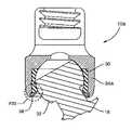
- FIGS. 1A and 1Bare perspective views of a pivoting head assembly according to one or more embodiments comprising a longitudinal member attached to the spine;
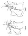
- FIGS. 2A and 2Bare perspective views of a pivoting head coupled to an anchor member according to one embodiment
- FIG. 3is a side section view of a pivoting head coupled to an anchor member and securing a longitudinal member according to one embodiment
- FIG. 4is a perspective view of an anchor member for use with a pivoting head according to one embodiment
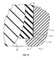
- FIGS. 5A-Care top section views of a pivoting head with an anchor member and wear member inserted therein according to different embodiments
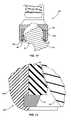
- FIG. 6is a perspective view of a wear member for use with a pivoting head according to one embodiment
- FIG. 7is a side view, including a partial section view, of an assembled anchor member and wear member for use with a pivoting head according to one embodiment
- FIG. 8is a side section view of a pivoting head with an anchor member and wear member inserted therein according to one embodiment
- FIG. 9is a side section view of an assembled pivoting head with an anchor member and wear member constrained therein according to one embodiment
- FIG. 10is a detailed section view of the bottom region of a pivoting head according to one embodiment
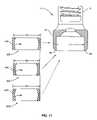
- FIG. 11is a side section view of a pivoting head and various wear members that may be used with the pivoting head according to one embodiment
- FIG. 12is a side section view of an assembled pivoting head with an anchor member and wear member constrained therein according to one embodiment
- FIG. 13is a detailed section view of the bottom region of a pivoting head according to one embodiment
- FIG. 14is a detailed section view of the bottom region of a pivoting head according to one embodiment
- FIG. 15is a detailed section view of an interference snap ring that may be used with the pivoting head according to one embodiment
- FIG. 16is a perspective view of a pivoting head coupled to an anchor member according to one embodiment
- FIG. 17is a side section view of an assembled pivoting head with an anchor member and wear member constrained therein according to one embodiment
- FIG. 18is a side section view of an assembled pivoting head with an anchor member and wear member constrained therein according to one embodiment
- FIG. 19is a perspective view of a wear member for use with a pivoting head according to one embodiment
- FIG. 20is a side section view of an assembled pivoting head with an anchor member and wear member constrained therein according to one embodiment.
- FIG. 21is a side section view of an assembled pivoting head with an anchor member and wear member constrained therein according to one embodiment.
- FIGS. 1A and 1Bshow another type of longitudinal member 15 that is secured between the sacrum S and a vertebral member V (i.e., L5).
- the longitudinal member 15is a flexible member, such as a resin or polymer compound.
- Some flexible non-metallic longitudinal members 15are constructed from materials such as PEEK and UHMWPE.
- Other types of flexible longitudinal members 15may comprise braided metallic structures.
- the longitudinal member 15is rigid or semi-rigid and may be constructed from metals, including for example stainless steels, cobalt-chrome, titanium, and shape memory alloys. Further, the longitudinal member 15 may be straight, curved, or comprise one or more curved portions along its length.
- the longitudinal member 15is secured to the vertebral member V with one embodiment of a pivoting head 10 in accordance with the teachings provided herein.
- the longitudinal member 15is secured to a saddle 16 within the pivoting head 10 with a securing member 12 .
- the securing member 12 shown in FIGS. 1A and 1Bfeatures a snap-off driving member 14 .
- the driving member 14is integrally formed with the securing member 12 and allows a surgeon to drive the securing member 12 into contact with the longitudinal member 15 to achieve a certain installation torque. Above that torque, the driving member 14 will snap off, separating from the securing member 12 . In this manner, the securing member 12 may provide the desired clamping force to secure the longitudinal member 15 .
- FIG. 1Ashows a first orientation for the pivoting head 10 identified by the centerline labeled X.
- FIG. 1Bshows a second position representing a different spatial relationship between the sacrum S and the vertebra V.
- the vertebra V in FIG. 1Bexhibits some amount of angular and torsional displacement relative to the sacrum S. Consequently, the pivoting head 10 is illustrated in a second orientation identified by the centerline labeled Y.
- the pivoting head 10may provide some or all of this rotation.
- the illustrations provided in FIGS. 1A and 1Bshow the pivoting head 10 as part of a spinal implant that is coupled between a vertebral body V and a sacrum S.
- pivoting head 10may be used in constructs that are coupled to vertebral bodies V alone.
- a vertebral implantmay be construed to mean implants that are coupled to any or all portions of a spine, including the sacrum, vertebral bodies, and the skull.
- FIGS. 2A and 2Billustrate perspective views of the illustrative embodiment of the pivoting head 10 coupled to an anchor member 18 .
- a head 32 of the anchor member 18is pivotally coupled to a base portion 34 of the pivoting head 10 .
- the anchor member 18comprises threads for insertion into a vertebral member V as shown in FIGS. 1A and 1B .
- the anchor member 18is a pedicle screw.
- the exemplary saddle 16is comprised of opposed upright portions forming a U-shaped channel within which a longitudinal member 15 is placed.
- a seating surface 24forms the bottom of the U-shaped channel.
- the seating surface 24is curved to substantially match the radius of a longitudinal member 15 that is positioned within the saddle 16 .
- An aperture 26 within the seating surfaceprovides access to a driving feature used to insert the anchor member 18 into a vertebral member V.
- FIG. 2Athe pivoting head 10 is shown substantially aligned with the anchor member 18 along the centerline labeled X.
- FIG. 2Bthe anchor member 18 is shown pivoted relative to the pivoting head 10 . That is, the pivoting head 10 is shown still aligned with the centerline labeled X while the anchor member 18 is shown aligned with the centerline labeled Y.
- the pivoted displacement of the pivoting head 10 relative to the anchor member 18 achieved in FIG. 2Bis provided by an articulation mechanism that is more clearly visible in the section view provided in FIG. 3 .
- FIG. 3shows a section view of the pivoting head 10 holding a different type of longitudinal member 28 .
- the longitudinal member 28is a spinal rod.
- the spinal rod 28is secured within the saddle 16 with a securing member 12 .
- the securing member 12is an externally threaded set screw, though other types of securing members such as externally threaded caps and nuts may be used.
- an articulation mechanism 40is disposed below the saddle 16 and generally aligned with the central axis X.
- the articulation mechanism 40comprises an anchor head 32 of the anchor member 18 that is pivotally coupled to a wear member 30 within the base portion 34 of the pivoting head 10 .
- the wear member 30 and the outer surface of the anchor head 32may be constructed of a wear resistance material.
- Some suitable examplesmay include hardened metals, titanium carbide, cobalt chrome, polymers, and ceramics.
- a wear resistant layermay be coated onto the anchor head 32 and the wear member 30 .
- the wear member 30may be integrally formed into or form a part of the base portion 34 .
- the wear member 30may be bonded to the base portion 34 using a biocompatible adhesive such as PMMA or other known adhesives.
- the part of the base portion 34 in contact with the anchor head 32may be coated with a wear resistant layer.
- Coating processesthat include, for example, vapor deposition, dip coating, diffusion bonding, and electron beam welding may be used to coat the above indicated materials onto a similar or dissimilar substrate. Diffusion bonding is a solid-state joining process capable of joining a wide range of metal and ceramic combinations.
- the processmay be applied over a variety of durations, applied pressure, bonding temperature, and method of heat application.
- the bondingis typically formed in the solid phase and may be carried out in vacuum or a protective atmosphere, with heat being applied by radiant, induction, direct or indirect resistance heating.
- Electron beam weldingis a fusion welding process in which a beam of high-velocity electrons is applied to the materials being joined. The workpieces melt as the kinetic energy of the electrons is transformed into heat upon impact. Pressure is not necessarily applied, though the welding is often done in a vacuum to prevent the dispersion of the electron beam.
- the articulation mechanism 40is spatially and functionally isolated from the clamping forces that are applied between the securing member 12 , the rod 28 , and the seating surface 24 (see FIGS. 2A , 2 B). That is, since the compression forces applied by the securing member 12 are not transmitted to the articulation mechanism 40 , the anchor member 18 rotates about the central axis X under the influence of the sliding resistance provided by the various embodiments disclosed herein. In this manner, the articulation mechanism 40 is not only spatially isolated from the securing member 12 , but also physically isolated from the forces provided by the securing member 12 .
- FIG. 4shows a perspective view of the anchor head 32 of the exemplary anchor member 18 .
- the anchor head 32includes a driving feature 42 that allows a surgeon to attach the anchor member 18 to a vertebra V.
- a hex recess driving feature 42is shown.
- Other types of driving features 42may be appropriate, including for example, slotted, star, Torx, and cross-shaped features.
- the driving feature 42may be accessed through the aperture 26 shown in FIGS. 2A , 2 B, and 3 .
- the anchor head 32is substantially spherical to allow multi-axial pivoting of the anchor member 18 relative to the pivoting head 10 .
- the anchor head 32has other shapes to allow motion in fewer directions.
- a disc-shaped anchor head 32may provide motion within a desired plane.
- FIGS. 5A , 5 B, and 5 Cillustrate some of these alternative embodiments. Specifically, FIGS. 5A-5C are top section views according to the section line X-X shown in FIG. 3 .
- FIG. 5Ashows one embodiment where the anchor head 32 and wear member 30 are substantially spherical as previously described.
- FIG. 5Ashows an alternative embodiment where the anchor head 132 and wear member 130 are substantially disc-shaped. As disclosed above, this configuration may allow pivoting motion about axis B, but not other axes, including axis A.
- FIG. 5Cdepicts another embodiment that is characterized by at least two different spherical radii R 1 , R 2 . This configuration may provide a different resistance to rotation about axes A and B. A somewhat pronounced difference in radii R 1 , R 2 is shown in FIG. 5C , though in practice, a fairly small difference may produce the desired result.
- FIG. 6shows a perspective view of a wear member 30 according to one embodiment.
- the wear member 30is cylindrically shaped and includes an outer surface 44 and an inner surface 46 extending between a top surface 50 and a bottom surface 52 .
- the inner surface 46is constructed to match the shape of the anchor head 32 of the threaded anchor member 18 .
- the outer surface 44may be configured as desired to fit within the base portion 34 of the pivoting head 10 as shown in FIG. 3 .
- the outer surface 44is substantially cylindrical.
- the exemplary wear member 30also includes a gap 48 .
- the gap 48 in the present embodimentmay be used to spread open the wear member 30 by an amount sufficient to slip the wear member 30 over the anchor head 32 of the anchor member 18 .
- the wear member 30is shown installed on the anchor head 32 in FIG. 7 .
- FIG. 7also shows relevant dimensions of the wear member 30 and the anchor head 32 .
- Dimension Lrepresents a width of the anchor head 32 at its widest point. The width may comprise a diameter, a spherical diameter, or other linear dimension.
- Dimensions M and Nrespectively represent an interior width at the top 50 and bottom 52 of the wear member 30 . Notably, dimension L is larger than both M and N.
- the gap 48allows the anchor head 32 to fit within the wear member 30 as shown in FIG. 7 .
- FIG. 8shows the assembled wear member 30 and anchor member 18 inserted into the base portion 34 of the pivoting head 10 .
- the anchor member 18 and wear member 30are retained within the base portion 34 by deforming the lower lip 56 in the direction of the arrow labeled F.
- the deforming stepmay be performed using a variety of techniques, including but not limited to mechanical pressing, swaging, and orbital forming.
- Orbital forming(or orbital forging) is a cold metal forming process during which the workpiece (the base portion 34 in this case) is transformed between upper and lower dies. The process features one or the other of these dies orbiting relative to the other with a compression force applied therebetween.
- FIG. 9The fully assembled pivoting head 10 is illustrated in FIG. 9 .
- the lower lip 56 of the base portion 34is formed to constrain the wear member 30 and the anchor member 18 .
- FIG. 10shows a detail view of the lower lip 56 of the base portion 34 .
- the forming technique used to form the lower lip 56 under and around the wear member 30may be controlled to produce a pivoting head 10 with a desired, predetermined resistance to motion.
- the dashed lines labeled INT 1 and INT 2depict this ability to control the amount of interference between the parts, and hence the amount of resistance to motion. If a greater amount of resistance to motion is desired, the lower lip 56 may be deformed a greater amount as indicated by the dashed line labeled INT 2 . A lesser amount of deformation indicated by the dashed line INT 1 may produce less resistance to motion.
- the lower lip 56is formed to produce a very large resistance to motion such that the pivoting head 10 is, for all practical purposes, fixed.
- the lower lip 56is formed to merely place the relevant parts (base portion 34 , wear member 30 , and anchor head 32 ) in contact with one another or in close proximity to one another.
- the pivoting head 10is free to rotate with very little or no resistance to motion. At points between these extremes (indicated by dashed line INT 1 ), a desired amount of interference may produce a desirable resistance to motion.
- the resistance to motionmay be measured in standard torque units, such as inch-ounces or other units of measure.
- the measurable resistance to motionmay be marked on the exterior of the pivoting head 10 to provide surgeons an indication of the relative flexibility of the pivoting head 10 .
- This markingmay be provided as an alphanumeric indication as represented by the letter T in FIGS. 2A and 2B .
- the markingmay be stamped, whether by ink or metal deformation, engraved, or otherwise displayed on the pivoting head 10 .
- FIG. 11shows a pivoting head 10 , including a base portion 34 that is defined in part by a dimension D 1 .
- This dimension D 1corresponds approximately to the outer dimension of the wear members 30 b , 30 c , and 30 d that are also shown in FIG. 10 .
- each wear member 30 b - dhas a slightly different outer dimension D 2 -D 4 .
- wear member 30 bis characterized by the largest outer dimension D 2 .
- Wear member 30 cis characterized by the smallest outer diameter D 3 and wear member 30 d is somewhere between, with an outer diameter D 4 . It is assumed for the sake of this discussion, that the inner surface 46 is the same for all three wear members 30 b - d . In an alternative embodiment, the inner surface 46 may be constructed with different sizes to create different amounts of interference with the anchor head 32 of the anchor member 18 . In an alternative embodiment, both the inner 46 and outer 44 surfaces may vary between wear members 30 . That is, different wear members 30 may have different thicknesses. In an alternative embodiment, the resistance to pivoting motion of the head 32 may be provided by materials having different coefficients of friction.
- wear member 30 cwill result in the least amount of interference when used in the pivoting head 10 .
- wear member 30 bwill result in the greatest amount of interference when used in the pivoting head 10 .
- a measurable resistance to motion of the pivoting head 10can be determined once the parts are assembled. As indicated above, this measured resistance to motion may be marked on the exterior of the pivoting head 10 to provide surgeons an indication of the relative flexibility of the pivoting head 10 .
- FIG. 12shows an alternative embodiment of the pivoting head 10 a .
- the section viewshows an alternative technique for retaining the wear member 30 and anchor member 18 within the base portion 34 a .
- a snap ring 58is inserted into the bottom of the base portion 34 a beneath the wear member 30 .
- the snap ring 58may effectively retain the wear member 30 and anchor member 18 within the pivoting head 10 a .
- a detailed view of the area around the snap ring 58is shown in FIG. 13 .
- the snap ring 58acts as a barrier to prevent the wear member 30 from escaping but does not contribute to any interference between the other parts ( 30 , 32 , 34 ).
- a snap ring 158may contribute to the overall resistance to motion of the pivoting head 10 b .
- the snap ring 158is configured to fit within the interior of the base portion 34 b .
- the interior portion of the snap ring 158is modified slightly to create an interference with the wear member 30 e .
- the wear member 30 eis slightly modified to include a rounded lower outside corner 60 to facilitate insertion of the snap ring 158 .
- a detailed view of a cross section of the snap ring 158is shown in FIG. 15 .
- the exemplary snap ring 158comprises a bottom surface 64 , a top surface 66 , and an outer surface 62 , each of which are configured to fit within the body portion 34 b of the pivoting head 10 b .
- a retaining surface 68further acts to keep the wear member 30 e within the pivoting head 10 b .
- This snap ring 158also includes an interference surface 70 that contacts the wear member 30 e to create a force G (shown in FIG. 14 ) that compresses the wear member 158 towards the anchor head 32 .
- the compression force Gcreates an interference that resists pivoting motion of the anchor head 32 relative to the wear member 30 e .
- Snap rings 158 including different interference surfaces 72 , 74may be selected to create more or less interference as desired.
- a measurable resistance to motion of the pivoting head 10 bcan be determined. As indicated above, this measured resistance to motion may be marked on the exterior of the pivoting head 10 b to provide surgeons an indication of the relative flexibility of the pivoting head 10 b.
- FIGS. 16 and 17illustrate an alternative embodiment of the pivoting head 10 c .
- the resistance to motionmay be set intra-operatively.
- the base portion 34 c of the pivoting head 10 cincludes one or more adjustment members 76 that allow a surgeon to adjust the amount of interference between the wear member 30 and the anchor head 32 . Further, a surgeon may be able to adjust this amount of interference differently about different axes depending upon how many adjustment members 76 are provided. In the embodiments illustrated, there are four total adjustment members 76 , disposed approximately 90 degrees apart from one another. More or fewer adjustment members 76 may be provided. Also, in one embodiment, one of the adjustment members 76 is substantially aligned with the orientation in which a longitudinal member 15 lies.
- one adjustment member 76is substantially parallel to the seating surface 24 .
- an adjustment member 76is substantially transverse to this seating surface.
- the adjustment members 76are setscrews that may be screwed in to create a compressive force H that is shown in FIG. 17 .
- the adjustment member 76may be a pin.
- the compressive force Hmay create an increased amount of interference that also creates more resistance to motion.
- FIG. 18shows an alternative embodiment of the pivoting head 10 d that includes a threaded region 78 disposed towards a bottom of the base portion 34 d .
- An adjustment member 80 having substantially matching threads 84is threaded onto the threads 78 on the base portion 34 d and rotated until the desired resistance to motion is obtained. This procedure may be performed intra-operatively.
- the threads 78 , 84are tapered threads to create an increasing amount of inward compression J and corresponding interference.
- a lower opening 82 of the adjustment member 80is smaller than a width of the threaded portion 78 of the base portion 34 d . Consequently, the more the adjustment member 80 is threaded onto the base portion 34 d , the base portion 34 d is compressed an increasing amount.
- FIG. 19shows an alternative embodiment of the wear member 30 a that may be used in one or more embodiments disclosed herein.
- the wear member 30 aalso includes a series of gaps 48 a as with the previous embodiment shown in FIG. 6 . However, gaps 48 a do not extend from the bottom surface 52 a to the top surface 50 a .
- the top surface 50 a of the wear member 30 ais substantially continuous.
- the wear member 30 acomprises four gaps 48 a separated by approximately 90 degrees. In other embodiments, more or fewer numbers of gaps 48 a are used. Since the gaps 48 a originate at the bottom surface 52 a of the wear member 30 a , inward deflection of the wear member 30 a , particularly near the bottom surface 52 a , is possible. This feature may be appropriate for one or more embodiments where inward deflection of the wear member 30 a is used to create a desired resistance to motion.
- Embodiments described abovehave contemplated an anchor member 18 that comprises threads for insertion into a vertebral member V.
- the pivoting head 10may be incorporated on other types of bone screws.
- different types of screwsmay be used to attach longitudinal members 15 to the sacrum S or to other parts of a vertebral member V. These include, for example, anterior and lateral portions of a vertebral body.
- the pivoting head 10may be implemented on other types of anchoring members.
- FIG. 20shows a pivoting head 10 incorporated onto a hook-type anchor member 118 .
- the pivoting head 10is incorporated onto another type of threaded anchor member 218 that is inserted into a plate 220 instead of a bony member.
- a pivoting head 10having a substantially U-shaped recess in which to hold a longitudinal member 15 .
- a pivoting head 10having a substantially U-shaped recess in which to hold a longitudinal member 15 .
- articulation mechanism 40described herein.
- alternative embodiments of the pivoting headmay have circular apertures, C-shaped clamps, and multi-piece clamps as are known to secure a longitudinal member.
- the present embodimentsare, therefore, to be considered in all respects as illustrative and not restrictive, and all changes coming within the meaning and equivalency range of the appended claims are intended to be embraced therein.
Landscapes
- Health & Medical Sciences (AREA)
- Orthopedic Medicine & Surgery (AREA)
- Life Sciences & Earth Sciences (AREA)
- Neurology (AREA)
- Surgery (AREA)
- Heart & Thoracic Surgery (AREA)
- Engineering & Computer Science (AREA)
- Biomedical Technology (AREA)
- Nuclear Medicine, Radiotherapy & Molecular Imaging (AREA)
- Medical Informatics (AREA)
- Molecular Biology (AREA)
- Animal Behavior & Ethology (AREA)
- General Health & Medical Sciences (AREA)
- Public Health (AREA)
- Veterinary Medicine (AREA)
- Surgical Instruments (AREA)
- Prostheses (AREA)
Abstract
Description
Claims (21)
Priority Applications (9)
| Application Number | Priority Date | Filing Date | Title |
|---|---|---|---|
| US11/341,188US7722652B2 (en) | 2006-01-27 | 2006-01-27 | Pivoting joints for spinal implants including designed resistance to motion and methods of use |
| US11/493,447US7833252B2 (en) | 2006-01-27 | 2006-07-26 | Pivoting joints for spinal implants including designed resistance to motion and methods of use |
| PCT/US2007/061131WO2007087628A1 (en) | 2006-01-27 | 2007-01-26 | Pivoting joints for spinal implants including designed resistance to motion and methods of use |
| AU2007207996AAU2007207996A1 (en) | 2006-01-27 | 2007-01-26 | Pivoting joints for spinal implants including designed resistance to motion and methods of use |
| EP07710326AEP1981421A1 (en) | 2006-01-27 | 2007-01-26 | Pivoting joints for spinal implants including designed resistance to motion and methods of use |
| JP2008552593AJP2009524505A (en) | 2006-01-27 | 2007-01-26 | Pivot joints for spinal implants with designed motion resistance |
| US12/038,572US8057519B2 (en) | 2006-01-27 | 2008-02-27 | Multi-axial screw assembly |
| PCT/US2009/034959WO2009108618A1 (en) | 2006-01-27 | 2009-02-24 | Multi-axial screw assembly |
| US12/762,869US8298270B2 (en) | 2006-01-27 | 2010-04-19 | Pivoting joints for spinal implants including designed resistance to motion and methods of use |
Applications Claiming Priority (1)
| Application Number | Priority Date | Filing Date | Title |
|---|---|---|---|
| US11/341,188US7722652B2 (en) | 2006-01-27 | 2006-01-27 | Pivoting joints for spinal implants including designed resistance to motion and methods of use |
Related Child Applications (2)
| Application Number | Title | Priority Date | Filing Date |
|---|---|---|---|
| US11/493,447Continuation-In-PartUS7833252B2 (en) | 2006-01-27 | 2006-07-26 | Pivoting joints for spinal implants including designed resistance to motion and methods of use |
| US12/762,869DivisionUS8298270B2 (en) | 2006-01-27 | 2010-04-19 | Pivoting joints for spinal implants including designed resistance to motion and methods of use |
Publications (2)
| Publication Number | Publication Date |
|---|---|
| US20070191835A1 US20070191835A1 (en) | 2007-08-16 |
| US7722652B2true US7722652B2 (en) | 2010-05-25 |
Family
ID=37969723
Family Applications (2)
| Application Number | Title | Priority Date | Filing Date |
|---|---|---|---|
| US11/341,188Active2027-12-15US7722652B2 (en) | 2006-01-27 | 2006-01-27 | Pivoting joints for spinal implants including designed resistance to motion and methods of use |
| US12/762,869Active2026-09-04US8298270B2 (en) | 2006-01-27 | 2010-04-19 | Pivoting joints for spinal implants including designed resistance to motion and methods of use |
Family Applications After (1)
| Application Number | Title | Priority Date | Filing Date |
|---|---|---|---|
| US12/762,869Active2026-09-04US8298270B2 (en) | 2006-01-27 | 2010-04-19 | Pivoting joints for spinal implants including designed resistance to motion and methods of use |
Country Status (5)
| Country | Link |
|---|---|
| US (2) | US7722652B2 (en) |
| EP (1) | EP1981421A1 (en) |
| JP (1) | JP2009524505A (en) |
| AU (1) | AU2007207996A1 (en) |
| WO (1) | WO2007087628A1 (en) |
Cited By (33)
| Publication number | Priority date | Publication date | Assignee | Title |
|---|---|---|---|---|
| US20050203516A1 (en)* | 2004-03-03 | 2005-09-15 | Biedermann Motech Gmbh | Anchoring element and stabilization device for the dynamic stabilization of vertebrae or bones using such anchoring elements |
| US20100198269A1 (en)* | 2004-10-05 | 2010-08-05 | Warsaw Orthopedic, Inc. | Spinal Implants with Multi-Axial Anchor Assembly and Methods |
| US8377067B2 (en) | 2004-02-27 | 2013-02-19 | Roger P. Jackson | Orthopedic implant rod reduction tool set and method |
| US8394133B2 (en) | 2004-02-27 | 2013-03-12 | Roger P. Jackson | Dynamic fixation assemblies with inner core and outer coil-like member |
| US20130096622A1 (en)* | 2011-08-18 | 2013-04-18 | Timo Biedermann | Polyaxial bone anchoring device |
| US8444681B2 (en) | 2009-06-15 | 2013-05-21 | Roger P. Jackson | Polyaxial bone anchor with pop-on shank, friction fit retainer and winged insert |
| US8556938B2 (en) | 2009-06-15 | 2013-10-15 | Roger P. Jackson | Polyaxial bone anchor with non-pivotable retainer and pop-on shank, some with friction fit |
| US8814911B2 (en) | 2003-06-18 | 2014-08-26 | Roger P. Jackson | Polyaxial bone screw with cam connection and lock and release insert |
| US8894657B2 (en) | 2004-02-27 | 2014-11-25 | Roger P. Jackson | Tool system for dynamic spinal implants |
| US8911479B2 (en) | 2012-01-10 | 2014-12-16 | Roger P. Jackson | Multi-start closures for open implants |
| US8998959B2 (en) | 2009-06-15 | 2015-04-07 | Roger P Jackson | Polyaxial bone anchors with pop-on shank, fully constrained friction fit retainer and lock and release insert |
| US9034022B2 (en) | 2012-08-09 | 2015-05-19 | Spinecraft, LLC | Locking force augmentation features for surgical screw assembly |
| US9050139B2 (en) | 2004-02-27 | 2015-06-09 | Roger P. Jackson | Orthopedic implant rod reduction tool set and method |
| US9168069B2 (en) | 2009-06-15 | 2015-10-27 | Roger P. Jackson | Polyaxial bone anchor with pop-on shank and winged insert with lower skirt for engaging a friction fit retainer |
| US9179957B2 (en) | 2012-08-09 | 2015-11-10 | Spinecraft, LLC | Systems, assemblies and methods for spinal derotation |
| US9216039B2 (en) | 2004-02-27 | 2015-12-22 | Roger P. Jackson | Dynamic spinal stabilization assemblies, tool set and method |
| US20160015429A1 (en)* | 2014-07-18 | 2016-01-21 | Warsaw Orthopedic, Inc. | Bone fastener and methods of use |
| US9393047B2 (en) | 2009-06-15 | 2016-07-19 | Roger P. Jackson | Polyaxial bone anchor with pop-on shank and friction fit retainer with low profile edge lock |
| US9451992B2 (en)* | 2010-12-01 | 2016-09-27 | Facet-Link Inc. | Variable angle bone screw fixation arrangement |
| US9480517B2 (en) | 2009-06-15 | 2016-11-01 | Roger P. Jackson | Polyaxial bone anchor with pop-on shank, shank, friction fit retainer, winged insert and low profile edge lock |
| US20160331413A1 (en)* | 2014-06-13 | 2016-11-17 | Orthopediatrics Corp. | Bottom loaded pedicle screw |
| US9629669B2 (en) | 2004-11-23 | 2017-04-25 | Roger P. Jackson | Spinal fixation tool set and method |
| US9743957B2 (en) | 2004-11-10 | 2017-08-29 | Roger P. Jackson | Polyaxial bone screw with shank articulation pressure insert and method |
| US9833263B2 (en)* | 2015-04-13 | 2017-12-05 | Medos International Sarl | Bone anchor assemblies with orientation indicator |
| US9907574B2 (en) | 2008-08-01 | 2018-03-06 | Roger P. Jackson | Polyaxial bone anchors with pop-on shank, friction fit fully restrained retainer, insert and tool receiving features |
| US9980753B2 (en) | 2009-06-15 | 2018-05-29 | Roger P Jackson | pivotal anchor with snap-in-place insert having rotation blocking extensions |
| US10039578B2 (en) | 2003-12-16 | 2018-08-07 | DePuy Synthes Products, Inc. | Methods and devices for minimally invasive spinal fixation element placement |
| US10039577B2 (en) | 2004-11-23 | 2018-08-07 | Roger P Jackson | Bone anchor receiver with horizontal radiused tool attachment structures and parallel planar outer surfaces |
| US10194951B2 (en) | 2005-05-10 | 2019-02-05 | Roger P. Jackson | Polyaxial bone anchor with compound articulation and pop-on shank |
| US10299839B2 (en) | 2003-12-16 | 2019-05-28 | Medos International Sárl | Percutaneous access devices and bone anchor assemblies |
| US10363070B2 (en) | 2009-06-15 | 2019-07-30 | Roger P. Jackson | Pivotal bone anchor assemblies with pressure inserts and snap on articulating retainers |
| US11419642B2 (en) | 2003-12-16 | 2022-08-23 | Medos International Sarl | Percutaneous access devices and bone anchor assemblies |
| US12383311B2 (en) | 2010-05-14 | 2025-08-12 | Roger P. Jackson | Pivotal bone anchor assembly and method for use thereof |
Families Citing this family (66)
| Publication number | Priority date | Publication date | Assignee | Title |
|---|---|---|---|---|
| US7833250B2 (en) | 2004-11-10 | 2010-11-16 | Jackson Roger P | Polyaxial bone screw with helically wound capture connection |
| US8876868B2 (en) | 2002-09-06 | 2014-11-04 | Roger P. Jackson | Helical guide and advancement flange with radially loaded lip |
| US7377923B2 (en) | 2003-05-22 | 2008-05-27 | Alphatec Spine, Inc. | Variable angle spinal screw assembly |
| US8926670B2 (en) | 2003-06-18 | 2015-01-06 | Roger P. Jackson | Polyaxial bone screw assembly |
| US7967850B2 (en) | 2003-06-18 | 2011-06-28 | Jackson Roger P | Polyaxial bone anchor with helical capture connection, insert and dual locking assembly |
| US8366753B2 (en) | 2003-06-18 | 2013-02-05 | Jackson Roger P | Polyaxial bone screw assembly with fixed retaining structure |
| US11241261B2 (en) | 2005-09-30 | 2022-02-08 | Roger P Jackson | Apparatus and method for soft spinal stabilization using a tensionable cord and releasable end structure |
| US8926672B2 (en) | 2004-11-10 | 2015-01-06 | Roger P. Jackson | Splay control closure for open bone anchor |
| WO2006057837A1 (en) | 2004-11-23 | 2006-06-01 | Jackson Roger P | Spinal fixation tool attachment structure |
| US7901437B2 (en) | 2007-01-26 | 2011-03-08 | Jackson Roger P | Dynamic stabilization member with molded connection |
| US8075599B2 (en)* | 2005-10-18 | 2011-12-13 | Warsaw Orthopedic, Inc. | Adjustable bone anchor assembly |
| US20080015576A1 (en)* | 2006-04-28 | 2008-01-17 | Whipple Dale E | Large diameter bone anchor assembly |
| US20080015597A1 (en)* | 2006-04-28 | 2008-01-17 | Whipple Dale E | Large diameter bone anchor assembly |
| US8133262B2 (en)* | 2006-04-28 | 2012-03-13 | Depuy Spine, Inc. | Large diameter bone anchor assembly |
| US8361129B2 (en) | 2006-04-28 | 2013-01-29 | Depuy Spine, Inc. | Large diameter bone anchor assembly |
| US8636783B2 (en)* | 2006-12-29 | 2014-01-28 | Zimmer Spine, Inc. | Spinal stabilization systems and methods |
| US8007522B2 (en) | 2008-02-04 | 2011-08-30 | Depuy Spine, Inc. | Methods for correction of spinal deformities |
| US8088163B1 (en) | 2008-02-06 | 2012-01-03 | Kleiner Jeffrey B | Tools and methods for spinal fusion |
| US20210378834A1 (en) | 2008-05-22 | 2021-12-09 | Spinal Surgical Strategies, Inc., A Nevada Corporation D/B/A Kleiner Device Labs | Spinal fusion cage system with inserter |
| USD853560S1 (en) | 2008-10-09 | 2019-07-09 | Nuvasive, Inc. | Spinal implant insertion device |
| US9717403B2 (en) | 2008-12-05 | 2017-08-01 | Jeffrey B. Kleiner | Method and apparatus for performing retro peritoneal dissection |
| US8864654B2 (en) | 2010-04-20 | 2014-10-21 | Jeffrey B. Kleiner | Method and apparatus for performing retro peritoneal dissection |
| US8366748B2 (en) | 2008-12-05 | 2013-02-05 | Kleiner Jeffrey | Apparatus and method of spinal implant and fusion |
| USD656610S1 (en) | 2009-02-06 | 2012-03-27 | Kleiner Jeffrey B | Spinal distraction instrument |
| US9247943B1 (en) | 2009-02-06 | 2016-02-02 | Kleiner Intellectual Property, Llc | Devices and methods for preparing an intervertebral workspace |
| WO2010124230A1 (en) | 2009-04-23 | 2010-10-28 | University Of Massachusetts | Bone fixture assembly |
| US9566098B2 (en) | 2009-04-23 | 2017-02-14 | University Of Massachusetts | Bone fixture assembly |
| US11229457B2 (en) | 2009-06-15 | 2022-01-25 | Roger P. Jackson | Pivotal bone anchor assembly with insert tool deployment |
| US9668771B2 (en) | 2009-06-15 | 2017-06-06 | Roger P Jackson | Soft stabilization assemblies with off-set connector |
| US20170238984A1 (en) | 2009-09-18 | 2017-08-24 | Spinal Surgical Strategies, Llc | Bone graft delivery device with positioning handle |
| US9629729B2 (en) | 2009-09-18 | 2017-04-25 | Spinal Surgical Strategies, Llc | Biological delivery system with adaptable fusion cage interface |
| US8906028B2 (en) | 2009-09-18 | 2014-12-09 | Spinal Surgical Strategies, Llc | Bone graft delivery device and method of using the same |
| USD750249S1 (en) | 2014-10-20 | 2016-02-23 | Spinal Surgical Strategies, Llc | Expandable fusion cage |
| US9186193B2 (en) | 2009-09-18 | 2015-11-17 | Spinal Surgical Strategies, Llc | Fusion cage with combined biological delivery system |
| US10245159B1 (en) | 2009-09-18 | 2019-04-02 | Spinal Surgical Strategies, Llc | Bone graft delivery system and method for using same |
| US8685031B2 (en) | 2009-09-18 | 2014-04-01 | Spinal Surgical Strategies, Llc | Bone graft delivery system |
| USD723682S1 (en) | 2013-05-03 | 2015-03-03 | Spinal Surgical Strategies, Llc | Bone graft delivery tool |
| US9060877B2 (en) | 2009-09-18 | 2015-06-23 | Spinal Surgical Strategies, Llc | Fusion cage with combined biological delivery system |
| US10973656B2 (en) | 2009-09-18 | 2021-04-13 | Spinal Surgical Strategies, Inc. | Bone graft delivery system and method for using same |
| US9173694B2 (en) | 2009-09-18 | 2015-11-03 | Spinal Surgical Strategies, Llc | Fusion cage with combined biological delivery system |
| US8361123B2 (en) | 2009-10-16 | 2013-01-29 | Depuy Spine, Inc. | Bone anchor assemblies and methods of manufacturing and use thereof |
| WO2011077511A1 (en)* | 2009-12-22 | 2011-06-30 | 株式会社ロバート・リード商会 | Spine fixing device, embedding device, embedding member fixing device, and spine fixing system |
| FR2963227B1 (en)* | 2010-07-29 | 2013-06-14 | Clariance | IMPROVEMENT FOR FACETARY ARTHROPLASTY DEVICE |
| US9993269B2 (en) | 2011-07-15 | 2018-06-12 | Globus Medical, Inc. | Orthopedic fixation devices and methods of installation thereof |
| US11172961B2 (en) | 2011-07-15 | 2021-11-16 | Globus Medical Inc. | Orthopedic fixation devices and methods of installation thereof |
| US11103286B2 (en) | 2011-07-15 | 2021-08-31 | Globus Medical, Inc. | Orthopedic fixation devices and methods of installation thereof |
| US9999447B2 (en) | 2011-07-15 | 2018-06-19 | Globus Medical, Inc. | Orthopedic fixation devices and methods of installation thereof |
| US9782204B2 (en) | 2012-09-28 | 2017-10-10 | Medos International Sarl | Bone anchor assemblies |
| US8911478B2 (en) | 2012-11-21 | 2014-12-16 | Roger P. Jackson | Splay control closure for open bone anchor |
| US10058354B2 (en) | 2013-01-28 | 2018-08-28 | Roger P. Jackson | Pivotal bone anchor assembly with frictional shank head seating surfaces |
| US8852239B2 (en) | 2013-02-15 | 2014-10-07 | Roger P Jackson | Sagittal angle screw with integral shank and receiver |
| US10342582B2 (en) | 2013-03-14 | 2019-07-09 | DePuy Synthes Products, Inc. | Bone anchor assemblies and methods with improved locking |
| US9724145B2 (en) | 2013-03-14 | 2017-08-08 | Medos International Sarl | Bone anchor assemblies with multiple component bottom loading bone anchors |
| US9259247B2 (en) | 2013-03-14 | 2016-02-16 | Medos International Sarl | Locking compression members for use with bone anchor assemblies and methods |
| US20140277153A1 (en) | 2013-03-14 | 2014-09-18 | DePuy Synthes Products, LLC | Bone Anchor Assemblies and Methods With Improved Locking |
| US9775660B2 (en) | 2013-03-14 | 2017-10-03 | DePuy Synthes Products, Inc. | Bottom-loading bone anchor assemblies and methods |
| US9566092B2 (en) | 2013-10-29 | 2017-02-14 | Roger P. Jackson | Cervical bone anchor with collet retainer and outer locking sleeve |
| US9717533B2 (en) | 2013-12-12 | 2017-08-01 | Roger P. Jackson | Bone anchor closure pivot-splay control flange form guide and advancement structure |
| US9451993B2 (en) | 2014-01-09 | 2016-09-27 | Roger P. Jackson | Bi-radial pop-on cervical bone anchor |
| US10064658B2 (en) | 2014-06-04 | 2018-09-04 | Roger P. Jackson | Polyaxial bone anchor with insert guides |
| US9597119B2 (en) | 2014-06-04 | 2017-03-21 | Roger P. Jackson | Polyaxial bone anchor with polymer sleeve |
| USD797290S1 (en) | 2015-10-19 | 2017-09-12 | Spinal Surgical Strategies, Llc | Bone graft delivery tool |
| EP3351194B1 (en)* | 2017-01-19 | 2022-10-12 | Globus Medical, Inc. | Orthopedic fixation devices |
| EP3536271B1 (en) | 2018-03-06 | 2022-05-04 | Biedermann Technologies GmbH & Co. KG | Polyaxial bone anchoring device and system of an instrument and a polyaxial bone anchoring device |
| WO2022184797A1 (en) | 2021-03-05 | 2022-09-09 | Medos International Sarl | Selectively locking polyaxial screw |
| US11439437B1 (en) | 2021-06-09 | 2022-09-13 | Medos International Sarl | Bottom loading bone anchor assemblies with drag retaining ring and related methods |
Citations (150)
| Publication number | Priority date | Publication date | Assignee | Title |
|---|---|---|---|---|
| US4304011A (en) | 1980-08-25 | 1981-12-08 | Whelan Iii Edward J | Semi-constrained metacarpophalangeal prosthesis |
| US4946458A (en) | 1986-04-25 | 1990-08-07 | Harms Juergen | Pedicle screw |
| US5084048A (en) | 1989-07-12 | 1992-01-28 | Sulzer Brothers Limited | Implant for vertebrae with spinal stabilizer |
| US5190543A (en) | 1990-11-26 | 1993-03-02 | Synthes (U.S.A.) | Anchoring device |
| US5443467A (en) | 1993-03-10 | 1995-08-22 | Biedermann Motech Gmbh | Bone screw |
| US5474555A (en) | 1990-04-26 | 1995-12-12 | Cross Medical Products | Spinal implant system |
| US5480041A (en) | 1994-06-27 | 1996-01-02 | Turner; Eugene M. | Trailer-mounted crane |
| US5480401A (en) | 1993-02-17 | 1996-01-02 | Psi | Extra-discal inter-vertebral prosthesis for controlling the variations of the inter-vertebral distance by means of a double damper |
| US5549608A (en) | 1995-07-13 | 1996-08-27 | Fastenetix, L.L.C. | Advanced polyaxial locking screw and coupling element device for use with rod fixation apparatus |
| US5591166A (en) | 1995-03-27 | 1997-01-07 | Smith & Nephew Richards, Inc. | Multi angle bone bolt |
| US5669911A (en) | 1995-04-13 | 1997-09-23 | Fastenetix, L.L.C. | Polyaxial pedicle screw |
| US5733285A (en) | 1995-07-13 | 1998-03-31 | Fastenetix, Llc | Polyaxial locking mechanism |
| US5797911A (en) | 1996-09-24 | 1998-08-25 | Sdgi Holdings, Inc. | Multi-axial bone screw assembly |
| US5810819A (en) | 1997-05-15 | 1998-09-22 | Spinal Concepts, Inc. | Polyaxial pedicle screw having a compression locking rod gripping mechanism |
| US5863293A (en) | 1996-10-18 | 1999-01-26 | Spinal Innovations | Spinal implant fixation assembly |
| US5882350A (en) | 1995-04-13 | 1999-03-16 | Fastenetix, Llc | Polyaxial pedicle screw having a threaded and tapered compression locking mechanism |
| US5885286A (en) | 1996-09-24 | 1999-03-23 | Sdgi Holdings, Inc. | Multi-axial bone screw assembly |
| US5888204A (en) | 1996-04-15 | 1999-03-30 | Fastenetix, Llc | Acetabular cup having capped polyaxial locking screws |
| US5891145A (en)* | 1997-07-14 | 1999-04-06 | Sdgi Holdings, Inc. | Multi-axial screw |
| US5954725A (en) | 1996-11-07 | 1999-09-21 | Sdgi Holdings, Inc. | Multi-angle bone screw assembly using shape memory technology |
| US5989254A (en) | 1997-05-20 | 1999-11-23 | Katz; Akiva Raphael | Pedicle screw assembly |
| US6063090A (en)* | 1996-12-12 | 2000-05-16 | Synthes (U.S.A.) | Device for connecting a longitudinal support to a pedicle screw |
| US6074391A (en) | 1997-06-16 | 2000-06-13 | Howmedica Gmbh | Receiving part for a retaining component of a vertebral column implant |
| US6146421A (en) | 1997-08-04 | 2000-11-14 | Gordon, Maya, Roberts And Thomas, Number 1, Llc | Multiple axis intervertebral prosthesis |
| US6248105B1 (en)* | 1997-05-17 | 2001-06-19 | Synthes (U.S.A.) | Device for connecting a longitudinal support with a pedicle screw |
| US6258089B1 (en) | 1998-05-19 | 2001-07-10 | Alphatec Manufacturing, Inc. | Anterior cervical plate and fixation system |
| US6261287B1 (en) | 1992-03-02 | 2001-07-17 | Stryker Trauma Gmbh | Apparatus for bracing vertebrae |
| US6273888B1 (en) | 1999-05-28 | 2001-08-14 | Sdgi Holdings, Inc. | Device and method for selectively preventing the locking of a shape-memory alloy coupling system |
| US6280442B1 (en)* | 1999-09-01 | 2001-08-28 | Sdgi Holdings, Inc. | Multi-axial bone screw assembly |
| US6290703B1 (en) | 1996-05-13 | 2001-09-18 | Stryker France S.A. | Device for fixing the sacral bone to adjacent vertebrae during osteosynthesis of the backbone |
| US6368321B1 (en)* | 2000-12-04 | 2002-04-09 | Roger P. Jackson | Lockable swivel head bone screw |
| US6440137B1 (en) | 2000-04-18 | 2002-08-27 | Andres A. Horvath | Medical fastener cap system |
| US20020138076A1 (en) | 2000-12-27 | 2002-09-26 | Biederman Motech Gmbh | Screw |
| US20030045879A1 (en) | 2001-07-04 | 2003-03-06 | Richard Minfelde | Connector for a spinal fixation member |
| US6554834B1 (en) | 1999-10-07 | 2003-04-29 | Stryker Spine | Slotted head pedicle screw assembly |
| US6605090B1 (en) | 2000-10-25 | 2003-08-12 | Sdgi Holdings, Inc. | Non-metallic implant devices and intra-operative methods for assembly and fixation |
| US6626908B2 (en) | 2000-07-22 | 2003-09-30 | Corin Spinal Systems Limited | Pedicle attachment assembly |
| US20040049272A1 (en) | 1999-10-22 | 2004-03-11 | Archus Orthopedics, Inc. | Facet arthroplasty devices and methods |
| US6716214B1 (en) | 2003-06-18 | 2004-04-06 | Roger P. Jackson | Polyaxial bone screw with spline capture connection |
| US6733502B2 (en) | 2002-05-15 | 2004-05-11 | Cross Medical Products, Inc. | Variable locking spinal screw having a knurled collar |
| US6736820B2 (en) | 2000-11-10 | 2004-05-18 | Biedermann Motech Gmbh | Bone screw |
| US20040102781A1 (en) | 2002-11-25 | 2004-05-27 | U & I Corporation | Bone fixation apparatus, method and tool for assembling the same |
| US6749361B2 (en) | 1997-10-06 | 2004-06-15 | Werner Hermann | Shackle element for clamping a fixation rod, a method for making a shackle element, a hook with a shackle element and a rode connector with a shackle element |
| US20040176766A1 (en) | 2002-02-13 | 2004-09-09 | Shluzas Alan E. | Apparatus for connecting a longitudinal member to a bone portion |
| US20040181224A1 (en) | 2003-03-11 | 2004-09-16 | Biedermann Motech Gmbh | Anchoring element for use in spine or bone surgery, methods for use and production thereof |
| US6793658B2 (en) | 2001-04-06 | 2004-09-21 | Society De Fabrication De Material Orthopedique, S.A. | Anterior plating system and method |
| US20040186473A1 (en) | 2003-03-21 | 2004-09-23 | Cournoyer John R. | Spinal fixation devices of improved strength and rigidity |
| US20040225289A1 (en) | 2003-05-07 | 2004-11-11 | Biedermann Motech Gmbh | Dynamic anchoring device and dynamic stabilization device for bones, in particular for vertebrae, with such an anchoring device |
| US20040249380A1 (en) | 2001-01-12 | 2004-12-09 | Craig Glascott | Polyaxial screw with improved locking |
| US20040260284A1 (en) | 2003-06-23 | 2004-12-23 | Matthew Parker | Anti-splay pedicle screw |
| US20040267264A1 (en) | 2003-06-27 | 2004-12-30 | Konieczynski David D. | Polyaxial bone screw |
| US20050033431A1 (en) | 2003-08-05 | 2005-02-10 | Charles Gordon | Artificial functional spinal unit assemblies |
| US20050033439A1 (en) | 2003-08-05 | 2005-02-10 | Charles Gordon | Artificial functional spinal unit assemblies |
| US20050033432A1 (en) | 2003-08-05 | 2005-02-10 | Charles Gordon | Artificial spinal unit assemblies |
| WO2005016194A2 (en) | 2003-08-05 | 2005-02-24 | Flexuspine, Inc. | Artificial spinal unit assemblies |
| US20050049588A1 (en) | 2003-08-28 | 2005-03-03 | Jackson Roger P. | Polyaxial bone screw with split retainer ring |
| US20050049589A1 (en) | 2003-08-28 | 2005-03-03 | Jackson Roger P. | Polyaxial bone screw apparatus |
| US6918911B2 (en) | 2002-03-27 | 2005-07-19 | Biedermann Motech Gmbh | Bone anchoring device for stabilizing bone segments and seat part of a bone anchoring device |
| US20050187548A1 (en) | 2004-01-13 | 2005-08-25 | Butler Michael S. | Pedicle screw constructs for spine fixation systems |
| US20050192571A1 (en) | 2004-02-27 | 2005-09-01 | Custom Spine, Inc. | Polyaxial pedicle screw assembly |
| EP1570794A1 (en) | 2004-03-04 | 2005-09-07 | U & I Corporation | Bone fixation apparatus, method and tool for assembling the same |
| US20050203516A1 (en) | 2004-03-03 | 2005-09-15 | Biedermann Motech Gmbh | Anchoring element and stabilization device for the dynamic stabilization of vertebrae or bones using such anchoring elements |
| US6945972B2 (en) | 2000-08-24 | 2005-09-20 | Synthes | Apparatus for connecting a bone fastener to a longitudinal rod |
| US20050209698A1 (en) | 2003-08-05 | 2005-09-22 | Gordon Charles R | Expandable intervertebral implant |
| US20050228385A1 (en) | 2004-04-08 | 2005-10-13 | Globus Medical Inc. | Polyaxial screw |
| US6964666B2 (en) | 2003-04-09 | 2005-11-15 | Jackson Roger P | Polyaxial bone screw locking mechanism |
| US6964662B2 (en) | 2002-04-09 | 2005-11-15 | Pentax Corporation | Endoscopic forceps instrument |
| US20050267472A1 (en) | 2002-03-27 | 2005-12-01 | Biedermann Motech Gmbh | Bone anchoring device for stabilising bone segments and seat part of a bone anchoring device |
| US6974460B2 (en) | 2001-09-14 | 2005-12-13 | Stryker Spine | Biased angulation bone fixation assembly |
| US6974461B1 (en) | 1999-09-14 | 2005-12-13 | Dietmar Wolter | Fixation system for bones |
| US20050277928A1 (en)* | 2004-06-14 | 2005-12-15 | Boschert Paul F | Spinal implant fixation assembly |
| US20050277919A1 (en)* | 2004-05-28 | 2005-12-15 | Depuy Spine, Inc. | Anchoring systems and methods for correcting spinal deformities |
| US20050288668A1 (en) | 2002-06-24 | 2005-12-29 | Bernhard Brinkhaus | Spinal column support system |
| US6991632B2 (en) | 2001-09-28 | 2006-01-31 | Stephen Ritland | Adjustable rod and connector device and method of use |
| US20060036242A1 (en)* | 2004-08-10 | 2006-02-16 | Nilsson C M | Screw and rod fixation system |
| US7022122B2 (en) | 1997-01-22 | 2006-04-04 | Synthes (U.S.A.) | Device for connecting a longitudinal bar to a pedicle screw |
| US20060084979A1 (en) | 2003-04-09 | 2006-04-20 | Jackson Roger P | Polyaxial bone screw with uploaded threaded shank and method of assembly and use |
| US7060067B2 (en) | 2002-08-16 | 2006-06-13 | Sdgi Holdings, Inc. | Systems, instrumentation and techniques for retaining fasteners relative to a bone plate |
| US20060161152A1 (en) | 2004-10-25 | 2006-07-20 | Alphaspine, Inc. | Bone fixation systems and methods of assembling and/or installing the same |
| US7081116B1 (en) | 1999-06-14 | 2006-07-25 | Scient'x | Implant for osteosynthesis device in particular of the backbone |
| US7081117B2 (en) | 2000-09-22 | 2006-07-25 | Depuy Acromed, Inc. | Locking cap assembly for spinal fixation instrumentation |
| US20060173454A1 (en) | 2003-10-21 | 2006-08-03 | Innovative Spinal Technologies | Internal structure stabilization system for spanning three or more structures |
| US7090674B2 (en) | 2003-11-03 | 2006-08-15 | Spinal, Llc | Bone fixation system with low profile fastener |
| US20060195098A1 (en) | 2005-02-22 | 2006-08-31 | Jorg Schumacher | Implant system and fastening element for an implant system |
| US20060200128A1 (en) | 2003-04-04 | 2006-09-07 | Richard Mueller | Bone anchor |
| US20060200136A1 (en) | 2005-02-22 | 2006-09-07 | Jackson Roger P | Bone attachment structure with engagement projections |
| US20060200131A1 (en) | 2005-03-04 | 2006-09-07 | Depuy Spine Sarl | Constrained motion bone screw assembly |
| US20060217713A1 (en) | 2005-03-24 | 2006-09-28 | Serhan Hassan A | Low profile spinal tethering devices |
| US20060217716A1 (en) | 2005-03-22 | 2006-09-28 | Baker Daniel R | Spinal fixation locking mechanism |
| US20060229616A1 (en) | 2005-03-03 | 2006-10-12 | Accin Corporation | Spinal stabilization using bone anchor seat and cross coupling with improved locking feature |
| US7121755B2 (en) | 2001-12-31 | 2006-10-17 | Synthes (U.S.A.) | Device for a ball-and-socket joint type connection of two members |
| US20060235385A1 (en) | 2005-03-31 | 2006-10-19 | Dale Whipple | Low profile polyaxial screw |
| US20060235392A1 (en) | 2004-08-27 | 2006-10-19 | Hammer Michael A | Multi-axial connection system |
| US20060235389A1 (en) | 2005-03-03 | 2006-10-19 | Accin Corporation | Spinal stabilization using bone anchor and anchor seat with tangential locking feature |
| US20060241600A1 (en) | 2005-03-23 | 2006-10-26 | Ensign Michael D | Percutaneous pedicle screw assembly |
| US20060241603A1 (en) | 2003-06-18 | 2006-10-26 | Jackson Roger P | Polyaxial bone screw assembly with fixed retaining structure |
| US20060241769A1 (en) | 2003-08-05 | 2006-10-26 | Southwest Research Institute | Artificial functional spinal implant unit system and method for use |
| US20060247636A1 (en) | 1998-06-17 | 2006-11-02 | Hansen Yuan | Methods for securing spinal rods |
| US20060247631A1 (en)* | 2005-04-27 | 2006-11-02 | Ahn Sae Y | Spinal pedicle screw assembly |
| US20060264933A1 (en) | 2005-05-04 | 2006-11-23 | Baker Daniel R | Multistage spinal fixation locking mechanism |
| US7141051B2 (en) | 2003-02-05 | 2006-11-28 | Pioneer Laboratories, Inc. | Low profile spinal fixation system |
| US20060271047A1 (en) | 2005-05-10 | 2006-11-30 | Jackson Roger P | Polyaxial bone screw with compound articulation |
| US20060271053A1 (en) | 2000-12-08 | 2006-11-30 | Synthes (Usa) | Fixation device for bones |
| US20060276792A1 (en) | 2005-05-25 | 2006-12-07 | Ensign Michael D | Low profile pedicle screw and rod assembly |
| US20060276791A1 (en) | 2002-02-13 | 2006-12-07 | Shluzas Alan E | Methods for connecting a longitudinal member to a bone portion |
| US20060276789A1 (en) | 2005-05-27 | 2006-12-07 | Jackson Roger P | Polyaxial bone screw with shank articulation pressure insert and method |
| US20060293666A1 (en) | 2005-05-27 | 2006-12-28 | Wilfried Matthis | Receiving part for connecting a shank of a bone anchoring element to a rod and bone anchoring device with such a receiving part |
| US20060293659A1 (en) | 2003-07-25 | 2006-12-28 | Alvarez Luis M | Vertebral fixation device for the treatment of spondylolisthesis |
| US20060293664A1 (en) | 2005-05-04 | 2006-12-28 | Jorg Schumacher | Orthopaedic anchorage element and osteosynthesis device |
| US7163539B2 (en) | 2004-02-27 | 2007-01-16 | Custom Spine, Inc. | Biased angle polyaxial pedicle screw assembly |
| US20070016198A1 (en) | 2002-08-21 | 2007-01-18 | Boehm Frank H Jr | Systems, methods and devices for placement of bone anchors and connectors |
| US20070016200A1 (en) | 2003-04-09 | 2007-01-18 | Jackson Roger P | Dynamic stabilization medical implant assemblies and methods |
| US7166109B2 (en) | 2001-10-23 | 2007-01-23 | Biedermann Motech Gmbh | Bone fixation device and screw therefor |
| US20070021750A1 (en) | 2005-07-20 | 2007-01-25 | Shluzas Alan E | Apparatus for connecting a longitudinal member to a bone portion |
| US7179261B2 (en) | 2003-12-16 | 2007-02-20 | Depuy Spine, Inc. | Percutaneous access devices and bone anchor assemblies |
| US20070043355A1 (en) | 2003-05-28 | 2007-02-22 | Stephane Bette | Connecting device for spinal osteosynthesis |
| US20070043364A1 (en) | 2005-06-17 | 2007-02-22 | Cawley Trace R | Spinal correction system with multi-stage locking mechanism |
| US20070043358A1 (en) | 2005-08-05 | 2007-02-22 | Sdgi Holdings, Inc. | Coupling assemblies for spinal implants |
| US20070043357A1 (en) | 2005-07-29 | 2007-02-22 | X-Spine Systems, Inc. | Capless multiaxial screw and spinal fixation assembly and method |
| US20070049933A1 (en) | 2005-08-30 | 2007-03-01 | Ahn Sae Y | Multi-axial spinal pedicle screw |
| US7186255B2 (en) | 2004-08-12 | 2007-03-06 | Atlas Spine, Inc. | Polyaxial screw |
| US20070055241A1 (en) | 2005-07-12 | 2007-03-08 | Wilfried Matthis | Bone anchoring device |
| US20070055242A1 (en) | 2005-07-27 | 2007-03-08 | Bailly Frank E | Device for securing spinal rods |
| US20070055240A1 (en) | 2005-07-08 | 2007-03-08 | Wilfried Matthis | Bone anchoring device |
| US20070055244A1 (en) | 2004-02-27 | 2007-03-08 | Jackson Roger P | Dynamic fixation assemblies with inner core and outer coil-like member |
| US7195632B2 (en) | 2001-07-25 | 2007-03-27 | Biedermann Motech Gmbh | Connecting element |
| US20070073291A1 (en) | 2005-09-12 | 2007-03-29 | Seaspine, Inc. | Implant system for Osteosynthesis |
| US20070078460A1 (en) | 2005-08-25 | 2007-04-05 | Robert Frigg | Methods of spinal fixation and instrumentation |
| US20070083199A1 (en) | 2003-09-04 | 2007-04-12 | Abbott Spine | Spinal implant |
| US20070088357A1 (en) | 2005-10-18 | 2007-04-19 | Sdgi Holdings, Inc. | Adjustable bone anchor assembly |
| US20070093826A1 (en) | 2005-10-04 | 2007-04-26 | Hawkes David T | Modular pedicle screw systems and methods of intra-operatively assembling the same |
| US20070093818A1 (en) | 2005-08-03 | 2007-04-26 | Lutz Biedermann | Bone anchoring device |
| US20070093817A1 (en) | 2005-09-29 | 2007-04-26 | Michael Barrus | Spinal fixation system having locking and unlocking devices for use with a multi-planar, taper lock screw |
| US20070093832A1 (en) | 2004-02-27 | 2007-04-26 | Abdelgany Mahmoud F | Spring-loaded, load sharing polyaxial pedicle screw assembly and method |
| US20070093829A1 (en) | 2005-10-06 | 2007-04-26 | Abdou M S | Devices and methods for inter-vertebral orthopedic device placement |
| US20070093821A1 (en) | 2005-09-13 | 2007-04-26 | Stefan Freudiger | Dynamic clamping device for spinal implant |
| US20070093827A1 (en) | 2005-10-04 | 2007-04-26 | Warnick David R | Pedicle screw system with provisional locking aspects |
| US20070093819A1 (en) | 2005-09-19 | 2007-04-26 | Albert Todd J | Bone screw apparatus, system and method |
| US20070100341A1 (en) | 2004-10-20 | 2007-05-03 | Reglos Joey C | Systems and methods for stabilization of bone structures |
| US7214227B2 (en) | 2004-03-22 | 2007-05-08 | Innovative Spinal Technologies | Closure member for a medical implant device |
| US20070106383A1 (en) | 2005-10-03 | 2007-05-10 | Abdou M S | Devices and methods for inter-vertebral orthopedic device placement |
| US20070118123A1 (en) | 2005-11-21 | 2007-05-24 | Strausbaugh William L | Polyaxial bone anchors with increased angulation |
| US20070118118A1 (en) | 2005-10-21 | 2007-05-24 | Depuy Spine, Inc. | Adjustable bone screw assembly |
| US20070118117A1 (en) | 2005-10-20 | 2007-05-24 | Ebi, L.P. | Bone fixation assembly |
| US7223268B2 (en) | 2001-11-27 | 2007-05-29 | Biedermann Mötech GmbH | Locking device for securing a rod-shaped element in a holding element connected to a shank |
| US20070123870A1 (en) | 2005-07-18 | 2007-05-31 | Jeon Dong M | Bi-polar screw assembly |
| US20070123862A1 (en) | 2004-10-25 | 2007-05-31 | Warnick David R | Bone fixation system and method for using the same |
| US20070191839A1 (en) | 2006-01-27 | 2007-08-16 | Sdgi Holdings, Inc. | Non-locking multi-axial joints in a vertebral implant and methods of use |
| US20070233078A1 (en) | 2006-01-27 | 2007-10-04 | Justis Jeff R | Pivoting joints for spinal implants including designed resistance to motion and methods of use |
| WO2007130835A2 (en) | 2006-05-01 | 2007-11-15 | Warsaw Orthopedic, Inc | Bone anchor system utilizing a molded coupling member for coupling a bone anchor to a stabilization member and method therefor |
Family Cites Families (5)
| Publication number | Priority date | Publication date | Assignee | Title |
|---|---|---|---|---|
| US6082923A (en) | 1998-03-16 | 2000-07-04 | Dana Corporation | Converging sphere joint assembly |
| US20050080415A1 (en)* | 2003-10-14 | 2005-04-14 | Keyer Thomas R. | Polyaxial bone anchor and method of spinal fixation |
| US7559943B2 (en) | 2004-06-09 | 2009-07-14 | Zimmer Spine, Inc. | Spinal fixation device with internal drive structure |
| US8057519B2 (en) | 2006-01-27 | 2011-11-15 | Warsaw Orthopedic, Inc. | Multi-axial screw assembly |
| US7699876B2 (en) | 2006-11-08 | 2010-04-20 | Ebi, Llc | Multi-axial bone fixation apparatus |
- 2006
- 2006-01-27USUS11/341,188patent/US7722652B2/enactiveActive
- 2007
- 2007-01-26WOPCT/US2007/061131patent/WO2007087628A1/enactiveApplication Filing
- 2007-01-26AUAU2007207996Apatent/AU2007207996A1/ennot_activeAbandoned
- 2007-01-26EPEP07710326Apatent/EP1981421A1/ennot_activeWithdrawn
- 2007-01-26JPJP2008552593Apatent/JP2009524505A/enactivePending
- 2010
- 2010-04-19USUS12/762,869patent/US8298270B2/enactiveActive
Patent Citations (184)
| Publication number | Priority date | Publication date | Assignee | Title |
|---|---|---|---|---|
| US4304011A (en) | 1980-08-25 | 1981-12-08 | Whelan Iii Edward J | Semi-constrained metacarpophalangeal prosthesis |
| US4946458A (en) | 1986-04-25 | 1990-08-07 | Harms Juergen | Pedicle screw |
| US5084048A (en) | 1989-07-12 | 1992-01-28 | Sulzer Brothers Limited | Implant for vertebrae with spinal stabilizer |
| US5474555A (en) | 1990-04-26 | 1995-12-12 | Cross Medical Products | Spinal implant system |
| US5190543A (en) | 1990-11-26 | 1993-03-02 | Synthes (U.S.A.) | Anchoring device |
| US7128743B2 (en) | 1992-03-02 | 2006-10-31 | Stryker Trauma Gmbh | Apparatus for bracing vertebrae |
| US6537276B2 (en) | 1992-03-02 | 2003-03-25 | Stryker Trauma Gmbh | Apparatus for bracing vertebrae |
| US6261287B1 (en) | 1992-03-02 | 2001-07-17 | Stryker Trauma Gmbh | Apparatus for bracing vertebrae |
| US5480401A (en) | 1993-02-17 | 1996-01-02 | Psi | Extra-discal inter-vertebral prosthesis for controlling the variations of the inter-vertebral distance by means of a double damper |
| US5443467A (en) | 1993-03-10 | 1995-08-22 | Biedermann Motech Gmbh | Bone screw |
| US5480041A (en) | 1994-06-27 | 1996-01-02 | Turner; Eugene M. | Trailer-mounted crane |
| US5591166A (en) | 1995-03-27 | 1997-01-07 | Smith & Nephew Richards, Inc. | Multi angle bone bolt |
| US5882350A (en) | 1995-04-13 | 1999-03-16 | Fastenetix, Llc | Polyaxial pedicle screw having a threaded and tapered compression locking mechanism |
| US5669911A (en) | 1995-04-13 | 1997-09-23 | Fastenetix, L.L.C. | Polyaxial pedicle screw |
| USRE37665E1 (en) | 1995-04-13 | 2002-04-16 | Fastenetix, Llc | Polyaxial pedicle screw having a threaded and tapered compression locking mechanism |
| US5817094A (en) | 1995-04-13 | 1998-10-06 | Fastenetix, Llc | Polyaxial locking screw and coupling element |
| US5733285A (en) | 1995-07-13 | 1998-03-31 | Fastenetix, Llc | Polyaxial locking mechanism |
| US5549608A (en) | 1995-07-13 | 1996-08-27 | Fastenetix, L.L.C. | Advanced polyaxial locking screw and coupling element device for use with rod fixation apparatus |
| US5888204A (en) | 1996-04-15 | 1999-03-30 | Fastenetix, Llc | Acetabular cup having capped polyaxial locking screws |
| US6290703B1 (en) | 1996-05-13 | 2001-09-18 | Stryker France S.A. | Device for fixing the sacral bone to adjacent vertebrae during osteosynthesis of the backbone |
| US5797911A (en) | 1996-09-24 | 1998-08-25 | Sdgi Holdings, Inc. | Multi-axial bone screw assembly |
| US5885286A (en) | 1996-09-24 | 1999-03-23 | Sdgi Holdings, Inc. | Multi-axial bone screw assembly |
| US5863293A (en) | 1996-10-18 | 1999-01-26 | Spinal Innovations | Spinal implant fixation assembly |
| US5954725A (en) | 1996-11-07 | 1999-09-21 | Sdgi Holdings, Inc. | Multi-angle bone screw assembly using shape memory technology |
| US6287311B1 (en) | 1996-11-07 | 2001-09-11 | Sdgi Holdings, Inc. | Multi-angle bone screw assembly using shape-memory technology |
| US6063090A (en)* | 1996-12-12 | 2000-05-16 | Synthes (U.S.A.) | Device for connecting a longitudinal support to a pedicle screw |
| US7022122B2 (en) | 1997-01-22 | 2006-04-04 | Synthes (U.S.A.) | Device for connecting a longitudinal bar to a pedicle screw |
| US5810819A (en) | 1997-05-15 | 1998-09-22 | Spinal Concepts, Inc. | Polyaxial pedicle screw having a compression locking rod gripping mechanism |
| US6248105B1 (en)* | 1997-05-17 | 2001-06-19 | Synthes (U.S.A.) | Device for connecting a longitudinal support with a pedicle screw |
| US5989254A (en) | 1997-05-20 | 1999-11-23 | Katz; Akiva Raphael | Pedicle screw assembly |
| US6074391A (en) | 1997-06-16 | 2000-06-13 | Howmedica Gmbh | Receiving part for a retaining component of a vertebral column implant |
| US5891145A (en)* | 1997-07-14 | 1999-04-06 | Sdgi Holdings, Inc. | Multi-axial screw |
| US6146421A (en) | 1997-08-04 | 2000-11-14 | Gordon, Maya, Roberts And Thomas, Number 1, Llc | Multiple axis intervertebral prosthesis |
| US6749361B2 (en) | 1997-10-06 | 2004-06-15 | Werner Hermann | Shackle element for clamping a fixation rod, a method for making a shackle element, a hook with a shackle element and a rode connector with a shackle element |
| US6258089B1 (en) | 1998-05-19 | 2001-07-10 | Alphatec Manufacturing, Inc. | Anterior cervical plate and fixation system |
| US6626907B2 (en) | 1998-05-19 | 2003-09-30 | Alphatec Manufacturing, Inc. | Anterior cervical plate and fixation system |
| US20060247636A1 (en) | 1998-06-17 | 2006-11-02 | Hansen Yuan | Methods for securing spinal rods |
| US6273888B1 (en) | 1999-05-28 | 2001-08-14 | Sdgi Holdings, Inc. | Device and method for selectively preventing the locking of a shape-memory alloy coupling system |
| US7081116B1 (en) | 1999-06-14 | 2006-07-25 | Scient'x | Implant for osteosynthesis device in particular of the backbone |
| US6280442B1 (en)* | 1999-09-01 | 2001-08-28 | Sdgi Holdings, Inc. | Multi-axial bone screw assembly |
| US6660004B2 (en)* | 1999-09-01 | 2003-12-09 | Sdgi Holdings, Inc. | Multi-axial bone screw assembly |
| US20040116929A1 (en)* | 1999-09-01 | 2004-06-17 | Barker B. Thomas | Multi-axial bone screw assembly |
| US6974461B1 (en) | 1999-09-14 | 2005-12-13 | Dietmar Wolter | Fixation system for bones |
| US6554834B1 (en) | 1999-10-07 | 2003-04-29 | Stryker Spine | Slotted head pedicle screw assembly |
| US20040049272A1 (en) | 1999-10-22 | 2004-03-11 | Archus Orthopedics, Inc. | Facet arthroplasty devices and methods |
| US6440137B1 (en) | 2000-04-18 | 2002-08-27 | Andres A. Horvath | Medical fastener cap system |
| US6626908B2 (en) | 2000-07-22 | 2003-09-30 | Corin Spinal Systems Limited | Pedicle attachment assembly |
| US6945972B2 (en) | 2000-08-24 | 2005-09-20 | Synthes | Apparatus for connecting a bone fastener to a longitudinal rod |
| US20060235393A1 (en) | 2000-09-22 | 2006-10-19 | Depuy Spine, Inc. | Locking cap assembly for spinal fixation instrumentation |
| US7081117B2 (en) | 2000-09-22 | 2006-07-25 | Depuy Acromed, Inc. | Locking cap assembly for spinal fixation instrumentation |
| US6605090B1 (en) | 2000-10-25 | 2003-08-12 | Sdgi Holdings, Inc. | Non-metallic implant devices and intra-operative methods for assembly and fixation |
| US6736820B2 (en) | 2000-11-10 | 2004-05-18 | Biedermann Motech Gmbh | Bone screw |
| US6368321B1 (en)* | 2000-12-04 | 2002-04-09 | Roger P. Jackson | Lockable swivel head bone screw |
| US20060271053A1 (en) | 2000-12-08 | 2006-11-30 | Synthes (Usa) | Fixation device for bones |
| US20070055238A1 (en) | 2000-12-27 | 2007-03-08 | Biedermann Motech Gmbh | Screw |
| US20020138076A1 (en) | 2000-12-27 | 2002-09-26 | Biederman Motech Gmbh | Screw |
| US6869433B2 (en) | 2001-01-12 | 2005-03-22 | Depuy Acromed, Inc. | Polyaxial screw with improved locking |
| US20040249380A1 (en) | 2001-01-12 | 2004-12-09 | Craig Glascott | Polyaxial screw with improved locking |
| US6793658B2 (en) | 2001-04-06 | 2004-09-21 | Society De Fabrication De Material Orthopedique, S.A. | Anterior plating system and method |
| US20030045879A1 (en) | 2001-07-04 | 2003-03-06 | Richard Minfelde | Connector for a spinal fixation member |
| US7195632B2 (en) | 2001-07-25 | 2007-03-27 | Biedermann Motech Gmbh | Connecting element |
| US6974460B2 (en) | 2001-09-14 | 2005-12-13 | Stryker Spine | Biased angulation bone fixation assembly |
| US6991632B2 (en) | 2001-09-28 | 2006-01-31 | Stephen Ritland | Adjustable rod and connector device and method of use |
| US7166109B2 (en) | 2001-10-23 | 2007-01-23 | Biedermann Motech Gmbh | Bone fixation device and screw therefor |
| US20070118124A1 (en) | 2001-10-23 | 2007-05-24 | Lutz Biedermann | Bone fixation device and screw therefor |
| US7223268B2 (en) | 2001-11-27 | 2007-05-29 | Biedermann Mötech GmbH | Locking device for securing a rod-shaped element in a holding element connected to a shank |
| US7121755B2 (en) | 2001-12-31 | 2006-10-17 | Synthes (U.S.A.) | Device for a ball-and-socket joint type connection of two members |
| US20060276791A1 (en) | 2002-02-13 | 2006-12-07 | Shluzas Alan E | Methods for connecting a longitudinal member to a bone portion |
| US20060293665A1 (en) | 2002-02-13 | 2006-12-28 | Shluzas Alan E | Apparatus for connecting a longitudinal member to a bone portion |
| US7144396B2 (en)* | 2002-02-13 | 2006-12-05 | Endius Incorporated | Apparatus for connecting a longitudinal member to a bone portion |
| US7066937B2 (en) | 2002-02-13 | 2006-06-27 | Endius Incorporated | Apparatus for connecting a longitudinal member to a bone portion |
| US20040176766A1 (en) | 2002-02-13 | 2004-09-09 | Shluzas Alan E. | Apparatus for connecting a longitudinal member to a bone portion |
| US6918911B2 (en) | 2002-03-27 | 2005-07-19 | Biedermann Motech Gmbh | Bone anchoring device for stabilizing bone segments and seat part of a bone anchoring device |
| US20050267472A1 (en) | 2002-03-27 | 2005-12-01 | Biedermann Motech Gmbh | Bone anchoring device for stabilising bone segments and seat part of a bone anchoring device |
| US6964662B2 (en) | 2002-04-09 | 2005-11-15 | Pentax Corporation | Endoscopic forceps instrument |
| US6733502B2 (en) | 2002-05-15 | 2004-05-11 | Cross Medical Products, Inc. | Variable locking spinal screw having a knurled collar |
| US20050288668A1 (en) | 2002-06-24 | 2005-12-29 | Bernhard Brinkhaus | Spinal column support system |
| US7060067B2 (en) | 2002-08-16 | 2006-06-13 | Sdgi Holdings, Inc. | Systems, instrumentation and techniques for retaining fasteners relative to a bone plate |
| US20070016199A1 (en) | 2002-08-21 | 2007-01-18 | Boehm Frank H Jr | Systems, methods and tools for spinal surgery |
| US20070016198A1 (en) | 2002-08-21 | 2007-01-18 | Boehm Frank H Jr | Systems, methods and devices for placement of bone anchors and connectors |
| US20040102781A1 (en) | 2002-11-25 | 2004-05-27 | U & I Corporation | Bone fixation apparatus, method and tool for assembling the same |
| US7141051B2 (en) | 2003-02-05 | 2006-11-28 | Pioneer Laboratories, Inc. | Low profile spinal fixation system |
| US20070055235A1 (en) | 2003-02-05 | 2007-03-08 | Pioneer Laboratories, Inc. | Low profile spinal fixation system |
| US20040181224A1 (en) | 2003-03-11 | 2004-09-16 | Biedermann Motech Gmbh | Anchoring element for use in spine or bone surgery, methods for use and production thereof |
| US20040186473A1 (en) | 2003-03-21 | 2004-09-23 | Cournoyer John R. | Spinal fixation devices of improved strength and rigidity |
| US20060200128A1 (en) | 2003-04-04 | 2006-09-07 | Richard Mueller | Bone anchor |
| US20060084979A1 (en) | 2003-04-09 | 2006-04-20 | Jackson Roger P | Polyaxial bone screw with uploaded threaded shank and method of assembly and use |
| US6964666B2 (en) | 2003-04-09 | 2005-11-15 | Jackson Roger P | Polyaxial bone screw locking mechanism |
| US20070016200A1 (en) | 2003-04-09 | 2007-01-18 | Jackson Roger P | Dynamic stabilization medical implant assemblies and methods |
| US20040225289A1 (en) | 2003-05-07 | 2004-11-11 | Biedermann Motech Gmbh | Dynamic anchoring device and dynamic stabilization device for bones, in particular for vertebrae, with such an anchoring device |
| US20070043355A1 (en) | 2003-05-28 | 2007-02-22 | Stephane Bette | Connecting device for spinal osteosynthesis |
| US20060241603A1 (en) | 2003-06-18 | 2006-10-26 | Jackson Roger P | Polyaxial bone screw assembly with fixed retaining structure |
| US6716214B1 (en) | 2003-06-18 | 2004-04-06 | Roger P. Jackson | Polyaxial bone screw with spline capture connection |
| US20040260284A1 (en) | 2003-06-23 | 2004-12-23 | Matthew Parker | Anti-splay pedicle screw |
| US7087057B2 (en)* | 2003-06-27 | 2006-08-08 | Depuy Acromed, Inc. | Polyaxial bone screw |
| US20040267264A1 (en) | 2003-06-27 | 2004-12-30 | Konieczynski David D. | Polyaxial bone screw |
| US20060241599A1 (en) | 2003-06-27 | 2006-10-26 | Konieczynski David D | Polyaxial Bone Screw |
| US20060293659A1 (en) | 2003-07-25 | 2006-12-28 | Alvarez Luis M | Vertebral fixation device for the treatment of spondylolisthesis |
| US20050273173A1 (en) | 2003-08-05 | 2005-12-08 | Gordon Charles R | Expandable articulating intervertebral implant with cam |
| US20050033439A1 (en) | 2003-08-05 | 2005-02-10 | Charles Gordon | Artificial functional spinal unit assemblies |
| US20050273174A1 (en) | 2003-08-05 | 2005-12-08 | Gordon Charles R | Expandable articulating intervertebral implant with spacer |
| US20060241771A1 (en) | 2003-08-05 | 2006-10-26 | Southwest Research Institute | Artificial functional spinal unit system and method for use |
| US20060241769A1 (en) | 2003-08-05 | 2006-10-26 | Southwest Research Institute | Artificial functional spinal implant unit system and method for use |
| US20050273175A1 (en) | 2003-08-05 | 2005-12-08 | Gordon Charles R | Expandable articulating intervertebral implant |
| US20050283244A1 (en) | 2003-08-05 | 2005-12-22 | Gordon Charles R | Method of insertion of an expandable intervertebral implant |
| US20050273171A1 (en) | 2003-08-05 | 2005-12-08 | Gordon Charles R | Method of inserting an expandable intervertebral implant without overdistraction |
| US20050209698A1 (en) | 2003-08-05 | 2005-09-22 | Gordon Charles R | Expandable intervertebral implant |
| WO2005016194A2 (en) | 2003-08-05 | 2005-02-24 | Flexuspine, Inc. | Artificial spinal unit assemblies |
| US20050278026A1 (en) | 2003-08-05 | 2005-12-15 | Gordon Charles R | Expandable intervertebral implant with wedged expansion member |
| US20050033431A1 (en) | 2003-08-05 | 2005-02-10 | Charles Gordon | Artificial functional spinal unit assemblies |
| US20050283245A1 (en) | 2003-08-05 | 2005-12-22 | Gordon Charles R | Method of insertion of an expandable intervertebral implant using a tool |
| US20050283247A1 (en) | 2003-08-05 | 2005-12-22 | Gordon Charles R | Expandable articulating intervertebral implant with limited articulation |
| US20050033432A1 (en) | 2003-08-05 | 2005-02-10 | Charles Gordon | Artificial spinal unit assemblies |
| US20050283248A1 (en) | 2003-08-05 | 2005-12-22 | Gordon Charles R | Expandable intervertebral implant with spacer |
| US20050049589A1 (en) | 2003-08-28 | 2005-03-03 | Jackson Roger P. | Polyaxial bone screw apparatus |
| US20050049588A1 (en) | 2003-08-28 | 2005-03-03 | Jackson Roger P. | Polyaxial bone screw with split retainer ring |
| US20070083199A1 (en) | 2003-09-04 | 2007-04-12 | Abbott Spine | Spinal implant |
| US20060173454A1 (en) | 2003-10-21 | 2006-08-03 | Innovative Spinal Technologies | Internal structure stabilization system for spanning three or more structures |
| US7090674B2 (en) | 2003-11-03 | 2006-08-15 | Spinal, Llc | Bone fixation system with low profile fastener |
| US7179261B2 (en) | 2003-12-16 | 2007-02-20 | Depuy Spine, Inc. | Percutaneous access devices and bone anchor assemblies |
| US20050187548A1 (en) | 2004-01-13 | 2005-08-25 | Butler Michael S. | Pedicle screw constructs for spine fixation systems |
| US20070093831A1 (en) | 2004-02-27 | 2007-04-26 | Abdelgany Mahmoud F | Biased angle polyaxial pedicle screw assembly |
| US20050192571A1 (en) | 2004-02-27 | 2005-09-01 | Custom Spine, Inc. | Polyaxial pedicle screw assembly |
| US7163539B2 (en) | 2004-02-27 | 2007-01-16 | Custom Spine, Inc. | Biased angle polyaxial pedicle screw assembly |
| US20070055244A1 (en) | 2004-02-27 | 2007-03-08 | Jackson Roger P | Dynamic fixation assemblies with inner core and outer coil-like member |
| US20070093832A1 (en) | 2004-02-27 | 2007-04-26 | Abdelgany Mahmoud F | Spring-loaded, load sharing polyaxial pedicle screw assembly and method |
| US20050203516A1 (en) | 2004-03-03 | 2005-09-15 | Biedermann Motech Gmbh | Anchoring element and stabilization device for the dynamic stabilization of vertebrae or bones using such anchoring elements |
| EP1570794A1 (en) | 2004-03-04 | 2005-09-07 | U & I Corporation | Bone fixation apparatus, method and tool for assembling the same |
| US7214227B2 (en) | 2004-03-22 | 2007-05-08 | Innovative Spinal Technologies | Closure member for a medical implant device |
| US20050228385A1 (en) | 2004-04-08 | 2005-10-13 | Globus Medical Inc. | Polyaxial screw |
| US20050277919A1 (en)* | 2004-05-28 | 2005-12-15 | Depuy Spine, Inc. | Anchoring systems and methods for correcting spinal deformities |
| US20050277928A1 (en)* | 2004-06-14 | 2005-12-15 | Boschert Paul F | Spinal implant fixation assembly |
| US20060036242A1 (en)* | 2004-08-10 | 2006-02-16 | Nilsson C M | Screw and rod fixation system |
| US7186255B2 (en) | 2004-08-12 | 2007-03-06 | Atlas Spine, Inc. | Polyaxial screw |
| US20060235392A1 (en) | 2004-08-27 | 2006-10-19 | Hammer Michael A | Multi-axial connection system |
| US20070100341A1 (en) | 2004-10-20 | 2007-05-03 | Reglos Joey C | Systems and methods for stabilization of bone structures |
| US20070123862A1 (en) | 2004-10-25 | 2007-05-31 | Warnick David R | Bone fixation system and method for using the same |
| US20060161152A1 (en) | 2004-10-25 | 2006-07-20 | Alphaspine, Inc. | Bone fixation systems and methods of assembling and/or installing the same |
| US20060200133A1 (en) | 2005-02-22 | 2006-09-07 | Jackson Roger P | Polyaxial bone screw assembly |
| US20060200136A1 (en) | 2005-02-22 | 2006-09-07 | Jackson Roger P | Bone attachment structure with engagement projections |
| US20060195098A1 (en) | 2005-02-22 | 2006-08-31 | Jorg Schumacher | Implant system and fastening element for an implant system |
| US20060229616A1 (en) | 2005-03-03 | 2006-10-12 | Accin Corporation | Spinal stabilization using bone anchor seat and cross coupling with improved locking feature |
| US20060235389A1 (en) | 2005-03-03 | 2006-10-19 | Accin Corporation | Spinal stabilization using bone anchor and anchor seat with tangential locking feature |
| US20060200131A1 (en) | 2005-03-04 | 2006-09-07 | Depuy Spine Sarl | Constrained motion bone screw assembly |
| US20060217716A1 (en) | 2005-03-22 | 2006-09-28 | Baker Daniel R | Spinal fixation locking mechanism |
| US20060241600A1 (en) | 2005-03-23 | 2006-10-26 | Ensign Michael D | Percutaneous pedicle screw assembly |
| US20060217714A1 (en) | 2005-03-24 | 2006-09-28 | Depuy Spine, Inc. | Low profile spinal tethering methods |
| US20060217715A1 (en) | 2005-03-24 | 2006-09-28 | Depuy Spine, Inc. | Low profile spinal tethering systems |
| US20060217713A1 (en) | 2005-03-24 | 2006-09-28 | Serhan Hassan A | Low profile spinal tethering devices |
| US20060235385A1 (en) | 2005-03-31 | 2006-10-19 | Dale Whipple | Low profile polyaxial screw |
| US20060247631A1 (en)* | 2005-04-27 | 2006-11-02 | Ahn Sae Y | Spinal pedicle screw assembly |
| US20060264933A1 (en) | 2005-05-04 | 2006-11-23 | Baker Daniel R | Multistage spinal fixation locking mechanism |
| US20060293664A1 (en) | 2005-05-04 | 2006-12-28 | Jorg Schumacher | Orthopaedic anchorage element and osteosynthesis device |
| US20060271047A1 (en) | 2005-05-10 | 2006-11-30 | Jackson Roger P | Polyaxial bone screw with compound articulation |
| US20060276792A1 (en) | 2005-05-25 | 2006-12-07 | Ensign Michael D | Low profile pedicle screw and rod assembly |
| US20060276789A1 (en) | 2005-05-27 | 2006-12-07 | Jackson Roger P | Polyaxial bone screw with shank articulation pressure insert and method |
| US20060293666A1 (en) | 2005-05-27 | 2006-12-28 | Wilfried Matthis | Receiving part for connecting a shank of a bone anchoring element to a rod and bone anchoring device with such a receiving part |
| US20070043364A1 (en) | 2005-06-17 | 2007-02-22 | Cawley Trace R | Spinal correction system with multi-stage locking mechanism |
| US20070055240A1 (en) | 2005-07-08 | 2007-03-08 | Wilfried Matthis | Bone anchoring device |
| US20070055241A1 (en) | 2005-07-12 | 2007-03-08 | Wilfried Matthis | Bone anchoring device |
| US20070123870A1 (en) | 2005-07-18 | 2007-05-31 | Jeon Dong M | Bi-polar screw assembly |
| US20070021750A1 (en) | 2005-07-20 | 2007-01-25 | Shluzas Alan E | Apparatus for connecting a longitudinal member to a bone portion |
| US20070055242A1 (en) | 2005-07-27 | 2007-03-08 | Bailly Frank E | Device for securing spinal rods |
| US20070043357A1 (en) | 2005-07-29 | 2007-02-22 | X-Spine Systems, Inc. | Capless multiaxial screw and spinal fixation assembly and method |
| US20070123867A1 (en) | 2005-07-29 | 2007-05-31 | X-Spine Systems, Inc. | Capless multiaxial screw and spinal fixation assembly and method |
| US20070093818A1 (en) | 2005-08-03 | 2007-04-26 | Lutz Biedermann | Bone anchoring device |
| US20070043358A1 (en) | 2005-08-05 | 2007-02-22 | Sdgi Holdings, Inc. | Coupling assemblies for spinal implants |
| US20070078460A1 (en) | 2005-08-25 | 2007-04-05 | Robert Frigg | Methods of spinal fixation and instrumentation |
| US20070049933A1 (en) | 2005-08-30 | 2007-03-01 | Ahn Sae Y | Multi-axial spinal pedicle screw |
| US20070073291A1 (en) | 2005-09-12 | 2007-03-29 | Seaspine, Inc. | Implant system for Osteosynthesis |
| US20070093821A1 (en) | 2005-09-13 | 2007-04-26 | Stefan Freudiger | Dynamic clamping device for spinal implant |
| US20070093819A1 (en) | 2005-09-19 | 2007-04-26 | Albert Todd J | Bone screw apparatus, system and method |
| US20070093817A1 (en) | 2005-09-29 | 2007-04-26 | Michael Barrus | Spinal fixation system having locking and unlocking devices for use with a multi-planar, taper lock screw |
| US20070106383A1 (en) | 2005-10-03 | 2007-05-10 | Abdou M S | Devices and methods for inter-vertebral orthopedic device placement |
| US20070093826A1 (en) | 2005-10-04 | 2007-04-26 | Hawkes David T | Modular pedicle screw systems and methods of intra-operatively assembling the same |
| US20070093827A1 (en) | 2005-10-04 | 2007-04-26 | Warnick David R | Pedicle screw system with provisional locking aspects |
| US20070093829A1 (en) | 2005-10-06 | 2007-04-26 | Abdou M S | Devices and methods for inter-vertebral orthopedic device placement |
| US20070088357A1 (en) | 2005-10-18 | 2007-04-19 | Sdgi Holdings, Inc. | Adjustable bone anchor assembly |
| US20070118117A1 (en) | 2005-10-20 | 2007-05-24 | Ebi, L.P. | Bone fixation assembly |
| US20070118118A1 (en) | 2005-10-21 | 2007-05-24 | Depuy Spine, Inc. | Adjustable bone screw assembly |
| US20070118123A1 (en) | 2005-11-21 | 2007-05-24 | Strausbaugh William L | Polyaxial bone anchors with increased angulation |
| US20070191839A1 (en) | 2006-01-27 | 2007-08-16 | Sdgi Holdings, Inc. | Non-locking multi-axial joints in a vertebral implant and methods of use |
| US20070233078A1 (en) | 2006-01-27 | 2007-10-04 | Justis Jeff R | Pivoting joints for spinal implants including designed resistance to motion and methods of use |
| WO2007130835A2 (en) | 2006-05-01 | 2007-11-15 | Warsaw Orthopedic, Inc | Bone anchor system utilizing a molded coupling member for coupling a bone anchor to a stabilization member and method therefor |
Non-Patent Citations (5)
| Title |
|---|
| "International Search Report," International Application No. PCT/US2007/071863, Nov. 26, 2007, European Patent Office, Rijswiijk, Netherlands. |
| International Search Report, Nov. 3, 2009. |
| Justis, Jeff R., "Non-Locking Multi-Axial Joints in a Vertebral Implant and Methods of Use." Filed on Jan. 27, 2006, 27 pages, U.S. Appl. No. 11/341,239. |
| Orbitform Group, LLC, "What is Orbit Forming." Orbitform: Manufacturer of Orbital Forming, Fastening, Riveting, Assembly, Heat Sinking Systems and . . . , Jun. 1, 2007, 2 pages, http://www.orbitform.com/riveting/what-is-orbital-forming.htm. |
| Orbitform Group, LLC, "What is Rollerforming." Orbitform: Manufacturer of Orbital Forming, Fastening, Riveting, Assembly, Heat Sinking Systems and . . . , Jun. 1, 2007, 2 pages, http://www.orbitform.com/products/orbitform/Rollerform-Heads.htm. |
Cited By (58)
| Publication number | Priority date | Publication date | Assignee | Title |
|---|---|---|---|---|
| US8814911B2 (en) | 2003-06-18 | 2014-08-26 | Roger P. Jackson | Polyaxial bone screw with cam connection and lock and release insert |
| US11426216B2 (en) | 2003-12-16 | 2022-08-30 | DePuy Synthes Products, Inc. | Methods and devices for minimally invasive spinal fixation element placement |
| US10039578B2 (en) | 2003-12-16 | 2018-08-07 | DePuy Synthes Products, Inc. | Methods and devices for minimally invasive spinal fixation element placement |
| US10299839B2 (en) | 2003-12-16 | 2019-05-28 | Medos International Sárl | Percutaneous access devices and bone anchor assemblies |
| US11419642B2 (en) | 2003-12-16 | 2022-08-23 | Medos International Sarl | Percutaneous access devices and bone anchor assemblies |
| US8394133B2 (en) | 2004-02-27 | 2013-03-12 | Roger P. Jackson | Dynamic fixation assemblies with inner core and outer coil-like member |
| US9216039B2 (en) | 2004-02-27 | 2015-12-22 | Roger P. Jackson | Dynamic spinal stabilization assemblies, tool set and method |
| US8377067B2 (en) | 2004-02-27 | 2013-02-19 | Roger P. Jackson | Orthopedic implant rod reduction tool set and method |
| US8894657B2 (en) | 2004-02-27 | 2014-11-25 | Roger P. Jackson | Tool system for dynamic spinal implants |
| US9050139B2 (en) | 2004-02-27 | 2015-06-09 | Roger P. Jackson | Orthopedic implant rod reduction tool set and method |
| US9055978B2 (en) | 2004-02-27 | 2015-06-16 | Roger P. Jackson | Orthopedic implant rod reduction tool set and method |
| US9918751B2 (en) | 2004-02-27 | 2018-03-20 | Roger P. Jackson | Tool system for dynamic spinal implants |
| US8808330B2 (en)* | 2004-03-03 | 2014-08-19 | Biedermann Technologies Gmbh & Co. Kg | Anchoring element and stabilization device for the dynamic stabilization of vertebrae or bones using such anchoring elements |
| US20050203516A1 (en)* | 2004-03-03 | 2005-09-15 | Biedermann Motech Gmbh | Anchoring element and stabilization device for the dynamic stabilization of vertebrae or bones using such anchoring elements |
| US9936978B2 (en) | 2004-03-03 | 2018-04-10 | Biedermann Technologies Gmbh & Co. Kg | Anchoring element and stabilization device for the dynamic stabilization of vertebrae or bones using such anchoring elements |
| US8361125B2 (en)* | 2004-10-05 | 2013-01-29 | Warsaw Orthopedic, Inc. | Spinal implants with multi-axial anchor assembly and methods |
| US20100198269A1 (en)* | 2004-10-05 | 2010-08-05 | Warsaw Orthopedic, Inc. | Spinal Implants with Multi-Axial Anchor Assembly and Methods |
| US9743957B2 (en) | 2004-11-10 | 2017-08-29 | Roger P. Jackson | Polyaxial bone screw with shank articulation pressure insert and method |
| US10039577B2 (en) | 2004-11-23 | 2018-08-07 | Roger P Jackson | Bone anchor receiver with horizontal radiused tool attachment structures and parallel planar outer surfaces |
| US11389214B2 (en) | 2004-11-23 | 2022-07-19 | Roger P. Jackson | Spinal fixation tool set and method |
| US9629669B2 (en) | 2004-11-23 | 2017-04-25 | Roger P. Jackson | Spinal fixation tool set and method |
| US10194951B2 (en) | 2005-05-10 | 2019-02-05 | Roger P. Jackson | Polyaxial bone anchor with compound articulation and pop-on shank |
| US10792074B2 (en) | 2007-01-22 | 2020-10-06 | Roger P. Jackson | Pivotal bone anchor assemly with twist-in-place friction fit insert |
| US9907574B2 (en) | 2008-08-01 | 2018-03-06 | Roger P. Jackson | Polyaxial bone anchors with pop-on shank, friction fit fully restrained retainer, insert and tool receiving features |
| US8444681B2 (en) | 2009-06-15 | 2013-05-21 | Roger P. Jackson | Polyaxial bone anchor with pop-on shank, friction fit retainer and winged insert |
| US9980753B2 (en) | 2009-06-15 | 2018-05-29 | Roger P Jackson | pivotal anchor with snap-in-place insert having rotation blocking extensions |
| US9393047B2 (en) | 2009-06-15 | 2016-07-19 | Roger P. Jackson | Polyaxial bone anchor with pop-on shank and friction fit retainer with low profile edge lock |
| US9504496B2 (en) | 2009-06-15 | 2016-11-29 | Roger P. Jackson | Polyaxial bone anchor with pop-on shank, friction fit retainer and winged insert |
| US8998959B2 (en) | 2009-06-15 | 2015-04-07 | Roger P Jackson | Polyaxial bone anchors with pop-on shank, fully constrained friction fit retainer and lock and release insert |
| US9918745B2 (en) | 2009-06-15 | 2018-03-20 | Roger P. Jackson | Polyaxial bone anchor with pop-on shank and winged insert with friction fit compressive collet |
| US9480517B2 (en) | 2009-06-15 | 2016-11-01 | Roger P. Jackson | Polyaxial bone anchor with pop-on shank, shank, friction fit retainer, winged insert and low profile edge lock |
| US9168069B2 (en) | 2009-06-15 | 2015-10-27 | Roger P. Jackson | Polyaxial bone anchor with pop-on shank and winged insert with lower skirt for engaging a friction fit retainer |
| US10363070B2 (en) | 2009-06-15 | 2019-07-30 | Roger P. Jackson | Pivotal bone anchor assemblies with pressure inserts and snap on articulating retainers |
| US8556938B2 (en) | 2009-06-15 | 2013-10-15 | Roger P. Jackson | Polyaxial bone anchor with non-pivotable retainer and pop-on shank, some with friction fit |
| US12383311B2 (en) | 2010-05-14 | 2025-08-12 | Roger P. Jackson | Pivotal bone anchor assembly and method for use thereof |
| US9451992B2 (en)* | 2010-12-01 | 2016-09-27 | Facet-Link Inc. | Variable angle bone screw fixation arrangement |
| US20130096622A1 (en)* | 2011-08-18 | 2013-04-18 | Timo Biedermann | Polyaxial bone anchoring device |
| US9345516B2 (en)* | 2011-08-18 | 2016-05-24 | Biedermann Technologies Gmbh & Co. Kg | Polyaxial bone anchoring device |
| US8911479B2 (en) | 2012-01-10 | 2014-12-16 | Roger P. Jackson | Multi-start closures for open implants |
| US9572598B2 (en) | 2012-08-09 | 2017-02-21 | Spine Craft, LLC | Uniplanar surgical screw assembly |
| US9668776B2 (en) | 2012-08-09 | 2017-06-06 | Spinecraft, LLC | Systems, assemblies and methods for spinal derotation |
| US10028773B2 (en) | 2012-08-09 | 2018-07-24 | Spine Craft, LLC | Systems, assemblies and methods for spinal derotation |
| US9034022B2 (en) | 2012-08-09 | 2015-05-19 | Spinecraft, LLC | Locking force augmentation features for surgical screw assembly |
| US9155581B2 (en) | 2012-08-09 | 2015-10-13 | Spine Craft, LLC | Staged locking of surgical screw assembly |
| US10085773B2 (en) | 2012-08-09 | 2018-10-02 | Spinecraft, LLC | Staged locking of surgical screw assembly |
| US9861393B2 (en) | 2012-08-09 | 2018-01-09 | Spinecraft, LLC | Systems, assemblies and methods for spinal derotation |
| US10213232B2 (en) | 2012-08-09 | 2019-02-26 | Spinecraft, LLC | Systems, assemblies and methods for spinal derotation |
| US9480500B2 (en) | 2012-08-09 | 2016-11-01 | Spinecraft, LLC | Systems, assemblies and methods for spinal derotation |
| US9179957B2 (en) | 2012-08-09 | 2015-11-10 | Spinecraft, LLC | Systems, assemblies and methods for spinal derotation |
| US10945767B2 (en) | 2012-08-09 | 2021-03-16 | Spinecraft, LLC | Systems, assemblies and methods for spinal derotation |
| US10299836B2 (en) | 2014-06-13 | 2019-05-28 | Orthopediatrics Corp. | Bottom loaded pedicle screw |
| US9820782B2 (en)* | 2014-06-13 | 2017-11-21 | Orthopediatrics Corp. | Bottom loaded pedicle screw |
| US11389206B2 (en) | 2014-06-13 | 2022-07-19 | Orthopediatrics Corp. | Bottom loaded pedicle screw |
| US20160331413A1 (en)* | 2014-06-13 | 2016-11-17 | Orthopediatrics Corp. | Bottom loaded pedicle screw |
| US12295621B2 (en) | 2014-06-13 | 2025-05-13 | Orthopediatrics Corp. | Bottom loaded pedicle screw |
| US9993270B2 (en)* | 2014-07-18 | 2018-06-12 | Warsaw Orthopedic, Inc. | Bone fastener and methods of use |
| US20160015429A1 (en)* | 2014-07-18 | 2016-01-21 | Warsaw Orthopedic, Inc. | Bone fastener and methods of use |
| US9833263B2 (en)* | 2015-04-13 | 2017-12-05 | Medos International Sarl | Bone anchor assemblies with orientation indicator |
Also Published As
| Publication number | Publication date |
|---|---|
| AU2007207996A1 (en) | 2007-08-02 |
| US8298270B2 (en) | 2012-10-30 |
| US20100199483A1 (en) | 2010-08-12 |
| US20070191835A1 (en) | 2007-08-16 |
| WO2007087628A1 (en) | 2007-08-02 |
| JP2009524505A (en) | 2009-07-02 |
| EP1981421A1 (en) | 2008-10-22 |
Similar Documents
| Publication | Publication Date | Title |
|---|---|---|
| US7722652B2 (en) | Pivoting joints for spinal implants including designed resistance to motion and methods of use | |
| US7833252B2 (en) | Pivoting joints for spinal implants including designed resistance to motion and methods of use | |
| US20070191839A1 (en) | Non-locking multi-axial joints in a vertebral implant and methods of use | |
| US8057519B2 (en) | Multi-axial screw assembly | |
| US7942911B2 (en) | Polyaxial bone screw | |
| US9358044B2 (en) | Semi-constrained anchoring system | |
| TWI446888B (en) | Polyaxial screw | |
| EP0951247B1 (en) | Multi-angle bone screw assembly using shape-memory technology | |
| US8075599B2 (en) | Adjustable bone anchor assembly | |
| JP5324102B2 (en) | Fixing mechanism | |
| US20120221053A1 (en) | Spine Fixation System | |
| US20080287998A1 (en) | Polyaxial bone screw | |
| JP2008531121A (en) | Orthopedic multi-axis clamping device | |
| US20100087873A1 (en) | Surgical Connectors for Attaching an Elongated Member to a Bone | |
| WO2007121095A1 (en) | Non-locking multi-axial joints in a vertebral implants | |
| AU720356C (en) | Multi-angle bone screw assembly using shape-memory technology | |
| WO2018186887A1 (en) | Spinal fixation element and stabilization system |
Legal Events
| Date | Code | Title | Description |
|---|---|---|---|
| AS | Assignment | Owner name:SDGI HOLDINGS, INC., DELAWARE Free format text:ASSIGNMENT OF ASSIGNORS INTEREST;ASSIGNORS:JUSTIS, JEFF R.;MOLZ, IV, FRED J.;REEL/FRAME:017521/0832 Effective date:20060127 Owner name:SDGI HOLDINGS, INC.,DELAWARE Free format text:ASSIGNMENT OF ASSIGNORS INTEREST;ASSIGNORS:JUSTIS, JEFF R.;MOLZ, IV, FRED J.;REEL/FRAME:017521/0832 Effective date:20060127 | |
| AS | Assignment | Owner name:SDGI HOLDINGS, INC., DELAWARE Free format text:CORRECTIVE ASSIGNMENT TO CORRECT THE ASSIGNOR'S EXECUTION DATE, PREVIOUSLY RECORDED AT REEL 017521 FRAME 0832;ASSIGNOR:MOLZ, FRED J., IV;REEL/FRAME:017961/0367 Effective date:20060222 Owner name:SDGI HOLDINGS, INC.,DELAWARE Free format text:CORRECTIVE ASSIGNMENT TO CORRECT THE ASSIGNOR'S EXECUTION DATE, PREVIOUSLY RECORDED AT REEL 017521 FRAME 0832;ASSIGNOR:MOLZ, FRED J., IV;REEL/FRAME:017961/0367 Effective date:20060222 | |
| AS | Assignment | Owner name:WARSAW ORTHOPEDIC, INC., INDIANA Free format text:MERGER;ASSIGNOR:SDGI HOLDINGS, INC.;REEL/FRAME:020558/0116 Effective date:20060428 Owner name:WARSAW ORTHOPEDIC, INC.,INDIANA Free format text:MERGER;ASSIGNOR:SDGI HOLDINGS, INC.;REEL/FRAME:020558/0116 Effective date:20060428 | |
| STCF | Information on status: patent grant | Free format text:PATENTED CASE | |
| FPAY | Fee payment | Year of fee payment:4 | |
| MAFP | Maintenance fee payment | Free format text:PAYMENT OF MAINTENANCE FEE, 8TH YEAR, LARGE ENTITY (ORIGINAL EVENT CODE: M1552) Year of fee payment:8 | |
| MAFP | Maintenance fee payment | Free format text:PAYMENT OF MAINTENANCE FEE, 12TH YEAR, LARGE ENTITY (ORIGINAL EVENT CODE: M1553); ENTITY STATUS OF PATENT OWNER: LARGE ENTITY Year of fee payment:12 |