US7722630B1 - Method and apparatus for passing a suture through tissue - Google Patents
Method and apparatus for passing a suture through tissueDownload PDFInfo
- Publication number
- US7722630B1 US7722630B1US10/984,608US98460804AUS7722630B1US 7722630 B1US7722630 B1US 7722630B1US 98460804 AUS98460804 AUS 98460804AUS 7722630 B1US7722630 B1US 7722630B1
- Authority
- US
- United States
- Prior art keywords
- jaw member
- needle
- suture
- tissue
- jaw
- Prior art date
- Legal status (The legal status is an assumption and is not a legal conclusion. Google has not performed a legal analysis and makes no representation as to the accuracy of the status listed.)
- Expired - Fee Related, expires
Links
- 238000000034methodMethods0.000titleabstractdescription13
- 230000000295complement effectEffects0.000claimsdescription7
- 239000012858resilient materialSubstances0.000claimsdescription3
- 239000000463materialSubstances0.000description6
- 238000001356surgical procedureMethods0.000description4
- 238000004891communicationMethods0.000description3
- 229910001000nickel titaniumInorganic materials0.000description2
- 229910052751metalInorganic materials0.000description1
- 239000002184metalSubstances0.000description1
- 238000012986modificationMethods0.000description1
- 230000004048modificationEffects0.000description1
- HLXZNVUGXRDIFK-UHFFFAOYSA-Nnickel titaniumChemical compound[Ti].[Ti].[Ti].[Ti].[Ti].[Ti].[Ti].[Ti].[Ti].[Ti].[Ti].[Ni].[Ni].[Ni].[Ni].[Ni].[Ni].[Ni].[Ni].[Ni].[Ni].[Ni].[Ni].[Ni].[Ni]HLXZNVUGXRDIFK-UHFFFAOYSA-N0.000description1
- 230000035515penetrationEffects0.000description1
- 230000000750progressive effectEffects0.000description1
Images


Classifications
- A—HUMAN NECESSITIES
- A61—MEDICAL OR VETERINARY SCIENCE; HYGIENE
- A61B—DIAGNOSIS; SURGERY; IDENTIFICATION
- A61B17/00—Surgical instruments, devices or methods
- A61B17/04—Surgical instruments, devices or methods for suturing wounds; Holders or packages for needles or suture materials
- A61B17/0491—Sewing machines for surgery
Definitions
- the present inventionrelates to suturing and more particularly to a method and apparatus for passing a suture through tissue.
- the first and second needledefines a hook for capturing the supported portion of the suture upon actuation of one of the first and second jaw members in a first direction and drawing a portion of the suture from the first surface of the tissue, through the tissue and to the second surface of the tissue upon actuation of one of the first and second jaw members in a second direction.
- a method for passing a suture through tissue using an instrument having first and second jaw membersincludes locating the tissue between the first and second jaw member. One of the first and second jaw members is advanced through the tissue in a first direction toward the tissue whereby the needle advances through the tissue creating a single pierced hole in the tissue. One of the first and second jaw members are advanced in a second direction whereby the needle captures the supported portion of the suture and draws the suture through the pierced hole in the tissue.
- FIG. 2is a cross-sectional view of the apparatus of FIG. 1 shown with a jaw portion positioned relative to tissue prior to penetration;
- FIG. 3is a cross-sectional view of the jaw portion of FIG. 2 shown advancing through the tissue during actuation;
- FIG. 7is a cross-sectional view of the needle portion of FIGS. 6A and 6B shown with a captured portion of suture during retraction from the tissue;
- FIG. 9Bis a cross-sectional view of the needle of FIG. 8 shown advancing through the tissue according to a second configuration
- FIG. 10is a cross-sectional view of the needle of FIGS. 9A and 9B shown with a captured first and second portion of suture during retraction from the tissue;
- FIG. 12is a cross-sectional view of the jaw portion of FIG. 11 shown advancing through the tissue during actuation;
- FIG. 13is a cross-sectional view of the jaw portion of FIG. 12 shown with a captured portion of suture during retraction from the tissue;
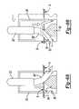
- FIG. 14is a cross-sectional view of a jaw portion according to additional features
- FIG. 15is a cross-sectional view of the jaw portion of FIG. 14 shown advancing through the tissue during actuation.
- FIG. 16is a cross-sectional view of the jaw portion of FIG. 15 shown with a captured portion of suture during retraction from the tissue.
- the apparatus 10generally includes a longitudinal shaft 12 extending between a jaw end 14 and a handle end 18 .
- the jaw end 14includes a first and second jaw member 20 and 22 respectively.
- the handle end 18includes a first and second handle member 24 and 26 respectively.
- relative actuation of the handles 24 and 26causes relative actuation between the first and second jaw members 20 and 22 .
- the first and second jaw members 20 and 22cooperate to pass a length of suture 30 through a pierced hole 32 formed in the tissue 34 ( FIG. 4 ).
- the needle 60forms a sharp point 92 on a first end for piercing the tissue 34 during a procedure.
- the needle 60further defines a hook 96 formed therein.
- the hook 96is operable to capture a portion of the suture 30 and draw the portion of suture 30 through the pierced hole 32 formed by the needle 60 .
- a length of suture 30is selected for the subject application.
- the suture 30is wrapped around the body 42 of the first jaw member 20 in a nesting relationship with the groove 56 .
- Opposite free ends 98extend away from the first jaw member 20 alongside the longitudinal shaft 12 and may be held taught by the surgeon. It is appreciated that the free ends 98 may be located into a secure position by other methods including retaining structure incorporated on the longitudinal shaft 12 , handle portions 24 , 26 or elsewhere on the apparatus 10 .
- Movement of the second handle 26 in a first direction D 1causes the rod to translate within the tubular portion 38 of the longitudinal shaft 12 .
- Linear translation of the rodimparts rotational movement of the second jaw member 22 about the pivot joint 40 (in a counterclockwise direction as viewed by FIG. 1 ).
- the surgeonhas a looped portion of suture 30 extending away from the second surface B of tissue 34 and a pair of free ends extending away from the first surface A.
- the surgeonmay then utilize the suture 30 in any desired manner for a given application.
- the suture 30may be cut at the looped portion and tied off, or one of the suture ends 98 ( FIG. 1 ) may alternatively be pulled through the hole 32 such that a continuous strand extends through the tissue 34 .
- a knob 100( FIG. 1 ) is operably interconnected to the needle 60 (such as by way of a wire or shaft).
- the knob 100may be pulled in a direction away from the first handle 24 to urge the needle 60 to retract into the distal end 84 of the second jaw 22 .
- the knob 100may be pushed toward the first handle 24 to urge the needle 60 to advance from the distal end 84 of the second jaw 22 .
- Rotation of the knob 100influences axial rotation of the needle 60 .
- the knob 100may comprise other configurations and/or be located elsewhere on the apparatus 10 .
- the second jaw member 102includes a pair of needles 110 , 112 extending from a distal end 114 . As will be described, this configuration is particularly useful for performing a mattress stitch.
- a surgeoninstead of removing a single assembly barrel and needle to insert a double barrel and needle assembly, a surgeon would leave the single barrel and needle attached and add a second barrel and needle when a mattress stitch is desired.
- a double barrel configurationFIG. 11
- a surgeonmay remove one of the needles 110 , 112 from the double barrel configuration when a single stitch is desired.
- the second jaw member 102is particularly useful for bridging a tear T in the tissue 130 . It is appreciated however that the apparatus may be used in other applications for different tissue arrangements.
- actuation of the second handle 26imparts rotational movement of the second jaw member 102 as described above.
- each needle 110 and 112concurrently penetrates and advances through the tissue 130 .
- the respective angled engagement surfaces 120 and 122 of the needles 110 and 112slidably advance along the first and second engagement surface 70 and 72 of the bridge 62 .
- each needle 110 and 112The slidable communication of the needles 110 and 112 along the angled engagement surfaces 70 and 72 of the bridge 62 causes each needle 110 and 112 to progressively deflect outwardly (away from each other) with respect to a longitudinal axis of the first jaw member 20 .
- the needles 110 and 112pass into engagement with respective portions of the suture 30 .
- Deflection of the needles 110 and 112allows hooks 134 and 136 to come into contact and capture portions of the suture 30 .
- Retraction of the second jaw member 102( FIG. 13 ) allows a pair of looped portions of suture 30 to be drawn through respective holes 140 and 142 in the tissue 130 .
- each end 98may be tied or secured according to the desired application.
- a first portion of the suture 30extends out of the first hole 140 and a second portion extends out of the second hole 142 .
- An intermediate portion of suture 30may be drawn toward the tissue 130 to bridge a distance between the first and second holes 140 and 142 .
- the second jaw member 204includes a pair of barrel portions 236 and 238 for accepting a pair of needles 240 and 242 therein.
- Each needle 240 and 242includes a complementary angled engagement surface 250 , 252 for slidably communicating with the first and second angled engagement surfaces 218 and 220 of the arms 216 extending from the first jaw portion 202 .
- Each needle 240 and 242forms a sharp point 256 and 258 for piercing the tissue 230 during a procedure and includes a hook 260 and 262 for capturing a respective portion of the suture 30 and drawing it through each pierced hole 270 and 272 respectively.
- each needle 240 and 242The slidable communication of the needles 240 and 242 along the angled engagement surfaces 218 and 220 of the arms 216 causes each needle 240 and 242 to progressively deflect inwardly (toward each other) with respect to a longitudinal axis of the first jaw member 202 .
- the needles 240 and 242pass into engagement with respective portions of the suture 30 .
- Deflection of the needles 240 and 242allows hooks 260 and 262 to come into contact and capture portions of the suture 30 .
- Retraction of the second jaw member 204( FIG. 16 ) allows a pair of looped portions of suture 30 to be drawn through respective holes 270 and 272 in the tissue 230 .
- a clamp 280may additionally be used to clamp a portion of the tissue 230 to the first jaw member 202 if desired during a procedure. As shown in FIG. 16 , a first portion of the suture 30 extends out of the first hole 270 and a second portion extends out of the second hole 272 . An intermediate portion of suture 30 (from the portion looped around a distal end of the first jaw member 202 ) may be drawn toward the tissue 230 to bridge a distance between the first and second holes 270 and 272 .
Landscapes
- Health & Medical Sciences (AREA)
- Life Sciences & Earth Sciences (AREA)
- Surgery (AREA)
- Heart & Thoracic Surgery (AREA)
- Engineering & Computer Science (AREA)
- Biomedical Technology (AREA)
- Nuclear Medicine, Radiotherapy & Molecular Imaging (AREA)
- Medical Informatics (AREA)
- Molecular Biology (AREA)
- Animal Behavior & Ethology (AREA)
- General Health & Medical Sciences (AREA)
- Public Health (AREA)
- Veterinary Medicine (AREA)
- Surgical Instruments (AREA)
Abstract
Description
Claims (37)
Priority Applications (2)
| Application Number | Priority Date | Filing Date | Title |
|---|---|---|---|
| US10/984,608US7722630B1 (en) | 2004-11-09 | 2004-11-09 | Method and apparatus for passing a suture through tissue |
| US12/777,704US8444659B2 (en) | 2004-11-09 | 2010-05-11 | Method and apparatus for passing a suture through tissue |
Applications Claiming Priority (1)
| Application Number | Priority Date | Filing Date | Title |
|---|---|---|---|
| US10/984,608US7722630B1 (en) | 2004-11-09 | 2004-11-09 | Method and apparatus for passing a suture through tissue |
Related Child Applications (1)
| Application Number | Title | Priority Date | Filing Date |
|---|---|---|---|
| US12/777,704DivisionUS8444659B2 (en) | 2004-11-09 | 2010-05-11 | Method and apparatus for passing a suture through tissue |
Publications (1)
| Publication Number | Publication Date |
|---|---|
| US7722630B1true US7722630B1 (en) | 2010-05-25 |
Family
ID=42184228
Family Applications (2)
| Application Number | Title | Priority Date | Filing Date |
|---|---|---|---|
| US10/984,608Expired - Fee RelatedUS7722630B1 (en) | 2004-11-09 | 2004-11-09 | Method and apparatus for passing a suture through tissue |
| US12/777,704Expired - Fee RelatedUS8444659B2 (en) | 2004-11-09 | 2010-05-11 | Method and apparatus for passing a suture through tissue |
Family Applications After (1)
| Application Number | Title | Priority Date | Filing Date |
|---|---|---|---|
| US12/777,704Expired - Fee RelatedUS8444659B2 (en) | 2004-11-09 | 2010-05-11 | Method and apparatus for passing a suture through tissue |
Country Status (1)
| Country | Link |
|---|---|
| US (2) | US7722630B1 (en) |
Cited By (44)
| Publication number | Priority date | Publication date | Assignee | Title |
|---|---|---|---|---|
| US20090182354A1 (en)* | 2008-01-15 | 2009-07-16 | Kenneth Blier | Surgical Stapling Apparatus |
| US20090259233A1 (en)* | 2008-04-11 | 2009-10-15 | Michael Bogart | Deployment System For Surgical Suture |
| US20100217282A1 (en)* | 2006-10-05 | 2010-08-26 | Tyco Healthcare Group Lp | Flexible endoscopic stitching devices |
| US20100222791A1 (en)* | 2004-11-09 | 2010-09-02 | Biomet Sports Medicine, Llc | Method and Apparatus for Passing a Suture Through Tissue |
| US20110040308A1 (en)* | 2008-06-13 | 2011-02-17 | Ramiro Cabrera | Endoscopic Stitching Devices |
| US20110082476A1 (en)* | 2009-10-06 | 2011-04-07 | Tyco Healthcare Group Lp | Handle Assembly for Endoscopic Suturing Device |
| WO2012154582A1 (en) | 2011-05-06 | 2012-11-15 | Ceterix Orthopedics, Inc. | Suture passer devices and methods |
| US8454631B2 (en) | 2006-10-05 | 2013-06-04 | Covidien Lp | Axial stitching devices |
| US20130184720A1 (en)* | 2012-01-13 | 2013-07-18 | Dallen Medical, Inc. | Actuator for band tensioning system |
| US20130345725A1 (en)* | 2008-11-07 | 2013-12-26 | Arthrex, Inc. | Suturing instrument for passing multiple sutures |
| US8628545B2 (en) | 2008-06-13 | 2014-01-14 | Covidien Lp | Endoscopic stitching devices |
| USD708746S1 (en) | 2009-06-10 | 2014-07-08 | Covidien Lp | Handle for surgical device |
| WO2014109871A1 (en)* | 2013-01-08 | 2014-07-17 | Sanovas, Inc. | Precision directed medical instruments |
| US8801727B2 (en) | 2011-07-08 | 2014-08-12 | Smith & Nephew, Inc. | Orthopedic suture passer and method |
| US8882834B2 (en) | 2011-07-08 | 2014-11-11 | Smith & Nephew, Inc. | Soft tissue repair |
| US8888849B2 (en) | 2011-07-08 | 2014-11-18 | Smith & Nephew, Inc. | Soft tissue repair |
| US8911456B2 (en) | 2007-07-03 | 2014-12-16 | Ceterix Orthopaedics, Inc. | Methods and devices for preventing tissue bridging while suturing |
| US8920441B2 (en) | 2007-07-03 | 2014-12-30 | Ceterix Orthopaedics, Inc. | Methods of meniscus repair |
| US8951263B2 (en) | 2011-07-08 | 2015-02-10 | Smith & Nephew, Inc. | Orthopedic suture passer and method |
| US8968340B2 (en) | 2011-02-23 | 2015-03-03 | Covidien Lp | Single actuating jaw flexible endolumenal stitching device |
| US9011454B2 (en) | 2009-11-09 | 2015-04-21 | Ceterix Orthopaedics, Inc. | Suture passer with radiused upper jaw |
| US20150238181A1 (en)* | 2012-09-28 | 2015-08-27 | Tensor Surgical, Inc. | Transosseous attachment method and instruments |
| CN104939875A (en)* | 2013-12-16 | 2015-09-30 | 赛特里克斯整形公司 | Automatically reloading suture passer devices and methods |
| US20150297215A1 (en)* | 2014-04-08 | 2015-10-22 | Michael J. Hendricksen | Suture passers adapted for use in constrained regions |
| US9211119B2 (en) | 2007-07-03 | 2015-12-15 | Ceterix Orthopaedics, Inc. | Suture passers and methods of passing suture |
| US9247935B2 (en) | 2013-09-23 | 2016-02-02 | Ceterix Orthopaedics, Inc. | Arthroscopic knot pusher and suture cutter |
| US9314234B2 (en) | 2007-07-03 | 2016-04-19 | Ceterix Orthopaedics, Inc. | Pre-tied surgical knots for use with suture passers |
| US9357997B2 (en) | 2011-07-08 | 2016-06-07 | Smith & Nephew, Inc. | Suture passer and method |
| US20160183934A1 (en)* | 2014-07-16 | 2016-06-30 | Tensor Surgical, Inc. | Passive retrieving interosseous suture passing device |
| US9468434B2 (en) | 2014-06-03 | 2016-10-18 | Covidien Lp | Stitching end effector |
| US9662105B2 (en) | 2011-07-08 | 2017-05-30 | Smith & Nephew, Inc. | Suture passer and method |
| US9700299B2 (en) | 2011-05-06 | 2017-07-11 | Ceterix Orthopaedics, Inc. | Suture passer devices and methods |
| US9848868B2 (en) | 2011-01-10 | 2017-12-26 | Ceterix Orthopaedics, Inc. | Suture methods for forming locking loops stitches |
| US9913638B2 (en) | 2011-01-10 | 2018-03-13 | Ceterix Orthopaedics, Inc. | Transosteal anchoring methods for tissue repair |
| US20180256152A1 (en)* | 2013-06-07 | 2018-09-13 | Biomet Sports Medicine, Llc | Method and apparatus for coupling soft tissue to bone |
| US10092286B2 (en) | 2015-05-27 | 2018-10-09 | Covidien Lp | Suturing loading unit |
| US10226245B2 (en) | 2015-07-21 | 2019-03-12 | Ceterix Orthopaedics, Inc. | Automatically reloading suture passer devices that prevent entanglement |
| US10405853B2 (en) | 2015-10-02 | 2019-09-10 | Ceterix Orthpaedics, Inc. | Knot tying accessory |
| US10441273B2 (en) | 2007-07-03 | 2019-10-15 | Ceterix Orthopaedics, Inc. | Pre-tied surgical knots for use with suture passers |
| US10524778B2 (en) | 2011-09-28 | 2020-01-07 | Ceterix Orthopaedics | Suture passers adapted for use in constrained regions |
| US10542970B2 (en) | 2016-05-31 | 2020-01-28 | Covidien Lp | Endoscopic stitching device |
| US11197665B2 (en) | 2018-08-06 | 2021-12-14 | Covidien Lp | Needle reload device for use with endostitch device |
| US11457912B2 (en) | 2016-06-02 | 2022-10-04 | Parcus Medical, Llc | Suture tool and method of use |
| US11744575B2 (en) | 2009-11-09 | 2023-09-05 | Ceterix Orthopaedics, Inc. | Suture passer devices and methods |
Families Citing this family (5)
| Publication number | Priority date | Publication date | Assignee | Title |
|---|---|---|---|---|
| CA2702952C (en) | 2007-10-27 | 2017-01-03 | Parcus Medical, Llc | Suture anchor |
| US9119617B2 (en)* | 2012-03-16 | 2015-09-01 | Ethicon, Inc. | Clamping devices for dispensing surgical fasteners into soft media |
| US8740919B2 (en)* | 2012-03-16 | 2014-06-03 | Ethicon, Inc. | Devices for dispensing surgical fasteners into tissue while simultaneously generating external marks that mirror the number and location of the dispensed surgical fasteners |
| WO2015171962A1 (en) | 2014-05-07 | 2015-11-12 | Bart Bracy | Multipart suture |
| US11517301B2 (en) | 2016-06-02 | 2022-12-06 | Parcus Medical, Llc | Surgical tool and method of use |
Citations (9)
| Publication number | Priority date | Publication date | Assignee | Title |
|---|---|---|---|---|
| US5522820A (en)* | 1993-01-15 | 1996-06-04 | Arthrotech | Method and apparatus for suturing tissue |
| US5707379A (en)* | 1995-10-20 | 1998-01-13 | Coral Medical | Method and apparatus for intracorporeal suturing |
| US5730747A (en) | 1995-06-07 | 1998-03-24 | Smith & Nephew, Inc. | Suture passing forceps |
| US5935149A (en) | 1995-06-07 | 1999-08-10 | Smith & Nephew Inc. | Suturing tissue |
| US6051006A (en) | 1999-04-12 | 2000-04-18 | Smith & Nephew, Inc. | Suture-passing forceps |
| US20030078599A1 (en) | 2001-10-23 | 2003-04-24 | O'quinn Philip S. | Endoscopic capsular suture plication instrument and method |
| US20030083695A1 (en) | 2001-08-06 | 2003-05-01 | Morris John K. | Compact suture punch with malleable needle |
| US6605096B1 (en)* | 2001-07-20 | 2003-08-12 | Opus Medical Inc, | Percutaneous suturing apparatus and method |
| US6770084B1 (en)* | 2002-06-26 | 2004-08-03 | Opus Medical, Inc. | Suture capture device |
Family Cites Families (1)
| Publication number | Priority date | Publication date | Assignee | Title |
|---|---|---|---|---|
| US7722630B1 (en) | 2004-11-09 | 2010-05-25 | Biomet Sports Medicine, Llc | Method and apparatus for passing a suture through tissue |
- 2004
- 2004-11-09USUS10/984,608patent/US7722630B1/ennot_activeExpired - Fee Related
- 2010
- 2010-05-11USUS12/777,704patent/US8444659B2/ennot_activeExpired - Fee Related
Patent Citations (9)
| Publication number | Priority date | Publication date | Assignee | Title |
|---|---|---|---|---|
| US5522820A (en)* | 1993-01-15 | 1996-06-04 | Arthrotech | Method and apparatus for suturing tissue |
| US5730747A (en) | 1995-06-07 | 1998-03-24 | Smith & Nephew, Inc. | Suture passing forceps |
| US5935149A (en) | 1995-06-07 | 1999-08-10 | Smith & Nephew Inc. | Suturing tissue |
| US5707379A (en)* | 1995-10-20 | 1998-01-13 | Coral Medical | Method and apparatus for intracorporeal suturing |
| US6051006A (en) | 1999-04-12 | 2000-04-18 | Smith & Nephew, Inc. | Suture-passing forceps |
| US6605096B1 (en)* | 2001-07-20 | 2003-08-12 | Opus Medical Inc, | Percutaneous suturing apparatus and method |
| US20030083695A1 (en) | 2001-08-06 | 2003-05-01 | Morris John K. | Compact suture punch with malleable needle |
| US20030078599A1 (en) | 2001-10-23 | 2003-04-24 | O'quinn Philip S. | Endoscopic capsular suture plication instrument and method |
| US6770084B1 (en)* | 2002-06-26 | 2004-08-03 | Opus Medical, Inc. | Suture capture device |
Cited By (84)
| Publication number | Priority date | Publication date | Assignee | Title |
|---|---|---|---|---|
| US20100222791A1 (en)* | 2004-11-09 | 2010-09-02 | Biomet Sports Medicine, Llc | Method and Apparatus for Passing a Suture Through Tissue |
| US8444659B2 (en) | 2004-11-09 | 2013-05-21 | Biomet Sports Medicine, Llc | Method and apparatus for passing a suture through tissue |
| US9113860B2 (en) | 2006-10-05 | 2015-08-25 | Covidien Lp | Flexible endoscopic stitching devices |
| US8506581B2 (en) | 2006-10-05 | 2013-08-13 | Covidien Lp | Flexible endoscopic stitching devices |
| US20100217282A1 (en)* | 2006-10-05 | 2010-08-26 | Tyco Healthcare Group Lp | Flexible endoscopic stitching devices |
| US8968342B2 (en) | 2006-10-05 | 2015-03-03 | Covidien Lp | Flexible endoscopic stitching devices |
| US8496674B2 (en) | 2006-10-05 | 2013-07-30 | Covidien Lp | Flexible endoscopic stitching devices |
| US8747424B2 (en) | 2006-10-05 | 2014-06-10 | Covidien Lp | Flexible endoscopic stitching devices |
| US8454631B2 (en) | 2006-10-05 | 2013-06-04 | Covidien Lp | Axial stitching devices |
| US8911456B2 (en) | 2007-07-03 | 2014-12-16 | Ceterix Orthopaedics, Inc. | Methods and devices for preventing tissue bridging while suturing |
| US10441273B2 (en) | 2007-07-03 | 2019-10-15 | Ceterix Orthopaedics, Inc. | Pre-tied surgical knots for use with suture passers |
| US9314234B2 (en) | 2007-07-03 | 2016-04-19 | Ceterix Orthopaedics, Inc. | Pre-tied surgical knots for use with suture passers |
| US8920441B2 (en) | 2007-07-03 | 2014-12-30 | Ceterix Orthopaedics, Inc. | Methods of meniscus repair |
| US9211119B2 (en) | 2007-07-03 | 2015-12-15 | Ceterix Orthopaedics, Inc. | Suture passers and methods of passing suture |
| US20090182354A1 (en)* | 2008-01-15 | 2009-07-16 | Kenneth Blier | Surgical Stapling Apparatus |
| US9706990B2 (en) | 2008-01-15 | 2017-07-18 | Covidien Lp | Surgical stapling apparatus |
| US8490851B2 (en)* | 2008-01-15 | 2013-07-23 | Covidien Lp | Surgical stapling apparatus |
| US8864776B2 (en) | 2008-04-11 | 2014-10-21 | Covidien Lp | Deployment system for surgical suture |
| US20090259233A1 (en)* | 2008-04-11 | 2009-10-15 | Michael Bogart | Deployment System For Surgical Suture |
| US11849936B2 (en) | 2008-06-13 | 2023-12-26 | Covidien Lp | Endoscopic stitching devices |
| US10945722B2 (en) | 2008-06-13 | 2021-03-16 | Covidien Lp | Endoscopic stitching devices |
| US8628545B2 (en) | 2008-06-13 | 2014-01-14 | Covidien Lp | Endoscopic stitching devices |
| US10413289B2 (en) | 2008-06-13 | 2019-09-17 | Covidien Lp | Endoscopic stitching devices |
| US20110040308A1 (en)* | 2008-06-13 | 2011-02-17 | Ramiro Cabrera | Endoscopic Stitching Devices |
| US9393010B2 (en)* | 2008-11-07 | 2016-07-19 | Arthrex, Inc. | Suturing instrument for passing multiple sutures |
| US20130345725A1 (en)* | 2008-11-07 | 2013-12-26 | Arthrex, Inc. | Suturing instrument for passing multiple sutures |
| USD708746S1 (en) | 2009-06-10 | 2014-07-08 | Covidien Lp | Handle for surgical device |
| US8490713B2 (en) | 2009-10-06 | 2013-07-23 | Covidien Lp | Handle assembly for endoscopic suturing device |
| US9615824B2 (en) | 2009-10-06 | 2017-04-11 | Covidien Lp | Handle assembly for endoscopic suturing device |
| US20110082476A1 (en)* | 2009-10-06 | 2011-04-07 | Tyco Healthcare Group Lp | Handle Assembly for Endoscopic Suturing Device |
| US11744575B2 (en) | 2009-11-09 | 2023-09-05 | Ceterix Orthopaedics, Inc. | Suture passer devices and methods |
| US10004492B2 (en) | 2009-11-09 | 2018-06-26 | Ceterix Orthopaedics, Inc. | Suture passer with radiused upper jaw |
| US9011454B2 (en) | 2009-11-09 | 2015-04-21 | Ceterix Orthopaedics, Inc. | Suture passer with radiused upper jaw |
| US9913638B2 (en) | 2011-01-10 | 2018-03-13 | Ceterix Orthopaedics, Inc. | Transosteal anchoring methods for tissue repair |
| US9848868B2 (en) | 2011-01-10 | 2017-12-26 | Ceterix Orthopaedics, Inc. | Suture methods for forming locking loops stitches |
| US10561410B2 (en) | 2011-01-10 | 2020-02-18 | Ceterix Orthopaedics, Inc. | Transosteal anchoring methods for tissue repair |
| US10987095B2 (en) | 2011-01-10 | 2021-04-27 | Ceterix Orthopaedics, Inc. | Suture methods for forming locking loops stitches |
| US8968340B2 (en) | 2011-02-23 | 2015-03-03 | Covidien Lp | Single actuating jaw flexible endolumenal stitching device |
| EP2704642A4 (en)* | 2011-05-06 | 2014-10-29 | Ceterix Orthopaedics Inc | Suture passer devices and methods |
| US9247934B2 (en) | 2011-05-06 | 2016-02-02 | Ceterix Orthopaedics, Inc. | Suture passer devices and methods |
| WO2012154582A1 (en) | 2011-05-06 | 2012-11-15 | Ceterix Orthopedics, Inc. | Suture passer devices and methods |
| US9700299B2 (en) | 2011-05-06 | 2017-07-11 | Ceterix Orthopaedics, Inc. | Suture passer devices and methods |
| US10758222B2 (en) | 2011-05-06 | 2020-09-01 | Ceterix Orthopaedics, Inc. | Meniscus repair |
| US10188382B2 (en) | 2011-05-06 | 2019-01-29 | Ceterix Orthopaedics, Inc. | Suture passer devices and methods |
| US11006947B2 (en) | 2011-07-08 | 2021-05-18 | Smith & Nephew, Inc. | Suture passer and method |
| US8882834B2 (en) | 2011-07-08 | 2014-11-11 | Smith & Nephew, Inc. | Soft tissue repair |
| US9662105B2 (en) | 2011-07-08 | 2017-05-30 | Smith & Nephew, Inc. | Suture passer and method |
| US8801727B2 (en) | 2011-07-08 | 2014-08-12 | Smith & Nephew, Inc. | Orthopedic suture passer and method |
| US8888849B2 (en) | 2011-07-08 | 2014-11-18 | Smith & Nephew, Inc. | Soft tissue repair |
| US8951263B2 (en) | 2011-07-08 | 2015-02-10 | Smith & Nephew, Inc. | Orthopedic suture passer and method |
| US10335138B2 (en) | 2011-07-08 | 2019-07-02 | Smith & Nephew, Inc. | Suture passer and method |
| US9357997B2 (en) | 2011-07-08 | 2016-06-07 | Smith & Nephew, Inc. | Suture passer and method |
| US10524778B2 (en) | 2011-09-28 | 2020-01-07 | Ceterix Orthopaedics | Suture passers adapted for use in constrained regions |
| US20130184720A1 (en)* | 2012-01-13 | 2013-07-18 | Dallen Medical, Inc. | Actuator for band tensioning system |
| US9345465B2 (en)* | 2012-01-13 | 2016-05-24 | Dallen Medical, Inc. | Actuator for band tensioning system |
| US20150238181A1 (en)* | 2012-09-28 | 2015-08-27 | Tensor Surgical, Inc. | Transosseous attachment method and instruments |
| US10433821B2 (en) | 2013-01-08 | 2019-10-08 | Sanovas Intellectual Property, Llc | Precision directed medical instruments |
| WO2014109871A1 (en)* | 2013-01-08 | 2014-07-17 | Sanovas, Inc. | Precision directed medical instruments |
| US20180256152A1 (en)* | 2013-06-07 | 2018-09-13 | Biomet Sports Medicine, Llc | Method and apparatus for coupling soft tissue to bone |
| US10842481B2 (en)* | 2013-06-07 | 2020-11-24 | Biomet Sports Medicine, Llc | Method and apparatus for coupling soft tissue to bone |
| US10820899B2 (en) | 2013-09-23 | 2020-11-03 | Ceterix Orthopaedics, Inc. | Arthroscopic knot pusher and suture cutter |
| US10143464B2 (en) | 2013-09-23 | 2018-12-04 | Ceterix Orthopaedics, Inc. | Arthroscopic knot pusher and suture cutter |
| US9247935B2 (en) | 2013-09-23 | 2016-02-02 | Ceterix Orthopaedics, Inc. | Arthroscopic knot pusher and suture cutter |
| US9332980B2 (en) | 2013-09-23 | 2016-05-10 | Ceterix Orthopaedics, Inc. | Arthroscopic knot pusher and suture cutter |
| US9492162B2 (en) | 2013-12-16 | 2016-11-15 | Ceterix Orthopaedics, Inc. | Automatically reloading suture passer devices and methods |
| CN104939875A (en)* | 2013-12-16 | 2015-09-30 | 赛特里克斯整形公司 | Automatically reloading suture passer devices and methods |
| CN104939875B (en)* | 2013-12-16 | 2019-07-26 | 赛特里克斯整形公司 | Automatically suture passer device and method are reloaded |
| US10524779B2 (en) | 2013-12-16 | 2020-01-07 | Ceterix Orthopaedics, Inc. | Automatically reloading suture passer devices and methods |
| US20150297215A1 (en)* | 2014-04-08 | 2015-10-22 | Michael J. Hendricksen | Suture passers adapted for use in constrained regions |
| US10537321B2 (en)* | 2014-04-08 | 2020-01-21 | Ceterix Orthopaedics, Inc. | Suture passers adapted for use in constrained regions |
| US9468434B2 (en) | 2014-06-03 | 2016-10-18 | Covidien Lp | Stitching end effector |
| US10245024B2 (en) | 2014-06-03 | 2019-04-02 | Covidien Lp | Stitching end effector |
| US10966708B2 (en) | 2014-06-03 | 2021-04-06 | Covidien Lp | Stitching end effector |
| US9839418B2 (en)* | 2014-07-16 | 2017-12-12 | Tensor Surgical, Inc. | Passive retrieving interosseous suture passing device |
| US20160183934A1 (en)* | 2014-07-16 | 2016-06-30 | Tensor Surgical, Inc. | Passive retrieving interosseous suture passing device |
| US10799234B2 (en) | 2015-05-27 | 2020-10-13 | Covidien Lp | Suturing loading unit |
| US10092286B2 (en) | 2015-05-27 | 2018-10-09 | Covidien Lp | Suturing loading unit |
| US10806442B2 (en) | 2015-07-21 | 2020-10-20 | Ceterix Orthopaedics, Inc. | Automatically reloading suture passer devices that prevent entanglement |
| US10226245B2 (en) | 2015-07-21 | 2019-03-12 | Ceterix Orthopaedics, Inc. | Automatically reloading suture passer devices that prevent entanglement |
| US10405853B2 (en) | 2015-10-02 | 2019-09-10 | Ceterix Orthpaedics, Inc. | Knot tying accessory |
| US10542970B2 (en) | 2016-05-31 | 2020-01-28 | Covidien Lp | Endoscopic stitching device |
| US11457912B2 (en) | 2016-06-02 | 2022-10-04 | Parcus Medical, Llc | Suture tool and method of use |
| US12274436B2 (en) | 2016-06-02 | 2025-04-15 | Parcus Medical, Llc | Suture tool and method of use |
| US11197665B2 (en) | 2018-08-06 | 2021-12-14 | Covidien Lp | Needle reload device for use with endostitch device |
Also Published As
| Publication number | Publication date |
|---|---|
| US20100222791A1 (en) | 2010-09-02 |
| US8444659B2 (en) | 2013-05-21 |
Similar Documents
| Publication | Publication Date | Title |
|---|---|---|
| US7722630B1 (en) | Method and apparatus for passing a suture through tissue | |
| JP5512270B2 (en) | System for suture manipulation | |
| EP2373225B1 (en) | Arthroscopic suture passing devices and methods | |
| US9226747B2 (en) | Medical implement for manipulating sutures particularly useful in arthroscopic surgery | |
| US8591527B2 (en) | Suture passer with suture capturing articulating jaw at distal end for suturing in arthroscopic surgery | |
| US8663250B2 (en) | Suturing instrument with dual needles and method of passing suture | |
| US9155534B2 (en) | Side-loaded medical implement particularly useful in arthroscopic surgery | |
| US6893448B2 (en) | Endoscopic capsular suture plication instrument and method | |
| CN109843187B (en) | Suture passer and grasper instruments and methods | |
| US20030233106A1 (en) | Suture passing instrument | |
| JP5357035B2 (en) | Shape memory filament for suture manipulation | |
| US20110118760A1 (en) | Suture passer | |
| JP2009279428A (en) | Endoscopic organ retraction system and method of using the same |
Legal Events
| Date | Code | Title | Description |
|---|---|---|---|
| AS | Assignment | Owner name:ARTHROTEK, INC.,INDIANA Free format text:ASSIGNMENT OF ASSIGNORS INTEREST;ASSIGNORS:STONE, KEVIN T.;WALTERS, TROY M.;REEL/FRAME:015990/0404 Effective date:20041104 | |
| AS | Assignment | Owner name:BIOMET SPORTS MEDICINE, INC.,INDIANA Free format text:CHANGE OF NAME;ASSIGNOR:ARTHROTEK, INC.;REEL/FRAME:019040/0720 Effective date:20061227 Owner name:BIOMET SPORTS MEDICINE, INC., INDIANA Free format text:CHANGE OF NAME;ASSIGNOR:ARTHROTEK, INC.;REEL/FRAME:019040/0720 Effective date:20061227 | |
| AS | Assignment | Owner name:BANK OF AMERICA, N.A., AS ADMINISTRATIVE AGENT FOR Free format text:SECURITY AGREEMENT;ASSIGNORS:LVB ACQUISITION, INC.;BIOMET, INC.;REEL/FRAME:020362/0001 Effective date:20070925 | |
| AS | Assignment | Owner name:BIOMET SPORTS MEDICINE, LLC,INDIANA Free format text:CHANGE OF NAME;ASSIGNOR:BIOMET SPORTS MEDICINE, INC.;REEL/FRAME:021387/0441 Effective date:20080227 Owner name:BIOMET SPORTS MEDICINE, LLC, INDIANA Free format text:CHANGE OF NAME;ASSIGNOR:BIOMET SPORTS MEDICINE, INC.;REEL/FRAME:021387/0441 Effective date:20080227 | |
| STCF | Information on status: patent grant | Free format text:PATENTED CASE | |
| FPAY | Fee payment | Year of fee payment:4 | |
| AS | Assignment | Owner name:BIOMET, INC., INDIANA Free format text:RELEASE OF SECURITY INTEREST IN PATENTS RECORDED AT REEL 020362/ FRAME 0001;ASSIGNOR:BANK OF AMERICA, N.A., AS ADMINISTRATIVE AGENT;REEL/FRAME:037155/0133 Effective date:20150624 Owner name:LVB ACQUISITION, INC., INDIANA Free format text:RELEASE OF SECURITY INTEREST IN PATENTS RECORDED AT REEL 020362/ FRAME 0001;ASSIGNOR:BANK OF AMERICA, N.A., AS ADMINISTRATIVE AGENT;REEL/FRAME:037155/0133 Effective date:20150624 | |
| MAFP | Maintenance fee payment | Free format text:PAYMENT OF MAINTENANCE FEE, 8TH YEAR, LARGE ENTITY (ORIGINAL EVENT CODE: M1552) Year of fee payment:8 | |
| AS | Assignment | Owner name:BIOMET U.S. RECONSTRUCTION, LLC, INDIANA Free format text:ASSIGNMENT OF ASSIGNORS INTEREST;ASSIGNOR:BIOMET SPORTS MEDICINE, LLC;REEL/FRAME:045935/0497 Effective date:20171103 Owner name:BIOMET, INC., INDIANA Free format text:ASSIGNMENT OF ASSIGNORS INTEREST;ASSIGNOR:BIOMET U.S. RECONSTRUCTION, LLC;REEL/FRAME:045935/0557 Effective date:20171103 Owner name:BIOMET MANUFACTURING, LLC, INDIANA Free format text:ASSIGNMENT OF ASSIGNORS INTEREST;ASSIGNOR:ZB MANUFACTURING, LLC;REEL/FRAME:045935/0673 Effective date:20171103 Owner name:ZB MANUFACTURING, LLC, INDIANA Free format text:ASSIGNMENT OF ASSIGNORS INTEREST;ASSIGNOR:BIOMET, INC.;REEL/FRAME:045935/0570 Effective date:20171103 | |
| FEPP | Fee payment procedure | Free format text:MAINTENANCE FEE REMINDER MAILED (ORIGINAL EVENT CODE: REM.); ENTITY STATUS OF PATENT OWNER: LARGE ENTITY | |
| LAPS | Lapse for failure to pay maintenance fees | Free format text:PATENT EXPIRED FOR FAILURE TO PAY MAINTENANCE FEES (ORIGINAL EVENT CODE: EXP.); ENTITY STATUS OF PATENT OWNER: LARGE ENTITY | |
| STCH | Information on status: patent discontinuation | Free format text:PATENT EXPIRED DUE TO NONPAYMENT OF MAINTENANCE FEES UNDER 37 CFR 1.362 | |
| FP | Lapsed due to failure to pay maintenance fee | Effective date:20220525 |