US7722555B2 - Lockable hinge - Google Patents
Lockable hingeDownload PDFInfo
- Publication number
- US7722555B2 US7722555B2US11/768,868US76886807AUS7722555B2US 7722555 B2US7722555 B2US 7722555B2US 76886807 AUS76886807 AUS 76886807AUS 7722555 B2US7722555 B2US 7722555B2
- Authority
- US
- United States
- Prior art keywords
- hinge
- flexion
- stop
- arm
- toggle
- Prior art date
- Legal status (The legal status is an assumption and is not a legal conclusion. Google has not performed a legal analysis and makes no representation as to the accuracy of the status listed.)
- Expired - Lifetime, expires
Links
Images


Classifications
- A—HUMAN NECESSITIES
- A61—MEDICAL OR VETERINARY SCIENCE; HYGIENE
- A61F—FILTERS IMPLANTABLE INTO BLOOD VESSELS; PROSTHESES; DEVICES PROVIDING PATENCY TO, OR PREVENTING COLLAPSING OF, TUBULAR STRUCTURES OF THE BODY, e.g. STENTS; ORTHOPAEDIC, NURSING OR CONTRACEPTIVE DEVICES; FOMENTATION; TREATMENT OR PROTECTION OF EYES OR EARS; BANDAGES, DRESSINGS OR ABSORBENT PADS; FIRST-AID KITS
- A61F5/00—Orthopaedic methods or devices for non-surgical treatment of bones or joints; Nursing devices ; Anti-rape devices
- A61F5/01—Orthopaedic devices, e.g. long-term immobilising or pressure directing devices for treating broken or deformed bones such as splints, casts or braces
- A61F5/0102—Orthopaedic devices, e.g. long-term immobilising or pressure directing devices for treating broken or deformed bones such as splints, casts or braces specially adapted for correcting deformities of the limbs or for supporting them; Ortheses, e.g. with articulations
- A61F5/0123—Orthopaedic devices, e.g. long-term immobilising or pressure directing devices for treating broken or deformed bones such as splints, casts or braces specially adapted for correcting deformities of the limbs or for supporting them; Ortheses, e.g. with articulations for the knees
- A—HUMAN NECESSITIES
- A61—MEDICAL OR VETERINARY SCIENCE; HYGIENE
- A61F—FILTERS IMPLANTABLE INTO BLOOD VESSELS; PROSTHESES; DEVICES PROVIDING PATENCY TO, OR PREVENTING COLLAPSING OF, TUBULAR STRUCTURES OF THE BODY, e.g. STENTS; ORTHOPAEDIC, NURSING OR CONTRACEPTIVE DEVICES; FOMENTATION; TREATMENT OR PROTECTION OF EYES OR EARS; BANDAGES, DRESSINGS OR ABSORBENT PADS; FIRST-AID KITS
- A61F5/00—Orthopaedic methods or devices for non-surgical treatment of bones or joints; Nursing devices ; Anti-rape devices
- A61F5/01—Orthopaedic devices, e.g. long-term immobilising or pressure directing devices for treating broken or deformed bones such as splints, casts or braces
- A61F5/0102—Orthopaedic devices, e.g. long-term immobilising or pressure directing devices for treating broken or deformed bones such as splints, casts or braces specially adapted for correcting deformities of the limbs or for supporting them; Ortheses, e.g. with articulations
- A61F2005/0132—Additional features of the articulation
- A61F2005/0137—Additional features of the articulation with two parallel pivots
- A—HUMAN NECESSITIES
- A61—MEDICAL OR VETERINARY SCIENCE; HYGIENE
- A61F—FILTERS IMPLANTABLE INTO BLOOD VESSELS; PROSTHESES; DEVICES PROVIDING PATENCY TO, OR PREVENTING COLLAPSING OF, TUBULAR STRUCTURES OF THE BODY, e.g. STENTS; ORTHOPAEDIC, NURSING OR CONTRACEPTIVE DEVICES; FOMENTATION; TREATMENT OR PROTECTION OF EYES OR EARS; BANDAGES, DRESSINGS OR ABSORBENT PADS; FIRST-AID KITS
- A61F5/00—Orthopaedic methods or devices for non-surgical treatment of bones or joints; Nursing devices ; Anti-rape devices
- A61F5/01—Orthopaedic devices, e.g. long-term immobilising or pressure directing devices for treating broken or deformed bones such as splints, casts or braces
- A61F5/0102—Orthopaedic devices, e.g. long-term immobilising or pressure directing devices for treating broken or deformed bones such as splints, casts or braces specially adapted for correcting deformities of the limbs or for supporting them; Ortheses, e.g. with articulations
- A61F2005/0132—Additional features of the articulation
- A61F2005/0158—Additional features of the articulation with locking means
Definitions
- the present inventionrelates to hinges for orthopedic braces.
- the present lockable hingewhen used in combination with a knee brace, provides a locking mode to immobilize the knee joint, and a free range of motion mode for flexing the knee.
- instabilitiesthat compromise their ability to ambulate and/or stand.
- These instabilitiescould include musculo-skeletal disorders such as quadriceps deficiencies, or neurological diseases such as muscular dystrophy, multiple sclerosis and polio.
- These instabilitiesinterfere with the ability of the brain to properly control the muscle groups that are essential for ambulation and/or standing.
- people who have suffered strokes or spinal cord injuriesalso have difficulty controlling these muscle groups.
- walking and standingcan be challenging or impossible. Bracing the person's leg so that he or she cannot bend his or her knee helps the person to stand and walk.
- a variety of leg braces that prevent knee flexionare available.
- a hinge manufactured by Townsend Design and marketed under the name Trigger Lockenables a person to switch between a locked mode and an unlocked mode.
- the hingeIn the locked mode, the hinge is freely rotatable between a first flexion angle and a second, maximum, flexion angle.
- the hingeautomatically locks, such that the hinge cannot reach a flexion angle greater than the first flexion angle.
- the personBy rotating a lever, the person can unlock the hinge so that the hinge can reach a flexion angle greater than the first flexion angle.
- By rotating a second leverthe person can place the hinge in the unlocked mode.
- the hingeIn the unlocked mode the hinge is freely rotatable and does not lock when it reaches a flexion angle less than the first flexion angle.
- a hinge manufactured by dj Orthopedics of Vista, Calif., and described in U.S. Pat. Nos. 5,292,303 and 5,409,449also enables a person to switch between a locked mode and an unlocked mode.
- the hingeincludes a lever that protrudes in a substantially radial direction.
- a springbiases the lever toward a locked position in which the lever interferes with rotation of the hinge arms.
- the hingeis locked at full extension.
- the leveris movable to an unlocked position in which the lever does not interfere with rotation of the hinge arms.
- the hingeis freely rotatable between full extension and approximately 120° of flexion.
- a latch secured to an edge of the hinge platesis selectively engageable with the lever to hold the lever in the unlocked position.
- the hingeis oriented at any angle short of full extension, and the latch is disengaged from the lever, the lever is biased toward the locked position.
- one of the hinge armsobstructs the lever, preventing the lever from reaching the locked position.
- the hinge armno longer obstructs the lever, and the lever snaps into the locked position.
- Another hinge manufactured by dj Orthopedicsalso enables a person to switch between a locked mode and an unlocked mode.
- the hingedoes not lock automatically upon reaching a pre-determined flexion angle.
- the hingeincludes a two-position switch that is slidable in the anterior/posterior direction. When the switch is in the posterior position, the hinge is freely rotatable between full extension and approximately 120° of flexion. When the hinge is at full extension, the wearer may slide the switch to the anterior position, where the switch locks the hinge at full extension.
- Another hinge manufactured by dj Orthopedics, and described in U.S. Pat. No. 5,921,946also enables a person to switch between a locked mode and an unlocked mode. This hinge also does not lock automatically upon reaching a pre-determined flexion angle.
- One of the hinge platesincludes a locking switch that is slidable toward and away from the other hinge plate. When the switch is slid toward the opposite hinge plate, it engages one of a plurality of slots on the opposite hinge plate, preventing rotation of the hinge. The slots are positioned such that the hinge may be locked at a plurality of different angles of flexion, including full extension. When the switch is slid away from the opposite hinge plate, it disengages the slot and the hinge becomes freely rotatable.
- the hingefurther includes an extension-limiting stop and a flexion-limiting stop.
- Each stopis slidable between a plurality of positions to set a maximum extension/flexion range for the hinge. In each position, each stop engages a different land on one of the hinge plates to define the extension/flexion limit.
- the preferred embodiments of the lockable hingehave several features, no single one of which is solely responsible for their desirable attributes. Without limiting the scope of this lockable hinge as expressed by the claims that follow, its more prominent features will now be discussed briefly. After considering this discussion, and particularly after reading the section entitled “Detailed Description of the Preferred Embodiments,” one will understand how the features of the preferred embodiments provide advantages, which include easy conversion between a locked mode and a free range of motion mode, thus eliminating the need to remove and reapply a brace into which the hinge is incorporated.
- a preferred embodiment of the present lockable hingecomprises a lockable hinge for use in an orthopedic brace.
- the hingecomprises a hinge plate, an arm rotatably mounted to the hinge plate, the arm being rotatable about a hinge axis, and a flexion stop.
- the flexion stopis movable in a direction substantially parallel to the hinge axis between a first position in which the flexion stop limits a range of flexion of the arm, and a second position in which the flexion stop does not limit a range of flexion of the arm.
- the armWhen the arm occupies a first flexion range, the arm preferably maintains the flexion stop in the first position. When the arm occupies a second flexion range, the arm preferably does not maintain the flexion stop in the first position. When the arm occupies the second flexion range, a flexion abutment face on the arm preferably cooperates with a flexion abutment face on the flexion stop to limit a range of flexion of the hinge.
- the lockable hingemay further comprise a toggle that is selectively engageable with the flexion stop.
- the toggledoes not engage the flexion stop, preferably the flexion stop moves toward the second position when the arm occupies the second flexion range.
- the toggle engages the flexion stoppreferably the flexion stop remains in the first position when the arm occupies the second flexion range.
- the lockable hingemay further comprise a second arm rotatably mounted to the hinge plate, the second arm being rotatable about a second hinge axis.
- the lockable hingemay further comprise an extension stop.
- the hingecomprises a hinge plate having a first aperture defining a first hinge axis and a second aperture defining a second hinge axis.
- a first armis secured to the hinge plate such that the first arm is rotatable about the first hinge axis.
- a second armis secured to the hinge plate such that the second arm is rotatable about the second hinge axis.
- the hingefurther comprises a flexion stop.
- the flexion stopis selectively positionable within a recess in the hinge plate, but is biased outward of the recess, such that when the arms occupy a first flexion range the arms maintain the flexion stop within the recess, enabling the arms to reach a first maximum flexion angle, and when the arms occupy a second flexion range the flexion stop is expelled from the recess and limits the arms to a second maximum flexion angle that is less than the first maximum flexion angle.
- the hingemay further comprise a second hinge plate.
- the flexion stopcomprises a plate-like portion and a protruding portion.
- a cross-section of the protruding portionis preferably shaped substantially as a tear drop.
- the protruding portionmay comprise a button.
- a portion of the buttonpreferably protrudes through an aperture in the second hinge plate.
- a toggleis preferably mounted to an outer surface of the second hinge plate.
- the toggleis preferably selectively engageable with the portion of the button that protrudes from the second hinge plate. When the toggle engages the button, the toggle preferably maintains the flexion stop within the recess.
- the togglepreferably includes a depression for receiving the button.
- the togglepreferably further includes at least one sloped surface adjacent the depression.
- the togglemay be pivotably mounted to the second hinge plate.
- the buttonWhen the button is disposed in the depression, the button preferably prevents the toggle from rotating.
- the togglepreferably further comprises a through-hole that enables access to the button when the toggle engages the button.
- the toggleis preferably pivotably mounted to the second hinge plate.
- the togglemay be pivotably mounted to the second hinge plate with a rivet.
- Ends of the armsare preferably located between the first and second hinge plates.
- the armsmay be secured to at least one of the first and second hinge plates with rivets.
- the hingemay further comprise a friction-reducing bearing plate disposed between the arms and at least one of the first and second hinge plates.
- the hingepreferably further comprises an extension stop secured to the hinge plate.
- the armsmay be secured to the hinge plate with rivets.
- a first end of each armpreferably includes gear teeth, and the gear teeth of the first arm intermesh with the gear teeth of the second arm such that the arms cannot rotate independently of one another.
- the hingecomprises first and second hinge arms rotatably mounted to a hinge plate.
- the hingefurther comprises a flexion stop movable between a first position and a second position, and biased toward the second position. When the flexion stop is in the first position and the hinge reaches a pre-determined angle of extension, the flexion stop moves from the first position to the second position.
- the flexion stopwhen the flexion stop is in the first position, the flexion stop does not limit a maximum flexion angle of the hinge. Preferably, when the flexion stop is in the second position, the flexion stop limits a maximum flexion angle of the hinge.
- the flexion stopis preferably movable from the second position to the first position.
- the hingepreferably further comprising a toggle.
- the toggleis preferably selectively engageable with a protrusion secured to the flexion stop to lock the flexion stop in the first position.
- the flexion stopWhen the flexion stop is locked in the first position, the flexion stop preferably is not permitted to move from the first position to the second position when the hinge reaches the pre-determined angle of extension.
- the hingepreferably further comprises an extension stop limiting an extension angle of the hinge.
- the hingemay further comprise a friction-reducing bearing plate situated between the hinge plate and the first and second arms.
- the hingemay further comprise a second hinge plate such that ends of the arms are situated between the first and second hinge plates.
- Another preferred embodiment of the present lockable hingecomprises a method of assisting a person with standing and/or walking.
- the methodcomprises the steps of beginning from a seated position with a knee bent, unbending the knee to straighten a leg to an extended position, locking a hinge incorporated in a knee brace secured to the leg, such that the locked hinge limits the knee to a maximum flexion angle, and rising from the seated position to a standing position.
- the locking stepcomprises disengaging a toggle from a protrusion on a flexion stop.
- the methodmay further comprise the step of moving the flexion stop from a first position to a second position, wherein when the flexion stop is in the first position it does not limit the knee to a maximum flexion angle, and when the flexion stop is in the second position it limits the knee to a maximum flexion angle.
- the flexion stopwhen the flexion stop is in the first position it is contained within a recess in a hinge plate of the hinge, and when the flexion stop is in the second position it is expelled from the recess.
- the methodmay further comprise the step of walking.
- the methodmay further comprise the step of returning to the seated position.
- the methodmay further comprise the step of depressing the protrusion on the flexion stop, thereby moving the flexion stop from the second position to the first position, and engaging the toggle with the protrusion on the flexion stop, thereby locking the flexion stop in the first position.
- a top/bottom viewrefers to a view along a superior/inferior axis
- a side viewrefers to a view along a medial/lateral axis
- a front/rear viewrefers to a view along an anterior/posterior axis.
- the illustrated embodiments of the lockable hingecould be worn on either the lateral side of the left knee or the medial side of the right knee.
- a knee brace including the present lockable hingehas one hinge on each side of a wearer's knee.
- the drawings of the lockable hingeinclude the following figures, in which like numerals indicate like parts:
- FIG. 1is a side view of a preferred embodiment of the present lockable hinge taken along a medial/lateral axis;
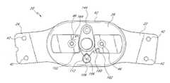
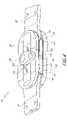
- FIG. 2is a perspective view of the lockable hinge of FIG. 1 taken from a posterior side of the hinge;
- FIG. 3is a perspective view of the lockable hinge of FIG. 1 taken from a posterior side of the hinge;
- FIG. 4is a perspective view of the lockable hinge of FIG. 1 taken from a posterior side of the hinge;
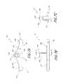
- FIG. 5is an exploded perspective view of the lockable hinge of FIG. 1 taken from a posterior side of the hinge;
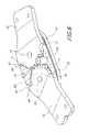
- FIG. 6is a perspective view of the lockable hinge of FIG. 1 , with the lateral hinge plate removed, taken from a posterior side of the hinge;
- FIG. 7Ais a side view of the flexion stop of the lockable hinge of FIG. 1 ;
- FIG. 7Bis a rear view of the flexion stop of FIG. 7A ;
- FIG. 7Cis a bottom cross-sectional view of the flexion stop of FIG. 7B , taken along line 7 C- 7 C;
- FIG. 8Ais a bottom view of the toggle of the lockable hinge of FIG. 1 ;
- FIG. 8Bis a rear view of the toggle of FIG. 8A ;
- FIG. 8Cis a side view of the toggle of FIG. 8A ;
- FIG. 8Dis a bottom cross-sectional view of the toggle of FIG. 8C , taken along line 8 D- 8 D.
- the present lockable hinge 20has a broad range of applications in orthopedic bracing.
- One such applicationis in a knee brace that assists people who suffer from musculo-skeletal or neurological disorders that compromise their ability to ambulate and/or stand.
- a doctormay recommend a knee brace including the present lockable hinge 20 for polio patients or patients who have suffered spinal cord injuries. Such patients may have difficulty controlling the muscle groups that are essential for walking and standing upright.
- a brace including the present lockable hinge 20enables the patient to walk and stand by reducing the patient's need to rely on certain muscles.
- the present lockable hinge 20will be described with reference to such a patient. Those of skill in the art will appreciate, however, that the present lockable hinge 20 is useful for a variety of other applications. Therefore, the description below should not be interpreted as limiting the present lockable hinge 20 to one application.
- the lockable hinge 20comprises a first arm 22 and a second arm 24 , each of which is pivotably secured between a first hinge plate 26 and a second hinge plate 28 .
- the first arm 22is pivotable at a first end 30 ( FIG. 5 ) about a first hinge axis 34 that is substantially perpendicular to the hinge plates 26 , 28 .
- the second arm 24is pivotable at a first end 32 about a second hinge axis 36 that is spaced from and substantially parallel to the first hinge axis 34 .
- the hinge 20includes a lateral bearing plate 38 situated between the arms 22 , 24 and the second hinge plate 28 , and a medial bearing plate 40 situated between the arms 22 , 24 and the first hinge plate 26 .
- the bearing plates 38 , 40are constructed of a low-friction material, such as nylon or Delrin®, that facilitates rotation of the arms 22 , 24 between the hinge plates 26 , 28 .
- a low-friction materialsuch as nylon or Delrin®
- the first arm 22corresponds to a first upright (not shown) that extends along the wearer's thigh
- the second arm 24corresponds to a second upright (not shown) that extends along the wearer's lower leg.
- Each arm 22 , 24preferably includes, near a second end spaced from the first end 30 , 32 , a pair of apertures 42 ( FIG. 1 ) that cooperate with fasteners to secure each arm 22 , 24 to its respective upright.
- the arms 22 , 24need not include the apertures 42 .
- each arm 22 , 24may extend along the wearer's leg and include apparatus for securing the arms 22 , 24 to the wearer's leg.
- Each arm 22 , 24includes, adjacent the first end 30 , 32 of each, a through-hole 44 ( FIGS. 5 and 6 ). Each through-hole 44 cooperates with a fastener 46 ( FIGS. 1 and 5 ) to pivotably secure the respective arm 22 , 24 to the hinge plates 26 , 28 .
- the fasteners 46comprise rivets.
- the fasteners 46could also comprise, for example, bolts, screws, or other similar fasteners.
- Each arm first end 30 , 32further comprises an extension abutment face 48 and a flexion abutment face 50 ( FIGS. 5 and 6 ).
- Each arm first end 30 , 32may further comprise a plurality of gear teeth 52 intermediate the abutment faces 48 , 50 .
- the gear teeth 52 on each arm 22 , 24preferably intermesh with the gear teeth 52 on the opposite arm 22 , 24 .
- the arms 22 , 24thus cannot rotate independently of one another, which results in smoother operation of the hinge 20 during knee flexion and extension.
- the gear teeth 52need not be provided, and that without the gear teeth 52 the arms 22 , 24 would be capable of rotating independently of one another.
- a portion of a lateral face 54 ( FIG. 5 ) of the first hinge plate 26 adjacent an anterior edge 56 thereofincludes a groove 58 .
- a ridge (not shown) on a medial face (not shown) of an extension stop 60 ( FIGS. 5 and 6 )rests in the groove and secures the extension stop 60 to the first hinge plate 26 .
- a portion of the medial face (not shown) of the second hinge plate 28 adjacent an anterior edge 62 ( FIG. 5 ) thereofalso includes a groove (not shown).
- a ridge 64 on a lateral face 66 ( FIG. 5 ) of the extension stop 60rests in the groove and secures the extension stop 60 to the second hinge plate 28 .
- the extension stop 60preferably includes a substantially straight anterior edge 68 corresponding to the anterior edge 56 of the first hinge plate 26 ( FIG. 5 ).
- a posterior edge 70 of the extension stop 60preferably includes first and second adjacent interior curved portions 72 , 74 that intersect at a crest 76 ( FIGS. 5 and 6 ).
- the first curved portion 72lies adjacent the first end 30 of the first arm 22
- the second curved portion 74lies adjacent the first end 32 of the second arm 24 .
- a radius of each curved portion 72 , 74is preferably slightly larger than an outer radius of the gear-toothed portions 52 of the first and second arms 22 , 24 .
- the curved portions 72 , 74thus provide clear rotation paths for the first ends 30 , 32 of the first and second arms 22 , 24 .
- the extension stop 60preferably includes at least one aperture 78 for receiving a fastener (not shown) such as a screw.
- the screwcooperates with a threaded hole 80 ( FIG. 5 ) in the first hinge plate 26 to secure the extension stop 60 to the first hinge plate 26 .
- the aperture 78is located adjacent the crest 76 .
- the aperture 78may be located anywhere on the extension stop 60 .
- the extension stop 60may include more than one aperture 78 , or may not include any aperture 78 .
- the extension stop 60may be glued to the first hinge plate 26 .
- the extension stop 60may also be secured to the second hinge plate 28 with mechanical fasteners or by gluing, for example.
- a superior end of the extension stop 60includes a first abutment face 82 ( FIG. 6 ) that is selectively engagable with the extension abutment face 48 on the first arm 22 to limit an extension range of the first arm 22 .
- an inferior end of the extension stop 60includes a second abutment face 84 that is selectively engagable with the extension abutment face 48 on the second arm 24 to limit an extension range of the second arm 24 .
- the extension stop 60limits extension of the hinge 20 to approximately 10°.
- a variety of other extension stopscould be provided to limit the hinge 20 to greater or lesser extension. For example, as a patient progresses through a prescribed course of treatment, he or she may be better able to extend his or her knee. Thus, at an advanced stage of the treatment, a physician may remove the extension stop and replace it with one allowing greater extension.
- the first hinge plate 26is substantially oval-shaped in side elevation aspect.
- the first hinge plate 26includes a pair of apertures 86 , 88 ( FIG. 5 ) corresponding to the first and second hinge axes 34 , 36 .
- the apertures 86 , 88preferably lie substantially along a longitudinal axis of the first hinge plate 26 , and are substantially evenly spaced from a midpoint of the first hinge plate 26 as measured along the longitudinal axis.
- the fasteners 46cooperate with these apertures 86 , 88 to secure the arms 22 , 24 to the first hinge plate 26 .
- a portion of the lateral face 54 of the first hinge plate 26 adjacent a posterior edge 90 thereofincludes a recess 92 for selectively housing a flexion stop 94 (FIGS. 5 and 7 A- 7 C).
- the flexion stop 94includes a substantially plate-like portion 95 ( FIGS. 7A and 7B ), having a thickness that is preferably substantially equal to a thickness of the arms 22 , 24 .
- a posterior edge 96 of the flexion stop 94is preferably substantially straight and lies adjacent the posterior edge 90 of the first hinge plate 26 (FIGS. 5 and 7 A- 7 C).
- An anterior edge 98 ( FIGS. 7A and 7C ) of the flexion stop 94preferably includes first and second adjacent interior curved portions 100 , 102 that intersect at a crest 104 ( FIG. 7A ).
- the first curved portion 100lies adjacent the gear teeth 52 on the first end 30 of the first arm 22 .
- the second curved portion 102lies adjacent the gear teeth 52 on the first end 32 of the second arm 24 .
- a radius of each curved portion 100 , 102is preferably slightly larger than an outer radius of the gear-toothed portions 52 of the first and second arms 22 , 24 .
- the curved portions 100 , 102thus provide clear rotation paths for the first ends 30 , 32 of the first and second arms 22 , 24 .
- a substantially cylindrical button 106protrudes from a lateral face 108 of the flexion stop 94 .
- a transverse cross-section of the button 106is not perfectly round. Rather, the cross-section is shaped substantially as a water droplet, including a rounded portion 110 and a crest 112 ( FIG. 7A ).
- the button 106could have a round cross-section, or any other geometric or irregular shape.
- the button 106preferably includes a substantially cylindrical hollow interior portion 114 ( FIG. 7C ). The button 106 enables a wearer to release the lockable hinge 20 from a locked configuration, as described below.
- a superior edge of the flexion stop 94which forms an angle of approximately 85° with the posterior edge 96 , comprises a first abutment face 116 ( FIG. 7A ) that is selectively engagable with the flexion abutment face 50 on the first arm 22 to limit a flexion range of the first arm 22 .
- an inferior edge of the flexion stop 94which forms an angle of approximately 85° with the posterior edge 96 , comprises a second abutment face 118 ( FIG. 7A ) that is selectively engagable with the flexion abutment face 50 on the second arm 24 to limit a flexion range of the second arm 24 .
- the flexion stop 94limits flexion of the hinge 20 to approximately 10°.
- Those of skill in the artwill appreciate that more or less flexion may be provided by altering the angle at which each flexion stop abutment face 116 , 118 intersects the flexion stop posterior edge 96 .
- a perimeter of the recess 92 in the lateral face 54 of the first hinge plate 26is preferably of substantially the same shape as, but slightly larger than, the perimeter of the flexion stop 94 ( FIG. 5 ).
- a depth of the recess 92is preferably slightly larger than the thickness of the flexion stop plate-like portion 95 .
- the recess 92is thus capable of housing the flexion stop plate-like portion 95 such that the plate-like portion 95 does not protrude above the lateral face 54 of the first hinge plate 26 , as shown in FIGS. 2 , 4 and 6 .
- a floor 120 of the recess 92includes a post 122 ( FIG. 5 ) that receives a medial end of coil spring 124 .
- a lateral end of the coil spring 124extends into the hollow interior portion 114 of the button 106 .
- the flexion stop 94is thus movable into and out of the recess 92 as the coil spring 124 recoils and expands around the post 122 .
- the coil spring 124biases the flexion stop 94 out of the recess 92 .
- the second hinge plate 28is substantially oval-shaped in side-elevation aspect ( FIG. 1 ).
- the second hinge plate 28includes first and second apertures 126 , 128 ( FIG. 5 ) corresponding to the first and second hinge axes 34 , 36 .
- the first and second apertures 126 , 128cooperate with the fasteners 46 to secure the second hinge plate 28 to the hinge 20 .
- the second hinge plate 28includes a fourth aperture 134 ( FIG. 5 ) that receives a fastener 136 such as a rivet.
- a toggle 138(FIGS. 5 and 8 A- 8 D) is pivotably mounted to the fastener 136 .
- the toggle 138is a substantially oblong switch having a first through hole 139 ( FIGS. 8C and 8D ) for receiving the fastener 136 .
- the toggle 138preferably has a substantially flat medial surface 140 ( FIGS. 8A , 8 C and 8 D) that abuts a lateral face 142 ( FIG. 5 ) of the second hinge plate 28 .
- the toggle 138is pivotable 360° about the fastener 136 .
- the togglemay be rotatable less than 360°.
- the toggle 138may also be mounted to the second hinge plate 28 in alternative fashions. For example, the toggle 138 may be slidable with respect to the second hinge plate 28 .
- a first end 144 ( FIGS. 8A , 8 C and 8 D) of the toggle 138engages the button 106 when the toggle 138 is rotated such that the first end 144 is adjacent the posterior edge of the second hinge plate 28 , as shown in FIG. 4 .
- the toggle 138retains the button 106 in a depressed position, which urges the plate-like portion 95 into the recess 92 .
- the flexion abutment faces 116 , 118 on the flexion stop 94do not interfere with the flexion abutment faces 50 on the arms 22 , 24 .
- the arms 22 , 24are thus free to rotate between a maximum extension, wherein the extension abutment faces 82 , 84 ( FIG. 6 ) on the extension stop 60 abut the extension abutment faces 48 on the arms 22 , 24 , and a maximum flexion, wherein the flexion abutment faces 50 ( FIG. 6 ) on the arms 22 , 24 abut the button 106 .
- This configurationdefines a free range of motion for the hinge 20 .
- the free range of motion of the hinge 20is between 10° short of full extension and 125° of flexion.
- the hingecould have a free range of motion between a variety of different extension and flexion limits.
- the button 106always protrudes above the lateral face 142 ( FIGS. 2 and 3 ) of the second hinge plate 28 unless the wearer manually depresses the button 106 .
- the button 106thus prevents the hinge 20 from accidentally entering the free range of motion mode. If the toggle 138 were to accidentally rotate such that the first end 144 approached the button 106 , the toggle 138 would contact a side of the button 106 . The toggle 138 could not ride over the button 106 and place the hinge in the free range of motion mode.
- the medial surface 140 of the toggle 138preferably includes a depression 146 ( FIGS. 8B , 8 C and 8 D) that is substantially the same size and shape as a cross-section of the button 106 .
- a short length of the lateral end 148 ( FIGS. 2 and 7B ) of the button 106is disposed within the depression 146 . The button 106 thus locks the toggle 138 in this position.
- the toggle 138Adjacent the first end 144 , the toggle 138 preferably includes a second through-hole 150 ( FIGS. 8B , 8 C and 8 D) that is substantially centered on the depression 146 , but has a shorter perimeter to prevent the button from entering the second through-hole 150 .
- a slender objectsuch as a straightened paper clip or the point of a pen
- the perimeter of the second through-hole 150is short enough that objects cannot accidentally enter the second through-hole 150 and depress the button 106 , which might accidentally unlock the toggle 138 from the free range of motion position of FIG. 4 .
- the lateral end 148 ( FIGS. 7A and 7C ) of the button 106preferably includes an indentation 151 near a center thereof.
- the indentation 151guides the object that the wearer inserts and enable smooth operation of the button 106 by reducing a tendency for the object to slide across the button 106 as the wearer applies a pushing force.
- the indentation 151need not be provided.
- the flexion stop 94may include a second button (not shown) protruding from the plate-like portion 95 in substantially the same direction as the button 106 and spaced from the button 106 .
- the second buttonwould preferably extend above the surface of the second hinge plate 28 , but would preferably not engage the toggle 138 .
- the wearerwould depress the second button and hold it down while rotating the toggle 138 . While engaging the toggle 138 with the button 106 , the wearer's finger would not interfere with the toggle 138 . While disengaging the toggle 138 from the button 106 , the wearer would not need to use a separate tool to depress the button 106 .
- the second buttonwould not interfere with rotation of the arms 22 , 24 .
- the second buttoncould be positioned posteriorly of the button 106 . If the second button were positioned superiorly of the button 106 , the arm 22 could include a slot (not shown) for receiving the second button as the arm 22 rotated.
- the spring 124urges the flexion stop 94 out of the recess 92 .
- the arms 22 , 24are at any angle of flexion greater than 10°, a medial surface of each arm 22 , 24 maintains the flexion stop 94 within the recess 92 as shown in FIG. 2 .
- the arms 22 , 24are thus freely rotatable between maximum flexion and 10° short of full extension.
- the flexion abutment faces 50 on the armsclear the flexion abutment faces 116 , 118 on the flexion stop 94 , as shown in FIG. 3 .
- the medial surfaces of the arms 22 , 24no longer maintain the flexion stop 94 within the recess 92 .
- the spring 124forces the flexion stop 94 out of the recess 92 until the lateral face 108 of the flexion stop 94 contacts a medial surface of the lateral bearing plate 38 , as shown in FIG. 3 . If a lateral bearing plate 38 is not provided, then the spring 124 forces the flexion stop 94 out of the recess 92 until the lateral face 108 of the flexion stop 94 contacts a medial surface of the second hinge plate 28 .
- a second end 152 ( FIGS. 8A and 8D ) of the toggle 138 opposite the first end 144includes an extension 154 having a V-shaped indentation 156 ( FIG. 8C ).
- the toggle 138is oriented such that the toggle first end 144 is adjacent the anterior edge 62 of the second hinge plate 28 ( FIG. 1 ). In this orientation, the crest 112 of the button 106 resides in the V-shaped indentation 156 on the second end 152 of the toggle 138 , as shown in FIG. 1 .
- the button 106thus prevents the toggle 138 from rotating freely.
- the flexion stop 94limits flexion of the arms 22 , 24 to 10°.
- the hinge 20thus provides support for the wearer's knee, preventing him or her from flexing his or her knee more than 10°.
- the hinge 20thus provides the benefits described above to patients with musculo-skeletal or neurological disorders.
- the patientis ready to flex his or her knee, for example to sit down, he or she depresses the button 106 until the flexion stop 94 no longer interferes with the arms 22 , 24 . While holding the button 106 down, the patient is able to flex his or her knee.
- the patientwishes to lock the hinge 20 in the free range of motion mode of FIG. 4 , he or she completely depresses the button 106 until the lateral end 148 ( FIG. 7B ) of the button 106 is substantially flush with the lateral face 142 of the second hinge plate 28 . While holding the button 106 down, the patient rotates the toggle 138 into the locked position shown in FIG. 4 . The button 106 lateral face pops up into the depression 146 on the toggle 138 , locking the hinge 20 in the free range of motion mode. To disengage the button 106 from the toggle 138 , the patient follows the procedure described above.
- a perimeter of the lateral end 148 of the button 106may include a chamfer 158 ( FIGS. 7B and 7C ).
- an edge of the toggle adjacent the depressionmay include a sloped surface 159 ( FIGS. 8A , 8 B and 8 C).
- the sloped surface 159engages the chamfer 158 and urges the button 106 toward the lateral face 142 of the second hinge plate 28 .
- the wearerneed not maintain the button lateral end 148 completely flush with the lateral face 142 of the second hinge plate 28 . The wearer is thus able to lock the hinge 20 more easily.
- Those of skill in the artwill appreciate that neither the chamfer 158 nor the sloped surface 159 is necessary to the proper functioning of the hinge 20 .
- a perimeter of the toggle 138may include a pointer 160 ( FIG. 8C ), comprising a crest-shaped protrusion.
- the lateral face 142 of the second hinge plate 28may include a locked symbol 162 and an unlocked symbol 164 ( FIG. 1 ).
- the toggle first end 144is positioned 180° from the button 106 and the hinge 20 is in the lockable mode
- the pointer 160is positioned next to the locked symbol 162 , indicating to the wearer that the hinge 20 is in the locked mode.
- the locked and unlocked symbols 162 , 164 and the pointer 160are not necessary to the proper functioning of the hinge 20 .
- a knee brace including the present hinge 20combines the support of a knee-immobilizing brace with the mobility of a fully flexible brace.
- a person suffering from any instability of the kneecan wear the brace to assist him or her in standing and walking.
- He or sheneed not remove the brace in order to bend his or her knee. He or she simply depresses the button 106 while bending his or her knee. If the person wishes to lock the hinge in the free range of motion mode, for example, to participate in physical therapy, he or she depresses the button 106 and rotates the toggle 138 until it covers the button 106 .
- the personWhen the person is ready to convert the hinge back to the locked mode, he or she inserts a slender object into the through-hole 150 , depresses the button 106 and turns the toggle 138 until it no longer covers the button 106 .
- the personrotates the toggle 138 to the position illustrated in FIGS. 1 , 2 and 3 such that the button 106 engages the V-shaped indentation 156 .
- the button 106thus prevents the toggle 138 from rotating freely.
- the personrotates the arms 22 , 24 such that the arms 22 , 24 do not maintain the flexion stop 94 within the recess 92 .
- the flexion stop 94pops out of the recess, and the hinge 20 is in the locked mode.
- the bracethus provide support for standing and ambulation.
Landscapes
- Health & Medical Sciences (AREA)
- Nursing (AREA)
- Orthopedic Medicine & Surgery (AREA)
- Engineering & Computer Science (AREA)
- Biomedical Technology (AREA)
- Heart & Thoracic Surgery (AREA)
- Vascular Medicine (AREA)
- Life Sciences & Earth Sciences (AREA)
- Animal Behavior & Ethology (AREA)
- General Health & Medical Sciences (AREA)
- Public Health (AREA)
- Veterinary Medicine (AREA)
- Orthopedics, Nursing, And Contraception (AREA)
- Prostheses (AREA)
- Rehabilitation Tools (AREA)
Abstract
Description
Claims (9)
Priority Applications (1)
| Application Number | Priority Date | Filing Date | Title |
|---|---|---|---|
| US11/768,868US7722555B2 (en) | 2002-09-11 | 2007-06-26 | Lockable hinge |
Applications Claiming Priority (2)
| Application Number | Priority Date | Filing Date | Title |
|---|---|---|---|
| US10/242,372US7235058B2 (en) | 2002-09-11 | 2002-09-11 | Lockable hinge |
| US11/768,868US7722555B2 (en) | 2002-09-11 | 2007-06-26 | Lockable hinge |
Related Parent Applications (1)
| Application Number | Title | Priority Date | Filing Date |
|---|---|---|---|
| US10/242,372ContinuationUS7235058B2 (en) | 2002-09-11 | 2002-09-11 | Lockable hinge |
Publications (2)
| Publication Number | Publication Date |
|---|---|
| US20080077065A1 US20080077065A1 (en) | 2008-03-27 |
| US7722555B2true US7722555B2 (en) | 2010-05-25 |
Family
ID=31991395
Family Applications (2)
| Application Number | Title | Priority Date | Filing Date |
|---|---|---|---|
| US10/242,372Expired - LifetimeUS7235058B2 (en) | 2002-09-11 | 2002-09-11 | Lockable hinge |
| US11/768,868Expired - LifetimeUS7722555B2 (en) | 2002-09-11 | 2007-06-26 | Lockable hinge |
Family Applications Before (1)
| Application Number | Title | Priority Date | Filing Date |
|---|---|---|---|
| US10/242,372Expired - LifetimeUS7235058B2 (en) | 2002-09-11 | 2002-09-11 | Lockable hinge |
Country Status (6)
| Country | Link |
|---|---|
| US (2) | US7235058B2 (en) |
| EP (1) | EP1549266A2 (en) |
| JP (1) | JP2005537887A (en) |
| AU (1) | AU2003259806A1 (en) |
| CA (1) | CA2497023A1 (en) |
| WO (1) | WO2004024040A2 (en) |
Cited By (20)
| Publication number | Priority date | Publication date | Assignee | Title |
|---|---|---|---|---|
| US9125730B2 (en) | 2011-10-31 | 2015-09-08 | Ossur Hf | Orthopedic device for dynamically treating the knee |
| US9220624B2 (en) | 2010-09-16 | 2015-12-29 | Ossur Hf | Posterior cruciate ligament support brace |
| US9351864B2 (en) | 2013-01-25 | 2016-05-31 | Ossur Hf | Orthopedic device having a dynamic control system |
| US9539135B2 (en) | 2013-01-25 | 2017-01-10 | Ossur Hf | Orthopedic device having a dynamic control system and method for using the same |
| US9597786B2 (en) | 2013-08-22 | 2017-03-21 | Ossur Hf | Torque limiting tool and method for using the same |
| US9662261B2 (en) | 2013-01-16 | 2017-05-30 | Ekso Bionics, Inc. | Fail-safe system for exoskeleton joints |
| US9668903B2 (en) | 2014-11-20 | 2017-06-06 | Ossur Iceland Ehf | Polymeric polycentric hinge |
| USD813089S1 (en) | 2016-11-08 | 2018-03-20 | Ossur Iceland Ehf | D-ring |
| US9925082B2 (en) | 2012-03-20 | 2018-03-27 | Ossur Hf | Orthopedic device |
| USD835289S1 (en) | 2016-11-08 | 2018-12-04 | Ossur Iceland Ehf | Orthopedic device |
| US10143581B2 (en) | 2013-06-21 | 2018-12-04 | Ossur Hf | Dynamic tension system for orthopedic device |
| US10342723B2 (en) | 2015-04-06 | 2019-07-09 | Ekso Bionics, Inc. | Exoskeleton cord loop-type actuator |
| US10413437B2 (en) | 2013-01-25 | 2019-09-17 | Ossur Iceland Ehf | Orthopedic device having a dynamic control system and method for using the same |
| US10427023B2 (en)* | 2016-04-15 | 2019-10-01 | Bsn Sports, Llc | Shoulder pads and method of manufacturing the same |
| US10512305B2 (en) | 2014-07-11 | 2019-12-24 | Ossur Hf | Tightening system with a tension control mechanism |
| US10617549B2 (en) | 2016-04-04 | 2020-04-14 | Ossur Iceland Ehf | Orthopedic device |
| US10653546B2 (en) | 2014-10-31 | 2020-05-19 | Ossur Hf | Orthopedic device having a dynamic control system |
| WO2020198489A1 (en)* | 2019-03-26 | 2020-10-01 | Ossur Iceland Ehf | Hinge assembly for an orthopedic device |
| US11096803B2 (en) | 2016-12-06 | 2021-08-24 | Ossur Iceland Ehf | Movable joint for use in a prosthetic or orthopedic system |
| US11547590B2 (en) | 2017-11-27 | 2023-01-10 | Ossur Iceland Ehf | Orthopedic device having a suspension element |
Families Citing this family (34)
| Publication number | Priority date | Publication date | Assignee | Title |
|---|---|---|---|---|
| ITVR20030027A1 (en)* | 2003-03-06 | 2004-09-07 | Fgp Srl | JOINT FOR ADJUSTABLE ANGULAR EXCURSION KNEE. |
| DE10311189B4 (en)* | 2003-03-12 | 2007-02-22 | Otto Bock Healthcare Gmbh | Orthopedic technical aid with a locking device |
| US7811242B2 (en) | 2004-06-24 | 2010-10-12 | Djo, Llc | Motion controlling hinge for orthopedic brace |
| US7507215B2 (en) | 2005-07-08 | 2009-03-24 | Jri Development Group, Llc | Orthotic brace |
| DE102006021789A1 (en) | 2006-05-09 | 2007-11-22 | Otto Bock Healthcare Ip Gmbh & Co. Kg | joint orthosis |
| US7544174B2 (en) | 2006-09-29 | 2009-06-09 | Djo, Llc | Quiet flexion/extension stop for orthopedic brace and orthopedic brace incorporating a quiet flexion/extension stop |
| US8083701B2 (en)* | 2007-06-25 | 2011-12-27 | OTS Corporation | Multi-centric orthopedic hinge joint |
| KR100834074B1 (en)* | 2008-01-11 | 2008-06-02 | 다빈치메디텍주식회사 | Knee Joint Orthosis |
| US9033907B2 (en)* | 2009-03-30 | 2015-05-19 | Aaron Matthew Noble | Adjustable hinge |
| US8728018B2 (en)* | 2009-03-31 | 2014-05-20 | Top Shelf Manufacturing, Llc | Post operative hinge brace |
| KR101118559B1 (en) | 2010-02-12 | 2012-02-24 | 경희대학교 산학협력단 | Articulating brace |
| US9788988B2 (en) | 2010-09-08 | 2017-10-17 | Ossur Hf | Hinge for orthopedic devices |
| ITVR20110122A1 (en) | 2011-05-30 | 2012-12-01 | Fgp Srl | JOINT FOR ORTHOPEDIC TUTOR WITH LOCKING SYSTEM AND QUICK RELEASE |
| WO2013181366A1 (en) | 2012-05-31 | 2013-12-05 | Ossur Hf | Hinge for an orthopedic device |
| US20140005584A1 (en)* | 2012-07-02 | 2014-01-02 | Ryan Russell Pretz | Knee brace with expansible pressure components |
| EP2931204B1 (en) | 2012-12-11 | 2019-04-03 | Ekso Bionics, Inc. | Reconfigurable exoskeleton |
| ITRM20130100A1 (en)* | 2013-02-21 | 2014-08-22 | Tecnoway S A S | TUTOR FOR JOINT. |
| WO2015123259A1 (en) | 2014-02-11 | 2015-08-20 | Ossur Hf | Hinge for an orthopedic device |
| EP2921145A1 (en) | 2014-03-22 | 2015-09-23 | MDH Sp. z o.o. | Orthosis with four-axial mechanism stabilizing, especially knee joint orthosis |
| KR101522964B1 (en)* | 2015-02-04 | 2015-05-27 | 주식회사 제이원메딕스 | Braces for relief knee osteoarthritis |
| US11395753B2 (en) | 2015-06-12 | 2022-07-26 | Becker Orthopedic Appliance Company | Orthotic joint devices, joint device components, and methods |
| US10500081B2 (en)* | 2015-06-12 | 2019-12-10 | Becker Orthopedic Appliance Company | Triple action orthotic ankle joint and methods |
| DE102015114540B4 (en)* | 2015-08-31 | 2020-02-27 | Ottobock Se & Co. Kgaa | Locking hinge |
| DE102015217205A1 (en)* | 2015-09-09 | 2017-03-09 | Bauerfeind Ag | Schwenklimitierbares biaxial joint |
| EP3463207B1 (en)* | 2016-05-31 | 2022-04-20 | United Surgical, Inc. | Flexion and extension range limiting hinge for an orthopedic brace |
| DE102016114834A1 (en)* | 2016-08-10 | 2018-02-15 | Otto Bock Healthcare Gmbh | Joint for an orthopedic device |
| US10117769B2 (en) | 2016-08-31 | 2018-11-06 | Jay C. Humphrey | Orthopedic knee brace |
| AU2018206399B2 (en) | 2017-01-06 | 2020-01-02 | Djo, Llc | Orthosis, related components and methods of use |
| CA3079503A1 (en)* | 2017-11-07 | 2019-05-16 | Djo, Llc | Brace having integrated remote patient monitoring technology and method of using same |
| USD846130S1 (en)* | 2018-01-31 | 2019-04-16 | Ortho Systems | Knee brace |
| WO2020123583A1 (en) | 2018-12-11 | 2020-06-18 | Ossur Iceland Ehf | Hinge having a rotation-stop lock |
| US11607330B1 (en) | 2019-01-21 | 2023-03-21 | Medical Specialties, Inc. | Orthopedic and orthotic brace and hinge assembly with custom-selectable range-controlling hinge stops |
| CN111419652B (en)* | 2020-06-12 | 2020-09-29 | 上海傅利叶智能科技有限公司 | Power-source-free knee joint mechanism |
| WO2024006311A1 (en)* | 2022-06-29 | 2024-01-04 | Ossur Iceland Ehf | Polymeric polycentric hinge |
Citations (58)
| Publication number | Priority date | Publication date | Assignee | Title |
|---|---|---|---|---|
| US401933A (en) | 1889-04-23 | Fracture apparatus | ||
| US2832334A (en) | 1956-05-23 | 1958-04-29 | Stephen H Whitelaw | Therapeutic device for use in manipulative treatment of joints of the human body |
| US3826251A (en) | 1973-01-04 | 1974-07-30 | C Ross | Locking knee joint for orthopedic leg brace |
| US3898709A (en) | 1974-09-26 | 1975-08-12 | Surgical Appliance Ind | Hinge for knee brace |
| US4088130A (en) | 1977-05-16 | 1978-05-09 | Surgical Appliance Industries, Inc. | Hinge for knee brace |
| US4337764A (en) | 1981-03-02 | 1982-07-06 | United States Manufacturing Company | Adjustable motion brace |
| US4340041A (en) | 1979-01-24 | 1982-07-20 | Blanc Gmbh & Co. | Articulate splint for surgical purposes |
| US4353361A (en) | 1980-08-25 | 1982-10-12 | Foster Robert W | Orthotic/prosthetic joint |
| US4463751A (en) | 1982-12-27 | 1984-08-07 | Bledsoe Gary R | Stabilizing knee hinge |
| US4489718A (en) | 1983-03-08 | 1984-12-25 | Medical Designs, Inc. | Knee brace hinge |
| US4520804A (en) | 1981-08-04 | 1985-06-04 | Digeorge Michael A | Double-locking ratchet for orthopedic brace |
| US4524764A (en) | 1983-09-06 | 1985-06-25 | Miller Harold E | Knee brace |
| US4554913A (en) | 1983-11-07 | 1985-11-26 | Scott Orthopedics, Inc. | Adjustable joint for a knee brace |
| USD286183S (en) | 1984-06-04 | 1986-10-14 | Scott Orthopedics, Inc. | Adjustable joint for a knee brace |
| US4681097A (en) | 1986-01-23 | 1987-07-21 | Pansiera Timothy T | Orthopedic brace |
| US4732143A (en) | 1987-02-13 | 1988-03-22 | Spectrum Orthopedics, Ltd. | Selectable extension stop for a polycentric hinge |
| US4777941A (en) | 1987-07-29 | 1988-10-18 | Borig Donald A | Orthopedic knee prosthesis and hinge |
| US4817588A (en)* | 1987-07-01 | 1989-04-04 | Medical Technology, Inc. | Motion restraining knee brace |
| US4915098A (en)* | 1985-04-18 | 1990-04-10 | Protectair Limited | Orthopaedic hinge mechanism |
| US4982732A (en) | 1990-02-06 | 1991-01-08 | Orthopedic Technology, Inc. | Orthopedic rehabilitation knee brace |
| GB2235012A (en) | 1989-08-09 | 1991-02-20 | Sec Dep For Health | Orthotic device |
| US5039247A (en) | 1988-10-26 | 1991-08-13 | Protectair Limited | Adjustable hinge device |
| US5042464A (en) | 1985-10-04 | 1991-08-27 | Minnesota Mining And Manufacturing Company | Off-the shelf custom knee brace |
| US5062858A (en) | 1989-05-30 | 1991-11-05 | Vanden Broeck | Connecting device for two members of an artificial joint |
| US5063917A (en) | 1989-08-14 | 1991-11-12 | Protectair Limited | Limb brace or immobilizer |
| US5078127A (en) | 1991-02-06 | 1992-01-07 | Orthopedic Technology, Inc. | Knee brace with articulating brace hinge axis |
| US5107824A (en) | 1989-09-14 | 1992-04-28 | Anodyne, Inc. | Anatomically correct knee brace hinge |
| US5292303A (en) | 1992-07-01 | 1994-03-08 | Smith & Nephew Donjoy, Inc. | Hinged orthopedic brace having an adjustable pivot range |
| US5328446A (en) | 1992-10-29 | 1994-07-12 | Becker Orthopedic Appliance Company | Orthopedic joint and method for treating a contracture |
| EP0611093A2 (en) | 1993-02-05 | 1994-08-17 | Stephen Hutchins | Knee brace |
| EP0466538B1 (en) | 1990-07-10 | 1995-02-15 | ETABLISSEMENTS PROTEOR Société anonyme dite: | Joint for lower limbs orthosis, lockable in the stretched position of these limbs |
| US5399154A (en) | 1993-06-30 | 1995-03-21 | Empi, Inc. | Constant torque range-of-motion splint |
| US5399149A (en) | 1993-08-05 | 1995-03-21 | Frankowiak; Ray M. | Knee hinge with selectively limited motion |
| US5409449A (en) | 1993-07-09 | 1995-04-25 | Smith & Nephew Donjoy Inc. | Detent mechanism for a hinged orthopedic brace |
| US5443444A (en) | 1994-07-19 | 1995-08-22 | Professional Care Products Incorporated | Orthopaedic polycentric hinge |
| EP0761186A2 (en) | 1995-08-30 | 1997-03-12 | David Ernest Young | Improved true bi-pivotal orthopaedic and orthotic hinge with incremental motion control |
| US5630791A (en) | 1995-04-03 | 1997-05-20 | Glynn Orthopedics Services, Inc. | Orthotic joint |
| US5676640A (en) | 1995-04-07 | 1997-10-14 | Biedermann Motech Gmbh | Orthesis joint system |
| EP0832624A2 (en) | 1996-09-25 | 1998-04-01 | Johnson & Johnson Medical Limited | Hinge with movement limitation |
| US5749840A (en) | 1989-12-07 | 1998-05-12 | Ultraflex Systems, Inc. | Dynamic splint |
| US5772618A (en)* | 1996-05-31 | 1998-06-30 | Breg, Inc. | Hinge for an orthopedic brace |
| US5814000A (en) | 1996-07-12 | 1998-09-29 | Professional Products, Inc. | Adjustable joint brace |
| GB2326098A (en) | 1997-06-09 | 1998-12-16 | Davis Designs Ltd | Lockable knee brace |
| EP0538695B1 (en) | 1991-10-15 | 1998-12-16 | Smith & Nephew, Inc. | Multiple fixed angle orthopaedic appliance |
| US5885235A (en) | 1996-02-19 | 1999-03-23 | Albrecht Gmbh | Joint brace and more particularly a knee brace |
| US5921946A (en) | 1997-10-22 | 1999-07-13 | Smith & Nephew, Inc. | Joint brace hinges |
| WO1999042071A1 (en) | 1996-08-14 | 1999-08-26 | Orthotic Consultants Asia Pacific Pty. Limited | Joint extension assist hinge mechanism |
| USD416624S (en) | 1998-10-23 | 1999-11-16 | Nauert Richard S | Knee brace |
| US5997493A (en) | 1996-09-25 | 1999-12-07 | Johnson & Johnsonprofessional, Inc. | "Hinge with movement limitation" |
| US6039709A (en) | 1998-12-16 | 2000-03-21 | Orthosis Corrective Systems | Orthopedic hinge assembly |
| US6080122A (en) | 1998-08-24 | 2000-06-27 | Gulledge; Ronald E. | Motion restraining brace |
| WO2001010360A1 (en) | 1999-08-10 | 2001-02-15 | Nauert Richard S | Knee brace operating hinge |
| USRE37209E1 (en)* | 1988-10-21 | 2001-06-05 | David Ellis Hensley | Extension deceleration orthosis |
| WO2001070149A1 (en) | 2000-03-23 | 2001-09-27 | Bandage- En Corsetindustrie Basko B.V. | Gravity operated locking hinge |
| WO2002002037A1 (en) | 2000-06-30 | 2002-01-10 | Dj Orthopedics, Llc | Orthopaedic brace having an axially settable range of motion hinge |
| US6375632B1 (en) | 1998-05-15 | 2002-04-23 | Albrecht Gmbh | Joint support with a gear wheel adjustment mechanism for the stepless fine adjustment of a pivot range limit |
| US6387066B1 (en) | 2000-10-10 | 2002-05-14 | Joseph Whiteside | Self-aligning adjustable orthopedic joint brace |
| US6527733B1 (en)* | 2000-02-22 | 2003-03-04 | Dj Orthopedics, Llc | Hinge assembly for an orthopedic knee brace and knee brace incorporating the hinge assembly |
Family Cites Families (1)
| Publication number | Priority date | Publication date | Assignee | Title |
|---|---|---|---|---|
| US3826334A (en)* | 1972-07-07 | 1974-07-30 | R Spillman | Mobile aerial platform |
- 2002
- 2002-09-11USUS10/242,372patent/US7235058B2/ennot_activeExpired - Lifetime
- 2003
- 2003-08-14WOPCT/US2003/025309patent/WO2004024040A2/ennot_activeApplication Discontinuation
- 2003-08-14EPEP03795607Apatent/EP1549266A2/ennot_activeWithdrawn
- 2003-08-14AUAU2003259806Apatent/AU2003259806A1/ennot_activeAbandoned
- 2003-08-14CACA002497023Apatent/CA2497023A1/ennot_activeAbandoned
- 2003-08-14JPJP2004536027Apatent/JP2005537887A/enactivePending
- 2007
- 2007-06-26USUS11/768,868patent/US7722555B2/ennot_activeExpired - Lifetime
Patent Citations (63)
| Publication number | Priority date | Publication date | Assignee | Title |
|---|---|---|---|---|
| US401933A (en) | 1889-04-23 | Fracture apparatus | ||
| US2832334A (en) | 1956-05-23 | 1958-04-29 | Stephen H Whitelaw | Therapeutic device for use in manipulative treatment of joints of the human body |
| US3826251A (en) | 1973-01-04 | 1974-07-30 | C Ross | Locking knee joint for orthopedic leg brace |
| US3898709A (en) | 1974-09-26 | 1975-08-12 | Surgical Appliance Ind | Hinge for knee brace |
| US4088130A (en) | 1977-05-16 | 1978-05-09 | Surgical Appliance Industries, Inc. | Hinge for knee brace |
| US4340041A (en) | 1979-01-24 | 1982-07-20 | Blanc Gmbh & Co. | Articulate splint for surgical purposes |
| US4353361A (en) | 1980-08-25 | 1982-10-12 | Foster Robert W | Orthotic/prosthetic joint |
| US4337764A (en) | 1981-03-02 | 1982-07-06 | United States Manufacturing Company | Adjustable motion brace |
| US4520804A (en) | 1981-08-04 | 1985-06-04 | Digeorge Michael A | Double-locking ratchet for orthopedic brace |
| US4463751A (en) | 1982-12-27 | 1984-08-07 | Bledsoe Gary R | Stabilizing knee hinge |
| US4489718A (en) | 1983-03-08 | 1984-12-25 | Medical Designs, Inc. | Knee brace hinge |
| US4524764A (en) | 1983-09-06 | 1985-06-25 | Miller Harold E | Knee brace |
| US4554913A (en) | 1983-11-07 | 1985-11-26 | Scott Orthopedics, Inc. | Adjustable joint for a knee brace |
| USD286183S (en) | 1984-06-04 | 1986-10-14 | Scott Orthopedics, Inc. | Adjustable joint for a knee brace |
| US4915098A (en)* | 1985-04-18 | 1990-04-10 | Protectair Limited | Orthopaedic hinge mechanism |
| US5042464A (en) | 1985-10-04 | 1991-08-27 | Minnesota Mining And Manufacturing Company | Off-the shelf custom knee brace |
| US4681097A (en) | 1986-01-23 | 1987-07-21 | Pansiera Timothy T | Orthopedic brace |
| US4732143A (en) | 1987-02-13 | 1988-03-22 | Spectrum Orthopedics, Ltd. | Selectable extension stop for a polycentric hinge |
| US4817588A (en)* | 1987-07-01 | 1989-04-04 | Medical Technology, Inc. | Motion restraining knee brace |
| US4777941A (en) | 1987-07-29 | 1988-10-18 | Borig Donald A | Orthopedic knee prosthesis and hinge |
| USRE37209E1 (en)* | 1988-10-21 | 2001-06-05 | David Ellis Hensley | Extension deceleration orthosis |
| US5039247A (en) | 1988-10-26 | 1991-08-13 | Protectair Limited | Adjustable hinge device |
| US5062858A (en) | 1989-05-30 | 1991-11-05 | Vanden Broeck | Connecting device for two members of an artificial joint |
| GB2235012A (en) | 1989-08-09 | 1991-02-20 | Sec Dep For Health | Orthotic device |
| US5063917A (en) | 1989-08-14 | 1991-11-12 | Protectair Limited | Limb brace or immobilizer |
| US5107824A (en) | 1989-09-14 | 1992-04-28 | Anodyne, Inc. | Anatomically correct knee brace hinge |
| US5749840A (en) | 1989-12-07 | 1998-05-12 | Ultraflex Systems, Inc. | Dynamic splint |
| US4982732A (en) | 1990-02-06 | 1991-01-08 | Orthopedic Technology, Inc. | Orthopedic rehabilitation knee brace |
| EP0466538B1 (en) | 1990-07-10 | 1995-02-15 | ETABLISSEMENTS PROTEOR Société anonyme dite: | Joint for lower limbs orthosis, lockable in the stretched position of these limbs |
| US5078127A (en) | 1991-02-06 | 1992-01-07 | Orthopedic Technology, Inc. | Knee brace with articulating brace hinge axis |
| EP0538695B1 (en) | 1991-10-15 | 1998-12-16 | Smith & Nephew, Inc. | Multiple fixed angle orthopaedic appliance |
| US5292303A (en) | 1992-07-01 | 1994-03-08 | Smith & Nephew Donjoy, Inc. | Hinged orthopedic brace having an adjustable pivot range |
| US5328446A (en) | 1992-10-29 | 1994-07-12 | Becker Orthopedic Appliance Company | Orthopedic joint and method for treating a contracture |
| EP0611093A2 (en) | 1993-02-05 | 1994-08-17 | Stephen Hutchins | Knee brace |
| US5419754A (en) | 1993-02-05 | 1995-05-30 | Robert Johnson | Knee brace |
| EP0611093A3 (en) | 1993-02-05 | 1994-08-31 | Stephen Hutchins | Knee brace |
| US5399154A (en) | 1993-06-30 | 1995-03-21 | Empi, Inc. | Constant torque range-of-motion splint |
| EP0633007B1 (en) | 1993-07-09 | 1997-10-22 | Smith & Nephew, Inc. | Detent mechanism for hinged orthopedic brace |
| US5409449A (en) | 1993-07-09 | 1995-04-25 | Smith & Nephew Donjoy Inc. | Detent mechanism for a hinged orthopedic brace |
| US5399149A (en) | 1993-08-05 | 1995-03-21 | Frankowiak; Ray M. | Knee hinge with selectively limited motion |
| US5443444A (en) | 1994-07-19 | 1995-08-22 | Professional Care Products Incorporated | Orthopaedic polycentric hinge |
| US5630791A (en) | 1995-04-03 | 1997-05-20 | Glynn Orthopedics Services, Inc. | Orthotic joint |
| US5676640A (en) | 1995-04-07 | 1997-10-14 | Biedermann Motech Gmbh | Orthesis joint system |
| EP0761186A2 (en) | 1995-08-30 | 1997-03-12 | David Ernest Young | Improved true bi-pivotal orthopaedic and orthotic hinge with incremental motion control |
| US5885235A (en) | 1996-02-19 | 1999-03-23 | Albrecht Gmbh | Joint brace and more particularly a knee brace |
| US5772618A (en)* | 1996-05-31 | 1998-06-30 | Breg, Inc. | Hinge for an orthopedic brace |
| US5814000A (en) | 1996-07-12 | 1998-09-29 | Professional Products, Inc. | Adjustable joint brace |
| WO1999042071A1 (en) | 1996-08-14 | 1999-08-26 | Orthotic Consultants Asia Pacific Pty. Limited | Joint extension assist hinge mechanism |
| EP0832624A2 (en) | 1996-09-25 | 1998-04-01 | Johnson & Johnson Medical Limited | Hinge with movement limitation |
| US6004283A (en) | 1996-09-25 | 1999-12-21 | Johnson & Johnson Professional, Inc. | Hinge with locking means |
| US5997493A (en) | 1996-09-25 | 1999-12-07 | Johnson & Johnsonprofessional, Inc. | "Hinge with movement limitation" |
| GB2326098A (en) | 1997-06-09 | 1998-12-16 | Davis Designs Ltd | Lockable knee brace |
| US5921946A (en) | 1997-10-22 | 1999-07-13 | Smith & Nephew, Inc. | Joint brace hinges |
| US6375632B1 (en) | 1998-05-15 | 2002-04-23 | Albrecht Gmbh | Joint support with a gear wheel adjustment mechanism for the stepless fine adjustment of a pivot range limit |
| US6080122A (en) | 1998-08-24 | 2000-06-27 | Gulledge; Ronald E. | Motion restraining brace |
| USD416624S (en) | 1998-10-23 | 1999-11-16 | Nauert Richard S | Knee brace |
| US6039709A (en) | 1998-12-16 | 2000-03-21 | Orthosis Corrective Systems | Orthopedic hinge assembly |
| WO2001010360A1 (en) | 1999-08-10 | 2001-02-15 | Nauert Richard S | Knee brace operating hinge |
| US6402711B1 (en)* | 1999-08-10 | 2002-06-11 | Richard S. Nauert | Knee brace operating hinge |
| US6527733B1 (en)* | 2000-02-22 | 2003-03-04 | Dj Orthopedics, Llc | Hinge assembly for an orthopedic knee brace and knee brace incorporating the hinge assembly |
| WO2001070149A1 (en) | 2000-03-23 | 2001-09-27 | Bandage- En Corsetindustrie Basko B.V. | Gravity operated locking hinge |
| WO2002002037A1 (en) | 2000-06-30 | 2002-01-10 | Dj Orthopedics, Llc | Orthopaedic brace having an axially settable range of motion hinge |
| US6387066B1 (en) | 2000-10-10 | 2002-05-14 | Joseph Whiteside | Self-aligning adjustable orthopedic joint brace |
Non-Patent Citations (6)
| Title |
|---|
| Brace manufactured by dj Orthopedics, locked position, dated 1990. |
| Brace manufactured by dj Orthopedics, unlocked position, dated 1990. |
| Brochure from Flexgard, 1998. |
| Donjoy Bracing Catalogue, pp. 12-13, 1988. |
| http://www.townsenddesign.com/specialty.html, "Specialty Braces: Custom braces designed for patients with severe instabilities and unique support requirements", 2 pages, printed Jan. 9, 2003. |
| http://www.townsenddesign.com/triggerlock.html, "Trigger Lock Hinge is versatile alternative to our Drop Lock Hinge", 2 pages, printed Jan. 9, 2003. |
Cited By (31)
| Publication number | Priority date | Publication date | Assignee | Title |
|---|---|---|---|---|
| US9220624B2 (en) | 2010-09-16 | 2015-12-29 | Ossur Hf | Posterior cruciate ligament support brace |
| US9763821B2 (en) | 2011-10-31 | 2017-09-19 | Ossur Iceland Ehf | Orthopedic device for dynamically treating the knee |
| US10898363B2 (en) | 2011-10-31 | 2021-01-26 | Ossur Hf | Orthopedic device for dynamically treating the knee |
| US9125730B2 (en) | 2011-10-31 | 2015-09-08 | Ossur Hf | Orthopedic device for dynamically treating the knee |
| US9770356B2 (en) | 2011-10-31 | 2017-09-26 | Ossur Hf | Orthopedic device for dynamically treating the knee |
| US10806620B2 (en) | 2012-03-20 | 2020-10-20 | Ossur Hf | Orthopedic device |
| US9925082B2 (en) | 2012-03-20 | 2018-03-27 | Ossur Hf | Orthopedic device |
| US9662261B2 (en) | 2013-01-16 | 2017-05-30 | Ekso Bionics, Inc. | Fail-safe system for exoskeleton joints |
| US9539135B2 (en) | 2013-01-25 | 2017-01-10 | Ossur Hf | Orthopedic device having a dynamic control system and method for using the same |
| US9351864B2 (en) | 2013-01-25 | 2016-05-31 | Ossur Hf | Orthopedic device having a dynamic control system |
| US10413437B2 (en) | 2013-01-25 | 2019-09-17 | Ossur Iceland Ehf | Orthopedic device having a dynamic control system and method for using the same |
| US11464662B2 (en) | 2013-01-25 | 2022-10-11 | Ossur Iceland Ehf | Orthopedic device having a dynamic control system and method for using the same |
| US10143581B2 (en) | 2013-06-21 | 2018-12-04 | Ossur Hf | Dynamic tension system for orthopedic device |
| US11160679B2 (en) | 2013-06-21 | 2021-11-02 | Ossur Hf | Dynamic tension system for orthopedic device |
| US9597786B2 (en) | 2013-08-22 | 2017-03-21 | Ossur Hf | Torque limiting tool and method for using the same |
| US10512305B2 (en) | 2014-07-11 | 2019-12-24 | Ossur Hf | Tightening system with a tension control mechanism |
| US11628081B2 (en) | 2014-10-31 | 2023-04-18 | Ossur Hf | Orthopedic device having a dynamic control system |
| US10653546B2 (en) | 2014-10-31 | 2020-05-19 | Ossur Hf | Orthopedic device having a dynamic control system |
| US9668903B2 (en) | 2014-11-20 | 2017-06-06 | Ossur Iceland Ehf | Polymeric polycentric hinge |
| US10342723B2 (en) | 2015-04-06 | 2019-07-09 | Ekso Bionics, Inc. | Exoskeleton cord loop-type actuator |
| US10617549B2 (en) | 2016-04-04 | 2020-04-14 | Ossur Iceland Ehf | Orthopedic device |
| US11096816B2 (en) | 2016-04-04 | 2021-08-24 | Ossur Iceland Ehf | Orthopedic device |
| US12115095B2 (en) | 2016-04-04 | 2024-10-15 | Ossur Iceland Ehf | Orthopedic device |
| US10427023B2 (en)* | 2016-04-15 | 2019-10-01 | Bsn Sports, Llc | Shoulder pads and method of manufacturing the same |
| USD843887S1 (en) | 2016-11-08 | 2019-03-26 | Ossur Iceland Ehf | D-ring |
| USD835289S1 (en) | 2016-11-08 | 2018-12-04 | Ossur Iceland Ehf | Orthopedic device |
| USD813089S1 (en) | 2016-11-08 | 2018-03-20 | Ossur Iceland Ehf | D-ring |
| US11096803B2 (en) | 2016-12-06 | 2021-08-24 | Ossur Iceland Ehf | Movable joint for use in a prosthetic or orthopedic system |
| US11547590B2 (en) | 2017-11-27 | 2023-01-10 | Ossur Iceland Ehf | Orthopedic device having a suspension element |
| WO2020198489A1 (en)* | 2019-03-26 | 2020-10-01 | Ossur Iceland Ehf | Hinge assembly for an orthopedic device |
| US12178729B2 (en) | 2019-03-26 | 2024-12-31 | Ossur Iceland Ehf | Hinge assembly for an orthopedic device |
Also Published As
| Publication number | Publication date |
|---|---|
| EP1549266A2 (en) | 2005-07-06 |
| AU2003259806A1 (en) | 2004-04-30 |
| WO2004024040A2 (en) | 2004-03-25 |
| CA2497023A1 (en) | 2004-03-25 |
| WO2004024040A3 (en) | 2004-05-21 |
| US7235058B2 (en) | 2007-06-26 |
| US20080077065A1 (en) | 2008-03-27 |
| JP2005537887A (en) | 2005-12-15 |
| US20040049140A1 (en) | 2004-03-11 |
Similar Documents
| Publication | Publication Date | Title |
|---|---|---|
| US7722555B2 (en) | Lockable hinge | |
| EP0900066B1 (en) | Angular compensation device for a joint brace | |
| US20060206045A1 (en) | Post operative knee brace with multiple adjustment features | |
| EP2345393B1 (en) | Motion controlling hinge for orthopaedic brace | |
| US5328446A (en) | Orthopedic joint and method for treating a contracture | |
| EP1474082B1 (en) | Brace hinge with telescoping condyle pad | |
| DE60124620T2 (en) | Modular adjustable hip orthosis and adduction / abduction joint | |
| US4576151A (en) | Orthopedic leg appliance | |
| US7534220B2 (en) | Adjustable ergonomic brace | |
| US4417569A (en) | Universal functional shoulder orthosis | |
| EP3463207B1 (en) | Flexion and extension range limiting hinge for an orthopedic brace | |
| JP2001520080A (en) | Joint orthosis hinge | |
| US4144881A (en) | Apparel worn for the aid and protection of the body and for the support and assistance of impaired joint function | |
| US5203766A (en) | Wrist brace | |
| JPS58501108A (en) | adjustment splint | |
| WO2005039459A1 (en) | Articulated joint for prosthetic brace | |
| EP0657149A1 (en) | Dynamic articulation | |
| US6736567B1 (en) | Quick connect apparatus and method for orthotic and prosthetic devices | |
| JP6530269B2 (en) | Elbow clutch | |
| US5070868A (en) | Adjustable splint | |
| US20240197515A1 (en) | Involuntary movement dampening device | |
| CN119112548A (en) | Adjustable Neck Flexion Pillow Support Device | |
| JP2023178727A (en) | Joint device of brace | |
| CICENIA et al. | Braces and Brace management | |
| MXPA00003787A (en) | Joint brace hinges |
Legal Events
| Date | Code | Title | Description |
|---|---|---|---|
| AS | Assignment | Owner name:CREDIT SUISSE, AS COLLATERAL AGENT, NEW YORK Free format text:SECURITY AGREEMENT;ASSIGNOR:DJO, LLC;REEL/FRAME:020234/0393 Effective date:20071120 Owner name:CREDIT SUISSE, AS COLLATERAL AGENT,NEW YORK Free format text:SECURITY AGREEMENT;ASSIGNOR:DJO, LLC;REEL/FRAME:020234/0393 Effective date:20071120 | |
| STCF | Information on status: patent grant | Free format text:PATENTED CASE | |
| AS | Assignment | Owner name:CREDIT SUISSE AG, CAYMAN ISLANDS BRANCH, AS COLLAT Free format text:SECURITY AGREEMENT;ASSIGNOR:DJO, LLC;REEL/FRAME:024964/0321 Effective date:20100823 | |
| AS | Assignment | Owner name:THE BANK OF NEW YORK MELLON, AS SECOND LIEN AGENT, Free format text:SECURITY AGREEMENT;ASSIGNORS:DJO, LLC;EMPI, INC.;ENCORE MEDICAL ASSET CORPORATION;AND OTHERS;REEL/FRAME:028078/0320 Effective date:20120320 | |
| FPAY | Fee payment | Year of fee payment:4 | |
| AS | Assignment | Owner name:WELLS FARGO BANK, NATIONAL ASSOCIATION, AS THE COL Free format text:SECURITY INTEREST;ASSIGNORS:DJO, LLC;EMPI, INC.;ENCORE MEDICAL ASSET CORPORATION;AND OTHERS;REEL/FRAME:035614/0001 Effective date:20150507 | |
| AS | Assignment | Owner name:ENCORE MEDICAL ASSET CORPORATION, CALIFORNIA Free format text:RELEASE BY SECURED PARTY;ASSIGNOR:CREDIT SUISSE AG, AS COLLATERAL AGENT;REEL/FRAME:035706/0497 Effective date:20150507 Owner name:DJO, LLC, CALIFORNIA Free format text:RELEASE BY SECURED PARTY;ASSIGNOR:CREDIT SUISSE AG, AS COLLATERAL AGENT;REEL/FRAME:035706/0497 Effective date:20150507 Owner name:RIKCO INTERNATIONAL, LLC, WISCONSIN Free format text:RELEASE BY SECURED PARTY;ASSIGNOR:CREDIT SUISSE AG, AS COLLATERAL AGENT;REEL/FRAME:035706/0497 Effective date:20150507 Owner name:DJO, LLC, CALIFORNIA Free format text:RELEASE BY SECURED PARTY;ASSIGNOR:THE BANK OF NEW YORK MELLON, AS SECOND LIEN AGENT;REEL/FRAME:035706/0457 Effective date:20150507 Owner name:EMPI, INC., MINNESOTA Free format text:RELEASE BY SECURED PARTY;ASSIGNOR:THE BANK OF NEW YORK MELLON, AS SECOND LIEN AGENT;REEL/FRAME:035706/0457 Effective date:20150507 Owner name:ENCORE MEDICAL ASSET CORPORATION, CALIFORNIA Free format text:RELEASE BY SECURED PARTY;ASSIGNOR:THE BANK OF NEW YORK MELLON, AS SECOND LIEN AGENT;REEL/FRAME:035706/0457 Effective date:20150507 Owner name:RIKCO INTERNATIONAL, LLC, WISCONSIN Free format text:RELEASE BY SECURED PARTY;ASSIGNOR:THE BANK OF NEW YORK MELLON, AS SECOND LIEN AGENT;REEL/FRAME:035706/0457 Effective date:20150507 Owner name:MACQUARIE US TRADING LLC, AS COLLATERAL AGENT, ILL Free format text:SECURITY AGREEMENT;ASSIGNORS:DJO, LLC;EMPI, INC.;ENCORE MEDICAL ASSET CORPORATION;AND OTHERS;REEL/FRAME:035707/0398 Effective date:20150507 Owner name:THE BANK OF NEW YORK MELLON, AS SECOND LIEN AGENT, Free format text:SECURITY AGREEMENT;ASSIGNORS:DJO, LLC;EMPI, INC.;ENCORE MEDICAL ASSET CORPORATION;AND OTHERS;REEL/FRAME:035707/0454 Effective date:20150507 Owner name:THE BANK OF NEW YORK MELLON, AS THIRD LIEN AGENT, Free format text:SECURITY AGREEMENT;ASSIGNORS:DJO, LLC;EMPI, INC.;ENCORE MEDICAL ASSET CORPORATION;AND OTHERS;REEL/FRAME:035707/0498 Effective date:20150507 | |
| MAFP | Maintenance fee payment | Free format text:PAYMENT OF MAINTENANCE FEE, 8TH YEAR, LARGE ENTITY (ORIGINAL EVENT CODE: M1552) Year of fee payment:8 | |
| AS | Assignment | Owner name:EMPI, INC., CALIFORNIA Free format text:RELEASE BY SECURED PARTY;ASSIGNOR:MACQUARIE US TRADING LLC AS COLLATERAL AGENT;REEL/FRAME:048655/0067 Effective date:20190222 Owner name:ENCORE MEDICAL ASSET CORPORATION, CALIFORNIA Free format text:RELEASE BY SECURED PARTY;ASSIGNOR:MACQUARIE US TRADING LLC AS COLLATERAL AGENT;REEL/FRAME:048655/0067 Effective date:20190222 Owner name:ENCORE MEDICAL, L.P., CALIFORNIA Free format text:RELEASE BY SECURED PARTY;ASSIGNOR:MACQUARIE US TRADING LLC AS COLLATERAL AGENT;REEL/FRAME:048655/0067 Effective date:20190222 Owner name:DJO, LLC, CALIFORNIA Free format text:RELEASE BY SECURED PARTY;ASSIGNOR:MACQUARIE US TRADING LLC AS COLLATERAL AGENT;REEL/FRAME:048655/0067 Effective date:20190222 Owner name:RIKCO INTERNATIONAL, LLC, CALIFORNIA Free format text:RELEASE BY SECURED PARTY;ASSIGNOR:MACQUARIE US TRADING LLC AS COLLATERAL AGENT;REEL/FRAME:048655/0067 Effective date:20190222 Owner name:ENCORE MEDICAL ASSET CORPORATION, CALIFORNIA Free format text:RELEASE BY SECURED PARTY;ASSIGNOR:THE BANK OF NEW YORK MELLON AS THIRD LIEN AGENT;REEL/FRAME:048608/0932 Effective date:20190222 Owner name:RIKCO INTERNATIONAL, LLC, CALIFORNIA Free format text:RELEASE BY SECURED PARTY;ASSIGNOR:THE BANK OF NEW YORK MELLON AS THIRD LIEN AGENT;REEL/FRAME:048608/0932 Effective date:20190222 Owner name:ENCORE MEDICAL, L.P., CALIFORNIA Free format text:RELEASE BY SECURED PARTY;ASSIGNOR:THE BANK OF NEW YORK MELLON AS THIRD LIEN AGENT;REEL/FRAME:048608/0932 Effective date:20190222 Owner name:EMPI, INC., CALIFORNIA Free format text:RELEASE BY SECURED PARTY;ASSIGNOR:THE BANK OF NEW YORK MELLON AS THIRD LIEN AGENT;REEL/FRAME:048608/0932 Effective date:20190222 Owner name:DJO, LLC, CALIFORNIA Free format text:RELEASE BY SECURED PARTY;ASSIGNOR:THE BANK OF NEW YORK MELLON AS THIRD LIEN AGENT;REEL/FRAME:048608/0932 Effective date:20190222 Owner name:RIKCO INTERNATIONAL, LLC, CALIFORNIA Free format text:RELEASE BY SECURED PARTY;ASSIGNOR:THE BANK OF NEW YORK MELLON AS SECOND LIEN AGENT;REEL/FRAME:050129/0262 Effective date:20190222 Owner name:ENCORE MEDICAL, L.P., CALIFORNIA Free format text:RELEASE BY SECURED PARTY;ASSIGNOR:THE BANK OF NEW YORK MELLON AS SECOND LIEN AGENT;REEL/FRAME:050129/0262 Effective date:20190222 Owner name:DJO, LLC, CALIFORNIA Free format text:RELEASE BY SECURED PARTY;ASSIGNOR:THE BANK OF NEW YORK MELLON AS SECOND LIEN AGENT;REEL/FRAME:050129/0262 Effective date:20190222 Owner name:EMPI, INC., CALIFORNIA Free format text:RELEASE BY SECURED PARTY;ASSIGNOR:THE BANK OF NEW YORK MELLON AS SECOND LIEN AGENT;REEL/FRAME:050129/0262 Effective date:20190222 Owner name:ENCORE MEDICAL ASSET CORPORATION, CALIFORNIA Free format text:RELEASE BY SECURED PARTY;ASSIGNOR:THE BANK OF NEW YORK MELLON AS SECOND LIEN AGENT;REEL/FRAME:050129/0262 Effective date:20190222 | |
| AS | Assignment | Owner name:RIKCO INTERNATIONAL, LLC, CALIFORNIA Free format text:RELEASE BY SECURED PARTY;ASSIGNOR:WELLS FARGO BANK, NATIONAL ASSOCIATION AS COLLATERAL AGENT;REEL/FRAME:048672/0661 Effective date:20190222 Owner name:ENCORE MEDICAL, L.P., CALIFORNIA Free format text:RELEASE BY SECURED PARTY;ASSIGNOR:WELLS FARGO BANK, NATIONAL ASSOCIATION AS COLLATERAL AGENT;REEL/FRAME:048672/0661 Effective date:20190222 Owner name:DJO, LLC, CALIFORNIA Free format text:RELEASE BY SECURED PARTY;ASSIGNOR:WELLS FARGO BANK, NATIONAL ASSOCIATION AS COLLATERAL AGENT;REEL/FRAME:048672/0661 Effective date:20190222 Owner name:ENCORE MEDICAL ASSET CORPORATION, CALIFORNIA Free format text:RELEASE BY SECURED PARTY;ASSIGNOR:WELLS FARGO BANK, NATIONAL ASSOCIATION AS COLLATERAL AGENT;REEL/FRAME:048672/0661 Effective date:20190222 Owner name:EMPI, INC., CALIFORNIA Free format text:RELEASE BY SECURED PARTY;ASSIGNOR:WELLS FARGO BANK, NATIONAL ASSOCIATION AS COLLATERAL AGENT;REEL/FRAME:048672/0661 Effective date:20190222 | |
| MAFP | Maintenance fee payment | Free format text:PAYMENT OF MAINTENANCE FEE, 12TH YEAR, LARGE ENTITY (ORIGINAL EVENT CODE: M1553); ENTITY STATUS OF PATENT OWNER: LARGE ENTITY Year of fee payment:12 | |
| AS | Assignment | Owner name:JPMORGAN CHASE BANK, N.A., AS ADMINISTRATIVE AGENT, ILLINOIS Free format text:SECURITY INTEREST;ASSIGNOR:DJO, LLC;REEL/FRAME:066186/0659 Effective date:20240103 |