US7722303B2 - Frangible blind rivet - Google Patents
Frangible blind rivetDownload PDFInfo
- Publication number
- US7722303B2 US7722303B2US11/335,769US33576906AUS7722303B2US 7722303 B2US7722303 B2US 7722303B2US 33576906 AUS33576906 AUS 33576906AUS 7722303 B2US7722303 B2US 7722303B2
- Authority
- US
- United States
- Prior art keywords
- radial flange
- body portion
- workpiece
- blind rivet
- annular groove
- Prior art date
- Legal status (The legal status is an assumption and is not a legal conclusion. Google has not performed a legal analysis and makes no representation as to the accuracy of the status listed.)
- Expired - Fee Related, expires
Links
Images


Classifications
- F—MECHANICAL ENGINEERING; LIGHTING; HEATING; WEAPONS; BLASTING
- F16—ENGINEERING ELEMENTS AND UNITS; GENERAL MEASURES FOR PRODUCING AND MAINTAINING EFFECTIVE FUNCTIONING OF MACHINES OR INSTALLATIONS; THERMAL INSULATION IN GENERAL
- F16B—DEVICES FOR FASTENING OR SECURING CONSTRUCTIONAL ELEMENTS OR MACHINE PARTS TOGETHER, e.g. NAILS, BOLTS, CIRCLIPS, CLAMPS, CLIPS OR WEDGES; JOINTS OR JOINTING
- F16B19/00—Bolts without screw-thread; Pins, including deformable elements; Rivets
- F16B19/04—Rivets; Spigots or the like fastened by riveting
- F16B19/08—Hollow rivets; Multi-part rivets
- F16B19/10—Hollow rivets; Multi-part rivets fastened by expanding mechanically
- F16B19/1027—Multi-part rivets
- F16B19/1036—Blind rivets
- F16B19/1045—Blind rivets fastened by a pull - mandrel or the like
- F16B19/1054—Blind rivets fastened by a pull - mandrel or the like the pull-mandrel or the like being frangible
- B—PERFORMING OPERATIONS; TRANSPORTING
- B21—MECHANICAL METAL-WORKING WITHOUT ESSENTIALLY REMOVING MATERIAL; PUNCHING METAL
- B21J—FORGING; HAMMERING; PRESSING METAL; RIVETING; FORGE FURNACES
- B21J15/00—Riveting
- B21J15/38—Accessories for use in connection with riveting, e.g. pliers for upsetting; Hand tools for riveting
- B21J15/50—Removing or cutting devices for rivets
Definitions
- the present disclosurerelates to fastening system and more particularly to a frangible blind rivet.
- Generally blind rivetsinclude a mandrel and a tubular shell.
- the mandreltypically has a pulling stem with a radially enlarged head attached at one end.
- An axial boremay be formed through the length of the shank and the flange.
- Part of the pulling stem of the mandrelmay be located within the bore, with the enlarged head abutting against the end of the shank remote from the flange.
- the rest of the pulling stemcan extend beyond the flange away from the tubular shell.
- the tubular shellcan generally have a cylindrical shaped shank with a radial flange formed at one end of the shank for engaging a face of the workpiece.
- a portion of the shellcan be of a reduced cross-section or form a breakneck on the part of the stem that is located within the shank.
- the flangecan be held stationary whilst the exposed part of the pulling stem is pulled axially away from the flange so that the enlarged head is forced to pass through the bore. Because the diameter of the enlarged head is substantially larger than the bore, it can cause the shank to plastically deform to form an annular bulge or fold, which can project radially outwardly from the shank. Thus the radially outward bulge forms the blind head and can secure the opposite side of the workpiece to that of the flange. Once the pulling force on the stem exceeds a predetermined amount, the breakneck can break to leave the rivet set. The rest of the stem can then be removed and discarded.
- the rivetmay need to be removed from the workpiece in order to repair or replace the workpiece.
- the breakneck sectionis drilled out using a suitable piece of equipment and then the rivet may be tapped out of the workpiece, using such equipment as a mallet.
- the workpiecemay have to be damaged in order to access the rivet to remove it, or the workpiece may have to be scrapped. Accordingly, it is desirable to provide a blind rivet that can be more easily removed from a workpiece.
- the present inventionprovides a blind rivet that is operable for insertion into a workpiece.
- the blind rivetincludes a body portion including a radial flange formed at a first end and a bore extending through the body portion.
- the rivetincludes a mandrel including a mandrel head operable to engage a second end of the body portion.
- the mandrel headis larger than the bore and is coupled to a stem.
- the stemis operable to pass through the bore and the flange to cause the mandrel head to deform onto the workpiece.
- the radial flangealso includes a plurality of bearing surfaces operable to engage at least one tool in order to remove the rivet from the workpiece.
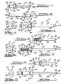
- FIG. 1is a perspective side view of a blind rivet according to the principles of the present invention
- FIG. 2is a second perspective side view of the blind rivet of FIG. 1 ;
- FIG. 3is a top view of the rivet of FIG. 1 ;
- FIG. 4is a side view of the rivet of FIG. 1 ;
- FIG. 5is a perspective side view of a blind rivet according to a second embodiment of the present invention.
- FIG. 6is a top view of the rivet of FIG. 5 ;
- FIG. 7is a side view of the rivet of FIG. 5 ;
- FIG. 8is a perspective side view of a blind rivet according to a third embodiment of the present invention.
- FIG. 9is a top view of the rivet of FIG. 8 ;
- FIG. 10is a side view of the rivet of FIG. 8 ;
- FIG. 11is an environmental view of the rivet of FIG. 1 prior to insertion into the workpiece
- FIG. 12is an environmental view of the rivet of FIG. 1 in a first position prior to deformation
- FIG. 13is an environmental view of the rivet of FIG. 1 in a second position after deformation of the rivet into a locked position;
- FIG. 14is an environmental view of the rivet of FIG. 1 in preparation to be removed from a workpiece.
- FIG. 15is an environmental view of the rivet of FIG. 1 upon removal of the rivet from the workpiece.
- the rivet 10can include a body 12 and a mandrel 14 .
- the body 12can be generally cylindrical and can be comprised of any material that is capable of plastically deforming in tension and failing in shear, such as aluminum or steel.
- the body 12can have a generally uniform exterior 18 ; however, the exterior 18 can include a plurality of serrations 20 , as shown in FIGS. 5 , 6 and 7 , to enable the body 12 to further engage a workpiece (not specifically shown).
- the body 12can further include a first end 22 , a second end 24 and a central bore 26 ( FIG. 13 ).
- the first end 22can be operable to interface with the mandrel 14 and plastically deform to secure a workpiece, as will be discussed in greater detail herein.
- the second end 24 of the body 12can include a radial flange 28 ( FIGS. 1 , 5 and 8 ), which can generally be formed onto the second end 24 ; however, any suitable post processing step could be used to couple the radial flange 28 to the second end 24 of the body 12 , such as welding or adhesives.
- the radial flange 28may comprise a plurality of flat portions 30 to form a generally hexagonal head, or in the alternative, as shown in FIGS.
- the radial flange 28may be oval in shape.
- the shape of the radial flange 28can generally be such that a first tool 32 (shown in FIG. 17 ) can engage the radial flange 28 .
- the first tool 32can be any suitable tool including a jaw 67 capable of grasping the radial flange 28 , such as a wrench, channel locks, socket wrench or the like.
- the radial flange 28may be of any shape operable to engage the jaw 67 of the first tool 32 , as will be discussed in greater detail herein.
- the second end 24 of the body 12can further include an annular groove 34 .
- the annular groove 34can generally be formed on the exterior 18 of the body 12 , typically adjacent to the radial flange 28 ; however, the annular groove 34 can generally be formed at any desired position on the body 12 (for example, the annular groove 34 could be formed at any location 25% to 75% along the body 12 from the first end 22 ).
- the groove 34is described herein as being annular, it will be understood that the actual shape of the groove 34 could be any shape that corresponds with the shape of the body 12 .
- the annular groove 34may be located at any desired position on the body 12 , and can alternatively be formed on an interior surface of the body 12 (not shown).
- the annular groove 34can have a rectangular cross-section as shown in FIGS. 12 and 13 , but any other cross-section, such as pointed or rounded, could be employed.
- the annular groove 34has a width W and a depth X (as best shown in FIG. 12 ) configured to enable the radial flange 28 to separate from the second end 24 of the body 12 during the application of a torsional force, as will be described in greater detail herein. Further, it will be understand that although only one annular groove 34 is illustrated herein, multiple annular grooves 34 could be employed.
- the central bore 26can extend from the first end 22 to the second end 24 of the body 12 and can be operable to receive the mandrel 14 , as best shown in FIG. 12 .
- the mandrel 14can include a mandrel head 36 coupled to a stem 38 , as best shown in FIG. 12 .
- the mandrel head 36can generally include a conical portion 40 coupled to a cylindrical base 42 .
- the cylindrical base 42can have a diameter D 1 , which can generally be greater than a diameter D 2 of the central bore 26 such that the mandrel head 36 can be unable to pass through the central bore 26 .
- D 1can generally be greater than a diameter D 2 of the central bore 26 such that the mandrel head 36 can be unable to pass through the central bore 26 .
- any appropriate shapecould be employed for the mandrel head 36 , as long as the diameter D 1 of the mandrel head 36 is greater than the diameter D 2 of the central bore 26 .
- the mandrel head 36can typically be formed onto the stem 38 .
- the stem 38can include a first end 44 coupled to the mandrel head 36 and a second end 46 .
- the stem 38can be generally cylindrical with a diameter D 3 , which can be at least slightly less than the diameter D 2 of the central bore 26 ; however, any suitable shape and diameter could be employed.
- the first end 44 of the stem 38can include a breakneck section 48 , which can be operable to enable the stem 38 to separate from the mandrel head 36 .
- the breakneck section 48can generally include a first tapered portion 50 , which can meet a second tapered portion 52 at a point 54 .
- the thickness T 2 of the point 54is such that the first end 44 of the stem 38 can be severed from the second end 46 of the stem 38 upon the application of a pre-determined tensile force, as will be discussed in greater detail herein.
- the second end 46 of the stem 38can include a tapered section 56 , which can terminate in a generally square portion 58 .
- the portion 58is shown as having a generally square cross-section; however, the portion 58 may be sized in any appropriate shape to interface with a pulling tool (not shown).
- the pulling toolcan be operable to apply a tensile force T to the stem 38 of the mandrel 14 via the portion 58 to set the rivet 10 .
- the body 12in order to set the rivet, the body 12 can be first slid onto the mandrel 14 , such that the mandrel head 36 can abut the first end 22 of the body 12 .
- the assembled rivet 10can be placed into a hole 60 formed in a workpiece 62 ( FIG. 12 ).
- the pulling tool(not shown) may be coupled to the portion 58 of the stem 38 of the mandrel 14 , to begin the application of the tensile force T to the mandrel 14 .
- the application of the tensile force Tcan cause the mandrel head 36 to apply a compression force to the first end 22 of the body 12 .
- the compressive loading of the first end 22 of the body 12can cause the first end of the body to 12 expand outward.
- the diameter D 1 of the mandrel head 36is greater than the diameter D 2 of the central bore 26 , the size of the mandrel head 36 coupled with the tensile force T can cause the first end 22 of the body 12 to plastically deform into an annular bulge 64 as shown in FIG. 13 .
- the continued application of the tensile force Tcan cause the breakneck portion 48 to fracture, severing the second end 46 of the stem 38 from the first end 44 of the stem 38 .
- the rivet 10can be firmly secured to the workpiece 62 .
- a second tool 66can be coupled to the first end 22 of the body 12 , around the annular bulge 64 .
- the second tool 66can be any suitable tool including a jaw 67 that is capable of grasping the annular bulge 64 , such as a wrench, channel locks, socket wrench or the like.
- the first tool 32can be coupled to the second end 24 of the body 12 , around the radial flange 28 .
- the first tool 32can be rotated while the second tool 66 is held fast, to create a torsional load that is transmitted along the radial flange 28 .
- tubular bodyincludes the plurality of serrations 20 as illustrated in FIG. 5
- the serrations 20can serve to firmly hold the body 12 within the workpiece 62 .
- the body 12 of the rivet 10will fail at the annular groove 34 , as shown in FIG. 15 .
- the torsional force from the first tool 32will cause the body 12 of the rivet 10 to fail in shear.
- the remaining body 12 of the rivet 10can then be pulled out of the workpiece 62 by the first tool 32 or tapped out of the workpiece 62 using a mallet and chisel, for example (not shown).
Landscapes
- Engineering & Computer Science (AREA)
- Mechanical Engineering (AREA)
- General Engineering & Computer Science (AREA)
- Insertion Pins And Rivets (AREA)
Abstract
Description
Claims (13)
Priority Applications (3)
| Application Number | Priority Date | Filing Date | Title |
|---|---|---|---|
| US11/335,769US7722303B2 (en) | 2005-02-11 | 2006-01-19 | Frangible blind rivet |
| JP2006028299AJP2006220300A (en) | 2005-02-11 | 2006-02-06 | Blind rivet capable of being fractured |
| EP06101355AEP1691087A3 (en) | 2005-02-11 | 2006-02-07 | Frangible Blind Rivet |
Applications Claiming Priority (2)
| Application Number | Priority Date | Filing Date | Title |
|---|---|---|---|
| US65202705P | 2005-02-11 | 2005-02-11 | |
| US11/335,769US7722303B2 (en) | 2005-02-11 | 2006-01-19 | Frangible blind rivet |
Publications (2)
| Publication Number | Publication Date |
|---|---|
| US20060182512A1 US20060182512A1 (en) | 2006-08-17 |
| US7722303B2true US7722303B2 (en) | 2010-05-25 |
Family
ID=36386390
Family Applications (1)
| Application Number | Title | Priority Date | Filing Date |
|---|---|---|---|
| US11/335,769Expired - Fee RelatedUS7722303B2 (en) | 2005-02-11 | 2006-01-19 | Frangible blind rivet |
Country Status (3)
| Country | Link |
|---|---|
| US (1) | US7722303B2 (en) |
| EP (1) | EP1691087A3 (en) |
| JP (1) | JP2006220300A (en) |
Cited By (5)
| Publication number | Priority date | Publication date | Assignee | Title |
|---|---|---|---|---|
| US20120034045A1 (en)* | 2010-08-06 | 2012-02-09 | Allfast Fastening Systems, Inc. | Temporary Rivet |
| US20120210557A1 (en)* | 2009-08-24 | 2012-08-23 | Newfrey Llc | Blind rivet |
| US8696719B2 (en) | 2010-06-03 | 2014-04-15 | Tarsus Medical Inc. | Methods and devices for treating hallux valgus |
| US9138219B2 (en) | 2010-12-29 | 2015-09-22 | Tarsus Medical Inc. | Methods and devices for treating a syndesmosis injury |
| US11898596B2 (en) | 2017-05-04 | 2024-02-13 | Maxime Grojean | Insert intended for the assembly of a first part and a second part by electric resistance welding, and assembly method using this insert |
Families Citing this family (8)
| Publication number | Priority date | Publication date | Assignee | Title |
|---|---|---|---|---|
| DE102007040371A1 (en)* | 2007-08-20 | 2009-02-26 | Adolf Würth GmbH & Co. KG | Rivet |
| US20110067323A1 (en)* | 2009-09-24 | 2011-03-24 | Kearney-National Inc | Breakaway utility pole with decorative base cover |
| KR101558700B1 (en) | 2013-12-19 | 2015-10-19 | 현대자동차주식회사 | Reverse Rivet |
| JP6920027B2 (en)* | 2015-03-17 | 2021-08-18 | ロレックス・ソシエテ・アノニムRolex Sa | Rivets for watches |
| US11125261B2 (en)* | 2016-08-12 | 2021-09-21 | Illinois Tool Works Inc. | Rivet fastener assemblies |
| DE102019101078A1 (en) | 2018-01-16 | 2019-07-18 | Illinois Tool Works Inc. | NIET FASTENER ELEMENT DESIGN AND METHOD OF USE THEREOF |
| US11268557B2 (en) | 2018-10-10 | 2022-03-08 | Illinois Tool Works Inc. | Rivet fastener assembly and method of use thereof |
| DE102023004670A1 (en)* | 2023-11-16 | 2024-08-14 | Mercedes-Benz Group AG | Component arrangement, method for producing such a component arrangement, method for separating such a component arrangement, motor vehicle with such a component arrangement |
Citations (29)
| Publication number | Priority date | Publication date | Assignee | Title |
|---|---|---|---|---|
| US2612073A (en)* | 1944-04-19 | 1952-09-30 | A T S Company Ltd | Hollow threaded rivet |
| US3682508A (en) | 1969-11-19 | 1972-08-08 | Franklin S Briles | Re-usable, spin-stopping fastener |
| US3842710A (en) | 1971-09-10 | 1974-10-22 | Illinois Tool Works | Removable rivet |
| US3964364A (en) | 1975-04-17 | 1976-06-22 | Hartwell Corporation | Initially single piece rotatable fastener |
| US4169004A (en) | 1975-09-24 | 1979-09-25 | The Procter & Gamble Company | Water frangible end seal for hydro-dissociative agglomerate tampon |
| US4216697A (en) | 1978-12-12 | 1980-08-12 | Leroy Wilson | Two-piece reusable fastener |
| US4263833A (en) | 1979-05-15 | 1981-04-28 | Illinois Tool Works Inc. | Removable one-piece drive rivet |
| US4293258A (en)* | 1977-10-04 | 1981-10-06 | Microdot Inc. | Self drilling blind rivet |
| US4376604A (en)* | 1981-01-29 | 1983-03-15 | Monogram Industries, Inc. | Blind fastener for composite materials |
| US4436467A (en)* | 1980-07-23 | 1984-03-13 | Larsson Sven B | Easily releasable blind rivets |
| US4541761A (en)* | 1983-09-26 | 1985-09-17 | Usm Corporation | Easily removed blind rivet |
| US4585382A (en)* | 1983-12-01 | 1986-04-29 | Usm Corporation | Easily removable rivet with tab |
| US5062546A (en) | 1990-05-15 | 1991-11-05 | Mackal Glenn H | Snap rivet safety lock for inflators |
| US5248231A (en)* | 1991-10-09 | 1993-09-28 | Avdel System Limited | Self-plugging blind rivet |
| US5346347A (en) | 1992-01-24 | 1994-09-13 | Clipp-Off | Removable fastener capable of elastic deformation |
| US5496140A (en)* | 1993-12-17 | 1996-03-05 | Gesipa Blindniettechnik Gmbh | Blind rivets and method for its manufacture |
| US5551816A (en)* | 1994-04-12 | 1996-09-03 | Avdel Systems Limited | Removable rivet and method of removing the head from the shank of the rivet |
| GB2332722A (en) | 1997-12-29 | 1999-06-30 | Emhart Inc | Blind rivet with work hardened groove in shank |
| JP2000084755A (en) | 1998-09-08 | 2000-03-28 | Ricoh Co Ltd | Fastening member, fastening member disassembly method and disassembly tool |
| US6171038B1 (en) | 1998-11-12 | 2001-01-09 | Textron Inc. | Tapered shank rivet |
| US6254324B1 (en) | 1999-02-19 | 2001-07-03 | Emhart Inc. | Blind rivet |
| USD460911S1 (en) | 2000-03-30 | 2002-07-30 | Honda Giken Kogyo Kabushiki Kaisha | Rivet |
| US20020119024A1 (en) | 2000-12-21 | 2002-08-29 | Gary Jennings | Blind rivet |
| US20040022597A1 (en) | 2002-05-08 | 2004-02-05 | Jones Steven V. | Blind rivet |
| US6702232B2 (en) | 2002-04-05 | 2004-03-09 | The Boeing Company | Jam resistant and intruder-proof flight deck door |
| US20040071525A1 (en) | 2002-06-06 | 2004-04-15 | M. E. Millington | Peel-type blind rivet |
| US20040071522A1 (en) | 2002-06-06 | 2004-04-15 | Millington M. E. | Peel-type blind rivet |
| US6746191B2 (en) | 2001-02-06 | 2004-06-08 | Illinois Tool Works Inc. | Reusable rivet |
| US7182561B2 (en)* | 2001-12-14 | 2007-02-27 | Newfrey Llc | Blind rivet with steal |
Family Cites Families (3)
| Publication number | Priority date | Publication date | Assignee | Title |
|---|---|---|---|---|
| GB2155578B (en)* | 1984-03-13 | 1987-10-14 | Burroughs Corp | Tamper-proof blind rivet assembly |
| JPS60173713U (en)* | 1984-04-26 | 1985-11-18 | 日新電機株式会社 | rivets |
| JP3345715B2 (en)* | 1999-04-07 | 2002-11-18 | 福井鋲螺株式会社 | Separable rivet and swaging tool used for fastening this rivet |
- 2006
- 2006-01-19USUS11/335,769patent/US7722303B2/ennot_activeExpired - Fee Related
- 2006-02-06JPJP2006028299Apatent/JP2006220300A/enactivePending
- 2006-02-07EPEP06101355Apatent/EP1691087A3/ennot_activeWithdrawn
Patent Citations (30)
| Publication number | Priority date | Publication date | Assignee | Title |
|---|---|---|---|---|
| US2612073A (en)* | 1944-04-19 | 1952-09-30 | A T S Company Ltd | Hollow threaded rivet |
| US3682508A (en) | 1969-11-19 | 1972-08-08 | Franklin S Briles | Re-usable, spin-stopping fastener |
| US3842710A (en) | 1971-09-10 | 1974-10-22 | Illinois Tool Works | Removable rivet |
| US3964364A (en) | 1975-04-17 | 1976-06-22 | Hartwell Corporation | Initially single piece rotatable fastener |
| US4169004A (en) | 1975-09-24 | 1979-09-25 | The Procter & Gamble Company | Water frangible end seal for hydro-dissociative agglomerate tampon |
| US4293258A (en)* | 1977-10-04 | 1981-10-06 | Microdot Inc. | Self drilling blind rivet |
| US4216697A (en) | 1978-12-12 | 1980-08-12 | Leroy Wilson | Two-piece reusable fastener |
| US4263833A (en) | 1979-05-15 | 1981-04-28 | Illinois Tool Works Inc. | Removable one-piece drive rivet |
| US4436467A (en)* | 1980-07-23 | 1984-03-13 | Larsson Sven B | Easily releasable blind rivets |
| US4376604A (en)* | 1981-01-29 | 1983-03-15 | Monogram Industries, Inc. | Blind fastener for composite materials |
| US4541761A (en)* | 1983-09-26 | 1985-09-17 | Usm Corporation | Easily removed blind rivet |
| US4585382A (en)* | 1983-12-01 | 1986-04-29 | Usm Corporation | Easily removable rivet with tab |
| US5062546A (en) | 1990-05-15 | 1991-11-05 | Mackal Glenn H | Snap rivet safety lock for inflators |
| US5248231A (en)* | 1991-10-09 | 1993-09-28 | Avdel System Limited | Self-plugging blind rivet |
| US5346347A (en) | 1992-01-24 | 1994-09-13 | Clipp-Off | Removable fastener capable of elastic deformation |
| US5496140A (en)* | 1993-12-17 | 1996-03-05 | Gesipa Blindniettechnik Gmbh | Blind rivets and method for its manufacture |
| US5551816A (en)* | 1994-04-12 | 1996-09-03 | Avdel Systems Limited | Removable rivet and method of removing the head from the shank of the rivet |
| GB2332722A (en) | 1997-12-29 | 1999-06-30 | Emhart Inc | Blind rivet with work hardened groove in shank |
| JP2000084755A (en) | 1998-09-08 | 2000-03-28 | Ricoh Co Ltd | Fastening member, fastening member disassembly method and disassembly tool |
| US6171038B1 (en) | 1998-11-12 | 2001-01-09 | Textron Inc. | Tapered shank rivet |
| US6254324B1 (en) | 1999-02-19 | 2001-07-03 | Emhart Inc. | Blind rivet |
| USD460911S1 (en) | 2000-03-30 | 2002-07-30 | Honda Giken Kogyo Kabushiki Kaisha | Rivet |
| US20020119024A1 (en) | 2000-12-21 | 2002-08-29 | Gary Jennings | Blind rivet |
| US6746191B2 (en) | 2001-02-06 | 2004-06-08 | Illinois Tool Works Inc. | Reusable rivet |
| US7182561B2 (en)* | 2001-12-14 | 2007-02-27 | Newfrey Llc | Blind rivet with steal |
| US6702232B2 (en) | 2002-04-05 | 2004-03-09 | The Boeing Company | Jam resistant and intruder-proof flight deck door |
| US20040022597A1 (en) | 2002-05-08 | 2004-02-05 | Jones Steven V. | Blind rivet |
| US20040071525A1 (en) | 2002-06-06 | 2004-04-15 | M. E. Millington | Peel-type blind rivet |
| US20040071522A1 (en) | 2002-06-06 | 2004-04-15 | Millington M. E. | Peel-type blind rivet |
| US6905296B2 (en)* | 2002-06-06 | 2005-06-14 | Newfrey Llc | Peel-type blind rivet |
Cited By (6)
| Publication number | Priority date | Publication date | Assignee | Title |
|---|---|---|---|---|
| US20120210557A1 (en)* | 2009-08-24 | 2012-08-23 | Newfrey Llc | Blind rivet |
| US8696719B2 (en) | 2010-06-03 | 2014-04-15 | Tarsus Medical Inc. | Methods and devices for treating hallux valgus |
| US20120034045A1 (en)* | 2010-08-06 | 2012-02-09 | Allfast Fastening Systems, Inc. | Temporary Rivet |
| US20130047411A1 (en)* | 2010-08-06 | 2013-02-28 | Allfast Fastening Systems, Inc. | Temporary Rivet |
| US9138219B2 (en) | 2010-12-29 | 2015-09-22 | Tarsus Medical Inc. | Methods and devices for treating a syndesmosis injury |
| US11898596B2 (en) | 2017-05-04 | 2024-02-13 | Maxime Grojean | Insert intended for the assembly of a first part and a second part by electric resistance welding, and assembly method using this insert |
Also Published As
| Publication number | Publication date |
|---|---|
| EP1691087A3 (en) | 2011-08-24 |
| EP1691087A2 (en) | 2006-08-16 |
| JP2006220300A (en) | 2006-08-24 |
| US20060182512A1 (en) | 2006-08-17 |
Similar Documents
| Publication | Publication Date | Title |
|---|---|---|
| US7722303B2 (en) | Frangible blind rivet | |
| US8517649B2 (en) | Dual-action disposable clamp | |
| AU752826B2 (en) | Blind fastener | |
| US7980800B2 (en) | Blind fastener and method of removing it from a workpiece | |
| US9212678B2 (en) | Fastener and method of installing same | |
| EP2647851B1 (en) | Fastener and method of installing same | |
| US20090031549A1 (en) | Blind rivet | |
| JP2006342963A (en) | Improved blind rivet | |
| US10941799B2 (en) | Deformable sleeve nut and a method of manufacturing | |
| US9644659B2 (en) | Temporary clamp up system for sealant squeeze out in lock bolt installations | |
| JP2005518509A (en) | Honeycomb rivet | |
| JP2005511319A (en) | Fastening method | |
| EP1327082B1 (en) | Blind fastener | |
| US8029220B2 (en) | Blind rivet assembly | |
| US9903403B2 (en) | Fastener and method of installing same | |
| EP2920474B1 (en) | Rivet | |
| JP2013249850A (en) | Blind rivet and method of fastening the same | |
| KR20170077770A (en) | Fastener and fastening mechanism | |
| KR101449188B1 (en) | Fastening structure of blind bolt with a stabel head | |
| EP0152531A1 (en) | Blind fastener | |
| EP0154817A1 (en) | Method of installing flush break blind fasteners and fasteners for same | |
| ZA200507051B (en) | Blind fastener and method of removing it from a workpiece | |
| JP2000084757A (en) | Fastening member, spacer member of fastening member and disassembly method | |
| AU2005220176A1 (en) | An improved rivet assembly | |
| GB2416377A (en) | Blind rivet with retained mandrel |
Legal Events
| Date | Code | Title | Description |
|---|---|---|---|
| AS | Assignment | Owner name:NEWFREY LLC,DELAWARE Free format text:ASSIGNMENT OF ASSIGNORS INTEREST;ASSIGNOR:WILLIAMS, MICHAEL K.;REEL/FRAME:017502/0078 Effective date:20060119 Owner name:NEWFREY LLC, DELAWARE Free format text:ASSIGNMENT OF ASSIGNORS INTEREST;ASSIGNOR:WILLIAMS, MICHAEL K.;REEL/FRAME:017502/0078 Effective date:20060119 | |
| FEPP | Fee payment procedure | Free format text:PAYOR NUMBER ASSIGNED (ORIGINAL EVENT CODE: ASPN); ENTITY STATUS OF PATENT OWNER: LARGE ENTITY | |
| STCF | Information on status: patent grant | Free format text:PATENTED CASE | |
| FPAY | Fee payment | Year of fee payment:4 | |
| MAFP | Maintenance fee payment | Free format text:PAYMENT OF MAINTENANCE FEE, 8TH YEAR, LARGE ENTITY (ORIGINAL EVENT CODE: M1552) Year of fee payment:8 | |
| FEPP | Fee payment procedure | Free format text:MAINTENANCE FEE REMINDER MAILED (ORIGINAL EVENT CODE: REM.); ENTITY STATUS OF PATENT OWNER: LARGE ENTITY | |
| LAPS | Lapse for failure to pay maintenance fees | Free format text:PATENT EXPIRED FOR FAILURE TO PAY MAINTENANCE FEES (ORIGINAL EVENT CODE: EXP.); ENTITY STATUS OF PATENT OWNER: LARGE ENTITY | |
| STCH | Information on status: patent discontinuation | Free format text:PATENT EXPIRED DUE TO NONPAYMENT OF MAINTENANCE FEES UNDER 37 CFR 1.362 | |
| STCH | Information on status: patent discontinuation | Free format text:PATENT EXPIRED DUE TO NONPAYMENT OF MAINTENANCE FEES UNDER 37 CFR 1.362 | |
| FP | Lapsed due to failure to pay maintenance fee | Effective date:20220525 |