US7722114B2 - Zero gravity wall hugger recliner - Google Patents
Zero gravity wall hugger reclinerDownload PDFInfo
- Publication number
- US7722114B2 US7722114B2US12/101,448US10144808AUS7722114B2US 7722114 B2US7722114 B2US 7722114B2US 10144808 AUS10144808 AUS 10144808AUS 7722114 B2US7722114 B2US 7722114B2
- Authority
- US
- United States
- Prior art keywords
- seat
- trolley
- recliner
- assembly
- frame
- Prior art date
- Legal status (The legal status is an assumption and is not a legal conclusion. Google has not performed a legal analysis and makes no representation as to the accuracy of the status listed.)
- Expired - Fee Related
Links
- 230000005484gravityEffects0.000titleclaimsabstractdescription17
- 230000007246mechanismEffects0.000description4
- 230000006872improvementEffects0.000description3
- 230000004075alterationEffects0.000description2
- 230000004048modificationEffects0.000description2
- 238000012986modificationMethods0.000description2
- 230000009471actionEffects0.000description1
- 230000008859changeEffects0.000description1
- 238000010276constructionMethods0.000description1
- 230000000694effectsEffects0.000description1
- 239000000463materialSubstances0.000description1
- 239000002184metalSubstances0.000description1
- 230000008520organizationEffects0.000description1
- 230000004044responseEffects0.000description1
Images


Classifications
- A—HUMAN NECESSITIES
- A47—FURNITURE; DOMESTIC ARTICLES OR APPLIANCES; COFFEE MILLS; SPICE MILLS; SUCTION CLEANERS IN GENERAL
- A47C—CHAIRS; SOFAS; BEDS
- A47C1/00—Chairs adapted for special purposes
- A47C1/02—Reclining or easy chairs
- A47C1/031—Reclining or easy chairs having coupled concurrently adjustable supporting parts
- A47C1/034—Reclining or easy chairs having coupled concurrently adjustable supporting parts the parts including a leg-rest or foot-rest
- A47C1/035—Reclining or easy chairs having coupled concurrently adjustable supporting parts the parts including a leg-rest or foot-rest in combination with movably coupled seat and back-rest, i.e. the seat and back-rest being movably coupled in such a way that the extension mechanism of the foot-rest is actuated at least by the relative movements of seat and backrest
- A47C1/0352—Reclining or easy chairs having coupled concurrently adjustable supporting parts the parts including a leg-rest or foot-rest in combination with movably coupled seat and back-rest, i.e. the seat and back-rest being movably coupled in such a way that the extension mechanism of the foot-rest is actuated at least by the relative movements of seat and backrest characterised by coupled seat and back-rest slidingly movable in the base frame, e.g. by rollers
Definitions
- This inventionrelates to reclining furniture and more particularly to zero gravity recliners.
- the reclinerincludes one or more improvements directed to different features of the recliner.
- the reclineris motor drive.
- the reclineris a wall-hugger allowing it to be placed close to the wall when in the upright position and without moving it away from the wall when reclined, has a zero gravity configuration when reclined supporting the legs of the occupant above the heart, and when the recliner is upright the leg rest retracts under the plan of the seat.
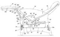
- FIG. 1is a vertical cross-sectional view of a zero gravity reclining chair in the reclined position, embodying the present invention
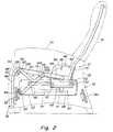
- FIG. 2is a cross-sectional view similar to FIG. 1 but showing the chair in the upright or sitting position;
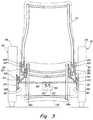
- FIG. 3is a rear elevation view of the chair in the upright position.
- FIG. 4is a fragmentary view of a portion of the reclining mechanism and particularly showing the mechanism for raising and lowering the leg rest.
- the Zero Gravity Recliner of the present invention in the embodiment illustratedincludes in its general organization a base 10 that carries the chair assembly 12 having a seat 14 , backrest 16 and leg rest 18 , the frame of the seat and backrest are identified as 14 a and 16 a .
- the chair assembly 12is supported on the base by a motion assembly 20 that enables the chair assembly to move between zero gravity reclined and upright positions shown respectively in FIGS. 1 and 2 .
- the motion assemblyis driven by a motor 22 having a screw-type drive shaft 24 connected between the fixed base 10 and the motion assembly 20 .
- the base 10 in the embodiment illustratedincludes a pair of side support panels 30 , one on each side of the chair that extend fore and aft inside the frame sides 32 that define the chair arm rests 34 .
- the side panels 32are connected together by front and rear spreaders 36 and 36 a to form a rigid frame, and each of the panels 30 mounted on the side walls 32 carries an essentially horizontal track 40 that extends front-to-back over a substantial portion of the length of the supports. While the tracks 40 shown are horizontal, in other embodiments they may be inclined and/or non-linear in shape.
- the chair assembly 12is supported on the base 10 by a roller trolley 46 that may be generally U-shaped having a bottom plate 48 and side plates 50 (see FIG. 3 ).
- the bottom plate 48 and the side plates 50may be a unitary structure either of one piece or of several pieces separately fabricated and secured together.
- the trolley 46is made of metal but other materials may be used.
- Rollers 52are mounted on the trolley side plates 50 so as to support the trolley for back-and-forth motion along the path defined by the tracks 40 .
- the motor 22is carried on a motor mount 53 attached to the front spreader 36 , and its shaft 24 is attached to a bracket 56 connected to the bottom wall 48 of trolley 46 . Because the bracket 56 is fixed to the trolley and the motor is fixed with respect to the base, rotation of the screw shaft 24 will move the trolley 46 back and forth on the tracks 40 determined by the rotational direction of the motor.
- the motor 22is mounted in a fixed location, for example, to the front spreader 36 of the frame and the free end of the screw shaft 24 is connected to the movable trolley 46 , the assembly may be reversed so that the motor is attached to the rear spreader 36 a or some other fixed location and the end of the screw shaft is attached to the trolley, in the direction opposite that shown.
- the motor 22may be attached to the trolley 46 and the screw may be coupled to either of the spreaders or at another fixed location.
- Each of the side plates 50 of the roller trolley 46carries a motion bracket 64 .
- the motion brackets 64are pivotally connected to the side members 50 by pivot pins 66 .
- the motion brackets 64carry the seat frame 14 a and backrest frame 16 a on the bracket flanges 68 and 70 respectively, that are rigidly connected to the seat and backrest frames. In that fashion the frames of the seat and backrest are in a fixed angular relationship to one another that does not change when the two pivot as a rigid assembly with the motion brackets 46 .
- the chair assembly 12moves to and fro on the stationary base frame 10 (compare FIGS. 1 and 2 ).
- leg rest 18as part of the chair assembly moves with the seat 14 and backrest 16 , but its angular position is not fixed with respect to those chair parts. Rather, the leg rest 18 is pivotally mounted at the front end of the seat, and as explained in detail below, it pivots with respect to the seat by the action imparted to it by the leg rest control bars 80 .
- FIG. 4shows a skeletal representation of the seat frame 14 a , leg rest frame 18 a and push bar 80 assembly along with brackets 86 , pivot bars 88 and pivots 90 .
- the leg rest frame 18 apivots on the seat by virtue of the connections of the brackets 86 and pivot arms 88 on each side of the assembly (compare FIGS. 1 and 2 ).
- Pivotal motion of the unitized seat 14 and backrest 16 on the motion bracket 64is imparted by actuating levers 92 pivotally mounted on each side of the seat at their lower ends 94 to fixed side supports 30 and at their upper ends 96 to the sides of the seat frame 14 a .
- the connections of the ends 94 and 96 of the actuating levers 92are provided by pivots 98 and 100 .
- the side supports 30establish fixed pivots 98 at the lower ends of actuating levers 92 , and the upper pivots 100 move as the seat 14 moves with the trolley 46 and motion bracket 64 .
- the actuating levers 92pivot upwardly to a more vertical position (compare FIGS. 1 and 2 ) about pivots 98 and elevate the seat 14 and tilt the backrest rearwardly to a reclined position.
- Footrest control bars 80that control the motion of the footrest with respect to the seat, are connected at one end 104 to the actuating levers 92 at pivot 106 , and the other ends 108 of the control bars 80 are connected at pivot 110 to the end 112 of the footrest 18 .
- the control bars 80pivot the leg rest 18 about its pivots 90 on the brackets 86 causing the footrest to rise from the down or retracted position under the front edge of the seat 14 (see FIG. 2 ) to a horizontal position wherein the leg rest extends in a forward direction from the front edge of the seat to create a zero gravity support for the legs of the occupant of the chair above his/her heart (see FIG. 1 ).
- the combination of the moving trolley 46 , actuating levers 92 and control bars 80direct the recliner to its upright and reclined positions and simultaneously the leg rest to its retracted ( FIG. 2 ) and zero gravity positions ( FIG. 1 ) in response to operation of the motor.
- the motion of the trolley 46 moving the seat and backrest in a forward directionenable the recliner to be positioned very close to a wall behind the backrest so as to minimize the space required for the recliner in its upright position.
- the location of the recliner in proximity to a wallis in part determined by the height of the backrest and the thickness of its cushions, but spacing of the backrest just a few inches from a wall is sufficient to achieve the wall hugging effect.
- the mechanismenables the recliner to occupy a relatively small floor space as the leg rest is fully retracted when the recliner is upright, unlike most zero gravity furniture. It will also be appreciated that the motor powered mechanism may be used in other recliners that do not include retractable leg rests.
Landscapes
- Health & Medical Sciences (AREA)
- Dentistry (AREA)
- General Health & Medical Sciences (AREA)
- Chairs For Special Purposes, Such As Reclining Chairs (AREA)
Abstract
Description
Claims (7)
Priority Applications (1)
| Application Number | Priority Date | Filing Date | Title |
|---|---|---|---|
| US12/101,448US7722114B2 (en) | 2008-04-11 | 2008-04-11 | Zero gravity wall hugger recliner |
Applications Claiming Priority (1)
| Application Number | Priority Date | Filing Date | Title |
|---|---|---|---|
| US12/101,448US7722114B2 (en) | 2008-04-11 | 2008-04-11 | Zero gravity wall hugger recliner |
Publications (2)
| Publication Number | Publication Date |
|---|---|
| US20090256402A1 US20090256402A1 (en) | 2009-10-15 |
| US7722114B2true US7722114B2 (en) | 2010-05-25 |
Family
ID=41163371
Family Applications (1)
| Application Number | Title | Priority Date | Filing Date |
|---|---|---|---|
| US12/101,448Expired - Fee RelatedUS7722114B2 (en) | 2008-04-11 | 2008-04-11 | Zero gravity wall hugger recliner |
Country Status (1)
| Country | Link |
|---|---|
| US (1) | US7722114B2 (en) |
Cited By (15)
| Publication number | Priority date | Publication date | Assignee | Title |
|---|---|---|---|---|
| US20100127538A1 (en)* | 2008-11-24 | 2010-05-27 | Hoffman D Stephen | Rocking-Reclining Seating Unit with Power Actuator |
| US20110198894A1 (en)* | 2010-02-14 | 2011-08-18 | Ping Hsieh | Chair with electrically adjustable components |
| US20110248545A1 (en)* | 2010-04-13 | 2011-10-13 | La-Z-Boy Incorporated | Power actuated wall proximity furniture member |
| US20120286557A1 (en)* | 2010-12-29 | 2012-11-15 | Hoffman D Stephen | Reclining chair with tilting action to provide heart-rest position |
| CN103892984A (en)* | 2014-01-17 | 2014-07-02 | 浙江豪中豪健康产品有限公司 | Null space massage chair capable of simulating zero gravity |
| US8915544B2 (en) | 2011-08-26 | 2014-12-23 | La-Z-Boy Incorporated | Furniture member with mechanism for powered occupant lift |
| US9010851B2 (en) | 2013-09-19 | 2015-04-21 | La-Z-Boy Incorporated | Furniture member power mechanism with selectable lift movement and zero gravity position |
| US9326606B2 (en) | 2013-09-19 | 2016-05-03 | La-Z-Boy Incorporated | Furniture member power mechanism with zero gravity and rear tilt positions |
| US9358167B2 (en) | 2013-09-19 | 2016-06-07 | La-Z-Boy Incorporated | Furniture member power mechanism with selectable lift movement and zero gravity position |
| DE202016104352U1 (en) | 2016-08-08 | 2016-08-18 | Ciar S.P.A. | seat |
| USD775845S1 (en) | 2015-11-30 | 2017-01-10 | Bret Christopher Reilly | Zero gravity chair |
| US9597243B1 (en)* | 2014-02-15 | 2017-03-21 | Midmark Corporation | Medical procedure chair |
| US9907713B2 (en)* | 2012-11-06 | 2018-03-06 | Invacare International Sarl | Wheelchair including a tiltable seat |
| US9994321B2 (en)* | 2014-04-03 | 2018-06-12 | Zodiac Seats Us Llc | Reclining passenger seat |
| EP3143902B1 (en) | 2015-09-15 | 2020-01-08 | Ciar S.P.A. | Wall hugger recliner |
Families Citing this family (22)
| Publication number | Priority date | Publication date | Assignee | Title |
|---|---|---|---|---|
| US8573687B2 (en)* | 2010-08-27 | 2013-11-05 | L & P Property Management Company | Zero-wall clearance linkage mechanism for providing additional layout |
| US9386857B2 (en) | 2010-08-27 | 2016-07-12 | L & P Property Management Company | Zero-wall clearance linkage mechanism for providing additional layout |
| CN102415933B (en)* | 2011-08-29 | 2013-06-05 | 宁波康福特健身器械有限公司 | Massage chair capable of simulating zero gravity state |
| TWM426338U (en)* | 2011-10-03 | 2012-04-11 | Johnson Health Tech Co Ltd | Flat reclining chair |
| CN103584976B (en)* | 2013-11-22 | 2016-04-20 | 山东康泰实业有限公司 | Massage chair capable of sliding forwards to achieve zero gravity state |
| CN103815687B (en)* | 2014-01-16 | 2016-11-16 | 山东康泰实业有限公司 | A kind of arbitrarily angled massage armchair being massaged into huckle from head |
| WO2015148484A1 (en)* | 2014-03-24 | 2015-10-01 | L & P Property Management Company | Zero-wall clearance linkage mechanism including a single drive link |
| CN103892986B (en)* | 2014-04-14 | 2016-01-20 | 杭州松研电器有限公司 | A kind of list possessing zero gravity functions drives massage armchair |
| US10500434B2 (en)* | 2015-02-16 | 2019-12-10 | Kuang Yu Metal Working Co., Ltd. | Exercising device and operating method thereof |
| US20170128320A1 (en)* | 2015-11-10 | 2017-05-11 | Hsin Hao Health Materials Co., Ltd. | Massage chair |
| CN107752498B (en)* | 2017-11-29 | 2024-06-21 | 台州风锐电子科技有限公司 | Zero gravity computer cabin |
| US10881209B2 (en)* | 2018-01-12 | 2021-01-05 | L&P Property Management Company | Recliner seating mechanism with seat extension |
| US10780003B2 (en)* | 2019-01-04 | 2020-09-22 | Haworth, Inc. | Adjustable ergonomic chair |
| CN109674264B (en)* | 2019-01-28 | 2024-10-01 | 奥佳华智能健康科技集团股份有限公司 | Chair frame |
| CN111642922B (en)* | 2020-06-05 | 2025-02-14 | 锐迈科技股份有限公司 | Adjustable seat bracket |
| CN216364384U (en)* | 2021-11-30 | 2022-04-26 | 德沃康科技集团有限公司 | Zero-gravity experience seat frame with lifting legs |
| CA3157037A1 (en) | 2021-11-30 | 2023-05-30 | Dewertokin Technology Group Co., Ltd. | Seat frame |
| CN114274848B (en)* | 2022-01-20 | 2023-03-14 | 延锋国际座椅系统有限公司 | Zero-gravity seat |
| CN115054079A (en)* | 2022-06-29 | 2022-09-16 | 东莞市瑞豪家具制造有限公司 | Zero-gravity zero-wall-leaning seat frame |
| CN115107598B (en)* | 2022-07-05 | 2024-08-06 | 诺博汽车系统有限公司 | Zero gravity seat and vehicle with same |
| EP4338642A1 (en)* | 2022-09-13 | 2024-03-20 | Motion SpA | Method for tilting a reclining chair |
| CN116671743A (en)* | 2023-07-22 | 2023-09-01 | 顾家家居股份有限公司 | Linkage mechanism and seat |
Citations (20)
| Publication number | Priority date | Publication date | Assignee | Title |
|---|---|---|---|---|
| US3758151A (en) | 1972-02-01 | 1973-09-11 | Dual Manuf And Eng Inc | Reclining chair |
| US3858932A (en) | 1973-05-23 | 1975-01-07 | Legget & Platt Inc | Reclining chair assembly |
| DE2629475A1 (en) | 1975-08-11 | 1977-02-24 | Hoover Seng Co | Reclining arm chair with folding foot rest - foot rest comes automatically out when chair is reclined while seat moves forward away from any obstacle behind |
| US4072342A (en) | 1976-04-20 | 1978-02-07 | Pontiac Furniture Industries, Inc. | Recliner chair |
| US4077663A (en) | 1976-05-05 | 1978-03-07 | Mohasco Corporation | Recliner loungers |
| US4216992A (en) | 1978-12-26 | 1980-08-12 | Leggett & Platt, Incorporated | Unitized close-to-the-wall recliner chair mechanism |
| US4226468A (en) | 1978-03-13 | 1980-10-07 | Pontiac Furniture Industries, Inc. | Wall-clearing recliner |
| US4367895A (en)* | 1980-05-29 | 1983-01-11 | La-Z-Boy Chair Company | Reclinable chair |
| US5004647A (en)* | 1986-03-21 | 1991-04-02 | W. R. Grace & Co.-Conn. | Oxygen barrier biaxially oriented film |
| US5072988A (en) | 1987-06-09 | 1991-12-17 | Super Sagless Corporation | Wall proximity chair |
| US5120107A (en)* | 1989-06-05 | 1992-06-09 | Rogers Jr Walter C | Recliner chair |
| US5348367A (en)* | 1991-07-01 | 1994-09-20 | Lumex, Inc. | Reclining chair mechanism |
| US5823614A (en) | 1996-06-14 | 1998-10-20 | L&P Property Management Company | Three-way reclining furniture item |
| US6032976A (en)* | 1997-09-08 | 2000-03-07 | Sunrise Medical Hhg Inc. | Wheelchair with tilting seat |
| US6135554A (en)* | 1998-08-10 | 2000-10-24 | Tsun; Tsai Sung | Recliner chair |
| US6227489B1 (en)* | 1998-05-15 | 2001-05-08 | Koito Industries, Ltd. | Aircraft seat apparatus |
| US6357776B1 (en)* | 1997-10-02 | 2002-03-19 | Invacare Corporation | Constant center of gravity tiltable chair of a wheelchair |
| EP1555005A2 (en) | 2004-01-19 | 2005-07-20 | Omron Healthcare Co., Ltd. | Reclinable chair |
| US7147278B2 (en) | 2004-08-26 | 2006-12-12 | L&P Property Management Company | Linkage mechanism for use in motion furniture |
| US7516977B2 (en)* | 2006-03-30 | 2009-04-14 | Cycling & Health Tech Industry R&D Center | Seat adjusting mechanism of a motorized wheelchair |
- 2008
- 2008-04-11USUS12/101,448patent/US7722114B2/ennot_activeExpired - Fee Related
Patent Citations (20)
| Publication number | Priority date | Publication date | Assignee | Title |
|---|---|---|---|---|
| US3758151A (en) | 1972-02-01 | 1973-09-11 | Dual Manuf And Eng Inc | Reclining chair |
| US3858932A (en) | 1973-05-23 | 1975-01-07 | Legget & Platt Inc | Reclining chair assembly |
| DE2629475A1 (en) | 1975-08-11 | 1977-02-24 | Hoover Seng Co | Reclining arm chair with folding foot rest - foot rest comes automatically out when chair is reclined while seat moves forward away from any obstacle behind |
| US4072342A (en) | 1976-04-20 | 1978-02-07 | Pontiac Furniture Industries, Inc. | Recliner chair |
| US4077663A (en) | 1976-05-05 | 1978-03-07 | Mohasco Corporation | Recliner loungers |
| US4226468A (en) | 1978-03-13 | 1980-10-07 | Pontiac Furniture Industries, Inc. | Wall-clearing recliner |
| US4216992A (en) | 1978-12-26 | 1980-08-12 | Leggett & Platt, Incorporated | Unitized close-to-the-wall recliner chair mechanism |
| US4367895A (en)* | 1980-05-29 | 1983-01-11 | La-Z-Boy Chair Company | Reclinable chair |
| US5004647A (en)* | 1986-03-21 | 1991-04-02 | W. R. Grace & Co.-Conn. | Oxygen barrier biaxially oriented film |
| US5072988A (en) | 1987-06-09 | 1991-12-17 | Super Sagless Corporation | Wall proximity chair |
| US5120107A (en)* | 1989-06-05 | 1992-06-09 | Rogers Jr Walter C | Recliner chair |
| US5348367A (en)* | 1991-07-01 | 1994-09-20 | Lumex, Inc. | Reclining chair mechanism |
| US5823614A (en) | 1996-06-14 | 1998-10-20 | L&P Property Management Company | Three-way reclining furniture item |
| US6032976A (en)* | 1997-09-08 | 2000-03-07 | Sunrise Medical Hhg Inc. | Wheelchair with tilting seat |
| US6357776B1 (en)* | 1997-10-02 | 2002-03-19 | Invacare Corporation | Constant center of gravity tiltable chair of a wheelchair |
| US6227489B1 (en)* | 1998-05-15 | 2001-05-08 | Koito Industries, Ltd. | Aircraft seat apparatus |
| US6135554A (en)* | 1998-08-10 | 2000-10-24 | Tsun; Tsai Sung | Recliner chair |
| EP1555005A2 (en) | 2004-01-19 | 2005-07-20 | Omron Healthcare Co., Ltd. | Reclinable chair |
| US7147278B2 (en) | 2004-08-26 | 2006-12-12 | L&P Property Management Company | Linkage mechanism for use in motion furniture |
| US7516977B2 (en)* | 2006-03-30 | 2009-04-14 | Cycling & Health Tech Industry R&D Center | Seat adjusting mechanism of a motorized wheelchair |
Non-Patent Citations (1)
| Title |
|---|
| Leggett & Platt "Adjustables" from a brochure. |
Cited By (22)
| Publication number | Priority date | Publication date | Assignee | Title |
|---|---|---|---|---|
| US20100127538A1 (en)* | 2008-11-24 | 2010-05-27 | Hoffman D Stephen | Rocking-Reclining Seating Unit with Power Actuator |
| US8113574B2 (en)* | 2008-11-24 | 2012-02-14 | Ultra-Mek, Inc. | Rocking-reclining seating unit with power actuator |
| US20120153704A1 (en)* | 2008-11-24 | 2012-06-21 | Hoffman D Stephen | Rocking-reclining seating unit with power actuator |
| US8459733B2 (en)* | 2008-11-24 | 2013-06-11 | Ultra-Mek, Inc. | Rocking-reclining seating unit with power actuator |
| US20110198894A1 (en)* | 2010-02-14 | 2011-08-18 | Ping Hsieh | Chair with electrically adjustable components |
| US8201877B2 (en)* | 2010-02-14 | 2012-06-19 | Ping Hsieh | Chair with electrically adjustable components |
| US20110248545A1 (en)* | 2010-04-13 | 2011-10-13 | La-Z-Boy Incorporated | Power actuated wall proximity furniture member |
| US8506009B2 (en)* | 2010-04-13 | 2013-08-13 | La-Z-Boy Incorporated | Power actuated wall proximity furniture member |
| US20120286557A1 (en)* | 2010-12-29 | 2012-11-15 | Hoffman D Stephen | Reclining chair with tilting action to provide heart-rest position |
| US9603453B2 (en)* | 2010-12-29 | 2017-03-28 | Ultra-Mek, Inc. | Reclining chair with tilting action to provide heart-rest position |
| US8915544B2 (en) | 2011-08-26 | 2014-12-23 | La-Z-Boy Incorporated | Furniture member with mechanism for powered occupant lift |
| US9907713B2 (en)* | 2012-11-06 | 2018-03-06 | Invacare International Sarl | Wheelchair including a tiltable seat |
| US9010851B2 (en) | 2013-09-19 | 2015-04-21 | La-Z-Boy Incorporated | Furniture member power mechanism with selectable lift movement and zero gravity position |
| US9326606B2 (en) | 2013-09-19 | 2016-05-03 | La-Z-Boy Incorporated | Furniture member power mechanism with zero gravity and rear tilt positions |
| US9358167B2 (en) | 2013-09-19 | 2016-06-07 | La-Z-Boy Incorporated | Furniture member power mechanism with selectable lift movement and zero gravity position |
| CN103892984A (en)* | 2014-01-17 | 2014-07-02 | 浙江豪中豪健康产品有限公司 | Null space massage chair capable of simulating zero gravity |
| US9597243B1 (en)* | 2014-02-15 | 2017-03-21 | Midmark Corporation | Medical procedure chair |
| US9994321B2 (en)* | 2014-04-03 | 2018-06-12 | Zodiac Seats Us Llc | Reclining passenger seat |
| EP3143902B1 (en) | 2015-09-15 | 2020-01-08 | Ciar S.P.A. | Wall hugger recliner |
| USD775845S1 (en) | 2015-11-30 | 2017-01-10 | Bret Christopher Reilly | Zero gravity chair |
| DE202016104352U1 (en) | 2016-08-08 | 2016-08-18 | Ciar S.P.A. | seat |
| US10178912B2 (en) | 2016-08-08 | 2019-01-15 | Ciar S.P.A. | Seat arrangement |
Also Published As
| Publication number | Publication date |
|---|---|
| US20090256402A1 (en) | 2009-10-15 |
Similar Documents
| Publication | Publication Date | Title |
|---|---|---|
| US7722114B2 (en) | Zero gravity wall hugger recliner | |
| US10021980B2 (en) | Zero-wall clearance linkage mechanism with power seat drive | |
| US7918496B2 (en) | Armchair with leg rest that is unseen in a retracted position | |
| CN110025153B (en) | Reclining seat mechanism with seat extension | |
| US9357847B2 (en) | Reclining seating unit with power actuators | |
| US11297947B2 (en) | Reclining seating unit with wall-proximity capability | |
| CN104159474B (en) | Linkage mechanism for a dual-motor lifting recliner | |
| US7731276B2 (en) | Reclining seating unit with wall-proximity capability | |
| EP2142048B1 (en) | Adjustable chair | |
| US7322650B2 (en) | Reclining chair system, method of operating associated thereto, and kit for assembling the same | |
| US20150272329A1 (en) | Wall-proximity reclining mechanism with consistent-height seat | |
| US4244620A (en) | Wall-proximity reclining chair | |
| US20010028183A1 (en) | Motorized reclinig mechanism and furniture item | |
| CN103584536B (en) | Seat and functional frame thereof | |
| CN113509017B (en) | Mechanical stretching device for a movable seat unit and seat unit | |
| JP2016520470A (en) | Vehicle seat having simultaneous connection of seat pan and seat back | |
| CN102793396A (en) | Enhanced compatibility for a linkage mechanism | |
| CN101485522A (en) | Zero-wall clearance linkage mechanism for a high-leg seating unit | |
| MX2012008659A (en) | Zero-wall clearance linkage mechanism for high-leg seating unit. | |
| CN106073249B (en) | Anti-toppling double-motor couch | |
| US5186518A (en) | Carriage mechanism for a glider/three-way recliner chair having rear drive link and rear ottoman link | |
| CN101507555B (en) | Head rest device and active seat with the head rest device | |
| CN216124115U (en) | Movable rocking chair or rocking chair | |
| CN103584546A (en) | Chair and backrest mounting structure thereof | |
| CN109700221B (en) | Modular assembly for high leg row seats |
Legal Events
| Date | Code | Title | Description |
|---|---|---|---|
| AS | Assignment | Owner name:JOBRI LLC,OKLAHOMA Free format text:ASSIGNMENT OF ASSIGNORS INTEREST;ASSIGNOR:SMITH, NATHANIEL;REEL/FRAME:024196/0407 Effective date:20100405 | |
| FEPP | Fee payment procedure | Free format text:PETITION RELATED TO MAINTENANCE FEES DISMISSED (ORIGINAL EVENT CODE: PMFS); ENTITY STATUS OF PATENT OWNER: LARGE ENTITY | |
| FEPP | Fee payment procedure | Free format text:PETITION RELATED TO MAINTENANCE FEES FILED (ORIGINAL EVENT CODE: PMFP); ENTITY STATUS OF PATENT OWNER: LARGE ENTITY | |
| FEPP | Fee payment procedure | Free format text:PETITION RELATED TO MAINTENANCE FEES FILED (ORIGINAL EVENT CODE: PMFP); ENTITY STATUS OF PATENT OWNER: LARGE ENTITY | |
| REMI | Maintenance fee reminder mailed | ||
| LAPS | Lapse for failure to pay maintenance fees | ||
| REIN | Reinstatement after maintenance fee payment confirmed | ||
| FP | Lapsed due to failure to pay maintenance fee | Effective date:20140525 | |
| FEPP | Fee payment procedure | Free format text:PETITION RELATED TO MAINTENANCE FEES GRANTED (ORIGINAL EVENT CODE: PMFG); ENTITY STATUS OF PATENT OWNER: LARGE ENTITY | |
| FPAY | Fee payment | Year of fee payment:4 | |
| SULP | Surcharge for late payment | ||
| PRDP | Patent reinstated due to the acceptance of a late maintenance fee | Effective date:20150219 | |
| FEPP | Fee payment procedure | Free format text:MAINTENANCE FEE REMINDER MAILED (ORIGINAL EVENT CODE: REM.) | |
| LAPS | Lapse for failure to pay maintenance fees | Free format text:PATENT EXPIRED FOR FAILURE TO PAY MAINTENANCE FEES (ORIGINAL EVENT CODE: EXP.) | |
| STCH | Information on status: patent discontinuation | Free format text:PATENT EXPIRED DUE TO NONPAYMENT OF MAINTENANCE FEES UNDER 37 CFR 1.362 | |
| FP | Lapsed due to failure to pay maintenance fee | Effective date:20180525 |