US7721550B2 - Aircraft engine exhaust flap curved strut slot - Google Patents
Aircraft engine exhaust flap curved strut slotDownload PDFInfo
- Publication number
- US7721550B2 US7721550B2US11/200,895US20089505AUS7721550B2US 7721550 B2US7721550 B2US 7721550B2US 20089505 AUS20089505 AUS 20089505AUS 7721550 B2US7721550 B2US 7721550B2
- Authority
- US
- United States
- Prior art keywords
- curved channel
- slider
- channel portion
- link
- assembly
- Prior art date
- Legal status (The legal status is an assumption and is not a legal conclusion. Google has not performed a legal analysis and makes no representation as to the accuracy of the status listed.)
- Active, expires
Links
Images

Classifications
- F—MECHANICAL ENGINEERING; LIGHTING; HEATING; WEAPONS; BLASTING
- F02—COMBUSTION ENGINES; HOT-GAS OR COMBUSTION-PRODUCT ENGINE PLANTS
- F02K—JET-PROPULSION PLANTS
- F02K1/00—Plants characterised by the form or arrangement of the jet pipe or nozzle; Jet pipes or nozzles peculiar thereto
- F02K1/06—Varying effective area of jet pipe or nozzle
- F02K1/12—Varying effective area of jet pipe or nozzle by means of pivoted flaps
- F—MECHANICAL ENGINEERING; LIGHTING; HEATING; WEAPONS; BLASTING
- F05—INDEXING SCHEMES RELATING TO ENGINES OR PUMPS IN VARIOUS SUBCLASSES OF CLASSES F01-F04
- F05D—INDEXING SCHEME FOR ASPECTS RELATING TO NON-POSITIVE-DISPLACEMENT MACHINES OR ENGINES, GAS-TURBINES OR JET-PROPULSION PLANTS
- F05D2250/00—Geometry
- F05D2250/70—Shape
- F05D2250/71—Shape curved
Definitions
- This inventionrelates to aircraft engine exhaust nozzles and, more particularly, to a linkage having a curved guide portion for adjusting the position of an exhaust nozzle to change the size of an exhaust flow area.
- turbojet enginestypically include a compressor, a combustor and a turbine. Compressed air mixed with fuel in the combustor generates a flow of hot gases. The hot gases flow through the turbine and expand against a plurality of turbine blades. The turbine blades transform the expansion of hot gases into mechanical energy for driving a rotor shaft that in turn drives the compressor. The hot gases exit the engine through an exhaust nozzle to provide thrust to the aircraft.
- Conventional exhaust nozzlesare adjustable such that the size of the area through which the hot gases flow changes with changing exhaust flow pressure.
- the size of the exhaust areais proportional to the thrust that the engine produces. During take-off for example, more thrust is desired than during cruising and therefore a larger exhaust area is desirable. Further, the amount of thrust that the engine produces is related to the amount of fuel that the engine combusts. As a result, adjusting the size of the nozzle for take-off and cruising conditions to provide a desired amount of thrust can increase fuel efficiency.
- Conventional exhaust nozzle assembliesinclude a plurality of adjustable flaps that move in response to changing exhaust flow pressures.
- the flaptypically includes a slot to guide the flap as it moves.
- a struthaving one end fixed to the engine and another end received in the slot allows flap movement along the slot and prevents significant movement in other directions to stabilize the flap.
- Conventional slotsare linear and the strut is received into the slot at an angle to the linear direction.
- This inventionis an engine nozzle assembly, including an adjustable flap guided within a curved slot.
- An exemplary aircraft engine nozzle assemblyincludes an adjustable flap portion that is movable about a pivot for changing the size of an exhaust exit area.
- a bracket having a curved slotestablishes a range of possible movement of the flap portion to control the exhaust exit area.
- a linkincludes a guide member portion that is received in the curved slot and that is movable along the curved slot.
- An exemplary methodincludes adjusting a size of an exhaust exit area of an aircraft engine nozzle assembly.
- the methodincludes the step of moving an adjustable flap portion having a slider that is connected to a link received within a curved slot portion. The slider is moved along the curved slot portion to establish a range of possible movement of the flap portion.
- the engine nozzle assembly of this inventionprovides a greater range of motion for flaps to improve performance of an aircraft engine.
- FIG. 1is a schematic view of a turbine engine assembly.
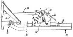
- FIG. 2is a perspective view of selected portions of an exhaust nozzle.
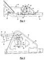
- FIG. 3is a perspective view of a first link having a curved slot.
- FIG. 4is a schematic view of the curved slot.
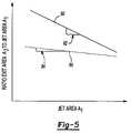
- FIG. 5is a graphic example of a benefit of using a curved slot according to the present invention.
- FIG. 1illustrates selected portions of a turbine engine assembly 10 that includes a compressor 12 , a combustor 14 , and a turbine 16 .
- the turbine engine assembly 10operates in a known manner, feeding compressed air from the compressor 12 to the combustor 14 .
- the compressed airis mixed with fuel and ignited to produce a flow of hot gasses 18 .
- the turbine 16transforms the flow of hot gasses 18 into mechanical energy to drive a compressor 12 .
- An exhaust nozzle 20directs the hot gasses 18 out of the engine assembly 10 to provide thrust for an aircraft.
- the exhaust nozzle 20includes first flaps 22 and second flaps 24 .
- the first flaps 22converge toward an engine central axis C and are pivotable along a direction D 1 to change the size of a jet area A 1 .
- the second flaps 24diverge from the engine central axis C and are moveable along a direction D 2 to change the size of an exit area A 2 .
- the first flaps 22pivot about a first hinge 26 and the second flaps 24 pivot about a second hinge 28 along the respective directions D 1 and D 2 .
- Actuators 30selectively pivot the first flaps 22 toward the engine central axis C to reduce the size of the jet area A 1 and outward relative to the engine central axis C to increase the size of the jet area A 1 .
- the second flaps 24move outward relative to the engine central axis C when the exhaust pressure of hot gases 18 is relatively high. Movement of the second flaps 24 outward increases the size of the exit area A 2 and movement of the second flaps 24 inward decreases the size of the exit area A 2 .
- the ratio between the size of the exit area A 2 and the size of the jet area A 1corresponds to the thrust that the turbine engine assembly 10 produces.
- the second flaps 24have a range of possible movement, represented by the ends of the direction arrow D 2 .
- the second flaps 24have a range of possible movement that is greater than previously known ranges, as will be described below.
- the greater range of motionprovides the advantage of a greater range of ratios between the size of the exit area A 2 and the size of the jet area A 1 .
- the greater range of ratiosallows greater control over thrust that the turbine engine assembly 10 produces.
- the second flap 24includes a flap portion 34 , a bracket 36 , and a link 40 .
- the bracket 36 and the flap portion 34are secured together with fasteners 38 .
- the bracket 36is coupled to the link 40 , which includes an end 42 that is fixed with a ball and socket joint 43 to a static structure 44 of the engine assembly 10 .
- a forward end 46 of the second flap 24is coupled at the second hinge 28 to the first flap 22 .
- a drive link 48is connected near the forward end 46 and is operatively linked to one of the actuators 30 ( FIG. 1 ) for selectively pivoting the first flap 22 to change the jet area A 1 .
- the bracket 36includes a bracket portion 58 that is secured to the flap portion 34 .
- the bracket portion 58is generally shaped to conform to the shape of the flap portion 34 .
- a surface 60extends from the bracket portion 58 .
- the surface 60is substantially perpendicular to the bracket portion 58 .
- the surface 60includes a curved channel portion 62 having a curved slot 64 .
- the curved slot 64includes a first end 66 and a second end 68 .
- the first end 66is positioned farther back in the engine assembly 10 than the second end 68 and is nearer to the flap portion 34 than the second end 68 . That is, the first end 66 is aft of the second end 68 .
- the link 40includes a strut 70 having one end fixed to the static structure 44 as described above.
- a slider 72is secured to the other end of the strut 70 .
- the slider 72is received into the curved slot 64 for guiding and stabilizing the second flap 24 .
- the bracket 36moves with the second flap 24 relative to strut 70 .
- the curved slot 64 and slider 72move relative to each other along the direction D.
- the strut 70 and slider 72allow the second flap 24 to move along the curved slot 64 between the first end 66 and the second end 68 .
- the first end 66 and the second end 68provide stops that prevent further movement of the slider 72 within the curved slot 64 to establish a range of possible movement of the second flap 24 .
- the position of the slider 72moves towards the first end 66 of the slot 64 when the second flap 24 hinges radially outward from the engine central axis C.
- the first end 66prevents further movement.
- the position of the slider 72moves towards the second end 68 of the curved slot 64 when the second flap 24 hinges radially inward toward the engine central axis C.
- the second end 68prevents further movement.
- the second flap 24has a range of possible positions between the first end 66 and the second end 68 .
- the strut 70extends along an axis represented by line 76 and forms an angle, G, with the line 78 , which is a reference line that is approximately parallel to the second flap 24 .
- the angle Gcorresponds to the range of the possible movement of the second flap 24 . That is, when the second flap 24 hinges radially inward toward the engine central axis C, the angle G decreases and when the second flap 24 hinges radially outward away from the engine central axis C, the angle G increases. It is desirable to maximize the range of the angle G to provide a greater range of movement of the second flap 24 . This increases the range of possible ratios between the size of the exit A 2 and the size of the jet area A 1 for greater control of the thrust that the turbine engine assembly 10 produces.
- the jet area A 1is relatively large such as when the first flaps 22 are outwardly positioned relative to the engine central axis C.
- the bracket 36moves such that the position of the slider 72 changes from the illustrated position near the second end 68 to a position near the first end 66 .
- a force associated with the movement of the slider 72is split into a first component along a line 79 that is tangent to the direction D of the curved slot 64 and a second component that is perpendicular to the line 79 (i.e., into a wall 80 of the curved slot 64 ).
- An engagement angle E between the axis 76 of the strut 70 and the tangent line 79corresponds to a relative proportion between the first component and second component of the force. Since the tangent line 79 is related to the curvature of the curved slot 64 , the relative proportion between the first component and the second component of the force varies non-linearly along the curved slot 64 .
- the engagement angle Enears 90°, more of the force of the slider 72 is directed into the wall 80 , which produces friction and resists movement of the slider 72 .
- frictional bindingoccurs when the strut forms an angle near 90° with the linear slot.
- the engagement angle Eremains above 90° due to the curvature of the curved slot 64 . That is, the curvature of the curved slot 64 effectively increases the engagement angle E compared to previously known assemblies. As a result, less of the force is toward the wall 80 and more of the force is in the direction D along the curved slot 64 , which allows the slider 72 to move relative to the curved slot 64 without frictionally binding.
- the curvature of the curved slot 64 from the first end 66 to the second end 68increases the engagement angle E such that frictional binding does not occur. This allows the second flap 24 to move closer to the engine central axis C than for the previously known linear slots, without frictional binding. That is, with previously known linear slots, when the corresponding engagement angle is near 90° the corresponding angle G is limited to a minimum of about 5° in order to avoid frictional binding. However, with the curved slot 64 , the engagement angle E is effectively increased by the amount of curvature of the curved slot 64 , which allows the angle G to be below 5° and therefore provides an increased range of possible movement of the second flap 24 and greater control over the thrust of the engine assembly 10 . It is to be understood that the angle G is one example reference from which the range of movement of the second flap can be determined and that, given this description, one of ordinary skill will recognize alternative reference axes or systems.
- the magnitude of curvature and length of the curved slot 64is selected to achieve a desired engagement angle E.
- the magnitude of curvatureis not too large because when the slider 72 position changes from the first end 66 to the second end 68 , the second component of the force into the wall 80 will become too large and result in frictional binding. Given this description, one of ordinary skill in the art will be able to recognize an appropriate magnitude of curvature to meet their particular needs.
- bracket 36is a separate component from the flap portion 34 , the type of material used for the bracket 36 can be selected to achieve desired bracket properties.
- the flap portion 34is made of a nickel-based material for high heat resistance and the bracket 36 is made of a titanium-based material for desired mechanical and frictional properties.
- FIG. 5illustrates graphically one example of a benefit of utilizing a curved slot 64 .
- line 90 for the curved slot 64represents a plot of a ratio of the exit area A 2 to the jet area A 1 versus the jet area A 1 in a “high mode” wherein the exhaust pressures are relatively high.
- the line 90includes a slope 92 that is significantly different than a slope 94 of a line 96 representing a previously known assembly having a linear slot.
- the larger slope 92 of the line 90 compared to the slope 94 of the line 96is the result of the larger range movement available using the curved slot 64 and corresponds to a greater advantage in engine efficiency compared to the previously known assemblies having linear slots.
Landscapes
- Engineering & Computer Science (AREA)
- Chemical & Material Sciences (AREA)
- Combustion & Propulsion (AREA)
- Mechanical Engineering (AREA)
- General Engineering & Computer Science (AREA)
- Supercharger (AREA)
- Control Of Turbines (AREA)
Abstract
Description
Claims (22)
Priority Applications (3)
| Application Number | Priority Date | Filing Date | Title |
|---|---|---|---|
| US11/200,895US7721550B2 (en) | 2005-08-10 | 2005-08-10 | Aircraft engine exhaust flap curved strut slot |
| EP06254095.0AEP1752648B1 (en) | 2005-08-10 | 2006-08-04 | Aircraft engine exhaust flap curved strut slot |
| JP2006212760AJP2007046601A (en) | 2005-08-10 | 2006-08-04 | Flap assembly for exhaust nozzle device, aircraft engine nozzle assembly, and method for adjusting size of exhaust outlet area of aircraft engine nozzle assembly |
Applications Claiming Priority (1)
| Application Number | Priority Date | Filing Date | Title |
|---|---|---|---|
| US11/200,895US7721550B2 (en) | 2005-08-10 | 2005-08-10 | Aircraft engine exhaust flap curved strut slot |
Publications (2)
| Publication Number | Publication Date |
|---|---|
| US20070033921A1 US20070033921A1 (en) | 2007-02-15 |
| US7721550B2true US7721550B2 (en) | 2010-05-25 |
Family
ID=37465109
Family Applications (1)
| Application Number | Title | Priority Date | Filing Date |
|---|---|---|---|
| US11/200,895Active2027-08-12US7721550B2 (en) | 2005-08-10 | 2005-08-10 | Aircraft engine exhaust flap curved strut slot |
Country Status (3)
| Country | Link |
|---|---|
| US (1) | US7721550B2 (en) |
| EP (1) | EP1752648B1 (en) |
| JP (1) | JP2007046601A (en) |
Cited By (2)
| Publication number | Priority date | Publication date | Assignee | Title |
|---|---|---|---|---|
| US20110088403A1 (en)* | 2007-08-21 | 2011-04-21 | United Technologies Corporation | Nozzle-area ratio float bias |
| US9856956B2 (en)* | 2015-01-20 | 2018-01-02 | United Technologies Corporation | Rod-and-bracket connector system for securing a pivoting member to a guide anchor moveably secured within a guide track |
Families Citing this family (3)
| Publication number | Priority date | Publication date | Assignee | Title |
|---|---|---|---|---|
| US7845176B2 (en)* | 2007-03-20 | 2010-12-07 | United Technologies Corporation | Mode strut and divergent flap interface |
| US8511098B2 (en)* | 2008-06-12 | 2013-08-20 | United Technologies Corporation | Slideable liner link assembly |
| FR2994711B1 (en)* | 2012-08-27 | 2014-08-08 | Aircelle Sa | ASSEMBLY FOR HOLDING THE INTERFACE OF A FRONT FRAME OF A NACELLE AND A TURBOJET CARTER |
Citations (11)
| Publication number | Priority date | Publication date | Assignee | Title |
|---|---|---|---|---|
| US3024600A (en)* | 1959-07-22 | 1962-03-13 | Curtiss Wright Corp | Exhaust nozzle actuator |
| US3558058A (en)* | 1969-03-14 | 1971-01-26 | Us Air Force | Thrust vectorable supersonic nozzle |
| JPS52140200A (en) | 1976-03-17 | 1977-11-22 | Rolls Royce | Variable area nozzle for gas turbine engine |
| JPS63253160A (en) | 1987-03-27 | 1988-10-20 | ユナイテッド・テクノロジーズ・コーポレイション | Method of positioning arc valve for exhaust nozzle and link device |
| JPH04504604A (en) | 1989-01-19 | 1992-08-13 | エム テー ウー モトーレン― ウント ツルビーネン―ウニオーン ミュンヘン ゲゼルシャフト ミット ベシュレンクテル ハフツング | propulsion nozzle |
| US5201800A (en)* | 1990-02-26 | 1993-04-13 | General Electric Company | Method for discharging combustion gases from an exhaust nozzle |
| US5221048A (en) | 1991-05-21 | 1993-06-22 | Lair Jean Pierre | Variable area exhaust nozzle |
| US5359851A (en) | 1992-11-25 | 1994-11-01 | Societe Nationale D'etude Et De Construction De Moteurs D'aviation (S.N.E.C.M.A.) | Variable geometry exhaust nozzle for a turbojet engine |
| US5813609A (en)* | 1996-12-11 | 1998-09-29 | General Electric Company | Hinged lined exhaust nozzle |
| JPH11182344A (en) | 1997-12-24 | 1999-07-06 | Ishikawajima Harima Heavy Ind Co Ltd | Multi-axis thrust deflection nozzle for gas turbine |
| GB2404222A (en)* | 2003-07-21 | 2005-01-26 | United Technologies Corp | Turbine engine nozzle |
Family Cites Families (5)
| Publication number | Priority date | Publication date | Assignee | Title |
|---|---|---|---|---|
| US2974477A (en)* | 1953-01-29 | 1961-03-14 | Gen Motors Corp | Variable jet nozzle and shroud |
| GB839230A (en) | 1956-01-12 | 1960-06-29 | Gen Motors Corp | Improvements relating to variable jet nozzles |
| US2874538A (en)* | 1957-03-22 | 1959-02-24 | Marquardt Aircraft Company | Thrust reverser for jet engine |
| US4361281A (en)* | 1980-07-07 | 1982-11-30 | General Electric Company | Exhaust nozzle |
| US4819876A (en)* | 1987-06-25 | 1989-04-11 | United Technologies Corporation | Divergent flap actuation system for a two-dimensional exhaust nozzle |
- 2005
- 2005-08-10USUS11/200,895patent/US7721550B2/enactiveActive
- 2006
- 2006-08-04EPEP06254095.0Apatent/EP1752648B1/ennot_activeCeased
- 2006-08-04JPJP2006212760Apatent/JP2007046601A/enactivePending
Patent Citations (12)
| Publication number | Priority date | Publication date | Assignee | Title |
|---|---|---|---|---|
| US3024600A (en)* | 1959-07-22 | 1962-03-13 | Curtiss Wright Corp | Exhaust nozzle actuator |
| US3558058A (en)* | 1969-03-14 | 1971-01-26 | Us Air Force | Thrust vectorable supersonic nozzle |
| JPS52140200A (en) | 1976-03-17 | 1977-11-22 | Rolls Royce | Variable area nozzle for gas turbine engine |
| JPS63253160A (en) | 1987-03-27 | 1988-10-20 | ユナイテッド・テクノロジーズ・コーポレイション | Method of positioning arc valve for exhaust nozzle and link device |
| JPH04504604A (en) | 1989-01-19 | 1992-08-13 | エム テー ウー モトーレン― ウント ツルビーネン―ウニオーン ミュンヘン ゲゼルシャフト ミット ベシュレンクテル ハフツング | propulsion nozzle |
| US5201800A (en)* | 1990-02-26 | 1993-04-13 | General Electric Company | Method for discharging combustion gases from an exhaust nozzle |
| US5221048A (en) | 1991-05-21 | 1993-06-22 | Lair Jean Pierre | Variable area exhaust nozzle |
| US5359851A (en) | 1992-11-25 | 1994-11-01 | Societe Nationale D'etude Et De Construction De Moteurs D'aviation (S.N.E.C.M.A.) | Variable geometry exhaust nozzle for a turbojet engine |
| US5813609A (en)* | 1996-12-11 | 1998-09-29 | General Electric Company | Hinged lined exhaust nozzle |
| JPH11182344A (en) | 1997-12-24 | 1999-07-06 | Ishikawajima Harima Heavy Ind Co Ltd | Multi-axis thrust deflection nozzle for gas turbine |
| GB2404222A (en)* | 2003-07-21 | 2005-01-26 | United Technologies Corp | Turbine engine nozzle |
| US7225622B2 (en)* | 2003-07-21 | 2007-06-05 | United Technologies Corporation | Turbine engine nozzle |
Cited By (3)
| Publication number | Priority date | Publication date | Assignee | Title |
|---|---|---|---|---|
| US20110088403A1 (en)* | 2007-08-21 | 2011-04-21 | United Technologies Corporation | Nozzle-area ratio float bias |
| US8733107B2 (en)* | 2007-08-21 | 2014-05-27 | United Technologies Corporation | Nozzle-area ratio float bias |
| US9856956B2 (en)* | 2015-01-20 | 2018-01-02 | United Technologies Corporation | Rod-and-bracket connector system for securing a pivoting member to a guide anchor moveably secured within a guide track |
Also Published As
| Publication number | Publication date |
|---|---|
| JP2007046601A (en) | 2007-02-22 |
| US20070033921A1 (en) | 2007-02-15 |
| EP1752648A2 (en) | 2007-02-14 |
| EP1752648B1 (en) | 2018-04-11 |
| EP1752648A3 (en) | 2010-07-21 |
Similar Documents
| Publication | Publication Date | Title |
|---|---|---|
| US7637095B2 (en) | Thrust vectorable fan variable area nozzle for a gas turbine engine fan nacelle | |
| US4176792A (en) | Variable area exhaust nozzle | |
| US8459035B2 (en) | Gas turbine engine with low fan pressure ratio | |
| US9194328B2 (en) | Fan variable area nozzle for a gas turbine engine fan nacelle with sliding actuation system | |
| US7845176B2 (en) | Mode strut and divergent flap interface | |
| US20110120078A1 (en) | Variable area fan nozzle track | |
| US4043509A (en) | Actuation system for a gas turbine engine exhaust device | |
| US8733107B2 (en) | Nozzle-area ratio float bias | |
| US10837403B2 (en) | Exhaust nozzle control including tapered control effector for a gas turbine engine | |
| EP1752648B1 (en) | Aircraft engine exhaust flap curved strut slot | |
| US8020386B2 (en) | Rollertrack pivoting axi-nozzle | |
| US11053887B2 (en) | Thrust reverser with displaceable trailing edge body | |
| US20120222398A1 (en) | Gas turbine engine with geared architecture | |
| US4000611A (en) | Variable area, load balancing nozzle | |
| EP4242444B1 (en) | Thrust reverser for variable area nozzle | |
| US5842643A (en) | Articulated exhaust nozzle fairing | |
| US20170145955A1 (en) | Hybrid exhaust nozzle | |
| EP1995442B1 (en) | Turbine engine valve assembly | |
| EP1916405A2 (en) | Thrust vectorable fan variable area nozzle for a gas turbine engine fan nacelle | |
| US5207787A (en) | Variable area nozzle | |
| US9840984B2 (en) | Linkage to control and restrain flap movement | |
| US6185926B1 (en) | Turbojet engine thrust reverser and exhaust nozzle assembly |
Legal Events
| Date | Code | Title | Description |
|---|---|---|---|
| AS | Assignment | Owner name:UNITED TECHNOLOGIES CORPORATION,CONNECTICUT Free format text:ASSIGNMENT OF ASSIGNORS INTEREST;ASSIGNOR:PETERS, DONALD W.;REEL/FRAME:016877/0285 Effective date:20050810 Owner name:UNITED TECHNOLOGIES CORPORATION, CONNECTICUT Free format text:ASSIGNMENT OF ASSIGNORS INTEREST;ASSIGNOR:PETERS, DONALD W.;REEL/FRAME:016877/0285 Effective date:20050810 | |
| STCF | Information on status: patent grant | Free format text:PATENTED CASE | |
| FPAY | Fee payment | Year of fee payment:4 | |
| MAFP | Maintenance fee payment | Free format text:PAYMENT OF MAINTENANCE FEE, 8TH YEAR, LARGE ENTITY (ORIGINAL EVENT CODE: M1552) Year of fee payment:8 | |
| AS | Assignment | Owner name:RAYTHEON TECHNOLOGIES CORPORATION, MASSACHUSETTS Free format text:CHANGE OF NAME;ASSIGNOR:UNITED TECHNOLOGIES CORPORATION;REEL/FRAME:054062/0001 Effective date:20200403 | |
| AS | Assignment | Owner name:RAYTHEON TECHNOLOGIES CORPORATION, CONNECTICUT Free format text:CORRECTIVE ASSIGNMENT TO CORRECT THE AND REMOVE PATENT APPLICATION NUMBER 11886281 AND ADD PATENT APPLICATION NUMBER 14846874. TO CORRECT THE RECEIVING PARTY ADDRESS PREVIOUSLY RECORDED AT REEL: 054062 FRAME: 0001. ASSIGNOR(S) HEREBY CONFIRMS THE CHANGE OF ADDRESS;ASSIGNOR:UNITED TECHNOLOGIES CORPORATION;REEL/FRAME:055659/0001 Effective date:20200403 | |
| MAFP | Maintenance fee payment | Free format text:PAYMENT OF MAINTENANCE FEE, 12TH YEAR, LARGE ENTITY (ORIGINAL EVENT CODE: M1553); ENTITY STATUS OF PATENT OWNER: LARGE ENTITY Year of fee payment:12 | |
| AS | Assignment | Owner name:RTX CORPORATION, CONNECTICUT Free format text:CHANGE OF NAME;ASSIGNOR:RAYTHEON TECHNOLOGIES CORPORATION;REEL/FRAME:064714/0001 Effective date:20230714 |