US7720532B2 - Clean margin assessment tool - Google Patents
Clean margin assessment toolDownload PDFInfo
- Publication number
- US7720532B2 US7720532B2US10/558,831US55883105AUS7720532B2US 7720532 B2US7720532 B2US 7720532B2US 55883105 AUS55883105 AUS 55883105AUS 7720532 B2US7720532 B2US 7720532B2
- Authority
- US
- United States
- Prior art keywords
- tissue
- sensor
- type
- distance
- integrated tool
- Prior art date
- Legal status (The legal status is an assumption and is not a legal conclusion. Google has not performed a legal analysis and makes no representation as to the accuracy of the status listed.)
- Active, expires
Links
Images


Classifications
- A—HUMAN NECESSITIES
- A61—MEDICAL OR VETERINARY SCIENCE; HYGIENE
- A61B—DIAGNOSIS; SURGERY; IDENTIFICATION
- A61B5/00—Measuring for diagnostic purposes; Identification of persons
- A61B5/41—Detecting, measuring or recording for evaluating the immune or lymphatic systems
- A61B5/414—Evaluating particular organs or parts of the immune or lymphatic systems
- A61B5/415—Evaluating particular organs or parts of the immune or lymphatic systems the glands, e.g. tonsils, adenoids or thymus
- A—HUMAN NECESSITIES
- A61—MEDICAL OR VETERINARY SCIENCE; HYGIENE
- A61B—DIAGNOSIS; SURGERY; IDENTIFICATION
- A61B18/00—Surgical instruments, devices or methods for transferring non-mechanical forms of energy to or from the body
- A61B18/04—Surgical instruments, devices or methods for transferring non-mechanical forms of energy to or from the body by heating
- A61B18/08—Surgical instruments, devices or methods for transferring non-mechanical forms of energy to or from the body by heating by means of electrically-heated probes
- A61B18/082—Probes or electrodes therefor
- A—HUMAN NECESSITIES
- A61—MEDICAL OR VETERINARY SCIENCE; HYGIENE
- A61B—DIAGNOSIS; SURGERY; IDENTIFICATION
- A61B34/00—Computer-aided surgery; Manipulators or robots specially adapted for use in surgery
- A61B34/20—Surgical navigation systems; Devices for tracking or guiding surgical instruments, e.g. for frameless stereotaxis
- A—HUMAN NECESSITIES
- A61—MEDICAL OR VETERINARY SCIENCE; HYGIENE
- A61B—DIAGNOSIS; SURGERY; IDENTIFICATION
- A61B5/00—Measuring for diagnostic purposes; Identification of persons
- A61B5/0059—Measuring for diagnostic purposes; Identification of persons using light, e.g. diagnosis by transillumination, diascopy, fluorescence
- A61B5/0082—Measuring for diagnostic purposes; Identification of persons using light, e.g. diagnosis by transillumination, diascopy, fluorescence adapted for particular medical purposes
- A61B5/0084—Measuring for diagnostic purposes; Identification of persons using light, e.g. diagnosis by transillumination, diascopy, fluorescence adapted for particular medical purposes for introduction into the body, e.g. by catheters
- A—HUMAN NECESSITIES
- A61—MEDICAL OR VETERINARY SCIENCE; HYGIENE
- A61B—DIAGNOSIS; SURGERY; IDENTIFICATION
- A61B5/00—Measuring for diagnostic purposes; Identification of persons
- A61B5/0059—Measuring for diagnostic purposes; Identification of persons using light, e.g. diagnosis by transillumination, diascopy, fluorescence
- A61B5/0082—Measuring for diagnostic purposes; Identification of persons using light, e.g. diagnosis by transillumination, diascopy, fluorescence adapted for particular medical purposes
- A61B5/0091—Measuring for diagnostic purposes; Identification of persons using light, e.g. diagnosis by transillumination, diascopy, fluorescence adapted for particular medical purposes for mammography
- A—HUMAN NECESSITIES
- A61—MEDICAL OR VETERINARY SCIENCE; HYGIENE
- A61B—DIAGNOSIS; SURGERY; IDENTIFICATION
- A61B5/00—Measuring for diagnostic purposes; Identification of persons
- A61B5/01—Measuring temperature of body parts ; Diagnostic temperature sensing, e.g. for malignant or inflamed tissue
- A—HUMAN NECESSITIES
- A61—MEDICAL OR VETERINARY SCIENCE; HYGIENE
- A61B—DIAGNOSIS; SURGERY; IDENTIFICATION
- A61B5/00—Measuring for diagnostic purposes; Identification of persons
- A61B5/05—Detecting, measuring or recording for diagnosis by means of electric currents or magnetic fields; Measuring using microwaves or radio waves
- A61B5/0507—Detecting, measuring or recording for diagnosis by means of electric currents or magnetic fields; Measuring using microwaves or radio waves using microwaves or terahertz waves
- A—HUMAN NECESSITIES
- A61—MEDICAL OR VETERINARY SCIENCE; HYGIENE
- A61B—DIAGNOSIS; SURGERY; IDENTIFICATION
- A61B5/00—Measuring for diagnostic purposes; Identification of persons
- A61B5/43—Detecting, measuring or recording for evaluating the reproductive systems
- A61B5/4306—Detecting, measuring or recording for evaluating the reproductive systems for evaluating the female reproductive systems, e.g. gynaecological evaluations
- A61B5/4312—Breast evaluation or disorder diagnosis
- A—HUMAN NECESSITIES
- A61—MEDICAL OR VETERINARY SCIENCE; HYGIENE
- A61B—DIAGNOSIS; SURGERY; IDENTIFICATION
- A61B8/00—Diagnosis using ultrasonic, sonic or infrasonic waves
- A61B8/08—Clinical applications
- A61B8/0858—Clinical applications involving measuring tissue layers, e.g. skin, interfaces
- A—HUMAN NECESSITIES
- A61—MEDICAL OR VETERINARY SCIENCE; HYGIENE
- A61B—DIAGNOSIS; SURGERY; IDENTIFICATION
- A61B8/00—Diagnosis using ultrasonic, sonic or infrasonic waves
- A61B8/42—Details of probe positioning or probe attachment to the patient
- A61B8/4245—Details of probe positioning or probe attachment to the patient involving determining the position of the probe, e.g. with respect to an external reference frame or to the patient
- A—HUMAN NECESSITIES
- A61—MEDICAL OR VETERINARY SCIENCE; HYGIENE
- A61B—DIAGNOSIS; SURGERY; IDENTIFICATION
- A61B17/00—Surgical instruments, devices or methods
- A61B2017/00017—Electrical control of surgical instruments
- A61B2017/00022—Sensing or detecting at the treatment site
- A61B2017/00026—Conductivity or impedance, e.g. of tissue
- A—HUMAN NECESSITIES
- A61—MEDICAL OR VETERINARY SCIENCE; HYGIENE
- A61B—DIAGNOSIS; SURGERY; IDENTIFICATION
- A61B34/00—Computer-aided surgery; Manipulators or robots specially adapted for use in surgery
- A61B34/10—Computer-aided planning, simulation or modelling of surgical operations
- A61B2034/107—Visualisation of planned trajectories or target regions
- A—HUMAN NECESSITIES
- A61—MEDICAL OR VETERINARY SCIENCE; HYGIENE
- A61B—DIAGNOSIS; SURGERY; IDENTIFICATION
- A61B34/00—Computer-aided surgery; Manipulators or robots specially adapted for use in surgery
- A61B34/20—Surgical navigation systems; Devices for tracking or guiding surgical instruments, e.g. for frameless stereotaxis
- A61B2034/2046—Tracking techniques
- A61B2034/2051—Electromagnetic tracking systems
- A—HUMAN NECESSITIES
- A61—MEDICAL OR VETERINARY SCIENCE; HYGIENE
- A61B—DIAGNOSIS; SURGERY; IDENTIFICATION
- A61B34/00—Computer-aided surgery; Manipulators or robots specially adapted for use in surgery
- A61B34/20—Surgical navigation systems; Devices for tracking or guiding surgical instruments, e.g. for frameless stereotaxis
- A61B2034/2046—Tracking techniques
- A61B2034/2055—Optical tracking systems
- A—HUMAN NECESSITIES
- A61—MEDICAL OR VETERINARY SCIENCE; HYGIENE
- A61B—DIAGNOSIS; SURGERY; IDENTIFICATION
- A61B90/00—Instruments, implements or accessories specially adapted for surgery or diagnosis and not covered by any of the groups A61B1/00 - A61B50/00, e.g. for luxation treatment or for protecting wound edges
- A61B90/06—Measuring instruments not otherwise provided for
- A61B2090/061—Measuring instruments not otherwise provided for for measuring dimensions, e.g. length
- A—HUMAN NECESSITIES
- A61—MEDICAL OR VETERINARY SCIENCE; HYGIENE
- A61B—DIAGNOSIS; SURGERY; IDENTIFICATION
- A61B90/00—Instruments, implements or accessories specially adapted for surgery or diagnosis and not covered by any of the groups A61B1/00 - A61B50/00, e.g. for luxation treatment or for protecting wound edges
- A61B90/36—Image-producing devices or illumination devices not otherwise provided for
- A61B2090/364—Correlation of different images or relation of image positions in respect to the body
- A61B2090/367—Correlation of different images or relation of image positions in respect to the body creating a 3D dataset from 2D images using position information
- A—HUMAN NECESSITIES
- A61—MEDICAL OR VETERINARY SCIENCE; HYGIENE
- A61B—DIAGNOSIS; SURGERY; IDENTIFICATION
- A61B90/00—Instruments, implements or accessories specially adapted for surgery or diagnosis and not covered by any of the groups A61B1/00 - A61B50/00, e.g. for luxation treatment or for protecting wound edges
- A61B90/36—Image-producing devices or illumination devices not otherwise provided for
- A61B90/37—Surgical systems with images on a monitor during operation
- A61B2090/378—Surgical systems with images on a monitor during operation using ultrasound
- A—HUMAN NECESSITIES
- A61—MEDICAL OR VETERINARY SCIENCE; HYGIENE
- A61B—DIAGNOSIS; SURGERY; IDENTIFICATION
- A61B5/00—Measuring for diagnostic purposes; Identification of persons
- A61B5/0059—Measuring for diagnostic purposes; Identification of persons using light, e.g. diagnosis by transillumination, diascopy, fluorescence
- A61B5/0071—Measuring for diagnostic purposes; Identification of persons using light, e.g. diagnosis by transillumination, diascopy, fluorescence by measuring fluorescence emission
- A—HUMAN NECESSITIES
- A61—MEDICAL OR VETERINARY SCIENCE; HYGIENE
- A61B—DIAGNOSIS; SURGERY; IDENTIFICATION
- A61B5/00—Measuring for diagnostic purposes; Identification of persons
- A61B5/0059—Measuring for diagnostic purposes; Identification of persons using light, e.g. diagnosis by transillumination, diascopy, fluorescence
- A61B5/0075—Measuring for diagnostic purposes; Identification of persons using light, e.g. diagnosis by transillumination, diascopy, fluorescence by spectroscopy, i.e. measuring spectra, e.g. Raman spectroscopy, infrared absorption spectroscopy
- A—HUMAN NECESSITIES
- A61—MEDICAL OR VETERINARY SCIENCE; HYGIENE
- A61B—DIAGNOSIS; SURGERY; IDENTIFICATION
- A61B5/00—Measuring for diagnostic purposes; Identification of persons
- A61B5/0059—Measuring for diagnostic purposes; Identification of persons using light, e.g. diagnosis by transillumination, diascopy, fluorescence
- A61B5/0082—Measuring for diagnostic purposes; Identification of persons using light, e.g. diagnosis by transillumination, diascopy, fluorescence adapted for particular medical purposes
- A61B5/0084—Measuring for diagnostic purposes; Identification of persons using light, e.g. diagnosis by transillumination, diascopy, fluorescence adapted for particular medical purposes for introduction into the body, e.g. by catheters
- A61B5/0086—Measuring for diagnostic purposes; Identification of persons using light, e.g. diagnosis by transillumination, diascopy, fluorescence adapted for particular medical purposes for introduction into the body, e.g. by catheters using infrared radiation
- A—HUMAN NECESSITIES
- A61—MEDICAL OR VETERINARY SCIENCE; HYGIENE
- A61B—DIAGNOSIS; SURGERY; IDENTIFICATION
- A61B5/00—Measuring for diagnostic purposes; Identification of persons
- A61B5/01—Measuring temperature of body parts ; Diagnostic temperature sensing, e.g. for malignant or inflamed tissue
- A61B5/015—By temperature mapping of body part
- A—HUMAN NECESSITIES
- A61—MEDICAL OR VETERINARY SCIENCE; HYGIENE
- A61B—DIAGNOSIS; SURGERY; IDENTIFICATION
- A61B5/00—Measuring for diagnostic purposes; Identification of persons
- A61B5/05—Detecting, measuring or recording for diagnosis by means of electric currents or magnetic fields; Measuring using microwaves or radio waves
- A61B5/053—Measuring electrical impedance or conductance of a portion of the body
- A—HUMAN NECESSITIES
- A61—MEDICAL OR VETERINARY SCIENCE; HYGIENE
- A61B—DIAGNOSIS; SURGERY; IDENTIFICATION
- A61B5/00—Measuring for diagnostic purposes; Identification of persons
- A61B5/05—Detecting, measuring or recording for diagnosis by means of electric currents or magnetic fields; Measuring using microwaves or radio waves
- A61B5/055—Detecting, measuring or recording for diagnosis by means of electric currents or magnetic fields; Measuring using microwaves or radio waves involving electronic [EMR] or nuclear [NMR] magnetic resonance, e.g. magnetic resonance imaging
- A—HUMAN NECESSITIES
- A61—MEDICAL OR VETERINARY SCIENCE; HYGIENE
- A61B—DIAGNOSIS; SURGERY; IDENTIFICATION
- A61B5/00—Measuring for diagnostic purposes; Identification of persons
- A61B5/06—Devices, other than using radiation, for detecting or locating foreign bodies ; Determining position of diagnostic devices within or on the body of the patient
- A—HUMAN NECESSITIES
- A61—MEDICAL OR VETERINARY SCIENCE; HYGIENE
- A61B—DIAGNOSIS; SURGERY; IDENTIFICATION
- A61B8/00—Diagnosis using ultrasonic, sonic or infrasonic waves
- A61B8/12—Diagnosis using ultrasonic, sonic or infrasonic waves in body cavities or body tracts, e.g. by using catheters
- A—HUMAN NECESSITIES
- A61—MEDICAL OR VETERINARY SCIENCE; HYGIENE
- A61B—DIAGNOSIS; SURGERY; IDENTIFICATION
- A61B8/00—Diagnosis using ultrasonic, sonic or infrasonic waves
- A61B8/44—Constructional features of the ultrasonic, sonic or infrasonic diagnostic device
- A61B8/4444—Constructional features of the ultrasonic, sonic or infrasonic diagnostic device related to the probe
- A61B8/4472—Wireless probes
Definitions
- the present inventionrelates generally, to a medical tool for tissue characterization, and specifically, to an integrated tool, having a tissue-type sensor, for determining the tissue type at an incision edge, and a distance-measuring sensor, for determining the distance to an interface with another tissue type.
- the toolis operable for confirming an existence of a clean margin of healthy tissue around an excised tumor, and for determining the width of the margin.
- breast conserving therapyis indicated for patients with Stage T1 or T2 cancers, of between less then about 0.5 and about 5 cm in greatest dimension.
- a radiologistmay place a guide wire under x-ray or ultrasound guidance, so that the proximal tip of the guide wire, with respect to the tissue, is in the tumor.
- an imaging modalityalone, for example, mammography, CT, ultrasound, or another imaging modality may be used to locate the tumor.
- the patientis then transported to the operating room, where the surgeon uses the guide wire, or the image, or palpation to locate the tumor in the breast and to excise a portion of tissue including the cancerous portion and a layer of healthy tissue surrounding the cancerous portion.
- the layer of healthy tissuemust enclose the cancerous portion, to ensure that all the malignancy has been removed.
- This layeris often referred to as a “clean margin.”
- a desired depth of the clean marginmay range from 1 cell layer, or about 40 microns, to 10 mm.
- the surgeonuses a scalpel and (or) an electrosurgical cutting device to remove a tissue portion enclosing the tumor, in one piece, and manage bleeding.
- the removed portionis transported to the pathologist, who samples the margins, histologically, at specific and suspicious points, for example, at one or a few representative points on each face of the portion, to assess whether the cancer has been completely removed from the body. If the pathologists deems that cancer cells are too close to the edge of the portion, i.e., if he deems the margin infected, a re-excision is recommended, and the patient must undergo a second surgical procedure to remove more of the tissue.
- U.S. Pat. No. 6,546,787 to Schiller et al.whose disclosure is incorporated herein by reference, provides an apparatus and method for detecting a distance from a tissue edge to a malignant tissue, enclosed therein.
- the apparatuscomprises a needle having a strain gage, mounted on one of the needles walls. Strain signals are collected as the needle is moved through the tissue. The needle is inserted at different points to allow data collection from different points within the tissue. The data is sent together with its spatial coordinates to a computerized system, which provides an image of the structure of the examined tissue.
- WO Patent 9712553 to Changus et al.whose disclosures is incorporated herein by reference, provides an apparatus for marking a predetermined margin around a tumor that is contained within a healthy tissue.
- the apparatusincludes a needle to be inserted into the patient's body towards the malignant tissue.
- the needlecontains margin wires that are to create a cage containing the malignant tissue within it.
- the needleis to reach a predetermined distance of between 7 and 13 mm and preferably 10 mm from the malignant tissue before the wires are deployed to create the cage.
- the cageis then used to guide the surgeon performing a lumpectomy procedure, as to the portion of tissue to be excised and its location, so that the removed tissue will include the malignant tissue with a sufficient clean margin around it.
- the drawback of such a procedureis that it requires exact knowledge as to the location of the malignant tissue and its boundaries while creating the cage.
- the locator element pathpreferably encompasses the distal-most portion of the tissue volume, with respect to the tool, without penetrating that volume.
- Multiple locator elementsmay be deployed to further define the tissue volume along additional paths defining the tissue volume border that do not penetrate the volume.
- Other localization wire embodiments of the inventionare disclosed in which the tissue volume may be penetrated by a portion of the device.
- Polar and tangential deployment configurations as well as a locator element that may be cold-formed by a die in the distal portion of the deployment tube into a permanent accurate shapeare also disclosed.
- the apparatuscomprises a biopsy instrument having a distal end (with respect to operator) adapted for entry into the patient's body, a longitudinal shaft, and a cutting element disposed along the shaft. The cutting element is actuatable between a radially retracted and extended position.
- the instrumentis rotatable about its axis in the radially extended position to isolate a desired tissue specimen from surrounding tissue by defining a peripheral margin about the tissue specimen.
- tissue specimenOnce the tissue specimen is isolated, it may be segmented by further manipulation of the cutting element, after which the tissue segments are preferably individually removed from the patient's body through a cannula or the like.
- the specimenmay be encapsulated and removed as an intact piece.
- U.S. Pat. No. 6,840,948 to Albrecht et aldiscloses a device and method for removal of tissue lesions, for example, in the breast, the liver and the lungs.
- the deviceincludes a probe housing having a rotatable RF loop cutter mounted at the distal end of the probe.
- the RF loop cuttercan include at least one electrode supplied with an RF actuating signal for cutting tissue.
- a rotational drive and specimen containment sheathcan also be included.
- Real-time imagingis preferably used with the RF loop probe to assist in placement of the probe, and to more accurately assess a desired excision volume.
- Ultrasound or ultrasonographyis a medical imaging technique, using high frequency sound waves in the range of about 1 to 20 MHz and their echoes.
- the sound wavestravel in the body and are reflected by interfaces between different types of tissues, such as between a healthy tissue and a denser cancerous tissue, or between a soft tissue and a bone.
- the ultrasound probereceives the reflected sound waves and the associated instrumentation calculates the distances from the probe to the reflecting boundaries.
- Ultrasound probesare formed of piezoelectric crystal, which produces an electric signal in response to a pressure pulse.
- the shape of the probedetermines its field of view, and the frequency of the emitted sound determines the minimal detectable object size.
- the probesare designed to move across the surface of the body.
- some probesare designed to be inserted through body. lumens, such as the vagina or the rectum, so as to get closer to the organ being examined.
- the calculation of the distance, dis based on the speed of sound in the tissue, v, (for example, in fat 1450 m/s, in blood 1570 m/s, in skull bone 4080 m/s, while the mean value for human soft tissue is 1540 m/s, which is similar to that of water) and the time of travel, t, usually measured in microseconds.
- vthe speed of sound in the tissue
- tthe time of travel
- a predetermined offsetneeds to be considered, due to fixed electronic and mechanical delays.
- the offsetcompensates for transit time of the sound pulse through the transducer's wear-plate and the couplant layer, and for any electronic switching time or cable delays.
- the offsetis determined as a part of instrument calibration procedures and is necessary for high accuracy. It will be further appreciated that when a single transducer transmits and receives, there is an additional dead time, which can be overcome by using at least two transducers, one transmitting and the other receiving.
- a reflectance, Rmay be defined, representing the energy that is being reflected.
- Z 1is the acoustic impedance of the tissue in which the ultrasound pulse travels
- Z 2is the impedance of the tissue across the interface.
- the reflectancedepends on the variation in tissue density ⁇ 1 and ⁇ 2 , across the interface.
- the ultrasound techniqueis useful in identifying cancerous tumors.
- a radiologistmay use the ultrasound imaging to guide a surgical tool, such as a biopsy needle or an incision instrument.
- a development of recent yearsis a 3D ultrasound imaging, in which, several two-dimensional images are acquired by moving the probes across the body surface or by rotating probes, inserted into body lumens. The two-dimensional scans are then combined by specialized computer software to form 3D images.
- each elementhas a dedicated electric circuit, so that the beam can be “steered” by changing the timing in which each element sends out a pulse.
- transducer-pulse controlsallow the operator to set and change the frequency and duration of the ultrasound pulses, as well as the scan mode of the machine.
- a probe formed of array transducershas the ability to be steered as well as focused. By sequentially stimulating each element, the beams can be rapidly steered from the left to right, to produce a two-dimensional cross sectional image.
- Contrast agentsmay be used in conjunction with ultrasound imaging, for example as taught by U.S. Pat. No. 6,280,704, to Schutt, et al., entitled, “Ultrasonic imaging system utilizing a long-persistence contrast agent,” whose disclosure is incorporated herein by reference.
- tissue characterizationA large number of techniques, other than ultrasound, are available today for tissue characterization, to determine the presence of abnormal tissue, for example, cancerous or pre-cancerous tissue. Many of these may be used with hand-held probes. Others use miniature probes that may be inserted into a body lumen or applied in minimally invasive surgery.
- tissue characterizationis based on measurements of the tissue's electro-magnetic properties.
- the methodincludes applying an electrical pulse to the tissue to be examined via a probe formed with an open cavity such that the probe generates an electrical fringe field in examined tissue within the cavity and produces a reflected electrical pulse therefrom with negligible radiation penetrating into other tissues or biological bodies near the examined tissue; detecting the reflected electrical pulse; and comparing electrical characteristics of the reflected electrical pulse with respect to the applied electrical pulse to provide an indication of the dielectric properties of the examined tissue.
- U.S. Patent Application 60/641,081entitled, “Device and Method for Tissue Characterization in a Body Lumen, by an Endoscopic Electromagnetic Probe,” whose disclosure is incorporated herein by reference, discloses a device and method for tissue characterization in a body lumen, for the detection of abnormalities, using an electromagnetic probe, mounted on an endoscope.
- the endoscopemay be designed for insertion in a body lumen, selected from the group consisting of an oral cavity, a gastrointestinal tract, a rectum, a colon, bronchi, a vagina, a cervix, a urinary tract, and blood vessels. Additionally, it may be designed for insertion in a gagar valve.
- Electrical impedance imagingis another known imaging technique for detecting tumors. It involves systems in which the impedance between a point on the surface of the skin and some reference point on the body of a patient is determined. Sometimes, a multi-element probe, formed as a sheet with an array of electrical contacts is used, for obtaining a two-dimensional impedance map of the tissue, for example, the breast. The two-dimensional impedance map may be used, possibly in conjunction with other data, such as mammography, for the detection of cancer.
- Rajshekhar, V.(“Continuous impedance monitoring during CT-guided stereotactic surgery: relative value in cystic and solid lesions,” Rajshekhar, V., British Journal of Neurosurgery, 1992, 6, 439-444) describes using an impedance probe with a single electrode to measure the impedance characteristics of lesions.
- the objective of the studywas to use the measurements made in the lesions to determine the extent of the lesions and to localize the lesions more accurately.
- the probewas guided to the tumor by CT and four measurements were made within the lesion as the probe passed through the lesion.
- a biopsy of the lesionwas performed using the outer sheath of the probe as a guide to position, after the probe itself was withdrawn.
- U.S. Pat. No. 4,458,694, to Sollish, et al., entitled, “Apparatus and method for detection of tumors in tissue,” whose disclosure is incorporated herein by reference,relates to an apparatus for detecting tumors in human breast, based on the dielectric constants of localized regions of the breast tissue.
- the apparatusincludes a probe, comprising a plurality of elements.
- the apparatusfurther includes means for applying an AC signal to the tissue, means for sensing electrical properties at each of the probe elements at different times, and signal processing circuitry, coupled to the sensing means, for comparing the electrical properties sensed at the different times.
- the apparatusthus provides an output of the dielectric constants of localized regions of breast tissue associated with the probe.
- U.S. Pat. No. 4,291,708 to Frei, et al.entitled, “Apparatus and method for detection of tumors in tissue,” whose disclosure is incorporated herein by reference, relates to apparatus for detecting tumors in human breast tissue, by the dielectric constants of a plurality of localized regions of human breast tissue.
- the devicecomprises: means for providing a polychromic emmitance map of a portion of the body; means for determining a plurality of polychromic measures from one or both of a portion of the body; and a display of an indication based on said plurality of polychromic measures.
- tissue characterizationis by optical fluorescence spectroscopy.
- a sample of large moleculesWhen a sample of large molecules is irradiated, for example, by laser light, it will absorb radiation, and various levels will be excited. Some of the excited states will return back substantially to the previous state, by elastic scattering, and some energy will be lost in internal conversion, collisions and other loss mechanisms. However, some excited states will create fluorescent radiation, which, due to the distribution of states, will give a characteristic wavelength distribution.
- HPDhematoporphyrin derivatives
- DHEdihematoporphyrin ether/ester
- HPhematoporphyrin
- PHEpolyhematoporphyrin ester
- TSPCtetrasulfonated phthalocyanine
- U.S. Pat. No. 5,115,137to Andersson-Engels, et al, entitled, “Diagnosis by means of fluorescent light emission from tissue,” whose disclosure is incorporated herein by reference, relates to improved detection of properties of tissue by means of induced fluorescence of large molecules. The tissue character may then be evaluated from the observed large-molecule spectra. According to U.S. Pat. No. 5,115,137, the spectrum for tonsil cancer is clearly different from normal mucosa, due to endogenous porphyrins.
- Optical fibersdirect low power light energy at a section of tissue to be ablated to cause the section to fluoresce.
- the fluorescence patternis analyzed to determine whether the fluorescence frequency spectrum is representative of normal or abnormal tissue.
- a source of high power, ultraviolet, laser energy directed through an optical fiber at the section of tissueis fired only when the fluorometric analysis indicates that it is directed at abnormal tissue.
- the methodincludes initially administering to the patient a non-toxic atheroma-enhancing reagent which causes the plaque to have a characteristic optical property when illuminated with a given radiation, introducing a catheter system including fiberoptic cable means into the artery such that the distal end thereof is operatively opposite the plaque site, introducing into the proximal end of the fiberoptic cable means the given radiation, photoelectrically sensing at the proximal end the characteristic optical property to generate a control signal, and directly under the control of the control signal transmitting via the cable means from the proximal end to the distal end, periodically occurring laser pulses until the characteristic optical property is no longer sensed.
- the method of the aforementioned patentmay comprise illuminating a tissue sample with electromagnetic radiation wavelengths of about 337 nm, 380 nm and 460 nm, to produce fluorescence; detecting a plurality of discrete emission wavelengths from the fluorescence; and calculating from the emission wavelengths a probability that the tissue sample belongs in particular tissue classification.
- energy pulsesare applied to the examined tissue, and the changes in impedance and/or the optical characteristics produced by the applied energy pulses are detected and utilized for determining the presence of the target cells in the examined tissue.
- the applied energy pulsesinclude laser pulses, and the physical element conjugated with a biological carrier is a light-sensitive semiconductor having impedance which substantially decrease in the presence of light.
- the same probe used for detecting the targeted cellsmay also be used for destroying the cells so targeted.
- Optical reflectance spectroscopymay also be used. Its application for tissue characterization is described, for example, in http://www.sbsplimb.nichd.nih.gov/html/spectroscopy.html, downloaded on Mar. 15, 2005. It describes an optical reflectance spectroscopy (ORS) device for measuring the thickness of the epithelial layer, and an evaluation technique based on oblique angle reflectance spectroscopy that allows assessment of the scattering and absorption properties of the epithelium and stroma, thus providing information on chronic oral epithelial tissue inflammation, which is considered a potential diagnostic precursor to oral cancer.
- ORSoptical reflectance spectroscopy
- MRImagnetic resonance imaging
- Conventional MRIis a large-apparatus, for whole body imaging, having:
- an RF coilfor producing the B 1 magnetic field, necessary to rotate the spins by 90° or 180° and for detecting the MRI signal;
- a computerfor controlling the components of the MRI imager.
- the magnetis a large horizontal bore superconducting magnet, which provides a homogeneous magnetic field in an internal region within the magnet.
- a patient or object to be imagedis usually positioned in the homogeneous field region located in the central air gap for imaging.
- a typical gradient coil systemcomprises an anti-Helmholtz type of coil. These are two parallel ring shaped coils, around the z axis. Current in each of the two coils flows in opposite directions creating a magnetic field gradient between the two coils.
- the RF coilcreates a B1 field, which rotates the net magnetization in a pulse sequence.
- the RF coilsmay be: 1) transmit and receive coils, 2) receive only coils, and 3) transmit only coils.
- the MRIrelies on a magnetic field in an internal region within the magnet. As such, it is unsuitable as a handheld probe or an endoscopic probe, because the tissue to be imaged has to be in the internal region of the imager,
- the probecomprises (i) a miniature primary magnet having a longitudinal axis and an external surface extending in the axial direction, and (ii) a RF coil surrounding and proximal to said surface.
- the primary magnetis structured and configured to provide a symmetrical, preferably cylindrically shaped, homogeneous field region external to the surface of the magnet.
- the RF coilreceives NMR signals from excited nuclei.
- one or more gradient coilsare provided to spatially encode the nuclear spins of nuclei excited by an RF coil, which may be the same coil used for receiving NMR signals or another RF coil.
- Contrast agentsmay be used in conjunction with MRI.
- U.S. Pat. No. 6,315,981 to Ungerentitled, “Gas filled microspheres as magnetic resonance imaging contrast agents,” whose disclosure is incorporated herein by reference, describes the use of gas filled microspheres as contrast agents for MRI.
- Temperature imaging for locating and detecting neoplastic tissueis also known.
- the surface temperature of skin in the area of a malignant tumorexhibited a higher temperature than that expected of healthy tissue.
- contact thermometrybecame a reality along with its use in medical applications.
- Devices employing contact thermometrycould sense and display temperature changes through indicators which changed colors, either permanently or temporarily, when placed in direct physical contact with a surface such as skin, reflecting a temperature at or near the point of contact. An abnormal reading would alert a user to the need for closer, more detailed examination of the region in question.
- U.S. Pat. No. 6,135,968, to Brounsteinentitled, “Differential temperature measuring device and method”, whose disclosure is incorporated herein by reference, describes a device and method for sensing temperatures at internal body locations non-surgically accessible only through body orifices.
- the deviceis particularly useful in medical applications such as screening for cancer and other abnormal biological activity signaled by an increase in temperature at a selected site.
- the deviceis temporarily, adhesively affixed to a user's fingertip or to a mechanical probe.
- the deviceincludes two temperature-sensing elements, which may include a plurality of chemical indicators. Each indicator changes color in response to detection of a predetermined particular temperature.
- the first elementWhen properly aligned and installed, the first element is located on the palmar surface of the fingertip while the second element is located on the dorsal surface of the fingertip.
- a prostate examinationis performed during which the first element is brought into constant but brief contact with the prostate region and the second element is similarly, simultaneously brought into contact with a dermal surface opposing the prostate region.
- the two temperature sensing elementsmay be visually examined in order to determine the temperatures detected by each one. A significant difference in observed temperatures indicates the possibility of abnormal biological activity and the need for further diagnostic or medical procedures.
- Infrared thermographyis a temperature imaging technique, which measures thermal energy emitted from the body surface without contact, quickly and dynamically, and produces a temperature image for analysis.
- Harzbecker K, et al.report, based on thermic observations in 63 patients and a control experiment in 15 persons, on experiences with thermography in the diagnosis of diseases, which are localized more profoundly in the thoracic cavity. (Harzbecker K, et al., “Thermographic thorax diagnostics,” Z Intele Inn Med. Feb. 1, 1978;33(3):78-80.)
- Dexter L I, Kondrat'ev V B.report data concerning the use of lymphography and thermography for the purpose of establishing a differential diagnosis in 42 patients with edema of the lower limbs of a different origin.
- a comparative estimation of different methods of the differential diagnosisindicated the advantages of infrared thermography.
- U.S. Pat. No. 6,375,634to Carroll, entitled, apparatus and method to encapsulate, kill and remove malignancies, including selectively increasing absorption of x-rays and increasing free-radical damage to residual tumors targeted by ionizing and non-ionizing radiation therapy”, whose disclosure is incorporated herein by reference, describes a coaxial bipolar needle electrode for applying radio-frequency diathermal heat.
- the device and methodare minimally invasive, and are used to remove cancerous lesions from soft tissue, including breast tissue, and are a less invasive alternative to open lumpectomy.
- the inventionprovides an RF loop for excision and removal of breast lesions which promotes hemostasis during excision through electrosurgical coagulation of blood vessels and channels to supply pressure and hemostatic fluids to the tissue cavity.
- the methodincludes is as follows: The mass is localized, and the tunneling trajectory is determined.
- the skinis excised, and tunneling is begun by activating and using the semi-circular RF tunneling electrode. After tunneling is completed, but prior to cutting a sphere, the coordinates of the excision specimen are confirmed, preferably with the assistance of computer aided imaging and guidance technology.
- the semi-circular rotational electrode blade of the RF loopis then activated and used to cut the sphere, and is rotated by the drive electrical cables attached to the power drive. Simultaneously, the tissue is immobilized and any blood is aspirated by vacuum.
- the RF loopis rotated, it pulls along the containment sheath or bag that surrounds the spherical specimen. After the sphere is fully cut, the RF loop is held in place and the containment sheath is pulled taught around the sphere by a draw cord to reduce the sphere's volume to aid in its removal.
- the device and sphereare then removed from the body simultaneously.
- US Patent Application 20020120265to Fowler, entitled, “Symmetric conization electrocautery device,” whose disclosure is incorporated herein by reference, describes a tissue electrocautery device that accommodates anatomical structures lying at more than one longitudinal axes. Such a circumstance is encountered when attempting to perform symmetric tissue electrocautery of an endocervical canal where the longitudinal axis of the vaginal vault is at an angle to the longitudinal axis of the endocervical canal.
- the device of the present inventionuses a hollow housing, elongate along a first longitudinal axis, having a proximal portion with a proximal end and a distal end, and includes a distal portion from the distal end.
- the distal portionis elongate along a second longitudinal axis and pivotable in relation to the proximal portion at a selectable angle to the first longitudinal axis.
- a rotatable electrically conducting mechanismadapted to conduct electrocautery energy from an electrode proximal to the housing proximal portion to a coupling proximate the distal portion, while rotating the coupling with a removable handle proximal to the housing proximal portion.
- the electrical energyis delivered to an electrocautery head, carrying an electrocautery wire, operably electrically engageable with the coupling and rotatable around a longitudinal axis parallel the second longitudinal axis, electrocauterizing tissue of a human patient while rotating around its longitudinal axis.
- the present inventionprovides a hand-held, integrated tool, having a tissue-type sensor, for determining the tissue type at a near zone volume of a tissue surface, and a distance-measuring sensor, for determining the distance to an interface with another tissue type.
- the toolis operable for (i) confirming an existence of a clean margin of healthy tissue around a malignant tumor, which is being removed, and (ii) determining the width of the clean margin, wherein both are performed in real time, while the malignant tumor is being removed.
- the tissue-type sensormay be selected from the group of a sensor for tissue electromagnetic properties, a dielectric sensor, an impedance sensor, a sensor for optical fluorescence spectroscopy, a sensor for optical reflectance spectroscopy, an MRI sensor, an RF sensor, an MW sensor, a temperature sensor, and infrared thermography sensor, or another tissue-characterization sensor, as known.
- the distance-measuring sensormay be an ultrasound transducer, an MRI probe, an invasive needle with a strain or pressure gauge, or another tissue distance measuring sensor, as known.
- the integrated toolmay further include a position tracking device and an incision instrument. The soft tissue may be held within a fixed frame, while the tumor is being removed.
- a method for malignant tumor removalcomprising, fixing the soft tissue within a frame, performing imaging with the hand-held, integrated tool, from a plurality of locations and orientations around the soft tissue, reconstructing a three-dimensional image of the soft tissue and the tumor within, defining a desired clean margin on the reconstructed image, calculating a recommended incision path, displaying the recommended path on the reconstructed image, and cutting the tissue while determining its type, at the near zone volume of the incision surface, by the hand-held integrated tool.
- the methodmay further include continuously imaging with the cutting, continuously correcting the reconstructed image and the recommended incision path, and continuously determining the tissue type, at the near zone volume of the incision surface.
- an integrated toolfor clean-margin assessment, comprising:
- a structurewhich defines a proximal end with respect to a tissue and which is adapted for placement proximally to the tissue;
- tissue-type sensormounted on the structure, for determining a tissue type at a near zone volume of a tissue surface
- a distance-measuring sensormounted on the structure, for determining a distance between the tissue surface and an interface with another tissue type
- the integrated toolis configured as a hand-held tool.
- the another tissue typeis a cancerous tissue
- the integrated toolmay be used to assess:
- tissue type at the near zone volume of the tissue surfaceis healthy
- the integrated toolis adapted for operation in tandem with a surgical tool, for a real-time correction of a clean margin, where necessary.
- the integrated toolincludes an incision instrument, integrated therewith, for a real-time correction of a clean margin, where necessary.
- the incision instrumentmay be selectively retracted and selectively deployed.
- the incision instrumentis a diathermial incision instrument.
- the tissue-type sensoris selected from the group consisting of a sensor for tissue electromagnetic properties, a dielectric sensor, an impedance sensor, a sensor for optical fluorescence spectroscopy, a sensor for optical reflectance spectroscopy, an MRI sensor, an RF sensor, an MW sensor, a temperature sensor, and infrared thermography sensor.
- the tissue-type sensoris a dielectric-property sensor, formed substantially as a coaxial cable.
- the tissue surfaceis selected from the group consisting of a skin, a tissue lumen, and an incision surface.
- the distance-measuring sensoris an ultrasound transducer.
- the distance-measuring sensoris formed of two ultrasound transducers.
- the distance-measuring sensoris formed of an array of ultrasound transducers, which may be selectively steered.
- the distance-measuring sensoris selected from the group consisting of a strain gauge and a pressure sensor.
- the distance-measuring sensoris an MRI probe.
- the integrated toolis operative with a guide wire, wherein a proximal tip of the guide wire, with respect to the tissue, is placed within the another tissue type.
- the integrated toolis operative with a guide wire, wherein a proximal tip of the guide wire, with respect to the tissue, is placed in close proximity with the another tissue type.
- the integrated toolis operative with a guide wire, wherein the distance-measuring sensor is an ultrasound transducer, and the guide wire further includes a guide wire ultrasound transducer, at a proximal tip thereof, with respect to the tissue, for emitting ultrasound signals, indicative of the proximal-tip distance from the integrated tool.
- the distance-measuring sensoris an ultrasound transducer
- the guide wirefurther includes a guide wire ultrasound transducer, at a proximal tip thereof, with respect to the tissue, for emitting ultrasound signals, indicative of the proximal-tip distance from the integrated tool.
- the integrated toolis operative with a guide wire, wherein the distance-measuring sensor is an ultrasound transducer, and the guide wire further includes a guide wire ultrasound transducer, at a proximal tip thereof, with respect to the tissue, for emitting ultrasound signals, indicative of the proximal-tip position with respect to the integrated tool, by triangulation.
- the distance-measuring sensoris an ultrasound transducer
- the guide wirefurther includes a guide wire ultrasound transducer, at a proximal tip thereof, with respect to the tissue, for emitting ultrasound signals, indicative of the proximal-tip position with respect to the integrated tool, by triangulation.
- the integrated toolincludes a position-tracking device.
- the position-tracking deviceis correlated with a coordinate system of a fixed frame, within which, the tissue is held fixed in place.
- a system for clean-margin assessmentcomprising:
- a hand-held, integrated tool, for clean-margin assessmentwhich comprises:
- a computerized systemwhich comprises:
- the systemincludes a fixed frame for holding the tissue therein.
- the systemincludes a position-tracking device and a position-tracking-device analyzer.
- the systemincludes a computer.
- a system for clean-margin assessmentcomprising:
- a fixed framefor holding a tissue therein, the frame defining a coordinate system
- a hand-held, integrated tool, for clean-margin assessmentwhich comprises:
- a computerized systemwhich comprises:
- the methodincludes:
- the methodincludes continuously determining the tissue type, at the near zone volume of the incision surface, by the hand-held, integrated tool.
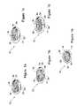
- FIGS. 1 a - 1 fschematically illustrate the application of an integrated tool for clean-margin assessment to a soft tissue that contains a cancerous tissue within and the principles of clean-margin assessment, in accordance with the present invention
- FIGS. 2 a - 2 cschematically illustrate an isometric view, a frontal view, and a cross-sectional view of the integrated tool for clean-margin assessment, in accordance with the present invention
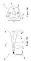
- FIG. 3schematically illustrates an ultrasound distance-measuring sensor of the integrated tool for clean-margin assessment, in accordance with the present invention
- FIGS. 4 a - 4 dfurther illustrate the operational manner of the integrated tool for clean-margin assessment, in accordance with the present invention
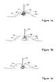
- FIGS. 5 a - 5 cfurther illustrate the operational manner of the integrated tool for clean-margin assessment, in accordance with the present invention
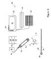
- FIG. 6schematically illustrates an overall system for clean-margin assessment, in accordance with the present invention
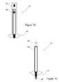
- FIGS. 7 a - 7 dschematically illustrate the integrated tool for clean-margin assessment, which further includes a retractable knife, in accordance with a preferred embodiment of the present invention
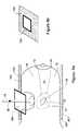
- FIGS. 8 a - 8 bschematically illustrate the integrated tool for clean-margin assessment, operative with a frame for fixing a soft tissue, in accordance with a preferred embodiment of the present invention
- FIGS. 9 a and 9 bschematically illustrate the integrated tool for clean-margin assessment, wherein the tissue-type sensor is formed as a horn antenna, for RF or MW, in accordance with still another embodiment of the present invention
- FIGS. 10 a and 10 bschematically illustrate the integrated tool for clean-margin assessment, wherein the tissue-type sensor is formed as an optical sensor, in accordance with yet another embodiment of the present invention
- FIGS. 11 a and 11 bschematically illustrate the integrated tool for clean-margin assessment, wherein the tissue-type sensor is formed as an MRI sensor, in accordance with yet another embodiment of the present invention
- FIGS. 12 a and 12 bschematically illustrate the integrated tool for clean-margin assessment, wherein the distance-measuring sensor is formed as a strain gauge, in accordance with still another embodiment of the present invention
- FIGS. 13 a and 13 bschematically illustrate the integrated tool for clean-margin assessment, wherein the distance-measuring sensor is formed as a pressure sensor, in accordance with still another embodiment of the present invention.
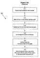
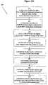
- FIGS. 14 a and 14 billustrate, in flowchart forms, surgical methods of tumor removal, using the integrated tool for clean-margin assessment, in accordance with embodiments of the present invention.
- the present inventionis of an integrated tool, having a tissue-type sensor, for determining the tissue type at a near zone volume of a tissue surface, and a distance-measuring sensor, for determining the distance to an interface with another tissue type.
- the toolis operable for (i) confirming an existence of a clean margin of healthy tissue around a malignant tumor, which is being removed, and (ii) determining the width of the clean margin, wherein both are performed in real time, while the malignant tumor is being removed.
- the tissue-type sensormay be selected from the group of a sensor for tissue electromagnetic properties, a dielectric sensor, an impedance sensor, a sensor for optical fluorescence spectroscopy, a sensor for optical reflectance spectroscopy, an MRI sensor, an RF sensor, an MW sensor, a temperature sensor, and infrared thermography sensor, or another tissue-characterization sensor, as known.
- the distance-measuring sensormay be an ultrasound transducer, an MRI probe, an invasive needle with a strain or pressure gauge, or another tissue distance measuring sensor, as known.
- the integrated toolmay further include a position tracking device and an incision instrument. The soft tissue may be held within a fixed frame, while the tumor is being removed.
- a method for malignant tumor removalcomprising, fixing the soft tissue within a frame, performing imaging with the hand-held, integrated tool, from a plurality of locations and orientations around the soft tissue, reconstructing a three-dimensional image of the soft tissue and the tumor within, defining a desired clean margin on the reconstructed image, calculating a recommended incision path, displaying the recommended path on the reconstructed image, and cutting the tissue while determining its type, at the near zone volume of the incision surface, by the hand-held integrated tool.
- the methodmay further include continuously imaging with the cutting, continuously correcting the reconstructed image and the recommended incision path, and continuously determining the tissue type, at the near zone volume of the incision surface.
- FIGS. 1 a - 1 fschematically illustrate the principles of clean margin assessment and the application of a hand-held, integrated tool 10 for clean-margin assessment, in accordance with the present invention.
- FIGS. 1 a - 1 dillustrate tissue portions 15 which have been removed from the body. These portions include a first tissue type of healthy tissue 14 , enclosing or partly enclosing a second tissue type of cancerous or otherwise abnormal tissue 16 . A tissue surface 18 , which is generally the incision surface, bounds each of the tissue portions 15 .
- tissue surface 18may be a skin, a body lumen, or an incision surface.
- the incision surface 18has a positive margin 27 at a location 19 .
- the near zone at the tissue surface 18is at least one cell layer in thickness, and preferably several cell layers in thickness. In practice, it may range from about 100 microns to about 500 microns.
- the positive margin 27may be defined as a situation where the tissue surface 18 , or the near zone at the tissue surface 18 , contains at least one cancerous cell.
- FIG. 1 afurther illustrates a clean margin at a location 17 , where the tissue surface 18 , or the near zone at the tissue surface 18 , contains no cancerous cells, and thus has a clean margin 24 .
- FIG. 1 billustrates another example of the positive margin 27 , this time at the location 17 .
- the positive margin of FIG. 1 bis due to a shoot 29 , which stems from the second tissue type 16 and which reaches to the surface 18 .
- FIGS. 1 c and 1 dillustrate examples of tissue portions 15 that have been excised with clean margins 24 , at all locations.
- FIG. 1 eillustrates a model for clean margin assessment, showing the second, cancerous tissue type 16 and a layer of a tissue 13 , surrounding it.
- the tissue 13may be a healthy tissue, but may be partly cancerous or otherwise abnormal.
- the aim in characterizing the tissue surface 18is to determine the type of the tissue 13 at various locations along the surface 18 .
- a depth 25 to an interface 22 with the second tissue type 16may be defined. While a sufficient depth may be realized when the depth 25 is only 1 cell layer in thickness, or about 40 microns, it is generally desired that the depth 25 be between about 0.1 and 10 mm.
- the depth 25 of the clean marginmay be desired and may depend on the size and type of the cancerous tumor, forming the second tissue type 16 .
- the tissue portion 15is removed.
- the cutis made through the first tissue type 14 of healthy tissue, so as to completely contain the second tissue type 16 within;
- the depth 25 of the clean margin 24 of the first tissue type 14is sufficient.
- a first sensorfor characterizing the near zone volume of the tissue surface 18 , to ensure that it is of the first tissue type 14 of healthy tissue
- a second sensorfor measuring the depth 25 of the clean margin 24 , to verify that there is sufficient depth between the tissue surface 18 and the interface 22 , which bounds the second tissue type 16 .
- FIG. 1 ffurther illustrates the application of the hand-held, integrated tool 10 for clean-margin assessment, to a tissue 12 .
- the tissue 12includes the healthy tissue, which forms the first tissue type 14 . Additionally, the tissue 12 includes the cancerous or otherwise abnormal tissue, which forms the second tissue type 16 , enclosed within the first tissue type 14 .
- the integrated tool 10determines that a distance 20 between the tissue surface 18 and the interface 22 , which bounds the second tissue type 16 , is about twice as much as the desired depth 25 of the clean margin 24 . In that case, a surgeon may decide to approach the second tissue type 16 further, in order to keep the size of the portion for removal minimal.
- the integrated tool 10may be further used to characterize additional tissue types and determine the distances between their interfaces.
- the various tissue typesmay include bone tissue, fat tissue, muscle tissue, cancerous tissue, or blood clot tissue.
- FIGS. 2 a - 2 cschematically illustrate an isometric view, a proximal view, with respect to the tissue 12 , and a cross-sectional view of the integrated tool 10 for clean-margin assessment, in accordance with a first embodiment of the present invention.
- the integrated tool 10has a proximal end 30 and a distal end 32 , with respect to the surface 18 ( FIG. 1 ).
- a tissue-type sensor 33determines the characteristics of the tissue in the near zone volume of the surface 18 , for example, whether fat, muscle, bone, healthy, cancerous, or otherwise abnormal.
- a distance-measuring sensor 38measures the distance 20 from the surface 18 to the interface 22 with the second tissue type 16 .
- the tissue-type sensor 33measures the electrical properties of the tissue type 13 . By comparing the results with known tissue properties, the characteristic of the tissue type 13 is determined.
- the tissue-type sensor 33may be constructed as a coaxial cable 44 , having an inner electrode 34 and an outer electrode 36 , which together form the sensor 33 .
- the outer electrode 36may be grounded.
- the distance-measuring sensor 38is at least one ultrasound transducer 38 .
- the coaxial cable 44is located within an overall structure 45 .
- the distance-measuring sensor 38such as the at least one ultrasound transducer 38 is also mounted on the structure 45 , for example, along side the tissue-type sensor 33 .
- the distance-measuring sensor 38may be formed of at least two ultrasound transducers 38 , one operating as a transmitter and the other as a receiver. The advantage there is that the instrumentation dead time is shorter.
- the distance-measuring sensor 38may be formed as an array of ultrasound transducers 38 , for providing steering and focusing capabilities, as known.
- Signals from the tissue-type sensor 33 and the distance-measuring sensor 38are transferred for analysis through a cable 46 to a computerized system 95 , described hereinbelow in conjunction with FIG. 6 .
- the inner electrode 34has a diameter 40 of between about 0.2 and 1.5 mm
- the outer electrode 36has an inner diameter 42 of between about 3.0 and 10.0 mm, and is about 0.5 mm thick.
- the outer electrode 36is covered is with an insulating sheath 49 made of an insulating material, for example, Teflon. It will be appreciated that other dimensions, which may be larger or smaller, may similarly be used.
- the sensors 38 and 33may be encased in a filler material 39 , for example epoxy, which may be formed as a plug that fits into the structure 45 , for example, as shown in FIG. 2 c.
- the ultrasound transducer 38operates at a frequency range of between about 0.5 MHz and about 40 MHz. It has an accuracy of about 3 mm, when operating at the lower range of 0.5 MHz, and an accuracy of about 40 micron, when operating at the higher range of 40 MHz.
- the integrated tool 10may further include a position-tracking device 50 , for example, the miniBIRD® 500 or the miniBIRD® 800, which are miniaturized magnetic tracking systems having six degrees of freedom and using sensors, which are merely 5 mm wide, produced by Ascension Technology Corporation, P.O. Box 527 Burlington, Vt. 05402, USA. They are described in http://www.ascension-tech.com/products/minibird.php, downloaded on Mar. 15, 2005.
- the position-tracking device 50may provide the coordinates of the ultrasound measurements, thus enabling a three-dimensional image reconstruction of the ultrasound.
- FIG. 3schematically illustrates the ultrasound distance-measuring sensor 38 of the integrated tool 10 , in operation, in accordance with the present invention.
- the proximal end 30 of the integrated tool 10is brought proximally to the tissue surface 18 , of the tissue 12 , so as to make contact or near contact with it.
- the tissue 12includes the first tissue type 14 of healthy tissue, preferably at the outer portion thereof, and the second tissue type 16 of abnormal tissue, enclosed by the first tissue type 14 of healthy tissue, with tissue 13 , which is suspicious as possibly containing cancerous or otherwise abnormal tissue, surrounding the second tissue type 16 .
- tissue 16is bounded by the interface 22 .
- At least two ultrasound transducers 38are used, 38 A and 38 B, wherein the transducer 38 A is a transmitter for transmitting an ultrasound wave 58 , and the transducer 38 B is the receiver, for receiving an ultrasound echo 60 , from the interface 22 within the tissue 12 . In this manner, instrumentation dead time is reduced.
- the ultrasound sensor 38is preset for a focal distance of about 5 mm, which is the desired depth 25 of the clean margin 24 , thus providing the most accurate results for this distance.
- FIG. 3further illustrates the structure 45 of the coaxial cable 44 and the tissue-type sensor 33 . Additionally, the position-tracking device 50 is shown. When correlated with a tissue coordinate system 54 , illustrated hereinbelow, in conjunction with FIG. 6 , it may be used together with the ultrasound sensor 38 , to provide a three-dimensional image of the tissue 12 and the abnormal tissue type 16 within.
- the cable 46carries the measurements to the computerized system 95 , described hereinbelow in conjunction with FIG. 6 .
- FIGS. 4 a - 4 dfurther illustrate the operational manner of the integrated tool 10 for clean-margin assessment, in accordance with the present invention.
- a radiologistmay place a guide wire under x-ray or ultrasound guidance, so that the proximal tip of the guide wire, with respect to the tissue, is in the tumor.
- an imaging modalityalone, for example, mammography, CT, ultrasound, or another imaging modality may be used to locate the tumor.
- the patientis then transported to the operating room, where the surgeon uses the guide wire, or the image, or palpation to locate the tumor in the breast and to excise a portion of tissue including the cancerous portion and a layer of healthy tissue surrounding the cancerous portion.
- the process of inserting a guide wireis termed, pre-procedure.
- FIGS. 4 a - 4 ctwo methods are possible, without pre-procedure, as illustrated in FIGS. 4 a - 4 c, and with pre-procedure, as illustrated in FIG. 4 d.
- FIGS. 4 a - 4 cschematically illustrate the use of the integrated tool 10 when no guide wire is used.
- the integrated tool 10may be used on the tissue surface 18 , during the removal of the portion 15 , to verify that the cutting proceeds as planned.
- the near zone volume of the surface 18should detected by the tissue type sensor 33 to be of the first tissue type 14 of healthy tissue, and the interface 22 with the second tissue type 16 should be detected at the desired depth 25 . Corrections can be made in real time.
- the integrated tool 10may be used on the tissue surface 18 , after the removal of the portion 15 , to verify that the all the cancerous tissue has been eliminated.
- the near zone volume of the surface 18should detected by the tissue type sensor 33 to be of the first tissue type 14 of healthy tissue, and no interface 22 and no second tissue type 16 should be detected.
- the integrated tool 10will identify it both by the character of the near zone volume of the tissue surface 18 around the portion 72 , and by the presence of the interface 22 , in back of the second tissue type 16 , indicating that two types of tissue remained.
- the integrated tool 10may be used on the tissue surface 18 , of the removed portion 15 , after removal. This, to verify that the all the cancerous tissue is surrounded by the clean margin 24 of the first tissue type 14 of healthy tissue, and of sufficient depth 25 . At this stage, the near zone volume of the surface 18 should be of the first tissue type 14 , and the interface 22 should be detected at the desired depth 25 .
- the integrated tool 10will identify it both by the character of the near zone volume of the tissue surface 18 at the surface 74 , and by the absence of the interface 22 , around the desired depth 25 .
- FIG. 4 dschematically illustrates the use of the integrated tool 10 with a guide wire 78 that has been inserted during pre-procedure, with the help of x-ray or another imaging modality. This procedure often applies to non-palpable tumors, which are difficult to detect.
- the distance-measuring sensor 38is an ultrasound transducer, and the guide wire 78 is visible by the ultrasound. Additionally, a guide-wire transducer 82 may be mounted on the tip 80 , for sending signals that may be received by the distance-measuring sensor 38 . Thus, the distance-measuring sensor 38 may estimate the distance to the tip 80 , hence the distance to the second tissue type 16 .
- the guide wire transducer 82may be, for example, a micro-electromechanical system (MEMS) ultrasound transducer, with a typical size of about 100 ⁇ m in diameter.
- MEMSmicro-electromechanical system
- the distance-measuring sensor 38may include three transducers, for calculating the exact position of the guide wire transducer 82 , by triangulation. It will be appreciated that in the calculation of the distance between the guide wire transducer 82 and the distance-measuring sensor 38 , it is assumed that the sound velocity in cancerous tissue and in healthy tissue is about the same.
- the senor 82 at the tip 80 of the guide wire 78may be a magnetic positioning device, coupled with an RF transmitter, for transmitting its position, via RF signals, which may be received by an RF receiver on the integrated tool 10 .
- FIGS. 4 b and 4 capply, as before.
- FIGS. 5 a - 5 cfurther illustrate the operational manner of the integrated tool 10 for clean-margin assessment, in accordance with the present invention.
- the integrated tool 10is applied to an external surface 11 , such as a skin, forming the surface 18 , prior to cutting and prior to the removal of the portion 15 ( FIG. 1 ).
- the surface 18may be a lumen.
- the tissue-type sensor 33will probably detect that the surface 18 is of the first tissue type 14 of healthy tissue, and the distance-measuring sensor 38 will detect the interface 22 with the second tissue type 16 at some depth.
- the integrated tool 10is applied to the tissue surface 18 , now the tissue surface 18 , to verify that the cutting proceeds as planned.
- the tissue-type sensor 33will detect that the near zone volume of the tissue surface 18 is of the first tissue type 14 of healthy tissue, and the distance-measuring sensor 38 will detect the interface 22 with the second tissue type 16 at some depth, approaching the desired depth 25 of the clean margin 24 . Corrections and adjustments can be made in real time.
- the tissue-type sensor 33will detect that the near zone volume of the tissue surface 18 is of the second tissue type 16 of abnormal tissue, and the distance-measuring sensor 38 will not be able to provide useful information, as no clean margin exists.
- FIG. 6schematically illustrates an overall computerized system 95 , for clean-margin assessment, in accordance with the present invention.
- System 95includes the integrated tool 10 , having the structure 45 , on which the tissue-type sensor 33 and the distance-measuring sensor 38 are mounted. Preferably, both sensors are located at the proximal end 30 , with respect to the tissue. Additionally, the integrated tool 10 may include the position-tracking device 50 , for providing its coordinates with respect to the frame of reference 54 , which defines a six-degree coordinate system, of x, y, z, and the rotational angles around them, ⁇ , ⁇ , and ⁇ .
- Data from the integrated tool 10is carried to appropriate analyzers, preferably associated with a computer 90 for analysis.
- the computer 90may be a personal computer, a laptop, a palmtop, a microcomputer, or another computer, as known.
- an electrical properties sensing module 94includes, for example, an impedance analyzing external unit, such as Agilent 4396A, and a test fixture 89 connected via a coaxial cable to the impedance analyzing external unit.
- the distance-measuring sensor 38such as the ultrasound transducer 38 is associated with an ultrasound signal generator and analyzer 96 .
- the position-tracking device 50may be associated with an analyzer 98 .
- the sensorsmay be battery operated or associated with power supply units.
- the computer 90which receives the data from the analyzers, preferably includes a user interface, for example, a keyboard 97 , or knobs, and may further include storage systems, such as a read and write drive 91 , a USB port 93 , and a display screen 92 .
- a user interfacefor example, a keyboard 97 , or knobs
- storage systemssuch as a read and write drive 91 , a USB port 93 , and a display screen 92 .
- the unit 94 typewill complement that sensor 33 .
- the unit 94will be an optical analyzer.
- the unit 96will complement that sensor 38 .
- Information from the distance-measuring sensor 38 together with that of the position-tracking device 50may be used for reconstructing a three-dimensional image of the tissue, by the computer 90 . Additionally, the three-dimensional image may be is displayed on the screen 92 .
- the system 95may further include a guide wire 78 .
- the guide wiremay include a sensor 82 , which may be an ultrasound transducer or a magnetic positioning device, coupled with a transmitter, for transmitting the positioning of the proximal tip, when inserted in the tissue, as taught hereinabove, in conjunction with FIG. 4 d.
- the sensor 82is wireless, and operates via external interrogation, for example, from the distance-measuring sensor 38 , or on battery.
- FIGS. 7 a - 7 dschematically illustrate the integrated tool 10 , which further includes a retractable knife 106 , in accordance with a preferred embodiment of the present invention.
- the knifeis retracted, and the tool is used as described hereinabove.
- the knifeis deployed, and the tool is used for removing the portion 15 .
- surgeonmay use the integrated tool 10 both for measuring and characterizing the clean margin and for removing the portion 15 .
- FIG. 7 cillustrates the proximal view of the integrated tool 10 , in accordance with the present embodiment, while FIG. 7 d provides a cross-sectional view.
- Retraction and deploymentare controlled by a knob 108 .
- the knife 106may be a cold knife, a diathermal knife, or another knife, as known.
- FIGS. 8 a - 8 bschematically illustrate the integrated tool 10 , operative with a frame 100 for fixing the soft tissue 12 , in accordance with a preferred embodiment of the present invention.
- the frame 100has a support plate 101 and a compression plate 102 .
- the compression plate 102defines an opening 104 , through which the integrated tool 10 may be inserted.
- tissue-type sensor 33various sensors may be used for the tissue-type sensor 33 , for characterizing the near zone volume of the tissue surface 18 in contact with the integrated tool 10 . These are illustrated below, in conjunction with FIGS. 9 a - 12 b.
- FIGS. 9 a and 9 bschematically illustrate the integrated tool 10 , wherein the tissue-type sensor 33 is formed as an RF or MW horn antenna 37 , mounted on the structure 45 , in accordance with still another embodiment of the present invention.
- the RF or MW horn antenna 37is associated with an RF/MW transmission line or wave guide 31 , while unit 94 ( FIG. 6 ) is an RF/MW generation, collection and analysis unit.
- the present embodimentrelies on RF microwave characterization by the generation of propagating radiation in the RF microwave region of the electromagnetic spectrum, towards the tissue, and measuring its reflection.
- the radiationis usually transmitted and received by an antenna, for example the horn antenna 37 .
- the tissue characterizationis done by analyzing the amplitude and phase difference between the original waves to the reflected wave.
- FIGS. 10 a and 10 bschematically illustrate the integrated tool 10 , wherein the tissue-type sensor 33 is formed as an optical sensor 47 , mounted on the structure 45 , in accordance with yet another embodiment of the present invention.
- An optical signalis generated in an external unit, such as unit 94 ( FIG. 6 ) and transmitted via an optical fiber 41 to the tissue.
- the reflection of the lightis then received in a dedicated module inside the optical unit.
- the optical energyis usually transmitted to and from the tissue via a lens 43 .
- optical signal generationreceives and analyzing the details of optical signal generation, receiving and analyzing depend on the specific optical method that is chosen.
- tissue characterizationrelies on measuring the relative amplitude and phase of the reflected light versus the generated light.
- An example for the reflection spectroscopy methodis described in commonly owned U.S. patent application Ser. No. 10/298196, whose disclosure is incorporated herein by reference. It will be appreciated that other methods may be used, as known.
- auto florescencemay be used, for measuring emitted radiation, from the tissue, at different a wavelength than that originally transmitted.
- the emitted radiationoccurs in response to excitation by impinging radiation, and may be used for tissue characterization, for example, as used by Xillix Technologies Corp., #100-13775 Commerce Parkway, Richmond, British Columbia, Canada V6V 2V4, Telephone: 604-278-5000, and described in http://www.xillix.com/index home.cfm. It will be appreciated that other methods may be used, as known.
- FIGS. 11 a and 11 bschematically illustrate the integrated tool for clean-margin assessment, wherein the tissue-type sensor 33 is formed as an MRI sensor 51 , in accordance with yet another embodiment of the present invention.
- the MRI sensor 51has a permanent magnet 55 , enclosed in an RF coil 53 , for example, as taught in commonly owned U.S. Patent Application 2005/0021019 to Hashimshony et al., entitled “Method and apparatus for examining substance, particularly tissue, to characterize its type,” whose disclosure is incorporated herein by reference, and in U.S. Pat. No. 5,572,132, to Pulyer, et al., entitled, “MRI probe for external imaging,” whose disclosure is incorporated herein by reference.
- various sensorsmay be used for the distance-measuring sensor 38 , as illustrated below, in conjunction with FIG. 13 .
- tissue characterization sensorsmay be used, as known. These may include a sensor for tissue electromagnetic properties, a dielectric sensor, an impedance sensor, a sensor for optical fluorescence spectroscopy, a sensor for optical reflectance spectroscopy, an MRI sensor, a temperature sensor, and infrared thermography sensor, or another tissue-characterization sensor, as known.
- FIGS. 12 a and 12 bschematically illustrate the integrated tool 10 , wherein the distance-measuring sensor 38 is formed as a strain gauge 66 , in accordance with still another embodiment of the present invention.
- the present embodimentutilizes the approach of U.S. Pat. No. 6,546,787 to Schiller et al., whose disclosure is incorporated herein by reference, and which provides an apparatus and method for detecting a distance from a tissue edge to a malignant tissue, enclosed therein, i.e., a margin.
- the apparatuscomprises a needle having a strain gage, mounted on one of the needles walls. Strain signals are collected as the needle is moved through the tissue. The needle is inserted at different points to allow data collection from different points within the tissue. The data is sent together with its spatial coordinates to a computerized system, which provides an image of the structure of the examined tissue.
- the structure 45 of the integrated tool 10may include a lumen 65 , wherein a needle 60 may be retracted and deployed, via a knob 62 .
- the needlehas a sharp edge 64 , for penetrating the tissue.
- the strain gauge 66senses the tissue resistance to the penetration, and provides data of resistance as a function of needle penetration depth. These measurements may be performed at various locations along the tissue surface 18 .
- FIGS. 13 a and 13 bschematically illustrate the integrated tool 10 , wherein the distance-measuring sensor 38 is formed as a pressure sensor 68 , at the needle's tip, in accordance with yet another embodiment of the present invention.
- the structure 45 of the integrated tool 10may include the lumen 65 , wherein the needle 60 may be retracted and deployed, via the knob 62 .
- the pressure sensor 68senses the tissue resistance to the penetration, and provides data of resistance as a function of needle penetration depth. These measurements may be performed at various locations along the tissue surface 18 .
- a non-invasive imagermay be used for the distance-measuring sensor 38 , for example, an MRI sensor.
- the integrated tool 10may be formed, for example, with the tissue-type sensor 33 being an optical sensor, and the distance-measuring sensor 38 being a on-invasive imager, such as an MRI sensor.
- FIGS. 14 a and 14 billustrate, in flowchart forms, surgical methods of tumor removal, using the integrated tool 10 , in accordance with embodiments of the present invention
- a method 200provides a computer-guided surgery, as follows:
- a method 230further provides continuous correction to the method 200 , as follows:
- the knifeis integrated with the tool, as taught in conjunction with FIGS. 7 a - 7 d.
Landscapes
- Health & Medical Sciences (AREA)
- Life Sciences & Earth Sciences (AREA)
- Surgery (AREA)
- Engineering & Computer Science (AREA)
- Public Health (AREA)
- Veterinary Medicine (AREA)
- General Health & Medical Sciences (AREA)
- Animal Behavior & Ethology (AREA)
- Biomedical Technology (AREA)
- Heart & Thoracic Surgery (AREA)
- Medical Informatics (AREA)
- Molecular Biology (AREA)
- Physics & Mathematics (AREA)
- Pathology (AREA)
- Biophysics (AREA)
- Nuclear Medicine, Radiotherapy & Molecular Imaging (AREA)
- Radiology & Medical Imaging (AREA)
- Endocrinology (AREA)
- Gynecology & Obstetrics (AREA)
- Reproductive Health (AREA)
- Plasma & Fusion (AREA)
- Immunology (AREA)
- Vascular Medicine (AREA)
- Otolaryngology (AREA)
- Robotics (AREA)
- Surgical Instruments (AREA)
- Magnetic Resonance Imaging Apparatus (AREA)
- Investigating Or Analysing Biological Materials (AREA)
Abstract
Description
- 1. There are technical challenges associated with placement of the guide wire tip, and the radiologist may not place the guide wire properly through the lesion. It is particularly difficult to place the guide wire at the correct depth. Also, when the guide wire is placed under x-ray guidance, the breast is compressed. When the breast is decompressed for the surgical excision, the guide wire can move, resulting in inaccurate placement thereof. Finally, the guide wire placement procedure is uncomfortable to the patient and logistically challenging; the procedure must be coordinated with the time of surgery. Often, the easiest path for the radiologist to place the guide wire is different from the best surgical approach, so the surgeon cannot follow the guide wire down to the tumor.
- 2. It is difficult to estimate correctly the full extent of the disease and the exact volume of the cancerous portion of the tumor, especially with non-palpable lesions. Non-palpable lesions are similar in their properties to normal tissue, hence harder to detect by ultrasound and mammography. Thus, the guide wire may be inaccurately placed. To compensate for the imprecision in determining the extent of the disease, the surgeon must remove much more tissue than would be required if the full extent of the cancer could be imaged in real-time. This leads to a negative impact aesthetically and emotionally on the patient.
R=(Z2−Z1)2/(Z2+Z1)2,
Z=ρv.
- the distance between the tissue surface and an interface with the cancerous tissue.
- a structure, which defines a proximal end with respect to a tissue and which is adapted for placement proximally to the tissue;
- a tissue-type sensor, mounted on the structure, for determining a tissue type at a near zone volume of a tissue surface; and
- a distance-measuring sensor, mounted on the structure, for determining a distance between the tissue surface and an interface with another tissue type;
- a tissue-type-sensor analyzer, associated with the tissue-type sensor;
- a distance-measuring-sensor analyzer, associated with the distance-measuring sensor;
- an output device, which provides output of measurements by the tissue-type sensor and the distance-measuring sensor.
- a structure, which defines a proximal end with respect to the tissue and which is adapted for placement proximally to the tissue;
- a tissue-type sensor, mounted on the structure, for determining a tissue type at a near zone volume of a tissue surface;
- an imager, operative as a distance-measuring sensor, mounted on the structure, for determining a distance between the tissue surface and an interface with another tissue type; and
- a position-tracking device, mounted on the structure and correlated with the coordinate system;
- a tissue-type-sensor-analyzer, associated with the tissue-type sensor;
- a distance-measuring-sensor analyzer, associated with the distance-measuring sensor;
- a position-tracking-device analyzer, associated with the position-tracking device;
- a computer, for receiving data from the tissue-type-sensor analyzer, the distance-measuring-sensor analyzer, and the position-tracking-device analyzer, and performing analysis thereof;
- an output device, associated with the computer.
- a structure, which defines a proximal end with respect to a tissue and which is adapted for placement proximally to the tissue;
- a tissue-type sensor, mounted on the structure, for determining a tissue type at a near zone volume of a tissue surface; and
- a distance-measuring sensor, mounted on the structure, for determining a distance between the tissue surface and an interface with another tissue type;
- a structure, which defines a proximal end with respect to a tissue and which is adapted for placement proximally to the tissue;
- a tissue-type sensor, mounted on the structure, for determining a tissue type at a near zone volume of a tissue surface; and
- a non-invasive imager, mounted on the structure; and
- a position-tracking device, mounted on the structure;
- in a box202: providing the hand-held, integrated
tool 10, which includes:- i. the tissue-
type sensor 33, for determining a tissue type at a near zone volume of a tissue surface; - ii. the
non-invasive imager 38, for example, an ultrasound sensor, or an MRI sensor; and - iii. the
position tracking device 50.
- i. the tissue-
- in a box204: fixing the tissue within a fixed frame, which defines a coordinate system, preferably of six-degrees, x, y, z, and the rotational angles around them, ω, θ, and ρ.
- in a box206: imaging the tissue, within the fixed frame, from at least two, and preferably, a plurality of locations and orientations, by the hand-held, integrated
tool 10. - in a box208: reconstructing, by a computer, a three dimensional image of the tissue.
- in a box210: displaying the three dimensional image of the tissue.
- in a box212: defining a desired clean margin around a second tissue type.
- in a box214: displaying the desired clean margin.
- in a box216: calculating a recommended incision path.
- in a box218: displaying the recommended incision path.
- in a box220: providing an incision instrument.
- in a box222: cutting along the recommended incision path.
- in a box224: determining the tissue type at the near zone volume of the tissue surface, by the hand-held, integrated
tool 10.
- in a box232: continuously imaging the tissue, from different locations and orientations along the tissue surface, by the hand-held, integrated
tool 10. - in a box234: continuously correcting the three dimensional image reconstruction of the tissue, as the tissue is being cut.
- in a box236: continuously correcting the display of the three dimensional image of the tissue.
- in a box238: continuously correcting the desired clean margin around the second tissue type.
- in a box240: continuously displaying the continuously corrected desired clean margin.
- in a box242: continuously correcting the recommended incision path.
- in a box244: continuously displaying the continuously corrected recommended incision path.
- in a
box 246 continuously determining the tissue type, at the near zone volume of the incision surface, by the hand-held, integratedtool 10.
Claims (34)
Priority Applications (7)
| Application Number | Priority Date | Filing Date | Title |
|---|---|---|---|
| US10/558,831US7720532B2 (en) | 2004-03-23 | 2005-03-23 | Clean margin assessment tool |
| US11/705,143US8019411B2 (en) | 2002-01-04 | 2007-02-12 | Probes, systems, and methods for examining tissue according to the dielectric properties thereof |
| US11/797,167US8032211B2 (en) | 2002-01-04 | 2007-05-01 | Probes, systems, and methods for examining tissue according to the dielectric properties thereof |
| US11/797,166US20080287750A1 (en) | 2002-01-04 | 2007-05-01 | Ergonomic probes |
| US11/745,334US7904145B2 (en) | 2004-03-23 | 2007-05-07 | Clean margin assessment tool |
| US12/483,738US9750425B2 (en) | 2004-03-23 | 2009-06-12 | Graphical user interfaces (GUI), methods and apparatus for data presentation |
| US15/665,829US11179053B2 (en) | 2004-03-23 | 2017-08-01 | Graphical user interfaces (GUI), methods and apparatus for data presentation |
Applications Claiming Priority (3)
| Application Number | Priority Date | Filing Date | Title |
|---|---|---|---|
| US55590104P | 2004-03-23 | 2004-03-23 | |
| US10/558,831US7720532B2 (en) | 2004-03-23 | 2005-03-23 | Clean margin assessment tool |
| PCT/IL2005/000330WO2005089065A2 (en) | 2004-03-23 | 2005-03-23 | Clean margin assessment tool |
Related Parent Applications (3)
| Application Number | Title | Priority Date | Filing Date |
|---|---|---|---|
| PCT/IL2005/000330A-371-Of-InternationalWO2005089065A2 (en) | 2002-01-04 | 2005-03-23 | Clean margin assessment tool |
| PCT/IL2006/000908Continuation-In-PartWO2007015255A2 (en) | 2002-01-04 | 2006-08-06 | Tissue-characterization probe with effective sensor-to-tissue contact |
| US11/743,028Continuation-In-PartUS20070255169A1 (en) | 2001-11-19 | 2007-05-01 | Clean margin assessment tool |
Related Child Applications (5)
| Application Number | Title | Priority Date | Filing Date |
|---|---|---|---|
| PCT/IL2006/000015Continuation-In-PartWO2006072947A2 (en) | 2002-01-04 | 2006-01-04 | Endoscopic system for in-vivo procedures |
| US11/567,581Continuation-In-PartUS7471103B2 (en) | 2006-12-06 | 2006-12-06 | Method for implementing complex logic within a memory array |
| US11/705,143Continuation-In-PartUS8019411B2 (en) | 2002-01-04 | 2007-02-12 | Probes, systems, and methods for examining tissue according to the dielectric properties thereof |
| US11/743,028Continuation-In-PartUS20070255169A1 (en) | 2001-11-19 | 2007-05-01 | Clean margin assessment tool |
| US11/797,167Continuation-In-PartUS8032211B2 (en) | 2002-01-04 | 2007-05-01 | Probes, systems, and methods for examining tissue according to the dielectric properties thereof |
Publications (2)
| Publication Number | Publication Date |
|---|---|
| US20060253107A1 US20060253107A1 (en) | 2006-11-09 |
| US7720532B2true US7720532B2 (en) | 2010-05-18 |
Family
ID=34994122
Family Applications (1)
| Application Number | Title | Priority Date | Filing Date |
|---|---|---|---|
| US10/558,831Active2027-03-21US7720532B2 (en) | 2002-01-04 | 2005-03-23 | Clean margin assessment tool |
Country Status (3)
| Country | Link |
|---|---|
| US (1) | US7720532B2 (en) |
| EP (1) | EP1740102A4 (en) |
| WO (1) | WO2005089065A2 (en) |
Cited By (21)
| Publication number | Priority date | Publication date | Assignee | Title |
|---|---|---|---|---|
| US20070032739A1 (en)* | 2005-08-04 | 2007-02-08 | Dune Medical Devices Ltd. | Device for forming an effective sensor-to-tissue contact |
| US20070197895A1 (en)* | 2006-02-17 | 2007-08-23 | Sdgi Holdings, Inc. | Surgical instrument to assess tissue characteristics |
| US20080154090A1 (en)* | 2005-01-04 | 2008-06-26 | Dune Medical Devices Ltd. | Endoscopic System for In-Vivo Procedures |
| US20080287750A1 (en)* | 2002-01-04 | 2008-11-20 | Dune Medical Devices Ltd. | Ergonomic probes |
| US20090054908A1 (en)* | 2005-04-15 | 2009-02-26 | Jason Matthew Zand | Surgical instruments with sensors for detecting tissue properties, and system using such instruments |
| US20090187109A1 (en)* | 2001-11-19 | 2009-07-23 | Dune Medical Devices Ltd. | Method and apparatus for examining tissue for predefined target cells, particularly cancerous cells, and a probe useful in such method and apparatus |
| US20090220415A1 (en)* | 2005-12-16 | 2009-09-03 | Shachaf Catherine M | Diagnostic system for the detection of skin cancer |
| US20110046659A1 (en)* | 2007-07-09 | 2011-02-24 | Immersion Corporation | Minimally Invasive Surgical Tools With Haptic Feedback |
| US8523043B2 (en) | 2010-12-07 | 2013-09-03 | Immersion Corporation | Surgical stapler having haptic feedback |
| US20140187930A1 (en)* | 2012-12-28 | 2014-07-03 | Sony Corporation | Microwave transmission device and microwave transmission system |
| US8780362B2 (en) | 2011-05-19 | 2014-07-15 | Covidien Lp | Methods utilizing triangulation in metrology systems for in-situ surgical applications |
| US8801710B2 (en) | 2010-12-07 | 2014-08-12 | Immersion Corporation | Electrosurgical sealing tool having haptic feedback |
| US8845667B2 (en) | 2011-07-18 | 2014-09-30 | Immersion Corporation | Surgical tool having a programmable rotary module for providing haptic feedback |
| US9113822B2 (en) | 2011-10-27 | 2015-08-25 | Covidien Lp | Collimated beam metrology systems for in-situ surgical applications |
| US20150313473A1 (en)* | 2012-12-18 | 2015-11-05 | Koninklijke Philips N.V. | Reusable mr safe temperature probe for surface and body temperature measurement |
| US9351643B2 (en) | 2013-03-12 | 2016-05-31 | Covidien Lp | Systems and methods for optical measurement for in-situ surgical applications |
| US9526460B2 (en) | 2005-08-04 | 2016-12-27 | Dune Medical Devices Ltd. | Tissue-characterization probe with effective sensor-to-tissue contact |
| US9579143B2 (en) | 2010-08-12 | 2017-02-28 | Immersion Corporation | Electrosurgical tool having tactile feedback |
| EP3685781A1 (en) | 2019-01-24 | 2020-07-29 | Erbe Elektromedizin GmbH | Device for tissue coagulation |
| WO2024238339A3 (en)* | 2023-05-15 | 2025-03-20 | University Of Pittsburgh - Of The Commonwealth System Of Higher Education | Devices, systems, and methods for controlling powered surgical instruments |
| US12419550B2 (en) | 2014-04-05 | 2025-09-23 | Surgisense Corporation | Apparatus, systems, and methods for mapping of tissue oxygenation |
Families Citing this family (52)
| Publication number | Priority date | Publication date | Assignee | Title |
|---|---|---|---|---|
| US20070255169A1 (en)* | 2001-11-19 | 2007-11-01 | Dune Medical Devices Ltd. | Clean margin assessment tool |
| US8032211B2 (en) | 2002-01-04 | 2011-10-04 | Dune Medical Devices Ltd. | Probes, systems, and methods for examining tissue according to the dielectric properties thereof |
| US8019411B2 (en) | 2002-01-04 | 2011-09-13 | Dune Medical Devices Ltd. | Probes, systems, and methods for examining tissue according to the dielectric properties thereof |
| US7809425B2 (en) | 2003-07-24 | 2010-10-05 | Dune Medical Devices Ltd. | Method and apparatus for examining a substance, particularly tissue, to characterize its type |
| US7720532B2 (en) | 2004-03-23 | 2010-05-18 | Dune Medical Ltd. | Clean margin assessment tool |
| US7904145B2 (en) | 2004-03-23 | 2011-03-08 | Dune Medical Devices Ltd. | Clean margin assessment tool |
| US9750425B2 (en) | 2004-03-23 | 2017-09-05 | Dune Medical Devices Ltd. | Graphical user interfaces (GUI), methods and apparatus for data presentation |
| ES2434851T3 (en) | 2005-03-29 | 2013-12-17 | Dune Medical Devices Ltd. | Electromagnetic sensors for tissue characterization |
| US20100261985A1 (en)* | 2006-03-31 | 2010-10-14 | Koninklijke Philips Electronics, N.V. | Method and apparatus for determining hydration levels from skin turgor |
| AU2007327573B2 (en)* | 2006-11-30 | 2013-07-18 | Impedimed Limited | Measurement apparatus |
| CN101606158B (en) | 2006-12-12 | 2014-04-02 | 沙丘医疗设备有限公司 | Graphical user interfaces (gui), methods and apparatus for data presentation |
| US8147423B2 (en) | 2007-03-01 | 2012-04-03 | Dune Medical Devices, Ltd. | Tissue-characterization system and method |
| DE102007019333A1 (en)* | 2007-04-24 | 2008-11-06 | Siemens Ag | Medical instrument for performing a medical procedure |
| US9999353B2 (en)* | 2007-07-16 | 2018-06-19 | Dune Medical Devices Ltd. | Medical device and method for use in tissue characterization and treatment |
| EP2626030A3 (en)* | 2007-08-14 | 2017-03-08 | Koninklijke Philips N.V. | Robotic instrument systems and methods utilizing optical fiber sensors |
| FR2920086A1 (en) | 2007-08-24 | 2009-02-27 | Univ Grenoble 1 | ANALYSIS SYSTEM AND METHOD FOR ENDOSCOPY SURGICAL OPERATION |
| US8983581B2 (en) | 2008-05-27 | 2015-03-17 | Massachusetts Institute Of Technology | System and method for large field of view, single cell analysis |
| ES2627041T3 (en) | 2008-06-11 | 2017-07-26 | Dune Medical Devices Ltd. | Double registration |
| US8125331B2 (en) | 2008-08-27 | 2012-02-28 | The Invention Science Fund I, Llc | Health-related signaling via wearable items |
| US8284046B2 (en) | 2008-08-27 | 2012-10-09 | The Invention Science Fund I, Llc | Health-related signaling via wearable items |
| US8130095B2 (en) | 2008-08-27 | 2012-03-06 | The Invention Science Fund I, Llc | Health-related signaling via wearable items |
| US8094009B2 (en) | 2008-08-27 | 2012-01-10 | The Invention Science Fund I, Llc | Health-related signaling via wearable items |
| US9155471B2 (en) | 2009-05-27 | 2015-10-13 | Lumicell, Inc'. | Methods and systems for spatially identifying abnormal cells |
| JP2013509902A (en)* | 2009-11-04 | 2013-03-21 | コーニンクレッカ フィリップス エレクトロニクス エヌ ヴィ | Collision avoidance and detection using distance sensors |
| US9314304B2 (en) | 2010-12-08 | 2016-04-19 | Lumicell, Inc. | Methods and system for image guided cell ablation with microscopic resolution |
| WO2012164567A1 (en)* | 2011-06-02 | 2012-12-06 | Dune Medical Devices Ltd. | Tissue sampling for pathological study |
| ES2568225T3 (en) | 2011-09-06 | 2016-04-28 | Ezono Ag | Imaging probe and method to obtain position and / or orientation information |
| CN104303067B (en)* | 2012-03-21 | 2017-05-03 | 明确医疗有限公司 | Mri system for margin assessment of ex-vivo sample |
| US9257220B2 (en) | 2013-03-05 | 2016-02-09 | Ezono Ag | Magnetization device and method |
| US9459087B2 (en) | 2013-03-05 | 2016-10-04 | Ezono Ag | Magnetic position detection system |
| GB201303917D0 (en) | 2013-03-05 | 2013-04-17 | Ezono Ag | System for image guided procedure |
| AU2014236561B2 (en) | 2013-03-14 | 2018-08-16 | Lumicell, Inc. | Medical imaging device and methods of use |
| US10716536B2 (en) | 2013-07-17 | 2020-07-21 | Tissue Differentiation Intelligence, Llc | Identifying anatomical structures |
| EP3041427B1 (en)* | 2013-09-06 | 2024-11-06 | Brigham and Women's Hospital, Inc. | System for a tissue resection margin measurement device |
| US10595816B2 (en) | 2013-12-20 | 2020-03-24 | Kononklijke Philips N.V. | System and method for tracking a penetrating instrument |
| CN105747294B (en)* | 2015-04-13 | 2017-06-06 | 北京至感传感器技术研究院有限公司 | Chest pad, chest pad component and mammary tumor detection means |
| WO2017161097A1 (en)* | 2016-03-16 | 2017-09-21 | Ohio State Innovation Foundation | System and method for the discrimination of tissues using a fast infrared cancer probe |
| US11986341B1 (en)* | 2016-05-26 | 2024-05-21 | Tissue Differentiation Intelligence, Llc | Methods for accessing spinal column using B-mode imaging to determine a trajectory without penetrating the the patient's anatomy |
| US11701086B1 (en) | 2016-06-21 | 2023-07-18 | Tissue Differentiation Intelligence, Llc | Methods and systems for improved nerve detection |
| US11633176B2 (en) | 2016-08-03 | 2023-04-25 | Boston Scientific Scimed Inc. | Positioning devices, methods, and systems |
| CN110461218A (en) | 2017-01-30 | 2019-11-15 | 诺伊斯佩拉医疗有限公司 | Midfield Transmitter and Injectable Midfield Receiver |
| KR20180091282A (en)* | 2017-02-06 | 2018-08-16 | 삼성메디슨 주식회사 | Ultrasonic probe and controlling method of thereof |
| US11759184B2 (en) | 2017-08-07 | 2023-09-19 | Utah Valley University | Apparatus, system and method for diagnostic imaging forceps |
| US11071595B2 (en) | 2017-12-14 | 2021-07-27 | Verb Surgical Inc. | Multi-panel graphical user interface for a robotic surgical system |
| KR102477325B1 (en)* | 2017-12-14 | 2022-12-16 | 버브 서지컬 인크. | Multi-panel graphical user interface for robotic surgical systems |
| US10561842B2 (en) | 2017-12-14 | 2020-02-18 | NeuSpera Medical Inc. | Layered midfield transmitter with dielectric tuning |
| US11596794B2 (en) | 2017-12-14 | 2023-03-07 | NeuSpera Medical Inc. | Enhanced wireless communication and power transfer between external and implanted devices |
| US10959747B1 (en) | 2018-04-02 | 2021-03-30 | Lifei Guo | Tissue removing |
| CA3096463A1 (en)* | 2018-04-12 | 2019-10-17 | NeuSpera Medical Inc. | Midfield power source for wireless implanted devices |
| RU184916U1 (en)* | 2018-07-02 | 2018-11-14 | Государственное бюджетное учреждение здравоохранения города Москвы Научно-исследовательский институт скорой помощи имени Н.В. Склифосовского Департамента здравоохранения г. Москвы | DEVICE FOR ATRUMATIC REMOVAL OF A PATHOLOGICAL BLOOD ON THE MURTH OF THE LARYNX, TRACHEAS AND BRONCHES |
| CN111297336B (en)* | 2020-02-24 | 2021-08-06 | 清华大学 | A body temperature measurement method, device and security inspection equipment based on infrared and terahertz |
| TR202003070A2 (en)* | 2020-02-28 | 2021-09-21 | Istanbul Teknik Ueniversitesi Bilimsel Ararstirma Proje Birim | TISSUE ANALYSIS DEVICE AND TISSUE ANALYSIS METHOD FOR THE CHARACTERIZATION OF PROSTATE CANCER WITH MICROWAVE |
Citations (95)
| Publication number | Priority date | Publication date | Assignee | Title |
|---|---|---|---|---|
| US3830224A (en) | 1972-12-19 | 1974-08-20 | Vanzetti Infrared Computer Sys | Means for detecting changes in the temperature of the skin |
| US4291708A (en) | 1977-11-02 | 1981-09-29 | Yeda Research & Development Co. Ltd. | Apparatus and method for detection of tumors in tissue |
| US4344440A (en) | 1980-04-01 | 1982-08-17 | Trygve Aaby | Microprobe for monitoring biophysical phenomena associated with cardiac and neural activity |
| US4458694A (en) | 1977-11-02 | 1984-07-10 | Yeda Research & Development Co., Ltd. | Apparatus and method for detection of tumors in tissue |
| US4537203A (en) | 1980-10-21 | 1985-08-27 | Tokyo Shibaura Denki Kabushiki Kaisha | Abnormal cell detecting device |
| US4539640A (en) | 1982-01-12 | 1985-09-03 | Tasc Ltd. | Reconstruction system and methods for impedance imaging |
| USRE32000E (en) | 1978-05-22 | 1985-10-08 | B.C.S.I. Laboratories, Inc. | Device for use in early detection of breast cancer |
| US4617939A (en) | 1982-04-30 | 1986-10-21 | The University Of Sheffield | Tomography |
| US4625171A (en) | 1983-02-14 | 1986-11-25 | Hitachi, Ltd. | Imaging apparatus using nuclear magnetic resonance |
| US4682594A (en) | 1985-03-11 | 1987-07-28 | Mcm Laboratories, Inc. | Probe-and-fire lasers |
| US4689567A (en) | 1984-06-01 | 1987-08-25 | Advanced Nmr Systems, Inc. | NMR Fourier imaging from multiple echoes |
| DE3637549A1 (en) | 1986-11-04 | 1988-05-11 | Hans Dr Med Rosenberger | Measuring device for testing the dielectric properties of biological tissues |
| US4751464A (en) | 1987-05-04 | 1988-06-14 | Advanced Nmr Systems, Inc. | Cavity resonator with improved magnetic field uniformity for high frequency operation and reduced dielectric heating in NMR imaging devices |
| US4768513A (en) | 1986-04-21 | 1988-09-06 | Agency Of Industrial Science And Technology | Method and device for measuring and processing light |
| US4785806A (en) | 1987-01-08 | 1988-11-22 | Yale University | Laser ablation process and apparatus |
| EP0419235A1 (en)* | 1989-09-19 | 1991-03-27 | Rocket of London Limited | Loop electrode |
| US5115137A (en) | 1989-02-22 | 1992-05-19 | Spectraphos Ab | Diagnosis by means of fluorescent light emission from tissue |
| US5143079A (en) | 1989-08-02 | 1992-09-01 | Yeda Research And Development Company Limited | Apparatus for detection of tumors in tissue |
| US5227730A (en) | 1992-09-14 | 1993-07-13 | Kdc Technology Corp. | Microwave needle dielectric sensors |
| US5383454A (en)* | 1990-10-19 | 1995-01-24 | St. Louis University | System for indicating the position of a surgical probe within a head on an image of the head |
| US5442290A (en) | 1992-08-04 | 1995-08-15 | The Regents Of The University Of California | MRI gradient drive current control using all digital controller |
| US5482041A (en) | 1992-06-05 | 1996-01-09 | Wilk; Peter J. | Medical investigation system and related method |
| US5558092A (en) | 1995-06-06 | 1996-09-24 | Imarx Pharmaceutical Corp. | Methods and apparatus for performing diagnostic and therapeutic ultrasound simultaneously |
| US5572132A (en) | 1995-08-15 | 1996-11-05 | Pulyer; Yuly M. | MRI probe for external imaging |
| WO1997012553A1 (en) | 1995-10-03 | 1997-04-10 | Changus James E | Lumpectomy facilitating apparatus and methods related thereto |
| US5630426A (en) | 1995-03-03 | 1997-05-20 | Neovision Corporation | Apparatus and method for characterization and treatment of tumors |
| US5678565A (en)* | 1992-12-21 | 1997-10-21 | Artann Corporation | Ultrasonic elasticity imaging method and device |
| US5699804A (en)* | 1995-06-07 | 1997-12-23 | Siemens Aktiengesellschaft | Therapy apparatus having a source of acoustic waves |
| US5704355A (en) | 1994-07-01 | 1998-01-06 | Bridges; Jack E. | Non-invasive system for breast cancer detection |
| AU688352B2 (en) | 1993-07-14 | 1998-03-12 | Masimo Corporation | Sensor probe comprising a finger cot and a source and detector of eletromagnetic energy |
| US5727569A (en) | 1996-02-20 | 1998-03-17 | Cardiothoracic Systems, Inc. | Surgical devices for imposing a negative pressure to fix the position of cardiac tissue during surgery |
| US5735278A (en) | 1996-03-15 | 1998-04-07 | National Research Council Of Canada | Surgical procedure with magnetic resonance imaging |
| US5744971A (en) | 1994-09-09 | 1998-04-28 | Chan; Tsing Yee Amy | Device and apparatus for measuring dielectric properties of materials |
| US5758646A (en) | 1994-09-12 | 1998-06-02 | U.S. Philips Corporation | Magnetic resonance imaging method with pulse sequence optimization and device for such method |
| US5800350A (en) | 1993-11-01 | 1998-09-01 | Polartechnics, Limited | Apparatus for tissue type recognition |
| US5810742A (en) | 1994-10-24 | 1998-09-22 | Transcan Research & Development Co., Ltd. | Tissue characterization based on impedance images and on impedance measurements |
| US5821410A (en) | 1996-09-20 | 1998-10-13 | Regents Of The University Of California | Scanning tip microwave near field microscope |
| US5829437A (en) | 1994-07-01 | 1998-11-03 | Interstitial, Inc. | Microwave method and system to detect and locate cancers in heterogenous tissues |
| US5884239A (en) | 1995-12-27 | 1999-03-16 | Romanik, Jr.; Carl J. | Optical system for accurate monitoring of the position and orientation of an object |
| US5900618A (en) | 1997-08-26 | 1999-05-04 | University Of Maryland | Near-field scanning microwave microscope having a transmission line with an open end |
| US5927284A (en) | 1995-09-20 | 1999-07-27 | Medtronic, Inc | Method and apparatus for temporarily immobilizing a local area of tissue |
| US6010455A (en) | 1995-11-27 | 2000-01-04 | Hill-Rom, Inc. | Skin perfusion evaluation apparatus |
| US6026323A (en) | 1997-03-20 | 2000-02-15 | Polartechnics Limited | Tissue diagnostic system |
| US6061589A (en) | 1994-07-01 | 2000-05-09 | Interstitial, Inc. | Microwave antenna for cancer detection system |
| US6071239A (en)* | 1997-10-27 | 2000-06-06 | Cribbs; Robert W. | Method and apparatus for lipolytic therapy using ultrasound energy |
| US6086534A (en)* | 1997-03-07 | 2000-07-11 | Cardiogenesis Corporation | Apparatus and method of myocardial revascularization using ultrasonic pulse-echo distance ranging |
| US6090041A (en) | 1999-02-16 | 2000-07-18 | Regents Of The University Of California | vacuum actuated surgical retractor and methods |
| US6109270A (en) | 1997-02-04 | 2000-08-29 | The United States Of America As Represented By The Administrator Of The National Aeronautics And Space Administration | Multimodality instrument for tissue characterization |
| US6135968A (en) | 1997-09-10 | 2000-10-24 | Scantek Medical, Inc. | Differential temperature measuring device and method |
| US6167297A (en) | 1999-05-05 | 2000-12-26 | Benaron; David A. | Detecting, localizing, and targeting internal sites in vivo using optical contrast agents |
| US6173604B1 (en) | 1996-09-20 | 2001-01-16 | The Regents Of The University Of California | Scanning evanescent electro-magnetic microscope |
| US6233479B1 (en) | 1998-09-15 | 2001-05-15 | The Regents Of The University Of California | Microwave hematoma detector |
| WO2001043630A2 (en) | 1999-12-14 | 2001-06-21 | Transscan Medical Ltd. | Localization of anomalies and guidance of invasive tools by impedance imaging |
| US6258576B1 (en) | 1996-06-19 | 2001-07-10 | Board Of Regents, The University Of Texas System | Diagnostic method and apparatus for cervical squamous intraepithelial lesions in vitro and in vivo using fluorescence spectroscopy |
| US6280704B1 (en) | 1993-07-30 | 2001-08-28 | Alliance Pharmaceutical Corp. | Ultrasonic imaging system utilizing a long-persistence contrast agent |
| US6287302B1 (en) | 1999-06-14 | 2001-09-11 | Fidus Medical Technology Corporation | End-firing microwave ablation instrument with horn reflection device |
| US6315981B1 (en) | 1989-12-22 | 2001-11-13 | Imarx Therapeutics, Inc. | Gas filled microspheres as magnetic resonance imaging contrast agents |
| US6321106B1 (en) | 1996-11-05 | 2001-11-20 | Jerome Lemelson | System and method for treating select tissue in a living being |
| US20010051774A1 (en) | 2000-02-28 | 2001-12-13 | Peter Littrup | Multidimensional bioelectrical tissue analyzer |
| US6331166B1 (en) | 1998-03-03 | 2001-12-18 | Senorx, Inc. | Breast biopsy system and method |
| US6370426B1 (en) | 1999-04-20 | 2002-04-09 | Nova Technology Corporation | Method and apparatus for measuring relative hydration of a substrate |
| US6375634B1 (en) | 1997-11-19 | 2002-04-23 | Oncology Innovations, Inc. | Apparatus and method to encapsulate, kill and remove malignancies, including selectively increasing absorption of x-rays and increasing free-radical damage to residual tumors targeted by ionizing and non-ionizing radiation therapy |
| US6377841B1 (en) | 2000-03-31 | 2002-04-23 | Vanderbilt University | Tumor demarcation using optical spectroscopy |
| US20020055754A1 (en) | 1999-10-05 | 2002-05-09 | Kevin Ranucci | Utrasonic probe device with rapid attachment and detachment means |
| US20020059938A1 (en) | 2000-02-18 | 2002-05-23 | Fogarty Thomas J. | Device for accurately marking tissue |
| US6397095B1 (en) | 1999-03-01 | 2002-05-28 | The Trustees Of The University Of Pennsylvania | Magnetic resonance—electrical impedance tomography |
| US6405733B1 (en) | 2000-02-18 | 2002-06-18 | Thomas J. Fogarty | Device for accurately marking tissue |
| US20020120265A1 (en) | 1999-12-23 | 2002-08-29 | Mayo Foundation For Medical Education And Research | Symmetric conization electrocautery device |
| US6500112B1 (en) | 1994-03-30 | 2002-12-31 | Brava, Llc | Vacuum dome with supporting rim and rim cushion |
| US20030045798A1 (en) | 2001-09-04 | 2003-03-06 | Richard Hular | Multisensor probe for tissue identification |
| US6530944B2 (en) | 2000-02-08 | 2003-03-11 | Rice University | Optically-active nanoparticles for use in therapeutic and diagnostic methods |
| US20030062897A1 (en) | 1997-11-26 | 2003-04-03 | Belt Kenneth W. | Peripheral vascular array |
| US6546787B1 (en) | 1999-03-25 | 2003-04-15 | Regents Of The University Of Minnesota | Means and method for modeling and treating specific tissue structures |
| US6597185B1 (en) | 2000-09-20 | 2003-07-22 | Neocera, Inc. | Apparatus for localized measurements of complex permittivity of a material |
| US20030138378A1 (en) | 2001-11-19 | 2003-07-24 | Dune Medical Devices Ltd. | Method and apparatus for examining tissue for predefined target cells, particularly cancerous cells, and a probe useful in such method and apparatus |
| US20030171664A1 (en) | 2000-02-25 | 2003-09-11 | Wendlandt Jeffrey M | Diagnostic catheter using a vacuum for tissue positioning |
| US20030187366A1 (en) | 2002-01-04 | 2003-10-02 | Dune Medical Devices Ltd. | Method and system for examining tissue according to the dielectric properties thereof |
| US20030199753A1 (en) | 2002-04-23 | 2003-10-23 | Ethicon Endo-Surgery | MRI compatible biopsy device with detachable probe |
| US20030216648A1 (en)* | 2002-05-14 | 2003-11-20 | Lizzi Frederic L. | Ultrasound method and system |
| US20030229343A1 (en) | 2002-06-06 | 2003-12-11 | Albrecht Thomas E. | Device for removal of tissue lesions |
| US6671540B1 (en) | 1990-08-10 | 2003-12-30 | Daryl W. Hochman | Methods and systems for detecting abnormal tissue using spectroscopic techniques |
| US6722371B1 (en) | 2000-02-18 | 2004-04-20 | Thomas J. Fogarty | Device for accurately marking tissue |
| US6731966B1 (en)* | 1997-03-04 | 2004-05-04 | Zachary S. Spigelman | Systems and methods for targeting a lesion |
| US6741077B2 (en) | 2000-08-25 | 2004-05-25 | Yamagata Public Corporation For The Development Of Industry | Electron spin resonance measurement method and measurement device for measuring ESR within the interior of large samples |
| US6766185B2 (en) | 2000-05-22 | 2004-07-20 | The Board Of Trustees Of The Leland Stanford Junior University | Transmission line techniques for MRI catheter coil miniaturization and tuning |
| US20050021019A1 (en) | 2003-07-24 | 2005-01-27 | Dune Medical Devices Ltd. | Method and apparatus for examining a substance, particularly tissue, to characterize its type |
| US20050107717A1 (en) | 2003-10-02 | 2005-05-19 | Omron Healthcare Co., Ltd, | Method and device for calculating visceral fat |
| US6909084B2 (en) | 2000-08-31 | 2005-06-21 | Toudai Tlo, Ltd | Optical tactile sensor having a transparent elastic tactile portion |
| WO2005089065A2 (en) | 2004-03-23 | 2005-09-29 | Dune Medical Devices Ltd. | Clean margin assessment tool |
| US6962587B2 (en) | 2000-07-25 | 2005-11-08 | Rita Medical Systems, Inc. | Method for detecting and treating tumors using localized impedance measurement |
| WO2006072947A2 (en) | 2005-01-04 | 2006-07-13 | Dune Medical Devices Ltd. | Endoscopic system for in-vivo procedures |
| WO2006092797A2 (en) | 2005-03-02 | 2006-09-08 | Dune Medical Devices Ltd. | Device and method for transporting and handling tissue |
| WO2006103665A2 (en) | 2005-03-29 | 2006-10-05 | Dune Medical Devices Ltd. | Electromagnetic sensors for tissue characterization |
| US20060264738A1 (en) | 2003-07-24 | 2006-11-23 | Dune Medical Devices Ltd. | Method and apparatus for examining a substance, particularly tissue, to characterize its type |
| WO2007015255A2 (en) | 2005-08-04 | 2007-02-08 | Dune Medical Devices Ltd. | Tissue-characterization probe with effective sensor-to-tissue contact |
Family Cites Families (3)
| Publication number | Priority date | Publication date | Assignee | Title |
|---|---|---|---|---|
| WO2001008578A1 (en)* | 1999-07-30 | 2001-02-08 | Vivant Medical, Inc. | Device and method for safe location and marking of a cavity and sentinel lymph nodes |
| US8565860B2 (en)* | 2000-08-21 | 2013-10-22 | Biosensors International Group, Ltd. | Radioactive emission detector equipped with a position tracking system |
| US20030187349A1 (en)* | 2002-03-29 | 2003-10-02 | Olympus Optical Co., Ltd. | Sentinel lymph node detecting method |
- 2005
- 2005-03-23USUS10/558,831patent/US7720532B2/enactiveActive
- 2005-03-23EPEP05718903Apatent/EP1740102A4/ennot_activeWithdrawn
- 2005-03-23WOPCT/IL2005/000330patent/WO2005089065A2/enactiveApplication Filing
Patent Citations (116)
| Publication number | Priority date | Publication date | Assignee | Title |
|---|---|---|---|---|
| US3830224A (en) | 1972-12-19 | 1974-08-20 | Vanzetti Infrared Computer Sys | Means for detecting changes in the temperature of the skin |
| US4458694A (en) | 1977-11-02 | 1984-07-10 | Yeda Research & Development Co., Ltd. | Apparatus and method for detection of tumors in tissue |
| US4291708A (en) | 1977-11-02 | 1981-09-29 | Yeda Research & Development Co. Ltd. | Apparatus and method for detection of tumors in tissue |
| USRE32000E (en) | 1978-05-22 | 1985-10-08 | B.C.S.I. Laboratories, Inc. | Device for use in early detection of breast cancer |
| US4344440A (en) | 1980-04-01 | 1982-08-17 | Trygve Aaby | Microprobe for monitoring biophysical phenomena associated with cardiac and neural activity |
| US4537203A (en) | 1980-10-21 | 1985-08-27 | Tokyo Shibaura Denki Kabushiki Kaisha | Abnormal cell detecting device |
| US4539640A (en) | 1982-01-12 | 1985-09-03 | Tasc Ltd. | Reconstruction system and methods for impedance imaging |
| US4617939A (en) | 1982-04-30 | 1986-10-21 | The University Of Sheffield | Tomography |
| US4625171A (en) | 1983-02-14 | 1986-11-25 | Hitachi, Ltd. | Imaging apparatus using nuclear magnetic resonance |
| US4689567A (en) | 1984-06-01 | 1987-08-25 | Advanced Nmr Systems, Inc. | NMR Fourier imaging from multiple echoes |
| US4682594A (en) | 1985-03-11 | 1987-07-28 | Mcm Laboratories, Inc. | Probe-and-fire lasers |
| US4768513A (en) | 1986-04-21 | 1988-09-06 | Agency Of Industrial Science And Technology | Method and device for measuring and processing light |
| DE3637549A1 (en) | 1986-11-04 | 1988-05-11 | Hans Dr Med Rosenberger | Measuring device for testing the dielectric properties of biological tissues |
| US4785806A (en) | 1987-01-08 | 1988-11-22 | Yale University | Laser ablation process and apparatus |
| US4751464A (en) | 1987-05-04 | 1988-06-14 | Advanced Nmr Systems, Inc. | Cavity resonator with improved magnetic field uniformity for high frequency operation and reduced dielectric heating in NMR imaging devices |
| US5115137A (en) | 1989-02-22 | 1992-05-19 | Spectraphos Ab | Diagnosis by means of fluorescent light emission from tissue |
| US5143079A (en) | 1989-08-02 | 1992-09-01 | Yeda Research And Development Company Limited | Apparatus for detection of tumors in tissue |
| EP0419235A1 (en)* | 1989-09-19 | 1991-03-27 | Rocket of London Limited | Loop electrode |
| US6315981B1 (en) | 1989-12-22 | 2001-11-13 | Imarx Therapeutics, Inc. | Gas filled microspheres as magnetic resonance imaging contrast agents |
| US6671540B1 (en) | 1990-08-10 | 2003-12-30 | Daryl W. Hochman | Methods and systems for detecting abnormal tissue using spectroscopic techniques |
| US5383454B1 (en)* | 1990-10-19 | 1996-12-31 | Univ St Louis | System for indicating the position of a surgical probe within a head on an image of the head |
| US5383454A (en)* | 1990-10-19 | 1995-01-24 | St. Louis University | System for indicating the position of a surgical probe within a head on an image of the head |
| US5482041A (en) | 1992-06-05 | 1996-01-09 | Wilk; Peter J. | Medical investigation system and related method |
| US5442290A (en) | 1992-08-04 | 1995-08-15 | The Regents Of The University Of California | MRI gradient drive current control using all digital controller |
| US5227730A (en) | 1992-09-14 | 1993-07-13 | Kdc Technology Corp. | Microwave needle dielectric sensors |
| US5678565A (en)* | 1992-12-21 | 1997-10-21 | Artann Corporation | Ultrasonic elasticity imaging method and device |
| AU688352B2 (en) | 1993-07-14 | 1998-03-12 | Masimo Corporation | Sensor probe comprising a finger cot and a source and detector of eletromagnetic energy |
| US6280704B1 (en) | 1993-07-30 | 2001-08-28 | Alliance Pharmaceutical Corp. | Ultrasonic imaging system utilizing a long-persistence contrast agent |
| US5800350A (en) | 1993-11-01 | 1998-09-01 | Polartechnics, Limited | Apparatus for tissue type recognition |
| US6500112B1 (en) | 1994-03-30 | 2002-12-31 | Brava, Llc | Vacuum dome with supporting rim and rim cushion |
| US5807257A (en) | 1994-07-01 | 1998-09-15 | Interstitial, Inc. | Breast cancer detection, imaging and screening by electromagnetic millimeter waves |
| US5704355A (en) | 1994-07-01 | 1998-01-06 | Bridges; Jack E. | Non-invasive system for breast cancer detection |
| US6061589A (en) | 1994-07-01 | 2000-05-09 | Interstitial, Inc. | Microwave antenna for cancer detection system |
| US5829437A (en) | 1994-07-01 | 1998-11-03 | Interstitial, Inc. | Microwave method and system to detect and locate cancers in heterogenous tissues |
| US5744971A (en) | 1994-09-09 | 1998-04-28 | Chan; Tsing Yee Amy | Device and apparatus for measuring dielectric properties of materials |
| US5758646A (en) | 1994-09-12 | 1998-06-02 | U.S. Philips Corporation | Magnetic resonance imaging method with pulse sequence optimization and device for such method |
| US6308097B1 (en) | 1994-10-24 | 2001-10-23 | Transscan Medical Ltd. | Tissue characterization based on impedance images and on impedance measurements |
| US6055452A (en) | 1994-10-24 | 2000-04-25 | Transcan Research & Development Co., Ltd. | Tissue characterization based on impedance images and on impedance measurements |
| US5810742A (en) | 1994-10-24 | 1998-09-22 | Transcan Research & Development Co., Ltd. | Tissue characterization based on impedance images and on impedance measurements |
| US5630426A (en) | 1995-03-03 | 1997-05-20 | Neovision Corporation | Apparatus and method for characterization and treatment of tumors |
| US5558092A (en) | 1995-06-06 | 1996-09-24 | Imarx Pharmaceutical Corp. | Methods and apparatus for performing diagnostic and therapeutic ultrasound simultaneously |
| US5699804A (en)* | 1995-06-07 | 1997-12-23 | Siemens Aktiengesellschaft | Therapy apparatus having a source of acoustic waves |
| US5572132A (en) | 1995-08-15 | 1996-11-05 | Pulyer; Yuly M. | MRI probe for external imaging |
| US5927284A (en) | 1995-09-20 | 1999-07-27 | Medtronic, Inc | Method and apparatus for temporarily immobilizing a local area of tissue |
| WO1997012553A1 (en) | 1995-10-03 | 1997-04-10 | Changus James E | Lumpectomy facilitating apparatus and methods related thereto |
| US6010455A (en) | 1995-11-27 | 2000-01-04 | Hill-Rom, Inc. | Skin perfusion evaluation apparatus |
| US5884239A (en) | 1995-12-27 | 1999-03-16 | Romanik, Jr.; Carl J. | Optical system for accurate monitoring of the position and orientation of an object |
| US5727569A (en) | 1996-02-20 | 1998-03-17 | Cardiothoracic Systems, Inc. | Surgical devices for imposing a negative pressure to fix the position of cardiac tissue during surgery |
| US5735278A (en) | 1996-03-15 | 1998-04-07 | National Research Council Of Canada | Surgical procedure with magnetic resonance imaging |
| US6258576B1 (en) | 1996-06-19 | 2001-07-10 | Board Of Regents, The University Of Texas System | Diagnostic method and apparatus for cervical squamous intraepithelial lesions in vitro and in vivo using fluorescence spectroscopy |
| US5821410A (en) | 1996-09-20 | 1998-10-13 | Regents Of The University Of California | Scanning tip microwave near field microscope |
| US6173604B1 (en) | 1996-09-20 | 2001-01-16 | The Regents Of The University Of California | Scanning evanescent electro-magnetic microscope |
| US6321106B1 (en) | 1996-11-05 | 2001-11-20 | Jerome Lemelson | System and method for treating select tissue in a living being |
| US6109270A (en) | 1997-02-04 | 2000-08-29 | The United States Of America As Represented By The Administrator Of The National Aeronautics And Space Administration | Multimodality instrument for tissue characterization |
| US6731966B1 (en)* | 1997-03-04 | 2004-05-04 | Zachary S. Spigelman | Systems and methods for targeting a lesion |
| US6086534A (en)* | 1997-03-07 | 2000-07-11 | Cardiogenesis Corporation | Apparatus and method of myocardial revascularization using ultrasonic pulse-echo distance ranging |
| US6026323A (en) | 1997-03-20 | 2000-02-15 | Polartechnics Limited | Tissue diagnostic system |
| US5900618A (en) | 1997-08-26 | 1999-05-04 | University Of Maryland | Near-field scanning microwave microscope having a transmission line with an open end |
| US6135968A (en) | 1997-09-10 | 2000-10-24 | Scantek Medical, Inc. | Differential temperature measuring device and method |
| US6071239A (en)* | 1997-10-27 | 2000-06-06 | Cribbs; Robert W. | Method and apparatus for lipolytic therapy using ultrasound energy |
| US6375634B1 (en) | 1997-11-19 | 2002-04-23 | Oncology Innovations, Inc. | Apparatus and method to encapsulate, kill and remove malignancies, including selectively increasing absorption of x-rays and increasing free-radical damage to residual tumors targeted by ionizing and non-ionizing radiation therapy |
| US6747454B2 (en) | 1997-11-26 | 2004-06-08 | Medrad, Inc. | Array of coils for use in imaging the vasculature of a patient |
| US20030062897A1 (en) | 1997-11-26 | 2003-04-03 | Belt Kenneth W. | Peripheral vascular array |
| US20030117140A1 (en) | 1997-11-26 | 2003-06-26 | Belt Kenneth W. | Peripheral vascular array |
| US6677755B2 (en) | 1997-11-26 | 2004-01-13 | Medrad, Inc. | Circuit for selectively enabling and disabling coils of a multi-coil array |
| US20020068880A1 (en) | 1998-03-03 | 2002-06-06 | Senorx Inc. | Breast biopsy system and methods |
| US6331166B1 (en) | 1998-03-03 | 2001-12-18 | Senorx, Inc. | Breast biopsy system and method |
| US6699206B2 (en) | 1998-03-03 | 2004-03-02 | Senorx, Inc. | Breast biopsy system and methods |
| US20050010131A1 (en) | 1998-03-03 | 2005-01-13 | Senorx, Inc. | Breast biopsy system and methods |
| US6233479B1 (en) | 1998-09-15 | 2001-05-15 | The Regents Of The University Of California | Microwave hematoma detector |
| US6090041A (en) | 1999-02-16 | 2000-07-18 | Regents Of The University Of California | vacuum actuated surgical retractor and methods |
| US6397095B1 (en) | 1999-03-01 | 2002-05-28 | The Trustees Of The University Of Pennsylvania | Magnetic resonance—electrical impedance tomography |
| US6546787B1 (en) | 1999-03-25 | 2003-04-15 | Regents Of The University Of Minnesota | Means and method for modeling and treating specific tissue structures |
| US6370426B1 (en) | 1999-04-20 | 2002-04-09 | Nova Technology Corporation | Method and apparatus for measuring relative hydration of a substrate |
| US6167297A (en) | 1999-05-05 | 2000-12-26 | Benaron; David A. | Detecting, localizing, and targeting internal sites in vivo using optical contrast agents |
| US6287302B1 (en) | 1999-06-14 | 2001-09-11 | Fidus Medical Technology Corporation | End-firing microwave ablation instrument with horn reflection device |
| US6695782B2 (en) | 1999-10-05 | 2004-02-24 | Omnisonics Medical Technologies, Inc. | Ultrasonic probe device with rapid attachment and detachment means |
| US20020055754A1 (en) | 1999-10-05 | 2002-05-09 | Kevin Ranucci | Utrasonic probe device with rapid attachment and detachment means |
| WO2001043630A2 (en) | 1999-12-14 | 2001-06-21 | Transscan Medical Ltd. | Localization of anomalies and guidance of invasive tools by impedance imaging |
| US20020120265A1 (en) | 1999-12-23 | 2002-08-29 | Mayo Foundation For Medical Education And Research | Symmetric conization electrocautery device |
| US6530944B2 (en) | 2000-02-08 | 2003-03-11 | Rice University | Optically-active nanoparticles for use in therapeutic and diagnostic methods |
| US6722371B1 (en) | 2000-02-18 | 2004-04-20 | Thomas J. Fogarty | Device for accurately marking tissue |
| US20040168692A1 (en) | 2000-02-18 | 2004-09-02 | Thomas Fogarty | Device for accurately marking tissue |
| US6752154B2 (en) | 2000-02-18 | 2004-06-22 | Thomas J. Fogarty | Device for accurately marking tissue |
| US20020059938A1 (en) | 2000-02-18 | 2002-05-23 | Fogarty Thomas J. | Device for accurately marking tissue |
| US6405733B1 (en) | 2000-02-18 | 2002-06-18 | Thomas J. Fogarty | Device for accurately marking tissue |
| US6564806B1 (en) | 2000-02-18 | 2003-05-20 | Thomas J. Fogarty | Device for accurately marking tissue |
| US20030171664A1 (en) | 2000-02-25 | 2003-09-11 | Wendlandt Jeffrey M | Diagnostic catheter using a vacuum for tissue positioning |
| US6728565B2 (en) | 2000-02-25 | 2004-04-27 | Scimed Life Systems, Inc. | Diagnostic catheter using a vacuum for tissue positioning |
| US20010051774A1 (en) | 2000-02-28 | 2001-12-13 | Peter Littrup | Multidimensional bioelectrical tissue analyzer |
| US6377841B1 (en) | 2000-03-31 | 2002-04-23 | Vanderbilt University | Tumor demarcation using optical spectroscopy |
| US6766185B2 (en) | 2000-05-22 | 2004-07-20 | The Board Of Trustees Of The Leland Stanford Junior University | Transmission line techniques for MRI catheter coil miniaturization and tuning |
| US6962587B2 (en) | 2000-07-25 | 2005-11-08 | Rita Medical Systems, Inc. | Method for detecting and treating tumors using localized impedance measurement |
| US6741077B2 (en) | 2000-08-25 | 2004-05-25 | Yamagata Public Corporation For The Development Of Industry | Electron spin resonance measurement method and measurement device for measuring ESR within the interior of large samples |
| US6909084B2 (en) | 2000-08-31 | 2005-06-21 | Toudai Tlo, Ltd | Optical tactile sensor having a transparent elastic tactile portion |
| US6597185B1 (en) | 2000-09-20 | 2003-07-22 | Neocera, Inc. | Apparatus for localized measurements of complex permittivity of a material |
| US20030045798A1 (en) | 2001-09-04 | 2003-03-06 | Richard Hular | Multisensor probe for tissue identification |
| US20030138378A1 (en) | 2001-11-19 | 2003-07-24 | Dune Medical Devices Ltd. | Method and apparatus for examining tissue for predefined target cells, particularly cancerous cells, and a probe useful in such method and apparatus |
| US7184824B2 (en) | 2002-01-04 | 2007-02-27 | Dune Medical Devices Ltd. | Method and system for examining tissue according to the dielectric properties thereof |
| US6813515B2 (en) | 2002-01-04 | 2004-11-02 | Dune Medical Devices Ltd. | Method and system for examining tissue according to the dielectric properties thereof |
| US20030187366A1 (en) | 2002-01-04 | 2003-10-02 | Dune Medical Devices Ltd. | Method and system for examining tissue according to the dielectric properties thereof |
| US20030199753A1 (en) | 2002-04-23 | 2003-10-23 | Ethicon Endo-Surgery | MRI compatible biopsy device with detachable probe |
| US20030216648A1 (en)* | 2002-05-14 | 2003-11-20 | Lizzi Frederic L. | Ultrasound method and system |
| US6840948B2 (en) | 2002-06-06 | 2005-01-11 | Ethicon-Endo Surgery, Inc. | Device for removal of tissue lesions |
| US20030229343A1 (en) | 2002-06-06 | 2003-12-11 | Albrecht Thomas E. | Device for removal of tissue lesions |
| WO2005009200A2 (en) | 2003-07-24 | 2005-02-03 | Dune Medical Devices Ltd. | Method and apparatus for examining a substance,particularly tissue, to characterize its type |
| US20050021019A1 (en) | 2003-07-24 | 2005-01-27 | Dune Medical Devices Ltd. | Method and apparatus for examining a substance, particularly tissue, to characterize its type |
| US7082325B2 (en) | 2003-07-24 | 2006-07-25 | Dune Medical Devices Ltd. | Method and apparatus for examining a substance, particularly tissue, to characterize its type |
| US20060264738A1 (en) | 2003-07-24 | 2006-11-23 | Dune Medical Devices Ltd. | Method and apparatus for examining a substance, particularly tissue, to characterize its type |
| US20050107717A1 (en) | 2003-10-02 | 2005-05-19 | Omron Healthcare Co., Ltd, | Method and device for calculating visceral fat |
| US20060253107A1 (en) | 2004-03-23 | 2006-11-09 | Dune Medical Devices Ltd. | Clean margin assessment tool |
| WO2005089065A2 (en) | 2004-03-23 | 2005-09-29 | Dune Medical Devices Ltd. | Clean margin assessment tool |
| WO2006072947A2 (en) | 2005-01-04 | 2006-07-13 | Dune Medical Devices Ltd. | Endoscopic system for in-vivo procedures |
| WO2006092797A2 (en) | 2005-03-02 | 2006-09-08 | Dune Medical Devices Ltd. | Device and method for transporting and handling tissue |
| WO2006103665A2 (en) | 2005-03-29 | 2006-10-05 | Dune Medical Devices Ltd. | Electromagnetic sensors for tissue characterization |
| WO2007015255A2 (en) | 2005-08-04 | 2007-02-08 | Dune Medical Devices Ltd. | Tissue-characterization probe with effective sensor-to-tissue contact |
Non-Patent Citations (35)
| Title |
|---|
| "Affinity Biosensors: Techniques and Protocols". Edited by K. R. Rogers and A. Mulchandani, Humana Press, New Jersey, USA, 1998, Table of Contents pages only. |
| A. J. Surowiec et al., "Dielectric Properties of Breast Carcinoma and the Surrounding Tissues", IEEE Transactions on Biomedical Engineering, vol. 35, No. 4, Apr. 1988. |
| Ascension Products Ltd., MiniBIRD 500 & 800, downloaded on Mar. 15, 2005, http://www.ascension-tech.com/products/minibird.php. |
| Brown "A Survey of Image Registration Techniques", ACM Computing Surveys, 24(4): 325-376, 1992. |
| Burdette et al. "In Vivo Probe Measurement Technique for Determining Dielectric Properties at VFW Through Microwave Frequencies", IEEE Transactions on Microwave Theory & Techniques, MTT-28(4): 414-427, 1980. |
| D. Smith et al., "In Vivo Measurement of Tumor Conductiveness with the Magnetic Bioimpedance Method", IEEE Transactions on Biomedical Engineering, vol. 47, No. 10, Oct. 2000. |
| Dexter Li, Kondrat'ev VB., "Thermography in different diagnosis of lymphostasis in the lower limbs", Vestin Khir Im I. I Grek. Jun. 1976;116(6):60-4 Abstract only (article in Russian). |
| H. P. Schwan, "Mechanisms responsible for electrical properties of tissues and cell suspensions", Medical Progress Through Technology, 19:163-165, 1993. |
| International Search Report mailed Sep. 5, 2008. |
| J. G. Proakis et al., "Digital Signal Processing: Principles, Algorithms, and Applications", Third Edition, Prentice Hall International Inc., Chapter 4, Table of Contents and cover page only. |
| Journal: Biosensors & Bioelectronics, vol. 20, Issue 1, pp. 1-142, Jul. 30, 2004, Table of Contents pages only. |
| Journal: Biosensors & Bioelectronics, vol. 20, Issue 12, pp. 2387-2593, Jun. 15, 2005, Table of Contents pages only. |
| Journal: Biosensors & Bioelectronics, vol. 20, Issue 5, pp. 917-1028, Nov. 15, 2004, Table of Contents pages only. |
| Journal: Biosensors & Bioelectronics, vol. 20, Issue 6, pp. 1029-1295, Dec. 15, 2004, Table of Contents pages only. |
| Journal: Biosensors & Bioelectronics, vol. 20, Issue 8, pp. 1459-1695, Feb. 15, 2005, Table of Contents pages only. |
| Journal: Sensors & Actuators B (Chemical), vol. 102, Issue 1, pp. 1-177, Sep. 2004, Table of Contents pages only. |
| Journal: Sensors & Actuators B (Chemical), vol. 103, Issues 1-2, pp. 1-473, Sep. 29, 2004, Table of Contents pages only. |
| Journal: Sensors & Actuators B (Chemical), vol. 106, Issue 1, pp. 1-488, Apr. 29, 2005, Table of Contents pages only. |
| K. Harzbecker et al., "Thermographic thorax diagnostics", Z. Gesamte Inn. Med., Feb. 1978, 1;33(3):78-80 Abstract only (article in German). |
| K. S. Cole, "Membranes, Ions and Impulses": A Chapter of Classical Biophysics, 1968, Cover and Table of Contents pages only. |
| M. Akerman et al., "Nanocrystal targeting in vivo", PNAS, 99(20), 12617-12621, Oct. 1, 2002. |
| M. Beard et al., "Size-Dependent Photoconductivity in CdSe Nanoparticles as Measured by Time-Resolved Terahertz Spectroscopy", Nano Letters, 2(9), 983-987, Aug. 14, 2002, Abstract only. |
| Misra et al. "Noninvasive Electrical Characterization of Materials at Microwave Frequencies Using an Open-Ended Coaxial Line: Test of An Improved Calibration Technique", IEEE Transactions on Microwave Theory & Techniques, 38(1): 8-13, 1990. |
| Mosig et al. "Reflection of an Open-Ended Coaxial Line", IEEE Transactions on Instrumentation & Measurement, IM-30(1): 46-51, 1981. |
| R. Pethig. "Dielectric and Electronic Properties of Biological Materials", John Wiley & Sons, 1979, Cover and Table of Contents pages only. |
| Rajshekhar "Continuous Impedence Monitoring During CT-Guided Stereotactic Surgery: Relative Value in Cystic and Solid Lesions", British Journal of Neurosurgery, 6: 439-444, 1992. |
| S. Grimnes et al., "Bioimpedance and Bioelectricity Basics" Academic Press, Cover and Table of Contents pages only. |
| Section on Biomedical Stochastic Physics (SBSP), "Subsurface Spectroscopy", http://www.sbsp-limb.nichd.nih.gov/ html/spectroscopy.html. Apr. 1, 2005. |
| Sensors: A Comprehensive Survey-vol. 2: Chemical and Biochemical Sensors, Part I, Edited by W. Goepel, J. Hesse, J. N. Zemel, (VCH, 1991), Table of Contents pages only. |
| Sensors: A Comprehensive Survey-vol. 3: Chemical and Biochemical Sensors, Part 2, Edited by W. Goepel, J. Hesse, J. N. Zemel, (VCH, 1992), Table of Contents pages only. |
| Sensors: A Comprehensive Survey-vol. 7: Mechanical Sensors, Part 2, Edited by W. Goepel, J. Hesse, J. N. Zemel, (VCH, 1994), Table of Contents pages only. |
| Stuchly et al. "Measurement of Radio Frequency Permittivity of Biological Tissues With an Open-Ended Coaxial Line: Part II-Experimental Results", IEEE Transactions on Microwave Theory & Techniques, MTT-30(1): 87-91, 1982. |
| U.S. Appl. No. 60,641,081, filed Jan. 4, 2005, D. Hashimshony. |
| Xu et al. "Measurement of Microwave Permittivity Using Open Ended Elliptical Coaxial Probes", IEEE Transactions on Microwave Theory & Techniques, 40(1): 143-150, 1992. |
| Y. Kinouchi et al., "Fast in vivo Measurement of Local Tissue Impedances Using Needle Electrodes", Med. Biol. Eng. Comput. 35(9):486-492, 1997-Abstract only. |
Cited By (35)
| Publication number | Priority date | Publication date | Assignee | Title |
|---|---|---|---|---|
| US9226979B2 (en)* | 2001-11-19 | 2016-01-05 | Dune Medical Devices Ltd. | Method and apparatus for examining tissue for predefined target cells, particularly cancerous cells, and a probe useful in such method and apparatus |
| US20090187109A1 (en)* | 2001-11-19 | 2009-07-23 | Dune Medical Devices Ltd. | Method and apparatus for examining tissue for predefined target cells, particularly cancerous cells, and a probe useful in such method and apparatus |
| US20080287750A1 (en)* | 2002-01-04 | 2008-11-20 | Dune Medical Devices Ltd. | Ergonomic probes |
| US20080154090A1 (en)* | 2005-01-04 | 2008-06-26 | Dune Medical Devices Ltd. | Endoscopic System for In-Vivo Procedures |
| US11517213B2 (en) | 2005-04-15 | 2022-12-06 | Surgisense Corporation | Surgical instruments with sensors for detecting tissue properties, and system using such instruments |
| US20090054908A1 (en)* | 2005-04-15 | 2009-02-26 | Jason Matthew Zand | Surgical instruments with sensors for detecting tissue properties, and system using such instruments |
| US9204830B2 (en)* | 2005-04-15 | 2015-12-08 | Surgisense Corporation | Surgical instruments with sensors for detecting tissue properties, and system using such instruments |
| US10231634B2 (en) | 2005-04-15 | 2019-03-19 | Surgisense Corporation | Surgical instruments with sensors for detecting tissue properties, and system using such instruments |
| US11324412B2 (en) | 2005-04-15 | 2022-05-10 | Surgisense Coporation | Surgical instruments with sensors for detecting tissue properties, and system using such instruments |
| US8721565B2 (en) | 2005-08-04 | 2014-05-13 | Dune Medical Devices Ltd. | Device for forming an effective sensor-to-tissue contact |
| US20070032739A1 (en)* | 2005-08-04 | 2007-02-08 | Dune Medical Devices Ltd. | Device for forming an effective sensor-to-tissue contact |
| US9526460B2 (en) | 2005-08-04 | 2016-12-27 | Dune Medical Devices Ltd. | Tissue-characterization probe with effective sensor-to-tissue contact |
| US8642009B2 (en) | 2005-12-16 | 2014-02-04 | Catherine M. Shachaf | Diagnostic system for the detection of skin cancer |
| US10531824B2 (en) | 2005-12-16 | 2020-01-14 | Orlucent, Inc. | Diagnostic system for the detection of skin cancer |
| US20090220415A1 (en)* | 2005-12-16 | 2009-09-03 | Shachaf Catherine M | Diagnostic system for the detection of skin cancer |
| US11076825B2 (en) | 2006-02-17 | 2021-08-03 | Warsaw Orthopedic, Inc. | Surgical instrument to assess tissue characteristics |
| US20070197895A1 (en)* | 2006-02-17 | 2007-08-23 | Sdgi Holdings, Inc. | Surgical instrument to assess tissue characteristics |
| US10111646B2 (en) | 2006-02-17 | 2018-10-30 | Warsaw Orthopedic, Inc. | Surgical instrument to assess tissue characteristics |
| US20110046659A1 (en)* | 2007-07-09 | 2011-02-24 | Immersion Corporation | Minimally Invasive Surgical Tools With Haptic Feedback |
| US9579143B2 (en) | 2010-08-12 | 2017-02-28 | Immersion Corporation | Electrosurgical tool having tactile feedback |
| US8523043B2 (en) | 2010-12-07 | 2013-09-03 | Immersion Corporation | Surgical stapler having haptic feedback |
| US8801710B2 (en) | 2010-12-07 | 2014-08-12 | Immersion Corporation | Electrosurgical sealing tool having haptic feedback |
| US9157732B2 (en) | 2011-05-19 | 2015-10-13 | Covidien Lp | Methods utilizing triangulation in metrology systems for in-situ surgical applications |
| US8780362B2 (en) | 2011-05-19 | 2014-07-15 | Covidien Lp | Methods utilizing triangulation in metrology systems for in-situ surgical applications |
| US8845667B2 (en) | 2011-07-18 | 2014-09-30 | Immersion Corporation | Surgical tool having a programmable rotary module for providing haptic feedback |
| US9113822B2 (en) | 2011-10-27 | 2015-08-25 | Covidien Lp | Collimated beam metrology systems for in-situ surgical applications |
| US20150313473A1 (en)* | 2012-12-18 | 2015-11-05 | Koninklijke Philips N.V. | Reusable mr safe temperature probe for surface and body temperature measurement |
| US10631736B2 (en)* | 2012-12-18 | 2020-04-28 | Koninklijke Philips N.V. | Reusable MR safe temperature probe for surface and body temperature measurement |
| US10206603B2 (en)* | 2012-12-28 | 2019-02-19 | Sony Corporation | Microwave transmission device and microwave transmission system |
| US20140187930A1 (en)* | 2012-12-28 | 2014-07-03 | Sony Corporation | Microwave transmission device and microwave transmission system |
| US9351643B2 (en) | 2013-03-12 | 2016-05-31 | Covidien Lp | Systems and methods for optical measurement for in-situ surgical applications |
| US12419550B2 (en) | 2014-04-05 | 2025-09-23 | Surgisense Corporation | Apparatus, systems, and methods for mapping of tissue oxygenation |
| EP3685781A1 (en) | 2019-01-24 | 2020-07-29 | Erbe Elektromedizin GmbH | Device for tissue coagulation |
| US11730530B2 (en) | 2019-01-24 | 2023-08-22 | Erbe Elektromedizin Gmbh | Device for tissue coagulation |
| WO2024238339A3 (en)* | 2023-05-15 | 2025-03-20 | University Of Pittsburgh - Of The Commonwealth System Of Higher Education | Devices, systems, and methods for controlling powered surgical instruments |
Also Published As
| Publication number | Publication date |
|---|---|
| US20060253107A1 (en) | 2006-11-09 |
| EP1740102A4 (en) | 2012-02-15 |
| WO2005089065A2 (en) | 2005-09-29 |
| EP1740102A2 (en) | 2007-01-10 |
| WO2005089065A3 (en) | 2007-05-24 |
Similar Documents
| Publication | Publication Date | Title |
|---|---|---|
| US7720532B2 (en) | Clean margin assessment tool | |
| US7904145B2 (en) | Clean margin assessment tool | |
| US20070255169A1 (en) | Clean margin assessment tool | |
| US8721565B2 (en) | Device for forming an effective sensor-to-tissue contact | |
| EP1919273B1 (en) | Tissue-characterization probe with effective sensor-to-tissue contact | |
| US6582368B2 (en) | Medical instrument sheath comprising a flexible ultrasound transducer | |
| EP1804670B1 (en) | Ultrasonic image-guided tissue-damaging | |
| US20040106869A1 (en) | Ultrasound tracking device, system and method for intrabody guiding procedures | |
| JP2011522654A (en) | Biopsy device with acoustic elements | |
| US20220160252A1 (en) | Devices, systems and methods for tissue analysis, locaton determination and tissue ablation | |
| JP2011514197A (en) | Biopsy guidance with electromagnetic tracking and light needle | |
| CN101252878B (en) | Endoscopic systems for in vivo manipulation | |
| US20210393332A1 (en) | Methods and devices for navigating a tissue resection device | |
| US20230405364A1 (en) | Ultrasound ablation apparatus and methods of use | |
| KR20230117694A (en) | Tissue ablation control system and method |
Legal Events
| Date | Code | Title | Description |
|---|---|---|---|
| AS | Assignment | Owner name:DUNE MEDICAL DEVICES LTD.,ISRAEL Free format text:ASSIGNMENT OF ASSIGNORS INTEREST;ASSIGNORS:HASHIMSHONY, DAN;COHEN, GIL;GELTNER, IDDO;REEL/FRAME:017970/0377 Effective date:20051124 Owner name:DUNE MEDICAL DEVICES LTD., ISRAEL Free format text:ASSIGNMENT OF ASSIGNORS INTEREST;ASSIGNORS:HASHIMSHONY, DAN;COHEN, GIL;GELTNER, IDDO;REEL/FRAME:017970/0377 Effective date:20051124 | |
| STCF | Information on status: patent grant | Free format text:PATENTED CASE | |
| FPAY | Fee payment | Year of fee payment:4 | |
| AS | Assignment | Owner name:OXFORD FINANCE LLC, AS COLLATERAL AGENT AND AS LEN Free format text:SECURITY INTEREST;ASSIGNORS:DUNE MEDICAL DEVICES LTD.;DUNE MEDICAL DEVICES, INC.;REEL/FRAME:043647/0301 Effective date:20170530 | |
| MAFP | Maintenance fee payment | Free format text:PAYMENT OF MAINTENANCE FEE, 8TH YR, SMALL ENTITY (ORIGINAL EVENT CODE: M2552) Year of fee payment:8 | |
| AS | Assignment | Owner name:DUNE MEDICAL DEVICES LTD., ISRAEL Free format text:RELEASE BY SECURED PARTY;ASSIGNOR:OXFORD FINANCE LLC, AS COLLATERAL AGENT AND LENDER;REEL/FRAME:053376/0194 Effective date:20200430 Owner name:DUNE MEDICAL DEVICES, INC., PENNSYLVANIA Free format text:RELEASE BY SECURED PARTY;ASSIGNOR:OXFORD FINANCE LLC, AS COLLATERAL AGENT AND LENDER;REEL/FRAME:053376/0194 Effective date:20200430 | |
| AS | Assignment | Owner name:DUNE MEDICAL DEVICES LTD., VIRGINIA Free format text:ASSIGNMENT OF ASSIGNORS INTEREST;ASSIGNOR:DUNE MEDICAL DEVICES LTD.;REEL/FRAME:053376/0227 Effective date:20200401 | |
| MAFP | Maintenance fee payment | Free format text:PAYMENT OF MAINTENANCE FEE, 12TH YR, SMALL ENTITY (ORIGINAL EVENT CODE: M2553); ENTITY STATUS OF PATENT OWNER: SMALL ENTITY Year of fee payment:12 |