US7720468B1 - Polling methods for use in a wireless communication system - Google Patents
Polling methods for use in a wireless communication systemDownload PDFInfo
- Publication number
- US7720468B1 US7720468B1US09/597,016US59701600AUS7720468B1US 7720468 B1US7720468 B1US 7720468B1US 59701600 AUS59701600 AUS 59701600AUS 7720468 B1US7720468 B1US 7720468B1
- Authority
- US
- United States
- Prior art keywords
- wireless
- sending
- wireless transceiver
- base unit
- polling method
- Prior art date
- Legal status (The legal status is an assumption and is not a legal conclusion. Google has not performed a legal analysis and makes no representation as to the accuracy of the status listed.)
- Expired - Lifetime, expires
Links
Images


Classifications
- H—ELECTRICITY
- H04—ELECTRIC COMMUNICATION TECHNIQUE
- H04W—WIRELESS COMMUNICATION NETWORKS
- H04W24/00—Supervisory, monitoring or testing arrangements
- H04W24/10—Scheduling measurement reports ; Arrangements for measurement reports
- H—ELECTRICITY
- H04—ELECTRIC COMMUNICATION TECHNIQUE
- H04W—WIRELESS COMMUNICATION NETWORKS
- H04W52/00—Power management, e.g. Transmission Power Control [TPC] or power classes
- H04W52/02—Power saving arrangements
- H04W52/0209—Power saving arrangements in terminal devices
- H04W52/0261—Power saving arrangements in terminal devices managing power supply demand, e.g. depending on battery level
- H04W52/0296—Power saving arrangements in terminal devices managing power supply demand, e.g. depending on battery level switching to a backup power supply
- H—ELECTRICITY
- H04—ELECTRIC COMMUNICATION TECHNIQUE
- H04W—WIRELESS COMMUNICATION NETWORKS
- H04W74/00—Wireless channel access
- H04W74/04—Scheduled access
- H04W74/06—Scheduled access using polling
- Y—GENERAL TAGGING OF NEW TECHNOLOGICAL DEVELOPMENTS; GENERAL TAGGING OF CROSS-SECTIONAL TECHNOLOGIES SPANNING OVER SEVERAL SECTIONS OF THE IPC; TECHNICAL SUBJECTS COVERED BY FORMER USPC CROSS-REFERENCE ART COLLECTIONS [XRACs] AND DIGESTS
- Y02—TECHNOLOGIES OR APPLICATIONS FOR MITIGATION OR ADAPTATION AGAINST CLIMATE CHANGE
- Y02D—CLIMATE CHANGE MITIGATION TECHNOLOGIES IN INFORMATION AND COMMUNICATION TECHNOLOGIES [ICT], I.E. INFORMATION AND COMMUNICATION TECHNOLOGIES AIMING AT THE REDUCTION OF THEIR OWN ENERGY USE
- Y02D30/00—Reducing energy consumption in communication networks
- Y02D30/70—Reducing energy consumption in communication networks in wireless communication networks
Definitions
- the present inventionrelates generally to wireless communication systems, such as “fixed wireless systems,” utilizing polling techniques.
- a wireless base unitprovides for communication of telephone and high-speed data (e.g., Internet data) to each one of a number of subscribers equipped with a wireless transceiver unit at a fixed location, for example, a home residence.
- the transceiver unitsare electrically powered at the home residence, and have control and traffic channels available for communication with the wireless base unit.
- Any problems, such as power or communication failures, for some or all of a large number (e.g., 1000's) of wireless transceiver units served by a wireless base unitneed to be handled in an appropriate and efficient manner.
- bandwidthis limited and needs to be efficiently utilized.
- the polling methodincludes the steps of sending, from a wireless base unit, an information request message; receiving, at a wireless transceiver unit, the information request message; sending, from the wireless transceiver unit, information responsive to the information request message; and receiving, at the wireless base unit, the information.
- the above stepsare preferably repeated on a regular or a periodic basis.
- the information that is polled formay be, for example, status information, configuration data, or call record data.
- the polling methodmay be initiated upon detecting a problem or failure, such as detecting a power failure at the wireless transceiver unit or a communication failure over a data traffic channel available between the wireless base and transceiver units. After detecting such a failure, the data traffic channel may be torn down to conserve power at the wireless transceiver unit.
- the polling methodsmay also involve sending an information request message over a broadcast channel, such that a plurality of wireless transceiver units are simultaneously polled. Here, each wireless transceiver unit delays a random period of time before sending its information back to the wireless base unit over a channel that is shared amongst the transceiver units.
- FIG. 1is an illustration of a wireless communication system which may embody the present invention, the wireless communication system including at least one wireless base unit and a plurality of wireless transceiver units;
- FIG. 2is an illustration of software components which are suitable for use in implementing the inventive methods described herein;
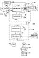
- FIG. 3is a schematic block diagram of a wireless transceiver unit and a wireless base unit of the wireless communication system of FIG. 1 ;
- FIG. 4is a flowchart describing a polling method for use by the wireless base unit
- FIG. 5is a flowchart describing a polling method for use by the wireless transceiver unit which is associated with the flowchart of FIG. 4 ;
- FIG. 6is a flowchart describing another polling method for use by the wireless base unit, which involves detection of a problem or failure;
- FIG. 7is a flowchart describing another polling method for use by the wireless base unit, which involves a communication failure over a data traffic channel;
- FIG. 8is a flowchart describing another polling method for use by the wireless base unit, which involves polling multiple transceiver units simultaneously;
- FIG. 9is a flowchart describing another polling method for use by the wireless transceiver unit, which is associated with the flowchart of FIG. 8 .
- FIG. 1is an illustrative representation of a wireless communication system 100 .
- Wireless communication system 100includes at least one wireless base unit 106 having one or more antennas 108 , and a plurality of remote units 102 (“RUs” or “wireless transceiver units”), such as a wireless transceiver unit 104 .
- Wireless base unit 106 and wireless transceiver units 102communicate via radio frequency (RF) signals, such as RF signals 110 between wireless base unit 106 and wireless transceiver unit 104 .
- RFradio frequency
- Wireless communication system 100can make use of a number of additional different communication techniques, such as frequency division multiplexing (FDM) or orthogonal frequency division multiplexing (OFDM).
- FDMfrequency division multiplexing
- OFDMorthogonal frequency division multiplexing
- wireless communication system 100is a fixed wireless system (FWS), where wireless base unit 106 provides telephone and high-speed data communication to each one of a number of fixed-location subscribers equipped with a wireless transceiver unit (e.g., at home residences).
- wireless communication system 100is a Personal Communication System (PCS) Wireless Access Network (PWAN).
- PCSPersonal Communication System
- PWANWireless Access Network
- Wireless communication link 110includes a plurality of channels available between wireless base unit 106 and wireless transceiver units 102 .
- the plurality of channelsinclude one or more control channels, one or more voice traffic channels, and one or more data traffic channels.
- Voice traffic channelsare utilized for bi-directional communication of voice signals
- data traffic channelsare utilized for bi-directional communication of high speed data, such as Internet data.
- Each voice traffic channelis dedicated to a voice communication call upon assignment (“circuit-switched” type), whereas each data traffic channel is available for use by multiple transceiver units using a data packet protocol (“packet-switched” type).
- Voice traffic channelsare assigned and active only during voice calls, whereas data traffic channels are typically always active.
- each channelcan be identified by a unique combination of frequency and time slots. If there are sixteen frequency slots and eight time slots, for example, one traffic channel may be identified by frequency slot three and time slot seven, another traffic channel may be identified by frequency slot three and time slot two, and even another traffic channel may be identified by frequency slot five and time slot six, etc.
- FIG. 3is a schematic block diagram of wireless transceiver unit 104 and wireless base unit 106 of wireless communication system 100 of FIG. 1 .
- Wireless transceiver unit 104includes a controller 302 , a wireless transceiver 304 , an antenna 306 , power management circuitry 308 , and battery backup circuitry 310 .
- Wireless transceiver unit 104also has an energy source interface 350 , a telephone interface 352 , and a computer interface 354 .
- Energy source interface 350is adapted for coupling to an energy source 316 that provides electrical power to wireless transceiver unit 104 .
- Telephone interface 352is used for receiving and sending voice signals 312 of a telephone or voice communication call.
- Computer interface 354is adapted for coupling to a personal computer (PC) 314 or other computer device to facilitate communication of high speed data (such as Internet data).
- PCpersonal computer
- Energy source 316may be, for example, an alternating current (AC) source provided from an electrical outlet of a home residence.
- power management circuitry 308provides conventional AC to direct current (DC) conversion.
- Power management circuitry 308receives the electrical energy and provides it in appropriate form to controller 302 and wireless transceiver 304 for electrically powering such circuitry. If energy source 316 becomes unavailable to wireless transceiver unit 104 for some reason (e.g., power outage, plug is pulled, etc.), power management circuitry 308 provides a switching function so that electrical energy is provided from battery backup circuitry 310 .
- Battery backup circuitry 310includes, for example, an interface (not visible) for coupling to one or more battery cells, such as off-the-shelf DC batteries.
- wireless base unit 106includes a controller 318 , a wireless transceiver 320 , and an antenna 322 .
- An operator terminal 324such as a PC, may be coupled to wireless base unit 106 to access information from a wireless transceiver unit via polling methods. Operator terminal 324 may be part of a network operating center.
- Wireless base unit 106is also coupled to a Public Switched Telephone Network (PSTN) 326 and, for access to the Internet 330 , an Internet Service Provider (ISP) 328 .
- PSTNPublic Switched Telephone Network
- ISPInternet Service Provider
- Wireless transceiver unit 104 and wireless base unit 106help facilitate telephone or voice calls for a user over PSTN 326 .
- wireless transceiver unit 104 and wireless base unit 106help facilitate data communications for PC 314 , which may access one or more servers, such as a server 332 , available over the Internet 330 .
- outbound voice signals spoken by a userare received at controller 302 , coded and modulated, and transmitted from transceiver 304 and antenna 306 via RF communication signals.
- the RF signalsare transmitted over one of the dedicated voice traffic channels, received at wireless base unit 106 , demodulated and decoded to reproduce the voice signals, and routed accordingly over PSTN 326 to another subscriber.
- inbound voice signalsare received over PSTN 326 by controller 318 , coded and modulated, and transmitted from transceiver 320 and antenna 322 via RF communication signals.
- These RF signalsare transmitted over one of the dedicated voice traffic channels, received by wireless transceiver unit 104 at antenna 306 and wireless transceiver 304 , demodulated and decoded to reproduce the voice signals for the user to listen to.
- outbound data packets from PC 314are received at controller 302 , coded, modulated, and transmitted from transceiver 304 and antenna 306 via RF communication signals.
- the RF signalsare transmitted over one of the data traffic channels.
- These RF communication signalsare received at wireless base unit 106 , demodulated, and decoded to reproduce the data packets.
- These data packetsare routed accordingly to over the Internet 330 to server 332 via ISP 328 .
- inbound data packetsare received from server 332 at controller 318 , coded, modulated, and transmitted from transceiver 320 and antenna 322 via RF communication signals.
- RF signalsare transmitted over a data traffic channel (each of which are shared by multiple transceiver units), received by wireless transceiver unit 104 at antenna 306 and wireless transceiver 304 , demodulated, and decoded to reproduce the data packets.
- the destination addressesmust match that assigned to PC 314 for PC 314 to receive the data packets.
- the data traffic channelis typically always active and wireless transceiver unit 104 must continuously monitor such channel to receive its data packets.
- wireless base unit 106performs “polling” methods with the plurality of wireless transceiver units 102 .
- Pollingis performed to obtain information from wireless remote units 102 to ensure that devices are operating or operating properly, in accordance with some predefined specification. Polling may also be performed to obtain information to facilitate subscriber services, for example, to maintain event logs.
- the methods described hereinmay be embodied and implemented in wireless transceiver unit 104 and wireless base unit 106 of FIG. 1 (as well as other transceiver and base units) in connection with software using software components 200 shown in FIG. 2 .
- the softwaremay be embedded in or stored on a disk 202 or memory 204 , executable on a computer 206 or a processor 208 .
- the inventive featuresmay exist in a signal-bearing medium which embodies a program of machine-readable instructions executable by a processing apparatus which perform the methods.
- the information for which polling is performedmay be any suitable information, such as, for example, status information, configuration information, or call record information.
- Status informationmay be or include, for example, mere acknowledgement, operating condition information, operating mode information, previous usage information, etc.
- Configuration informationmay be or include, for example, reception and transmission parameters for the wireless transceiver unit.
- Configuration informationis typically preprogrammed into and may be unique to each wireless transceiver unit. More particularly, configuration information is typically programmed into an Electrically Erasable/Programmable Read-Only Memory (EEPROM) (not shown) coupled to controller 302 ( FIG. 3 ).
- EEPROMElectrically Erasable/Programmable Read-Only Memory
- Call record informationmay be or include, for example, an identification of a plurality of telephone calls made and/or received over a period of time, timestamps of the previous calls, durations of the previous calls, the number of previous calls, etc.
- a wireless base unitpolls one or more wireless transceiver units with use of what is referred to as an information request message.
- an information request messagemerely instructs or requests the sending of information.
- an information request messagemay include data indicative of a particular information type.
- the information typesmay include a status type, a configuration data type, and a call record type.
- a wireless transceiver unitUpon receipt of an information request message, a wireless transceiver unit reads the data indicative of the particular type, and selects and/or generates and sends the appropriate information corresponding to that type. The wireless transceiver unit may send all of the information associated with the information type. Each information type, however, may be further divided into subtypes.
- the subtypesmay be a call identification type, a call timestamp type, a call duration type, a call number type, etc., each corresponding to particular call record information previously mentioned above.
- a wireless transceiver unitupon receipt of an information request message, a wireless transceiver unit reads the data indicative of the particular information type and subtype, and selects and/or generates and sends only the information corresponding to that subtype within the type.
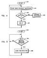
- FIG. 4is a flowchart describing a general polling method for use by wireless base unit 106 of FIG. 1 .
- wireless base unit 106sends an information request message that is intended for receipt by wireless transceiver unit 104 (step 404 ).
- Wireless base unit 106waits for a response at step 406 . If no response is received over some predetermined time period, wireless base unit 106 reports the lack of response to, for example, a database or operator terminal 324 . If a response is received at step 406 , wireless base unit 106 delays for some predetermined time period (step 410 ).
- wireless base unit 106Upon expiration of the time period, wireless base unit 106 repeats the process beginning at step 404 such that polling is performed on a periodic basis for one or more wireless transceiver units. From the viewpoint of wireless transceiver unit 104 , and beginning at a start block 502 of FIG. 5 , wireless transceiver unit 104 waits to receive the information request message from wireless base unit 106 (step 504 ). Upon receipt of such message, wireless transceiver unit 104 selects the appropriate information and sends it to wireless base unit 106 (step 506 ). This process repeats for each information request message sent from wireless base unit 106 , such that polling is performed on a periodic basis For example, the polling may be performed for one or more wireless transceiver units (sequentially or simultaneously) every five minutes.
- the information request messagemay include an information type and/or subtype as described above, where wireless transceiver unit 104 must select from several information to send in accordance with the type and/or subtype.
- any suitable type of informationmay be obtained during such polling.
- wireless base unit 106polls for status information.
- wireless transceiver unit 104may store call record information as previously described. This information may be obtained periodically for comparison and updating of call information stored in a database accessible to wireless base unit 106 .
- pollingmay be performed on a periodic basis to monitor the status of a number of different wireless transceiver units.
- the pollingneed not be “periodic” in a strict sense, however; the polling need only be performed on some regular timed basis.
- operator terminal 324may initiate an “ad hoc” poll when needed.
- operator terminal 324sends a message to wireless base unit 106 that causes it to poll a particular wireless base unit for particular information (e.g., using type/sub-type).
- a single pollis performed per request; that is, no periodic polling is performed.
- This ad hoc pollingmay be used, for example, to obtain configuration information of a wireless transceiver unit that is not operating properly.
- new configuration informationmay be obtained by the network operating center where wireless transceiver unit 104 is reprogrammed “over-the-air” to correct the problem.
- Ad hoc pollingmay also be employed in combination with the periodic polling described in relation to FIGS. 4 and 5 .
- wireless base unit 106may use a Common Link channel (CLC) to send the message and a Solicited Common Access channel (S-CAC) to receive the information, such that a single transceiver unit is polled.
- CLCCommon Link channel
- S-CACSolicited Common Access channel
- wireless base unit 106may use a Broadcast Control channel (BRC) to send the message and an Unsolicited Common Access channel (U-CAC) to receive the information, such that multiple transceiver units are simultaneously polled.
- BRCBroadcast Control channel
- U-CACUnsolicited Common Access channel
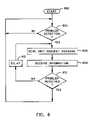
- FIG. 6is a flowchart describing another polling method for use by wireless base unit 106 .
- Wireless base unit 106detects a problem within the system (step 604 ).
- wireless base unit 106initiates the polling process, sending an information request message (step 606 ), receiving information (if at all) (step 608 ), and delaying for a predetermined time period (step 612 ) before repeating the sending and repeating.
- the problem detectedmay be, for example, a communication failure or a power failure. If it is detected that the problem has been corrected (step 610 ), then polling ceases where wireless base unit 106 discontinues the sending of information request messages.
- the methodis repeatable, beginning again at step 604 .
- a communication failuremay occur, for example, when high speed data traffic cannot be (accurately) detected over the data traffic channel.
- controller 318detects a communication failure and, in response, the polling is initiated.
- a power failuremay occur when energy source 316 is unavailable to wireless transceiver unit 104 .
- power management circuitry 308switches battery backup circuitry 310 to electrically power wireless transceiver unit 104 for seamless operation.
- Controller 302detects the loss of this primary energy source 316 and, in response, sends a message to wireless base unit 106 indicating the same.
- Wireless base unit 106receives and detects this problem message and, in response, the polling is initiated.
- wireless units 104 and 106tear down the established data traffic channel after the power failure is detected.
- a data traffic channelis normally maintained by each unit by sending “keep alive” messages back and forth to one another over the data traffic channel. In tearing down the data traffic channel, then, these messages are no longer sent nor received. Voice communication, however, may still be advantageously maintained even though the data traffic channel is torn down.
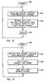
- FIG. 7is a flowchart describing a polling method which relates to the detection of a communication failure over the data traffic channel.
- wireless base unit 106detects a communication problem with wireless transceiver unit 104 over a data traffic channel (step 704 ).
- wireless base unit 106attempts to reestablish data traffic communications with wireless transceiver unit 104 (step 706 ).
- step 708If communication is not successfully reestablished (step 708 ), periodic polling is initiated with wireless transceiver unit 104 , where wireless base unit 106 sends an information request message to wireless transceiver unit 104 over a control channel (step 712 ), receives information from wireless transceiver unit 104 (step 714 ), and delays some predetermined time period (step 718 ) before sending additional information request messages. If the problem is resolved (step 716 ), the process repeats as shown beginning at step 704 .
- FIGS. 8 and 9are flowcharts describing polling methods which involve the simultaneously polling of a plurality of wireless transceiver units.
- FIG. 8corresponds to steps performed at a wireless base unit
- FIG. 9corresponds to steps performed at each wireless transceiver unit.
- wireless base unit 106sends a single information request message over a broadcast channel (step 804 ).
- This channelmay be what is known as a Broadcast channel or BRC. Since it is sent over the broadcast channel, the message is intended for receipt by each wireless transceiver unit 102 that wireless base unit 106 serves.
- BRCBroadcast channel
- wireless base unit 106receives information from multiple wireless transceiver units at random points in time over a channel that is shared amongst the plurality of wireless transceiver units 102 (step 806 ).
- This channelmay be what is known as an Unsolicited Common Access channel or U-CAC.
- Wireless base unit 106might not receive information from those one or more wireless transceiver units having failures or problems.
- Wireless base unit 106may report the lack of response (problem) for each transceiver unit that did not respond.
- wireless base unit 106delays some amount of time (step 808 ) before repeating the process again beginning at step 804 .
- wireless base unit 106delays for some predetermined time so that its polling is performed on a periodic basis.
- wireless transceiver unit 104receives the information request message from the wireless base unit over the broadcast channel (step 904 ).
- Wireless transceiver unit 104delays for some random period of time upon processing the message (step 906 ).
- wireless transceiver unit 104selects a random number using a random number generator and accordingly sets up a timer to expire.
- wireless transceiver unit 104sends information responsive to the information request message over the shared channel (step 908 ). The process repeats for each information request message sent by wireless base unit. It is noted that after step 904 , each wireless transceiver unit 102 does not initially attempt to send its information at the first time available.
- each wireless transceiver unitsends its information after waiting some random amount of time, all wireless transceiver units send the information within some predefined time period. This predefined time period is less than the delay by wireless base unit 106 utilized in step 808 of FIG. 8 .
- each wireless transceiver unit 102feeds a “seed” to its random number generator.
- the seedis preferably an identification number that is unique to the wireless transceiver unit, such as a hardware serial number. This helps ensure that each wireless transceiver unit does not transmit at the same time as any other wireless transceiver unit.
- One polling methodincludes the steps of sending, from a wireless base unit, an information request message; receiving, at a wireless transceiver unit, the information request message; sending, from the wireless transceiver unit, information responsive to the information request message; and receiving, at the wireless base unit, the information.
- the above stepsare preferably repeated on a regular or a periodic basis.
- the information that is polled from the wireless transceiver unitmay be, for example, status information, configuration data, or call record data.
- the polling methodmay be initiated upon detecting a problem or failure, such as detecting a power failure at the wireless transceiver unit or a communication failure over a data traffic channel available between the wireless base and transceiver units. After detecting such a failure, the data traffic channel may be torn down to conserve power at the wireless transceiver unit.
- the polling methodsmay also involve sending an information request message over a broadcast channel, such that a plurality of wireless transceiver units are simultaneously polled.
- each wireless transceiver unitdelays a random period of time before sending its information back to the wireless base unit over a channel that is shared amongst the transceiver units to avoid simultaneous transmission.
Landscapes
- Engineering & Computer Science (AREA)
- Computer Networks & Wireless Communication (AREA)
- Signal Processing (AREA)
- Mobile Radio Communication Systems (AREA)
- Small-Scale Networks (AREA)
Abstract
Description
Claims (17)
Priority Applications (2)
| Application Number | Priority Date | Filing Date | Title |
|---|---|---|---|
| US09/597,016US7720468B1 (en) | 1999-06-23 | 2000-06-20 | Polling methods for use in a wireless communication system |
| US12/697,089US8472941B1 (en) | 1999-06-23 | 2010-01-29 | Polling methods for use in a wireless communication system |
Applications Claiming Priority (2)
| Application Number | Priority Date | Filing Date | Title |
|---|---|---|---|
| US14095999P | 1999-06-23 | 1999-06-23 | |
| US09/597,016US7720468B1 (en) | 1999-06-23 | 2000-06-20 | Polling methods for use in a wireless communication system |
Related Child Applications (1)
| Application Number | Title | Priority Date | Filing Date |
|---|---|---|---|
| US12/697,089ContinuationUS8472941B1 (en) | 1999-06-23 | 2010-01-29 | Polling methods for use in a wireless communication system |
Publications (1)
| Publication Number | Publication Date |
|---|---|
| US7720468B1true US7720468B1 (en) | 2010-05-18 |
Family
ID=42166672
Family Applications (2)
| Application Number | Title | Priority Date | Filing Date |
|---|---|---|---|
| US09/597,016Expired - LifetimeUS7720468B1 (en) | 1999-06-23 | 2000-06-20 | Polling methods for use in a wireless communication system |
| US12/697,089Expired - Fee RelatedUS8472941B1 (en) | 1999-06-23 | 2010-01-29 | Polling methods for use in a wireless communication system |
Family Applications After (1)
| Application Number | Title | Priority Date | Filing Date |
|---|---|---|---|
| US12/697,089Expired - Fee RelatedUS8472941B1 (en) | 1999-06-23 | 2010-01-29 | Polling methods for use in a wireless communication system |
Country Status (1)
| Country | Link |
|---|---|
| US (2) | US7720468B1 (en) |
Cited By (8)
| Publication number | Priority date | Publication date | Assignee | Title |
|---|---|---|---|---|
| US7983688B2 (en) | 1999-06-23 | 2011-07-19 | Clearwire Legacy Llc | Establishing a communication channel in a wireless network |
| EP2595424A1 (en)* | 2011-11-18 | 2013-05-22 | Research In Motion Limited | Method and apparatus for controlling data transmission during a circuit switched call |
| US20140179368A1 (en)* | 2012-11-28 | 2014-06-26 | Renewable Edge, Llc | Custom wireless retrofitted solar powered public telephone |
| US8891414B2 (en) | 2000-12-15 | 2014-11-18 | Adaptix, Inc. | Multi-carrier communications with adaptive cluster configuration and switching |
| CN106227626A (en)* | 2016-09-06 | 2016-12-14 | 深圳市金立通信设备有限公司 | The backup method of a kind of communications records and terminal |
| US9614943B1 (en)* | 1996-12-16 | 2017-04-04 | Rekha K. Rao | System to interface internet protocol (IP) based wireless devices with subtasks and channels |
| US10880881B2 (en) | 2018-05-15 | 2020-12-29 | King Fahd University Of Petroleum And Minerals | Systems and methods for collision prevention and power conservation in wireless networks |
| CN112839371A (en)* | 2021-02-24 | 2021-05-25 | 深圳市中电软件有限公司 | Multi-channel time-sharing wireless networking method and system |
Families Citing this family (3)
| Publication number | Priority date | Publication date | Assignee | Title |
|---|---|---|---|---|
| KR101472100B1 (en)* | 2010-12-22 | 2014-12-11 | 주식회사 케이티 | Base station apparatus and data processing method in wireless communication system |
| US9825828B2 (en) | 2014-08-26 | 2017-11-21 | T-Mobile Usa, Inc. | Cross-layer link failure alerts |
| CN109995489A (en)* | 2017-12-29 | 2019-07-09 | 华为技术有限公司 | Method and device for processing initialization signal |
Citations (33)
| Publication number | Priority date | Publication date | Assignee | Title |
|---|---|---|---|---|
| US3688274A (en)* | 1970-12-23 | 1972-08-29 | Ibm | Command retry control by peripheral devices |
| JPS5368103A (en)* | 1976-11-30 | 1978-06-17 | Toshiba Corp | Data transmission system |
| US4266271A (en)* | 1978-10-10 | 1981-05-05 | Chamoff Martin E | Reconfigurable cluster of data-entry terminals |
| US4638428A (en) | 1983-12-14 | 1987-01-20 | Hitachi, Ltd. | Polling control method and system |
| US4882746A (en)* | 1987-03-22 | 1989-11-21 | Masatoshi Shimada | Cordless telephone system |
| US5289160A (en)* | 1991-09-30 | 1994-02-22 | Fiorletta Carl A | Tire pressure monitoring system |
| US5315636A (en)* | 1991-06-28 | 1994-05-24 | Network Access Corporation | Personal telecommunications system |
| US5410737A (en)* | 1992-04-27 | 1995-04-25 | American Pcs L.P. | Frequency agile sharing technology (FAST) for a personal communications service system |
| US5483676A (en) | 1988-08-04 | 1996-01-09 | Norand Corporation | Mobile radio data communication system and method |
| US5526357A (en)* | 1991-08-16 | 1996-06-11 | Pinpoint Communications, Inc. | Communication system and method for determining the location of a transponder unit |
| US5570389A (en)* | 1994-06-30 | 1996-10-29 | Compaq Computer Corporation | Method for reliable exchange of modem handshaking information over a cellular radio carrier |
| US5600635A (en)* | 1994-04-07 | 1997-02-04 | Matsushita Electric Industrial Co., Ltd. | Caller personal station equipped with simultaneous call function and multicast communication function and corresponding receiver personal station, and cell station and corresponding receiver personal station |
| US5697059A (en) | 1994-05-19 | 1997-12-09 | Airnet Communications Corp. | System for dynamically allocating channels among base stations in a wireless communication system |
| US5749052A (en)* | 1995-05-24 | 1998-05-05 | Tele Digital Development, Inc. | Cellular telephone management system |
| US5809311A (en)* | 1994-07-14 | 1998-09-15 | Dell U.S.A., L.P. | System and method for providing centralized backup power in a computer system |
| US5838774A (en) | 1996-07-01 | 1998-11-17 | Bellsouth Corporation | Telephone polling method |
| US5844473A (en)* | 1995-04-12 | 1998-12-01 | Products Research, Inc. | Method and apparatus for remotely collecting operational information of a mobile vehicle |
| US5907491A (en) | 1996-08-23 | 1999-05-25 | Csi Technology, Inc. | Wireless machine monitoring and communication system |
| US5937358A (en)* | 1995-09-26 | 1999-08-10 | Hani-Prolectron Ag | Method and device for radio communication in traffic guidance systems |
| US6014374A (en)* | 1985-03-20 | 2000-01-11 | Interdigital Technology Corporation | Subscriber RF telephone system for providing multiple speech and/or data signals simultaneously over either a single or a plurality of RF channels |
| US6040786A (en)* | 1998-01-16 | 2000-03-21 | Mitsubishi Denki Kabushiki Kaisha | Recognition system and recognition method for non-contact IC cards |
| US6058420A (en)* | 1998-02-27 | 2000-05-02 | Netsolve, Inc. | Alarm server systems, apparatus, and processes |
| US6108785A (en)* | 1997-03-31 | 2000-08-22 | Intel Corporation | Method and apparatus for preventing unauthorized usage of a computer system |
| US6275497B1 (en) | 1997-02-10 | 2001-08-14 | Hybrid Networks, Inc. | Method and apparatus for controlling communication channels using contention and polling schemes |
| US6301514B1 (en)* | 1996-08-23 | 2001-10-09 | Csi Technology, Inc. | Method and apparatus for configuring and synchronizing a wireless machine monitoring and communication system |
| US6347092B1 (en)* | 1998-03-16 | 2002-02-12 | Fujitsu Limited | Time division multiple access communication system, signal receiving method in time division multiple access communication system, and center unit for use in time division multiple access communication system |
| US6349102B1 (en)* | 1997-06-09 | 2002-02-19 | Fujitsu Limited | Data transmission method by polling and terminal apparatus for use in the method |
| US6480505B1 (en)* | 1999-12-06 | 2002-11-12 | Telefonaktiebolaget Lm Ericsson (Publ) | Batched fair exhaustive polling scheduler |
| US6567386B1 (en)* | 1998-02-27 | 2003-05-20 | Sony Corporation | Polling control method, transmission control apparatus and transmission apparatus |
| US6594284B1 (en)* | 1998-09-16 | 2003-07-15 | Cirrus Logic, Inc. | Network synchronization |
| US6885862B1 (en)* | 1999-04-30 | 2005-04-26 | Harris Canada, Inc. | Wireless subscriber terminal programming using a broadcast control channel |
| US6952420B1 (en) | 1999-10-18 | 2005-10-04 | Paradyne Corporation | System and method for polling devices in a network system |
| US7085553B1 (en)* | 1995-08-31 | 2006-08-01 | Oracle International Corporation | Data communication protocols for a mobile-based client-server system over a wireless network |
Family Cites Families (5)
| Publication number | Priority date | Publication date | Assignee | Title |
|---|---|---|---|---|
| US5377232A (en)* | 1992-01-09 | 1994-12-27 | Cellnet Data Systems, Inc. | Frequency synchronized bidirectional radio system |
| US5361399A (en)* | 1992-06-02 | 1994-11-01 | Pagemart, Inc. | Adaptive communication system for transmitting between base stations and portable transceivers via different data rate communication links |
| US5588005A (en)* | 1995-06-07 | 1996-12-24 | General Electric Company | Protocol and mechanism for primary and mutter mode communication for asset tracking |
| JPH10303796A (en) | 1997-04-30 | 1998-11-13 | Japan Radio Co Ltd | Polling method |
| US6324515B1 (en)* | 1998-06-02 | 2001-11-27 | Nortel Networks Limited | Method and apparatus for asymmetric communication of compressed speech |
- 2000
- 2000-06-20USUS09/597,016patent/US7720468B1/ennot_activeExpired - Lifetime
- 2010
- 2010-01-29USUS12/697,089patent/US8472941B1/ennot_activeExpired - Fee Related
Patent Citations (33)
| Publication number | Priority date | Publication date | Assignee | Title |
|---|---|---|---|---|
| US3688274A (en)* | 1970-12-23 | 1972-08-29 | Ibm | Command retry control by peripheral devices |
| JPS5368103A (en)* | 1976-11-30 | 1978-06-17 | Toshiba Corp | Data transmission system |
| US4266271A (en)* | 1978-10-10 | 1981-05-05 | Chamoff Martin E | Reconfigurable cluster of data-entry terminals |
| US4638428A (en) | 1983-12-14 | 1987-01-20 | Hitachi, Ltd. | Polling control method and system |
| US6014374A (en)* | 1985-03-20 | 2000-01-11 | Interdigital Technology Corporation | Subscriber RF telephone system for providing multiple speech and/or data signals simultaneously over either a single or a plurality of RF channels |
| US4882746A (en)* | 1987-03-22 | 1989-11-21 | Masatoshi Shimada | Cordless telephone system |
| US5483676A (en) | 1988-08-04 | 1996-01-09 | Norand Corporation | Mobile radio data communication system and method |
| US5315636A (en)* | 1991-06-28 | 1994-05-24 | Network Access Corporation | Personal telecommunications system |
| US5526357A (en)* | 1991-08-16 | 1996-06-11 | Pinpoint Communications, Inc. | Communication system and method for determining the location of a transponder unit |
| US5289160A (en)* | 1991-09-30 | 1994-02-22 | Fiorletta Carl A | Tire pressure monitoring system |
| US5410737A (en)* | 1992-04-27 | 1995-04-25 | American Pcs L.P. | Frequency agile sharing technology (FAST) for a personal communications service system |
| US5600635A (en)* | 1994-04-07 | 1997-02-04 | Matsushita Electric Industrial Co., Ltd. | Caller personal station equipped with simultaneous call function and multicast communication function and corresponding receiver personal station, and cell station and corresponding receiver personal station |
| US5697059A (en) | 1994-05-19 | 1997-12-09 | Airnet Communications Corp. | System for dynamically allocating channels among base stations in a wireless communication system |
| US5570389A (en)* | 1994-06-30 | 1996-10-29 | Compaq Computer Corporation | Method for reliable exchange of modem handshaking information over a cellular radio carrier |
| US5809311A (en)* | 1994-07-14 | 1998-09-15 | Dell U.S.A., L.P. | System and method for providing centralized backup power in a computer system |
| US5844473A (en)* | 1995-04-12 | 1998-12-01 | Products Research, Inc. | Method and apparatus for remotely collecting operational information of a mobile vehicle |
| US5749052A (en)* | 1995-05-24 | 1998-05-05 | Tele Digital Development, Inc. | Cellular telephone management system |
| US7085553B1 (en)* | 1995-08-31 | 2006-08-01 | Oracle International Corporation | Data communication protocols for a mobile-based client-server system over a wireless network |
| US5937358A (en)* | 1995-09-26 | 1999-08-10 | Hani-Prolectron Ag | Method and device for radio communication in traffic guidance systems |
| US5838774A (en) | 1996-07-01 | 1998-11-17 | Bellsouth Corporation | Telephone polling method |
| US5907491A (en) | 1996-08-23 | 1999-05-25 | Csi Technology, Inc. | Wireless machine monitoring and communication system |
| US6301514B1 (en)* | 1996-08-23 | 2001-10-09 | Csi Technology, Inc. | Method and apparatus for configuring and synchronizing a wireless machine monitoring and communication system |
| US6275497B1 (en) | 1997-02-10 | 2001-08-14 | Hybrid Networks, Inc. | Method and apparatus for controlling communication channels using contention and polling schemes |
| US6108785A (en)* | 1997-03-31 | 2000-08-22 | Intel Corporation | Method and apparatus for preventing unauthorized usage of a computer system |
| US6349102B1 (en)* | 1997-06-09 | 2002-02-19 | Fujitsu Limited | Data transmission method by polling and terminal apparatus for use in the method |
| US6040786A (en)* | 1998-01-16 | 2000-03-21 | Mitsubishi Denki Kabushiki Kaisha | Recognition system and recognition method for non-contact IC cards |
| US6567386B1 (en)* | 1998-02-27 | 2003-05-20 | Sony Corporation | Polling control method, transmission control apparatus and transmission apparatus |
| US6058420A (en)* | 1998-02-27 | 2000-05-02 | Netsolve, Inc. | Alarm server systems, apparatus, and processes |
| US6347092B1 (en)* | 1998-03-16 | 2002-02-12 | Fujitsu Limited | Time division multiple access communication system, signal receiving method in time division multiple access communication system, and center unit for use in time division multiple access communication system |
| US6594284B1 (en)* | 1998-09-16 | 2003-07-15 | Cirrus Logic, Inc. | Network synchronization |
| US6885862B1 (en)* | 1999-04-30 | 2005-04-26 | Harris Canada, Inc. | Wireless subscriber terminal programming using a broadcast control channel |
| US6952420B1 (en) | 1999-10-18 | 2005-10-04 | Paradyne Corporation | System and method for polling devices in a network system |
| US6480505B1 (en)* | 1999-12-06 | 2002-11-12 | Telefonaktiebolaget Lm Ericsson (Publ) | Batched fair exhaustive polling scheduler |
Non-Patent Citations (1)
| Title |
|---|
| JP10303796A Japan Radio Co LTD, Nov. 1998.* |
Cited By (18)
| Publication number | Priority date | Publication date | Assignee | Title |
|---|---|---|---|---|
| US9614943B1 (en)* | 1996-12-16 | 2017-04-04 | Rekha K. Rao | System to interface internet protocol (IP) based wireless devices with subtasks and channels |
| US7983688B2 (en) | 1999-06-23 | 2011-07-19 | Clearwire Legacy Llc | Establishing a communication channel in a wireless network |
| US9191138B2 (en) | 2000-12-15 | 2015-11-17 | Adaptix, Inc. | OFDMA with adaptive subcarrier-cluster configuration and selective loading |
| US9203553B1 (en) | 2000-12-15 | 2015-12-01 | Adaptix, Inc. | OFDMA with adaptive subcarrier-cluster configuration and selective loading |
| US8934445B2 (en) | 2000-12-15 | 2015-01-13 | Adaptix, Inc. | Multi-carrier communications with adaptive cluster configuration and switching |
| US8934375B2 (en) | 2000-12-15 | 2015-01-13 | Adaptix, Inc. | OFDMA with adaptive subcarrier-cluster configuration and selective loading |
| US8958386B2 (en) | 2000-12-15 | 2015-02-17 | Adaptix, Inc. | Multi-carrier communications with adaptive cluster configuration and switching |
| US8964719B2 (en) | 2000-12-15 | 2015-02-24 | Adaptix, Inc. | OFDMA with adaptive subcarrier-cluster configuration and selective loading |
| US9344211B2 (en) | 2000-12-15 | 2016-05-17 | Adaptix, Inc. | OFDMA with adaptive subcarrier-cluster configuration and selective loading |
| US8891414B2 (en) | 2000-12-15 | 2014-11-18 | Adaptix, Inc. | Multi-carrier communications with adaptive cluster configuration and switching |
| US9210708B1 (en) | 2000-12-15 | 2015-12-08 | Adaptix, Inc. | OFDMA with adaptive subcarrier-cluster configuration and selective loading |
| US9219572B2 (en) | 2000-12-15 | 2015-12-22 | Adaptix, Inc. | OFDMA with adaptive subcarrier-cluster configuration and selective loading |
| EP2595424A1 (en)* | 2011-11-18 | 2013-05-22 | Research In Motion Limited | Method and apparatus for controlling data transmission during a circuit switched call |
| US20140179368A1 (en)* | 2012-11-28 | 2014-06-26 | Renewable Edge, Llc | Custom wireless retrofitted solar powered public telephone |
| US9614398B2 (en)* | 2012-11-28 | 2017-04-04 | Renewable Edge, Llc | Custom wireless retrofitted solar powered public telephone |
| CN106227626A (en)* | 2016-09-06 | 2016-12-14 | 深圳市金立通信设备有限公司 | The backup method of a kind of communications records and terminal |
| US10880881B2 (en) | 2018-05-15 | 2020-12-29 | King Fahd University Of Petroleum And Minerals | Systems and methods for collision prevention and power conservation in wireless networks |
| CN112839371A (en)* | 2021-02-24 | 2021-05-25 | 深圳市中电软件有限公司 | Multi-channel time-sharing wireless networking method and system |
Also Published As
| Publication number | Publication date |
|---|---|
| US8472941B1 (en) | 2013-06-25 |
Similar Documents
| Publication | Publication Date | Title |
|---|---|---|
| US8472941B1 (en) | Polling methods for use in a wireless communication system | |
| AU2005293152B2 (en) | Method and apparatus for power saving in wireless systems | |
| RU2336653C2 (en) | Continuous wireless communication over internet protocol | |
| CN1330199C (en) | Radio base station, radio communication system, communication control method of cell station | |
| KR100728546B1 (en) | Method and system for maintaining a wireless data connection | |
| US20030125087A1 (en) | Wireless base station device, wireless communication system, and communication control method | |
| US20020022455A1 (en) | Method for reducing the power consumption of a wireless terminal, a communication system and a wireless terminal | |
| CN101730090B (en) | Method and equipment for releasing IP addresses by DHCP server | |
| JP2005505215A (en) | Contact management of mobile communication devices in wireless packet switched networks | |
| US20080009307A1 (en) | System and method for optimized wireless client communication | |
| EP0737018B1 (en) | Method for sharing a single radio channel in a cellular network | |
| TWI482508B (en) | Method of multi-carrier operational modes in wireless communications protocol, method of initializing a mobile station in order to prepare for multi-carrier operation in same, and carrier management method in same | |
| KR19990063802A (en) | How to Control Temporary Device Identifier Message Responses | |
| CN115767445B (en) | Bluetooth broadcast two-way communication method, device, electronic device and storage medium | |
| US9906426B2 (en) | Method of accelerating control link loss detection | |
| JP2011015273A (en) | Content distribution system | |
| EP1134950B1 (en) | Improvements to control system for network servers | |
| JP4071915B2 (en) | Multicast service providing system and method, radio terminal and information distribution apparatus | |
| CN101369964B (en) | Method for accelerating control link loss detection | |
| KR100342528B1 (en) | Method for managing ppp resources of simple ip subscriber | |
| CN114040391A (en) | Network distribution method of intelligent equipment and router | |
| WO2023186713A1 (en) | Partially connected devices | |
| JP2002077453A (en) | Communication line connection method for connection type communication system, user station and center station | |
| KR20080044385A (en) | Method and system for providing SD services to mobile stations in dormant state |
Legal Events
| Date | Code | Title | Description |
|---|---|---|---|
| AS | Assignment | Owner name:AT&T WIRELESS SERVICES, INC.,WASHINGTON Free format text:ASSIGNMENT OF ASSIGNORS INTEREST;ASSIGNORS:HONG, LIANG A.;MOINZADEH, KAMYAR;NGUYEN, LUONG P.;SIGNING DATES FROM 20000815 TO 20001101;REEL/FRAME:011336/0040 | |
| AS | Assignment | Owner name:CLEARWIRE CORPORATION,WASHINGTON Free format text:ASSIGNMENT OF ASSIGNORS INTEREST;ASSIGNOR:AT&T WIRELESS SERVICES, INC.;REEL/FRAME:015177/0566 Effective date:20040909 Owner name:CLEARWIRE CORPORATION, WASHINGTON Free format text:ASSIGNMENT OF ASSIGNORS INTEREST;ASSIGNOR:AT&T WIRELESS SERVICES, INC.;REEL/FRAME:015177/0566 Effective date:20040909 | |
| AS | Assignment | Owner name:MORGAN STANLEY & CO., INC., AS COLLATERAL AGENT,NE Free format text:SECURITY AGREEMENT;ASSIGNOR:CLEARWIRE CORPORATION;REEL/FRAME:019550/0454 Effective date:20070703 Owner name:MORGAN STANLEY & CO., INC., AS COLLATERAL AGENT, N Free format text:SECURITY AGREEMENT;ASSIGNOR:CLEARWIRE CORPORATION;REEL/FRAME:019550/0454 Effective date:20070703 | |
| AS | Assignment | Owner name:CLEARWIRE SUB LLC,WASHINGTON Free format text:MERGER;ASSIGNOR:CLEARWIRE CORPORATION;REEL/FRAME:022449/0723 Effective date:20081201 Owner name:CLEARWIRE LEGACY LLC,WASHINGTON Free format text:CHANGE OF NAME;ASSIGNOR:CLEARWIRE SUB LLC;REEL/FRAME:022449/0730 Effective date:20081201 Owner name:CLEARWIRE SUB LLC, WASHINGTON Free format text:MERGER;ASSIGNOR:CLEARWIRE CORPORATION;REEL/FRAME:022449/0723 Effective date:20081201 Owner name:CLEARWIRE LEGACY LLC, WASHINGTON Free format text:CHANGE OF NAME;ASSIGNOR:CLEARWIRE SUB LLC;REEL/FRAME:022449/0730 Effective date:20081201 | |
| AS | Assignment | Owner name:WILMINGTON TRUST FSB, AS COLLATERAL AGENT,MINNESOT Free format text:SECURITY AGREEMENT;ASSIGNORS:CLEARWIRE LEGACY LLC;CLEAR WIRELESS LLC;REEL/FRAME:023574/0539 Effective date:20091124 Owner name:WILMINGTON TRUST FSB, AS COLLATERAL AGENT, MINNESO Free format text:SECURITY AGREEMENT;ASSIGNORS:CLEARWIRE LEGACY LLC;CLEAR WIRELESS LLC;REEL/FRAME:023574/0539 Effective date:20091124 | |
| STCF | Information on status: patent grant | Free format text:PATENTED CASE | |
| AS | Assignment | Owner name:WILMINGTON TRUST FSB, MINNESOTA Free format text:SECURITY INTEREST;ASSIGNORS:CLEARWIRE COMMUNICATIONS LLC;CLEARWIRE FINANCE, INC.;REEL/FRAME:025042/0779 Effective date:20100428 | |
| AS | Assignment | Owner name:WILMINGTON TRUST FSB, AS COLLATERAL AGENT, MINNESO Free format text:SECOND LIEN PATENT SECURITY AGREEMENT;ASSIGNORS:CLEARWIRE LEGACY LLC;CLEAR WIRELESS LLC;REEL/FRAME:025473/0569 Effective date:20101209 | |
| AS | Assignment | Owner name:CLEARWIRE IP HOLDINGS LLC, WASHINGTON Free format text:ASSIGNMENT OF ASSIGNORS INTEREST;ASSIGNOR:CLEARWIRE COMMUNICATIONS LLC;REEL/FRAME:027134/0855 Effective date:20111026 Owner name:CLEARWIRE COMMUNICATIONS, WASHINGTON Free format text:ASSIGNMENT OF ASSIGNORS INTEREST;ASSIGNOR:CLEARWIRE LEGACY LLC;REEL/FRAME:027132/0233 Effective date:20111026 | |
| AS | Assignment | Owner name:CLEARWIRE CORPORATION, WASHINGTON Free format text:RELEASE BY SECURED PARTY;ASSIGNOR:MORGAN STANLEY & CO. INC.;REEL/FRAME:027584/0572 Effective date:20120112 | |
| FPAY | Fee payment | Year of fee payment:4 | |
| AS | Assignment | Owner name:DEUTSCHE BANK TRUST COMPANY AMERICAS, NEW YORK Free format text:GRANT OF FIRST PRIORITY AND JUNIOR PRIORITY SECURITY INTEREST IN PATENT RIGHTS;ASSIGNOR:CLEARWIRE IP HOLDINGS LLC;REEL/FRAME:041882/0875 Effective date:20170203 | |
| MAFP | Maintenance fee payment | Free format text:PAYMENT OF MAINTENANCE FEE, 8TH YEAR, LARGE ENTITY (ORIGINAL EVENT CODE: M1552) Year of fee payment:8 | |
| AS | Assignment | Owner name:CLEARWIRE IP HOLDINGS LLC, KANSAS Free format text:TERMINATION AND RELEASE OF FIRST PRIORITY AND JUNIOR PRIORITY SECURITY INTEREST IN PATENT RIGHTS;ASSIGNOR:DEUTSCHE BANK TRUST COMPANY AMERICAS;REEL/FRAME:052291/0439 Effective date:20200401 | |
| AS | Assignment | Owner name:DEUTSCHE BANK TRUST COMPANY AMERICAS, NEW YORK Free format text:SECURITY AGREEMENT;ASSIGNORS:T-MOBILE USA, INC.;ISBV LLC;T-MOBILE CENTRAL LLC;AND OTHERS;REEL/FRAME:053182/0001 Effective date:20200401 | |
| AS | Assignment | Owner name:CLEAR WIRELESS LLC, KANSAS Free format text:TERMINATION AND RELEASE OF SECURITY INTEREST IN PATENTS;ASSIGNOR:WILMINGTON TRUST, NATIONAL ASSOCIATION, AS SUCCESSOR BY MERGER TO WILMINGTON TRUST FSB;REEL/FRAME:052312/0970 Effective date:20200331 Owner name:CLEAR WIRELESS LLC, KANSAS Free format text:WILMINGTON TRUST, NATIONAL ASSOCIATION, AS SUCCESSOR BY MERGER TO WILMINGTON TRUST FSB;ASSIGNOR:WILMINGTON TRUST, NATIONAL ASSOCIATION, AS SUCCESSOR BY MERGER TO WILMINGTON TRUST FSB;REEL/FRAME:052312/0975 Effective date:20200331 Owner name:CLEARWIRE LEGACY LLC, KANSAS Free format text:TERMINATION AND RELEASE OF SECURITY INTEREST IN PATENTS;ASSIGNOR:WILMINGTON TRUST, NATIONAL ASSOCIATION, AS SUCCESSOR BY MERGER TO WILMINGTON TRUST FSB;REEL/FRAME:052312/0970 Effective date:20200331 Owner name:CLEARWIRE COMMUNICATIONS LLC, KANSAS Free format text:TERMINATION AND RELEASE OF SECURITY INTEREST IN PATENTS;ASSIGNOR:WILMINGTON TRUST, NATIONAL ASSOCIATION, AS SUCCESSOR BY MERGER TO WILMINGTON TRUST FSB;REEL/FRAME:052312/0970 Effective date:20200331 Owner name:CLEARWIRE FINANCE, INC., KANSAS Free format text:TERMINATION AND RELEASE OF SECURITY INTEREST IN PATENTS;ASSIGNOR:WILMINGTON TRUST, NATIONAL ASSOCIATION, AS SUCCESSOR BY MERGER TO WILMINGTON TRUST FSB;REEL/FRAME:052312/0970 Effective date:20200331 Owner name:CLEARWIRE LEGACY LLC, KANSAS Free format text:WILMINGTON TRUST, NATIONAL ASSOCIATION, AS SUCCESSOR BY MERGER TO WILMINGTON TRUST FSB;ASSIGNOR:WILMINGTON TRUST, NATIONAL ASSOCIATION, AS SUCCESSOR BY MERGER TO WILMINGTON TRUST FSB;REEL/FRAME:052312/0975 Effective date:20200331 Owner name:CLEAR WIRELESS LLC, KANSAS Free format text:TERMINATION AND RELEASE OF SECURITY INTEREST IN PATENTS;ASSIGNOR:WILMINGTON TRUST, NATIONAL ASSOCIATION, AS SUCCESSOR BY MERGER TO WILMINGTON TRUST FSB;REEL/FRAME:053182/0700 Effective date:20200331 Owner name:CLEARWIRE LEGACY LLC, KANSAS Free format text:TERMINATION AND RELEASE OF SECURITY INTEREST IN PATENTS;ASSIGNOR:WILMINGTON TRUST, NATIONAL ASSOCIATION, AS SUCCESSOR BY MERGER TO WILMINGTON TRUST FSB;REEL/FRAME:053182/0700 Effective date:20200331 | |
| AS | Assignment | Owner name:CLEAR WIRELESS LLC, KANSAS Free format text:RELEASE BY SECURED PARTY;ASSIGNOR:WILMINGTON TRUST FSB;REEL/FRAME:053620/0469 Effective date:20200827 Owner name:CLEARWIRE LEGACY LLC, KANSAS Free format text:RELEASE BY SECURED PARTY;ASSIGNOR:WILMINGTON TRUST FSB;REEL/FRAME:053620/0469 Effective date:20200827 Owner name:CLEARWIRE FINANCE,INC., KANSAS Free format text:RELEASE BY SECURED PARTY;ASSIGNOR:WILMINGTON TRUST FSB;REEL/FRAME:053620/0469 Effective date:20200827 Owner name:CLEARWIRE COMMUNICATIONS LLC, KANSAS Free format text:RELEASE BY SECURED PARTY;ASSIGNOR:WILMINGTON TRUST FSB;REEL/FRAME:053620/0469 Effective date:20200827 | |
| MAFP | Maintenance fee payment | Free format text:PAYMENT OF MAINTENANCE FEE, 12TH YEAR, LARGE ENTITY (ORIGINAL EVENT CODE: M1553); ENTITY STATUS OF PATENT OWNER: LARGE ENTITY Year of fee payment:12 | |
| AS | Assignment | Owner name:SPRINT SPECTRUM LLC, KANSAS Free format text:RELEASE BY SECURED PARTY;ASSIGNOR:DEUTSCHE BANK TRUST COMPANY AMERICAS;REEL/FRAME:062595/0001 Effective date:20220822 Owner name:SPRINT INTERNATIONAL INCORPORATED, KANSAS Free format text:RELEASE BY SECURED PARTY;ASSIGNOR:DEUTSCHE BANK TRUST COMPANY AMERICAS;REEL/FRAME:062595/0001 Effective date:20220822 Owner name:SPRINT COMMUNICATIONS COMPANY L.P., KANSAS Free format text:RELEASE BY SECURED PARTY;ASSIGNOR:DEUTSCHE BANK TRUST COMPANY AMERICAS;REEL/FRAME:062595/0001 Effective date:20220822 Owner name:SPRINTCOM LLC, KANSAS Free format text:RELEASE BY SECURED PARTY;ASSIGNOR:DEUTSCHE BANK TRUST COMPANY AMERICAS;REEL/FRAME:062595/0001 Effective date:20220822 Owner name:CLEARWIRE IP HOLDINGS LLC, KANSAS Free format text:RELEASE BY SECURED PARTY;ASSIGNOR:DEUTSCHE BANK TRUST COMPANY AMERICAS;REEL/FRAME:062595/0001 Effective date:20220822 Owner name:CLEARWIRE COMMUNICATIONS LLC, KANSAS Free format text:RELEASE BY SECURED PARTY;ASSIGNOR:DEUTSCHE BANK TRUST COMPANY AMERICAS;REEL/FRAME:062595/0001 Effective date:20220822 Owner name:BOOST WORLDWIDE, LLC, KANSAS Free format text:RELEASE BY SECURED PARTY;ASSIGNOR:DEUTSCHE BANK TRUST COMPANY AMERICAS;REEL/FRAME:062595/0001 Effective date:20220822 Owner name:ASSURANCE WIRELESS USA, L.P., KANSAS Free format text:RELEASE BY SECURED PARTY;ASSIGNOR:DEUTSCHE BANK TRUST COMPANY AMERICAS;REEL/FRAME:062595/0001 Effective date:20220822 Owner name:T-MOBILE USA, INC., WASHINGTON Free format text:RELEASE BY SECURED PARTY;ASSIGNOR:DEUTSCHE BANK TRUST COMPANY AMERICAS;REEL/FRAME:062595/0001 Effective date:20220822 Owner name:T-MOBILE CENTRAL LLC, WASHINGTON Free format text:RELEASE BY SECURED PARTY;ASSIGNOR:DEUTSCHE BANK TRUST COMPANY AMERICAS;REEL/FRAME:062595/0001 Effective date:20220822 Owner name:PUSHSPRING, LLC, WASHINGTON Free format text:RELEASE BY SECURED PARTY;ASSIGNOR:DEUTSCHE BANK TRUST COMPANY AMERICAS;REEL/FRAME:062595/0001 Effective date:20220822 Owner name:LAYER3 TV, LLC, WASHINGTON Free format text:RELEASE BY SECURED PARTY;ASSIGNOR:DEUTSCHE BANK TRUST COMPANY AMERICAS;REEL/FRAME:062595/0001 Effective date:20220822 Owner name:IBSV LLC, WASHINGTON Free format text:RELEASE BY SECURED PARTY;ASSIGNOR:DEUTSCHE BANK TRUST COMPANY AMERICAS;REEL/FRAME:062595/0001 Effective date:20220822 |