US7720226B2 - Private and secure optical communication system using an optical tapped delay line - Google Patents
Private and secure optical communication system using an optical tapped delay lineDownload PDFInfo
- Publication number
- US7720226B2 US7720226B2US10/715,824US71582403AUS7720226B2US 7720226 B2US7720226 B2US 7720226B2US 71582403 AUS71582403 AUS 71582403AUS 7720226 B2US7720226 B2US 7720226B2
- Authority
- US
- United States
- Prior art keywords
- sub
- bands
- band
- optical signal
- imparting
- Prior art date
- Legal status (The legal status is an assumption and is not a legal conclusion. Google has not performed a legal analysis and makes no representation as to the accuracy of the status listed.)
- Active, expires
Links
- 230000003287optical effectEffects0.000titleclaimsabstractdescription62
- 238000004891communicationMethods0.000titledescription8
- 238000000034methodMethods0.000claimsabstractdescription28
- 230000005540biological transmissionEffects0.000claimsabstractdescription14
- 230000003595spectral effectEffects0.000claimsdescription30
- 230000010363phase shiftEffects0.000claimsdescription14
- 230000010354integrationEffects0.000claimsdescription3
- 239000004973liquid crystal related substanceSubstances0.000claimsdescription2
- 239000004065semiconductorSubstances0.000claimsdescription2
- 238000012986modificationMethods0.000claims5
- 230000004048modificationEffects0.000claims5
- 239000000835fiberSubstances0.000description14
- 238000004458analytical methodMethods0.000description2
- 239000011248coating agentSubstances0.000description2
- 238000000576coating methodMethods0.000description2
- 230000000694effectsEffects0.000description2
- 238000005516engineering processMethods0.000description2
- GPXJNWSHGFTCBW-UHFFFAOYSA-NIndium phosphideChemical compound[In]#PGPXJNWSHGFTCBW-UHFFFAOYSA-N0.000description1
- 230000003466anti-cipated effectEffects0.000description1
- 238000003491arrayMethods0.000description1
- 238000006243chemical reactionMethods0.000description1
- 230000001427coherent effectEffects0.000description1
- 230000001934delayEffects0.000description1
- 230000003111delayed effectEffects0.000description1
- 238000001514detection methodMethods0.000description1
- 238000003384imaging methodMethods0.000description1
- GQYHUHYESMUTHG-UHFFFAOYSA-Nlithium niobateChemical compound[Li+].[O-][Nb](=O)=OGQYHUHYESMUTHG-UHFFFAOYSA-N0.000description1
- 239000011159matrix materialSubstances0.000description1
- 239000013307optical fiberSubstances0.000description1
- 238000011084recoveryMethods0.000description1
- 230000008054signal transmissionEffects0.000description1
- 230000003068static effectEffects0.000description1
- 230000009466transformationEffects0.000description1
Images


Classifications
- H—ELECTRICITY
- H04—ELECTRIC COMMUNICATION TECHNIQUE
- H04B—TRANSMISSION
- H04B10/00—Transmission systems employing electromagnetic waves other than radio-waves, e.g. infrared, visible or ultraviolet light, or employing corpuscular radiation, e.g. quantum communication
- H04B10/80—Optical aspects relating to the use of optical transmission for specific applications, not provided for in groups H04B10/03 - H04B10/70, e.g. optical power feeding or optical transmission through water
- H04B10/85—Protection from unauthorised access, e.g. eavesdrop protection
- H—ELECTRICITY
- H04—ELECTRIC COMMUNICATION TECHNIQUE
- H04K—SECRET COMMUNICATION; JAMMING OF COMMUNICATION
- H04K1/00—Secret communication
- H04K1/04—Secret communication by frequency scrambling, i.e. by transposing or inverting parts of the frequency band or by inverting the whole band
Definitions
- the present inventionrelates generally to optical systems, including what may be referred to as optical communications systems, optical telecommunications systems and optical networks, and more particularly to a method and system for information security in an optical transmission system.
- WDMWavelength Division Multiplexing
- Brackett et al in U.S. Pat. No. 4,866,699teaches an analog method of coding and decoding for multi-user communications based on optical frequency domain coding and decoding of coherently related spectral components. Brackett fails to address any secure or privacy communication applications where the spectral components are not coherently related.
- one object in accordance with the present inventionis to improve optical communications security by providing an analog method of protecting transmissions that is lower in cost, volume, weight and/or power, especially at high transmission bit rates.
- the present inventionin a preferred embodiment, provides an analog method and apparatus for effectively protecting electronic communications that may be transmitted, for example, over a fiber optic or free-space network.
- the present inventionmay use a combination of an Optical Tapped Delay Line (OTDL), as disclosed in U.S. Pat. No. 6,608,721 (which patent is incorporated herein by reference), with known methods of altering the properties of an analog signal.
- OTDLOptical Tapped Delay Line
- a privacy systemcan be described as a system where the source signal is sufficiently protected to make unauthorized interception exceptionally difficult for the majority of potential adversaries, but not so difficult as to prevent interception by a sophisticated, well-funded and determined adversary, such as a government.
- a secure systemis one in which the transmitted information signal is well protected against unauthorized intrusion by highly sophisticated adversaries having extensive computing resources.
- the security provided in accordance with the present inventioncan attain many levels of security, from a privacy system to a truly secure system, by, for example: (1) varying the number of sub-bands; (2) changing the analog properties of the sub-bands by altering the phase, introducing time delays, or shifting the originating signal's frequency components; and (3) controlling the periodicity of the changes.
- the rate of signal transmissionalso affects the probability of signal interception. For example, a 10 gigabit per second signal is inherently more difficult to intercept than a 2.5 gigabit per second signal.
- the present inventionin a preferred embodiment, is capable of protecting optical signals at bit rates exceeding 1 gigabit per second.
- a transmission using a preferred embodiment of the present inventionis protected from an attack because any attack requires coherent detection of a large bandwidth of analog data at a high-precision digitization rate, and even if coherently intercepted, the properties of the signal are scrambled to the extent that recovery is virtually impossible.
- an OTDL device with 128 sub-bands and 10 different phase shift combinationsrequires a brute-force attack approaching 10 128 tries to coherently recover the signal, a feat not possible with current analog-to-digital conversion technology combined with the fastest supercomputer. To make interception even less likely, the sub-band distortion pattern can be periodically changed.
- FIG. 1illustrates an example of an Optical Tapped Delay Line (OTDL).
- OTDLOptical Tapped Delay Line
- FIG. 2illustrates an example of an operational side view of an OTDL device.
- FIG. 3illustrates an example of an operational side view of a preferred embodiment of the present invention operating in reflective mode.
- FIG. 4illustrates an example of a signal before, during and after transmission through a preferred embodiment of the present invention.
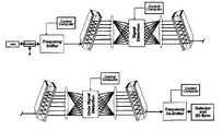
- FIG. 5illustrates an example of a preferred embodiment of the present invention in transmissive mode.
- FIG. 6illustrates an example of an input carrier frequency shifting embodiment of the present invention in reflective mode.
- FIG. 7illustrates an example of an input carrier frequency shifting embodiment of the present invention in transmissive mode.
- FIG. 8illustrates an example of another embodiment of the present invention that uses two OTDL devices to obtain very high resolution sub-bands.
- FIGS. 1 and 2illustrate examples of the previously referenced OTDL device for demultiplexing a multi-channel WDM band into individual channels.
- a detailed explanation of the deviceis provided in U.S. Pat. No. 6,608,721 (incorporated herein by reference), but the operation will be briefly outlined here to facilitate understanding of some preferred embodiments of the invention.
- six collimated input beams 230 a - 230 fenter an Optical Tapped Delay Line (OTDL) 231 .
- the origin of the beamsmay be, for example, the collimated outputs of six optical fibers (not shown) where each fiber typically carries multiple wavelengths.
- a fully reflective coating 232 on plate 235 and a partially reflective coating 236 on plate 237cause each of the input beams entering the device to be multiply reflected within a cavity 233 .
- the various output beamsare then directed to an anamorphic optical system having a cylinder lens 242 and a spherical lens 245 .
- the anamorphic optical system 242 , 245performs the functions of: 1) Fourier transformation of the output of the cavity 231 in the vertical dimension y, and 2) imaging of the output beams of the OTDL 231 in the horizontal dimension x onto an output surface 246 .
- the outputsare imaged on plane 246 with each information-carrying wavelength focused at a specific spot on the plane. By properly placing detectors at plane 246 , each WDM information channel may be detected for further processing.
- FIG. 3illustrates an example of an optical communications system in accordance with a preferred embodiment of the present invention.
- This embodimentincludes a transmitter 50 and a receiver 52 .
- a fiber 56 carrying an information-carrying optical signalis received by the OTDL 58 .
- the lightis processed as described in the explanation for FIGS. 1 and 2 .
- the beamletsexit the OTDL from optical tap locations 54 a to 54 g and a lens system 60 interferes the beamlets onto a planar reflective phase modulator array 62 . Passage through the OTDL 58 and lens 60 to the plane 62 has split the information-carrying optical signal into a number of sub-bands.
- the OTDLcan be designed to output at least hundreds of sub-bands.
- the reflective phase modulator array 62may be implemented in a number of ways, including, but not limited to, a liquid crystal array, a MEMS device, or an array of III-V or II-VI semiconductor devices.
- the speed at which the phase shifting changesmay directly affect the level of security afforded.
- one modulator elementis associated with each sub-band. As each sub-band passes through a modulator element, it is phase shifted in a manner determined by the control computer 64 .
- the mirror part of the modulator array 62reflects the sub-bands back through lens system 60 to tap locations 57 a to 57 g .
- the OTDL 58recombines the taps into an optical signal for retransmission over a fiber optic carrier 76 to the destination.
- the signal from transmitter 50is received by OTDL 72 from fiber 76 .
- the OTDL 72 and lens 70 combinationis identical to the OTDL 58 and lens 60 combination.
- OTDL 72 and lens 70separate the signal into the identical sub-bands created by OTDL 58 and lens 60 .
- the sub-bandsare imaged onto the reflective phase modulator array 68 , with each array element receiving the same sub-band as the corresponding modulator in array 62 .
- the control computer 66causes each sub-band to be phase shifted in the opposite manner as instructed by control computer 64 .
- Each sub-bandis then reflected back through lens system 70 to OTDL 72 which together recombine the sub-bands into a single signal that is output to fiber 74 for further processing or routing.
- the effect of imparting a phase shift to each sub-bandis to introduce distortion. If the amount of distortion is sufficient, the information content becomes undecipherable and security is enhanced.
- the control computer 64instructs the modulator array how to modify the phase of the sub-bands in a manner that is unpredictable to anyone not having knowledge of the computer input. The rate at which the phase shifts are changed depends upon the level of security required. A fixed phase shift pattern will sufficiently distort the signal to make it incomprehensible; however, determined interceptors can analyze the signal and eventually determine, and reverse the effects of, the phase shift pattern. To ensure continued security, the fixed phase shift pattern can be changed occasionally, requiring the potential interceptor to start the analysis over again.
- phase shifter array settings 62 and 68 in FIG. 3are changed at least as fast as twice the time aperture required for an interceptor to compute the settings.
- the computer input to the phase modulatorsmay be derived from a deterministic algorithm, the starting point of which may be derived from a key setting provided to the computer. This permits a receiver having knowledge of both the algorithm and the key setting to reproduce the same control computer signal, and thereby, reverse the phase distortions and recover the information signal intact.
- embodiments in accordance with the present inventionare capable of simultaneously encrypting all channels of a multi-channel WDM communications system.
- encryptingincludes all levels of security from low-security to the highest levels of certified security.
- the sub-band resolutioni.e., the spacing between each sub-band at focal plane 62 of the OTDL in FIG. 3
- the design of the OTDLshould be at least 50 sub-bands with a spatial resolution at the focal plane of 200 MHz or finer.
- Each array elementmay see a portion of the signal in the frequency domain, defined by the equation:
- ⁇ ⁇ ( ⁇ ⁇ , t )⁇ 0 T ⁇ f ⁇ ( S + t ) ⁇ e j ⁇ ⁇ ⁇ S ⁇ ⁇ d S
- ⁇ ( ⁇ ,t)may be perceived as that spectral component of the information signal incident on an element of the reflective phase shifter.
- the present inventionimparts a phase shift to each spectral component hitting a specific array element.
- each array elementsees a signal defined as a complex number Ae j ⁇ where ⁇ is the entity to be altered by the phase shifter of the invention.
- Aamplitude
- ⁇is the entity to be altered by the phase shifter of the invention.
- FIG. 4is a simulated example illustrating the transmission of the signal in FIG. 3.
- 57is a representation of the original signal carried on fiber 56 .
- the transmitted and distorted signalappears as shown by 77 .
- the signalis output on fiber 74 and appears as shown by 75 , identical to the incoming original signal 57 .
- FIG. 3is a reflective architecture of the present invention that utilizes the reversibility property of an OTDL, whereby, only one OTDL device is used for transmitting and receiving.
- An alternative embodiment of the present inventionis a transmissive architecture illustrated in FIG. 5 where two OTDL devices comprise the transmitter 200 and two OTDL devices comprise the receiver 210 .
- the phase shifter arrays 84 and 94 for this architectureare transmissive versus reflective.
- OTDL 100combines the distorted signal into a signal for transmission on fiber 90 . This signal is received by OTDL 101 from fiber 90 and, together with lens 60 , separates the signal into the identical sub-bands created by OTDL 99 and lens 61 . These sub-bands are passed through the transmissive phase shifter 94 and to lens 87 and OTDL 102 for recombining as the original undistorted signal.
- a signal delaycould be created by a coil, white cell, loop in a waveguide, or other types of free space delay.
- There are many methods to shift the frequency of an optical signalsuch as using stimulated Brillouin Scattering, four wave mixing, three wave mixing, or use of any optical modulator device, such as a lithium niobate Mach-Zender, indium phosphide electroabsorption, electroabsorption multi-quantum well or an electrorefraction device. Note that the values of the frequency shifts applied must meet other constraints in order to be feasible for the embodiment used.
- Each of the three methods of signal distortioncould be used independently or in any combination to produce a private or secure optical transmission system.
- FIG. 6shows an example of a reflective architecture in accordance with this method.
- FIG. 7shows an example of a transmissive architecture in accordance with this method.
- the OTDLmay be a two-dimensional device, i.e., the OTDL may sub-channelize an optical signal from multiple fiber optic inputs shown as 230 a through 230 f producing a matrix of sub-bands and input fibers at the focal plane.
- Another method to obtain a higher level of securitymay be to use the previously described methods of distorting the sub-bands but also send the sub-bands out on differing outputs.
- a further enhancement in securitymay be obtained using an OTDL in the architecture described in U.S. Pat. No. 6,608,721 B1 (incorporated herein by reference) and shown in FIG. 8 , where OTDL 160 is rotated 90 degrees from the orientation of a first OTDL 150 .
- the first OTDLgenerates a coarse sub-banding.
- the second OTDLfurther subdivides each sub-band into finer sub-bands.
- This architecturecreates a large number of very fine sub-bands of the incoming signal.
- the distortion methods previously discussedcould be applied to each of the sub-bands at location 170 .
- the very finely and distorted sub-bandscould be recombined into a signal using the transmissive or reflective architecture disclosed previously for transmission to the destination.
- a receiver architecture using the design in FIG. 8would separate the very fine sub-bands, reverse the distortion and recombine the undistorted sub-bands into a signal.
Landscapes
- Engineering & Computer Science (AREA)
- Computer Networks & Wireless Communication (AREA)
- Signal Processing (AREA)
- Computer Security & Cryptography (AREA)
- Physics & Mathematics (AREA)
- Electromagnetism (AREA)
- Optical Communication System (AREA)
Abstract
Description
- i. t=aperture of the hyperfine device (tap key)
- ii. S=time integration variable
- iii. ω=frequency
- iv. K=sub-band index
Aejφ
where φ is the entity to be altered by the phase shifter of the invention. In another embodiment, it would be possible to alter A (amplitude) instead of φ, but doing so would result in a loss of power and, potentially, information content. Altering φ does not produce a power loss, nor is any information content lost.
Claims (15)
Priority Applications (1)
| Application Number | Priority Date | Filing Date | Title |
|---|---|---|---|
| US10/715,824US7720226B2 (en) | 2002-11-19 | 2003-11-19 | Private and secure optical communication system using an optical tapped delay line |
Applications Claiming Priority (2)
| Application Number | Priority Date | Filing Date | Title |
|---|---|---|---|
| US42724902P | 2002-11-19 | 2002-11-19 | |
| US10/715,824US7720226B2 (en) | 2002-11-19 | 2003-11-19 | Private and secure optical communication system using an optical tapped delay line |
Publications (2)
| Publication Number | Publication Date |
|---|---|
| US20040264695A1 US20040264695A1 (en) | 2004-12-30 |
| US7720226B2true US7720226B2 (en) | 2010-05-18 |
Family
ID=33543976
Family Applications (1)
| Application Number | Title | Priority Date | Filing Date |
|---|---|---|---|
| US10/715,824Active2026-12-20US7720226B2 (en) | 2002-11-19 | 2003-11-19 | Private and secure optical communication system using an optical tapped delay line |
Country Status (1)
| Country | Link |
|---|---|
| US (1) | US7720226B2 (en) |
Cited By (5)
| Publication number | Priority date | Publication date | Assignee | Title |
|---|---|---|---|---|
| US20060280304A1 (en)* | 2005-06-09 | 2006-12-14 | General Dynamics Advanced Information Systems, Inc | Apparatus and method for all-optical encryption and decryption of an optical signal |
| US20110228939A1 (en)* | 2010-03-16 | 2011-09-22 | Telcordia Technologies, Inc. | System and methods for ocdm-based optical encryption using subsets of phase-locked frequency lines |
| US20120114335A1 (en)* | 2009-06-30 | 2012-05-10 | Marcerou Jean-Francois | System and method for transmitting optical signals |
| US8244137B1 (en)* | 2009-06-30 | 2012-08-14 | Verizon Patent And Licensing Inc. | Multichannel on a single wave laser over wave division multiplexing in free space optics using phase masks |
| US20170366293A1 (en)* | 2016-06-20 | 2017-12-21 | Raytheon Company | Systems and methods for encrypting optical signals |
Families Citing this family (12)
| Publication number | Priority date | Publication date | Assignee | Title |
|---|---|---|---|---|
| CA2524819C (en) | 2004-12-13 | 2011-01-25 | Telcordia Technologies, Inc. | Spectrally phase encoded optical code division multiple access system |
| US7729616B2 (en)* | 2005-02-18 | 2010-06-01 | Telcordia Technologies, Inc. | Phase chip frequency-bins optical code division multiple access |
| US7620328B2 (en) | 2005-01-31 | 2009-11-17 | Telcordia Technologies, Inc. | Multi-wavelength optical CDMA with differential encoding and bipolar differential detection |
| EP1846801A4 (en)* | 2005-02-03 | 2011-01-05 | Essex Corp | Long time aperture optical tapped delay line |
| US20080107430A1 (en)* | 2005-02-18 | 2008-05-08 | Janet Lehr Jackel | Mixed phase and wavelength coded optical code division multiple access system |
| US7773882B2 (en) | 2005-05-26 | 2010-08-10 | Telcordia Technologies, Inc. | Optical code-routed networks |
| US7920790B2 (en) | 2006-09-08 | 2011-04-05 | Telcordia Technologies, Inc. | Polarization envelope modulation for signaling and labeling in optical networks |
| US20110135301A1 (en) | 2009-12-08 | 2011-06-09 | Vello Systems, Inc. | Wavelocker for Improving Laser Wavelength Accuracy in WDM Networks |
| US8705741B2 (en)* | 2010-02-22 | 2014-04-22 | Vello Systems, Inc. | Subchannel security at the optical layer |
| CN107078812B (en) | 2014-10-01 | 2019-11-12 | 日本电气株式会社 | node device and method for controlling node device |
| CN104698542B (en)* | 2014-12-16 | 2018-03-20 | 中国科学院上海光学精密机械研究所 | Microwave Fiber Delay Line |
| GB201803948D0 (en)* | 2018-03-12 | 2018-04-25 | Mbda Uk Ltd | An imaging device |
Citations (91)
| Publication number | Priority date | Publication date | Assignee | Title |
|---|---|---|---|---|
| US4359736A (en)* | 1980-11-24 | 1982-11-16 | The United States Of America As Represented By The Secretary Of The Navy | Frequency-phase coding device |
| EP0090771A1 (en) | 1982-03-26 | 1983-10-05 | GRETAG Aktiengesellschaft | Method and apparatus for the enciphered transmission of information |
| US4448529A (en)* | 1980-04-16 | 1984-05-15 | Erwin Sick Gmbh - Optik-Elektronik | Spectral analysis of a beam of radiation |
| US4474424A (en) | 1981-03-20 | 1984-10-02 | At&T Bell Laboratories | Optical multi/demultiplexer using interference filters |
| US4577933A (en)* | 1983-12-15 | 1986-03-25 | Xerox Corporation | Gap modulator for high speed scanners |
| US4588260A (en) | 1984-04-03 | 1986-05-13 | The United States Of America As Represented By The Secretary Of The Air Force | Phase-only optical filter for use in an optical correlation system |
| US4588255A (en) | 1982-06-21 | 1986-05-13 | The Board Of Trustees Of The Leland Stanford Junior University | Optical guided wave signal processor for matrix-vector multiplication and filtering |
| US4723829A (en) | 1982-10-12 | 1988-02-09 | U.S. Philips Corporation | Optical wavelength demultiplexer |
| US4765714A (en)* | 1984-04-03 | 1988-08-23 | Horner Joseph L | Binary phase-only optical correlation system |
| US4769537A (en)* | 1985-10-29 | 1988-09-06 | M.C.B. | Analog position-indicating optical encoder |
| US4779266A (en) | 1986-03-10 | 1988-10-18 | Bell Communications Research, Inc. | Encoding and decoding for code division multiple access communication systems |
| US4866699A (en) | 1987-06-22 | 1989-09-12 | Bell Communications Research, Inc. | Optical telecommunications system using code division multiple access |
| US4871232A (en) | 1987-12-07 | 1989-10-03 | Hughes Aircraft Company | Method and apparatus for ultra high frequency spectrum analysis |
| US4926412A (en) | 1988-02-22 | 1990-05-15 | Physical Optics Corporation | High channel density wavelength division multiplexer with defined diffracting means positioning |
| US4933990A (en) | 1987-07-23 | 1990-06-12 | Kokusai Denshin Denwa Kabushiki Kaisha | Optical privacy communication system in two-way optical transmission system |
| US5024508A (en) | 1989-04-04 | 1991-06-18 | United States Of America As Represented By The Secretary Of The Air Force | Amplitude encoded phase-only filters for optical correlators |
| US5172258A (en) | 1990-05-01 | 1992-12-15 | Georgia Tech Research Corporation | Method and apparatus for high data rate fiber optic communication system |
| US5191614A (en) | 1988-11-14 | 1993-03-02 | Mcdonnell Douglas Corporation | Secure communication system |
| US5274488A (en) | 1986-06-11 | 1993-12-28 | Mcdonnell Douglas Corporation | Secure communications system |
| US5311360A (en)* | 1992-04-28 | 1994-05-10 | The Board Of Trustees Of The Leland Stanford, Junior University | Method and apparatus for modulating a light beam |
| US5351324A (en) | 1993-09-10 | 1994-09-27 | The Regents Of The University Of California, Office Of Technology Transfer | Fiber optic security seal including plural Bragg gratings |
| US5377182A (en)* | 1993-08-18 | 1994-12-27 | The United States Of America As Represented By The Administrator Of The National Aeronautics And Space Administration | Non-blocking crossbar permutation engine with constant routing latency |
| US5390046A (en)* | 1991-12-12 | 1995-02-14 | Essex Corporation | Time delay beam formation |
| US5394489A (en) | 1993-07-27 | 1995-02-28 | At&T Corp. | Wavelength division multiplexed optical communication transmitters |
| US5408319A (en) | 1992-09-01 | 1995-04-18 | International Business Machines Corporation | Optical wavelength demultiplexing filter for passing a selected one of a plurality of optical wavelengths |
| US5473696A (en) | 1993-11-05 | 1995-12-05 | At&T Corp. | Method and apparatus for combined encryption and scrambling of information on a shared medium network |
| US5479026A (en) | 1994-05-16 | 1995-12-26 | United Technologies Corporation | System having optically encoded information |
| US5541756A (en) | 1994-11-17 | 1996-07-30 | Board Of Trustees Of The Leland Stanford Junior Universty | Apparatus and method for routing optical signals through wavelength-coding in a self-routed wavelength addressable network |
| US5546209A (en) | 1994-03-11 | 1996-08-13 | University Of Southern California | One-to-many simultaneous and reconfigurable optical two-dimensional plane interconnections using multiple wavelength, vertical cavity, surface-emitting lasers and wavelength-dependent detector planes |
| US5677762A (en)* | 1994-09-20 | 1997-10-14 | Neopath, Inc. | Apparatus for illumination stabilization and homogenization |
| US5680104A (en)* | 1996-05-31 | 1997-10-21 | Volution | Fiber optic security system |
| US5786915A (en) | 1995-06-15 | 1998-07-28 | Corning Oca Corporation | Optical multiplexing device |
| US5793871A (en)* | 1996-11-26 | 1998-08-11 | California Institute Of Technology | Optical encryption interface |
| JPH10256663A (en) | 1997-03-12 | 1998-09-25 | Fujitsu Ltd | Optical amplifier integrated optical demultiplexer and method of manufacturing the same |
| US5835517A (en) | 1996-10-04 | 1998-11-10 | W. L. Gore & Associates, Inc. | WDM multiplexer-demultiplexer using Fabry-Perot filter array |
| EP0881527A1 (en) | 1997-05-26 | 1998-12-02 | France Telecom | Spatial optical switching system using a multichannel acousto-optic deflector |
| US5852505A (en) | 1994-12-28 | 1998-12-22 | Lucent Technologies Inc. | Dense waveguide division multiplexers implemented using a first stage fourier filter |
| US5864625A (en) | 1997-03-17 | 1999-01-26 | At&T Corp | Methods and apparatus for secure optical communications links |
| US5881079A (en) | 1997-05-22 | 1999-03-09 | Lucent Technologies Inc. | Wavelength selectable laser with inherent and single-mode stability |
| JPH1195061A (en) | 1997-06-09 | 1999-04-09 | Instruments Sa | Optical fiber wavelength multiplexer-demultiplexer |
| JPH11101923A (en) | 1997-06-25 | 1999-04-13 | Instruments Sa | Optical fiber wavelength multiplexer-demultiplexer |
| JPH11119173A (en) | 1997-10-17 | 1999-04-30 | Nippon Telegr & Teleph Corp <Ntt> | Optical wavelength selection filter and optical wavelength tunable transceiver |
| US5903648A (en) | 1996-02-06 | 1999-05-11 | The University Of Connecticut | Method and apparatus for encryption |
| JPH11171608A (en) | 1997-12-05 | 1999-06-29 | Kensetsusho Hokuriku Chihou Kensetsukyokucho | Concrete construction |
| JPH11174268A (en) | 1997-12-15 | 1999-07-02 | Nec Corp | Optical functional element |
| US5930045A (en) | 1995-07-26 | 1999-07-27 | Fujitsu, Ltd. | Optical apparatus which uses a virtually imaged phased array to produce chromatic dispersion |
| JPH11202151A (en) | 1997-11-04 | 1999-07-30 | Trw Inc | Large capacity wavelength dividing multiplexer |
| WO1999039411A1 (en) | 1998-01-30 | 1999-08-05 | Technion Research & Development Foundation Ltd. | A wavelength-selectable laser system using cavity resonance frequency, especially useful for fiber optic communication and wavelength division multiplexing |
| WO1999039464A2 (en) | 1998-01-29 | 1999-08-05 | Ben-Gurion University Of The Negev | A system and a method for information security in optical communication networks |
| JPH11223745A (en) | 1997-10-10 | 1999-08-17 | Fujitsu Ltd | Apparatus with virtual image phase array (VIPA) in combination with a wavelength demultiplexer for demultiplexing wavelength multiplexed (WDM) light |
| US5946331A (en) | 1997-01-17 | 1999-08-31 | Tellium, Inc. | Integrated multi-wavelength transmitter |
| JPH11258413A (en) | 1998-03-13 | 1999-09-24 | Asahi Optical Co Ltd | Beam splitting element |
| JPH11511568A (en) | 1995-08-29 | 1999-10-05 | アロヨ・オプティクス・インコーポレイテッド | Optical coupler using wavelength selective diffraction grating |
| US5969865A (en) | 1995-07-26 | 1999-10-19 | Fujitsu Limited | Optical apparatus which uses a virtually imaged phased array to produce chromatic dispersion |
| US5973838A (en) | 1995-07-26 | 1999-10-26 | Fujitsu Limited | Apparatus which includes a virtually imaged phased array (VIPA) in combination with a wavelength splitter to demultiplex wavelength division multiplexed (WDM) light |
| JPH11513138A (en) | 1996-07-02 | 1999-11-09 | コーニング インコーポレイテッド | Diffraction grating with reduced polarization sensitivity |
| US5991079A (en)* | 1998-10-14 | 1999-11-23 | Eastman Kodak Company | Method of making a light modulator |
| JPH11326687A (en) | 1998-03-18 | 1999-11-26 | Jds Fitel Inc | Multiplexing and demultiplexing method for light beam, and its optical device |
| US5999320A (en) | 1995-07-26 | 1999-12-07 | Fujitsu Limited | Virtually imaged phased array as a wavelength demultiplexer |
| JPH11352356A (en) | 1998-06-10 | 1999-12-24 | Oki Electric Ind Co Ltd | Optical wavelength router |
| US6018582A (en) | 1996-01-05 | 2000-01-25 | France Telecom | Optical transmission system implementing encrypting by deterministic chaos |
| JP2000028849A (en) | 1998-07-13 | 2000-01-28 | Fujitsu Ltd | Virtually imaged phased array (VIPA) with variable reflectivity to improve beam profile |
| US6028706A (en) | 1995-07-26 | 2000-02-22 | Fujitsu Limited | Virtually imaged phased array (VIPA) having a varying reflectivity surface to improve beam profile |
| JP2000075165A (en) | 1998-08-26 | 2000-03-14 | Fujitsu Ltd | Virtually imaged phased array (VIPA) with lens provided to obtain wide beam width |
| US6046715A (en)* | 1996-05-17 | 2000-04-04 | Sharp Kabushiki Kaisha | Liquid crystal array device |
| US6046854A (en) | 1996-02-09 | 2000-04-04 | Corning Incorporated | Multi-path interference filter with reflective surfaces |
| WO2000022741A2 (en) | 1998-06-04 | 2000-04-20 | Avanex Corporation | Optical and programmable fiber optic wavelength add/drop system |
| JP2000111831A (en) | 1998-08-26 | 2000-04-21 | Fujitsu Ltd | Virtually imaged phased array (VIPA) with spacer member and optical path length adjusting member |
| EP1001287A2 (en) | 1998-11-13 | 2000-05-17 | Apa Optics, Inc. | Multiplexer and demultiplexer for single mode optical fiber communication links |
| JP2000147280A (en) | 1998-11-13 | 2000-05-26 | Furukawa Electric Co Ltd:The | Wavelength correction method of optical multiplexer / demultiplexer |
| JP2000147305A (en) | 1998-11-06 | 2000-05-26 | Oki Electric Ind Co Ltd | Combining and branching element |
| JP2000171649A (en) | 1998-12-03 | 2000-06-23 | Nippon Telegr & Teleph Corp <Ntt> | Multiplexing / demultiplexing element |
| US6114994A (en)* | 1997-10-30 | 2000-09-05 | The United States Of America As Represented By The Secretary Of The Air Force | Photonic time-delay beamsteering system using fiber bragg prism |
| US6130971A (en) | 1998-08-06 | 2000-10-10 | Avanex Corporation | Fiber optic dense wavelength division multiplexer with a phase differential method of wavelength separation utilizing a polarization beam splitter and a nonlinear interferometer |
| US6144494A (en) | 1995-07-26 | 2000-11-07 | Fujitsu Limited | Virtually imaged phased array (VIPA) having spacer element and optical length adjusting element |
| US6160651A (en) | 1999-01-25 | 2000-12-12 | Telcordia Technologies, Inc. | Optical layer survivability and security system using optical label switching and high-speed optical header reinsertion |
| US6169630B1 (en) | 1995-07-26 | 2001-01-02 | Fujitsu Limited | Virtually imaged phased array (VIPA) having lenses arranged to provide a wide beam width |
| US6185040B1 (en) | 1995-07-26 | 2001-02-06 | Fujitsu Limited | Virtually imaged phased array (VIPA) having spacer element and optical length adjusting element |
| US20010028758A1 (en)* | 1998-07-14 | 2001-10-11 | Abbott Stuart M. | Method and apparatus for providing chromatic dispersion compensation in a wavelength division multiplexed optical transmission system |
| US6380547B1 (en)* | 1998-06-09 | 2002-04-30 | Manuel E. Gonzalez | Tagging compositions and methods |
| US6411417B1 (en) | 1998-09-22 | 2002-06-25 | Nortel Networks Limited | Optical equalizer |
| US6519340B1 (en) | 1998-03-17 | 2003-02-11 | The University Of Connecticut | Method and apparatus for encryption using partial information |
| WO2003023980A2 (en) | 2001-09-10 | 2003-03-20 | Wave7 Optics, Inc. | System and method for securing a communication channel |
| US20030128845A1 (en)* | 2000-01-21 | 2003-07-10 | Panos Kudumakis | Method of scrambling a signal |
| US20030147533A1 (en)* | 2002-02-07 | 2003-08-07 | Lightscape Networks Ltd. | Method and system for encryption of optical signals |
| US6608721B1 (en) | 2000-06-02 | 2003-08-19 | Essex Corporation | Optical tapped delay line |
| US6810165B2 (en)* | 2001-04-13 | 2004-10-26 | Movaz Networks, Inc. | Optical cross connect utilizing free space optics and an array of micro mirrors |
| US6858864B2 (en)* | 2000-08-08 | 2005-02-22 | Translucent Photonics, Inc. | Devices with optical gain in silicon |
| US7146109B2 (en)* | 2002-04-26 | 2006-12-05 | Lucent Technologies Inc. | Analog modulation of optical signals |
| US20060291859A1 (en)* | 2002-04-22 | 2006-12-28 | Pivotal Decisions, Llc | Automated optical transport system |
| US7158185B2 (en)* | 2001-05-01 | 2007-01-02 | Scientific-Atlanta, Inc. | Method and apparatus for tagging media presentations with subscriber identification information |
- 2003
- 2003-11-19USUS10/715,824patent/US7720226B2/enactiveActive
Patent Citations (97)
| Publication number | Priority date | Publication date | Assignee | Title |
|---|---|---|---|---|
| US4448529A (en)* | 1980-04-16 | 1984-05-15 | Erwin Sick Gmbh - Optik-Elektronik | Spectral analysis of a beam of radiation |
| US4359736A (en)* | 1980-11-24 | 1982-11-16 | The United States Of America As Represented By The Secretary Of The Navy | Frequency-phase coding device |
| US4474424A (en) | 1981-03-20 | 1984-10-02 | At&T Bell Laboratories | Optical multi/demultiplexer using interference filters |
| EP0090771A1 (en) | 1982-03-26 | 1983-10-05 | GRETAG Aktiengesellschaft | Method and apparatus for the enciphered transmission of information |
| US4588255A (en) | 1982-06-21 | 1986-05-13 | The Board Of Trustees Of The Leland Stanford Junior University | Optical guided wave signal processor for matrix-vector multiplication and filtering |
| US4723829A (en) | 1982-10-12 | 1988-02-09 | U.S. Philips Corporation | Optical wavelength demultiplexer |
| US4577933A (en)* | 1983-12-15 | 1986-03-25 | Xerox Corporation | Gap modulator for high speed scanners |
| US4765714A (en)* | 1984-04-03 | 1988-08-23 | Horner Joseph L | Binary phase-only optical correlation system |
| US4588260A (en) | 1984-04-03 | 1986-05-13 | The United States Of America As Represented By The Secretary Of The Air Force | Phase-only optical filter for use in an optical correlation system |
| US4769537A (en)* | 1985-10-29 | 1988-09-06 | M.C.B. | Analog position-indicating optical encoder |
| US4779266A (en) | 1986-03-10 | 1988-10-18 | Bell Communications Research, Inc. | Encoding and decoding for code division multiple access communication systems |
| US5274488A (en) | 1986-06-11 | 1993-12-28 | Mcdonnell Douglas Corporation | Secure communications system |
| US4866699A (en) | 1987-06-22 | 1989-09-12 | Bell Communications Research, Inc. | Optical telecommunications system using code division multiple access |
| US4933990A (en) | 1987-07-23 | 1990-06-12 | Kokusai Denshin Denwa Kabushiki Kaisha | Optical privacy communication system in two-way optical transmission system |
| US4871232A (en) | 1987-12-07 | 1989-10-03 | Hughes Aircraft Company | Method and apparatus for ultra high frequency spectrum analysis |
| US4926412A (en) | 1988-02-22 | 1990-05-15 | Physical Optics Corporation | High channel density wavelength division multiplexer with defined diffracting means positioning |
| US5191614A (en) | 1988-11-14 | 1993-03-02 | Mcdonnell Douglas Corporation | Secure communication system |
| US5024508A (en) | 1989-04-04 | 1991-06-18 | United States Of America As Represented By The Secretary Of The Air Force | Amplitude encoded phase-only filters for optical correlators |
| US5172258A (en) | 1990-05-01 | 1992-12-15 | Georgia Tech Research Corporation | Method and apparatus for high data rate fiber optic communication system |
| US5390046A (en)* | 1991-12-12 | 1995-02-14 | Essex Corporation | Time delay beam formation |
| US5311360A (en)* | 1992-04-28 | 1994-05-10 | The Board Of Trustees Of The Leland Stanford, Junior University | Method and apparatus for modulating a light beam |
| US5408319A (en) | 1992-09-01 | 1995-04-18 | International Business Machines Corporation | Optical wavelength demultiplexing filter for passing a selected one of a plurality of optical wavelengths |
| US5394489A (en) | 1993-07-27 | 1995-02-28 | At&T Corp. | Wavelength division multiplexed optical communication transmitters |
| US5377182A (en)* | 1993-08-18 | 1994-12-27 | The United States Of America As Represented By The Administrator Of The National Aeronautics And Space Administration | Non-blocking crossbar permutation engine with constant routing latency |
| US5351324A (en) | 1993-09-10 | 1994-09-27 | The Regents Of The University Of California, Office Of Technology Transfer | Fiber optic security seal including plural Bragg gratings |
| US5473696A (en) | 1993-11-05 | 1995-12-05 | At&T Corp. | Method and apparatus for combined encryption and scrambling of information on a shared medium network |
| US5546209A (en) | 1994-03-11 | 1996-08-13 | University Of Southern California | One-to-many simultaneous and reconfigurable optical two-dimensional plane interconnections using multiple wavelength, vertical cavity, surface-emitting lasers and wavelength-dependent detector planes |
| US5479026A (en) | 1994-05-16 | 1995-12-26 | United Technologies Corporation | System having optically encoded information |
| US5677762A (en)* | 1994-09-20 | 1997-10-14 | Neopath, Inc. | Apparatus for illumination stabilization and homogenization |
| US5541756A (en) | 1994-11-17 | 1996-07-30 | Board Of Trustees Of The Leland Stanford Junior Universty | Apparatus and method for routing optical signals through wavelength-coding in a self-routed wavelength addressable network |
| US5852505A (en) | 1994-12-28 | 1998-12-22 | Lucent Technologies Inc. | Dense waveguide division multiplexers implemented using a first stage fourier filter |
| US5786915A (en) | 1995-06-15 | 1998-07-28 | Corning Oca Corporation | Optical multiplexing device |
| US6185040B1 (en) | 1995-07-26 | 2001-02-06 | Fujitsu Limited | Virtually imaged phased array (VIPA) having spacer element and optical length adjusting element |
| US5969865A (en) | 1995-07-26 | 1999-10-19 | Fujitsu Limited | Optical apparatus which uses a virtually imaged phased array to produce chromatic dispersion |
| US5999320A (en) | 1995-07-26 | 1999-12-07 | Fujitsu Limited | Virtually imaged phased array as a wavelength demultiplexer |
| US6144494A (en) | 1995-07-26 | 2000-11-07 | Fujitsu Limited | Virtually imaged phased array (VIPA) having spacer element and optical length adjusting element |
| US5973838A (en) | 1995-07-26 | 1999-10-26 | Fujitsu Limited | Apparatus which includes a virtually imaged phased array (VIPA) in combination with a wavelength splitter to demultiplex wavelength division multiplexed (WDM) light |
| US5969866A (en) | 1995-07-26 | 1999-10-19 | Fujitsu Limited | Virtually imaged phased array (VIPA) having air between reflecting surfaces |
| US6169630B1 (en) | 1995-07-26 | 2001-01-02 | Fujitsu Limited | Virtually imaged phased array (VIPA) having lenses arranged to provide a wide beam width |
| US6028706A (en) | 1995-07-26 | 2000-02-22 | Fujitsu Limited | Virtually imaged phased array (VIPA) having a varying reflectivity surface to improve beam profile |
| US5930045A (en) | 1995-07-26 | 1999-07-27 | Fujitsu, Ltd. | Optical apparatus which uses a virtually imaged phased array to produce chromatic dispersion |
| JPH11511568A (en) | 1995-08-29 | 1999-10-05 | アロヨ・オプティクス・インコーポレイテッド | Optical coupler using wavelength selective diffraction grating |
| US6018582A (en) | 1996-01-05 | 2000-01-25 | France Telecom | Optical transmission system implementing encrypting by deterministic chaos |
| US5903648A (en) | 1996-02-06 | 1999-05-11 | The University Of Connecticut | Method and apparatus for encryption |
| US6002773A (en) | 1996-02-06 | 1999-12-14 | The University Of Connecticut | Method and apparatus for encryption |
| US6046854A (en) | 1996-02-09 | 2000-04-04 | Corning Incorporated | Multi-path interference filter with reflective surfaces |
| US6046715A (en)* | 1996-05-17 | 2000-04-04 | Sharp Kabushiki Kaisha | Liquid crystal array device |
| US5680104A (en)* | 1996-05-31 | 1997-10-21 | Volution | Fiber optic security system |
| JPH11513138A (en) | 1996-07-02 | 1999-11-09 | コーニング インコーポレイテッド | Diffraction grating with reduced polarization sensitivity |
| US5835517A (en) | 1996-10-04 | 1998-11-10 | W. L. Gore & Associates, Inc. | WDM multiplexer-demultiplexer using Fabry-Perot filter array |
| US5793871A (en)* | 1996-11-26 | 1998-08-11 | California Institute Of Technology | Optical encryption interface |
| US5946331A (en) | 1997-01-17 | 1999-08-31 | Tellium, Inc. | Integrated multi-wavelength transmitter |
| JPH10256663A (en) | 1997-03-12 | 1998-09-25 | Fujitsu Ltd | Optical amplifier integrated optical demultiplexer and method of manufacturing the same |
| US5864625A (en) | 1997-03-17 | 1999-01-26 | At&T Corp | Methods and apparatus for secure optical communications links |
| US5881079A (en) | 1997-05-22 | 1999-03-09 | Lucent Technologies Inc. | Wavelength selectable laser with inherent and single-mode stability |
| EP0881527A1 (en) | 1997-05-26 | 1998-12-02 | France Telecom | Spatial optical switching system using a multichannel acousto-optic deflector |
| JPH1195061A (en) | 1997-06-09 | 1999-04-09 | Instruments Sa | Optical fiber wavelength multiplexer-demultiplexer |
| JPH11101923A (en) | 1997-06-25 | 1999-04-13 | Instruments Sa | Optical fiber wavelength multiplexer-demultiplexer |
| JPH11223745A (en) | 1997-10-10 | 1999-08-17 | Fujitsu Ltd | Apparatus with virtual image phase array (VIPA) in combination with a wavelength demultiplexer for demultiplexing wavelength multiplexed (WDM) light |
| JPH11119173A (en) | 1997-10-17 | 1999-04-30 | Nippon Telegr & Teleph Corp <Ntt> | Optical wavelength selection filter and optical wavelength tunable transceiver |
| US6114994A (en)* | 1997-10-30 | 2000-09-05 | The United States Of America As Represented By The Secretary Of The Air Force | Photonic time-delay beamsteering system using fiber bragg prism |
| JPH11202151A (en) | 1997-11-04 | 1999-07-30 | Trw Inc | Large capacity wavelength dividing multiplexer |
| JPH11171608A (en) | 1997-12-05 | 1999-06-29 | Kensetsusho Hokuriku Chihou Kensetsukyokucho | Concrete construction |
| JPH11174268A (en) | 1997-12-15 | 1999-07-02 | Nec Corp | Optical functional element |
| WO1999039464A2 (en) | 1998-01-29 | 1999-08-05 | Ben-Gurion University Of The Negev | A system and a method for information security in optical communication networks |
| WO1999039411A1 (en) | 1998-01-30 | 1999-08-05 | Technion Research & Development Foundation Ltd. | A wavelength-selectable laser system using cavity resonance frequency, especially useful for fiber optic communication and wavelength division multiplexing |
| JPH11258413A (en) | 1998-03-13 | 1999-09-24 | Asahi Optical Co Ltd | Beam splitting element |
| US6519340B1 (en) | 1998-03-17 | 2003-02-11 | The University Of Connecticut | Method and apparatus for encryption using partial information |
| JPH11326687A (en) | 1998-03-18 | 1999-11-26 | Jds Fitel Inc | Multiplexing and demultiplexing method for light beam, and its optical device |
| WO2000022741A2 (en) | 1998-06-04 | 2000-04-20 | Avanex Corporation | Optical and programmable fiber optic wavelength add/drop system |
| US6380547B1 (en)* | 1998-06-09 | 2002-04-30 | Manuel E. Gonzalez | Tagging compositions and methods |
| JPH11352356A (en) | 1998-06-10 | 1999-12-24 | Oki Electric Ind Co Ltd | Optical wavelength router |
| JP2000028849A (en) | 1998-07-13 | 2000-01-28 | Fujitsu Ltd | Virtually imaged phased array (VIPA) with variable reflectivity to improve beam profile |
| US20010028758A1 (en)* | 1998-07-14 | 2001-10-11 | Abbott Stuart M. | Method and apparatus for providing chromatic dispersion compensation in a wavelength division multiplexed optical transmission system |
| US6130971A (en) | 1998-08-06 | 2000-10-10 | Avanex Corporation | Fiber optic dense wavelength division multiplexer with a phase differential method of wavelength separation utilizing a polarization beam splitter and a nonlinear interferometer |
| JP2000111831A (en) | 1998-08-26 | 2000-04-21 | Fujitsu Ltd | Virtually imaged phased array (VIPA) with spacer member and optical path length adjusting member |
| JP2000075165A (en) | 1998-08-26 | 2000-03-14 | Fujitsu Ltd | Virtually imaged phased array (VIPA) with lens provided to obtain wide beam width |
| US6411417B1 (en) | 1998-09-22 | 2002-06-25 | Nortel Networks Limited | Optical equalizer |
| US5991079A (en)* | 1998-10-14 | 1999-11-23 | Eastman Kodak Company | Method of making a light modulator |
| JP2000147305A (en) | 1998-11-06 | 2000-05-26 | Oki Electric Ind Co Ltd | Combining and branching element |
| JP2000147280A (en) | 1998-11-13 | 2000-05-26 | Furukawa Electric Co Ltd:The | Wavelength correction method of optical multiplexer / demultiplexer |
| EP1001287A2 (en) | 1998-11-13 | 2000-05-17 | Apa Optics, Inc. | Multiplexer and demultiplexer for single mode optical fiber communication links |
| JP2000171649A (en) | 1998-12-03 | 2000-06-23 | Nippon Telegr & Teleph Corp <Ntt> | Multiplexing / demultiplexing element |
| US6233075B1 (en) | 1999-01-25 | 2001-05-15 | Telcordia Technologies, Inc. | Optical layer survivability and security system |
| US6219161B1 (en) | 1999-01-25 | 2001-04-17 | Telcordia Technologies, Inc. | Optical layer survivability and security system |
| US6160651A (en) | 1999-01-25 | 2000-12-12 | Telcordia Technologies, Inc. | Optical layer survivability and security system using optical label switching and high-speed optical header reinsertion |
| US6271946B1 (en) | 1999-01-25 | 2001-08-07 | Telcordia Technologies, Inc. | Optical layer survivability and security system using optical label switching and high-speed optical header generation and detection |
| US20030128845A1 (en)* | 2000-01-21 | 2003-07-10 | Panos Kudumakis | Method of scrambling a signal |
| US6608721B1 (en) | 2000-06-02 | 2003-08-19 | Essex Corporation | Optical tapped delay line |
| US6858864B2 (en)* | 2000-08-08 | 2005-02-22 | Translucent Photonics, Inc. | Devices with optical gain in silicon |
| US6810165B2 (en)* | 2001-04-13 | 2004-10-26 | Movaz Networks, Inc. | Optical cross connect utilizing free space optics and an array of micro mirrors |
| US7158185B2 (en)* | 2001-05-01 | 2007-01-02 | Scientific-Atlanta, Inc. | Method and apparatus for tagging media presentations with subscriber identification information |
| WO2003023980A2 (en) | 2001-09-10 | 2003-03-20 | Wave7 Optics, Inc. | System and method for securing a communication channel |
| US20030147533A1 (en)* | 2002-02-07 | 2003-08-07 | Lightscape Networks Ltd. | Method and system for encryption of optical signals |
| US7184553B2 (en)* | 2002-02-07 | 2007-02-27 | Eci Telecom Ltd. | Method and system for encryption of optical signals |
| US20060291859A1 (en)* | 2002-04-22 | 2006-12-28 | Pivotal Decisions, Llc | Automated optical transport system |
| US7146109B2 (en)* | 2002-04-26 | 2006-12-05 | Lucent Technologies Inc. | Analog modulation of optical signals |
Non-Patent Citations (21)
| Title |
|---|
| Canadian Office Action dated May 7, 2008, directed to counterpart Canadian Patent Application No. 2,414,027; 2 pages. |
| Canadian Office Action dated Sep. 27, 2007, directed to counterpart Canadian Patent Application No. 2,414,027; 2 pages. |
| Charles H. Bennett, "Experimental Quantum Cryptography1," 1992 Journal of Cyrptology, pp. 3-28. |
| Daniel F. Drake and Douglas B. Williams, "Pseudo-chaos for direct-sequence spread-spectrum communication," 1976 SPIE vol. 2612, pp. 104-114. |
| Davis, J. A., et al., (Jan. 1995) "Phase Analysis of Diffracted Beams Using Multiplexed Fourier Transform Lenses" Optical Engineering vol. 34(01) (Abstract only). |
| EP Office Action dated Jan. 13, 2005, directed to counterpart EP Patent Application No. 01 984 116.2; 4 pages. |
| EP Office Action dated Jul. 14, 2006, directed to counterpart EP Patent Application No. 01 984 116.2; 5 pages. |
| EP Office Action dated Nov. 25, 2003, directed to counterpart EP Patent Application No. 01 984 116.2; 3 pages. |
| Graeme, M. et al., (Feb. 1993) "Monolithic 16-channel Fourier-optic-based WDM in Planar Silica" Components for Fiber Optic Applications VII. Proc. SPIE.1792 (Abstract only). |
| International Preliminary Examination Report mailed Oct. 22, 2002, directed to counterpart International Patent Application No. PCT/US01/17783; 3 pages. |
| International Search Report and Written Opinion mailed Aug. 26, 2002, directed to counterpart International Patent Application No. PCT/US01/17783; 9 pages. |
| Jacob, J.B. et al., (1999)."Very High Bit Rate Optical Switch for ATM Application" Commutation & Transmission. 16(2)(Abstract only). |
| Jaejin Lee, Chungyong Lee, and Douglas B. Williams, "Secure Communication Using Chaos," 1995 IEEE, pp. 1183-1187. |
| Jan, Y. et al., (Dec. 1997), "Widely Tunable Integrated Filter/Receiver with Apodized Grating-Assisted Codirectional Coupler." Optoelectronic Integrated Circuits II, Proc. SPIE. 3290 (Abstract only). |
| Shirasaki, M. (Jul. 1999). "Virtually Imaged Phased Array" Fujitsu Sci. Techn. J., 35(1):113-125. |
| Shirasaki, M. (Mar. 1, 1996)."Large angular dispersion by a virtually imaged phased array and its application to a wavelength demultiplexer", Optics Letters, Optical Society of America. 21(5):366-368. |
| Shirasaki, M. et al., (Nov. 1999)."Virtually Imaged Phased Array with Graded Reflectivity", IEEE Photonics Technology Letters.11(11):1443-1445. |
| Turpin, T et al., U.S. Office Action mailed Jan. 14, 2003, directed to a related U.S. Appl. No. 09/687,029; 7 pages. |
| Turpin, T. et al., U.S. Office Action mailed Sep. 11, 2002, directed to a related U.S. Appl. No. 09/687,029; 7 pages. |
| Yang, M. et al., (Mar. 20, 1999)."Flattopped Tunable Wavelength-Division-Multiplexer Filter Design" Optical Society of America (Abstract only). |
| Yang, M. et al., (Mar. 20, 1999)."Flattopped Tunable Wavelength-Division-Multiplexer Filter Design" Optical Society of America (Abstract only). |
Cited By (8)
| Publication number | Priority date | Publication date | Assignee | Title |
|---|---|---|---|---|
| US20060280304A1 (en)* | 2005-06-09 | 2006-12-14 | General Dynamics Advanced Information Systems, Inc | Apparatus and method for all-optical encryption and decryption of an optical signal |
| US8428259B2 (en)* | 2005-06-09 | 2013-04-23 | General Dynamics Advanced Information Systems | Apparatus and method for all-optical encryption and decryption of an optical signal |
| US20120114335A1 (en)* | 2009-06-30 | 2012-05-10 | Marcerou Jean-Francois | System and method for transmitting optical signals |
| US8244137B1 (en)* | 2009-06-30 | 2012-08-14 | Verizon Patent And Licensing Inc. | Multichannel on a single wave laser over wave division multiplexing in free space optics using phase masks |
| US9031405B2 (en)* | 2009-06-30 | 2015-05-12 | Alcatel Lucent | System and method for transmitting optical signals |
| US20110228939A1 (en)* | 2010-03-16 | 2011-09-22 | Telcordia Technologies, Inc. | System and methods for ocdm-based optical encryption using subsets of phase-locked frequency lines |
| US20170366293A1 (en)* | 2016-06-20 | 2017-12-21 | Raytheon Company | Systems and methods for encrypting optical signals |
| US10419154B2 (en)* | 2016-06-20 | 2019-09-17 | Raytheon Company | Systems and methods for encrypting optical signals |
Also Published As
| Publication number | Publication date |
|---|---|
| US20040264695A1 (en) | 2004-12-30 |
Similar Documents
| Publication | Publication Date | Title |
|---|---|---|
| US7720226B2 (en) | Private and secure optical communication system using an optical tapped delay line | |
| US11514352B2 (en) | Universal quantum computer, communication, QKD security and quantum networks using OAM Qu-dits with digital light processing | |
| Zahidy et al. | Practical high-dimensional quantum key distribution protocol over deployed multicore fiber | |
| US8417126B2 (en) | Polarization multiplexing transmitter and transmission system | |
| Griffin et al. | Coherence coding for photonic code-division multiple access networks | |
| Fok et al. | Optical layer security in fiber-optic networks | |
| CA2538535C (en) | Secure open-air communication system utilizing multi-channel decoyed transmission | |
| US8737618B2 (en) | Secure key distribution for optical code division multiplexed based optical encryption | |
| US20100074444A1 (en) | Method and System for OCDM-Based Photonic Layer Security Robustness to Spoof Data Integrity | |
| Lu et al. | Polarization mode dispersion and polarization dependent loss for a pulse in single-mode fibers | |
| CN104243039A (en) | Method and apparatus for digital polarization scrambling in coherent optical communication systems employing both transmit and receive digital signal processing | |
| WO2006135722A2 (en) | Apparatus and method for all-optical encryption and decryption of an optical signal | |
| Huang et al. | A novel optical frequency-hopping scheme based on a flexible structure for secure optical communications | |
| CN111416701A (en) | High-security Orthogonal Modular Division Multiplexing Access Method and System Based on Vector Perturbation | |
| JP2003273807A (en) | Method for transmitting optical signal using pseudo-random mode modulation | |
| Abbade et al. | All-optical encryption using multi-channel spectral shuffling | |
| EP1782562A2 (en) | A private and secure optical communication system using an optical tapped delay line | |
| JP3983766B2 (en) | Confidential optical communication system and optical communication method | |
| Huang et al. | An optical frequency-hopping scheme based on phase modulator-embedded optical loop mirror | |
| Shi et al. | 10-Gb/s data transmission using optical physical layer encryption and quantum key distribution | |
| Kowalski et al. | Encryption method based on pseudo random spatial light modulation for single-fibre data transmission | |
| US20170272165A1 (en) | Spatial Obfuscation of Optical Signal for Secure Data Transmission | |
| Venugopalan et al. | Signal theory based encryption of faster-than-Nyquist signals for fiber and wireless transmission | |
| US20240187098A1 (en) | Information scrambling systems and methods | |
| Wang et al. | Chaos Masking via Invertible Optical Transform within the Security Strategy Framework |
Legal Events
| Date | Code | Title | Description |
|---|---|---|---|
| AS | Assignment | Owner name:ESSEX CORPORATION, MARYLAND Free format text:ASSIGNMENT OF ASSIGNORS INTEREST;ASSIGNOR:TURPIN, TERRY M.;REEL/FRAME:015087/0674 Effective date:20040729 Owner name:ESSEX CORPORATION,MARYLAND Free format text:ASSIGNMENT OF ASSIGNORS INTEREST;ASSIGNOR:TURPIN, TERRY M.;REEL/FRAME:015087/0674 Effective date:20040729 | |
| FEPP | Fee payment procedure | Free format text:PAYOR NUMBER ASSIGNED (ORIGINAL EVENT CODE: ASPN); ENTITY STATUS OF PATENT OWNER: LARGE ENTITY | |
| STCF | Information on status: patent grant | Free format text:PATENTED CASE | |
| AS | Assignment | Owner name:NORTHROP GRUMMAN SPACE & MISSIONS SYSTEMS CORP., C Free format text:MERGER;ASSIGNOR:ESSEX CORPORATION;REEL/FRAME:024946/0694 Effective date:20081218 Owner name:NORTHROP GRUMMAN SPACE & MISSIONS SYSTEMS CORP., C Free format text:MERGER;ASSIGNOR:ESSEX CORPORATION;REEL/FRAME:025051/0504 Effective date:20081218 | |
| XAS | Not any more in us assignment database | Free format text:MERGER;ASSIGNOR:ESSEX CORPORATION;REEL/FRAME:024946/0694 | |
| AS | Assignment | Owner name:NORTHROP GRUMMAN SYSTEMS CORPORATION, CALIFORNIA Free format text:MERGER;ASSIGNOR:NORTHROP GRUMMAN SPACE & MISSION SYSTEMS CORP.;REEL/FRAME:025137/0960 Effective date:20091211 | |
| CC | Certificate of correction | ||
| FEPP | Fee payment procedure | Free format text:PAT HOLDER NO LONGER CLAIMS SMALL ENTITY STATUS, ENTITY STATUS SET TO UNDISCOUNTED (ORIGINAL EVENT CODE: STOL); ENTITY STATUS OF PATENT OWNER: LARGE ENTITY | |
| FPAY | Fee payment | Year of fee payment:4 | |
| MAFP | Maintenance fee payment | Free format text:PAYMENT OF MAINTENANCE FEE, 8TH YEAR, LARGE ENTITY (ORIGINAL EVENT CODE: M1552) Year of fee payment:8 | |
| MAFP | Maintenance fee payment | Free format text:PAYMENT OF MAINTENANCE FEE, 12TH YEAR, LARGE ENTITY (ORIGINAL EVENT CODE: M1553); ENTITY STATUS OF PATENT OWNER: LARGE ENTITY Year of fee payment:12 |