US7720021B1 - Method and system for setting up a call to a mobile station via another mobile station - Google Patents
Method and system for setting up a call to a mobile station via another mobile stationDownload PDFInfo
- Publication number
- US7720021B1 US7720021B1US11/393,058US39305806AUS7720021B1US 7720021 B1US7720021 B1US 7720021B1US 39305806 AUS39305806 AUS 39305806AUS 7720021 B1US7720021 B1US 7720021B1
- Authority
- US
- United States
- Prior art keywords
- mobile station
- ran
- wireless link
- wireless
- call
- Prior art date
- Legal status (The legal status is an assumption and is not a legal conclusion. Google has not performed a legal analysis and makes no representation as to the accuracy of the status listed.)
- Active, expires
Links
- 238000000034methodMethods0.000titleclaimsabstractdescription34
- 238000004891communicationMethods0.000claimsabstractdescription43
- 230000001413cellular effectEffects0.000claimsabstractdescription27
- 230000004044responseEffects0.000claimsdescription20
- 230000011664signalingEffects0.000claimsdescription14
- 230000008569processEffects0.000claimsdescription10
- 230000005540biological transmissionEffects0.000claimsdescription2
- 230000000977initiatory effectEffects0.000claimsdescription2
- 230000010267cellular communicationEffects0.000abstractdescription5
- 230000006870functionEffects0.000description22
- 238000010586diagramMethods0.000description6
- IRLPACMLTUPBCL-KQYNXXCUSA-N5'-adenylyl sulfateChemical compoundC1=NC=2C(N)=NC=NC=2N1[C@@H]1O[C@H](COP(O)(=O)OS(O)(=O)=O)[C@@H](O)[C@H]1OIRLPACMLTUPBCL-KQYNXXCUSA-N0.000description4
- 238000005516engineering processMethods0.000description4
- 230000008901benefitEffects0.000description3
- 238000013500data storageMethods0.000description3
- 230000007246mechanismEffects0.000description2
- WPBKQAUPVSRZPK-UHFFFAOYSA-NCBSCChemical compoundCBSCWPBKQAUPVSRZPK-UHFFFAOYSA-N0.000description1
- 238000001514detection methodMethods0.000description1
- 230000009977dual effectEffects0.000description1
- 238000012986modificationMethods0.000description1
- 230000004048modificationEffects0.000description1
- 230000003287optical effectEffects0.000description1
- 230000001960triggered effectEffects0.000description1
Images


Classifications
- H—ELECTRICITY
- H04—ELECTRIC COMMUNICATION TECHNIQUE
- H04W—WIRELESS COMMUNICATION NETWORKS
- H04W88/00—Devices specially adapted for wireless communication networks, e.g. terminals, base stations or access point devices
- H04W88/02—Terminal devices
- H04W88/04—Terminal devices adapted for relaying to or from another terminal or user
- H—ELECTRICITY
- H04—ELECTRIC COMMUNICATION TECHNIQUE
- H04W—WIRELESS COMMUNICATION NETWORKS
- H04W76/00—Connection management
- H04W76/10—Connection setup
- H—ELECTRICITY
- H04—ELECTRIC COMMUNICATION TECHNIQUE
- H04W—WIRELESS COMMUNICATION NETWORKS
- H04W84/00—Network topologies
- H04W84/02—Hierarchically pre-organised networks, e.g. paging networks, cellular networks, WLAN [Wireless Local Area Network] or WLL [Wireless Local Loop]
- H04W84/10—Small scale networks; Flat hierarchical networks
- H04W84/12—WLAN [Wireless Local Area Networks]
- H—ELECTRICITY
- H04—ELECTRIC COMMUNICATION TECHNIQUE
- H04W—WIRELESS COMMUNICATION NETWORKS
- H04W88/00—Devices specially adapted for wireless communication networks, e.g. terminals, base stations or access point devices
- H04W88/02—Terminal devices
- H04W88/06—Terminal devices adapted for operation in multiple networks or having at least two operational modes, e.g. multi-mode terminals
Definitions
- the present inventionrelates to wireless communications and, more particularly, to call setup through an intermediary mobile station.
- a radio access networkmay be unable to set up a call session with a mobile station.
- the mobile stationmay be out of coverage of the RAN.
- the RANmay have insufficient air interface resources to engage in call control signaling with the mobile station, such as to receive an origination message, send a page message, or the like. Still other examples may exist as well.
- a call setup failuremay occur, it does not necessarily mean that a mobile station is unavailable.
- wireless local area networkse.g., 802.11, BLUETOOTH, or other networks
- a mobile stationmay often be within the coverage range of a particular WLAN and may be able to place and receive calls via WLAN communication.
- a mobile stationit is known today for a mobile station to be able to telephone connectivity via an 802.11 Wi-Fi access point.
- the access pointcan be connected with a packet-switched network, and a media gateway system can then be provided as an interface between the packet-switched network and a traditional telephone system such as the public switched telephone network (PSTN).
- PSTNpublic switched telephone network
- the mobile stationcan then place and receive telephone calls via a communication path comprising (i) an air interface connection with the access point, (ii) the packet-switched network, (iii) the media gateway system, and (iv) the PSTN or other telephony system.
- multi-mode devicesIn addition to being able to gain telephone connectivity via a WLAN access point, also known today are multi-protocol mobile stations (multi-mode devices). Such multi-mode devices are designed to exchange data wirelessly in accordance with more than one protocol. For example, one protocol may be a wireless wide area network (WWAN) protocol such as CDMA, TDMA, AMPS, or GSM, and the other protocol might be a WLAN protocol such as 802.11 or BLUETOOTH. If communication according to one protocol is not available for some reason, the device may then communicate via the other protocol instead.
- WWANwireless wide area network
- the present inventionis directed to a method and system for setting up a call to a mobile station via another mobile station.
- a RANreceives a request to set up a call with a first mobile station (e.g., a wireless handheld device such as a cell phone or wireless PDA).
- a first mobile statione.g., a wireless handheld device such as a cell phone or wireless PDA
- the RANattempts to set up the call directly over an air interface with the first mobile station.
- the attempted direct call setup with the first mobile stationfails.
- the RANthen instead indirectly sets up the call with the first mobile station by establishing communication over a first wireless link with a second mobile station (also e.g., a wireless handheld device such as a cell phone or wireless PDA), and having the second mobile station extend the call via a second wireless link to the first mobile station.
- the second mobile stationfunctions as a wireless bridge or intermediary between the RAN and the first mobile station, thus allowing the call to proceed.
- the first wireless linkis a cellular link (such as a CDMA, TDMA, AMPS, or GSM link) and preferably a cellular packet-data link (e.g., a 1xRTT or 1xEV-DO link), and the second wireless link is a WLAN link (such as an 802.11 or BLUETOOTH link).
- a cellular linksuch as a CDMA, TDMA, AMPS, or GSM link
- a cellular packet-data linke.g., a 1xRTT or 1xEV-DO link
- the second wireless linkis a WLAN link (such as an 802.11 or BLUETOOTH link).
- the first and second linkscan take various other forms now known or later developed. Further, the first and second can theoretically also use the same air interface protocol as each other.
- this processmay be triggered by the RAN receiving a call setup message seeking setup of a call to the first mobile station.
- the call setup messagecould be a legacy call setup message, such as an ISUP IAM message, or the call setup message could be a packet-based call setup message, such as a SIP INVITE message.
- the RANmay then attempt to page the first mobile station, but the page attempt (or more generally the call setup effort) may fail for one reason or another.
- the RANmay then page the second mobile station over the first wireless link and, through special coding in the page message for instance, cause the second mobile station to establish communication with the first mobile station over the second wireless link.
- the RANmay communicate with the first mobile station via the second mobile station, to set up the call to the first mobile station.
- the RANmay employ a Session Initiation Protocol (SIP) client to engage in SIP signaling with the first mobile station, via the second mobile station, so as to extend the call over a Real-time Transport Protocol (RTP) leg, via the second mobile station, to the first mobile station.
- SIPSession Initiation Protocol
- RTPReal-time Transport Protocol
- the RANmay simply pass that INVITE message, via the second mobile station, to the first mobile station, and additional SIP messaging may occur in a similar manner to set up the end-to-end call.
- an exemplary embodiment of the inventionmay thus take the form of a method that involves (i) receiving into a radio access network (RAN) a request to set up a call to a first mobile station, (ii) responsive to the request, the RAN paging the first mobile station and encountering a call setup failure, and (iii) responsive to the call setup failure, the RAN setting up the call to the first mobile station via a second mobile station.
- RANradio access network
- the act of paging the first mobile station and encountering the call setup failuremay involve wirelessly transmitting one or more page messages to the first mobile station and detecting absence of a page response from the first mobile station.
- the act of setting up the call to the first mobile station via a second mobile stationmay involve (i) establishing a first wireless link between the RAN and the second mobile station, (ii) directing the second mobile station to enter a wireless-bridge mode in which the second mobile station bridges the first wireless link with a second wireless link to the first mobile station, and (iii) exchanging call setup messages between the RAN and the first mobile station via a communication path comprising the first wireless link and the second wireless link.
- the act of directing the second mobile station to enter the wireless-bridge modemay involve including a bridge-indicator signal in a page message transmitted to the second mobile station when setting up the first wireless link.
- the bridge-indicatormay, for instance, include a service option code that is interpretable by the second mobile station as a bridge-indicator, i.e., as a directive to function as a bridge in accordance with the process described herein.
- the second mobile stationmay then enter a wireless-bridge mode, such as by beginning to broadcast a service set identifier (SSID) for receipt by the first mobile station. And the second mobile station may then receive an association request from the first mobile station after the first mobile station detects the broadcast SSID.
- the first mobile stationmay begin to scan for the SSID in response to detecting a lack of a sufficient signal from the RAN (e.g., if its received signal strength from the RAN falls below a designated threshold level). Thus, when the first mobile station is out of coverage of the RAN, the first mobile station may begin to scan for the SSID.
- the first mobile stationmay detect the SSID and may then associate with the second mobile station, perhaps using well known 802.11 association techniques, thus establishing the second wireless link.
- the call setup messagesmay comprise SIP messages.
- the request received by the RANmay be a SIP INVITE message destined to the first mobile station.
- the act of exchanging call setup messages between the RAN and the first mobile station via the communication pathmay involve (i) transmitting the SIP INVITE message from the RAN over the first wireless link to the second mobile station, for transmission of the SIP INVITE in turn from the second mobile station over the second link to the first mobile station, and (ii) receiving into the RAN a SIP OK message transmitted from the first mobile station to the second mobile station over the second wireless link and then from the second mobile station to the RAN over the first wireless link.
- the second mobile stationmay function as a bridge, receiving the SIP INVITE message and broadcasting the SIP INVITE over the second link for receipt by the first mobile station, and receiving the 200 OK over the second link and forwarding it along the first link to the RAN.
- the RANmay select the second mobile station (to use as a bridge for the call to the first mobile station) by referring to a profile record for the first mobile station.
- the RANmay include a visitor location register (VLR) that contains service profile records for each of the mobile stations currently operating in the coverage of the RAN, and the VLR may include a profile record for the first mobile station indicating that the RAN should use (or attempt to use) one or more particular second mobile stations as wireless bridges when attempting to set up a call to the first mobile station.
- VLRvisitor location register
- a mobile station's profilecan be provisioned in advance (e.g., by a user or administrator via a web interface), stored in a home location register (HLR), and downloaded to the RAN's VLR when the mobile station enters coverage of the RAN.
- HLRhome location register
- an exemplary embodiment of the inventionmay take the form of a system that includes (i) a RAN operable to provide mobile stations with access to one or more transport networks, (ii) a first mobile station operable to be served by the RAN, and (iii) a second mobile station also operable to be served by the RAN.
- the RANmay receive a request to set up a communication session to the first mobile station, and the RAN pages the first mobile station in an effort to set up the session. If the RAN encounters a call setup failure when attempting to set up the communication session to the first mobile station, however, the RAN may then responsively sets up the session to the first mobile station via the second mobile station, in the manner described above for instance.
- FIG. 1is a simplified block diagram of a communication network in which examples of the present invention can be implemented.
- FIG. 2is a simplified block diagram of a multi-mode device.
- FIG. 3is a message flow diagram depicting bridged call setup.
- FIG. 1is a simplified block diagram of an exemplary wireless communication system 10 . It should be understood, however, that this and other arrangements and processes described herein are set forth for purposes of example only, and other arrangements and elements (e.g., machines, interfaces, functions, orders of elements, etc.) can be added or used instead and some elements may be omitted altogether. Further, as in most telecommunications applications, those skilled in the art will appreciate that many of the elements described herein are functional entities that may be implemented as discrete components or in conjunction with other components, in any suitable combination and location, and by hardware, firmware, and/or software (e.g., one or more processors programmed with machine language instructions to carry out the functions described).
- hardware, firmware, and/or softwaree.g., one or more processors programmed with machine language instructions to carry out the functions described.
- Exemplary system 10includes at its core a radio access network (RAN) 12 , which provides connectivity between one or more mobile stations and one or more transport networks.
- RAN 12includes a base transceiver station (BTS) 14 (e.g., a Motorola SC4812, SC611, SC614 or SC4850) that radiates to produce a cellular air interface coverage area 16 in which mobile stations can operate.
- BTSbase transceiver station
- FIG. 1depicts three mobile stations (shown as cellular telephones) 18 , 20 , and 22 .
- mobile stations 20 and 22are multi-mode devices (described with reference to FIG. 2 ) that include Wi-Fi access point functionality. (As used herein, the term “Wi-Fi” contemplates any WLAN communication technology now known or later developed.) Mobile stations 20 and 22 may, therefore, communicate, or exchange data via both Wi-Fi and cellular communication.
- Mobile stations 18 and 20are positioned in coverage area 16 .
- Mobile station 22is positioned outside of coverage area 16 but within a Wi-Fi coverage area 23 produced by the Wi-Fi access point functionality of mobile station 20 .
- This Wi-Fi coverage areacan effectively increase the range of system 10 in accordance with the exemplary embodiment. For instance, when RAN 12 cannot establish connectivity with mobile station 22 using a cellular link of coverage area 16 , it may extend its range by establishing a cellular link with mobile station 20 and having mobile station 20 bridge the call to mobile station 22 via a Wi-Fi link of coverage area 23 .
- Various bridging exampleswill be described below.
- the BTS 14is coupled with a base station controller (BSC) 24 (e.g., a Nortel BSS or a Motorola CBSC), which is then coupled with a mobile switching center (MSC) 26 (e.g., a Lucent 5ESS) and a packet data serving node (PDSN) 28 (e.g., a Nortel Shasta 5000 or a UTStarcom Total Control 1000).
- BSCbase station controller
- MSCmobile switching center
- PDSNpacket data serving node
- the MSC 26provides connectivity with the public switched telephone network (PSTN) 30 , which may connect with a remote telephone device 32 .
- PSTNpublic switched telephone network
- the PDSN 28provides connectivity with a packet-switched network 34 , which may connect with a remote computer 36 .
- PSTNpublic switched telephone network
- a mobile stationcan be arranged to communicate with remote telephone device 32 through a communication path comprising air interface 16 , BTS 14 , BSC 24 , MSC 26 and PSTN 30 . Further, a mobile station can be arranged to communicate with remote computer 36 through a communication path comprising air interface 16 , BTS 14 , BSC 24 , PDSN 28 and packet-switched network 34 . Additionally, in both of these scenarios, when appropriate, a communication path may further comprise a Wi-Fi link for maintaining connectivity between RAN 12 and a mobile station.
- system 10could include multiples of these entities. That is, an MSC and/or PDSN could serve one or more BSCs, each BSC could serve one or more BTSs, and each BTS could radiate to provide one or more coverage areas.
- the functional components of RAN 12could be combined together in various ways. For instance, BTS 14 and BSC 24 could be combined together, and/or BSC 24 and MSC 26 could be combined together. As still another example, one or more of the functional components shown in the figure could be omitted altogether.
- each mobile stationis shown in FIG. 1 as a cellular telephone, RAN 12 could equally serve other sorts of mobile stations as well, such as wirelessly-equipped personal digital assistants (PDAs), or wirelessly-equipped personal computers, for instance.
- PDAspersonal digital assistants
- mobile stationis a term of art that can encompass any wireless communication device, regardless of whether the device is easily movable (e.g. portable) or is located in a fixed position.
- the mobile stationmay first register with the RAN. To do so, the mobile station may send a registration message over an air interface access channel to the RAN, providing the RAN with an identification of the mobile station, such as a mobile identification number (MIN), a network access identifier (NAI), and/or electronic serial number (ESN) and other information.
- the RANmay then authenticate and authorize the mobile station. Further, the RAN may obtain a copy of the mobile station's service profile from a home location register (not shown) and store the profile in a visitor location register (VLR)(not shown) for later reference.
- VLRvisitor location register
- the mobile stationmay then originate outgoing communications via the RAN and receive incoming communications via the RAN. For instance, the mobile station may place a call via PSTN 30 to remote telephone 32 , and the mobile station may receive a call via PSTN 30 from remote telephone 32 . Further, the mobile station may acquire an IP address for communication on packet-switched network 34 and use that IP address to exchange packet-data with remote computer 36 . In most instances, the mobile station will retain its IP address even if it moves outside of coverage range 16 .
- the mobile stationmay send an origination message over an air interface access channel to the RAN, providing dialed digits indicative of the called party.
- the origination messagewill pass to the MSC 26 , and the MSC will responsively set up the call over the PSTN to the called party, such as by engaging in ISUP signaling with a switch serving the other party.
- the MSC 26will instruct the BSC 24 to assign an air interface traffic channel for use by the mobile station, and the BSC 24 will do so.
- the RANwill page the mobile station over an air interface paging channel in order to determine whether the mobile station is available to take the call.
- the MSC 26may receive an ISUP IAM call setup message from a remote switch seeking to set up a call to the mobile station, and the MSC may responsively direct the BSC 24 to page the mobile station.
- the BSC 24may then send a general page message, via BTS 14 , over the paging channel for receipt by the mobile station.
- the general page messagewould typically carry an identifier of the mobile station, such a MIN, so that the mobile station can determine that the page message is for the mobile station.
- the mobile stationmay then send a page response message over an air interface access channel to the RAN.
- the BSC or BTSmay then send a traffic channel assignment message to the mobile station, directing the mobile station to engage in the call on a particular air interface traffic channel.
- the RANmay then direct the mobile station to alert a user of the incoming call.
- the callmay then proceed over the assigned air interface traffic channel.
- the RANmay try paging the mobile station again. This paging may occur a designated number of times (one or more times), after which the RAN may conclude that the page has failed. More generally, a call setup failure can occur in other ways, e.g., at other stages of the process.
- the mobile stationTo engage in packet-data communication, on the other hand, the mobile station would first acquire both a radio link (i.e., a traffic channel) via air interface 16 and a data link via PDSN 28 . To do this, the mobile station may send an origination message to the RAN, including in the origination message a packet-data service option code. Upon receipt of the origination message bearing that service option code, the MSC may then instruct the BSC to process the origination, and the BSC may responsively assign a traffic channel for use by the mobile station and may signal to the PDSN 28 to facilitate setup of packet-data connectivity.
- a radio linki.e., a traffic channel
- the mobile stationmay send an origination message to the RAN, including in the origination message a packet-data service option code.
- the MSCmay then instruct the BSC to process the origination, and the BSC may responsively assign a traffic channel for use by the mobile station and may signal to the PDSN 28 to facilitate setup of packet-data connectivity.
- the PDSN 28 and mobile stationmay then negotiate to establish a data link layer connection, such as a point-to-point protocol (PPP) session for instance, and the PDSN or other network entity may assign an IP address for the mobile station to use on packet-switched network 34 .
- PPPpoint-to-point protocol
- a radio network controllermay operate in a manner analogous to a BSC.
- the mobile stationmay then send and receive packet-data via the PDSN 28 and the packet-switched network 34 , to communicate with other packet network nodes, such as remote computer 36 for instance.
- packet network nodessuch as remote computer 36 for instance.
- the mobile stationcould engage in SIP signaling with the remote computer to set up an RTP session through which the mobile station and remote computer could exchange real-time packet-based communications such as voice or video.
- the mobile station and remote computercould exchange real-time packet-based communications such as voice or video.
- Other examplesare possible as well.
- the mobile stationWhen a mobile station has a radio link and a data link, the mobile station is considered to be in an “active” state. After a certain period of time during which no packet-data flows to or from the mobile station, however, the BSC 24 may release the traffic channel that had been assigned to the mobile station, which would put the mobile station in a “dormant” state. In the dormant state, the mobile station would lack a radio link, but it would still have a data link via packet network 34 . Thus, the mobile station may still seek to send packet-data to other entities on the packet-switched network, and other entities on the packet-switched network may still seek to send packet-data to the IP address of the mobile station.
- the mobile stationIn the dormant state, if the mobile station seeks to send packet-data, the mobile station would first send an origination message to the RAN, and the BSC would responsively assign a traffic channel for use by the mobile station via the BTS, thereby putting the mobile station in the active state. The mobile station may then send the packet-data over that traffic channel and via the RAN onto the packet-switched network.
- the BSCmay page the mobile station and, if successful, receive a page response and assign a traffic channel over which the mobile station can communicate. Once the radio link is established, the BSC may then transmit the packet-data to the mobile station over that traffic channel.
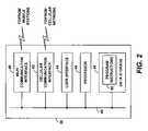
- FIG. 2is next a simplified block diagram showing various functional components that a multi-mode device such as either of mobile stations 20 and 22 may include in accordance with the present disclosure.
- a multi-mode device 38includes a Wi-Fi communication interface 40 , a cellular communication interface 42 , a user interface 44 , a processor 46 , and data storage 48 , all of which are coupled together by a system bus or other mechanism 49 .
- the components of multi-mode device 38are shown within one unitary box, it should be understood that the components can instead be distributed among various physically separate entities.
- Wi-Fi communication interface 40may comprise an 802.11 chipset and antennas adapted to facilitate Wi-Fi air interface communication with other mobile stations.
- Wi-Fi communication interface 40may also include a Wi-Fi based chipset that allows a mobile station to serve as a Wi-Fi access point, for example, in the same manner that portable wireless devices today can be set to function as Wi-Fi access points.
- Cellular communication interface 42may comprise a cellular chipset and antennas adapted to facilitate communication with a cellular radio access network according to a protocol such as CDMA, TDMA, AMPS, or GSM, for instance.
- Wi-Fi communication interface 40 and cellular communication interface 42can be integrated in whole or in part, such as in the form of an integrated chipset and/or sharing one or more antennas.
- User interface 44preferably comprises user output components such as a display screen and audio speaker, and input components such as a keypad, touch-sensitive screen, and microphone. Further, user interface 44 preferably includes circuitry for converting between analog and digital representations of voice or media, so as to facilitate communication of such media.
- Processor 46preferably comprises one or more general purpose processors and/or special purpose processors.
- data storage 48preferably includes one or more volatile and/or non-volatile storage components (e.g., magnetic, optical, or organic components) and may be integrated in whole or in part with processor 46 .
- data storage 48contains program instructions executable by processor 46 to carry out various functions described herein, whether as mobile station 20 or mobile station 22 .
- the program instructionsmay be executable by the processor to receive/detect from RAN 12 a page request carrying a bridge-indicator and to responsively turn on a bridge function.
- the program instructionsmay be executable by the processor to function as a Wi-Fi access point, by broadcasting an SSID via Wi-Fi interfaced 40 , receiving/detecting an association request from a Wi-Fi station, authenticating and otherwise establishing a Wi-Fi station with the Wi-Fi station, and acting as a DHCP server to assign local IP addresses to Wi-Fi stations that associate with it.
- the program instructionsmay be executable by the processor to function as a Wi-Fi station, by detecting an SSID broadcast from an access point, sending an association request to the access point and establishing Wi-Fi association with the access point, and sending a DHCP request to receive an IP address assignment from the access point.
- program instructionsmay define SIP client logic for engaging in IP-based call setup signaling, such as SIP signaling, and the program instructions may define RTP client logic for facilitating RTP communication in a manner well known in the art.
- the functions described herein as being carried out by the RANcan be carried out by any RAN element or by a combination of RAN elements.
- BTS 14 , BSC 24 , and/or MSC 26may operate to (i) receive a call setup request seeking to setup a communication to mobile station 22 , (ii) page mobile station 22 , (iii) encounter a call setup failure, (iv) responsively select and page mobile station 20 instead, providing mobile station 20 with a bridge-indicator that causes mobile station 20 to function as a bridge, and then (v) communicate with mobile station 22 via mobile station 20 .
- the element or elements of RAN 12 that carry out these functionsmay be arranged in a conventional manner but may further include stored program logic executable by a processor to carry out the various RAN functions described herein.
- the RANwill include or have access to profile data for each mobile station that it serves, i.e., each mobile station in its coverage area 16 .
- the profile data for each mobile stationcan be conventionally maintained at a visitor location register (VLR) in the RAN, downloaded from the mobile station's home location register (HLR) when the mobile station enters coverage of the RAN.
- VLRvisitor location register
- HLRhome location register
- the profile data for each mobile stationmay include typical service profile parameters but may further include data that identifies one or more bridge nodes that can be used when setting up calls to the mobile station.
- a bridge nodemay be another mobile station, which the service profile may identify by its MIN or in some other manner, to facilitate call setup to the bridge node.
- a cellular service providermay offer the present wireless bridging service as an enhanced service for its subscribers, or particularly to subscribers who have dual mode mobile stations arranged to function in the manner presently described.
- a subscribermay benefit from the bridging function in return for the subscriber agreeing to allow his or her mobile station to function as a bridge to benefit other subscribers.
- the service providermay charge a fee for providing the bridging service to its subscribers, or the service provider may credit subscribers in return for their agreement to have their mobile stations function as bridge nodes.
- a cellular service providermay allow a subscriber to designate (or request) one or more particular mobile stations to function as bridge nodes for the subscriber's mobile station.
- the service providermay host a provisioning website, IVR, or operator center through which the subscriber can specify the MINs of desired bridge nodes.
- the service providermay then record the designated MIN(s) in the subscriber's service profile and update or load the profile onto the subscriber's HLR for downloading in turn to the VLR of RAN 12 .
- the RAN 12may then consult the mobile station's service profile and try to read the listed bridge node(s) in order of priority listed in the profile. Alternatively or additionally, when seeking to set up a bridged call to a mobile station, RAN 12 may search the VLR records for all mobile stations currently in its coverage and may select one such mobile station whose VLR record indicates that it is able to function as a bridge node.
- the inventive processmay begin when RAN 12 receives a call setup request, seeking to set up a call to mobile station 22 .
- the call setup requestcould be a request from mobile station 18 (e.g., a request to call another mobile station 22 served by the same RAN), or it could be a request that arrives via a transport network such as the PSTN 30 or the packet-switched network 34 .
- a call setup request from the PSTN 30may arrive at MSC 26 in the form of an ISUP IAM message in a manner well known in the art.
- a call setup request from the packet-switched networkmay arrive at PDSN 28 in the form of a packet-based call setup request message such as a SIP INVITE for instance, destined to the IP address of mobile station 22 .
- a packet-based call setup request messagesuch as a SIP INVITE for instance, destined to the IP address of mobile station 22 .
- Other sorts of call requestsare possible as well.
- the RAN 12When the RAN 12 receives the call setup request, it may attempt to page mobile station 22 by transmitting a general page message destined to the mobile station 22 . If mobile station 22 is within coverage area 16 of RAN 12 , it may successfully receive the page and engage in further signaling with RAN 12 to set up a radio link for the call, and the mobile station 22 may then engage in bearer communication via the radio link and the RAN. However, if the page fails or if the call setup effort otherwise fails for any reason, RAN 12 will then attempt a bridged call setup.
- RAN 12may (i) select a bridge node such as mobile station 20 , (ii) establish a first wireless link with the bridge node, and cause the bridge node to establish a second wireless link with the mobile station 22 , and (iii) engage in, or facilitate, call setup signaling with mobile station 22 via the bridge node.
- a bridge nodesuch as mobile station 20
- RAN 12may (i) select a bridge node such as mobile station 20 , (ii) establish a first wireless link with the bridge node, and cause the bridge node to establish a second wireless link with the mobile station 22 , and (iii) engage in, or facilitate, call setup signaling with mobile station 22 via the bridge node.
- RAN 12may consult its VLR to determine whether a bridge node is specified for use in the profile of mobile station 22 . If so, the RAN may attempt to use that specified bridge node. Alternatively, the RAN may consult the VLR to determine whether any other mobile station is designated as one able to function as a bridge node. Optimally, the RAN would select a bridge node that is not currently engaged in a call.
- the RAN 12may apply various other criteria when selecting a bridge node to use. For instance, because a particular Wi-Fi link may have a limited range, the RAN may seek to select a bridge node that is within close range of the mobile station 22 that the RAN is trying to contact. The RAN may do so by consulting its records to determine which bridge node (or perhaps multiple specified by the VLR) is served by the same BTS, or perhaps in the same BTS sector, as mobile station 22 . Alternatively, well known, more advanced location technology could be used to track the location of each potential bridge node and the last known location of the mobile station 22 at issue, and the RAN could select a bridge node closest to the last known location of the mobile station.
- the RANwill then establish a cellular wireless link with the bridge node, if the cellular wireless link does not already exist. Assuming that the RAN selects mobile station 20 as the bridge node, the RAN may establish a cellular wireless link with mobile station 20 in the same manner that the RAN would normally establish a cellular wireless link with any mobile station, except that the RAN would additionally provide the presently contemplated bridge-indicator to the mobile station 20 .
- the RANmay transmit to mobile station 20 a general page message seeking to set up a radio link with the mobile station 20 .
- the RANmay include in the page message a bridge-indicator, such as a newly defined service option code, for instance, which mobile station 20 would programmatically detect as a directive for mobile station 20 to begin functioning as a bridge node if it is not functioning as one already.
- a bridge-indicatorsuch as a newly defined service option code, for instance, which mobile station 20 would programmatically detect as a directive for mobile station 20 to begin functioning as a bridge node if it is not functioning as one already.
- a given mobile stationcan function as a bridge node for more than one other mobile station at a time.
- the RANcan simply use it as a basis to extend a communication to another mobile station.
- a radio linkmay be established. Further, in response to the bridge-indicator, mobile station 20 may turn on its Wi-Fi access point functionality and begin broadcasting a predefined SSID for detection by mobile station 22 .
- mobile station 22will have also detected a lack of signal from RAN 12 and will responsively have turned on its own Wi-Fi station functionality and begun scanning for the predefined SSID.
- mobile station 20would optimally detect the SSID broadcast by mobile station 20 and, upon detecting the SSID, may engage in typical Wi-Fi association with mobile station 20 .
- mobile stationalternatively already has an IP address assigned by the cellular wireless system (e.g. by a mobile-IP home agent), the mobile station need not acquire a new IP address from mobile station 22 .
- call setup messagescan then pass between RAN 12 and mobile station 22 via mobile station 20 , so as to set up a call with mobile station 22 . Further, after setup of the call, the RAN 12 may maintain a call session with mobile station 22 via mobile station 20 .
- FIG. 3is a call flow diagram illustrating an example of how the invention may work in practice to extend a call to mobile station 22 via mobile station 20 .
- This exampleassumes that mobile station 22 is in a dormant state and thus has an IP address but no radio link.
- the examplefurther assumes that an originating endpoint has transmitted a call setup request in the form of a SIP INVITE, which RAN 12 receives as packet data destined to the IP address of mobile station 22 .
- RAN 12thus receives the SIP INVITE destined to the IP address of mobile station 22 . Because mobile station 22 is dormant, RAN 12 then pages the mobile station 22 , at step 72 , in an effort to set up a radio link through which to transmit the INVITE message to the mobile station 22 . Although only one page message is shown at step 72 , the RAN could try paging the mobile station 22 twice or any specified number of times before concluding, as shown at point 74 , that the page has failed or more generally that call setup effort has failed. This failure may occur because mobile station 22 is out of coverage or for any of a variety of other reasons.
- RAN 12may then programmatically select mobile station 20 to use as a bridge node for extending the call to mobile station 22 .
- RAN 12then pages the selected mobile station 20 in an effort to establish a cellular radio link with mobile station 20 .
- RAN 12includes in the page message to mobile station 20 a bridge-indicator, such as a special service option code, which directs mobile station 20 to begin functioning as a bridge node if mobile station 20 is not functioning in that manner already.
- mobile station 20replies to RAN 12 with a page response, and the RAN and mobile station 20 engage in any further signaling necessary to establish a bearer channel between the RAN and mobile station 20 .
- a cellular radio link 80is thereby established between RAN 12 and mobile station 20 .
- mobile station 20begins functioning as a Wi-Fi access point to facilitate establishing a Wi-Fi link with mobile station 22 .
- mobile station 20broadcasts the predefined SSID.
- Mobile station 22detects that SSID and, at step 84 , mobile station 22 engages in an association process with mobile station 20 .
- a Wi-Fi link 86is established between mobile station 20 and mobile station 22 .
- RAN 12sends the SIP INVITE over that link to mobile station 20 , at step 88 .
- mobile station 20in response to establishment of the Wi-Fi link with mobile station 22 , sends the SIP INVITE over the Wi-Fi link (perhaps generally broadcasting it on the link, for receipt by the mobile station having the destination IP address, namely, mobile station 22 ), at step 90 .
- typical SIP signalingmay then proceed between mobile station 22 and the originating endpoint, via mobile station 20 as a bridge.
- mobile station 22may accept the session invitation by sending a SIP 200 OK message via Wi-Fi link 86 to mobile station 20 , at step 92 , which mobile station 20 then forwards by rote over cellular link 80 to RAN 12 , at step 94 .
- RAN 12then forwards the SIP 200 OK message over packet network 34 to the originating endpoint, at step 94 .
- a SIP ACK messagethen passes from the originating endpoint to RAN 12 (at step 98 ), from RAN 12 via cellular link 80 to mobile station 20 (at step 100 ), and from mobile station 20 via Wi-Fi link 86 to mobile station 22 (at step 102 ), thereby concluding the session setup.
- the sessionmay then proceed, at step 104 , between the originating endpoint and mobile station 22 , via RAN 12 and mobile station 20 as a bridge node.
- bridging a cellular wireless link to a WLAN linkincluding CDMA packet-data link for the cellular link and 802.11 for the WLAN link
- the inventioncan be extended to include bridging a variety of wireless networks.
- bridging devicesmay be used. Such devices include cell phones, wireless handheld devices, laptops, etc.
- callgenerally refers to any sort of communication session.
Landscapes
- Engineering & Computer Science (AREA)
- Computer Networks & Wireless Communication (AREA)
- Signal Processing (AREA)
- Mobile Radio Communication Systems (AREA)
Abstract
Description
Claims (19)
Priority Applications (2)
| Application Number | Priority Date | Filing Date | Title |
|---|---|---|---|
| US11/393,058US7720021B1 (en) | 2006-03-30 | 2006-03-30 | Method and system for setting up a call to a mobile station via another mobile station |
| US11/455,602US9036510B1 (en) | 2006-03-30 | 2006-06-19 | Method and system for setting up a conference with a mobile station via another mobile station |
Applications Claiming Priority (1)
| Application Number | Priority Date | Filing Date | Title |
|---|---|---|---|
| US11/393,058US7720021B1 (en) | 2006-03-30 | 2006-03-30 | Method and system for setting up a call to a mobile station via another mobile station |
Related Child Applications (1)
| Application Number | Title | Priority Date | Filing Date |
|---|---|---|---|
| US11/455,602Continuation-In-PartUS9036510B1 (en) | 2006-03-30 | 2006-06-19 | Method and system for setting up a conference with a mobile station via another mobile station |
Publications (1)
| Publication Number | Publication Date |
|---|---|
| US7720021B1true US7720021B1 (en) | 2010-05-18 |
Family
ID=42166647
Family Applications (1)
| Application Number | Title | Priority Date | Filing Date |
|---|---|---|---|
| US11/393,058Active2029-01-09US7720021B1 (en) | 2006-03-30 | 2006-03-30 | Method and system for setting up a call to a mobile station via another mobile station |
Country Status (1)
| Country | Link |
|---|---|
| US (1) | US7720021B1 (en) |
Cited By (25)
| Publication number | Priority date | Publication date | Assignee | Title |
|---|---|---|---|---|
| US20090029691A1 (en)* | 2007-07-25 | 2009-01-29 | Microsoft Corporation | Base station initiated proximity service discovery and connection establishment |
| US20090029728A1 (en)* | 2007-07-25 | 2009-01-29 | Microsoft Corporation | Base station initiated proximity service discovery and connection establishment |
| US20090185527A1 (en)* | 2006-05-24 | 2009-07-23 | Haseeb Akhtar | Radio Resource Reservation for Wireless Networks |
| US20100130240A1 (en)* | 2008-11-24 | 2010-05-27 | Plantronics, Inc. | Portable Network Device For The Discovery Of Nearby Devices And Services |
| US20110158143A1 (en)* | 2009-12-29 | 2011-06-30 | Jeong Kyun Yun | Mobile terminal and controlling method thereof |
| US20110310863A1 (en)* | 2010-06-22 | 2011-12-22 | Hugh Shieh | Arrangement for controlling access to data network |
| US8213396B1 (en)* | 2009-07-15 | 2012-07-03 | Sprint Spectrum L.P. | Methods and systems for disabling paging to a wireless communication device |
| US20120224567A1 (en)* | 2011-03-03 | 2012-09-06 | Hon Hai Precision Industry Co., Ltd. | Mobile phone and method for receiving calls |
| CN102739480A (en)* | 2011-03-29 | 2012-10-17 | 索尼公司 | Management device, management method, communication device, communication method, relay device and relay method |
| US8472969B1 (en) | 2011-06-21 | 2013-06-25 | Sprint Spectrum L.P. | Method and system for selecting a coverage area in which a mobile station should operate |
| US20130171937A1 (en)* | 2010-04-30 | 2013-07-04 | Nokia Corporation | Method and apparatus for providing mobile services outside of cellular coverage |
| US20130201935A1 (en)* | 2012-02-03 | 2013-08-08 | Qualcomm Incorporated | Apparatus and method of channel setup |
| WO2014074395A1 (en)* | 2012-11-08 | 2014-05-15 | Apple Inc. | Extending use of a cellular communication capabilities in a wireless device to another device |
| US20140248870A1 (en)* | 2008-06-13 | 2014-09-04 | Qualcomm Incorporated | Mobile devices with femto cell functionality |
| US20140334306A1 (en)* | 2011-12-28 | 2014-11-13 | Huawei Technologies Co., Ltd. | Data transmission method and apparatus |
| US20150110100A1 (en)* | 2010-03-09 | 2015-04-23 | Seiko Epson Corporation | Wireless communication system, wireless communication device, projector, and wireless communication method |
| US20150138987A1 (en)* | 2013-11-20 | 2015-05-21 | At & T Mobility Ii Llc | Method and system for efficient management of a communication system |
| US20150138963A1 (en)* | 2013-11-20 | 2015-05-21 | At & T Mobility Ii Llc | Method and system for managing wireless access to a communication system |
| WO2015085950A1 (en) | 2013-12-13 | 2015-06-18 | Huawei Technologies Co., Ltd. | Software-defined network infrastructure having virtual range extenders |
| US9306681B2 (en) | 2011-01-13 | 2016-04-05 | Eric James Malinen | System and method of on-body mobile devices to reduce radiation exposure to the upper body |
| US9351278B1 (en) | 2014-01-21 | 2016-05-24 | Sprint Spectrum L.P. | Controlling wireless paging parameters based on device type prevalence |
| US9363741B1 (en)* | 2013-12-20 | 2016-06-07 | Sprint Spectrum L.P. | Managing inter-network set up of wireless communication service |
| US9730108B2 (en) | 2012-12-14 | 2017-08-08 | Plantronics, Inc. | Network architecture using Wi-Fi devices |
| US9763141B1 (en) | 2014-01-21 | 2017-09-12 | Sprint Spectrum L.P. | Controlling handoff and channel assignment parameters based on device type |
| EP2408234B1 (en)* | 2010-07-15 | 2019-02-27 | Nokia Technologies Oy | Method and apparatus for device initiated offloading to unlicensed bands |
Citations (23)
| Publication number | Priority date | Publication date | Assignee | Title |
|---|---|---|---|---|
| US5737703A (en) | 1994-12-23 | 1998-04-07 | Nokia Mobile Phones Limited | Multi-mode radio telephone which executes handover between different system |
| US5774461A (en) | 1995-09-27 | 1998-06-30 | Lucent Technologies Inc. | Medium access control and air interface subsystem for an indoor wireless ATM network |
| US5898679A (en)* | 1996-12-30 | 1999-04-27 | Lucent Technologies Inc. | Wireless relay with selective message repeat and method of operation thereof |
| US5907540A (en)* | 1994-09-21 | 1999-05-25 | Hitachi, Ltd. | Radio data communication apparatus having a relay function and radio data communication method and system using the same |
| US6115762A (en) | 1997-03-07 | 2000-09-05 | Advanced Micro Devices, Inc. | PC wireless communications utilizing an embedded antenna comprising a plurality of radiating and receiving elements responsive to steering circuitry to form a direct antenna beam |
| US6205495B1 (en) | 1998-07-15 | 2001-03-20 | Gateway, Inc. | Wireless interface for standard modems |
| US6292747B1 (en) | 2000-04-20 | 2001-09-18 | International Business Machines Corporation | Heterogeneous wireless network for traveler information |
| US20010036830A1 (en) | 2000-04-17 | 2001-11-01 | Geng Wu | Network resource sharing during handover of a mobile station between cellular wireless networks |
| US6327254B1 (en) | 1997-10-14 | 2001-12-04 | Lucent Technologies Inc. | Method for bandwidth sharing in a multiple access system for communications networks |
| US6330244B1 (en) | 1996-09-05 | 2001-12-11 | Jerome Swartz | System for digital radio communication between a wireless lan and a PBX |
| US6438117B1 (en) | 2000-01-07 | 2002-08-20 | Qualcomm Incorporated | Base station synchronization for handover in a hybrid GSM/CDMA network |
| US20030091021A1 (en) | 2001-11-13 | 2003-05-15 | Nokia Corporation | Physically scoped multicast in multi-access networks |
| US6680923B1 (en) | 2000-05-23 | 2004-01-20 | Calypso Wireless, Inc. | Communication system and method |
| US20040185845A1 (en)* | 2003-02-28 | 2004-09-23 | Microsoft Corporation | Access point to access point range extension |
| US20040236850A1 (en)* | 2003-05-19 | 2004-11-25 | Microsoft Corporation, Redmond, Washington | Client proximity detection method and system |
| US20040264410A1 (en) | 2003-06-30 | 2004-12-30 | Motorola, Inc. | Method and apparatus for providing a communication unit with a handoff between networks |
| US20050085257A1 (en) | 2003-10-01 | 2005-04-21 | Laird Mark D. | Mobile emergency notification system |
| US20060056440A1 (en) | 2004-09-16 | 2006-03-16 | Nokia Corporation | Managing conference communication in a communication system |
| US7193987B2 (en)* | 2000-03-18 | 2007-03-20 | Telefonaktiebolaget Lm Ericsson (Publ) | IP communication in a cellular telecommunications system |
| US20070091830A1 (en) | 2005-09-30 | 2007-04-26 | Coulas Michael F | Method and apparatus for making sidebar calls |
| US20070111743A1 (en) | 2005-11-14 | 2007-05-17 | Leigh Randolph J | Mobile-Device Directed Conference Call Interface |
| US7408948B2 (en)* | 2001-04-17 | 2008-08-05 | Nokia Corporation | Packet mode speech communication |
| US20090054070A1 (en)* | 2002-10-18 | 2009-02-26 | Gallagher Michael D | Apparatus and Method for Extending the Coverage Area of a Licensed Wireless Communication System Using an Unlicensed Wireless Communication System |
- 2006
- 2006-03-30USUS11/393,058patent/US7720021B1/enactiveActive
Patent Citations (23)
| Publication number | Priority date | Publication date | Assignee | Title |
|---|---|---|---|---|
| US5907540A (en)* | 1994-09-21 | 1999-05-25 | Hitachi, Ltd. | Radio data communication apparatus having a relay function and radio data communication method and system using the same |
| US5737703A (en) | 1994-12-23 | 1998-04-07 | Nokia Mobile Phones Limited | Multi-mode radio telephone which executes handover between different system |
| US5774461A (en) | 1995-09-27 | 1998-06-30 | Lucent Technologies Inc. | Medium access control and air interface subsystem for an indoor wireless ATM network |
| US6330244B1 (en) | 1996-09-05 | 2001-12-11 | Jerome Swartz | System for digital radio communication between a wireless lan and a PBX |
| US5898679A (en)* | 1996-12-30 | 1999-04-27 | Lucent Technologies Inc. | Wireless relay with selective message repeat and method of operation thereof |
| US6115762A (en) | 1997-03-07 | 2000-09-05 | Advanced Micro Devices, Inc. | PC wireless communications utilizing an embedded antenna comprising a plurality of radiating and receiving elements responsive to steering circuitry to form a direct antenna beam |
| US6327254B1 (en) | 1997-10-14 | 2001-12-04 | Lucent Technologies Inc. | Method for bandwidth sharing in a multiple access system for communications networks |
| US6205495B1 (en) | 1998-07-15 | 2001-03-20 | Gateway, Inc. | Wireless interface for standard modems |
| US6438117B1 (en) | 2000-01-07 | 2002-08-20 | Qualcomm Incorporated | Base station synchronization for handover in a hybrid GSM/CDMA network |
| US7193987B2 (en)* | 2000-03-18 | 2007-03-20 | Telefonaktiebolaget Lm Ericsson (Publ) | IP communication in a cellular telecommunications system |
| US20010036830A1 (en) | 2000-04-17 | 2001-11-01 | Geng Wu | Network resource sharing during handover of a mobile station between cellular wireless networks |
| US6292747B1 (en) | 2000-04-20 | 2001-09-18 | International Business Machines Corporation | Heterogeneous wireless network for traveler information |
| US6680923B1 (en) | 2000-05-23 | 2004-01-20 | Calypso Wireless, Inc. | Communication system and method |
| US7408948B2 (en)* | 2001-04-17 | 2008-08-05 | Nokia Corporation | Packet mode speech communication |
| US20030091021A1 (en) | 2001-11-13 | 2003-05-15 | Nokia Corporation | Physically scoped multicast in multi-access networks |
| US20090054070A1 (en)* | 2002-10-18 | 2009-02-26 | Gallagher Michael D | Apparatus and Method for Extending the Coverage Area of a Licensed Wireless Communication System Using an Unlicensed Wireless Communication System |
| US20040185845A1 (en)* | 2003-02-28 | 2004-09-23 | Microsoft Corporation | Access point to access point range extension |
| US20040236850A1 (en)* | 2003-05-19 | 2004-11-25 | Microsoft Corporation, Redmond, Washington | Client proximity detection method and system |
| US20040264410A1 (en) | 2003-06-30 | 2004-12-30 | Motorola, Inc. | Method and apparatus for providing a communication unit with a handoff between networks |
| US20050085257A1 (en) | 2003-10-01 | 2005-04-21 | Laird Mark D. | Mobile emergency notification system |
| US20060056440A1 (en) | 2004-09-16 | 2006-03-16 | Nokia Corporation | Managing conference communication in a communication system |
| US20070091830A1 (en) | 2005-09-30 | 2007-04-26 | Coulas Michael F | Method and apparatus for making sidebar calls |
| US20070111743A1 (en) | 2005-11-14 | 2007-05-17 | Leigh Randolph J | Mobile-Device Directed Conference Call Interface |
Non-Patent Citations (15)
| Title |
|---|
| "802.11b and 3G Synergies for 2002," 802.11 Insights, http://www.80211-planet.com/columns/article/0,4000,1781-950811,00.html, printed Feb. 22, 2002. |
| "E-200 Cassiopeia Pocket PC 2002," Casio, http://www.casio.com/personalpcs/product.cfm?section=19&product=4146, printed Feb. 22, 2002. |
| "Making Notebooks Truly Mobile," T Techtv, http://www.techtv.com/freshgear/products/story/0,23008,3347281,00.html., printed Feb. 25, 2002. |
| "Product Description," WeRoam, http://www.weroam.com/, printed Feb. 25, 2002. |
| "Roaming Between WLAN and GSM Networks to Become Easier," thinkmobile, http://www.thinkmobile.com/laptops/news/00/48/33/, printed Feb. 25, 2002. |
| Internet Engineering Task Force ("IETF") Request for Comments ("RFCs") 2002, "IP Mobility Support," C. Perkins, Oct. 1996. |
| Internet Engineering Task Force ("IETF") Request for Comments ("RFCs") 2003, "IP Encapsulation within IP," C. Perkins, Oct. 1996. |
| Internet Engineering Task Force ("IETF") Request for Comments ("RFCs") 2004, "Minimal Encapsulation within IP," C. Perkins, Oct. 1996. |
| Internet Engineering Task Force ("IETF") Request for Comments ("RFCs") 2005, "Applicability Statement for IP Mobility Support," J. Solomom, Oct. 1996. |
| Internet Engineering Task Force ("IETF") Request for Comments ("RFCs") 768, "User Datagram Protocol," J. Postel, Aug. 1980. |
| Internet Engineering Task Force ("IETF") Request for Comments ("RFCs") 791, "Internet Protocol DARPA Internet Program Protocol Specification," Information Sciences Institute, Sep. 1981. |
| Internet Engineering Task Force ("IETF") Request for Comments ("RFCs") 793, "Transmission Control Protocol DARPA Internet Program Protocol Specification," Information Sciences Institute, Sep. 1981. |
| Office Action from U.S. Appl. No. 11/455,602, dated Aug. 18, 2009. |
| U.S. Appl. No. 10/200,263, filed Jul. 22, 2002 entitled "Wireless Bridge For Interfacing An 802.11 Network With A Cellular Network." |
| U.S. Appl. No. 11/455,602, filed Jun. 19, 2006 entitled "Method And System For Setting Up A Conference With A Mobile Station Via Another Mobile Station." |
Cited By (60)
| Publication number | Priority date | Publication date | Assignee | Title |
|---|---|---|---|---|
| US20090185527A1 (en)* | 2006-05-24 | 2009-07-23 | Haseeb Akhtar | Radio Resource Reservation for Wireless Networks |
| US8825070B2 (en)* | 2006-05-24 | 2014-09-02 | Apple Inc. | Radio resource reservation for wireless networks |
| US8681691B2 (en)* | 2007-07-25 | 2014-03-25 | Microsoft Corporation | Base station initiated proximity service discovery and connection establishment |
| US20090029691A1 (en)* | 2007-07-25 | 2009-01-29 | Microsoft Corporation | Base station initiated proximity service discovery and connection establishment |
| US20090029728A1 (en)* | 2007-07-25 | 2009-01-29 | Microsoft Corporation | Base station initiated proximity service discovery and connection establishment |
| US7974574B2 (en) | 2007-07-25 | 2011-07-05 | Microsoft Corporation | Base station initiated proximity service discovery and connection establishment |
| US10321515B2 (en) | 2007-07-25 | 2019-06-11 | Microsoft Technology Licensing, Llc | Base station initiated proximity service discovery and connection establishment |
| US9036558B2 (en) | 2007-07-25 | 2015-05-19 | Microsoft Technology Licensing, Llc | Base station initiated proximity service discovery and connection establishment |
| US20140248870A1 (en)* | 2008-06-13 | 2014-09-04 | Qualcomm Incorporated | Mobile devices with femto cell functionality |
| US9924436B2 (en)* | 2008-06-13 | 2018-03-20 | Qualcomm Incorporated | Mobile devices with femto cell functionality |
| US20100130240A1 (en)* | 2008-11-24 | 2010-05-27 | Plantronics, Inc. | Portable Network Device For The Discovery Of Nearby Devices And Services |
| US9014736B2 (en)* | 2008-11-24 | 2015-04-21 | Plantronics, Inc. | Portable network device for the discovery of nearby devices and services |
| US8213396B1 (en)* | 2009-07-15 | 2012-07-03 | Sprint Spectrum L.P. | Methods and systems for disabling paging to a wireless communication device |
| US9167526B2 (en)* | 2009-12-29 | 2015-10-20 | Lg Electronics Inc. | Mobile terminal and controlling method thereof |
| US20110158143A1 (en)* | 2009-12-29 | 2011-06-30 | Jeong Kyun Yun | Mobile terminal and controlling method thereof |
| US20150110100A1 (en)* | 2010-03-09 | 2015-04-23 | Seiko Epson Corporation | Wireless communication system, wireless communication device, projector, and wireless communication method |
| US9769595B2 (en) | 2010-04-30 | 2017-09-19 | Nokia Technologies Oy | Method and apparatus for providing mobile services outside of cellular coverage |
| US20130171937A1 (en)* | 2010-04-30 | 2013-07-04 | Nokia Corporation | Method and apparatus for providing mobile services outside of cellular coverage |
| US9125005B2 (en)* | 2010-04-30 | 2015-09-01 | Nokia Technologies Oy | Method and apparatus for providing mobile services outside of cellular coverage |
| US20110310863A1 (en)* | 2010-06-22 | 2011-12-22 | Hugh Shieh | Arrangement for controlling access to data network |
| US8917735B2 (en)* | 2010-06-22 | 2014-12-23 | At&T Mobility Ii Llc | Arrangement for controlling access to data network |
| EP2408234B1 (en)* | 2010-07-15 | 2019-02-27 | Nokia Technologies Oy | Method and apparatus for device initiated offloading to unlicensed bands |
| US9306681B2 (en) | 2011-01-13 | 2016-04-05 | Eric James Malinen | System and method of on-body mobile devices to reduce radiation exposure to the upper body |
| US20120224567A1 (en)* | 2011-03-03 | 2012-09-06 | Hon Hai Precision Industry Co., Ltd. | Mobile phone and method for receiving calls |
| US8457030B2 (en)* | 2011-03-03 | 2013-06-04 | Hon Hai Precision Industry Co., Ltd. | Mobile phone and method for receiving calls |
| US9002369B2 (en) | 2011-03-29 | 2015-04-07 | Sony Corporation | Management device, management method, communication device, communication method, relay device, relay method, program, and communication system |
| EP2506636A3 (en)* | 2011-03-29 | 2012-12-26 | Sony Corporation | Management device, management method, communication device, communication method, relay device and relay method for a WLAN comprising having relaying functionality |
| CN102739480A (en)* | 2011-03-29 | 2012-10-17 | 索尼公司 | Management device, management method, communication device, communication method, relay device and relay method |
| CN102739480B (en)* | 2011-03-29 | 2017-09-22 | 索尼公司 | Managing device and method, communicator and method and relay and method |
| US8855662B1 (en) | 2011-06-21 | 2014-10-07 | Sprint Spectrum L.P. | Method and system for selecting a coverage area in which a mobile station should operate |
| US8472969B1 (en) | 2011-06-21 | 2013-06-25 | Sprint Spectrum L.P. | Method and system for selecting a coverage area in which a mobile station should operate |
| EP2790434A4 (en)* | 2011-12-28 | 2015-03-25 | Huawei Tech Co Ltd | METHOD AND APPARATUS FOR TRANSMITTING DATA |
| US20140334306A1 (en)* | 2011-12-28 | 2014-11-13 | Huawei Technologies Co., Ltd. | Data transmission method and apparatus |
| US10075869B2 (en)* | 2011-12-28 | 2018-09-11 | Huawei Technologies Co., Ltd. | Data transmission method and apparatus |
| US20130201935A1 (en)* | 2012-02-03 | 2013-08-08 | Qualcomm Incorporated | Apparatus and method of channel setup |
| US9844087B2 (en) | 2012-11-08 | 2017-12-12 | Apple Inc. | Extending use of a cellular communication capabilities in a wireless device to another device |
| CN108668041A (en)* | 2012-11-08 | 2018-10-16 | 苹果公司 | Wireless user equipment device and method for wireless user equipment device |
| US12245301B2 (en) | 2012-11-08 | 2025-03-04 | Apple Inc. | Extending use of a cellular communication capabilities in a wireless device to another device |
| US9615392B2 (en) | 2012-11-08 | 2017-04-04 | Apple Inc. | Extending use of a cellular communication capabilities in a wireless device to another device |
| DE112013007776B4 (en) | 2012-11-08 | 2023-12-21 | Apple Inc. | Extending the use of a mobile communications capability in a wireless device to another device |
| US11368992B2 (en) | 2012-11-08 | 2022-06-21 | Apple Inc. | Extending use of a cellular communication capabilities in a wireless device to another device |
| US10736160B2 (en) | 2012-11-08 | 2020-08-04 | Apple Inc. | Extending use of a cellular communication capabilities in a wireless device to another device |
| WO2014074395A1 (en)* | 2012-11-08 | 2014-05-15 | Apple Inc. | Extending use of a cellular communication capabilities in a wireless device to another device |
| US10299305B2 (en) | 2012-11-08 | 2019-05-21 | Apple Inc. | Extending use of a cellular communication capabilities in a wireless device to another device |
| US8977269B2 (en) | 2012-11-08 | 2015-03-10 | Apple Inc. | Extending use of a cellular communication capabilities in a wireless device to another device |
| US9730108B2 (en) | 2012-12-14 | 2017-08-08 | Plantronics, Inc. | Network architecture using Wi-Fi devices |
| US10015723B2 (en) | 2013-11-20 | 2018-07-03 | At&T Mobility Ii Llc | Method and system for managing wireless access to a communication system |
| US9781655B2 (en)* | 2013-11-20 | 2017-10-03 | At & T Mobility Ii Llc | Method and system for efficient management of a communication system |
| US9451531B2 (en)* | 2013-11-20 | 2016-09-20 | At&T Mobility Ii Llc | Method and system for managing wireless access to a communication system |
| US20150138987A1 (en)* | 2013-11-20 | 2015-05-21 | At & T Mobility Ii Llc | Method and system for efficient management of a communication system |
| US20150138963A1 (en)* | 2013-11-20 | 2015-05-21 | At & T Mobility Ii Llc | Method and system for managing wireless access to a communication system |
| US10129815B2 (en) | 2013-11-20 | 2018-11-13 | At&T Mobility Ii Llc | Method and system for efficient management of a communication system |
| US10631232B2 (en) | 2013-11-20 | 2020-04-21 | At&T Mobility Ii Llc | Method and system for managing wireless access to a communication system |
| WO2015085950A1 (en) | 2013-12-13 | 2015-06-18 | Huawei Technologies Co., Ltd. | Software-defined network infrastructure having virtual range extenders |
| RU2654128C1 (en)* | 2013-12-13 | 2018-05-16 | Хуавей Текнолоджиз Ко., Лтд. | Software defined network infrastructure with virtual range expanders |
| KR101813649B1 (en) | 2013-12-13 | 2017-12-29 | 후아웨이 테크놀러지 컴퍼니 리미티드 | Software-defined network infrastructure having virtual range extenders |
| EP3069483A4 (en)* | 2013-12-13 | 2016-11-30 | Huawei Tech Co Ltd | NETWORK INFRASTRUCTURE DEFINED BY SOFTWARE HAVING VIRTUAL REACH EXTENSIONS |
| US9363741B1 (en)* | 2013-12-20 | 2016-06-07 | Sprint Spectrum L.P. | Managing inter-network set up of wireless communication service |
| US9351278B1 (en) | 2014-01-21 | 2016-05-24 | Sprint Spectrum L.P. | Controlling wireless paging parameters based on device type prevalence |
| US9763141B1 (en) | 2014-01-21 | 2017-09-12 | Sprint Spectrum L.P. | Controlling handoff and channel assignment parameters based on device type |
Similar Documents
| Publication | Publication Date | Title |
|---|---|---|
| US7720021B1 (en) | Method and system for setting up a call to a mobile station via another mobile station | |
| US7907597B2 (en) | Method and apparatus for providing voice and data services in a mobile communication system with various overlapped access networks | |
| CN201234249Y (en) | Assistant wireless transmission/reception unit and beep-page entity | |
| US8041360B2 (en) | Method of seamless roaming between wireless local area networks and cellular carrier networks | |
| US7769383B2 (en) | Method and system for signaling the state of supplementary services | |
| JP5193030B2 (en) | Multi-mode handset service | |
| EP1782640B1 (en) | Presence detection and handoff for cellular and internet protocol telephony | |
| US8249017B2 (en) | Cellular communication system and method of operation therefor | |
| US8032133B2 (en) | Selecting a network entity | |
| US7526296B1 (en) | Telephone number allocation and management in a wireless access point | |
| US7260072B2 (en) | Data push service system and method using a heterogeneous network | |
| US20120129534A1 (en) | Network initiated context establishment | |
| WO2007043180A1 (en) | Access network selecting method | |
| CN101513090A (en) | Call forwarding between different types of wireless networks | |
| US8837441B2 (en) | Versatile system for WLAN/CDMA2000 interworking | |
| US8165579B2 (en) | Communication system and communication method | |
| US9615294B2 (en) | Dynamic session transfer number for voice call continuity | |
| US8165559B1 (en) | Dynamic access mode determination for emergency service calls | |
| EP1794972B1 (en) | Operating and supporting dual mode user equipment | |
| US8818365B1 (en) | User-invoked re-routing of an incoming call via a stronger serving system | |
| KR20060114810A (en) | Video call area notification service method and system in broadband mobile communication network | |
| KR20050076855A (en) | Method for providing call connection information in mobile communication system |
Legal Events
| Date | Code | Title | Description |
|---|---|---|---|
| AS | Assignment | Owner name:SPRINT SPECTRUM L.P.,KANSAS Free format text:ASSIGNMENT OF ASSIGNORS INTEREST;ASSIGNORS:ZHOU, TONG;MOHAN, DAVID;REEL/FRAME:017742/0112 Effective date:20060327 | |
| STCF | Information on status: patent grant | Free format text:PATENTED CASE | |
| FPAY | Fee payment | Year of fee payment:4 | |
| AS | Assignment | Owner name:DEUTSCHE BANK TRUST COMPANY AMERICAS, NEW YORK Free format text:GRANT OF FIRST PRIORITY AND JUNIOR PRIORITY SECURITY INTEREST IN PATENT RIGHTS;ASSIGNOR:SPRINT SPECTRUM L.P.;REEL/FRAME:041937/0632 Effective date:20170203 | |
| MAFP | Maintenance fee payment | Free format text:PAYMENT OF MAINTENANCE FEE, 8TH YEAR, LARGE ENTITY (ORIGINAL EVENT CODE: M1552) Year of fee payment:8 | |
| AS | Assignment | Owner name:DEUTSCHE BANK TRUST COMPANY AMERICAS, NEW YORK Free format text:SECURITY AGREEMENT;ASSIGNORS:T-MOBILE USA, INC.;ISBV LLC;T-MOBILE CENTRAL LLC;AND OTHERS;REEL/FRAME:053182/0001 Effective date:20200401 | |
| AS | Assignment | Owner name:SPRINT SPECTRUM L.P., KANSAS Free format text:TERMINATION AND RELEASE OF FIRST PRIORITY AND JUNIOR PRIORITY SECURITY INTEREST IN PATENT RIGHTS;ASSIGNOR:DEUTSCHE BANK TRUST COMPANY AMERICAS;REEL/FRAME:052313/0299 Effective date:20200401 | |
| MAFP | Maintenance fee payment | Free format text:PAYMENT OF MAINTENANCE FEE, 12TH YEAR, LARGE ENTITY (ORIGINAL EVENT CODE: M1553); ENTITY STATUS OF PATENT OWNER: LARGE ENTITY Year of fee payment:12 | |
| AS | Assignment | Owner name:SPRINT SPECTRUM LLC, WASHINGTON Free format text:CHANGE OF NAME;ASSIGNOR:SPRINT SPECTRUM L.P.;REEL/FRAME:059044/0022 Effective date:20210325 | |
| AS | Assignment | Owner name:SPRINT SPECTRUM LLC, KANSAS Free format text:RELEASE BY SECURED PARTY;ASSIGNOR:DEUTSCHE BANK TRUST COMPANY AMERICAS;REEL/FRAME:062595/0001 Effective date:20220822 Owner name:SPRINT INTERNATIONAL INCORPORATED, KANSAS Free format text:RELEASE BY SECURED PARTY;ASSIGNOR:DEUTSCHE BANK TRUST COMPANY AMERICAS;REEL/FRAME:062595/0001 Effective date:20220822 Owner name:SPRINT COMMUNICATIONS COMPANY L.P., KANSAS Free format text:RELEASE BY SECURED PARTY;ASSIGNOR:DEUTSCHE BANK TRUST COMPANY AMERICAS;REEL/FRAME:062595/0001 Effective date:20220822 Owner name:SPRINTCOM LLC, KANSAS Free format text:RELEASE BY SECURED PARTY;ASSIGNOR:DEUTSCHE BANK TRUST COMPANY AMERICAS;REEL/FRAME:062595/0001 Effective date:20220822 Owner name:CLEARWIRE IP HOLDINGS LLC, KANSAS Free format text:RELEASE BY SECURED PARTY;ASSIGNOR:DEUTSCHE BANK TRUST COMPANY AMERICAS;REEL/FRAME:062595/0001 Effective date:20220822 Owner name:CLEARWIRE COMMUNICATIONS LLC, KANSAS Free format text:RELEASE BY SECURED PARTY;ASSIGNOR:DEUTSCHE BANK TRUST COMPANY AMERICAS;REEL/FRAME:062595/0001 Effective date:20220822 Owner name:BOOST WORLDWIDE, LLC, KANSAS Free format text:RELEASE BY SECURED PARTY;ASSIGNOR:DEUTSCHE BANK TRUST COMPANY AMERICAS;REEL/FRAME:062595/0001 Effective date:20220822 Owner name:ASSURANCE WIRELESS USA, L.P., KANSAS Free format text:RELEASE BY SECURED PARTY;ASSIGNOR:DEUTSCHE BANK TRUST COMPANY AMERICAS;REEL/FRAME:062595/0001 Effective date:20220822 Owner name:T-MOBILE USA, INC., WASHINGTON Free format text:RELEASE BY SECURED PARTY;ASSIGNOR:DEUTSCHE BANK TRUST COMPANY AMERICAS;REEL/FRAME:062595/0001 Effective date:20220822 Owner name:T-MOBILE CENTRAL LLC, WASHINGTON Free format text:RELEASE BY SECURED PARTY;ASSIGNOR:DEUTSCHE BANK TRUST COMPANY AMERICAS;REEL/FRAME:062595/0001 Effective date:20220822 Owner name:PUSHSPRING, LLC, WASHINGTON Free format text:RELEASE BY SECURED PARTY;ASSIGNOR:DEUTSCHE BANK TRUST COMPANY AMERICAS;REEL/FRAME:062595/0001 Effective date:20220822 Owner name:LAYER3 TV, LLC, WASHINGTON Free format text:RELEASE BY SECURED PARTY;ASSIGNOR:DEUTSCHE BANK TRUST COMPANY AMERICAS;REEL/FRAME:062595/0001 Effective date:20220822 Owner name:IBSV LLC, WASHINGTON Free format text:RELEASE BY SECURED PARTY;ASSIGNOR:DEUTSCHE BANK TRUST COMPANY AMERICAS;REEL/FRAME:062595/0001 Effective date:20220822 |