US7719835B1 - Wiring distribution device for an electronics rack - Google Patents
Wiring distribution device for an electronics rackDownload PDFInfo
- Publication number
- US7719835B1 US7719835B1US12/319,260US31926009AUS7719835B1US 7719835 B1US7719835 B1US 7719835B1US 31926009 AUS31926009 AUS 31926009AUS 7719835 B1US7719835 B1US 7719835B1
- Authority
- US
- United States
- Prior art keywords
- compartment
- housing
- power
- wiring
- cabinet
- Prior art date
- Legal status (The legal status is an assumption and is not a legal conclusion. Google has not performed a legal analysis and makes no representation as to the accuracy of the status listed.)
- Active
Links
- 238000009826distributionMethods0.000titleclaimsabstractdescription59
- 238000001816coolingMethods0.000claimsabstractdescription24
- 239000012080ambient airSubstances0.000claimsabstractdescription4
- 230000003750conditioning effectEffects0.000claimsdescription8
- 239000003570airSubstances0.000claimsdescription3
- 238000012544monitoring processMethods0.000claimsdescription3
- 238000000638solvent extractionMethods0.000claimsdescription2
- 230000000007visual effectEffects0.000claims1
- 238000009434installationMethods0.000description4
- 238000001914filtrationMethods0.000description2
- 239000002184metalSubstances0.000description2
- 238000012986modificationMethods0.000description2
- 230000004048modificationEffects0.000description2
- 230000037361pathwayEffects0.000description2
- 238000010276constructionMethods0.000description1
- 238000009432framingMethods0.000description1
- 238000002955isolationMethods0.000description1
- 239000000463materialSubstances0.000description1
- 230000007935neutral effectEffects0.000description1
- 230000001629suppressionEffects0.000description1
- 238000013022ventingMethods0.000description1
- 238000004804windingMethods0.000description1
Images


Classifications
- H—ELECTRICITY
- H05—ELECTRIC TECHNIQUES NOT OTHERWISE PROVIDED FOR
- H05K—PRINTED CIRCUITS; CASINGS OR CONSTRUCTIONAL DETAILS OF ELECTRIC APPARATUS; MANUFACTURE OF ASSEMBLAGES OF ELECTRICAL COMPONENTS
- H05K7/00—Constructional details common to different types of electric apparatus
- H05K7/20—Modifications to facilitate cooling, ventilating, or heating
- H05K7/20536—Modifications to facilitate cooling, ventilating, or heating for racks or cabinets of standardised dimensions, e.g. electronic racks for aircraft or telecommunication equipment
- H05K7/20554—Forced ventilation of a gaseous coolant
- H05K7/20572—Forced ventilation of a gaseous coolant within cabinets for removing heat from sub-racks, e.g. plenum
- H05K7/20581—Cabinets including a drawer for fans
- H—ELECTRICITY
- H05—ELECTRIC TECHNIQUES NOT OTHERWISE PROVIDED FOR
- H05K—PRINTED CIRCUITS; CASINGS OR CONSTRUCTIONAL DETAILS OF ELECTRIC APPARATUS; MANUFACTURE OF ASSEMBLAGES OF ELECTRICAL COMPONENTS
- H05K7/00—Constructional details common to different types of electric apparatus
- H05K7/14—Mounting supporting structure in casing or on frame or rack
- H05K7/1438—Back panels or connecting means therefor; Terminals; Coding means to avoid wrong insertion
- H05K7/1457—Power distribution arrangements
- H—ELECTRICITY
- H05—ELECTRIC TECHNIQUES NOT OTHERWISE PROVIDED FOR
- H05K—PRINTED CIRCUITS; CASINGS OR CONSTRUCTIONAL DETAILS OF ELECTRIC APPARATUS; MANUFACTURE OF ASSEMBLAGES OF ELECTRICAL COMPONENTS
- H05K7/00—Constructional details common to different types of electric apparatus
- H05K7/20—Modifications to facilitate cooling, ventilating, or heating
- H05K7/20709—Modifications to facilitate cooling, ventilating, or heating for server racks or cabinets; for data centers, e.g. 19-inch computer racks
- H05K7/20718—Forced ventilation of a gaseous coolant
- H05K7/20736—Forced ventilation of a gaseous coolant within cabinets for removing heat from server blades
Definitions
- the present inventionrelates generally to electronics racks, and particularly, to systems for providing power, temperature, and wiring management to components mounted in such racks.
- installation personnelmust connect wiring to the rack or cabinet, as well as the components, in the field, after the electronic components are integrated into the cabinet. The field installation personnel must then work inside the cabinet to interconnect the components.
- the inventionis directed to a wiring distribution device for electronic racks or cabinets.
- the distribution deviceis mounted to the rack or cabinet, and includes modules adapted to provide both internal and external wiring and cable connection and management as required by a particular application.
- the modulesmay include an uninterruptible power supply (UPS), a UPS battery, power distribution (such as circuit breakers), power filtering, power surge and spike protection, power conditioning, entry and routing management for wiring and cables, including electrical or fiber-optic cable, electromagnetic (EM) shield panels, and a cooling module which may be passive or active.
- the cooling modulepreferably includes at least one fan and a temperature sensor, and is adapted to direct airflow through the cabinet to maintain the interior of the cabinet at a desired temperature.
- FIG. 1is a bottom view of an embodiment of the wiring distribution device of the present invention
- FIG. 2is a top view of the wiring distribution device of FIG. 1 ;
- FIG. 3is an isometric view of the distribution device of FIG. 1 ;
- FIG. 4is a side view of the distribution device of FIG. 1 , seen along lines 4 - 4 ;
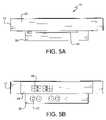
- FIG. 5Ashows a back view of the distribution device of FIG. 1 , seen along lines 5 A- 5 A;
- FIG. 5Bshows a front view of the distribution device of FIG. 1 , seen along lines 5 B- 5 B;
- FIG. 6Ashows an isometric view of the distribution device of FIG. 2 , with the top section of the housing removed;
- FIG. 6Bshows a second isometric view of the distribution device of FIG. 2 , with the top section of the housing removed.
- the distribution devicepreferably includes a high voltage (class 1 wiring) side, a low-voltage (class 2 wiring) side, a cooling device, a power distribution device, and power conditioning device.
- FIGS. 1 and 2are bottom and top views, respectively, of the wiring distribution device 10 , which preferably mounts to the top of a rack or cabinet containing electronic devices (not shown).
- the distribution deviceincludes a housing 12 , which has a bottom 14 , a top 16 , front and rear faces or walls 18 and 20 , respectively, and side walls, 19 , 21 .
- the housing 12preferably includes upper and lower sections, which together define an enclosure with an interior that includes at least two internal chambers or compartments 26 .
- the lower section 24 in the illustrated embodiment of FIGS. 6A and 6Bincludes the bottom 14 , one of either the front or back walls, and one or more flanges 15 extending vertically upward from one or more edges so as to form a tray.
- the upper section 22 in the illustrated embodimentis defined by the top 16 , side walls 19 , 21 and one of the front or rear walls 18 , 20 .
- the upper and lower sectionsare constructed so as to form the housing and define internal compartments when assembled.
- the housingpreferably includes upper an lower sections, as will be apparent to those skilled in the art, the housing could be constructed from individuals components and assembled into a housing with suitable internal compartments.
- the upper and lower sectionscan be formed from any of the various walls or surfaces of the housing.
- the compartmentsare configured to contain support components and provide for wiring and component management.
- the housingmay be constructed of any material suitable for enclosing electrical components or electronic devices, including metal or plastic, and in the illustrated embodiment is preferably made from sheet metal components.
- the distribution devicepreferably includes a surge protection device, which serves to protect one or more user added components that are added to the rack from damage due to surges or spikes in the electric current supplied to the distribution device 10 .
- the surge protection devicepreferably includes at least one, and more preferably more than one, circuit breaker 28 , as seen in FIGS. 3 , 5 B, and 6 A.
- the surge protection deviceis electrically connected to a wiring output point, such as power strip 30 , which preferably includes a plurality of outlets 32 , as seen in FIGS. 1 and 5B .
- the outletsare preferably standard three-prong electrical outlets, but may be of any configuration suitable for connecting a desired electrical device.
- the circuit breakers 28are preferably mounted onto one of the walls of the housing so as to be easily viewable. In the illustrated embodiment, the circuit breakers are shown on the front wall 19 of the distribution device. However, if the device is to be used with a home electronics rack, the circuit breakers 28 may be located on the sides or rear of the housing to obscure view of the breakers. Alternatively, the circuit breakers can be replaced with fuses positioned within a compartment within the housing with an access panel obscuring view of the over-current protection devices.
- the outlets 32 and/or the power strip 30are preferably mounted to the device so as to be accessible from the bottom of the distribution device 10 .
- the distribution deviceis designed for placement on the top of conventional vertical racks, such as EIA standard racks.
- racksgenerally include a top plate that is fastened to the vertical and horizontal frame structure to close off the top.
- the top plate of the rackis removed, thus permitting access to the bottom of the distribution device 10 through the top of the rack.
- the outlets 32are mounted so that they are accessible from the bottom of the distribution device.
- the power strip and/or outletsprotrude downward from the bottom of the housing.
- the power strip and/or outletscould be mounted within the housing with the receptacles accessible from the bottom of the housing.
- the outlets and/or power stripcan be located slightly inward from the edges of the housing so that when the housing 12 is placed on top of the rack, the outlets are not obscured by the rack framing structure.
- the housingincludes multiple internal compartments or chambers 26 .
- the upper and lower sections of the housingare configured so as to create the internal chambers 26 when assembled.
- internal walls 25extend upward from the bottom 14 so as to separate portions of the lower section 23 into compartments or zones.
- some of the compartmentsare preferably accessible by removable covers 34 , and may house any number of support components for performing various functions.
- Some of the compartmentsare preferably also or separately accessible by knock-out plugs 36 formed in the top, bottom and/or sides of the housing. The knock-out plugs may be removed in order to pass wiring W into housing, and may be designed to be either replaceable or permanently removed.
- the bottom section 24 of the housingalso preferably includes at least one opening 38 , which provides access to the inside of the housing and one or more compartments, as seen in FIGS. 1 , 6 A, and 6 B.
- the compartments 26serve various functions.
- the compartmentsmay serve as routing pathways for electronic or fiber-optic cable and wiring, or may house components for power or signal conditioning 50 , power supplies such as a UPS, wiring distributions sections 52 , and/or temperature or thermal control components, such as cooling fans. If any of the support component have the tendency to create electrical interference, the compartments may also include suitable EM shielding.
- the distribution devicemay also include component monitoring and control devices. Additionally, other components, such as lighting modules, may be included.
- the componentsare preferably connected by electromagnetically-shielded channels (not shown), which are preferably segregated to separate class 1 and class 2 cables.
- a power supply and quality module 40is positioned adjacent to an access point, such as a knock out plug or panel, for receiving power from an external supply.
- the power supply module 40preferably is an integrated load center featuring at least one circuit breaker 28 or other automatic safety shutoff device, bond wire termination points, hardwired or pluggable power strips 30 , local receptacles that include reusable strain relief, and a power buss.
- One suitable power strip that can be hard-wiredis the PD SeriesTM power strip sold by Middle Atlantic Products, Inc., Fairfield, N.J.
- the power input side of the devicealso includes a wiring input point (not shown in FIG. 6A , but could be knock-out plugs 36 in FIG.
- the moduleis preferably configured to support various load center configurations, including direct branch circuit feeds, 120/120 with a common isolated neutral line and a split-single configuration, and a 120/120 split-neutral configuration with an isolation transformer feed and two independent secondary windings, or a single 120V feed.
- the power supply modulepreferably includes not only a UPS, but also an additional battery backup for providing limited power supply in the event of loss of the main power.
- a surge suppression deviceis preferably included which protects the cabinet's electrical components (and/or the components in the distribution device, against power surges or spikes.
- the distribution deviceincludes at least one power filtering or conditioning device 50 , such as the ExactPowerTM brand PowerCore a filter power conditioning product (available from Middle Atlantic Products, Inc., Fairfield, N.J.)
- the conditioning deviceis designed to reduce electrical noise on the power lines that are being either sent to or provided from the components in the cabinet.
- the power conditionercan modify an electrical circuit prior to feeding a branch circuit.
- One or more wiring distribution zones or compartments 52are preferably included for providing a way to manage and control the distribution of select wires, such as highly sensitive audio wires that are susceptible to interference.
- the cooling module 42which houses a cooling device, such as a fan 44 , and, preferably, a temperature sensor (not shown) or a passive convection cooling chimney.
- the cooling deviceis preferably located in the middle of the distribution device, and the fan is adapted to force ambient air through the interior of the rack/cabinet on which the device is mounted, in order to maintain an optimum interior temperature.
- the illustrated fanis a single fan having an approximately 10 inch diameter.
- the cooling modulemay include a plurality of smaller fans or other cooling devices that can be mounted to the device at any suitable location, or a passive venting scheme that works by natural convection.
- the devicemay include a temperature display (not shown) that is mounted to the housing and viewable from outside the housing for depicting the temperature in the housing or, more preferably, for depicting the temperature in the rack by means of a remote temperature sensor.
- the monitoring modulepreferably includes at least one display mounted to the housing and visible to a user from outside the housing.
- the displaymay show the temperature inside the rack or cabinet, and may include graphical data or indicator lights depicting the status of the components in the cabinet or in the housing, including voltage, current, and power quality.
- the present inventioncontemplates that the location of the compartments and the components in the compartments, would be selected so as to distance items that are susceptible to interference from items that generate the interference.
- audio wiressuch as line-level or microphone wires
- the present inventionincludes the ability to further protect from electromagnetic interference by dedicated partitioning of the two classes of wires, thus providing further shielding.
- the present inventionincludes a segregated horizontal pathway for wires (power, signal and control) to be run between the bayed racks, without impeding the open space inside the rack as with conventional horizontal runs of wires.
- the wiring from one top distribution deviceis directed to adjacent wire distribution devices, without using internal areas of the rack.
Landscapes
- Engineering & Computer Science (AREA)
- Microelectronics & Electronic Packaging (AREA)
- Physics & Mathematics (AREA)
- Thermal Sciences (AREA)
- Power Engineering (AREA)
- Computer Hardware Design (AREA)
- General Engineering & Computer Science (AREA)
- Aviation & Aerospace Engineering (AREA)
- Cooling Or The Like Of Electrical Apparatus (AREA)
Abstract
Description
The present invention relates generally to electronics racks, and particularly, to systems for providing power, temperature, and wiring management to components mounted in such racks.
It is known to provide a rack or cabinet in which electronic components may be mounted. Existing racks may provide surge suppressors or power strips integrated into the rack; components may be plugged into these strips to make movement of the rack or cabinet more convenient. However, components mounted in such cabinets must still be wired individually to one another and to a power source which is typically located external to the rack or enters the rack from multiple locations.
Also, installation personnel must connect wiring to the rack or cabinet, as well as the components, in the field, after the electronic components are integrated into the cabinet. The field installation personnel must then work inside the cabinet to interconnect the components.
Current wiring systems are not well coordinated or designed for ease of installation and consistency, while also permitting ready access to wired components.
A need, therefore, exists for a wiring distribution device that provides central wire management of components for ease of installation in the field.
The invention is directed to a wiring distribution device for electronic racks or cabinets. The distribution device is mounted to the rack or cabinet, and includes modules adapted to provide both internal and external wiring and cable connection and management as required by a particular application. The modules may include an uninterruptible power supply (UPS), a UPS battery, power distribution (such as circuit breakers), power filtering, power surge and spike protection, power conditioning, entry and routing management for wiring and cables, including electrical or fiber-optic cable, electromagnetic (EM) shield panels, and a cooling module which may be passive or active. The cooling module preferably includes at least one fan and a temperature sensor, and is adapted to direct airflow through the cabinet to maintain the interior of the cabinet at a desired temperature.
Other objects, aspects and advantages of the present invention will become apparent to those skilled in the art upon reading the following detailed description, when considered in conjunction with the appended claims and the accompanying drawings briefly described below.
For the purpose of illustrating the invention, there are shown in the drawings embodiments that are presently preferred; it being understood, however, that this invention is not limited to the precise arrangements and constructions particularly shown. In the drawings:
Referring now to the drawings which illustrate several preferred embodiments of the invention, a wiring distribution device is shown for use on an electronics rack. As will be discussed in more detail below, the distribution device preferably includes a high voltage (class 1 wiring) side, a low-voltage (class 2 wiring) side, a cooling device, a power distribution device, and power conditioning device.
The distribution device preferably includes a surge protection device, which serves to protect one or more user added components that are added to the rack from damage due to surges or spikes in the electric current supplied to thedistribution device 10. The surge protection device preferably includes at least one, and more preferably more than one,circuit breaker 28, as seen inFIGS. 3 ,5B, and6A. The surge protection device is electrically connected to a wiring output point, such aspower strip 30, which preferably includes a plurality ofoutlets 32, as seen inFIGS. 1 and 5B . The outlets are preferably standard three-prong electrical outlets, but may be of any configuration suitable for connecting a desired electrical device. As shown, thecircuit breakers 28 are preferably mounted onto one of the walls of the housing so as to be easily viewable. In the illustrated embodiment, the circuit breakers are shown on thefront wall 19 of the distribution device. However, if the device is to be used with a home electronics rack, thecircuit breakers 28 may be located on the sides or rear of the housing to obscure view of the breakers. Alternatively, the circuit breakers can be replaced with fuses positioned within a compartment within the housing with an access panel obscuring view of the over-current protection devices.
Theoutlets 32 and/or thepower strip 30 are preferably mounted to the device so as to be accessible from the bottom of thedistribution device 10. As noted above, the distribution device is designed for placement on the top of conventional vertical racks, such as EIA standard racks. Such racks generally include a top plate that is fastened to the vertical and horizontal frame structure to close off the top. When the present invention is employed on such a rack, the top plate of the rack is removed, thus permitting access to the bottom of thedistribution device 10 through the top of the rack. Theoutlets 32 are mounted so that they are accessible from the bottom of the distribution device. In the illustrated embodiment, the power strip and/or outlets protrude downward from the bottom of the housing. However, it is also contemplated that the power strip and/or outlets could be mounted within the housing with the receptacles accessible from the bottom of the housing. The outlets and/or power strip can be located slightly inward from the edges of the housing so that when thehousing 12 is placed on top of the rack, the outlets are not obscured by the rack framing structure.
As discussed above, the housing includes multiple internal compartments orchambers 26. Preferably the upper and lower sections of the housing are configured so as to create theinternal chambers 26 when assembled. As shown inFIGS. 6A and 6B ,internal walls 25 extend upward from thebottom 14 so as to separate portions of the lower section23 into compartments or zones. As seen inFIGS. 2 and 3 , some of the compartments are preferably accessible byremovable covers 34, and may house any number of support components for performing various functions. Some of the compartments are preferably also or separately accessible by knock-out plugs36 formed in the top, bottom and/or sides of the housing. The knock-out plugs may be removed in order to pass wiring W into housing, and may be designed to be either replaceable or permanently removed. Thebottom section 24 of the housing also preferably includes at least oneopening 38, which provides access to the inside of the housing and one or more compartments, as seen inFIGS. 1 ,6A, and6B.
Thecompartments 26 serve various functions. The compartments may serve as routing pathways for electronic or fiber-optic cable and wiring, or may house components for power orsignal conditioning 50, power supplies such as a UPS,wiring distributions sections 52, and/or temperature or thermal control components, such as cooling fans. If any of the support component have the tendency to create electrical interference, the compartments may also include suitable EM shielding. The distribution device may also include component monitoring and control devices. Additionally, other components, such as lighting modules, may be included. The components are preferably connected by electromagnetically-shielded channels (not shown), which are preferably segregated to separate class 1 and class 2 cables.
In the illustrated embodiment, a power supply andquality module 40 is positioned adjacent to an access point, such as a knock out plug or panel, for receiving power from an external supply. In one embodiment, thepower supply module 40 preferably is an integrated load center featuring at least onecircuit breaker 28 or other automatic safety shutoff device, bond wire termination points, hardwired orpluggable power strips 30, local receptacles that include reusable strain relief, and a power buss. One suitable power strip that can be hard-wired is the PD Series™ power strip sold by Middle Atlantic Products, Inc., Fairfield, N.J. The power input side of the device also includes a wiring input point (not shown inFIG. 6A , but could be knock-out plugs36 inFIG. 2 or wiring ports formed in the module itself), through which the device accepts electrical current or data signals from an external source. The module is preferably configured to support various load center configurations, including direct branch circuit feeds, 120/120 with a common isolated neutral line and a split-single configuration, and a 120/120 split-neutral configuration with an isolation transformer feed and two independent secondary windings, or a single 120V feed. The power supply module preferably includes not only a UPS, but also an additional battery backup for providing limited power supply in the event of loss of the main power.
In addition to the circuit breakers, which control power supply to particular component in either the device or the cabinet, a surge suppression device is preferably included which protects the cabinet's electrical components (and/or the components in the distribution device, against power surges or spikes.
In one embodiment, the distribution device includes at least one power filtering orconditioning device 50, such as the ExactPower™ brand PowerCore a filter power conditioning product (available from Middle Atlantic Products, Inc., Fairfield, N.J.) The conditioning device is designed to reduce electrical noise on the power lines that are being either sent to or provided from the components in the cabinet. For example, the power conditioner can modify an electrical circuit prior to feeding a branch circuit.
One or more wiring distribution zones or compartments52 are preferably included for providing a way to manage and control the distribution of select wires, such as highly sensitive audio wires that are susceptible to interference.
Also visible inFIG. 1 is thecooling module 42, which houses a cooling device, such as afan 44, and, preferably, a temperature sensor (not shown) or a passive convection cooling chimney. The cooling device is preferably located in the middle of the distribution device, and the fan is adapted to force ambient air through the interior of the rack/cabinet on which the device is mounted, in order to maintain an optimum interior temperature. The illustrated fan is a single fan having an approximately 10 inch diameter. Alternatively, the cooling module may include a plurality of smaller fans or other cooling devices that can be mounted to the device at any suitable location, or a passive venting scheme that works by natural convection. As shown, an opening is formed in the bottom14 of thehousing 12 so that the flow of air is preferably in the substantially vertical direction, either into or out of the rack. The device may include a temperature display (not shown) that is mounted to the housing and viewable from outside the housing for depicting the temperature in the housing or, more preferably, for depicting the temperature in the rack by means of a remote temperature sensor.
The monitoring module preferably includes at least one display mounted to the housing and visible to a user from outside the housing. The display may show the temperature inside the rack or cabinet, and may include graphical data or indicator lights depicting the status of the components in the cabinet or in the housing, including voltage, current, and power quality.
The present invention contemplates that the location of the compartments and the components in the compartments, would be selected so as to distance items that are susceptible to interference from items that generate the interference. For example, audio wires (such as line-level or microphone wires) would be channeled into and out of a compartment of the distribution device that this preferably located distant from the power supply. As discussed above, it is conventional to separate class 1 and class 2 wiring to meet UL requirements. However, the present invention includes the ability to further protect from electromagnetic interference by dedicated partitioning of the two classes of wires, thus providing further shielding.
It is quite common in the industry to bay or gang multiple racks side by side in a row. To assist in wiring such ganged units, the present invention includes a segregated horizontal pathway for wires (power, signal and control) to be run between the bayed racks, without impeding the open space inside the rack as with conventional horizontal runs of wires. The wiring from one top distribution device is directed to adjacent wire distribution devices, without using internal areas of the rack.
It will be apparent to those skilled in the art that various modifications and variations can be made in the configuration of the present invention without departing from the spirit or scope of the invention. It is intended that the present invention cover such modifications and variations provided they come within the scope of the appended claims or their equivalents.
Claims (14)
1. A wiring distribution device for mounting to the top of an electronics cabinet or rack, comprising:
a housing having a top, a bottom and side walls;
a plurality of compartments formed in the housing for receiving electronic components, the compartments formed at discrete locations within the housing, at least one compartment including a cooling fan or passive convection cooling chimney designed to lower the temperature inside the cabinet, the cooling compartment including support walls mounted to the bottom of the housing about a hole formed in the bottom the walls configured to direct air past a fan mounted in the cooling compartment and toward an opening formed in the top;
a wiring input point;
a power distribution compartment mounted within one compartment adjacent to the wiring input point and on one side of the cooling compartment, the power distribution compartment mounted adjacent to an opening in the bottom for providing access to a power distribution component that is mounted within the compartment for supplying power to the cabinet;
a power control zone located adjacent to the power distribution compartment for mounting of one or more circuit breakers, the power control zone also located adjacent to one of the housing walls for providing access to the switches of the circuit breakers; and
a plurality of wiring output points for providing output of wires from the distribution device.
2. The device ofclaim 1 , wherein the cooling compartment is located approximately in the center of the device, and wherein the cooling fan is arranged to draw ambient air from the interior of the cabinet and through the wiring distribution device.
3. The device ofclaim 1 , wherein the housing includes at least one removable access panel so as to provide a user with access to the interior of the housing.
4. The device ofclaim 1 , wherein the wiring input point is adapted to accept electrical power or signal interface wiring inputs for distribution to the electronic devices in the cabinet.
5. The device ofclaim 1 , wherein the wiring output point is adapted to distribute electrical power or data signals to the electronic devices in the cabinet.
6. The device ofclaim 1 , wherein at least one compartment includes a power-conditioning device for conditioning power supplied to the wire distribution device.
7. The device ofclaim 1 , wherein at least one module is a power-supply device.
8. The device ofclaim 1 , further comprising a monitoring module in the device including at least one display mounted to the housing and visible to a user from outside the housing, the display providing information indicative of the state of at least one component or the environment inside the cabinet.
9. The device ofclaim 8 , wherein the display provides a visual indication of the temperature inside the rack or cabinet.
10. The device ofclaim 8 , wherein the display provides graphical data or indicator lights depicting the status of the components in the cabinet or in the housing.
11. The device ofclaim 1 , wherein at least one compartment channels audio wires into and out of the housing and another compartment contains a power supply, and wherein the compartment that channels the audio wires is located spaced as far apart from the compartment that contains the power supply as the housing permits so as to minimize interference.
12. The device ofclaim 1 , wherein housing includes partitioning to separate class 1 and class 2 wiring for shielding the wires from electromagnetic interference.
13. A rack having an at least partially open top and electrical equipment contained within the rack, and a wiring distribution device according toclaim 1 mounted to the top of the rack, the a power distribution component in the wiring distribution device electrically connected to the electrical equipment for supplying power to the equipment.
14. A wiring distribution device for mounting to the top of an electronics cabinet or rack, comprising:
a housing having a top, a bottom, side walls, and at least one removable access panel so as to provide a user with access to the interior of the housing;
a plurality of compartments formed in the housing for receiving electronic components, the compartments formed at discrete locations within the housing, at least one compartment including a cooling fan or passive convection cooling chimney designed to lower the temperature inside the cabinet, the cooling compartment including support walls mounted to the bottom of the housing about a hole formed in the bottom the walls configured to direct air past a fan mounted in the cooling compartment and toward an opening formed in the top, the cooling compartment being located approximately in the center of the device and arranged to draw ambient air from the interior of the cabinet and through the wiring distribution device;
a wiring input point;
a power distribution compartment mounted within one compartment adjacent to the wiring input point and on one side of the cooling compartment, the power distribution compartment mounted adjacent to an opening in the bottom for providing access to a power distribution component that is mounted within the compartment for supplying power to the cabinet;
a power control zone located adjacent to the power distribution compartment for mounting of one or more circuit breakers, the power control zone also located adjacent to one of the housing walls for providing access to the switches of the circuit breakers; and
a plurality of wiring output points for providing output of wires from the distribution device;
wherein at least one compartment includes a power-conditioning device for conditioning power supplied to the wire distribution device.
Priority Applications (1)
| Application Number | Priority Date | Filing Date | Title |
|---|---|---|---|
| US12/319,260US7719835B1 (en) | 2009-01-05 | 2009-01-05 | Wiring distribution device for an electronics rack |
Applications Claiming Priority (1)
| Application Number | Priority Date | Filing Date | Title |
|---|---|---|---|
| US12/319,260US7719835B1 (en) | 2009-01-05 | 2009-01-05 | Wiring distribution device for an electronics rack |
Publications (1)
| Publication Number | Publication Date |
|---|---|
| US7719835B1true US7719835B1 (en) | 2010-05-18 |
Family
ID=42166632
Family Applications (1)
| Application Number | Title | Priority Date | Filing Date |
|---|---|---|---|
| US12/319,260ActiveUS7719835B1 (en) | 2009-01-05 | 2009-01-05 | Wiring distribution device for an electronics rack |
Country Status (1)
| Country | Link |
|---|---|
| US (1) | US7719835B1 (en) |
Cited By (35)
| Publication number | Priority date | Publication date | Assignee | Title |
|---|---|---|---|---|
| US20090279254A1 (en)* | 2008-05-08 | 2009-11-12 | Asia Vital Components Co., Ltd. | Heat dissipating structure |
| US20090308093A1 (en)* | 2007-11-16 | 2009-12-17 | Rocky Research | Mobile communications shelter with air distribution assembly |
| US20100289333A1 (en)* | 2009-05-13 | 2010-11-18 | Briggs & Stratton Corporation | Power distribution device |
| US20110141663A1 (en)* | 2009-12-16 | 2011-06-16 | Lineage Power Corporation | Platform for a power distribution system |
| US20120062086A1 (en)* | 2010-09-10 | 2012-03-15 | Garza Jr Jose Arturo | Cable pass-through panel for electronic equipment enclosure |
| US20120098342A1 (en)* | 2010-10-22 | 2012-04-26 | Eaton Corporation | High density uninterruptible power supplies and related systems and power distribution units |
| US8472183B1 (en)* | 2010-09-20 | 2013-06-25 | Amazon Technologies, Inc. | Rack-mounted computer system with front-facing power supply unit |
| US20130234575A1 (en)* | 2012-03-11 | 2013-09-12 | Intellibatt, Llc | Method and system for providing an electronic equipment cabinet usable for storing reserve power batteries |
| US20140034351A1 (en)* | 2012-08-06 | 2014-02-06 | Nueteq Technology, Inc. | Hardware retainer mounted on faceplate |
| CN103732016A (en)* | 2013-11-18 | 2014-04-16 | 上海亨通宏普通信技术有限公司 | IDC cloud computing network cabinet |
| US8720043B2 (en) | 2011-12-15 | 2014-05-13 | Amazon Technologies, Inc. | Method of allocating resources in a rack system |
| EP2693856A3 (en)* | 2012-07-30 | 2014-05-21 | Methode Electronics, Inc. | Data center equipment cabinet information center |
| US8773861B2 (en) | 2011-12-15 | 2014-07-08 | Amazon Technologies, Inc. | Reconfigurable shelf for computing modules |
| US8787023B2 (en) | 2010-09-10 | 2014-07-22 | Chatsworth Products, Inc. | Rail mounting clamp for electronic equipment enclosure |
| US8867214B2 (en) | 2011-12-15 | 2014-10-21 | Amazon Technologies, Inc. | Modular server design for use in reconfigurable server shelf |
| US8901438B2 (en) | 2010-09-10 | 2014-12-02 | Chatsworth Products, Inc. | Electronic equipment cabinet structure |
| US8917513B1 (en) | 2012-07-30 | 2014-12-23 | Methode Electronics, Inc. | Data center equipment cabinet information center and updateable asset tracking system |
| US20140376234A1 (en)* | 2013-06-19 | 2014-12-25 | Apple Inc. | Camouflaged openings in electronic device housings |
| US9095070B2 (en) | 2011-12-05 | 2015-07-28 | Amazon Technologies, Inc. | Partial-width rack-mounted computing devices |
| US9531126B2 (en) | 2014-06-05 | 2016-12-27 | Chatsworth Products, Inc. | Electrical receptacle with locking feature |
| US9642286B1 (en) | 2015-12-14 | 2017-05-02 | Amazon Technologies, Inc. | Coordinated control using rack mountable cooling canisters |
| US9713280B2 (en)* | 2015-04-24 | 2017-07-18 | Delta Electronics, Inc. | Standalone uninterruptible power supply |
| US9719673B2 (en) | 2012-05-02 | 2017-08-01 | 3M Innovative Properties Company | Rack mounted light |
| CN107920446A (en)* | 2016-10-11 | 2018-04-17 | 通用电气公司 | Electric connector for the electronic equipment supported by bracket assembly |
| US10037061B1 (en) | 2013-04-30 | 2018-07-31 | Amazon Technologies, Inc. | Multiple-stage cooling system for rack |
| CN109164857A (en)* | 2018-11-14 | 2019-01-08 | 江苏七塔电力科技有限公司 | Switchgear house intelligent monitor system and switchgear house remote monitoring system |
| US10321608B1 (en) | 2015-12-14 | 2019-06-11 | Amazon Technologies, Inc. | Coordinated cooling using rack mountable cooling canisters |
| US10334751B2 (en) | 2017-06-06 | 2019-06-25 | Middle Atlantic Products, Inc. | Electronics rack post with integrated power and data supply |
| US10368466B1 (en) | 2015-10-06 | 2019-07-30 | Amazon Technologies, Inc. | Rack mountable cooling canister |
| CN110325004A (en)* | 2019-08-08 | 2019-10-11 | 深圳市前海乐成科技有限公司 | A new type of cabinet top plate |
| US10516254B2 (en) | 2017-06-08 | 2019-12-24 | Legrand Av Inc. | Electronics rack with integrated batteries for uninterrupted power supply |
| US10547145B2 (en) | 2018-02-05 | 2020-01-28 | Chatworth Products, Inc. | Electric receptacle with locking feature |
| US10624241B1 (en) | 2015-10-06 | 2020-04-14 | Amazon Technologies, Inc. | Rack mountable thermal regulation system |
| WO2022140550A1 (en)* | 2020-12-22 | 2022-06-30 | Vertiv Corporation | Power distribution box |
| CN115226385A (en)* | 2016-01-08 | 2022-10-21 | 北京大基康明医疗设备有限公司 | Integrated cabinet electric field shielding device |
Citations (11)
| Publication number | Priority date | Publication date | Assignee | Title |
|---|---|---|---|---|
| US4691274A (en)* | 1986-04-29 | 1987-09-01 | Modular Power Corporation | Modular electronic power supply |
| US5173819A (en)* | 1988-10-05 | 1992-12-22 | Hitachi, Ltd. | Disk apparatus having an improved cooling structure |
| US6301095B1 (en)* | 1999-12-23 | 2001-10-09 | 3Com Corporation | System and method of distributing power to a plurality of electronic modules housed within an electronics cabinet |
| US6331933B1 (en)* | 1999-10-08 | 2001-12-18 | Sun Microsystems, Inc. | Power sub-frame for a system unit |
| US6496366B1 (en)* | 1999-10-26 | 2002-12-17 | Rackable Systems, Llc | High density computer equipment storage system |
| US7173821B2 (en)* | 2003-05-16 | 2007-02-06 | Rackable Systems, Inc. | Computer rack with power distribution system |
| US7255640B2 (en)* | 2002-10-11 | 2007-08-14 | Liebert Corporation | Cable and air management adapter system for enclosures housing electronic equipment |
| US7420805B2 (en)* | 2002-05-31 | 2008-09-02 | Verari Systems, Inc. | Method and apparatus for rack mounting computer components |
| US20090021925A1 (en)* | 2007-07-19 | 2009-01-22 | Qwest Communications International Inc. | Protective telecommunications enclosure systems and methods |
| US7619868B2 (en)* | 2006-06-16 | 2009-11-17 | American Power Conversion Corporation | Apparatus and method for scalable power distribution |
| US7622673B2 (en)* | 2007-03-27 | 2009-11-24 | Hewlett-Packard Development Company, L.P. | Cable management system |
- 2009
- 2009-01-05USUS12/319,260patent/US7719835B1/enactiveActive
Patent Citations (11)
| Publication number | Priority date | Publication date | Assignee | Title |
|---|---|---|---|---|
| US4691274A (en)* | 1986-04-29 | 1987-09-01 | Modular Power Corporation | Modular electronic power supply |
| US5173819A (en)* | 1988-10-05 | 1992-12-22 | Hitachi, Ltd. | Disk apparatus having an improved cooling structure |
| US6331933B1 (en)* | 1999-10-08 | 2001-12-18 | Sun Microsystems, Inc. | Power sub-frame for a system unit |
| US6496366B1 (en)* | 1999-10-26 | 2002-12-17 | Rackable Systems, Llc | High density computer equipment storage system |
| US6301095B1 (en)* | 1999-12-23 | 2001-10-09 | 3Com Corporation | System and method of distributing power to a plurality of electronic modules housed within an electronics cabinet |
| US7420805B2 (en)* | 2002-05-31 | 2008-09-02 | Verari Systems, Inc. | Method and apparatus for rack mounting computer components |
| US7255640B2 (en)* | 2002-10-11 | 2007-08-14 | Liebert Corporation | Cable and air management adapter system for enclosures housing electronic equipment |
| US7173821B2 (en)* | 2003-05-16 | 2007-02-06 | Rackable Systems, Inc. | Computer rack with power distribution system |
| US7619868B2 (en)* | 2006-06-16 | 2009-11-17 | American Power Conversion Corporation | Apparatus and method for scalable power distribution |
| US7622673B2 (en)* | 2007-03-27 | 2009-11-24 | Hewlett-Packard Development Company, L.P. | Cable management system |
| US20090021925A1 (en)* | 2007-07-19 | 2009-01-22 | Qwest Communications International Inc. | Protective telecommunications enclosure systems and methods |
Non-Patent Citations (6)
| Title |
|---|
| "DWR Series Wall Cabinet, Wall Mount Sectional Cabinet with Enhanced Cable Management", 2008-2009 Master Catalog, p. 40, May 2008. |
| "EWR Series Wall Cabinet, Aggressively Priced Sectional Wall Cabinet for Smaller Systems", 2008-2009 Master Catalog, p. 42, May 2008. |
| "IDF Series Intermediate Distribution Rack, Intermediate Distribution Rack Mounts to Building Truss", 2008-2009 Master Catalog, p. 44, May 2008. |
| "Thermostatic Fan Controls and Rack Top Options", 2008-2009 Master Catalog, p. 84-85, May 2008. |
| "Universal Enclosure Options", 2008-2009 Master Catalog, p. 28, May 2008. |
| "VMRK Series Extra Tall Rack Enclosure", 2008-2009 Master Catalog, p. 22-23, May 2008. |
Cited By (71)
| Publication number | Priority date | Publication date | Assignee | Title |
|---|---|---|---|---|
| US20090308093A1 (en)* | 2007-11-16 | 2009-12-17 | Rocky Research | Mobile communications shelter with air distribution assembly |
| US7886555B2 (en)* | 2007-11-16 | 2011-02-15 | Rocky Research | Mobile communications shelter with air distribution assembly |
| US9131627B2 (en)* | 2008-05-08 | 2015-09-08 | Asia Vital Components Co., Ltd. | Heat dissipating structure |
| US20090279254A1 (en)* | 2008-05-08 | 2009-11-12 | Asia Vital Components Co., Ltd. | Heat dissipating structure |
| US20100289333A1 (en)* | 2009-05-13 | 2010-11-18 | Briggs & Stratton Corporation | Power distribution device |
| US8159084B2 (en)* | 2009-05-13 | 2012-04-17 | Briggs & Stratton Corporation | Power distribution device |
| US8427815B2 (en)* | 2009-12-16 | 2013-04-23 | General Electric Company | Platform for a power distribution system |
| US20110141663A1 (en)* | 2009-12-16 | 2011-06-16 | Lineage Power Corporation | Platform for a power distribution system |
| US9980400B2 (en) | 2010-09-10 | 2018-05-22 | Chatsworth Products, Inc. | Rail seal for electronic equipment enclosure |
| US20120062086A1 (en)* | 2010-09-10 | 2012-03-15 | Garza Jr Jose Arturo | Cable pass-through panel for electronic equipment enclosure |
| US9642270B2 (en) | 2010-09-10 | 2017-05-02 | Chatsworth Products, Inc. | Rail seal for electronic equipment enclosure |
| US9814159B2 (en) | 2010-09-10 | 2017-11-07 | Chatsworth Products, Inc. | Rail seal for electronic equipment enclosure |
| US10237994B2 (en) | 2010-09-10 | 2019-03-19 | Chatsworth Products, Inc. | Vertical mounting rail with cable management features |
| US9408326B2 (en) | 2010-09-10 | 2016-08-02 | Chatsworth Products, Inc. | Electronic equipment cabinet structure |
| US12108553B2 (en) | 2010-09-10 | 2024-10-01 | Chatsworth Products, Inc. | Cable pass-through panel for electronic equipment enclosure |
| US10178784B2 (en) | 2010-09-10 | 2019-01-08 | Chatsworth Products, Inc. | Rail seal for electronic equipment enclosure |
| US11792948B2 (en) | 2010-09-10 | 2023-10-17 | Chatsworth Products, Inc. | Cable pass-through panel for electronic equipment enclosure |
| US9781852B2 (en) | 2010-09-10 | 2017-10-03 | Chatsworth Products, Inc. | Cable pass-through panel for electronic equipment enclosure |
| US8787023B2 (en) | 2010-09-10 | 2014-07-22 | Chatsworth Products, Inc. | Rail mounting clamp for electronic equipment enclosure |
| US11464123B2 (en) | 2010-09-10 | 2022-10-04 | Chatsworth Products, Inc. | Method of adapting an electronic equipment enclosure for cable management |
| US9055677B2 (en) | 2010-09-10 | 2015-06-09 | Chatsworth Products, Inc. | Cable pass-through panel for electronic equipment enclosure |
| US8901438B2 (en) | 2010-09-10 | 2014-12-02 | Chatsworth Products, Inc. | Electronic equipment cabinet structure |
| US11039543B2 (en) | 2010-09-10 | 2021-06-15 | Chatsworth Products, Inc. | Vertical mounting rail with cable management features |
| US10653025B2 (en) | 2010-09-10 | 2020-05-12 | Chatsworth Products, Inc. | Cable pass-through panel for electronic equipment enclosure |
| US10588227B2 (en) | 2010-09-10 | 2020-03-10 | Chatsworth Products, Inc. | Vertical mounting rail with cable management features |
| US8472183B1 (en)* | 2010-09-20 | 2013-06-25 | Amazon Technologies, Inc. | Rack-mounted computer system with front-facing power supply unit |
| US8587929B2 (en)* | 2010-10-22 | 2013-11-19 | Eaton Corporation | High density uninterruptible power supplies and related systems and power distribution units |
| CN103181057A (en)* | 2010-10-22 | 2013-06-26 | 伊顿公司 | High Density Uninterruptible Power Supply and Its Related Systems and Power Distribution Units |
| CN103181057B (en)* | 2010-10-22 | 2017-02-15 | 伊顿公司 | High density uninterruptible power supplies and related systems and power distribution units |
| US20120098342A1 (en)* | 2010-10-22 | 2012-04-26 | Eaton Corporation | High density uninterruptible power supplies and related systems and power distribution units |
| US9095070B2 (en) | 2011-12-05 | 2015-07-28 | Amazon Technologies, Inc. | Partial-width rack-mounted computing devices |
| US12222779B2 (en) | 2011-12-05 | 2025-02-11 | Amazon Technologies, Inc. | Partial-width rack-mounted computing devices |
| US8867214B2 (en) | 2011-12-15 | 2014-10-21 | Amazon Technologies, Inc. | Modular server design for use in reconfigurable server shelf |
| US8773861B2 (en) | 2011-12-15 | 2014-07-08 | Amazon Technologies, Inc. | Reconfigurable shelf for computing modules |
| US8720043B2 (en) | 2011-12-15 | 2014-05-13 | Amazon Technologies, Inc. | Method of allocating resources in a rack system |
| US20130234575A1 (en)* | 2012-03-11 | 2013-09-12 | Intellibatt, Llc | Method and system for providing an electronic equipment cabinet usable for storing reserve power batteries |
| US9719673B2 (en) | 2012-05-02 | 2017-08-01 | 3M Innovative Properties Company | Rack mounted light |
| US9545029B2 (en) | 2012-07-30 | 2017-01-10 | Methode Electronics, Inc. | Data center equipment cabinet information center and updateable asset tracking system |
| US8854822B2 (en) | 2012-07-30 | 2014-10-07 | Methode Electronics, Inc. | Data center equipment cabinet information center |
| US8917513B1 (en) | 2012-07-30 | 2014-12-23 | Methode Electronics, Inc. | Data center equipment cabinet information center and updateable asset tracking system |
| US8917512B2 (en) | 2012-07-30 | 2014-12-23 | Methode Electronics, Inc. | Data center equipment cabinet information center |
| EP2693856A3 (en)* | 2012-07-30 | 2014-05-21 | Methode Electronics, Inc. | Data center equipment cabinet information center |
| US20140034351A1 (en)* | 2012-08-06 | 2014-02-06 | Nueteq Technology, Inc. | Hardware retainer mounted on faceplate |
| US8993885B2 (en)* | 2012-08-06 | 2015-03-31 | Nueteq Technology, Inc. | Hardware retainer mounted on faceplate |
| US10037061B1 (en) | 2013-04-30 | 2018-07-31 | Amazon Technologies, Inc. | Multiple-stage cooling system for rack |
| US20140376234A1 (en)* | 2013-06-19 | 2014-12-25 | Apple Inc. | Camouflaged openings in electronic device housings |
| US9459661B2 (en)* | 2013-06-19 | 2016-10-04 | Apple Inc. | Camouflaged openings in electronic device housings |
| CN103732016A (en)* | 2013-11-18 | 2014-04-16 | 上海亨通宏普通信技术有限公司 | IDC cloud computing network cabinet |
| CN103732016B (en)* | 2013-11-18 | 2016-04-27 | 江苏亨通光网科技有限公司 | A kind of IDC system for cloud computing rack |
| US9531126B2 (en) | 2014-06-05 | 2016-12-27 | Chatsworth Products, Inc. | Electrical receptacle with locking feature |
| US9713280B2 (en)* | 2015-04-24 | 2017-07-18 | Delta Electronics, Inc. | Standalone uninterruptible power supply |
| US10624241B1 (en) | 2015-10-06 | 2020-04-14 | Amazon Technologies, Inc. | Rack mountable thermal regulation system |
| US10368466B1 (en) | 2015-10-06 | 2019-07-30 | Amazon Technologies, Inc. | Rack mountable cooling canister |
| US9642286B1 (en) | 2015-12-14 | 2017-05-02 | Amazon Technologies, Inc. | Coordinated control using rack mountable cooling canisters |
| US10321608B1 (en) | 2015-12-14 | 2019-06-11 | Amazon Technologies, Inc. | Coordinated cooling using rack mountable cooling canisters |
| CN115226385A (en)* | 2016-01-08 | 2022-10-21 | 北京大基康明医疗设备有限公司 | Integrated cabinet electric field shielding device |
| US11419236B2 (en) | 2016-10-11 | 2022-08-16 | Abb Power Electronics Inc. | Power connector for electronic equipment supported by a rack assembly |
| CN107920446A (en)* | 2016-10-11 | 2018-04-17 | 通用电气公司 | Electric connector for the electronic equipment supported by bracket assembly |
| CN107920446B (en)* | 2016-10-11 | 2020-12-04 | Abb电力电子公司 | Power connectors for electronic equipment supported by bracket assemblies |
| US11212936B2 (en) | 2016-10-11 | 2021-12-28 | Abb Power Electronics Inc. | Power connector for electronic equipment supported by a rack assembly |
| US10334751B2 (en) | 2017-06-06 | 2019-06-25 | Middle Atlantic Products, Inc. | Electronics rack post with integrated power and data supply |
| US10516254B2 (en) | 2017-06-08 | 2019-12-24 | Legrand Av Inc. | Electronics rack with integrated batteries for uninterrupted power supply |
| US10855030B2 (en) | 2018-02-05 | 2020-12-01 | Chatsworth Products, Inc. | Electrical receptacle with locking feature |
| US11322891B2 (en) | 2018-02-05 | 2022-05-03 | Chatsworth Products, Inc. | Electrical receptacle with locking feature |
| US11909143B2 (en) | 2018-02-05 | 2024-02-20 | Chatsworth Products, Inc. | Electrical receptacle with locking feature |
| US10547145B2 (en) | 2018-02-05 | 2020-01-28 | Chatworth Products, Inc. | Electric receptacle with locking feature |
| CN109164857A (en)* | 2018-11-14 | 2019-01-08 | 江苏七塔电力科技有限公司 | Switchgear house intelligent monitor system and switchgear house remote monitoring system |
| CN110325004B (en)* | 2019-08-08 | 2024-11-05 | 深圳市前海乐成科技有限公司 | A new cabinet top plate |
| CN110325004A (en)* | 2019-08-08 | 2019-10-11 | 深圳市前海乐成科技有限公司 | A new type of cabinet top plate |
| WO2022140550A1 (en)* | 2020-12-22 | 2022-06-30 | Vertiv Corporation | Power distribution box |
| US11973326B2 (en) | 2020-12-22 | 2024-04-30 | Vertiv Corporation | Power distribution box |
Similar Documents
| Publication | Publication Date | Title |
|---|---|---|
| US7719835B1 (en) | Wiring distribution device for an electronics rack | |
| CN100475011C (en) | Distribution board, distribution module and method for replacing distribution circuit in distribution board | |
| US10349524B2 (en) | Board-mounted circuit breakers for electronic equipment enclosures | |
| US6881898B2 (en) | Remote distribution cabinet | |
| US8488302B2 (en) | Circuit breaker panel | |
| US5053637A (en) | Computer facility power system | |
| US20150236507A1 (en) | Electrical power distribution unit | |
| US20060269216A1 (en) | Enclosure Apparatus, System and Method | |
| US8500465B1 (en) | Adaptive cable connection system | |
| US7898787B2 (en) | Power panel with angled connectors | |
| US5627720A (en) | Power distribution box with surge suppressor | |
| US10334751B2 (en) | Electronics rack post with integrated power and data supply | |
| US7675739B2 (en) | Fuse module with removable fuse carrier for fused electrical device | |
| US10181704B2 (en) | Power distribution units with receptacles on one surface and branch rated circuit protection devices on an opposite surface | |
| US20180198247A1 (en) | Modular Assembly Housing | |
| US9466975B2 (en) | Base element and surge protection system | |
| US20250038491A1 (en) | Power Distribution Unit with DIN-Rail Breaker Panel Mount | |
| US20170295665A1 (en) | Pre-terminated overvoltage protection module for electronics cabinet | |
| Cisco | Site Preparation | |
| Cisco | Site Preparation | |
| Cisco | Site Planning | |
| KR200483032Y1 (en) | distribution board | |
| US5892663A (en) | Flexible insulator for telecommunications network printed | |
| CN112636298B (en) | A lightning protection distribution cabinet | |
| AU2020100140A4 (en) | Air conditioning unit with multi-layer terminal board |
Legal Events
| Date | Code | Title | Description |
|---|---|---|---|
| STCF | Information on status: patent grant | Free format text:PATENTED CASE | |
| AS | Assignment | Owner name:MIDDLE ATLANTIC PRODUCTS, INC., NEW JERSEY Free format text:ASSIGNMENT OF ASSIGNORS INTEREST;ASSIGNOR:SCHLUTER, ROBERT;REEL/FRAME:026109/0053 Effective date:20110317 | |
| FPAY | Fee payment | Year of fee payment:4 | |
| MAFP | Maintenance fee payment | Free format text:PAYMENT OF MAINTENANCE FEE, 8TH YEAR, LARGE ENTITY (ORIGINAL EVENT CODE: M1552) Year of fee payment:8 | |
| AS | Assignment | Owner name:LEGRAND AV INC., NEW JERSEY Free format text:MERGER AND CHANGE OF NAME;ASSIGNORS:MIDDLE ATLANTIC PRODUCTS, INC.;MILESTONE AV TECHNOLOGIES INC.;REEL/FRAME:049922/0634 Effective date:20181231 | |
| MAFP | Maintenance fee payment | Free format text:PAYMENT OF MAINTENANCE FEE, 12TH YEAR, LARGE ENTITY (ORIGINAL EVENT CODE: M1553); ENTITY STATUS OF PATENT OWNER: LARGE ENTITY Year of fee payment:12 |