US7719769B2 - Head mount type image display system - Google Patents
Head mount type image display systemDownload PDFInfo
- Publication number
- US7719769B2 US7719769B2US11/600,429US60042906AUS7719769B2US 7719769 B2US7719769 B2US 7719769B2US 60042906 AUS60042906 AUS 60042906AUS 7719769 B2US7719769 B2US 7719769B2
- Authority
- US
- United States
- Prior art keywords
- eyepiece window
- eyepiece
- user
- display device
- image
- Prior art date
- Legal status (The legal status is an assumption and is not a legal conclusion. Google has not performed a legal analysis and makes no representation as to the accuracy of the status listed.)
- Expired - Lifetime
Links
Images


Classifications
- G—PHYSICS
- G02—OPTICS
- G02B—OPTICAL ELEMENTS, SYSTEMS OR APPARATUS
- G02B27/00—Optical systems or apparatus not provided for by any of the groups G02B1/00 - G02B26/00, G02B30/00
- G02B27/01—Head-up displays
- G02B27/017—Head mounted
- G02B27/0172—Head mounted characterised by optical features
- G—PHYSICS
- G02—OPTICS
- G02B—OPTICAL ELEMENTS, SYSTEMS OR APPARATUS
- G02B6/00—Light guides; Structural details of arrangements comprising light guides and other optical elements, e.g. couplings
- G02B6/0001—Light guides; Structural details of arrangements comprising light guides and other optical elements, e.g. couplings specially adapted for lighting devices or systems
- G02B6/0011—Light guides; Structural details of arrangements comprising light guides and other optical elements, e.g. couplings specially adapted for lighting devices or systems the light guides being planar or of plate-like form
- H—ELECTRICITY
- H04—ELECTRIC COMMUNICATION TECHNIQUE
- H04N—PICTORIAL COMMUNICATION, e.g. TELEVISION
- H04N5/00—Details of television systems
- H04N5/74—Projection arrangements for image reproduction, e.g. using eidophor
- H04N5/7475—Constructional details of television projection apparatus
- H04N5/7491—Constructional details of television projection apparatus of head mounted projectors
- G—PHYSICS
- G02—OPTICS
- G02B—OPTICAL ELEMENTS, SYSTEMS OR APPARATUS
- G02B27/00—Optical systems or apparatus not provided for by any of the groups G02B1/00 - G02B26/00, G02B30/00
- G02B27/01—Head-up displays
- G02B27/0101—Head-up displays characterised by optical features
- G02B2027/0123—Head-up displays characterised by optical features comprising devices increasing the field of view
- G—PHYSICS
- G02—OPTICS
- G02B—OPTICAL ELEMENTS, SYSTEMS OR APPARATUS
- G02B27/00—Optical systems or apparatus not provided for by any of the groups G02B1/00 - G02B26/00, G02B30/00
- G02B27/01—Head-up displays
- G02B27/017—Head mounted
- G02B2027/0178—Eyeglass type
Definitions
- the present inventionrelates generally to a head mount type image display system, and more particularly to a head mount type image display system that is user-friendly in environments of mobile use.
- a head mount type image display systemis roughly broken down into two usage patterns: one where the user watches fixedly (without moving the body largely) at only electronic images displayed by the head mount type image display system while the field of outside view is cut off as much as possible, and another where the head mount type image display system is used for the purposes of checking the necessary information upon working operation, checking emergent information out of doors, etc.; the user views electronic images while, at the same time, the field of outside view is ensured as much as possible.
- the head mount type image display system that is going to be used according to the latter usage patternhas a mechanism called a see-around or see-through mechanism for the purpose of making sure the field of outside view.
- the present inventionis concerned with a head mount type image display system that is going to be used according to the latter usage pattern and so has the see-around or see-through mechanism.
- the see-around mechanismis to enable the user to view outside images around an electronic image significantly in an unobstructed way, even when the head mount type image display system remains mounted on the user's head.
- Typical prior artsare Patent Publications 1, 2 and 3.
- the see-through mechanismis to make it possible for the user to view outside images while they overlap electronic images displayed by the head mount type image display system.
- Typical prior artsare Patent Publications 4, 5 and 6.
- the working distancea long distance between the user's eye and a head mount type image display system so that the field of outside view is ensured with a gap between them
- the exit pupil of the head mount type image display systemis positioned near the pupil of the eyeball of the user or its center of rotation; as the working distance increases, it causes the aperture of the eyepiece window of the head mount type image display system to increase proportionally, with the result that any small-size, low weight head mount type image display system is not achievable, and the field of outside view is largely cut off.
- Another problem with the prior artis that the wearer looks as if the face were fully covered; the natural expressions of the wearer do not come through.
- Patent Publication 8shows that a half-silvered mirror for an optical element (generally called the combiner) is used to overlap the field of outside view with electronic images.
- the combinerWith the type that uses a half-silvered mirror for the combiner, both extraneous light and electronic image light decrease.
- a head mount type image display systemthat incorporates this type of combiner, because of being poor in the efficiency of utilization of both extraneous light and electronic image light, have problems in that there are a luminance too worse to obtain high-luminance images, increased power consumptions, etc.
- Patent Publication 4shows that an HOE (holographic optical element) reflective to only a specific wavelength and transmissive to other light is used for the combiner, so that the efficiency of utilization of both extraneous light and electronic image light can be enhanced.
- HOEholographic optical element
- Patent Publication 3shows that a portion of the half-silvered mirror functioning as a combiner is supported by a transparent member in the air so that the user can view the outside through that transparent portion, thereby achieving not only the see-through mechanism but also the see-around mechanism. To make sure a wide field of outside view, however, it is necessary to make that transparent portion large, resulting in a very bulky head mount type image display system.
- Patent Publication 2shows that an optical element located just before the eyeball is configured as a columnar transparent member, thereby achieving a see-around mechanism that makes sure a wide field of outside view albeit being of small size.
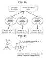
- a part of the field of outside viewis viewed through that columnar transparent member, there is inconvenience that stray light that renders an image substantially hard to see is likely to occur by unnecessary reflected light. That is, as shown in FIG. 27 , for instance when a mountain far in the horizontal direction is viewed, light rays from the sun above are incident on the columnar transparent support member 100 , whereupon the internally reflected light will be seen as unnecessary light 101 . This leads to a problem that an unpleasant image will be seen upon seeing-around.
- a head mount type image display systemat least comprising a display device, an eyepiece optical system, an eyepiece window, an eyepiece window holder, a casing and a supporter for fixing all these components onto a user's head, characterized in that a light source illuminates said display device, said casing covers said display device, said eyepiece window holder holds said eyepiece window within a user's field of view, said eyepiece optical system forms a virtual image of an image displayed on said display device, said eyepiece window is a window through which a light beam to form said virtual image leaves toward a user's eye, and a member that forms said eyepiece window holder is configured as a see-around type having a length of 10 mm or greater, wherein a width of projection section in a user's visual axis direction is 4 mm or less except some projection.
- Dis the diagonal size of an effective display surface of the display device
- fis the focal length of the eyepiece optical system
- the light source adapted to illuminate the display devicecould be formed of a fluorescent resin rod.
- the member that forms the eyepiece window holderis constructed such that its width of projection section in the user's visual axis is set to 4 mm or less, and that it is thinner than a human average pupil diameter (4 mm).
- the see-through effectis achievable because the outside is not fully cut off.
- a site with electronic images displayedbecomes dim enough to improve on the visibility of electronic images, because some light beams from the outside are blocked off by the member that forms the eyepiece window.
- the field of outside viewis not cut off at all, so that a clear-cut, bright field of view is achievable as if the system of the invention were not present. Furthermore, because the system of the invention is thinner than the pupil diameter so that the wearer's eyes are not fully covered, the wearer's more natural expressions would come through.
- the first embodiment of the inventionis directed to a head mount type image display system at least comprising a display device, an eyepiece optical system, an eyepiece window, an eyepiece window holder, a casing and a support for fixing all these parts onto a user's head, wherein said casing covers said display device, said eyepiece window holder holds said eyepiece window within a user's field of view, said eyepiece optical system form a virtual image of an image displayed on said display device, said eyepiece window allows a light beam for forming said virtual image to be directed to a user's eye and leave it, and a member that forms said eyepiece window holder is such that, in a range of 10 mm or greater from said eyepiece window toward a base, a width of projection section in a visual axis direction of a user is 4 mm or less except some projection, and has a see-around mechanism.
- the eyepiece window holder 2that is a sort of shield matter positioned in front of the eyeball E is constructed in such a way as to have a length of 10 mm or greater and be thinner than the human being's average pupil diameter of 4 mm; as shown in FIG. 6 , light beams from the outside are not completely cut off, so that an outside image on the side of the eyepiece window holder 2 that faces away from the eyeball E is visible as if it were seen through the eyepiece window holder 2 . Because extraneous light is unlikely to pass through the interior of the eyepiece window holder 2 , it is possible to eliminate unnecessary reflection that is a problem with the prior art. That is, there is the see-around effect obtainable, which has the features of:
- the head mount type image display system as recited in the first embodimentis further characterized in that the member that forms the eyepiece window is constructed such that the width of projection section in the user's visual axis direction is 4 mm or less, and has a see-through function.
- the member that forms the eyepiece windowis kept smaller than the human being's average pupil diameter of 4 mm; as shown in FIG. 6 , an outside image away from the member that forms the eyepiece window can be visible as if it were seen through that member.
- the light beams of an electronic imageleave from the eyepiece window, so that the outside image and electronic image are visible in an overlapping way. That is, there is the see-through effect obtainable.
- the see-through effectis achievable. Nonetheless, the additional features of:
- the site with electronic images displayedbecomes dim enough to improve on the visibility of electronic images, because some light beams from the outside are blocked off by the member that forms the eyepiece window. Accordingly, the brighter the outside, the more the user's pupil is constricted and, hence, the more the quantity of the light blocked becomes, resulting in an enhanced action on the maintenance of visibility.
- the head mount type image display system according to the first embodimentis further characterized in that between said eyepiece window holder and said eyepiece window, there is a total reflection mirror or prism located, which is adapted to bend an optical axis in the user's eye direction.
- the head mount type image display systemaccording to any one of the first to the third embodiment is further characterized in that said eyepiece window holder is held in such a way as to be substantially horizontally located upon mounted onto the head.
- the head mount type image display system according to the third embodimentis further characterized in that the whole of said eyepiece window and said total reflection mirror or the whole of said eyepiece window and said total reflection prism has a rotation mechanism, by which their rotation can be adjusted with the longitudinal direction of said eyepiece window holder as a rotation axis.
- the head mount type image display system according to the third embodimentis further characterized by comprising a rotation mechanism, by which the user can adjust the rotation of said display device with the direction vertical to the display surface of said display device as a rotation axis.
- the rotation of the display devicecauses an image viewed through the head mount type image display system to have a tilt in the horizontal direction.
- the display deviceis adjusted by rotation with the direction vertical to the display surface of the display device as the rotation axis, it is then possible to erect that image.
- the head mount type image display systemaccording to any one of the 1 st to the 6 th embodiment is further characterized in that a part or the whole of said eyepiece optical system is integral with said eyepiece window.
- an optical element countcan be decreased with a lot more simplified structure, so that the width of the member that forms the eyepiece window can be easily set to 4 mm or less.
- the head mount type image display systemaccording to any one of the 1 st to the 7 th embodiment is further characterized in that a part or the whole of said eyepiece optical system is built in said eyepiece window holder.
- the eyepiece optical systemis built in the eyepiece window supporter, it is then possible to dispense with any special space for storing the eyepiece optical system, thereby slimming down the head mount type image display system.
- the head mount type image display system according to the 8 th embodimentis further characterized in that said eyepiece optical system built in said eyepiece window holder is an optical system that has an action of converging a parallel light beam.
- the diffusion of the necessary light beamcan be held back if the optical system having an action of converging a light beam is built in there, whereby the light beam can be passed through while its diameter is decreased.
- the member that forms the eyepiece window supportercan be easily designed to have a width of 4 mm or less.
- the head mount type image display systemaccording to any one of the 1 st to the 9 th embodiment is further characterized in that said eyepiece window has a rectangular shape whose long side is in the same direction as the longitudinal direction of said eyepiece window holder.
- the whole of the eyepiece optical system portioncan be slimmed down, and by making it horizontally long (in the longitudinal direction of the eyepiece window holder), a wide eye point is ensured for easy position adjustment.
- an increase in the quantity of light brought in from the eyepiece windowenables bright images to be viewed.
- the head mount type image display systemaccording to any one of the 1 st to the 9 th embodiment is further characterized in that said eyepiece window has an aperture size that is smaller than the pupil diameter in the vertical direction and larger than the pupil diameter in the horizontal direction.
- the see-through effectis further obtainable by making that aperture size smaller than the pupil diameter in the vertical direction.
- the head mount type image display systemaccording to any one of the 1 st to the 9 th embodiment is further characterized in that said eyepiece window has an aperture size that is 4 mm or less in the vertical direction and 4 mm or greater in the horizontal direction.
- the aperture size of the eyepiece windowbe 4 mm or less in the vertical direction and 4 mm or greater in the horizontal direction. This ensures that the advantages of the head mount type image display systems according to the 10 th and the 11 th embodiment are easily achievable.
- the head mount type image display systemaccording to any one of the 1 st to the 9 th embodiment is further characterized in that said casing and said eyepiece window holder are joined together by way of a total reflection mirror or prism, or an image fiber bundle.
- the casing adapted to cover the display device and the eyepiece window holderare joined together by way of a total reflection mirror or prism, or an image fiber bundle, it enables the casing to be mounted on the user's temple side.
- the head mount type image display systemWhen the head mount type image display system is not in use, it can be bent along that portion into a compact form for easy storage or carrying.
- the head mount type image display systemaccording to any one of the 1 st to the 13 th embodiment is further characterized in that there is an illumination portion, and said illumination portion and said casing are joined together by way of a total reflection mirror or prism, a light guide sheet, or a light guide.
- the casingcan be located on the user's temple side.
- the head mount type image display systemWhen the head mount type image display system is not in use, it can be bent along that portion into a compact form for easy storage or carrying.
- the head mount type image display system according to the 9 th embodimentis further characterized in that said eyepiece optical system comprises a convex lens.
- the positive power of the convex lensis going to form a virtual image of the display device that the viewer can view.
- the head mount type image display system according to the 8 th and the 9 th embodimentis further characterized in that said eyepiece optical system comprises an optical medium whose refractive index grows gradually high in a radial direction.
- the optical medium whose refractive index grows gradually high in the radial directionis used for the eyepiece optical system, it makes it easy to design the member that forms the eyepiece window supporter in the form of a thinner arrangement of 4 mm or less, because that optical medium has an action of converging a light beam.
- the head mount type image display system according to the 1 st to the 16 th embodimentis further characterized by satisfying D/f ⁇ 0.5, where D is the diagonal size of an effective display surface of the display device, and f is the focal length of the eyepiece optical system.
- FIG. 14is illustrative of relations among various parameters of the display system according to the invention.
- the exit pupil of the display systemis positioned near the eyepiece window or between the eyepiece window and the pupil of the user's eye, it is then possible to reduce the shading of light beams at the periphery of the image under observation. Even so, as D/f exceeds 0.5, it causes shading to take place.
- the optical system in the display system of the inventionto satisfy the condition D/f ⁇ 0.5, because it is then possible to achieve a display system that, albeit being a small-format system, enables electronic images to be viewed without shading.
- the head mount type image display system according to the 17 th embodimentis further characterized in that the exit pupil is positioned near the eyepiece window or between the eyepiece window and the pupil of the user's eye.
- the head mount type image display system according to the 1 st embodimentis further characterized in that an electronic image-formation light beam leaving the display device passes outside of the eyepiece window holder.
- the member that forms the eyepiece window supportercannot be thinner than the thickness of the diameter of that light beam.
- the electronic image-formation light beamis permitted to pass outside of the eyepiece window holder, it is then possible to design the ideal see-around arrangement, because the member that forms the eyepiece window supporter is free from such limitation.
- the head mount type image display system according to the 1 st embodimentis further characterized by comprising an illuminating light source adapted to illuminate the display device, wherein said light source is made up of a fluorescent resin rod.
- a fluorescent resin rodemits light through self-luminescence upon irradiation with extraneous light, and the emitted light is subjected to total reflection within the rod, leaving its end face.
- the head mount type image display system according to the 20 th embodimentis further characterized in that the end face of the fluorescent resin rod that faces away from the display device is mirror coated or configured into a corner cube shape.
- the opposite end face of the fluorescent resin rodis mirror coated or configured into a corner cube shape, it is then possible to reflect light that otherwise will go out in the opposite direction and reuse that light as illuminating light for the display device.
- the head mount type image display system according to the 20 th embodimentis further characterized in that there is a mirror located on the side of said fluorescent resin rod, on which no extraneous light is incident.
- the head mount type image display systemaccording to any one of the 1 st to the 22 nd embodiment is further characterized in that the user's eye and said eyepiece window are positioned in such a relation that the visual axis of the eye does not overlap said eyepiece window, and a chief light ray through said eyepiece window is incident within a pupil diameter.
- the head mount type image display system according to the first embodimentis further characterized in that the member that forms said eyepiece window holder has a tapered structure such that said member grows thin on the eyepiece window side and thick on the display device side.
- the see-around or see-through functionbecomes effective.
- small-size display devicesare very hard to fabricate, and their fabrication costs much. Accordingly, if the eyepiece window portion is kept as thin as 4 mm or less and the base portion away from the eyeball is made thick, it is then possible to increase display device size while the see-around or see-through function is kept intact.
- the head mount type image display system according to the first embodimentis further characterized in that a secondary image formed by transmission of an image on said display device by way of an optical fiber image guide is viewed through said eyepiece window holder and said eyepiece window.
- the image on the display deviceis transmitted using the optical fiber image guide to form it as a secondary image for viewing, it is then possible to space the display device and electric substrates away from the eye, getting rid of the apparent unnaturalness of the display system upon wearing.
- the head mount type image display system according to the 25 th embodimentis further characterized in that an encrypted optical fiber image guide with irregularly arranged optical fibers is used as said optical fiber image guide, and in correspondence to said encrypted optical fiber image guide, an image is displayed on said display device in such a way as to view a secondary image as an image.
- the head mount type image display system according to the 25 th embodimentis further characterized in that the pitch of each pixel of said optical fiber image guide differs between on the entrance side and on the exit side such that a secondary image transmitted by way of said optical fiber image guide becomes smaller in size than an image on said display device.
- the eyepiece window holder or the eyepiece windowis as thin as 4 mm or less; a small-size display device fit for them is hard to fabricate, and its fabrication costs much. Therefore, if the pitch of the array of pixels on both end faces of the optical fiber image guide is varied, it is then possible to generate a secondary image smaller in size than an image on the display device. This in turn makes it possible to use a display device of larger size, thereby achieving significant cost reductions.
- the head mount type image display systemaccording to any one of the 1 st to the 27 th embodiment is further characterized in that a display portion including said display device, said eyepiece window holder, said eyepiece optical system and said eyepiece window are built in a spectacle frame.
- the head mount type image display system of the inventionis so reduced in size and weight that its main parts can be built in spectacles in an integral way.
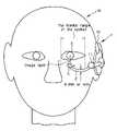
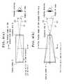
- FIG. 1is illustrative in schematic of a head mount type image display (image display system) 1 according to one example of the invention, which is mounted on the head M of the user.
- FIG. 2( a )is illustrative of the profile of the user in FIG. 1
- FIG. 2( b )is a view of the user as viewed from above.
- a small-size headphone type head supporter 10is utilized.
- an eyepiece window holder 2 with a built-in light guidance path adapted to enable a display panel positioned at the end of the face to be viewedextends from the head supporter 10 to the vicinity of the front of the eyeball E.
- all components positioned in the frontal range of the eyeballare set to a width of 4 mm or less.
- the pupil diameter of a human beingchanges between 2 mm and 8 mm depending on brightness.
- a shield matter located at the front of the eyeballscenes in the distance can be viewed without being obstructed by that shield matter.
- a member that forms the eyepiece window holder 2 that is a casing component positioned in the frontal range of the eyeballto a size of 4 mm or less on the basis of an average pupil diameter size, the outside could be viewed without being obstructed in most of ordinary environments of use.
- the head supporter 10 extending in a rod formmay be made up of a fluorescent resin rod, as will be described later.
- the headphone type head supporter 10may include inside an auxiliary illuminating light source, a display panel drive substrate, various control substrates, various information processing substrates, a memory, a communications function, a speaker, an operating interface, etc.
- FIG. 3is a schematic view of an exemplary arrangement wherein any light guidance path is not built in the eyepiece window holder 2 , as viewed from the front.
- This arrangementis comprised of an image exit portion 11 held to the head supporter 10 , with the display panel attached to it, the eyepiece window holder 2 held to the head supporter 10 to hold an eyepiece optical system 5 , and the eyepiece optical system 5 held to the eyepiece window holder 2 .
- Light leaving the display panelpasses the outside of the eyepiece window holder 2 , i.e., through the air, rather the inside thereof, entering directly the eyepiece optical system 5 .
- the eyepiece window holder 2here, too, is set to a width of 4 mm or less and a length of 10 mm or greater, as viewed from the frontal range of the eyeball.
- FIG. 3With the example of FIG. 3 , not only is the advantage of FIGS. 1 and 2 obtained, but also both the outside and an electronic image can be viewed in a more natural way, because the eyepiece window holder 2 is located outside of an optical path and spaced away from the center of the field of view.
- FIG. 4( a )is a perspective view of the optical system portion in the arrangement of FIG. 1
- FIG. 4( b )is a view of that optical system portion as viewed from above.
- Image light leaving a display panel 3 built in the vicinity of the entrance end of the eyepiece window holder 2passes through the interior of the eyepiece window holder 2 , turning direction at a reflecting member 5 and entering an eyepiece window 4 , leaving it in the direction of the eyeball E.
- the left end of the eyepiece window holder 2is actually linked to the head supporter 10 , whereby it is held to the head M.
- the eyepiece window holder 2here is set to a width of 4 mm or less and a length of 10 mm or greater, as viewed in the direction of the viewer.
- Any desired membercould be used for the reflecting member 6 here provided that it is capable of reflecting light rays; for instance, a prism or a mirror could be used.
- Any desired small-format display panelcould be used for the display panel 3 here; for instance, use could be made of a transmission or reflection type liquid crystal display device, and a self-emission type organic or inorganic EL device.
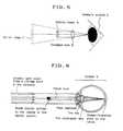
- FIG. 5is illustrative of one basic arrangement of the head mount type image display system according to the invention.
- the display panel 3is located at a position before the near point adjustment limit, and image light from it is projected by an eyepiece lens 5 onto the eyeball E, so that the viewer can view an aerial image 3 ′ that is a virtual image of an image on the display panel 3 on a magnified scale.
- Such arrangementensures that even with a small-format display panel (display panel 3 ), an image displayed on it can be viewed at a large angle of view.
- any desired optical systemcould be used for the eyepiece lens 5 provided that it has a positive refracting power; for instance, a convex lens, a concave mirror, and an index-inhomogeneous lens could be used.
- a positive lens groupcomprising a combination of multiple optical elements having a positive or negative refracting power could be used for that convex lens 5 .
- FIG. 6is illustrative in schematic of how the outside is shielded by the display system of the invention.
- FIG. 6teaches a principle of, even when there is a sort of shield matter (the casing of the display system in this example: primarily corresponding to the eyepiece window holder 2 in FIGS. 1 to 4 ) found at the front of the eyeball E, why an outside image in the distance is not perfectly shielded off on condition that the shield matter is thinner than the pupil diameter.
- light coming from a point in the distanceis incident light.
- this lightis incident on the eyeball E as substantially parallel light.
- the shield matteris smaller than the pupil diameter, a part of parallel light passes through the pupil, forming an image on a corresponding point on the retina. Therefore, even with the shield matter (the casing of the display system) or the like found at the front of the eyeball, outside information can be viewed without being lost (the see-through feature) on condition that it is thinner than the pupil diameter.
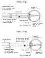
- optical axis (visual axis) of the eyeball of the user who views the outsideis mutually parallel with the optical axis of the display system of the invention as shown typically in the optical path diagram of FIG. 7( b ), an outside image could then be seen as if the image on the displays system of the invention overlapped it (the see-through feature).
- the eyepiece window holder 2that is a sort of shield matter positioned in front of the eyeball E is constructed in such a way as to have a length of 10 mm or greater and be thinner than the human being's average pupil diameter of 4 mm; as shown in FIG. 6 , light beams from the outside are not completely cut off, so that an outside image on the side of the eyepiece window holder 2 that faces away from the eyeball E is visible as if it were seen through the eyepiece window holder 2 . Because extraneous light is unlikely to pass through the interior of the eyepiece window holder 2 , it is possible to eliminate unnecessary reflection that is a problem with the prior art. That is, there is the see-around effect obtainable, which has the features of:
- FIG. 8( a )is illustrative of its basic arrangement that is comprised of the eyepiece window holder 2 adapted to guide light from the display panel 3 , the reflecting member 6 adapted to turn it toward the direction of the eyeball, and the eyepiece lens 5 .
- This structureensures that the bulky display panel 3 is spaced away from the eyeball as much as possible so that the width of the site included in the frontal range of the eyeball can be narrowed down.
- FIG. 8( a ) structurethere are problems that the size of the display panel 3 is limited by the diameter of the member that forms the eyepiece window holder 2 , and when the length of the eyepiece window holder 2 is increased, it is impossible to make the angle of the view of the display screen large.
- the member that forms the eyepiece window holder 2is configured into a tapered structure, as shown in FIG. 8( b ), it is then possible to narrow the portion positioned in the frontal range of the eyeball as much as possible and make the portion of the display panel 3 large. As a result, it is possible to use the display panel 3 that has an easy-to-fabricate size and take advantage of a large angle of view.
- FIGS. 9( a ) and 9 ( b )are illustrative of an angle-of-view difference between the structures shown in FIG. 8( a ) and FIG. 8( b ). More specifically, FIG. 9( a ) is illustrative of the structure of a casing 2 1 having the same diameter all across, which forms part of the eyepiece window holder 2 , and FIG. 9( b ) is illustrative of a casing 2 2 having a tapered structure that is thin on the eyepiece lens 5 side and thick on the display panel 3 side. For instance, consider here the condition under which a portion from near the center of the casing 2 1 , 2 2 to the eyepiece lens 5 comes within the front range of the eyeball.
- FIG. 9( a )From a comparison of FIG. 9( a ) with FIG. 9( b ), it is found that even when the diameter of both the casings within the frontal range of the eyeball is 4 mm or less, the casing 2 2 of FIG. 9( b ) having a tapered structure is more preferable, because there is a larger angle of view obtainable with an increase the size of the display plane 3 .
- an optical axisis indicated by reference numeral 21
- a light ray from the end of the display panel 3by reference numeral 22 .
- the casing within the frontal range of the eyeballas thin as possible, the outside can be viewed more clearly, and by increasing the size of the display panel 3 , the angle of view can be so increased that a lot more information can be presented, and the fabrication of the display panel 3 can be facilitated as well.
- the smaller the size of an aperture portion of the eyepiece lens 5the smaller the display system of the invention can become, resulting in a structure that is of lower weight and less likely to cover the wearer's eye.
- the casing of the display system that is a sort of shield matter to the eyeballbecomes small, it enables the see-through effect to be obtained in a more natural way, and the natural expressions of the wearer to be more easily conveyed to a third person.
- FIG. 10( a )that is a perspective view of the exemplary arrangement of FIG. 8
- FIG. 10( b )that is illustrative of the position of the eyeball E with respect the tip of the eyepiece window holder 2 upon viewing
- FIG. 10( c )that is illustrative of the relation of the eyepiece window 4 to pupil diameter size again upon viewing, because size reductions, improvements in the see-through effect, etc. are achievable, and demerits such as luminance drops can be minimized as well.
- the eyepiece window 4 of the eyepiece lens 5is configured into a rectangular shape that becomes long in the longitudinal direction of the eyepiece window holder 2 , it is then possible to achieve a head mount type image display system that is diminished in size, improved in the see-through effect, and free of luminance drops, and is easier to use as well.
- the eyepiece window 4With the see-through effect intact. Then, its size should preferably be smaller in the vertical direction, and larger in the horizontal direction, than the pupil diameter. Because the human being's average pupil diameter is 4 mm, it is preferable to use the eyepiece window 4 that satisfies the condition that its vertical size is 4 mm or less and its horizontal size is 4 mm or greater, because there are easy-to-see displays obtainable in a lot more viewing situations.
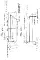
- FIG. 11is illustrative of the horizontal width of an eye point depending on the horizontal length of the eyepiece window 4 .
- the eyepiece window 4becomes longer in the horizontal direction (the longitudinal direction of the eyepiece window holder 2 ) as shown in FIG. 11( b )
- the eye pointthen becomes wider as compared with where the horizontal size of the eyepiece window 4 of FIG. 11( a ) is smaller, so that the position of the eye with respect to the eyepiece window 4 is more easily adjusted, and the quantity of light brought in from the eyepiece window 4 becomes larger, making it possible to view brighter images.
- FIG. 12is illustrative of an exemplary arrangement where two reflecting members 6 , 6 ′ are used in the optical path through the eyepiece window holder 2 . Bending the optical path twice by two reflecting members 6 , 6 ′ is often effective for the location of a back light, and the link of the eyepiece window holder 2 to the head supporter 10 . In other words, the optical path being bent twice contributes to an increase in the degree of flexibility in layout.
- FIG. 13is illustrative of an example of building an optical system in the eyepiece window holder 2 , wherein a gradient index lens 23 is used for that optical system.
- a gradient index lens 23By use of such a gradient index lens 23 , a display surface having an increased angle of view is achievable at the diameter of the thin eyepiece window holder 2 rather than with the eyepiece optical system comprising an ordinary convex lens.
- FIG. 13( b )shows an angle of view at the time when the eyepiece optical system is made up of the ordinary eyepiece lens (convex lens) 5
- FIG. 13( c )shows an angle of view at the time when it is made up of the gradient index lens 23 .
- the gradient index lens 23as the eyepiece optical system in the eyepiece window holder 2 , a larger angle of view is achievable at a thinner diameter.
- FIG. 14is illustrative of relations among various parameters of the display system in the display system according to the invention.
- the exit pupil of the display systemis positioned near the eyepiece window or between the eyepiece window and the pupil of the user's eye, it is then possible to reduce the shading of light beams at the periphery of the image under observation. Even so, as D/f exceeds 0.5 that is the upper limit to inequality (5), it causes shading to take place.
- the optical system in the display system of the inventionto satisfy the condition D/f ⁇ 0.5, because it is then possible to achieve a display system that, albeit being a small-format system, enables electronic images to be viewed without shading.
- illuminating light sourcefor the display panel 3 of the display system according to the invention, it is desired to make use of extraneous light.
- that illuminating light sourcemay be made up of a fluorescent resin rod, as set forth below.
- FIG. 15is illustrative of the fluorescent resin rod adapted to use extraneous light as back light.
- the fluorescent resin rod indicated by 30is a member obtained by processing a resin containing a fluorescent substance 41 into a rod form. As extraneous light 42 is incident on the side or the like of that fluorescent resin rod 30 , it is once absorbed in the fluorescent substance 41 , and then, light is emitted with that fluorescent substance 41 as a light source.
- light 43 emitted from insideis subjected to repetitive total reflections at its internal side, leaving the end face of the rod. In other words, the light emitted inside, and confined within, the rod leaves the rod's end face, so that the rod's end face gives out very bright light.
- the lightwill be emanated out of the end face of the rod that faces away from the end face of the rod with light as back light.
- the unavailable end faceis configured as a mirror 44
- light reflected at itwill be then emanated out of the available end face only, so that such light can be effectively used as back light.
- a metal thin filmcould be vapor deposited onto the rod's end face, or a prism harnessing total reflection like a corner cube could be used.
- extraneous light 42 incident from the side of the member processed into a rod formis not absorbed in the fluorescent substance 41 , or light that does not satisfy the total reflection condition for the rod leaks out of the side.
- the mirror 45is located on the side on which the extraneous light 42 is not incident or the portion that turns inside upon mounting, then a part of unused light can be reused.
- illuminating light obtained with that rod arrangementis used as illuminating light 46 for the display panel 3 , it causes the brightness of illuminating light 46 to change depending on the brightness of the outside. This phenomenon is in coincidence with an available scene at the time of using the see-through function, generally where when the outside is bright, bright illumination is needed, and when the outside is dark, dim illumination is only needed.
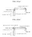
- FIGS. 16 and 17are illustrative of exemplary arrangements of the display system that utilizes such a fluorescent resin rod 30 .
- illuminating light leaving the end face of the fluorescent resin rod 30is incident on the display panel 31 or 36 , and image light from the display panel 31 or 37 makes its way through the eyepiece window holder 2 , leaving the eyepiece window 4 .
- the fluorescent resin rod 30here is connected to the head supporter 10 or, alternatively, the fluorescent resin rod 30 per se could be used as part of the head supporter 10 .
- FIGS. 16( a ), 16 ( b ) and 17 ( a )are illustrative of an exemplary arrangement that incorporates a transmission type display panel 31
- FIG. 17( b )is illustrative of an exemplary arrangement that incorporates a reflection type display panel 36
- an optical path split optical element 49such as a half-silvered mirror is located on the display side of the reflection type display panel 36 .
- FIG. 18is illustrative of an exemplary arrangement where a fluorescent resin member and a light guidance sheet are combined into a display panel back light.
- an exit groove 47is provided in a part of a fluorescent resin sheet 30 ′ configured into a sheet form, so that light leaving that portion can be used as back light for the display panel 31 .
- light leaving one end of the fluorescent resin rod 30is entered in a light guidance sheet 48 that is another member connected to the fluorescent resin rod 30 , and light guided toward the display panel 31 leaves the side of the light guidance sheet 47 , thereby illuminating the display panel 31 .
- the fluorescent resin memberis combined with the light guidance sheet, it is then possible to use extraneous light to illuminate the display panel. Further, by use of such a light guidance sheet, it is possible to provide uniform illumination all across the display panel even when the end face of the fluorescent resin rod is smaller than the display panel.
- the fluorescent resin memberas back light, extraneous light can be utilized for the illumination of the display panel, so that there can be lower power consumption. Further, because the quantity of illuminating light changes naturally depending on the brightness of the outside, proper illumination is achievable depending on available environments yet without recourse to any special sensor. Furthermore, a back light that utilizes extraneous light can be fabricated at lower costs.
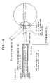
- FIG. 19is illustrative of another exemplary arrangement using the fluorescent resin rod 30 .
- a transmission type liquid crystal display device 31is used as the display device, and the aforesaid fluorescent resin rod 30 is used for the illumination of that display device 31 .
- the fluorescent resin rod 30emits light through self-fluorescence upon irradiated with extraneous light, and the ensuing light is subjected to total reflection inside the fluorescent resin rod 30 , leaving its end face. That light travels through a reflecting prism 33 and an illuminating lens 32 to illuminate the display device 31 by illuminating light from self-fluorescence.
- the end face of the fluorescent resin rod 30 that faces away from the transmission type liquid crystal display device 31is configured into the shape of a total reflection prism (corner cube) 34 , so that fluorescent light traveling away from the display device 31 is turned back for reuse.
- a total reflection type transparent rod 9 that is 90° at one endis located between the display device 31 and the eyepiece window 4
- a convex lens 15 that forms an eyepiece lensis applied onto the position of the eyepiece window 4 at an exit end where the optical path through the transparent rod 9 is bent 90°, and the whole is covered up with the eyepiece window holder 2 .
- the convex lens 15here that is an eyepiece lens is integral with the eyepiece window 4 .
- the power consumption of the head mount type image display systemcan be kept lower. Further, when the outside is bright, the luminance of the light source grows high, thereby eliminating an inconvenience that an electronic image is outdone by the brightness of the outside and so becomes hard to be visible.
- the fluorescent resin rod 30when it is not in use, it can be folded down in a direction indicated by an arrow with a hinge rotation shaft 35 as a center for storage. This arrangement ensures that the fluorescent resin rod is folded down together with spectacles for storage.
- FIG. 21is illustrative of an example wherein the head mount type image display system of the invention is mounted on ordinary spectacles.
- the fluorescent resin rod 30is disposed along a spectacle frame 50 . Light from the rod's end face is once bent by the reflecting member to 90°, and entered in the display panel 31 . Image light from the display panel 31 is guided through the eyepiece window holder 2 , leaving the eyepiece window 4 .
- Other end face of the fluorescent resin rod 30here could be provided with a mirror 44 so as to make more efficient use of light.
- a mirror 45could be disposed at a boundary, upon which extraneous light 42 does not strike, between the spectacle frame 50 and the fluorescent resin rod 30 .
- auxiliary light source 37is utilized, it is then possible to use the spectacles even in quite a dark place.
- the auxiliary light source 37is disposed at the other end of the fluorescent resin rod 30 for the purpose of using the mirror 44 and the auxiliary light source 37 in a switchover way.
- the light emanating from the auxiliary light source 37should preferably be in coincidence with a wavelength band at which the fluorescent substance of the fluorescent resin rod 30 can be excited, whereby the fluorescent resin rod 30 is efficiently excited by auxiliary light from the auxiliary light source 37 .
- This in turnallows the display panel 31 to be illuminated by this fluorescence; the auxiliary light source 37 makes sure bright illumination at lower power consumption.
- the wavelength of light emitted by the auxiliary light source 37should preferably not be at a wavelength band at which the absorptance of the fluorescent resin rod 30 grows large. This enables the display panel 31 to be illuminated without the light emitted by the auxiliary light source 37 being absorbed in the fluorescent resin rod 30 ; the auxiliary light source 37 makes sure bright illumination at lower power consumption.
- the color of light emitted by the auxiliary light source 37could be different from the fluorescent color emitted by the fluorescent resin rod 30 . This ensures that whenever necessary, the user's attention may be drawn by putting the auxiliary light source 37 on and off. By this blinking operation, the image being viewed by the user changes in terms of not only brightness but also color, drawing the user's attention.
- the head mount type image display system of the inventionBy mounting the head mount type image display system of the invention to ordinary eyeglasses, it is possible for even an ordinary spectacle wearer to make use of the head mount type image display system of the invention.
- the image display systemis provided with the auxiliary light source, then it can address dark environments as well.
- the fluorescent resin rodis used as the illuminating light source that utilizes extraneous light and the auxiliary light source is selected in consideration of the wavelength absorbed by its fluorescent resin, it is then possible to make power consumption low.
- the auxiliary light sourcethat emits light having a wavelength different from that of the fluorescent color of that fluorescent resin is used, it may be used as a warning signal.
- wirings, substrates or the likeare located on the side of the fluorescent resin rod that faces away from the portion adapted to receive light, there is no obstacle to the incidence of light.
- FIG. 22is illustrative of an example of incorporating the head mount type image display system of the invention in a spectacle frame.
- the eyepiece window holder 2is built in spectacle frames 50 .
- FIG. 23is illustrative of an exemplary arrangement utilizing an optical fiber image guide.
- the display panelhas been located near the eye; the components located near the eye have become bulky. Therefore, if the display panel 3 is spaced away from near the eye and an image from the display panel 3 is transmitted as a secondary image through an optical fiber image guide 55 to near the eye so that the transmitted secondary image can be viewed by the optical system on a magnified scale, it is then possible to diminish the components located near the eye as much as possible.
- the optical fiber image guide 55because of having some pliability, could be used even in a folded state well compatible with various designs and adjustment mechanisms.
- FIG. 23is illustrative of how the display panel 3 receives, and displays, images or information from a controller 56 radio connected to it.
- the controller 56here is understood to refer to an exclusive controller, a cellular phone, a personal digital assistant (PDA), and all.
- the optical fiber image guideby transmitting an image from the display panel as a secondary image by way of the optical fiber image guide, it is not necessary to locate the display panel, wirings, electric substrates or the like near the eye; it is possible to prevent the components near the eye from growing bulky, which have an adverse influence on the sense of wearing or designs. Further, the optical fiber image guide, because of having some pliability, could be used even in a folded state well compatible with various designs and adjustment mechanisms.
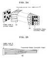
- FIG. 24is illustrative of the arrangement and operation of an encrypted optical fiber image guide 37 .
- An ordinary optical fiber image guideis adapted to transmit an image displayed on the display panel 3 while its pattern is kept. For instance, with one optical fiber meted per pixel on the display panel 3 , the image is transmitted while the relative locations of pixels are maintained.
- the encrypted optical fiber image guidehere is understood to refer to one wherein one optical fiber 58 is allocated to one pixel on the display panel 3 , and in the course of transmission, the relative locations of the optical fibers 58 are interchanged at random, thereby displaying an image quite different in pattern from the image on the display panel 3 .
- FIG. 23there is quite a nonsense image displayed on the display panel 3 , but the locations of the optical fibers 58 for the transmission of it are mutually interchanged, so that there is a capital “F” displayed on a secondary image after that transmission.
- FIG. 25is illustrative of an image compression optical fiber image guide 55 ′.
- very small display panelsare difficult to fabricate, and cost much, eve if somehow fabricated. Therefore, if a display panel of easy-to-fabricate size is mounted on a less obstructive site and a secondary image smaller than the display panel 3 is formed by the image compression optical fiber image guide 55 ′ to view it through an optical system, it is then possible to achieve a head mount type image display system that, albeit using a large display panel, can be mounted on a compact site near the eye.
- an image smaller than a practical display panelcan be displayed as a secondary image near the eye.
- an extremely small display panelis used; however, the use of the image compression optical fiber image guide ensures that an easy-to-fabricate, somewhat large display panel can be used at a reasonably low cost.
- FIG. 26is illustrative in schematic of contents distribution for a system that incorporates such an encrypted optical fiber image guide as shown in FIG. 24 .
- a contents distribution centerhas information on the encryption code corresponding to the respective product numbers, and carries out image processing on the basis of it. And then, the center distributes the processed contents data to a person who has a certain specific product number. As a consequence, that contents data can be reproduced by, and viewed through, a product having a certain specific number alone. When such contents data are copied to another product or illegally obtained, quite a nonsense image will be only obtained upon reproduction on another product. Therefore, it is possible to resolve a problem with illegal copying or use that arises in digital contents distribution.
- the aforesaid head mount type image display system of the inventionmay be embodied as follows.
- a head mount type image display systemat least comprising a display device, an eyepiece optical system, an eyepiece window, an eyepiece window holder, a casing and a supporter for fixing all these components onto a user's head, wherein said casing covers said display device, said eyepiece window holder holds said eyepiece window within a user's field of view, said eyepiece optical system forms a virtual image of an image displayed on said display device, said eyepiece window allows a light beam for forming said virtual image to be directed to a user's eye and leave it, and a member that forms said eyepiece window holder is such that, in a range of 10 mm or greater from said eyepiece window toward a base, a width of projection section in a user's visual axis direction is 4 mm or less except some projection, and has a see-around mechanism.
- a head mount type image display systemas recited in any one of [1] to [3] above, characterized in that said eyepiece window holder is held in such a way as to be substantially horizontally located upon mounted onto the head.
- a head mount type image display systemas recited in any one of [1] to [6] above, characterized in that a part or the whole of said eyepiece optical system is integral with said eyepiece window.
- a head mount type image display systemas recited in any one of [1] to [7] above, characterized in that a part or the whole of said eyepiece optical system is built in said eyepiece window holder.
- a head mount type image display systemas recited in any one of [1] to [9] above, characterized in that said eyepiece window has a rectangular shape whose long side is in the same direction as the longitudinal direction of said eyepiece window holder.
- a head mount type image display systemas recited in any one of [1] to [9] above, characterized in that said eyepiece window has an aperture size that is smaller than a pupil diameter in a vertical direction and larger than a pupil diameter in a horizontal direction.
- a head mount type image display systemas recited in any one of [1] to [9] above, characterized in that said eyepiece window has an aperture size that is 4 mm or less in a vertical direction and 4 mm or greater in a horizontal direction.
- a head mount type image display systemas recited in any one of [1] to [12] above, characterized in that said casing and said eyepiece window holder are joined together by way of a total reflection mirror or prism, or an optical fiber image guide.
- a head mount type image display systemas recited in any one of [1] to [13] above, characterized in that there is an illumination portion, and said illumination portion and said casing are joined together by way of a total reflection mirror or prism, a light guide sheet, or a light guide.
- a head mount type image display systemas recited in any one of [1] to [22], characterized in that the user's eye and said eyepiece window are positioned in such a relation that the visual axis of the eye does not overlap said eyepiece window, and a chief light ray through said eyepiece window is incident within a pupil diameter.
- a head mount type image display systemas recited in [25] above, characterized in that an encrypted optical fiber image guide with irregularly arranged optical fibers is used as said optical fiber image guide, and in correspondence to said encrypted optical fiber image guide, an image is displayed on said display device in such a way as to view a secondary image as an image.
- a head mount type image display systemas recited in any one of [1] to [27] above, characterized in that a display portion including said display device, said eyepiece window holder, said eyepiece optical system and said eyepiece window are built in a spectacle frame.
- FIG. 1is illustrative in schematic of the head mount type display according to one example of the invention, which is mounted on the user's head, as viewed from the front.
- FIG. 2( a )is a view of the profile of FIG. 1
- FIG. 2( b )is a view as viewed from above.
- FIG. 3is illustrative in schematic of an exemplary arrangement wherein the light guidance path is not built in the eyepiece window holder.
- FIG. 4( a )is a perspective view of an optical system portion in the arrangement of FIG. 1
- FIG. 4( b )is a view of that optical system portion as viewed from above.
- FIG. 5is illustrative of the basic arrangement of the optical system in the head mount type image display system according to the invention.
- FIG. 6is illustrative of the principles of the head mount type image display system according to the invention, whereby an outside image is visible as if it were seen through the eyepiece holder without a light beam from the outside being not perfectly cut off.
- FIG. 7is illustrative of why an outside image, too, can be naturally viewed by displacing a sort of shield matter from the frontal direction of the eyeball.
- FIG. 8is illustrative of an exemplary arrangement of the optical system built in the eyepiece window holder; FIG. 8( a ) is illustrative of its basic arrangement, and FIG. 8( b ) is illustrative of the member to form the eyepiece window holder, which is configured as a tapered structure.
- FIG. 9is illustrative of an angle-of-view difference between the structures of FIGS. 8( a ) and 8 ( b ).
- FIG. 10is a perspective view of the exemplary arrangement of FIG. 8
- FIG. 10( b )is illustrative of what relation the tip of the eyepiece window holder has to the eyeball at the time of viewing on that exemplary arrangement
- FIG. 10( c )is illustrative of what relation the eyepiece window has then to the pupil diameter size.
- FIG. 11is illustrative of the horizontal width of an eye point depending on the horizontal length of the eyepiece window.
- FIG. 12is illustrative of an exemplary arrangement wherein two reflecting members are used in the optical path through the eyepiece window holder.
- FIG. 13is illustrative of an exemplary arrangement wherein a gradient index lens is used for the optical system built in the eyepiece window holder.
- FIG. 14is illustrative of relations among various parameters of the optical system in the display system of the invention.
- FIG. 15is illustrative of a fluorescent resin rod for utilizing extraneous light for back light.
- FIG. 16is illustrative of an exemplary arrangement of the display system wherein the fluorescent resin rod is used.
- FIG. 17is illustrative of an exemplary arrangement of the display system wherein the fluorescent resin rod is used.
- FIG. 18is illustrative of an exemplary arrangement wherein a fluorescent resin rod and a light guidance sheet are combined together into a display panel's back light.
- FIG. 19is illustrative of another exemplary arrangement wherein the fluorescent resin rod is used.
- FIG. 20is illustrative of the arrangement of FIG. 19 in a folded-down state.
- FIG. 21is illustrative of an example wherein the head mount type image display system of the invention is attached to a pair of spectacles.
- FIG. 22is illustrative of an example wherein the head mount type image display system of the invention is incorporated in spectacle frames.
- FIG. 23is illustrative of an exemplary arrangement that incorporates an optical fiber image guide.
- FIG. 24is illustrative of the arrangement and operation of an encrypted optical fiber image guide.
- FIG. 25is illustrative of an image compression optical fiber image guide.
- FIG. 26is illustrative in schematic of contents distribution for a system in which such an encrypted optical fiber image guide as shown in FIG. 24 is used.
- FIG. 27is illustrative of problems with the prior art.
- Mthe human head
- Ethe eyeball 1: head mount type display (image display system) 2: eyepiece window holder 2 1: casing having the same diameter all across (eyepiece window holder) 2 2: casing having a tapered structure (eyepiece window holder) 3: display panel 3′: aerial image 4: eyepiece window 5: eyepiece optical system (eyepiece lens) 6, 6′: reflecting members 9: transparent rod 10: head supporter 11: image exit portion 15: convex lens 21: optical axis 22: light rays from the end of the display panel 23: gradient index lens 30: fluorescent resin rod 30′: fluorescent resin sheet 31: transmission type display panel (transmission type liquid crystal device) 32: illuminating lens 33: reflecting prism 34: total reflection prism (corner cube) 35: hinge rotation shaft 36: reflection type display panel 37: auxiliary light source 41: fluorescent substance 43: internally emitted light 44, 45: mirrors 46: illuminating light 49: optical path split optical element 47: exit groove 48: light guidance sheet 50: spectacle frames 51: spectacle lens 55
Landscapes
- Physics & Mathematics (AREA)
- General Physics & Mathematics (AREA)
- Optics & Photonics (AREA)
- Engineering & Computer Science (AREA)
- Multimedia (AREA)
- Signal Processing (AREA)
- Two-Way Televisions, Distribution Of Moving Picture Or The Like (AREA)
Abstract
Description
- [Patent Publication 1] JP(A)8-166557
- [Patent Publication 2] JP Domestic Publication No. 2003-502713
- [Patent Publication 3] U.S. Pat. No. 3,923,370
- [Patent Publication 4] U.S. Pat. No. 5,646,784
- [Patent Publication 5] 2000-196975
- [Patent Publication 6] JP(A)10-301055
- [Patent Publication 7] JP(A)8-313829
- [Patent Publication 8] JP(A)11-249067
ω/2=(D/2)/f (1)
ξ=(d/2)/W (2)
ω/2<ξ (3)
Then,
D/f<d/W (4)
D/f<0.5 (5)
ω/2=(D/2)/f (1)
ξ=(d/2)/W (2)
ω/2<ξ (3)
Then,
D/f<d/W (4)
D/f<0.5 (5)
| M: | the human head | ||
| E: | the eyeball | ||
| 1: | head mount type display (image display system) | ||
| 2: | eyepiece window holder | ||
| 21: | casing having the same diameter all across (eyepiece | ||
| window holder) | |||
| 22: | casing having a tapered structure (eyepiece window | ||
| holder) | |||
| 3: | display panel | ||
| 3′: | aerial image | ||
| 4: | eyepiece window | ||
| 5: | eyepiece optical system (eyepiece lens) | ||
| 6, 6′: | reflecting members | ||
| 9: | transparent rod | ||
| 10: | head supporter | ||
| 11: | image exit portion | ||
| 15: | convex lens | ||
| 21: | optical axis | ||
| 22: | light rays from the end of the display panel | ||
| 23: | gradient index lens | ||
| 30: | fluorescent resin rod | ||
| 30′: | fluorescent resin sheet | ||
| 31: | transmission type display panel (transmission type | ||
| liquid crystal device) | |||
| 32: | illuminating lens | ||
| 33: | reflecting prism | ||
| 34: | total reflection prism (corner cube) | ||
| 35: | hinge rotation shaft | ||
| 36: | reflection type display panel | ||
| 37: | auxiliary light source | ||
| 41: | fluorescent substance | ||
| 43: | internally emitted light | ||
| 44, 45: | mirrors | ||
| 46: | illuminating light | ||
| 49: | optical path split optical element | ||
| 47: | exit groove | ||
| 48: | light guidance sheet | ||
| 50: | spectacle frames | ||
| 51: | spectacle lens | ||
| 55: | optical fiber image guide | ||
| 55′: | image compression optical fiber image guide | ||
| 56: | controller | ||
| 57: | encrypted optical fiber image guide | ||
| 58: | optical fibers | ||
| 100: | columnar transparent support member | ||
| 101: | unnecessary light | ||
Claims (28)
Applications Claiming Priority (3)
| Application Number | Priority Date | Filing Date | Title |
|---|---|---|---|
| JP2004/145838 | 2004-05-17 | ||
| JP2004145838 | 2004-05-17 | ||
| PCT/JP2005/003245WO2005111693A1 (en) | 2004-05-17 | 2005-02-22 | Head-mounted type image display device |
Related Parent Applications (1)
| Application Number | Title | Priority Date | Filing Date |
|---|---|---|---|
| PCT/JP2005/003245Continuation-In-PartWO2005111693A1 (en) | 2004-05-17 | 2005-02-22 | Head-mounted type image display device |
Publications (2)
| Publication Number | Publication Date |
|---|---|
| US20070058261A1 US20070058261A1 (en) | 2007-03-15 |
| US7719769B2true US7719769B2 (en) | 2010-05-18 |
Family
ID=35394297
Family Applications (1)
| Application Number | Title | Priority Date | Filing Date |
|---|---|---|---|
| US11/600,429Expired - LifetimeUS7719769B2 (en) | 2004-05-17 | 2006-11-16 | Head mount type image display system |
Country Status (4)
| Country | Link |
|---|---|
| US (1) | US7719769B2 (en) |
| EP (1) | EP1757974B1 (en) |
| CN (1) | CN100520490C (en) |
| WO (1) | WO2005111693A1 (en) |
Cited By (95)
| Publication number | Priority date | Publication date | Assignee | Title |
|---|---|---|---|---|
| US20100073262A1 (en)* | 2008-09-25 | 2010-03-25 | Brother Kogyo Kabushiki Kaisha | Head mounted display device |
| US20110057863A1 (en)* | 2009-09-10 | 2011-03-10 | Ryohei Sugihara | Spectacles-type image display device |
| US8467133B2 (en) | 2010-02-28 | 2013-06-18 | Osterhout Group, Inc. | See-through display with an optical assembly including a wedge-shaped illumination system |
| US8472120B2 (en) | 2010-02-28 | 2013-06-25 | Osterhout Group, Inc. | See-through near-eye display glasses with a small scale image source |
| US8477425B2 (en) | 2010-02-28 | 2013-07-02 | Osterhout Group, Inc. | See-through near-eye display glasses including a partially reflective, partially transmitting optical element |
| US8482859B2 (en) | 2010-02-28 | 2013-07-09 | Osterhout Group, Inc. | See-through near-eye display glasses wherein image light is transmitted to and reflected from an optically flat film |
| US8488246B2 (en) | 2010-02-28 | 2013-07-16 | Osterhout Group, Inc. | See-through near-eye display glasses including a curved polarizing film in the image source, a partially reflective, partially transmitting optical element and an optically flat film |
| US20130214998A1 (en)* | 2010-09-21 | 2013-08-22 | 4Iiii Innovations Inc. | Head-Mounted Peripheral Vision Display Systems And Methods |
| US20130249945A1 (en)* | 2012-03-26 | 2013-09-26 | Seiko Epson Corporation | Head-mounted display device |
| US20140226214A1 (en)* | 2012-04-18 | 2014-08-14 | Kopin Corporation | Viewer With Display Overlay |
| US8814691B2 (en) | 2010-02-28 | 2014-08-26 | Microsoft Corporation | System and method for social networking gaming with an augmented reality |
| US20140376092A1 (en)* | 2013-06-19 | 2014-12-25 | Primesense Ltd. | Integrated structured-light projector |
| US9046686B2 (en) | 2012-04-02 | 2015-06-02 | Seiko Epson Corporation | Head-mount type display device |
| US9091851B2 (en) | 2010-02-28 | 2015-07-28 | Microsoft Technology Licensing, Llc | Light control in head mounted displays |
| US9097890B2 (en) | 2010-02-28 | 2015-08-04 | Microsoft Technology Licensing, Llc | Grating in a light transmissive illumination system for see-through near-eye display glasses |
| US9097891B2 (en) | 2010-02-28 | 2015-08-04 | Microsoft Technology Licensing, Llc | See-through near-eye display glasses including an auto-brightness control for the display brightness based on the brightness in the environment |
| US9129295B2 (en) | 2010-02-28 | 2015-09-08 | Microsoft Technology Licensing, Llc | See-through near-eye display glasses with a fast response photochromic film system for quick transition from dark to clear |
| US9128281B2 (en) | 2010-09-14 | 2015-09-08 | Microsoft Technology Licensing, Llc | Eyepiece with uniformly illuminated reflective display |
| US9134534B2 (en) | 2010-02-28 | 2015-09-15 | Microsoft Technology Licensing, Llc | See-through near-eye display glasses including a modular image source |
| US9182596B2 (en) | 2010-02-28 | 2015-11-10 | Microsoft Technology Licensing, Llc | See-through near-eye display glasses with the optical assembly including absorptive polarizers or anti-reflective coatings to reduce stray light |
| US9188782B2 (en)* | 2013-02-13 | 2015-11-17 | Seiko Epson Corporation | Virtual image display device |
| US9223138B2 (en) | 2011-12-23 | 2015-12-29 | Microsoft Technology Licensing, Llc | Pixel opacity for augmented reality |
| US9223134B2 (en) | 2010-02-28 | 2015-12-29 | Microsoft Technology Licensing, Llc | Optical imperfections in a light transmissive illumination system for see-through near-eye display glasses |
| US9229227B2 (en) | 2010-02-28 | 2016-01-05 | Microsoft Technology Licensing, Llc | See-through near-eye display glasses with a light transmissive wedge shaped illumination system |
| US9285589B2 (en) | 2010-02-28 | 2016-03-15 | Microsoft Technology Licensing, Llc | AR glasses with event and sensor triggered control of AR eyepiece applications |
| US9297996B2 (en) | 2012-02-15 | 2016-03-29 | Microsoft Technology Licensing, Llc | Laser illumination scanning |
| US9304235B2 (en) | 2014-07-30 | 2016-04-05 | Microsoft Technology Licensing, Llc | Microfabrication |
| US9341843B2 (en) | 2010-02-28 | 2016-05-17 | Microsoft Technology Licensing, Llc | See-through near-eye display glasses with a small scale image source |
| US9368546B2 (en) | 2012-02-15 | 2016-06-14 | Microsoft Technology Licensing, Llc | Imaging structure with embedded light sources |
| US9366862B2 (en) | 2010-02-28 | 2016-06-14 | Microsoft Technology Licensing, Llc | System and method for delivering content to a group of see-through near eye display eyepieces |
| US9372347B1 (en) | 2015-02-09 | 2016-06-21 | Microsoft Technology Licensing, Llc | Display system |
| US9389425B2 (en) | 2012-04-18 | 2016-07-12 | Kopin Corporation | Viewer with display overlay |
| US20160209662A1 (en)* | 2013-08-26 | 2016-07-21 | Telepathy Holdings Co., Ltd. | Ocular video display device enabling natural field of view |
| US9423360B1 (en) | 2015-02-09 | 2016-08-23 | Microsoft Technology Licensing, Llc | Optical components |
| US9429692B1 (en) | 2015-02-09 | 2016-08-30 | Microsoft Technology Licensing, Llc | Optical components |
| US9513480B2 (en) | 2015-02-09 | 2016-12-06 | Microsoft Technology Licensing, Llc | Waveguide |
| US9535253B2 (en) | 2015-02-09 | 2017-01-03 | Microsoft Technology Licensing, Llc | Display system |
| US9578318B2 (en) | 2012-03-14 | 2017-02-21 | Microsoft Technology Licensing, Llc | Imaging structure emitter calibration |
| US9581820B2 (en) | 2012-06-04 | 2017-02-28 | Microsoft Technology Licensing, Llc | Multiple waveguide imaging structure |
| US9678542B2 (en) | 2012-03-02 | 2017-06-13 | Microsoft Technology Licensing, Llc | Multiple position input device cover |
| US9717981B2 (en) | 2012-04-05 | 2017-08-01 | Microsoft Technology Licensing, Llc | Augmented reality and physical games |
| US9726887B2 (en) | 2012-02-15 | 2017-08-08 | Microsoft Technology Licensing, Llc | Imaging structure color conversion |
| US9740019B2 (en) | 2010-02-02 | 2017-08-22 | Apple Inc. | Integrated structured-light projector |
| US9759917B2 (en) | 2010-02-28 | 2017-09-12 | Microsoft Technology Licensing, Llc | AR glasses with event and sensor triggered AR eyepiece interface to external devices |
| US9779643B2 (en) | 2012-02-15 | 2017-10-03 | Microsoft Technology Licensing, Llc | Imaging structure emitter configurations |
| US9787576B2 (en) | 2014-07-31 | 2017-10-10 | Microsoft Technology Licensing, Llc | Propagating routing awareness for autonomous networks |
| US9827209B2 (en) | 2015-02-09 | 2017-11-28 | Microsoft Technology Licensing, Llc | Display system |
| US9904327B2 (en) | 2012-03-02 | 2018-02-27 | Microsoft Technology Licensing, Llc | Flexible hinge and removable attachment |
| US9995935B2 (en) | 2013-09-27 | 2018-06-12 | tooz technologies GmbH | Spectacle lens for a display device that can be fitted on the head of a user and generates an image, and display device with such a spectacle lens |
| US9995934B2 (en) | 2013-09-27 | 2018-06-12 | tooz technologies GmbH | Spectacle lens for a display device that can be fitted on the head of a user and generates an image, and display device with such a spectacle lens |
| US10007119B2 (en) | 2013-09-27 | 2018-06-26 | tooz technologies GmbH | Spectacle lens for a display device that can be fitted on the head of a user and generates an image, and display device with such a spectacle lens |
| US10018844B2 (en) | 2015-02-09 | 2018-07-10 | Microsoft Technology Licensing, Llc | Wearable image display system |
| US10054430B2 (en) | 2011-08-09 | 2018-08-21 | Apple Inc. | Overlapping pattern projector |
| US10120419B2 (en) | 2015-12-24 | 2018-11-06 | Olympus Corporation | Wearable device |
| US10134166B2 (en) | 2015-03-24 | 2018-11-20 | Augmedics Ltd. | Combining video-based and optic-based augmented reality in a near eye display |
| US10153614B1 (en) | 2017-08-31 | 2018-12-11 | Apple Inc. | Creating arbitrary patterns on a 2-D uniform grid VCSEL array |
| US10180565B2 (en) | 2017-02-06 | 2019-01-15 | Sheltered Wings, Inc. | Viewing optic with an integrated display system |
| US10180572B2 (en) | 2010-02-28 | 2019-01-15 | Microsoft Technology Licensing, Llc | AR glasses with event and user action control of external applications |
| US10192358B2 (en) | 2012-12-20 | 2019-01-29 | Microsoft Technology Licensing, Llc | Auto-stereoscopic augmented reality display |
| US10191515B2 (en) | 2012-03-28 | 2019-01-29 | Microsoft Technology Licensing, Llc | Mobile device light guide display |
| US10254942B2 (en) | 2014-07-31 | 2019-04-09 | Microsoft Technology Licensing, Llc | Adaptive sizing and positioning of application windows |
| US10288887B2 (en) | 2017-03-31 | 2019-05-14 | Coretronic Corporation | Head-mounted display device |
| US10317677B2 (en) | 2015-02-09 | 2019-06-11 | Microsoft Technology Licensing, Llc | Display system |
| US10324733B2 (en) | 2014-07-30 | 2019-06-18 | Microsoft Technology Licensing, Llc | Shutdown notifications |
| US10388073B2 (en) | 2012-03-28 | 2019-08-20 | Microsoft Technology Licensing, Llc | Augmented reality light guide display |
| US10481397B2 (en) | 2013-07-26 | 2019-11-19 | tooz technologies GmbH | Spectacle lens and display device with such a spectacle lens |
| US10502876B2 (en) | 2012-05-22 | 2019-12-10 | Microsoft Technology Licensing, Llc | Waveguide optics focus elements |
| US10534166B2 (en) | 2016-09-22 | 2020-01-14 | Lightforce Usa, Inc. | Optical targeting information projection system |
| US10539787B2 (en) | 2010-02-28 | 2020-01-21 | Microsoft Technology Licensing, Llc | Head-worn adaptive display |
| US10592080B2 (en) | 2014-07-31 | 2020-03-17 | Microsoft Technology Licensing, Llc | Assisted presentation of application windows |
| US10627624B2 (en) | 2016-07-28 | 2020-04-21 | Coretronic Corporation | Head-mounted display |
| US10678743B2 (en) | 2012-05-14 | 2020-06-09 | Microsoft Technology Licensing, Llc | System and method for accessory device architecture that passes via intermediate processor a descriptor when processing in a low power state |
| US10678412B2 (en) | 2014-07-31 | 2020-06-09 | Microsoft Technology Licensing, Llc | Dynamic joint dividers for application windows |
| US10860100B2 (en) | 2010-02-28 | 2020-12-08 | Microsoft Technology Licensing, Llc | AR glasses with predictive control of external device based on event input |
| US10939977B2 (en) | 2018-11-26 | 2021-03-09 | Augmedics Ltd. | Positioning marker |
| US11060851B2 (en) | 2011-08-09 | 2021-07-13 | Apple Inc. | Projectors of structured light |
| US11068049B2 (en) | 2012-03-23 | 2021-07-20 | Microsoft Technology Licensing, Llc | Light guide display and field of view |
| US11086216B2 (en) | 2015-02-09 | 2021-08-10 | Microsoft Technology Licensing, Llc | Generating electronic components |
| US11389252B2 (en) | 2020-06-15 | 2022-07-19 | Augmedics Ltd. | Rotating marker for image guided surgery |
| US11473873B2 (en) | 2019-01-18 | 2022-10-18 | Sheltered Wings, Inc. | Viewing optic with round counter system |
| US11480781B2 (en) | 2018-04-20 | 2022-10-25 | Sheltered Wings, Inc. | Viewing optic with direct active reticle targeting |
| US11675180B2 (en) | 2018-01-12 | 2023-06-13 | Sheltered Wings, Inc. | Viewing optic with an integrated display system |
| US11766296B2 (en) | 2018-11-26 | 2023-09-26 | Augmedics Ltd. | Tracking system for image-guided surgery |
| US11801115B2 (en) | 2019-12-22 | 2023-10-31 | Augmedics Ltd. | Mirroring in image guided surgery |
| US11896445B2 (en) | 2021-07-07 | 2024-02-13 | Augmedics Ltd. | Iliac pin and adapter |
| US11966038B2 (en) | 2018-03-20 | 2024-04-23 | Sheltered Wings, Inc. | Viewing optic with a base having a light module |
| US11974887B2 (en) | 2018-05-02 | 2024-05-07 | Augmedics Ltd. | Registration marker for an augmented reality system |
| US11980506B2 (en) | 2019-07-29 | 2024-05-14 | Augmedics Ltd. | Fiducial marker |
| US11994364B2 (en) | 2018-08-08 | 2024-05-28 | Sheltered Wings, Inc. | Display system for a viewing optic |
| US12044856B2 (en) | 2022-09-13 | 2024-07-23 | Augmedics Ltd. | Configurable augmented reality eyewear for image-guided medical intervention |
| US12150821B2 (en) | 2021-07-29 | 2024-11-26 | Augmedics Ltd. | Rotating marker and adapter for image-guided surgery |
| US12178666B2 (en) | 2019-07-29 | 2024-12-31 | Augmedics Ltd. | Fiducial marker |
| US12239385B2 (en) | 2020-09-09 | 2025-03-04 | Augmedics Ltd. | Universal tool adapter |
| US12354227B2 (en) | 2022-04-21 | 2025-07-08 | Augmedics Ltd. | Systems for medical image visualization |
| US12417595B2 (en) | 2021-08-18 | 2025-09-16 | Augmedics Ltd. | Augmented-reality surgical system using depth sensing |
Families Citing this family (58)
| Publication number | Priority date | Publication date | Assignee | Title |
|---|---|---|---|---|
| US7675683B2 (en)* | 2004-09-22 | 2010-03-09 | Motion Research Corporation | Ambient light display and system for displaying data |
| GB2425874A (en)* | 2005-05-06 | 2006-11-08 | Cambridge Consultants | Eye-wear incorporating a segmented display |
| JP4395802B2 (en)* | 2007-11-29 | 2010-01-13 | ソニー株式会社 | Image display device |
| US7791809B2 (en) | 2008-03-13 | 2010-09-07 | Day And Night Display Systems, Inc. | Visor heads-up display |
| US11513349B2 (en) | 2008-03-13 | 2022-11-29 | Everysight Ltd. | Optical see-through (OST) near-eye display (NED) system integrating ophthalmic correction |
| US11256094B2 (en) | 2008-03-13 | 2022-02-22 | Everysight Ltd. | Wearable optical display system for unobstructed viewing |
| US10488660B2 (en) | 2008-03-13 | 2019-11-26 | Everysight Ltd. | Wearable optical display system for unobstructed viewing |
| JP2010145718A (en)* | 2008-12-18 | 2010-07-01 | Olympus Corp | Head mount image display |
| JP5173869B2 (en)* | 2009-01-28 | 2013-04-03 | オリンパス株式会社 | Head-mounted image display device |
| JP2010226680A (en)* | 2009-03-25 | 2010-10-07 | Olympus Corp | Spectacle mount type image display device |
| JP2010226660A (en)* | 2009-03-25 | 2010-10-07 | Olympus Corp | Spectacle mount type image display device |
| JP5389493B2 (en)* | 2009-03-25 | 2014-01-15 | オリンパス株式会社 | Glasses-mounted image display device |
| JP5290091B2 (en)* | 2009-08-31 | 2013-09-18 | オリンパス株式会社 | Eyeglass-type image display device |
| EP2372431A3 (en) | 2010-03-24 | 2011-12-28 | Olympus Corporation | Head-mounted type display device |
| JP2012023495A (en)* | 2010-07-13 | 2012-02-02 | Olympus Corp | Jacket and head-mounted type optical system |
| JP5646238B2 (en)* | 2010-07-27 | 2014-12-24 | オリンパス株式会社 | Image display device |
| US8526820B1 (en)* | 2010-09-07 | 2013-09-03 | The Boeing Company | High pressure display |
| JP5485093B2 (en) | 2010-09-16 | 2014-05-07 | オリンパス株式会社 | Head-mounted image display device |
| US8837880B2 (en)* | 2010-10-08 | 2014-09-16 | Seiko Epson Corporation | Virtual image display device |
| US9280935B2 (en)* | 2011-01-03 | 2016-03-08 | Dayton Technologies Ltd. | Mobile image displays |
| JP5742263B2 (en) | 2011-02-04 | 2015-07-01 | セイコーエプソン株式会社 | Virtual image display device |
| JP2012163656A (en)* | 2011-02-04 | 2012-08-30 | Seiko Epson Corp | Virtual image display device |
| JP5633406B2 (en) | 2011-02-04 | 2014-12-03 | セイコーエプソン株式会社 | Virtual image display device |
| JP5760465B2 (en)* | 2011-02-04 | 2015-08-12 | セイコーエプソン株式会社 | Virtual image display device |
| JP5720290B2 (en) | 2011-02-16 | 2015-05-20 | セイコーエプソン株式会社 | Virtual image display device |
| US8188880B1 (en)* | 2011-03-14 | 2012-05-29 | Google Inc. | Methods and devices for augmenting a field of view |
| JP5698578B2 (en)* | 2011-03-24 | 2015-04-08 | オリンパス株式会社 | Head-mounted display device |
| CN102200642B (en)* | 2011-05-23 | 2013-11-20 | 华北电力大学(保定) | Night dual-spectrum helmet mounted display |
| CN102169232B (en)* | 2011-05-23 | 2013-03-20 | 华北电力大学(保定) | Double-spectrum helmet display system |
| US9727132B2 (en)* | 2011-07-01 | 2017-08-08 | Microsoft Technology Licensing, Llc | Multi-visor: managing applications in augmented reality environments |
| US8508851B2 (en) | 2011-07-20 | 2013-08-13 | Google Inc. | Compact see-through display system |
| US9285592B2 (en)* | 2011-08-18 | 2016-03-15 | Google Inc. | Wearable device with input and output structures |
| US8970692B2 (en) | 2011-09-01 | 2015-03-03 | Industrial Technology Research Institute | Head mount personal computer and interactive system using the same |
| US9578213B2 (en)* | 2011-10-10 | 2017-02-21 | Seyedmansour Moinzadeh | Surgical telescope with dual virtual-image screens |
| JP5781165B2 (en)* | 2012-04-05 | 2015-09-16 | オリンパス株式会社 | Head-mounted image display device |
| CN102860821B (en)* | 2012-10-07 | 2015-03-18 | 重庆红外疼痛研究院 | Medical thermal infrared imager device for virtual video imaging and data transmission method for medical thermal infrared imager device |
| CN105103032B (en)* | 2013-03-26 | 2018-06-22 | 鲁索空间工程项目有限公司 | Display device |
| CN103248486B (en)* | 2013-04-27 | 2016-12-28 | 天地融科技股份有限公司 | Conversion equipment and display system |
| CN103345065B (en)* | 2013-07-16 | 2015-12-09 | 江苏慧光电子科技有限公司 | Wearablely look squarely optical system |
| IL313875A (en) | 2013-11-27 | 2024-08-01 | Magic Leap Inc | Virtual and augmented reality systems and methods |
| US9529196B1 (en) | 2014-06-05 | 2016-12-27 | Iphysicist Ltd. | Image guide optics for near eye displays |
| JP6368579B2 (en) | 2014-08-05 | 2018-08-01 | 株式会社日立エルジーデータストレージ | Video projection apparatus and head mounted display using the same |
| US9857592B2 (en) | 2014-09-29 | 2018-01-02 | Panasonic Intellectual Property Management Co., Ltd. | Display device |
| US9652038B2 (en) | 2015-02-20 | 2017-05-16 | Sony Interactive Entertainment Inc. | Magnetic tracking of glove fingertips |
| US9665174B2 (en)* | 2015-02-20 | 2017-05-30 | Sony Interactive Entertainment Inc. | Magnetic tracking of glove fingertips with peripheral devices |
| WO2016185535A1 (en)* | 2015-05-18 | 2016-11-24 | オリンパス株式会社 | Light guide prism and head-mounted video display device having same |
| CN104991345A (en)* | 2015-07-31 | 2015-10-21 | 北京亮亮视野科技有限公司 | Mobile display system and smart glasses with application of mobile display system |
| JP6548564B2 (en)* | 2015-12-11 | 2019-07-24 | ウエストユニティス株式会社 | Flexible arm |
| JP6697253B2 (en) | 2015-12-17 | 2020-05-20 | コピン コーポレーション | Wearable image display device and eyepiece optical system |
| JP2017120278A (en) | 2015-12-28 | 2017-07-06 | コピン コーポレーション | Wearable image display device and eyepiece optical system |
| JP6797912B2 (en) | 2016-06-23 | 2020-12-09 | オリンパス株式会社 | Wearable device |
| JPWO2018003084A1 (en) | 2016-06-30 | 2019-04-18 | オリンパス株式会社 | Wearable device and adjustment method |
| US10437325B2 (en)* | 2016-08-19 | 2019-10-08 | North Inc. | Retinal see through display power level determination method and apparatus |
| KR101894555B1 (en)* | 2016-09-07 | 2018-10-04 | 주식회사 레티널 | Reflecting lens module |
| CN108024187A (en)* | 2016-10-31 | 2018-05-11 | 苏州乐听电子科技有限公司 | It is a kind of independently to debug the intelligent hearing aid tested and matched somebody with somebody |
| US10690918B2 (en) | 2016-12-19 | 2020-06-23 | United States Of America As Represented By The Administrator Of Nasa | Optical head-mounted displays for laser safety eyewear |
| CN106908951A (en) | 2017-02-27 | 2017-06-30 | 阿里巴巴集团控股有限公司 | Virtual reality helmet |
| US11372251B2 (en)* | 2019-06-17 | 2022-06-28 | Google Llc | Systems, devices, and methods for electrical pathways between components in wearable heads-up displays |
Citations (23)
| Publication number | Priority date | Publication date | Assignee | Title |
|---|---|---|---|---|
| US3923370A (en) | 1974-10-15 | 1975-12-02 | Honeywell Inc | Head mounted displays |
| JPS63318503A (en) | 1987-06-22 | 1988-12-27 | Sharp Corp | Light converging device |
| JPH01179902A (en) | 1988-01-11 | 1989-07-18 | Seiko Epson Corp | Photoconduction type display device |
| JPH0746513A (en) | 1993-07-28 | 1995-02-14 | Seiko Epson Corp | Headphone type image display device |
| JPH08166557A (en) | 1994-06-23 | 1996-06-25 | Seiko Epson Corp | Head-mounted display device |
| JPH08313829A (en) | 1995-05-18 | 1996-11-29 | Olympus Optical Co Ltd | Optical device |
| US5646784A (en) | 1993-06-04 | 1997-07-08 | Gec Marconi Limited | Helmet display system |
| WO1998015868A1 (en) | 1996-10-08 | 1998-04-16 | The Microoptical Corporation | Image combining system for eyeglasses and face masks |
| JPH10170841A (en) | 1996-10-11 | 1998-06-26 | Olympus Optical Co Ltd | Eyepiece |
| JPH10301055A (en) | 1997-04-25 | 1998-11-13 | Sony Corp | Image display device |
| WO1999023525A1 (en) | 1997-10-30 | 1999-05-14 | The Microoptical Corporation | Light weight, compact remountable electronic display device for eyeglasses or other head-borne eyewear frames |
| JPH11249067A (en) | 1998-02-26 | 1999-09-17 | Canon Inc | Observation system having half mirror and method of manufacturing the half mirror |
| JP2000196975A (en) | 1998-12-25 | 2000-07-14 | Sony Corp | Head-mounted display, its displaying method, and distribution medium |
| WO2000079330A1 (en) | 1999-06-21 | 2000-12-28 | The Microoptical Corporation | Compact, head-mountable display device with suspended eyepiece assembly |
| JP2001021831A (en) | 1999-07-09 | 2001-01-26 | Shimadzu Corp | Head mounted display |
| WO2001059507A1 (en) | 2000-02-11 | 2001-08-16 | Emd Ltd. (Eyeglasses Mounted Display Limited) | Optical beam-splitter unit and binocular display device containing such a unit |
| US20010033440A1 (en)* | 2000-03-17 | 2001-10-25 | Takayoshi Togino | Color image display system and color image pickup system that use decentered optical system |
| US6353503B1 (en) | 1999-06-21 | 2002-03-05 | The Micropitical Corporation | Eyeglass display lens system employing off-axis optical design |
| JP2002162598A (en) | 2000-11-28 | 2002-06-07 | Olympus Optical Co Ltd | Observation optical system and imaging optical system |
| US20020135830A1 (en)* | 2001-03-21 | 2002-09-26 | Minolta Co., Ltd. | Image display apparatus |
| US6747611B1 (en)* | 2000-07-27 | 2004-06-08 | International Business Machines Corporation | Compact optical system and packaging for head mounted display |
| US7158096B1 (en)* | 1999-06-21 | 2007-01-02 | The Microoptical Corporation | Compact, head-mountable display device with suspended eyepiece assembly |
| US20070247730A1 (en) | 1994-06-13 | 2007-10-25 | Canon Kabushiki Kaisha | Display device |
Family Cites Families (1)
| Publication number | Priority date | Publication date | Assignee | Title |
|---|---|---|---|---|
| US633503A (en)* | 1899-04-29 | 1899-09-19 | William O Campbell | Harness-saddle. |
- 2005
- 2005-02-22EPEP05719587Apatent/EP1757974B1/ennot_activeCeased
- 2005-02-22CNCNB2005800159106Apatent/CN100520490C/ennot_activeExpired - Fee Related
- 2005-02-22WOPCT/JP2005/003245patent/WO2005111693A1/ennot_activeApplication Discontinuation
- 2006
- 2006-11-16USUS11/600,429patent/US7719769B2/ennot_activeExpired - Lifetime
Patent Citations (29)
| Publication number | Priority date | Publication date | Assignee | Title |
|---|---|---|---|---|
| US3923370A (en) | 1974-10-15 | 1975-12-02 | Honeywell Inc | Head mounted displays |
| JPS63318503A (en) | 1987-06-22 | 1988-12-27 | Sharp Corp | Light converging device |
| JPH01179902A (en) | 1988-01-11 | 1989-07-18 | Seiko Epson Corp | Photoconduction type display device |
| US5646784A (en) | 1993-06-04 | 1997-07-08 | Gec Marconi Limited | Helmet display system |
| JPH0746513A (en) | 1993-07-28 | 1995-02-14 | Seiko Epson Corp | Headphone type image display device |
| US20070247730A1 (en) | 1994-06-13 | 2007-10-25 | Canon Kabushiki Kaisha | Display device |
| JPH08166557A (en) | 1994-06-23 | 1996-06-25 | Seiko Epson Corp | Head-mounted display device |
| JPH08313829A (en) | 1995-05-18 | 1996-11-29 | Olympus Optical Co Ltd | Optical device |
| JP2000511306A (en) | 1996-10-08 | 2000-08-29 | ザ マイクロオプティカル コーポレイション | Image combining system for eyeglasses and face mask |
| WO1998015868A1 (en) | 1996-10-08 | 1998-04-16 | The Microoptical Corporation | Image combining system for eyeglasses and face masks |
| JPH10170841A (en) | 1996-10-11 | 1998-06-26 | Olympus Optical Co Ltd | Eyepiece |
| JPH10301055A (en) | 1997-04-25 | 1998-11-13 | Sony Corp | Image display device |
| JP2001522064A (en) | 1997-10-30 | 2001-11-13 | ザ マイクロオプティカル コーポレイション | Lightweight, compact, re-wearable electronic display device for eyeglasses or other head-mounted eyewear |
| US6023372A (en) | 1997-10-30 | 2000-02-08 | The Microoptical Corporation | Light weight, compact remountable electronic display device for eyeglasses or other head-borne eyewear frames |
| WO1999023525A1 (en) | 1997-10-30 | 1999-05-14 | The Microoptical Corporation | Light weight, compact remountable electronic display device for eyeglasses or other head-borne eyewear frames |
| JPH11249067A (en) | 1998-02-26 | 1999-09-17 | Canon Inc | Observation system having half mirror and method of manufacturing the half mirror |
| JP2000196975A (en) | 1998-12-25 | 2000-07-14 | Sony Corp | Head-mounted display, its displaying method, and distribution medium |
| JP2003502714A (en) | 1999-06-21 | 2003-01-21 | ザ マイクロオプティカル コーポレイション | Head-mounted miniature display device having a suspended eyepiece assembly |
| WO2000079330A1 (en) | 1999-06-21 | 2000-12-28 | The Microoptical Corporation | Compact, head-mountable display device with suspended eyepiece assembly |
| US7158096B1 (en)* | 1999-06-21 | 2007-01-02 | The Microoptical Corporation | Compact, head-mountable display device with suspended eyepiece assembly |
| US6353503B1 (en) | 1999-06-21 | 2002-03-05 | The Micropitical Corporation | Eyeglass display lens system employing off-axis optical design |
| JP2003502713A (en) | 1999-06-21 | 2003-01-21 | ザ マイクロオプティカル コーポレイション | Display device comprising an eyepiece assembly and a display on an opto-mechanical support |
| JP2001021831A (en) | 1999-07-09 | 2001-01-26 | Shimadzu Corp | Head mounted display |
| JP2003522974A (en) | 2000-02-11 | 2003-07-29 | プリメックス リミテッド | Binocular display device |
| WO2001059507A1 (en) | 2000-02-11 | 2001-08-16 | Emd Ltd. (Eyeglasses Mounted Display Limited) | Optical beam-splitter unit and binocular display device containing such a unit |
| US20010033440A1 (en)* | 2000-03-17 | 2001-10-25 | Takayoshi Togino | Color image display system and color image pickup system that use decentered optical system |
| US6747611B1 (en)* | 2000-07-27 | 2004-06-08 | International Business Machines Corporation | Compact optical system and packaging for head mounted display |
| JP2002162598A (en) | 2000-11-28 | 2002-06-07 | Olympus Optical Co Ltd | Observation optical system and imaging optical system |
| US20020135830A1 (en)* | 2001-03-21 | 2002-09-26 | Minolta Co., Ltd. | Image display apparatus |
Non-Patent Citations (1)
| Title |
|---|
| Melzer, James E. and Moffitt, Kirk, "Head Mounted Displays: Designing for the User", pp. 88-93, ISBN 0-07-041819-85, published by McGraw-Hill, 1996. |
Cited By (139)
| Publication number | Priority date | Publication date | Assignee | Title |
|---|---|---|---|---|
| US20100073262A1 (en)* | 2008-09-25 | 2010-03-25 | Brother Kogyo Kabushiki Kaisha | Head mounted display device |
| US8344965B2 (en)* | 2008-09-25 | 2013-01-01 | Brother Kogyo Kabushiki Kaisha | Head mounted display device |
| US20110057863A1 (en)* | 2009-09-10 | 2011-03-10 | Ryohei Sugihara | Spectacles-type image display device |
| US8305297B2 (en)* | 2009-09-10 | 2012-11-06 | Olympus Corporation | Spectacles-type image display device |
| US9740019B2 (en) | 2010-02-02 | 2017-08-22 | Apple Inc. | Integrated structured-light projector |
| US9097890B2 (en) | 2010-02-28 | 2015-08-04 | Microsoft Technology Licensing, Llc | Grating in a light transmissive illumination system for see-through near-eye display glasses |
| US9134534B2 (en) | 2010-02-28 | 2015-09-15 | Microsoft Technology Licensing, Llc | See-through near-eye display glasses including a modular image source |
| US8482859B2 (en) | 2010-02-28 | 2013-07-09 | Osterhout Group, Inc. | See-through near-eye display glasses wherein image light is transmitted to and reflected from an optically flat film |
| US8488246B2 (en) | 2010-02-28 | 2013-07-16 | Osterhout Group, Inc. | See-through near-eye display glasses including a curved polarizing film in the image source, a partially reflective, partially transmitting optical element and an optically flat film |
| US9341843B2 (en) | 2010-02-28 | 2016-05-17 | Microsoft Technology Licensing, Llc | See-through near-eye display glasses with a small scale image source |
| US9329689B2 (en) | 2010-02-28 | 2016-05-03 | Microsoft Technology Licensing, Llc | Method and apparatus for biometric data capture |
| US10860100B2 (en) | 2010-02-28 | 2020-12-08 | Microsoft Technology Licensing, Llc | AR glasses with predictive control of external device based on event input |
| US8814691B2 (en) | 2010-02-28 | 2014-08-26 | Microsoft Corporation | System and method for social networking gaming with an augmented reality |
| US10539787B2 (en) | 2010-02-28 | 2020-01-21 | Microsoft Technology Licensing, Llc | Head-worn adaptive display |
| US10268888B2 (en) | 2010-02-28 | 2019-04-23 | Microsoft Technology Licensing, Llc | Method and apparatus for biometric data capture |
| US9091851B2 (en) | 2010-02-28 | 2015-07-28 | Microsoft Technology Licensing, Llc | Light control in head mounted displays |
| US9366862B2 (en) | 2010-02-28 | 2016-06-14 | Microsoft Technology Licensing, Llc | System and method for delivering content to a group of see-through near eye display eyepieces |
| US9097891B2 (en) | 2010-02-28 | 2015-08-04 | Microsoft Technology Licensing, Llc | See-through near-eye display glasses including an auto-brightness control for the display brightness based on the brightness in the environment |
| US9129295B2 (en) | 2010-02-28 | 2015-09-08 | Microsoft Technology Licensing, Llc | See-through near-eye display glasses with a fast response photochromic film system for quick transition from dark to clear |
| US8467133B2 (en) | 2010-02-28 | 2013-06-18 | Osterhout Group, Inc. | See-through display with an optical assembly including a wedge-shaped illumination system |
| US8477425B2 (en) | 2010-02-28 | 2013-07-02 | Osterhout Group, Inc. | See-through near-eye display glasses including a partially reflective, partially transmitting optical element |
| US9182596B2 (en) | 2010-02-28 | 2015-11-10 | Microsoft Technology Licensing, Llc | See-through near-eye display glasses with the optical assembly including absorptive polarizers or anti-reflective coatings to reduce stray light |
| US10180572B2 (en) | 2010-02-28 | 2019-01-15 | Microsoft Technology Licensing, Llc | AR glasses with event and user action control of external applications |
| US8472120B2 (en) | 2010-02-28 | 2013-06-25 | Osterhout Group, Inc. | See-through near-eye display glasses with a small scale image source |
| US9223134B2 (en) | 2010-02-28 | 2015-12-29 | Microsoft Technology Licensing, Llc | Optical imperfections in a light transmissive illumination system for see-through near-eye display glasses |
| US9229227B2 (en) | 2010-02-28 | 2016-01-05 | Microsoft Technology Licensing, Llc | See-through near-eye display glasses with a light transmissive wedge shaped illumination system |
| US9759917B2 (en) | 2010-02-28 | 2017-09-12 | Microsoft Technology Licensing, Llc | AR glasses with event and sensor triggered AR eyepiece interface to external devices |
| US9875406B2 (en) | 2010-02-28 | 2018-01-23 | Microsoft Technology Licensing, Llc | Adjustable extension for temple arm |
| US9285589B2 (en) | 2010-02-28 | 2016-03-15 | Microsoft Technology Licensing, Llc | AR glasses with event and sensor triggered control of AR eyepiece applications |
| US9128281B2 (en) | 2010-09-14 | 2015-09-08 | Microsoft Technology Licensing, Llc | Eyepiece with uniformly illuminated reflective display |
| US9645396B2 (en)* | 2010-09-21 | 2017-05-09 | 4Iiii Innovations Inc. | Peripheral vision head-mounted display for imparting information to a user without distraction and associated methods |
| US20130214998A1 (en)* | 2010-09-21 | 2013-08-22 | 4Iiii Innovations Inc. | Head-Mounted Peripheral Vision Display Systems And Methods |
| US10054430B2 (en) | 2011-08-09 | 2018-08-21 | Apple Inc. | Overlapping pattern projector |
| US11060851B2 (en) | 2011-08-09 | 2021-07-13 | Apple Inc. | Projectors of structured light |
| US9223138B2 (en) | 2011-12-23 | 2015-12-29 | Microsoft Technology Licensing, Llc | Pixel opacity for augmented reality |
| US9297996B2 (en) | 2012-02-15 | 2016-03-29 | Microsoft Technology Licensing, Llc | Laser illumination scanning |
| US9368546B2 (en) | 2012-02-15 | 2016-06-14 | Microsoft Technology Licensing, Llc | Imaging structure with embedded light sources |
| US9726887B2 (en) | 2012-02-15 | 2017-08-08 | Microsoft Technology Licensing, Llc | Imaging structure color conversion |
| US9684174B2 (en) | 2012-02-15 | 2017-06-20 | Microsoft Technology Licensing, Llc | Imaging structure with embedded light sources |
| US9779643B2 (en) | 2012-02-15 | 2017-10-03 | Microsoft Technology Licensing, Llc | Imaging structure emitter configurations |
| US9678542B2 (en) | 2012-03-02 | 2017-06-13 | Microsoft Technology Licensing, Llc | Multiple position input device cover |
| US10963087B2 (en) | 2012-03-02 | 2021-03-30 | Microsoft Technology Licensing, Llc | Pressure sensitive keys |
| US10013030B2 (en) | 2012-03-02 | 2018-07-03 | Microsoft Technology Licensing, Llc | Multiple position input device cover |
| US9904327B2 (en) | 2012-03-02 | 2018-02-27 | Microsoft Technology Licensing, Llc | Flexible hinge and removable attachment |
| US9807381B2 (en) | 2012-03-14 | 2017-10-31 | Microsoft Technology Licensing, Llc | Imaging structure emitter calibration |
| US9578318B2 (en) | 2012-03-14 | 2017-02-21 | Microsoft Technology Licensing, Llc | Imaging structure emitter calibration |
| US11068049B2 (en) | 2012-03-23 | 2021-07-20 | Microsoft Technology Licensing, Llc | Light guide display and field of view |
| US9269192B2 (en)* | 2012-03-26 | 2016-02-23 | Seiko Epson Corporation | Head-mounted display device |
| US20130249945A1 (en)* | 2012-03-26 | 2013-09-26 | Seiko Epson Corporation | Head-mounted display device |
| US10191515B2 (en) | 2012-03-28 | 2019-01-29 | Microsoft Technology Licensing, Llc | Mobile device light guide display |
| US10388073B2 (en) | 2012-03-28 | 2019-08-20 | Microsoft Technology Licensing, Llc | Augmented reality light guide display |
| US9269193B2 (en) | 2012-04-02 | 2016-02-23 | Seiko Epson Corporation | Head-mount type display device |
| US9046686B2 (en) | 2012-04-02 | 2015-06-02 | Seiko Epson Corporation | Head-mount type display device |
| US10478717B2 (en) | 2012-04-05 | 2019-11-19 | Microsoft Technology Licensing, Llc | Augmented reality and physical games |
| US9717981B2 (en) | 2012-04-05 | 2017-08-01 | Microsoft Technology Licensing, Llc | Augmented reality and physical games |
| US9389425B2 (en) | 2012-04-18 | 2016-07-12 | Kopin Corporation | Viewer with display overlay |
| US20140226214A1 (en)* | 2012-04-18 | 2014-08-14 | Kopin Corporation | Viewer With Display Overlay |
| US9323061B2 (en)* | 2012-04-18 | 2016-04-26 | Kopin Corporation | Viewer with display overlay |
| US10678743B2 (en) | 2012-05-14 | 2020-06-09 | Microsoft Technology Licensing, Llc | System and method for accessory device architecture that passes via intermediate processor a descriptor when processing in a low power state |
| US10502876B2 (en) | 2012-05-22 | 2019-12-10 | Microsoft Technology Licensing, Llc | Waveguide optics focus elements |
| US9581820B2 (en) | 2012-06-04 | 2017-02-28 | Microsoft Technology Licensing, Llc | Multiple waveguide imaging structure |
| US10192358B2 (en) | 2012-12-20 | 2019-01-29 | Microsoft Technology Licensing, Llc | Auto-stereoscopic augmented reality display |
| US9188782B2 (en)* | 2013-02-13 | 2015-11-17 | Seiko Epson Corporation | Virtual image display device |
| US20140376092A1 (en)* | 2013-06-19 | 2014-12-25 | Primesense Ltd. | Integrated structured-light projector |
| US9825425B2 (en)* | 2013-06-19 | 2017-11-21 | Apple Inc. | Integrated structured-light projector comprising light-emitting elements on a substrate |
| US10481397B2 (en) | 2013-07-26 | 2019-11-19 | tooz technologies GmbH | Spectacle lens and display device with such a spectacle lens |
| US20160209662A1 (en)* | 2013-08-26 | 2016-07-21 | Telepathy Holdings Co., Ltd. | Ocular video display device enabling natural field of view |
| US9575320B2 (en)* | 2013-08-26 | 2017-02-21 | Telepathy Holdings Co., Ltd. | Ocular video display device enabling natural field of view |
| US9995934B2 (en) | 2013-09-27 | 2018-06-12 | tooz technologies GmbH | Spectacle lens for a display device that can be fitted on the head of a user and generates an image, and display device with such a spectacle lens |
| US10007119B2 (en) | 2013-09-27 | 2018-06-26 | tooz technologies GmbH | Spectacle lens for a display device that can be fitted on the head of a user and generates an image, and display device with such a spectacle lens |
| US9995935B2 (en) | 2013-09-27 | 2018-06-12 | tooz technologies GmbH | Spectacle lens for a display device that can be fitted on the head of a user and generates an image, and display device with such a spectacle lens |
| US10324733B2 (en) | 2014-07-30 | 2019-06-18 | Microsoft Technology Licensing, Llc | Shutdown notifications |
| US9304235B2 (en) | 2014-07-30 | 2016-04-05 | Microsoft Technology Licensing, Llc | Microfabrication |
| US10592080B2 (en) | 2014-07-31 | 2020-03-17 | Microsoft Technology Licensing, Llc | Assisted presentation of application windows |
| US10678412B2 (en) | 2014-07-31 | 2020-06-09 | Microsoft Technology Licensing, Llc | Dynamic joint dividers for application windows |
| US10254942B2 (en) | 2014-07-31 | 2019-04-09 | Microsoft Technology Licensing, Llc | Adaptive sizing and positioning of application windows |
| US9787576B2 (en) | 2014-07-31 | 2017-10-10 | Microsoft Technology Licensing, Llc | Propagating routing awareness for autonomous networks |
| US9429692B1 (en) | 2015-02-09 | 2016-08-30 | Microsoft Technology Licensing, Llc | Optical components |
| US11086216B2 (en) | 2015-02-09 | 2021-08-10 | Microsoft Technology Licensing, Llc | Generating electronic components |
| US9423360B1 (en) | 2015-02-09 | 2016-08-23 | Microsoft Technology Licensing, Llc | Optical components |
| US10317677B2 (en) | 2015-02-09 | 2019-06-11 | Microsoft Technology Licensing, Llc | Display system |
| US9372347B1 (en) | 2015-02-09 | 2016-06-21 | Microsoft Technology Licensing, Llc | Display system |
| US9513480B2 (en) | 2015-02-09 | 2016-12-06 | Microsoft Technology Licensing, Llc | Waveguide |
| US9827209B2 (en) | 2015-02-09 | 2017-11-28 | Microsoft Technology Licensing, Llc | Display system |
| US10018844B2 (en) | 2015-02-09 | 2018-07-10 | Microsoft Technology Licensing, Llc | Wearable image display system |
| US9535253B2 (en) | 2015-02-09 | 2017-01-03 | Microsoft Technology Licensing, Llc | Display system |
| US10345601B2 (en)* | 2015-02-09 | 2019-07-09 | Microsoft Technology Licensing, Llc | Wearable image display system |
| US12206837B2 (en) | 2015-03-24 | 2025-01-21 | Augmedics Ltd. | Combining video-based and optic-based augmented reality in a near eye display |
| US10134166B2 (en) | 2015-03-24 | 2018-11-20 | Augmedics Ltd. | Combining video-based and optic-based augmented reality in a near eye display |
| US11750794B2 (en) | 2015-03-24 | 2023-09-05 | Augmedics Ltd. | Combining video-based and optic-based augmented reality in a near eye display |
| US12063345B2 (en) | 2015-03-24 | 2024-08-13 | Augmedics Ltd. | Systems for facilitating augmented reality-assisted medical procedures |
| US12069233B2 (en) | 2015-03-24 | 2024-08-20 | Augmedics Ltd. | Head-mounted augmented reality near eye display device |
| US10120419B2 (en) | 2015-12-24 | 2018-11-06 | Olympus Corporation | Wearable device |
| US10627624B2 (en) | 2016-07-28 | 2020-04-21 | Coretronic Corporation | Head-mounted display |
| US10534166B2 (en) | 2016-09-22 | 2020-01-14 | Lightforce Usa, Inc. | Optical targeting information projection system |
| US10180565B2 (en) | 2017-02-06 | 2019-01-15 | Sheltered Wings, Inc. | Viewing optic with an integrated display system |
| US11619807B2 (en) | 2017-02-06 | 2023-04-04 | Sheltered Wings, Inc. | Viewing optic with an integrated display system |
| US10866402B2 (en) | 2017-02-06 | 2020-12-15 | Sheltered Wings, Inc. | Viewing optic with an integrated display system |
| US10852524B2 (en) | 2017-02-06 | 2020-12-01 | Sheltered Wings, Inc. | Viewing optic with an integrated display system |
| US10732399B2 (en) | 2017-02-06 | 2020-08-04 | Sheltered Wings, Inc. | Viewing optic with an integrated display system |
| US11187884B2 (en) | 2017-02-06 | 2021-11-30 | Sheltered Wings, Inc. | Viewing optic with an integrated display system |
| US12270984B2 (en) | 2017-02-06 | 2025-04-08 | Sheltered Wings, Inc. | Viewing optic with an integrated display system |
| US11940612B2 (en) | 2017-02-06 | 2024-03-26 | Sheltered Wings, Inc. | Viewing optic with an integrated display system |
| US11927739B2 (en) | 2017-02-06 | 2024-03-12 | Sheltered Wings, Inc. | Viewing optic with an integrated display system |
| US11921279B2 (en) | 2017-02-06 | 2024-03-05 | Sheltered Wings, Inc. | Viewing optic with an integrated display system |
| US10520716B2 (en) | 2017-02-06 | 2019-12-31 | Sheltered Wings, Inc. | Viewing optic with an integrated display system |
| US10606061B2 (en) | 2017-02-06 | 2020-03-31 | Sheltered Wings, Inc. | Viewing optic with an integrated display system |
| US10288887B2 (en) | 2017-03-31 | 2019-05-14 | Coretronic Corporation | Head-mounted display device |
| US10153614B1 (en) | 2017-08-31 | 2018-12-11 | Apple Inc. | Creating arbitrary patterns on a 2-D uniform grid VCSEL array |
| US12174363B2 (en) | 2018-01-12 | 2024-12-24 | Sheltered Wings Inc. | Viewing optic with an integrated display system |
| US11675180B2 (en) | 2018-01-12 | 2023-06-13 | Sheltered Wings, Inc. | Viewing optic with an integrated display system |
| US11966038B2 (en) | 2018-03-20 | 2024-04-23 | Sheltered Wings, Inc. | Viewing optic with a base having a light module |
| US11480781B2 (en) | 2018-04-20 | 2022-10-25 | Sheltered Wings, Inc. | Viewing optic with direct active reticle targeting |
| US11980508B2 (en) | 2018-05-02 | 2024-05-14 | Augmedics Ltd. | Registration of a fiducial marker for an augmented reality system |
| US11974887B2 (en) | 2018-05-02 | 2024-05-07 | Augmedics Ltd. | Registration marker for an augmented reality system |
| US12290416B2 (en) | 2018-05-02 | 2025-05-06 | Augmedics Ltd. | Registration of a fiducial marker for an augmented reality system |
| US11980507B2 (en) | 2018-05-02 | 2024-05-14 | Augmedics Ltd. | Registration of a fiducial marker for an augmented reality system |
| US11994364B2 (en) | 2018-08-08 | 2024-05-28 | Sheltered Wings, Inc. | Display system for a viewing optic |
| US11766296B2 (en) | 2018-11-26 | 2023-09-26 | Augmedics Ltd. | Tracking system for image-guided surgery |
| US10939977B2 (en) | 2018-11-26 | 2021-03-09 | Augmedics Ltd. | Positioning marker |
| US12201384B2 (en) | 2018-11-26 | 2025-01-21 | Augmedics Ltd. | Tracking systems and methods for image-guided surgery |
| US11980429B2 (en) | 2018-11-26 | 2024-05-14 | Augmedics Ltd. | Tracking methods for image-guided surgery |
| US12085362B2 (en) | 2019-01-18 | 2024-09-10 | Sheltered Wings, Inc. | Viewing optic with round counter system |
| US11473873B2 (en) | 2019-01-18 | 2022-10-18 | Sheltered Wings, Inc. | Viewing optic with round counter system |
| US11980506B2 (en) | 2019-07-29 | 2024-05-14 | Augmedics Ltd. | Fiducial marker |
| US12178666B2 (en) | 2019-07-29 | 2024-12-31 | Augmedics Ltd. | Fiducial marker |
| US11801115B2 (en) | 2019-12-22 | 2023-10-31 | Augmedics Ltd. | Mirroring in image guided surgery |
| US12076196B2 (en) | 2019-12-22 | 2024-09-03 | Augmedics Ltd. | Mirroring in image guided surgery |
| US12383369B2 (en) | 2019-12-22 | 2025-08-12 | Augmedics Ltd. | Mirroring in image guided surgery |
| US11389252B2 (en) | 2020-06-15 | 2022-07-19 | Augmedics Ltd. | Rotating marker for image guided surgery |
| US12186028B2 (en) | 2020-06-15 | 2025-01-07 | Augmedics Ltd. | Rotating marker for image guided surgery |
| US12239385B2 (en) | 2020-09-09 | 2025-03-04 | Augmedics Ltd. | Universal tool adapter |
| US11896445B2 (en) | 2021-07-07 | 2024-02-13 | Augmedics Ltd. | Iliac pin and adapter |
| US12150821B2 (en) | 2021-07-29 | 2024-11-26 | Augmedics Ltd. | Rotating marker and adapter for image-guided surgery |
| US12417595B2 (en) | 2021-08-18 | 2025-09-16 | Augmedics Ltd. | Augmented-reality surgical system using depth sensing |
| US12354227B2 (en) | 2022-04-21 | 2025-07-08 | Augmedics Ltd. | Systems for medical image visualization |
| US12412346B2 (en) | 2022-04-21 | 2025-09-09 | Augmedics Ltd. | Methods for medical image visualization |
| US12044858B2 (en) | 2022-09-13 | 2024-07-23 | Augmedics Ltd. | Adjustable augmented reality eyewear for image-guided medical intervention |
| US12044856B2 (en) | 2022-09-13 | 2024-07-23 | Augmedics Ltd. | Configurable augmented reality eyewear for image-guided medical intervention |
Also Published As
| Publication number | Publication date |
|---|---|
| EP1757974B1 (en) | 2012-08-29 |
| EP1757974A4 (en) | 2010-03-24 |
| US20070058261A1 (en) | 2007-03-15 |
| WO2005111693A1 (en) | 2005-11-24 |
| CN1957284A (en) | 2007-05-02 |
| EP1757974A1 (en) | 2007-02-28 |
| CN100520490C (en) | 2009-07-29 |
Similar Documents
| Publication | Publication Date | Title |
|---|---|---|
| US7719769B2 (en) | Head mount type image display system | |
| JP4766913B2 (en) | Head-mounted image display device | |
| US7133207B2 (en) | Micro-display engine | |
| US8305297B2 (en) | Spectacles-type image display device | |
| US6710928B2 (en) | Head-mounted display with a polarization-dependent mirror | |
| CN102667912A (en) | Head Mounted Display | |
| KR20020010966A (en) | Optical system for head mount display | |
| JP2007286317A (en) | Wearable display device | |
| US11448882B2 (en) | Virtual image display apparatus | |
| US5629806A (en) | Retro-reflector based private viewing system | |
| JPWO2019082540A1 (en) | Head-mounted display device | |
| JP2011145607A (en) | Head mount display | |
| JP2020034722A (en) | Virtual image display device | |
| JP2003043409A (en) | Image display device | |
| WO2012105432A1 (en) | Head mounted display | |
| JPH0965245A (en) | Image display device | |
| WO2016121516A1 (en) | Head-mounted display | |
| US12293489B2 (en) | Virtual image display device | |
| JP5185776B2 (en) | Head-mounted image display device | |
| KR100354149B1 (en) | Optical System for Head Mount Display | |
| JP2000352695A (en) | Video display device | |
| JP2002311381A (en) | Image display device and image display system | |
| KR101875293B1 (en) | Optical device for virtual image projection display | |
| CN113518940A (en) | Enhanced in-situ optical device with outward light leakage prevention function | |
| KR100762567B1 (en) | See-through type head mounted display |
Legal Events
| Date | Code | Title | Description |
|---|---|---|---|
| AS | Assignment | Owner name:OLYMPUS CORPORATION,JAPAN Free format text:ASSIGNMENT OF ASSIGNORS INTEREST;ASSIGNORS:SUGIHARA, RYOHEI;IBA, YOICHI;REEL/FRAME:018582/0432 Effective date:20061110 Owner name:OLYMPUS CORPORATION, JAPAN Free format text:ASSIGNMENT OF ASSIGNORS INTEREST;ASSIGNORS:SUGIHARA, RYOHEI;IBA, YOICHI;REEL/FRAME:018582/0432 Effective date:20061110 | |
| FEPP | Fee payment procedure | Free format text:PAYOR NUMBER ASSIGNED (ORIGINAL EVENT CODE: ASPN); ENTITY STATUS OF PATENT OWNER: LARGE ENTITY | |
| STCF | Information on status: patent grant | Free format text:PATENTED CASE | |
| FPAY | Fee payment | Year of fee payment:4 | |
| AS | Assignment | Owner name:OLYMPUS CORPORATION, JAPAN Free format text:CHANGE OF ADDRESS;ASSIGNOR:OLYMPUS CORPORATION;REEL/FRAME:039344/0502 Effective date:20160401 | |
| MAFP | Maintenance fee payment | Free format text:PAYMENT OF MAINTENANCE FEE, 8TH YEAR, LARGE ENTITY (ORIGINAL EVENT CODE: M1552) Year of fee payment:8 | |
| MAFP | Maintenance fee payment | Free format text:PAYMENT OF MAINTENANCE FEE, 12TH YEAR, LARGE ENTITY (ORIGINAL EVENT CODE: M1553); ENTITY STATUS OF PATENT OWNER: LARGE ENTITY Year of fee payment:12 |