US7719408B2 - Mirror system for vehicle - Google Patents
Mirror system for vehicleDownload PDFInfo
- Publication number
- US7719408B2 US7719408B2US12/354,339US35433909AUS7719408B2US 7719408 B2US7719408 B2US 7719408B2US 35433909 AUS35433909 AUS 35433909AUS 7719408 B2US7719408 B2US 7719408B2
- Authority
- US
- United States
- Prior art keywords
- accessory
- windshield
- mirror assembly
- rearview mirror
- interior rearview
- Prior art date
- Legal status (The legal status is an assumption and is not a legal conclusion. Google has not performed a legal analysis and makes no representation as to the accuracy of the status listed.)
- Expired - Fee Related
Links
Images


Classifications
- B—PERFORMING OPERATIONS; TRANSPORTING
- B60—VEHICLES IN GENERAL
- B60W—CONJOINT CONTROL OF VEHICLE SUB-UNITS OF DIFFERENT TYPE OR DIFFERENT FUNCTION; CONTROL SYSTEMS SPECIALLY ADAPTED FOR HYBRID VEHICLES; ROAD VEHICLE DRIVE CONTROL SYSTEMS FOR PURPOSES NOT RELATED TO THE CONTROL OF A PARTICULAR SUB-UNIT
- B60W40/00—Estimation or calculation of non-directly measurable driving parameters for road vehicle drive control systems not related to the control of a particular sub unit, e.g. by using mathematical models
- B60W40/02—Estimation or calculation of non-directly measurable driving parameters for road vehicle drive control systems not related to the control of a particular sub unit, e.g. by using mathematical models related to ambient conditions
- B—PERFORMING OPERATIONS; TRANSPORTING
- B60—VEHICLES IN GENERAL
- B60R—VEHICLES, VEHICLE FITTINGS, OR VEHICLE PARTS, NOT OTHERWISE PROVIDED FOR
- B60R11/00—Arrangements for holding or mounting articles, not otherwise provided for
- B60R11/04—Mounting of cameras operative during drive; Arrangement of controls thereof relative to the vehicle
- B—PERFORMING OPERATIONS; TRANSPORTING
- B60—VEHICLES IN GENERAL
- B60R—VEHICLES, VEHICLE FITTINGS, OR VEHICLE PARTS, NOT OTHERWISE PROVIDED FOR
- B60R1/00—Optical viewing arrangements; Real-time viewing arrangements for drivers or passengers using optical image capturing systems, e.g. cameras or video systems specially adapted for use in or on vehicles
- B60R1/02—Rear-view mirror arrangements
- B60R1/08—Rear-view mirror arrangements involving special optical features, e.g. avoiding blind spots, e.g. convex mirrors; Side-by-side associations of rear-view and other mirrors
- G—PHYSICS
- G06—COMPUTING OR CALCULATING; COUNTING
- G06V—IMAGE OR VIDEO RECOGNITION OR UNDERSTANDING
- G06V20/00—Scenes; Scene-specific elements
- G06V20/50—Context or environment of the image
- G06V20/56—Context or environment of the image exterior to a vehicle by using sensors mounted on the vehicle
- H—ELECTRICITY
- H04—ELECTRIC COMMUNICATION TECHNIQUE
- H04N—PICTORIAL COMMUNICATION, e.g. TELEVISION
- H04N23/00—Cameras or camera modules comprising electronic image sensors; Control thereof
- H04N23/50—Constructional details
- H04N23/54—Mounting of pick-up tubes, electronic image sensors, deviation or focusing coils
- B—PERFORMING OPERATIONS; TRANSPORTING
- B60—VEHICLES IN GENERAL
- B60R—VEHICLES, VEHICLE FITTINGS, OR VEHICLE PARTS, NOT OTHERWISE PROVIDED FOR
- B60R11/00—Arrangements for holding or mounting articles, not otherwise provided for
- B60R2011/0001—Arrangements for holding or mounting articles, not otherwise provided for characterised by position
- B60R2011/0003—Arrangements for holding or mounting articles, not otherwise provided for characterised by position inside the vehicle
- B60R2011/0026—Windows, e.g. windscreen
- B—PERFORMING OPERATIONS; TRANSPORTING
- B60—VEHICLES IN GENERAL
- B60W—CONJOINT CONTROL OF VEHICLE SUB-UNITS OF DIFFERENT TYPE OR DIFFERENT FUNCTION; CONTROL SYSTEMS SPECIALLY ADAPTED FOR HYBRID VEHICLES; ROAD VEHICLE DRIVE CONTROL SYSTEMS FOR PURPOSES NOT RELATED TO THE CONTROL OF A PARTICULAR SUB-UNIT
- B60W2420/00—Indexing codes relating to the type of sensors based on the principle of their operation
- B60W2420/40—Photo, light or radio wave sensitive means, e.g. infrared sensors
- B60W2420/403—Image sensing, e.g. optical camera
Definitions
- the present inventionrelates to accessory modules for vehicles and, more particularly, to an accessory module that is mountable or positionable at an interior surface of a windshield of a vehicle.
- an accessory moduleto an interior surface of a windshield of a vehicle.
- such modulesinclude a camera that has a forward facing field of view through the windshield.
- the cameratypically has a lens attached thereto, and is mounted to a mounting plate of the module so that the camera has the desired field of view when the module is attached to the windshield.
- accessory modulesprovide the desired results, they often include multiple components that are often difficult to arrange so that the desired field of view is provided by the camera when the accessory module is attached to the window.
- the camera and lensare often provided together as a unit, which may be difficult for an electronics supplier, who often prefers to provide the camera or imaging sensor on a printed circuit board.
- the present inventionprovides an accessory module or windshield electronics module that houses an accessory, such as an imaging sensor or imaging device, such as an imaging array chip, such as a CMOS or CCD imaging sensor or the like.
- the accessory moduleis attachable to a mounting element attached or adhered or otherwise secured to the interior surface of a windshield of a vehicle.
- the accessory moduleincludes a holding portion that receives or holds the imaging sensor and a lens and circuitry, such as a printed circuit board or the like, and that includes an electrical connector that electrically connects to the circuitry when the circuitry is received by the module.
- the holding portionis integrally or unitarily molded of a polymeric or plastic material so that the lens, imaging sensor and circuitry may be readily attached to the holding portion at the desired location and/or orientation.
- an accessory module for a vehicleincludes a mounting element securable to an interior surface of a windshield of a vehicle, and an accessory support having a base portion attachable to the mounting element.
- the accessory supportincludes an accessory holding element configured to hold an accessory, at least one circuitry holding element configured to hold a printed circuit board at the accessory support, and an electrical connector for electrically connecting the printed circuit board and the accessory to an electrical source or power source or control of the vehicle.
- the base portion, the accessory holding element and the circuitry holding elementare integrally molded together so that the accessory support comprises a unitarily molded accessory support.
- the accessory moduleincludes a cover portion attachable to the accessory support to substantially encompass the accessory and the printed circuit board within the accessory module.
- the electrical connectormay comprise a plurality of conducting members insert molded within a connecting portion of the accessory support.
- the connecting portionmay be unitarily or integrally molded with the base portion, the accessory holding element and the circuitry holding element.
- the conducting membersmay be configured to engage the printed circuit board as the printed circuit board is mounted at the circuitry holding element.
- the printed circuit boardmay include an imaging sensor positioned thereon, and the accessory holding element may include a recessed portion for receiving the imaging sensor when the printed circuit board is mounted at the circuitry holding element.
- the accessory holding elementmay also include a lens mounting portion configured to mount a lens.
- the lens mounting portion and the imaging sensor receiving portion or recessed portionmay be arranged so that the imaging sensor received in the imaging sensor receiving portion is generally perpendicular to a longitudinal axis of a lens mounted at the lens mounting portion.
- the lens mounting portionmay be arranged at an angle relative to the base portion so that the lens is directed at a desired angle when the accessory module is attached to a windshield of a vehicle.
- the present inventionprovides an accessory module that has a unitarily molded or formed accessory support.
- the accessory supportmay support an imaging sensor or device and a lens, and may support other accessories as well.
- the unitarily molded accessory supportreadily receives the accessory and circuitry to ease assembly of the accessory module.
- the assembled accessory support, with the accessory or accessories and associated circuitry mounted thereon,may be readily attached to a mounting element or button at the windshield of the vehicle. When so attached, the imaging sensor and lens are oriented at the desired angle to provide the desired or appropriate field of view through the windshield of the vehicle. Because the accessory support of the accessory module is unitarily formed, there are fewer components, which eases, the assembly of the accessory module and deproliferates parts in the assembly plant. Different accessory supports having different lens mounting angles may be provided to accommodate different windshield angles, depending on the particular application of the accessory module.
- FIG. 1is a perspective view of an accessory module in accordance with the present invention, as viewed through a windshield when mounted at a windshield of a vehicle;
- FIG. 2is a perspective view of the accessory module of FIG. 1 , as viewed through the windshield;
- FIG. 3is a perspective view of the accessory module of FIGS. 1 and 2 , as viewed through the windshield and along the imaging device;
- FIG. 4is a side elevation of the accessory module of FIGS. 1-3 ;
- FIG. 5is another perspective view of the accessory module of FIGS. 1-4 ;
- FIG. 6is a perspective view of an accessory support or holder and mounting element useful with the accessory module of FIGS. 1-5 ;
- FIG. 7is a side elevation of the accessory support and mounting element of FIG. 6 ;
- FIG. 8is a perspective view of the accessory support and mounting element of FIGS. 6 and 7 , with a printed circuit board mounted thereon;
- FIG. 9is the same perspective view as FIG. 8 , with the printed circuit board removed to show additional details;
- FIG. 10is a sectional view of the accessory support or holder taken along the line X-X in FIG. 9 , with the mounting element removed from the accessory support;
- FIG. 11is a block diagram of a mirror control system in accordance with the present invention.
- FIG. 12is a side elevation of a mirror assembly in accordance with the present invention.
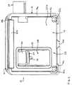
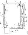
- an accessory module or windshield electronics module 10includes an accessory holding portion or carrier member or support portion 12 that is attachable to a mounting element or attachment member or button 14 attached or secured to an interior surface of a windshield of a vehicle ( FIGS. 1-5 ).
- Accessory module 10includes a housing or casing or cover portion 16 that may attach to carrier portion 12 to substantially encase or contain an accessory within accessory module 10 .
- Carrier portion 12is a unitarily or integrally molded element that receives and/or holds an accessory, such as an imaging sensor 18 ( FIG.
- the accessory moduleis preferably positioned at or near the interior rearview mirror assembly of the vehicle and preferably is positioned at an area of the windshield that is cleaned or wiped by a windshield wiper of the vehicle when the windshield wipers are activated.
- Mounting element or attachment member 14is adhered to or bonded to or otherwise attached or mounted or secured to an interior surface of a windshield of a vehicle.
- mounting element 14is a generally rectangular or square-shaped ring defining a generally planar or flat surface 14 a , which is positioned against the interior surface of the windshield when mounting element 14 is attached to the windshield.
- mounting element 14may include a narrowed portion 14 b along one side and two narrowed portions 14 c at the opposite corners for receiving attaching portions of the carrier portion 12 , such that the attaching portions are positioned between the mounting element 14 and the windshield, as discussed below.
- Mounting element 14may also include another narrowed portion 14 d along a lower side of the mounting element 14 to provide a channel or drain for moisture to exit the accessory module 10 , in the event any moisture or condensation forms within the accessory module.
- the mounting elementmay comprise other shapes or features, or may be other types of elements, such as similar to those described in U.S. patent application Ser. No. 10/355,454, filed Jan. 31, 2003 by Schofield et al. for VEHICLE ACCESSORY MODULE, now U.S. Pat. No. 6,824,281, which is hereby incorporated herein by reference, without affecting the scope of the present invention.
- the mounting elementis thus attachable to the windshield and configured to receive the carrier portion 12 of the accessory module.
- Carrier portion 12includes a base portion 22 that has a surface or face 22 a that generally faces the windshield when carrier portion 12 is attached to mounting element 14 at the windshield.
- base portion 22includes a tab or flange 22 b that is positionable at the narrowed portion 14 b of mounting element 14
- the opposite corners of base portion 22include flexible tabs or snaps or clasps 22 c , which are received at narrowed portions 14 c of mounting element 14 , such that carrier portion 12 may be readily attached or snapped to mounting element 14 when mounting element 14 is attached to the windshield.
- the flexible tabs 22 calso facilitate detachment of carrier portion 12 from the windshield mounting element 14 in case maintenance or replacement of the accessory and/or circuitry is needed.
- Base portion 22may also include one or more guides or flanges 22 d ( FIGS. 6 , 8 and 9 ) that may overlap the lower side and/or lateral sides of the mounting element 14 when positioned at the mounting element 14 to assist in retaining the carrier portion 12 at the mounting element 14 .
- Base portion 22may also include one or more flexible snaps or clasps 22 e extending therefrom (as best shown in FIG. 6 ) for snapping or securing casing or cover portion 16 to carrier portion 12 , as discussed below.
- Carrier portion 12includes an accessory mounting or holding portion 24 that protrudes upward from carrier portion 12 (as shown in FIG. 6 ) for mounting the accessory or accessories of the accessory module.
- Accessory mounting portion 24includes a lens receiving or lens mounting portion 26 for receiving lens 20 .
- Lens mounting portion 26may be threaded so that the lens 20 may be threaded onto lens mounting portion 26 a desired amount.
- the lensmay be otherwise mounted or attached to the lens mounting portion, such as via a snap retention or a retaining ring or the like, without affecting the scope of the present invention.
- Lens mounting portion 26may be positioned within a recess 28 defined by accessory mounting portion 24 so that lens 20 is positioned within the recess and generally at the windshield and directed through the windshield when carrier portion 12 is attached to mounting element 14 at the windshield.
- the lens mounting portion 26may be angled relative to the angle of the base portion 22 of carrier portion 12 to provide the desired angle of the lens 20 relative to the windshield of the vehicle. The angle may be selected to position the lens generally horizontally when the accessory module is attached to the windshield and may vary depending on the angle of the windshield for the particular application of the accessory module.
- accessory, mounting portion 24may define a sensor receiving portion or recess 30 , such as at the rearward end of the lens receiving portion 26 .
- the sensor receiving portion 30is configured to receive imaging sensor 18 therein so that imaging sensor 18 is positioned generally parallel to the plane of the lens 20 (or, in other words, so that the imaging sensor is positioned generally perpendicular to a longitudinal axis of the lens held by the lens receiving portion).
- accessory mounting portion 24defines or provides a generally flat or planar mounting surface 24 a that is spaced from and that may be generally parallel to the sensor receiving portion 30 .
- the imaging sensor 18thus may be provided on a printed circuit board 32 ( FIGS.
- the imaging sensormay comprise an imaging array sensor, such as a CMOS sensor or a CCD sensor or the like, such as described in U.S. Pat. Nos. 5,550,677; 5,670,935; 5,796,094; 6,498,620; 5,877,897; 6,396,397; and 6,313,454, and U.S. patent application Ser. No. 10/421,281, filed Apr. 23, 2003 by Schofield for AUTOMATIC HEADLAMP CONTROL, now U.S. Pat. No. 7,004,606, which are hereby incorporated herein by reference.
- the imaging sensormay comprise a video chip that is mounted on the printed circuit board so that the imaging sensor and circuit board may be provided as a unit from an electronics supplier.
- the lensmay comprise any suitable lens for focusing an image of the exterior scene onto the imaging plane of the imaging sensor.
- the lensmay comprise a lens of the types disclosed in U.S. Pat. Nos. 6,757,109; 6,717,610; 6,590,719; and 6,201,642, which are hereby incorporated herein by reference.
- Imaging sensor 18 and lens 20may be implemented with or incorporated in a forward viewing imaging system, such as an imaging system utilizing the principles disclosed in U.S. Pat. Nos.
- the imaging systemmay function as an automatic headlamp control, such as a headlamp control of the types described in U.S. Pat. Nos. 5,796,094; 5,715,093; 6,742,904; 6,653,615; 6,587,573; 6,831,268; and/or 6,924,470, which are hereby incorporated herein by reference.
- the imaging systemmay also or otherwise function a lane departure warning system, an object detection system, a traffic lane control system, a lane change assist system, a blind spot detection system or an adaptive cruise control system or the like, such as the types described in U.S. Pat. Nos. 5,929,786 and/or 5,786,772; and/or U.S. patent application Ser. No. 10/427,051, filed Apr. 30, 2003 by Pawlieki et al. for OBJECT DETECTION SYSTEM FOR VEHICLE, now U.S. Pat. No. 7,038,577; and/or Ser. No. 10/209,173, filed Jul. 31, 2002 by Schofield for AUTOMOTIVE LANE CHANGE AID, now U.S. Pat.
- the imaging systemmay also or otherwise function as a precipitation sensor or rain sensor, such as the types disclosed in commonly assigned U.S. Pat. Nos. 6,353,392; 6,313,454; and/or 6,320,176, which are hereby incorporated herein by reference.
- the imaging sensormay be optically coupled with or may contact the interior surface of the windshield, or the imaging sensor may be a non-contacting sensor and thus spaced from the interior surface of the windshield, without affecting the scope of the present invention.
- the imaging systemmay also or otherwise function as a traffic sign recognition system (such as the types described in U.S. provisional application Ser. No. 60/562,480, filed Apr. 15, 2004 and U.S. patent application Ser. No. 11/105,757, filed Apr. 14, 2005, now U.S. Pat. No. 7,526,103, which are hereby incorporated herein by reference), or a system for determining a distance to a leading vehicle or object, such as by utilizing the principles disclosed in U.S. Pat. No.
- Carrier portion 12also includes a connector 34 , such as a multi-pin connector or plug or socket, for electrically connecting the accessory module 10 to an electrical wire or cable or lead (not shown) of the vehicle or of the interior rearview mirror assembly of the vehicle or of another accessory module or console or the like of the vehicle.
- the socket portion of connector 34is integrally or unitarily molded with carrier portion 12 and may extend outward from the accessory module 10 when the accessory module is assembled and positioned at the windshield (as shown in FIGS. 1-5 ).
- carrier portion 12may include electrically conducting terminals or pins or elements 36 , which may be insert molded at and partially in and through connector 34 .
- the ends 36 a ( FIGS. 4 and 7 ) of elements 36may be positioned within the socket portion of connector 34 so as to be readily connected to the external wire or cable or lead, while the opposite ends 36 b of elements 36 may extend from connector 34 and may be positioned to engage or insert through circuit board 32 (as shown in FIGS. 7 and 8 ) when circuit board 32 is positioned at mounting surface 24 a of accessory mounting portion 24 .
- FIG. 4 and 7electrically conducting terminals or pins or elements 36
- the ends 36 a ( FIGS. 4 and 7 ) of elements 36may be positioned within the socket portion of connector 34 so as to be readily connected to the external wire or cable or lead, while the opposite ends 36 b of elements 36 may extend from connector 34 and may be positioned to engage or insert through circuit board 32 (as shown in FIGS. 7 and 8 ) when circuit board 32 is positioned at mounting surface
- the connector 34may also define a generally planar mounting surface 34 a against which the circuit board 32 may be positioned to properly orient the circuit board 32 at the desired or appropriate angle or position.
- the carrier portion 12thus provides a unitary molded portion that provides for mounting and positioning of the lens and imaging sensor, and that provides for electrical connection of the circuitry and accessory and/or sensor to an external wire or cable or the like.
- carrier portion 12may also receive or mount a second circuit board 38 , which may include additional accessories or circuitry.
- carrier portion 12may include a pair of stanchions or pillars or mounting posts 40 extending upward from the base portion 22
- accessory mounting portion 24may include a receiving tab 24 b .
- Receiving tab 24 bmay receive an edge or perimeter portion or region of the circuit board 38
- the mounting posts 40may receive an opposite edge or perimeter portion or region of circuit board 38 to retain the circuit board at the carrier portion 12 .
- Mounting posts 40may include flexible tabs or snaps or clasps 40 a to allow for insertion of the circuit board in place at the carrier portion. As can be seen in FIGS.
- the connector 34may include a flange or lip 34 b that is oriented to receive another corner or perimeter portion or region of the circuit board 38 when the circuit board is attached to the carrier portion 12 .
- the connector 34may include additional pins or elements for engaging or inserting through the circuit board 38 when circuit board 38 is mounted to carrier portion 12 , or the circuit board 38 may be electrically connected to the circuit board 32 (such as via a ribbon cable or the like), to electrically connect the circuit board 38 and associate circuitry and accessories to the external wire or cable or the like that is plugged into or otherwise connected to connector 34 .
- the face 22 a of base portion 22is generally at or opposed to the windshield.
- the face 22 apreferably includes a seal or gasket 42 ( FIGS. 1-3 ) around the recess 28 to substantially seal the face 22 a against the windshield around the recess 28 and, thus, around the lens 20 attached to the lens mounting portion 26 .
- accessory mounting portion 24 of carrier portion 12may include an opening or aperture 44 therethrough generally at the lens area and recess 28 .
- the opening 44may allow moisture to leave the lens area and enter into the housing area.
- the carrier portion 12may include a filter or Gore-Tex patch (not shown) or the like (such as the type described in International Publication No. WO 2004/047421 A2, published on Jun. 3, 2004, which is hereby incorporated herein by reference) at the opening 44 to allow only water vapor to pass into the housing area.
- the opening 44thus allows moisture to escape the lens area to avoid moisture that may enter the lens area or recess from condensing at the lens.
- the housing portion 16may be configured to readily attach to or snap onto the carrier portion 12 .
- housing portion 16may include slots or openings 16 a for receiving clasps 22 e of carrier portion 12 to detachably retain housing portion 16 to carrier portion 12 .
- Housing portion 16may also include an opening or slot 16 b ( FIGS. 1 , 4 and 5 ) at one side for receiving connector 34 as housing portion 16 is mounted to carrier portion 12 .
- Carrier portion 12may include another clasp 22 f ( FIGS. 7 and 10 ) for engaging an edge portion of slot 16 b of housing portion 16 to further retain housing portion 16 to carrier portion 12 .
- the present inventionthus provides an accessory module with a unitary accessory holding portion or carrier portion that is configured to receive an accessory, such as an imaging sensor and lens, and associated circuitry, and is configured to electrically connect the circuitry to an external wire or power source or control or the like.
- the circuit board and imaging sensormay be readily attached to the carrier portion, and the lens may be readily mounted and properly positioned at the carrier portion, whereby the carrier portion, with the accessories and circuitry mounted thereon, may be readily attached to the mounting element at the windshield of the vehicle.
- the accessory module of the present inventionthus may be readily assembled and readily mounted at the vehicle with the desired accessories and circuitry for the particular application of the accessory module.
- the imaging sensor and circuit boardmay be provided as a unit and readily attached to the carrier or holding portion of the accessory module, the circuit board manufacturer and/or supplier need not provide the lens as well.
- the lensthen may be provided by a lens manufacturer or supplier, whereby the lens and circuit board/imaging sensor may be received by the accessory module manufacturer or by the vehicle assembler and assembled together.
- the carrier portion of the accessory modulemay be provided at a vehicle assembly plant and different imaging arrays or sensors and/or other accessories or circuit board assemblies may be attached or mounted to the carrier portions depending on the particular application or desired content of the accessory module (such as what types of accessories are provided within or associated with the accessory module).
- the appropriate lensmay be readily attached to the lens mounting portion, whereby the imaging sensor or chip is readily positioned at the appropriate location and orientation relative to the lens, without requiring adjustment of the chip location.
- the lensmay be adjusted (such as via threaded adjustment or the like) to adjust the focus of the lens relative to the imaging sensor, without affecting the scope of the present invention.
- the carrier portionmay be provided for a particular vehicle or vehicle line or windshield angle, so that the lens is properly aligned or oriented with respect to the windshield and vehicle when the accessory module is mounted at the vehicle, in order to define the desired or appropriate viewing direction or field of view of the lens and imaging sensor.
- the accessory modulethus may be provided as a family of modules, with different carrier portions with different angles between the lens mounting portion and the base portion being provided for different vehicles and/or windshield angles, while the same circuit boards and imaging sensors may be provided across different vehicle lines, depending on the desired content and particular application of the accessory module.
- the accessory modulemay include other accessories, such as one or more electrical or electronic devices or accessories, such as antennas, including global positioning system (GPS) or cellular phone antennas, such as the type disclosed in U.S. Pat. No. 5,971,552, a communication module, such as the type disclosed in U.S. Pat. No. 5,798,688, a voice recorder, a digital network, such as the type described in U.S. Pat. No. 5,798,575, transmitters and/or receivers, such as a garage door opener or the like, such as the types described in U.S. patent application Ser. No. 10/770,736, filed Feb. 3, 2004 by Baumgardner et al.
- antennasincluding global positioning system (GPS) or cellular phone antennas, such as the type disclosed in U.S. Pat. No. 5,971,552
- a communication modulesuch as the type disclosed in U.S. Pat. No. 5,798,688, a voice recorder
- a digital networksuch as the type described in U.S. Pat.
- the accessory modulemay provide a storage compartment, such as for storing a hand held garage door opening device or transmitting device or the like), a digital network, such as the type described in U.S. Pat. No. 5,798,575, a memory mirror system, such as the type disclosed in U.S. Pat. No. 5,796,176, a hands-free phone attachment, a video device for internal cabin surveillance and/or video telephone function, such as the types disclosed in U.S. Pat. Nos.
- 6,902,284lights, such as map reading lights or one or more other lights or illumination sources, such as the types disclosed in U.S. Pat. Nos. 5,938,321; 5,813,745; 5,820,245; 5,673,994; 5,649,756; 5,178,448; 5,671,996; 4,646,210; 4,733,336; 4,807,096; 6,690,268; 6,042,253; and/or 5,669,698, and/or U.S. patent application Ser. No. 10/054,633, filed Jan. 22, 2002 by Lynam et al. for VEHICULAR LIGHTING SYSTEM, now U.S. Pat. No.
- microphonessuch as the types disclosed in U.S. Pat. Nos. 6,243,003; 6,278,377; and/or 6,420,975, and/or PCT Application No. PCT/US03/30877, filed Oct. 1, 2003, published Apr. 15, 2004 as International Publication No. WO 2004/032568 A1
- speakersa compass or compass system (which may include the compass sensing circuitry), such as the types disclosed in U.S. Pat. Nos. 5,924,212; 4,862,594; 4,937,945; 5,131,154; 5,255,442; and/or 5,632,092, and/or U.S. patent application Ser. No. 10/456,599, filed Jun.
- a tire pressure monitoring systemsuch as the types disclosed in U.S. Pat. Nos. 6,294,989; 6,445,287; and/or 6,472,979, a seat occupancy detector, a trip computer, a remote starter control, a yaw sensor, a clock, a carbon monoxide detector, status displays, such as displays that display a status of a door of the vehicle, a transmission selection (4wd/2wd or traction control (TCS) or the like), an antilock braking system, a road condition (that may warn the driver of icy road conditions), a telematics system, such as an ONSTAR® system or the like, and/or any other desired accessory or system or the like (with all of the above-referenced patents and patent applications and PCT applications being commonly assigned to Donnelly Corporation, and with the disclosures of all of the above reference
- the accessory or accessoriesmay be positioned at or within the housing and may be included on or integrated in the printed circuit board or boards.
- the housing and accessory modulemay include user inputs or buttons or switches that are accessible by a driver or occupant of the vehicle to control one or more of the accessories of the accessory module and/or of the vehicle.
- the user actuatable inputsmay comprise buttons or switches or touch sensors or proximity sensors or the like.
- connection or link between the controls and the other systems and accessories of the accessory module and/or of the vehiclemay be provided via vehicle electronic or communication systems and the like, and may be connected via various protocols or nodes or wired or wireless communication systems, such as BLUETOOTH®, SCP, UBP, J1850, CAN J2284, Fire Wire 1394, MOST, LIN and/or the like, or other vehicle-based or in-vehicle communication links or systems (such as WIFI and/or IRDA) and/or the like, depending on the particular application of the accessory module or system and the vehicle.
- the connections or linksmay be provided via wireless connectivity or links, without affecting the scope of the present invention.
- the accessory modulemay include a display element, such as a video display element or the like, that may be viewable by a driver or occupant of the vehicle, such as to view vehicle information or captured images, such as images captured by an imaging system of the vehicle.
- the display elementmay slide out or flip up or down from the housing portion to provide a video screen that is viewable by the driver of the vehicle, such as a video display screen of the type described in PCT Application No. PCT/US03/40611, filed Dec. 19, 2003 by Donnelly Corporation for ACCESSORY SYSTEM FOR VEHICLE, published Jul. 15, 2004 as International Publication No. WO 2004/058540 A2, which is hereby incorporated herein by reference.
- the video display screenmay be operable to display information to the driver of the vehicle, and may be incorporated into or may be in communication with a vision system or imaging system of the vehicle, such as a rearwardly directed vehicle vision system utilizing principles disclosed in U.S. Pat. Nos. 5,550,677; 5,760,962; 5,670,935; 6,201,642; 6,717,610; and/or 6,757,109, which are hereby incorporated herein by reference, a trailer hitching aid or tow check system, such as the type disclosed in U.S. patent application Ser. No. 10/418,486, filed Apr. 18, 2003 by McMahon et al. for VEHICLE IMAGING SYSTEM, now U.S. Pat. No.
- a cabin viewing device or systemsuch as a baby viewing or rear seat viewing camera or device or system or the like, such as disclosed in U.S. Pat. Nos. 5,877,897 and 6,690,268, which are hereby incorporated herein by reference
- a video communication device or systemsuch as disclosed in U.S. Pat. No. 6,690,268, which is hereby incorporated herein by reference, and/or the like.
- the video display screenmay also or otherwise serve as a screen for a navigation system of the vehicle or the like, such as a GPS-based navigation system, such as is known in the automotive art.
- the accessory modulemay include or may be associated with a telematics system of the vehicle, such as an ONSTAR® system as found in General Motors vehicles or the like, and/or such as described in U.S. Pat. Nos. 4,862,594; 4,937,945; 5,131,154; 5,255,442; 5,632,092; 5,798,688; 5,971,552; 5,924,212; 6,243,003; 6,278,377; and 6,420,975; 6,477,464; and/or 6,678,614; and/or U.S. patent application Ser. No. 10/456,599, filed Jun. 6, 2003 by Weller et al.
- the accessory modulemay be positioned at or near an interior rearview mirror assembly of the vehicle, and/or one or more of the accessories or circuitry of the accessory module may be associated with one or more accessories or controls of the interior rearview mirror assembly.
- the accessory modulemay be positioned at or near a prismatic mirror assembly, such as a prismatic mirror assembly utilizing aspects described in U.S. Pat. Nos. 6,318,870; 5,327,288; 4,948,242; 4,826,289; 4,436,371; and 4,435,042, and PCT Application No. PCT/US2004/015424, filed May 18, 2004 by Donnelly Corporation et al. for MIRROR ASSEMBLY FOR VEHICLE, published Dec. 2, 2004 as International Publication No.
- the prismatic reflective elementmay comprise a conventional prismatic reflective element or prism or may comprise a prismatic reflective element of the types described in PCT Application No. PCT/US03/29776, filed Sep. 19, 2003 by Donnelly Corp. et al. for MIRROR REFLECTIVE ELEMENT ASSEMBLY, published Apr. 1, 2004 as International Publication No. WO 2004/026633 A2; U.S. patent application Ser. No. 10/709,434, filed May 5, 2004 by Lynam for MIRROR REFLECTIVE ELEMENT, now U.S. Pat. No. 7,420,756, and Ser. No. 10/993,302, filed Nov.
- the interior rearview mirror assemblymay comprise an electro-optic or electrochromic mirror assembly, which may utilize some of the principles described in commonly assigned U.S. Pat. Nos. 6,690,268; 5,140,455; 5,151,816; 6,178,034; 6,154,306; 6,002,544; 5,567,360; 5,525,264; 5,610,756; 5,406,414; 5,253,109; 5,076,673; 5,073,012; 5,117,346; 5,724,187; 5,668,663; 5,910,854; 5,142,407 and/or 4,712,879, which are hereby incorporated herein by reference, and/or as described in the following publications: N. R.
- Lynam“Electrochromic Automotive Day/Night Mirrors”, SAE Technical Paper Series 870636 (1987); N. R. Lynam, “Smart Windows for Automobiles”, SAE Technical Paper Series 900419 (1990); N. R. Lynam and A. Agrawal, “Automotive Applications of Chromogenic Materials”, Large Area Chromogenics: Materials and Devices for Transmittance Control , C. M. Lampert and C. G. Granquist, EDS., Optical Engineering Press, Wash. (1990), which are hereby incorporated by reference herein; and/or as described in U.S. patent application Ser. No. 10/054,633, filed Jan. 22, 2002 by Lynam et al.
- the mirror assemblymay include one or more displays, such as the types disclosed in U.S. Pat. Nos. 5,530,240 and/or 6,329,925, which are hereby incorporated herein by reference, and/or display-on-demand transflective type displays, such as the types disclosed in U.S. Pat. Nos. 6,690,268; 5,668,663 and/or 5,724,187, and/or in U.S. patent application Ser. No. 10/054,633, filed Jan. 22, 2002 by Lynam et al. for VEHICULAR LIGHTING SYSTEM, now U.S. Pat. No.
- the interior rearview mirror assemblymay be mounted at the accessory module, such as via a button-on-button mounting arrangement or the like, or the accessory module may constitute a base or mounting portion of the mirror assembly, or the accessory module and mirror assembly may be otherwise attached to or connected to or associated with one another, without affecting the scope of the present invention.
- the accessory module and/or mirror assemblymay include a control system for controlling the dimming of the electro-optic mirror reflective element or cell, such as for controlling an electrochromic mirror reflective element or cell, such as a control system of the types described in U.S. Pat. Nos. 6,406,152; 6,305,807; 6,291,905; 6,089,721; 6,056,410; and/or 6,210,008, which are hereby incorporated herein by reference.
- the control systemmay be included or incorporated in the mirror casing of the mirror assembly (or in any other part of the mirror assembly, such as a mounting portion or a pod portion or the like), and may include or, and preferably, may be substantially established on an application specific integrated chip (ASIC), such as an ASIC positioned at or to the rear of the mirror reflective element of the interior mirror assembly.
- ASICapplication specific integrated chip
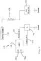
- the EC driver circuitis operable to control the electro-optic or electrochromic (EC) mirror reflective element or cell (by adjusting or controlling the voltage applied to the powering electrode at the conductive coatings of the mirror reflective element or cell) in response to an ignition voltage and a current gating element or transistor. For example, and as shown in FIG.
- an interior electro optic mirror control system 110 for controlling an interior electro-optic or electrochromic mirror reflective element or cell 112includes control circuitry or a microprocessor or the like on a circuit board or controller 114 (such as an EC-driver-circuit-on-a-chip, such as established at or on an ASIC or “chip”) and a current gating element 116 .
- the control system 110 and mirror reflective elementis preferably powered by an ignition voltage 118 of the vehicle (or other power source), which preferably is directly connected via a resistor 122 to a powering electrode of the EC cell to power the EC cell 112 (with the other side or electrode of the EC cell being grounded or connected to ground).
- a voltage sensing line 120is connected between the powering electrode of the EC cell 112 and the ASIC controller 114 , whereby the ASIC controller can determine/measure the voltage being applied at any moment in time to the EC cell.
- the ASIC controllerthus can sense or monitor the voltage and control the voltage applied across the EC cell (via control of the current flow through current gating element 116 ) so that it does not exceed its tolerable design intent (typically between 0 to 1.4 volts DC or thereabouts).
- Current flowing through current gating element 116is controlled by ASIC controller 114 via control line 124 .
- the current gating element 116 and the EC cell 112are grounded or connected to or in conductive communication with ground. Note that this is a preferred embodiment, but other embodiments are contemplated utilizing further electronic or electrical circuitry or components.
- ASIC controller 114When the ASIC controller 114 detects that the voltage (as sensed by sense line 120 ) being applied across the EC cell is higher than what is desired or can be tolerated by the electrochromic medium utilized in the EC cell, then ASIC controller 114 opens up current flow through current gating element 116 to maintain the desired applied tolerable voltage across the EC cell. Further, should it be desired to further reduce an applied voltage across the EC cell, then ASIC controller 114 may further open up or increase current flow through the current gating element 116 so that voltage across the EC cell is reduced. Thus, in order to bleach the cell (i.e.
- the control line 124essentially reduces the resistive path through the current gating element 116 close to or at about zero ohms.
- the ASIC controllerthus detects the instantaneous voltage (as dropped from the vehicle ignition through resistor 122 and supplied to the powering electrode of the EC cell), and may adjust or control or open the gating element 116 to shunt a desired or appropriate amount of current through the gating element to ground, such that a reduced or desired or appropriate voltage is applied to the EC cell to maintain the voltage at the EC cell within the tolerable range and/or to achieve the desired degree of dimming of the electro-optic mirror reflective element or cell.
- the ASIC controllerresponds to detected glaring and ambient light levels about the vehicle to increase or decrease the resistance path through gating element 116 to increase or decrease the voltage across the EC cell, as needed or appropriate for the particular glaring or ambient lighting conditions encountered while driving at night, while always ensuring that the EC cell is not damaged or endangered by an over-voltage such as might occur should an ignition voltage or close to an ignition voltage be applied for more than a momentary period across the EC medium.
- the ASIC controllerincludes photosensors 126 a , 126 b , such as photodiodes or phototransistors or the like, for sensing glare and ambient light at the mirror assembly.
- one or more of the photosensorsmay be in communication with a light pipe for piping or conduiting ambient light or glare light from external to the mirror assembly to the photosensor or photosensors within the casing and at the ASIC controller.
- the light pipe or pipesmay utilize aspects of the light-piping described in U.S. patent application Ser. No. 10/229,573, filed Aug. 28, 2002 by Blank for VEHICLE MIRROR SYSTEM WITH LIGHT CONDUITING MEMBER, and published Mar. 6, 2003 as Publication No. U.S.
- the light pipe connected to or in communication with the ambient light sensing photosensormay be routed generally downwardly from the photosensor to receive ambient light from a lower portion view port of the mirror casing of the mirror assembly (or could be routed upward to an upper portion view port of the mirror casing).
- the circuitry or ASIC controllerthus may determine the glare and ambient light present at the mirror assembly in response to the outputs of the photosensors and may adjust or control the current gating element so that the appropriate degree of dimming is achieved at the mirror reflective element or cell.
- the initial voltagee.g. about 12 volts
- the ASIC controllerwill then control the current gating element to shunt the appropriate amount of voltage/current through the current gating element to reduce the voltage at the mirror cell to a desired and tolerable voltage level (such as a voltage typically between zero volts and about 1.4 volts or thereabouts).
- the ASIC controllerdetects or determines (such as in response to the outputs of the ambient light and glare photosensors) that the cell should be dimmed a greater or reduced amount (such as via a detection of reduced glare and/or increased ambient light)
- the ASIC controlleradjusts or controls or opens/closes the current gating element (via the control line) to shunt a desired or appropriate amount of the current/voltage to ground so that an increased/reduced amount of current/voltage is applied to the mirror reflective element or cell, thereby dimming the cell an increased/reduced/desired amount.
- the circuitry or circuit board or ASIC controller 114may include various processing elements established on a chip, such as a microprocessor, memory, an A/D converter, a D/A converter, a LIN/CAN BUS, an EC cell voltage sensing/control, a dawn/dusk shutdown circuitry, timers, drivers, and/or the like.
- the ASIC controllermay include compass sensors and/or circuitry and/or the like, such as in a similar manner as a “compass-on-a-chip”, such as described in U.S. patent application Ser. No. 11/021,065, filed Dec. 23, 2004 by McCabe et al. for ELECTRO-OPTIC MIRROR CELL, now U.S. Pat. No.
- the ASIC controllermay be positioned within the mirror casing, such as at and behind the mirror reflective element or cell.
- the current gating element or transistor 116may be internal to or incorporated in the ASIC controller, or may be external to the ASIC controller, without affecting the scope of the present invention.
- the control system or ASIC controllermay have one, two or three current gating elements or transistors or the like (such as for control channels for only one mirror reflective element or for two or three mirror reflective elements, such as for an interior mirror reflective element and two outside or exterior mirror reflective elements), with any one or all of which may be internal or external to the ASIC controller, without affecting the scope of the present invention.
- Control circuitryand software and hardware to so do, are known in the art.
- ASICstypically include a microprocessor, such as an eight bit or sixteen bit MCU, UART, memory, such as 8K ROM or more, memory, such as 256 bytes RAM, ADC, WPG, timers, A/D converters, D/A converters, display drivers, thermistors, LIN or CAN communication I/Os, other I/Os, high-side drivers and half-bridge drivers, all established on a silicon or similar semiconductor substrate.
- suchcan be adapted to form the EC-driver-on-a-chip by co-establishing on the semiconductor substrate two photosensitive areas, such as by forming photodiodes or phototransistors on the substrate.
- lensing and/or infrared light filteringmay be provided at the chip level in such an EC-driver-on-a-chip.
- the ignition voltage 118may be unregulated and may provide an output of about 9 volts to about 16 volts typical, and about 12.8 volts nominal.
- the resistor 122may comprise any type of suitable resistor, and may provide a resistance of about 20 ohms to about 40 ohms or thereabouts, with about two to five watts of power dissipation or greater or lower depending on the particular EC interior mirror construction.
- the resistormay comprise a copper or PTC trace on a flexible circuit or pad attached to the rear of the mirror reflective element or cell, or may comprise any other suitable resistor element, without affecting the scope of the present invention.
- the interior rearview mirror elementitself can function as a heat sink to the likes of a flat ribbon power dropping resistor attached thereto.
- the EC-driver-on-a-chipcould be implemented for an independent exterior rearview mirror, such as by utilizing aspects described in U.S. Pat. No. 5,659,423, which is hereby incorporated herein by reference.
- Such use of large-scale integration of electronic functionality/circuitry in an EC-driver-on-a-chipcan achieve a markedly lower package size at a reduced cost than has hitherto been known for EC driver circuitry, and can allow greater design and construction flexibility for the interior mirror assembly.
- an interior rearview mirror assembly 210may be wirelessly powered and controlled via a remote or wireless communication link or system 212 and a remote or wireless power link or system 214 .
- Mirror assembly 210includes a mirror casing or housing 216 and a reflective element 218 .
- Mirror assembly 210also includes one or more electrically powered accessories 220 , such as power consuming accessories within the mirror casing 216 , such as at or established on a printed circuit board or ASIC controller or the like within the mirror assembly. Because the mirror accessories are powered and controlled by wireless systems, the mirror assembly may include power consuming accessories without the additional requirement of wires and/or cables extending between the mirror assembly and the headliner of the vehicle.
- the wireless power link or system 214includes a remotely located inductive power transmitter 222 , such as positioned in or at the headliner 224 of the vehicle, and an inductive power receiver or transceiver 226 , such as positioned at or in the mirror casing 216 of mirror assembly 210 .
- the transmittercan be located elsewhere in the vehicle, such as within an instrument panel region, or in a side door/side panel portion when inductively coupling to an exterior mirror assembly or an exterior door handle assembly.
- the inductive power transmitter 222comprises a power coil located in the headliner of the vehicle (and connected to a power source of the vehicle, such as via wires or cables), while the inductive power receiver 226 comprises a receiver coil in or at the mirror assembly for receiving the inductive power generated by the power coil.
- the remote power systemthus provides inductive power coupling to the mirror assembly from a location remote from the mirror assembly, without wires or cables connected between the remote location and mirror assembly.
- the inductive power system of the present inventionmay utilize aspects of the inductive powered devices described in U.S. Pat. Nos. 6,917,163; 6,825,620; 6,812,645; 6,731,071; and 5,264,997, which are hereby incorporated herein by reference.
- the frequencies and protocols and means used for operation of the inductive power link or systemmay be selected to reduce or minimize adverse effects the inductive power coupling may have on the wireless communication system and on the performance of the accessories at or in or near the mirror assembly or elsewhere in the vehicle, and can be chosen to minimize/eliminate any EMI/RFI impact on vehicle electricals.
- any electrical/electronic components or accessories of the mirror assembly(such as for example, a map or a reading lamp or an electrochromic mirror reflective element or a garage door opener or a compass circuit or a camera or a headlamp controller or a heater pad or a motor or the like) is provided by inductive coupling rather than by wired connection.
- the secondary (receiving) element (typically a coil) of the inductively powered linkis preferably placed such as in the mirror housing or elsewhere in the mirror assembly (or in a windshield accessory module), and in proximity (typically a few inches up to about ten inches or so) to and adjacent to but separated from and remote from the primary (transmitting) element (that also typically is a coil) of the inductive coupling system that is connected to the vehicle battery/ignition power supply in order to supply power to the inductively powered mirror or accessory module assembly via a wireless link.
- the elimination of electrical connectorsmay enhance the reliability of the system by eliminating the costs and complexities associated with conventional electrical connectors.
- the wireless communication link or system 212includes a data transceiver 228 , such as located at or in the headliner, and a data transceiver 230 , such as at or in the mirror assembly.
- the wireless communication systemthus provides for wireless communication between the data transceiver 228 and the data transceiver 230 to communicate with and/or control the accessories 220 of the mirror assembly.
- a broadband or multi-channel wireless communication linkcan be established allowing multiple inputs and outputs to the mirror assembly and control of and data I/O to and from a plurality of controls and devices within and at the interior mirror assembly.
- the wireless communication link or data channelmay comprise various wireless links or protocols, such as an infrared communication link (such as described in U.S. patent application Ser. No.
- the mirror assembly 210includes a double ball mounting arrangement 232 (although other mounting arrangements, such as single ball mounting arrangements or the like may be implemented without affecting the scope of the present invention), which pivotally mounts the mirror casing 216 and reflective element 218 to a mounting base or channel mount 234 , which, in turn, is attached to a mounting button or attachment element 236 at the interior surface of the windshield 238 of the vehicle.
- the mirror assembly and mounting basethus may be mounted to the windshield at a location spaced downward from the headliner of the vehicle, without requiring any wires or cables or wire covers or the like along the windshield and between the mounting base and the headliner.
- the reflective element of the mirror assemblymay comprise an electro-optic reflective element (such as an electrochromic reflective element) or a prismatic reflective element, without affecting the scope of the present invention.
- the power receivermay be located elsewhere, such as within the mirror casing, or at or in or near a pod or module or windshield electronics module (WEM) or at or in an exterior mirror or the like, without affecting the scope of the present invention.
- the remote or wireless power systemthus provides power to the power receiver and to the accessories at or near or connected to or associated with the power receiver to power the accessories, while the wireless communication system provides communication and/or control to and from the accessories at or near or connected to or associated with the power receiver to control or activate/deactivate or monitor the accessories.
- the mirror systemdoes not require or include a wire harness and connector and wire cover or the like that is typically positioned along the windshield of the vehicle and between the mirror mount and the headliner of the vehicle. Also, because no such wires and wire covers are located along the windshield, the desire or need of a frit layer or the like at the windshield to conceal such wires/wire covers is obviated.
- the interior mirror assemblies and/or accessory modules of the present inventionmay include a hard disc drive (HDD) electronic mass storage device, and preferably a HDD microdrive, such as a one-inch (or smaller) HDD, such as are developed by Hitachi Global Storage Technologies, Inc. (HGST) of the United States, Hoya Corp. of Japan, and Seagate Technology LLC.
- HDDhard disc drive
- HGSTHitachi Global Storage Technologies, Inc.
- the accessory modulemay be at or near or associated with another accessory module or windshield electronics module or console or other types of modules or housings, such as the types described in U.S. patent application Ser. No. 10/355,454, filed Jan. 31, 2003 by Schofield et al. for VEHICLE ACCESSORY MODULE, now U.S. Pat. No. 6,824,281; and Ser. No. 10/456,599, filed Jun. 6, 2003 by Weller et al. for INTERIOR REARVIEW MIRROR SYSTEM WITH COMPASS, now U.S. Pat. No. 7,004,593, and/or U.S. Pat. Nos.
- the accessory module and/or mirror assemblymay utilize aspects of the modules and mirror assemblies described in U.S. provisional applications, Ser. No. 60/692,113, filed Jun. 20, 2005; Ser. No. 60/677,990, filed May 5, 2005; Ser. No. 60/653,787, filed Feb. 17, 2005; Ser. No. 60/642,227, filed Jan.
- the present inventionprovides an accessory module that may include an imaging sensor or device and may include other accessories as well.
- the accessory moduleincludes a unitarily molded support or carrier portion that readily receives the accessory and circuitry to ease assembly of the accessory module.
- the assembled carrier portion, with the accessory or accessories and associated circuitry mounted thereon,may be readily attached to a mounting element or button at the windshield of the vehicle.
- the imaging sensor and lensare oriented at the desired angle to provide the desired or appropriate field of view through the windshield of the vehicle. Because the carrier portion of the accessory module is unitarily formed, there are fewer components, which eases the assembly of the accessory module and deproliferates parts in the assembly plant.
Landscapes
- Engineering & Computer Science (AREA)
- Mechanical Engineering (AREA)
- Multimedia (AREA)
- Physics & Mathematics (AREA)
- Automation & Control Theory (AREA)
- Mathematical Physics (AREA)
- Transportation (AREA)
- Signal Processing (AREA)
- General Physics & Mathematics (AREA)
- Theoretical Computer Science (AREA)
- Fittings On The Vehicle Exterior For Carrying Loads, And Devices For Holding Or Mounting Articles (AREA)
Abstract
Description
Claims (27)
Priority Applications (5)
| Application Number | Priority Date | Filing Date | Title |
|---|---|---|---|
| US12/354,339US7719408B2 (en) | 2000-03-02 | 2009-01-15 | Mirror system for vehicle |
| US12/753,433US8531278B2 (en) | 2000-03-02 | 2010-04-02 | Accessory system for vehicle |
| US14/021,474US8710969B2 (en) | 2004-08-18 | 2013-09-09 | Accessory system for vehicle |
| US14/263,074US9266474B2 (en) | 2004-08-18 | 2014-04-28 | Accessory system for vehicle |
| US15/049,570US10773724B2 (en) | 2004-08-18 | 2016-02-22 | Accessory system for vehicle |
Applications Claiming Priority (31)
| Application Number | Priority Date | Filing Date | Title |
|---|---|---|---|
| US18652000P | 2000-03-02 | 2000-03-02 | |
| US18796000P | 2000-03-09 | 2000-03-09 | |
| US21833600P | 2000-07-14 | 2000-07-14 | |
| US23441200P | 2000-09-21 | 2000-09-21 | |
| US23707700P | 2000-09-30 | 2000-09-30 | |
| US23848300P | 2000-10-06 | 2000-10-06 | |
| US24398600P | 2000-10-27 | 2000-10-27 | |
| US26368001P | 2001-01-23 | 2001-01-23 | |
| US27146601P | 2001-02-26 | 2001-02-26 | |
| US09/793,002US6690268B2 (en) | 2000-03-02 | 2001-02-26 | Video mirror systems incorporating an accessory module |
| US09/799,414US6477464B2 (en) | 2000-03-09 | 2001-03-05 | Complete mirror-based global-positioning system (GPS) navigation solution |
| US31538401P | 2001-08-28 | 2001-08-28 | |
| US34673302P | 2002-01-07 | 2002-01-07 | |
| US10/054,633US7195381B2 (en) | 2001-01-23 | 2002-01-22 | Vehicle interior LED lighting system |
| US40490602P | 2002-08-21 | 2002-08-21 | |
| US40539202P | 2002-08-23 | 2002-08-23 | |
| US40616602P | 2002-08-27 | 2002-08-27 | |
| US10/287,178US6678614B2 (en) | 1999-11-24 | 2002-11-04 | Navigation system for a vehicle |
| US10/456,599US7004593B2 (en) | 2002-06-06 | 2003-06-06 | Interior rearview mirror system with compass |
| US10/645,762US7167796B2 (en) | 2000-03-09 | 2003-08-20 | Vehicle navigation system for use with a telematics system |
| US10/755,915US7446650B2 (en) | 1998-01-07 | 2004-01-13 | Accessory system suitable for use in a vehicle |
| US52212304P | 2004-08-18 | 2004-08-18 | |
| US11/201,661US7480149B2 (en) | 2004-08-18 | 2005-08-11 | Accessory module for vehicle |
| US11/623,997US7344284B2 (en) | 2001-01-23 | 2007-01-17 | Lighting system for a vehicle, with high-intensity power LED |
| US11/624,381US7490007B2 (en) | 2000-03-02 | 2007-01-18 | Video mirror system for a vehicle |
| US11/625,374US7579939B2 (en) | 1998-01-07 | 2007-01-22 | Video mirror system suitable for use in a vehicle |
| US11/935,800US7571042B2 (en) | 2000-03-02 | 2007-11-06 | Navigation system for a vehicle |
| US12/043,567US7731403B2 (en) | 2001-01-23 | 2008-03-06 | Lighting system for a vehicle, with high-intensity power LED |
| US12/052,341US7579940B2 (en) | 1998-01-07 | 2008-03-20 | Information display system for a vehicle |
| US12/061,372US7619508B2 (en) | 2001-01-23 | 2008-04-02 | Video mirror system for a vehicle |
| US12/354,339US7719408B2 (en) | 2000-03-02 | 2009-01-15 | Mirror system for vehicle |
Related Parent Applications (3)
| Application Number | Title | Priority Date | Filing Date |
|---|---|---|---|
| US11/201,661ContinuationUS7480149B2 (en) | 2000-03-02 | 2005-08-11 | Accessory module for vehicle |
| US12/052,341Continuation-In-PartUS7579940B2 (en) | 1998-01-07 | 2008-03-20 | Information display system for a vehicle |
| US12/061,372Continuation-In-PartUS7619508B2 (en) | 2000-03-02 | 2008-04-02 | Video mirror system for a vehicle |
Related Child Applications (1)
| Application Number | Title | Priority Date | Filing Date |
|---|---|---|---|
| US12/753,433DivisionUS8531278B2 (en) | 2000-03-02 | 2010-04-02 | Accessory system for vehicle |
Publications (2)
| Publication Number | Publication Date |
|---|---|
| US20090122430A1 US20090122430A1 (en) | 2009-05-14 |
| US7719408B2true US7719408B2 (en) | 2010-05-18 |
Family
ID=35909100
Family Applications (6)
| Application Number | Title | Priority Date | Filing Date |
|---|---|---|---|
| US11/201,661Active2026-11-29US7480149B2 (en) | 2000-03-02 | 2005-08-11 | Accessory module for vehicle |
| US12/354,339Expired - Fee RelatedUS7719408B2 (en) | 2000-03-02 | 2009-01-15 | Mirror system for vehicle |
| US12/753,433Expired - Fee RelatedUS8531278B2 (en) | 2000-03-02 | 2010-04-02 | Accessory system for vehicle |
| US14/021,474Expired - LifetimeUS8710969B2 (en) | 2004-08-18 | 2013-09-09 | Accessory system for vehicle |
| US14/263,074Active2026-02-28US9266474B2 (en) | 2004-08-18 | 2014-04-28 | Accessory system for vehicle |
| US15/049,570Expired - Fee RelatedUS10773724B2 (en) | 2004-08-18 | 2016-02-22 | Accessory system for vehicle |
Family Applications Before (1)
| Application Number | Title | Priority Date | Filing Date |
|---|---|---|---|
| US11/201,661Active2026-11-29US7480149B2 (en) | 2000-03-02 | 2005-08-11 | Accessory module for vehicle |
Family Applications After (4)
| Application Number | Title | Priority Date | Filing Date |
|---|---|---|---|
| US12/753,433Expired - Fee RelatedUS8531278B2 (en) | 2000-03-02 | 2010-04-02 | Accessory system for vehicle |
| US14/021,474Expired - LifetimeUS8710969B2 (en) | 2004-08-18 | 2013-09-09 | Accessory system for vehicle |
| US14/263,074Active2026-02-28US9266474B2 (en) | 2004-08-18 | 2014-04-28 | Accessory system for vehicle |
| US15/049,570Expired - Fee RelatedUS10773724B2 (en) | 2004-08-18 | 2016-02-22 | Accessory system for vehicle |
Country Status (1)
| Country | Link |
|---|---|
| US (6) | US7480149B2 (en) |
Cited By (58)
| Publication number | Priority date | Publication date | Assignee | Title |
|---|---|---|---|---|
| US20100007805A1 (en)* | 2008-07-11 | 2010-01-14 | Vitito Christopher J | Inductively powered mobile entertainment system |
| US20100208077A1 (en)* | 2000-03-02 | 2010-08-19 | Donnelly Corporation | Accessory system for vehicle |
| US8481916B2 (en) | 1998-01-07 | 2013-07-09 | Magna Electronics Inc. | Accessory mounting system for a vehicle having a light absorbing layer with a light transmitting portion for viewing through from an accessory |
| US8508593B1 (en) | 2002-01-31 | 2013-08-13 | Magna Electronics | Vehicle accessory system |
| US8513590B2 (en) | 1998-01-07 | 2013-08-20 | Magna Electronics Inc. | Vehicular accessory system with a cluster of sensors on or near an in-cabin surface of the vehicle windshield |
| US8531279B2 (en) | 1999-08-25 | 2013-09-10 | Magna Electronics Inc. | Accessory mounting system for a vehicle |
| US8534887B2 (en) | 1997-08-25 | 2013-09-17 | Magna Electronics Inc. | Interior rearview mirror assembly for a vehicle |
| US8570374B2 (en) | 2008-11-13 | 2013-10-29 | Magna Electronics Inc. | Camera for vehicle |
| US8686840B2 (en) | 2000-03-31 | 2014-04-01 | Magna Electronics Inc. | Accessory system for a vehicle |
| US8692659B2 (en) | 1998-01-07 | 2014-04-08 | Magna Electronics Inc. | Accessory mounting system for vehicle |
| USD710278S1 (en) | 2011-05-20 | 2014-08-05 | Wade Hanlon | Decorative cover for a side view mirror |
| US8879139B2 (en) | 2012-04-24 | 2014-11-04 | Gentex Corporation | Display mirror assembly |
| US8964024B2 (en) | 2012-08-02 | 2015-02-24 | Gentex Corporation | System and method for controlling exterior vehicle lights responsive to detection of a semi-truck |
| US8977439B2 (en) | 2012-06-12 | 2015-03-10 | Genetex Corporation | Vehicle imaging system providing multi-stage aiming stability indication |
| US8983135B2 (en) | 2012-06-01 | 2015-03-17 | Gentex Corporation | System and method for controlling vehicle equipment responsive to a multi-stage village detection |
| US9090213B2 (en) | 2004-12-15 | 2015-07-28 | Magna Electronics Inc. | Accessory mounting system for a vehicle |
| US9171217B2 (en) | 2002-05-03 | 2015-10-27 | Magna Electronics Inc. | Vision system for vehicle |
| US9187029B2 (en) | 2013-10-01 | 2015-11-17 | Gentex Corporation | System and method for controlling exterior vehicle lights on motorways |
| US9191634B2 (en) | 2004-04-15 | 2015-11-17 | Magna Electronics Inc. | Vision system for vehicle |
| US9233645B2 (en) | 1999-11-04 | 2016-01-12 | Magna Electronics Inc. | Accessory mounting system for a vehicle |
| US9317758B2 (en) | 2013-08-19 | 2016-04-19 | Gentex Corporation | Vehicle imaging system and method for distinguishing reflective objects from lights of another vehicle |
| US9434314B2 (en) | 1998-04-08 | 2016-09-06 | Donnelly Corporation | Electronic accessory system for a vehicle |
| US9436880B2 (en) | 1999-08-12 | 2016-09-06 | Magna Electronics Inc. | Vehicle vision system |
| US9434327B2 (en) | 2013-11-15 | 2016-09-06 | Gentex Corporation | Imaging system including dynamic compensation for color attenuation for vehicle windscreens |
| US9440535B2 (en) | 2006-08-11 | 2016-09-13 | Magna Electronics Inc. | Vision system for vehicle |
| US9511715B2 (en) | 2014-01-31 | 2016-12-06 | Gentex Corporation | Backlighting assembly for display for reducing cross-hatching |
| US9575315B2 (en) | 2013-09-24 | 2017-02-21 | Gentex Corporation | Display mirror assembly |
| USD783480S1 (en) | 2014-12-05 | 2017-04-11 | Gentex Corporation | Rearview device |
| US9619720B2 (en) | 2013-08-19 | 2017-04-11 | Gentex Corporation | Vehicle imaging system and method for distinguishing between vehicle tail lights and flashing red stop lights |
| US9694752B2 (en) | 2014-11-07 | 2017-07-04 | Gentex Corporation | Full display mirror actuator |
| US9694751B2 (en) | 2014-09-19 | 2017-07-04 | Gentex Corporation | Rearview assembly |
| US9720278B2 (en) | 2015-01-22 | 2017-08-01 | Gentex Corporation | Low cost optical film stack |
| US9744907B2 (en) | 2014-12-29 | 2017-08-29 | Gentex Corporation | Vehicle vision system having adjustable displayed field of view |
| USD797627S1 (en) | 2015-10-30 | 2017-09-19 | Gentex Corporation | Rearview mirror device |
| USD798207S1 (en) | 2015-10-30 | 2017-09-26 | Gentex Corporation | Rearview mirror assembly |
| USD800618S1 (en) | 2015-11-02 | 2017-10-24 | Gentex Corporation | Toggle paddle for a rear view device |
| US9834146B2 (en) | 2014-04-01 | 2017-12-05 | Gentex Corporation | Automatic display mirror assembly |
| USD809984S1 (en) | 2016-12-07 | 2018-02-13 | Gentex Corporation | Rearview assembly |
| USD817238S1 (en) | 2016-04-29 | 2018-05-08 | Gentex Corporation | Rearview device |
| US9995854B2 (en) | 2015-04-20 | 2018-06-12 | Gentex Corporation | Rearview assembly with applique |
| US9994156B2 (en) | 2015-10-30 | 2018-06-12 | Gentex Corporation | Rearview device |
| US10025138B2 (en) | 2016-06-06 | 2018-07-17 | Gentex Corporation | Illuminating display with light gathering structure |
| US10071689B2 (en) | 2014-11-13 | 2018-09-11 | Gentex Corporation | Rearview mirror system with a display |
| US10099629B2 (en)* | 2016-09-06 | 2018-10-16 | Huf North America Automotive Parts Manufacturing Corp. | Deployable sensor assembly |
| US10112540B2 (en) | 2015-05-18 | 2018-10-30 | Gentex Corporation | Full display rearview device |
| US10131279B2 (en) | 2014-12-03 | 2018-11-20 | Gentex Corporation | Display mirror assembly with an RF shield bezel |
| US10207646B2 (en)* | 2015-02-10 | 2019-02-19 | Lg Electronics Inc. | Vehicle front camera module integrated with rearview mirror |
| USD845851S1 (en) | 2016-03-31 | 2019-04-16 | Gentex Corporation | Rearview device |
| USD854473S1 (en) | 2016-12-16 | 2019-07-23 | Gentex Corporation | Rearview assembly |
| US10371931B2 (en)* | 2013-03-14 | 2019-08-06 | Sony Corporation | Digital microscope apparatus, method of searching for in-focus position thereof, and program |
| US10468914B2 (en) | 2013-03-11 | 2019-11-05 | Robert Bosch Gmbh | Contactless power transfer system |
| US10685623B2 (en) | 2015-10-30 | 2020-06-16 | Gentex Corporation | Toggle paddle |
| US10705332B2 (en) | 2014-03-21 | 2020-07-07 | Gentex Corporation | Tri-modal display mirror assembly |
| US10735638B2 (en) | 2017-03-17 | 2020-08-04 | Gentex Corporation | Dual display reverse camera system |
| US11178353B2 (en) | 2015-06-22 | 2021-11-16 | Gentex Corporation | System and method for processing streamed video images to correct for flicker of amplitude-modulated lights |
| US11800050B2 (en) | 2016-12-30 | 2023-10-24 | Gentex Corporation | Full display mirror with on-demand spotter view |
| US11838611B1 (en) | 2021-06-11 | 2023-12-05 | T-Mobile Usa, Inc. | Vehicle display device with simulated mirror and wireless connectivity |
| US11994272B2 (en) | 2021-08-20 | 2024-05-28 | Gentex Corporation | Lighting assembly and illumination system having a lighting assembly |
Families Citing this family (213)
| Publication number | Priority date | Publication date | Assignee | Title |
|---|---|---|---|---|
| US5877897A (en) | 1993-02-26 | 1999-03-02 | Donnelly Corporation | Automatic rearview mirror, vehicle lighting control and vehicle interior monitoring system using a photosensor array |
| US5910854A (en) | 1993-02-26 | 1999-06-08 | Donnelly Corporation | Electrochromic polymeric solid films, manufacturing electrochromic devices using such solid films, and processes for making such solid films and devices |
| US5668663A (en) | 1994-05-05 | 1997-09-16 | Donnelly Corporation | Electrochromic mirrors and devices |
| US6891563B2 (en) | 1996-05-22 | 2005-05-10 | Donnelly Corporation | Vehicular vision system |
| US7655894B2 (en) | 1996-03-25 | 2010-02-02 | Donnelly Corporation | Vehicular image sensing system |
| US6172613B1 (en) | 1998-02-18 | 2001-01-09 | Donnelly Corporation | Rearview mirror assembly incorporating vehicle information display |
| US8294975B2 (en) | 1997-08-25 | 2012-10-23 | Donnelly Corporation | Automotive rearview mirror assembly |
| US6329925B1 (en)* | 1999-11-24 | 2001-12-11 | Donnelly Corporation | Rearview mirror assembly with added feature modular display |
| US6477464B2 (en) | 2000-03-09 | 2002-11-05 | Donnelly Corporation | Complete mirror-based global-positioning system (GPS) navigation solution |
| US6693517B2 (en) | 2000-04-21 | 2004-02-17 | Donnelly Corporation | Vehicle mirror assembly communicating wirelessly with vehicle accessories and occupants |
| US7167796B2 (en) | 2000-03-09 | 2007-01-23 | Donnelly Corporation | Vehicle navigation system for use with a telematics system |
| US7004593B2 (en) | 2002-06-06 | 2006-02-28 | Donnelly Corporation | Interior rearview mirror system with compass |
| US7370983B2 (en) | 2000-03-02 | 2008-05-13 | Donnelly Corporation | Interior mirror assembly with display |
| US7581859B2 (en)* | 2005-09-14 | 2009-09-01 | Donnelly Corp. | Display device for exterior rearview mirror |
| ES2287266T3 (en) | 2001-01-23 | 2007-12-16 | Donnelly Corporation | IMPROVED VEHICLE LIGHTING SYSTEM. |
| WO2006124682A2 (en) | 2005-05-16 | 2006-11-23 | Donnelly Corporation | Vehicle mirror assembly with indicia at reflective element |
| US7255451B2 (en) | 2002-09-20 | 2007-08-14 | Donnelly Corporation | Electro-optic mirror cell |
| US6918674B2 (en)* | 2002-05-03 | 2005-07-19 | Donnelly Corporation | Vehicle rearview mirror system |
| US7329013B2 (en) | 2002-06-06 | 2008-02-12 | Donnelly Corporation | Interior rearview mirror system with compass |
| US20060061008A1 (en) | 2004-09-14 | 2006-03-23 | Lee Karner | Mounting assembly for vehicle interior mirror |
| US10144353B2 (en) | 2002-08-21 | 2018-12-04 | Magna Electronics Inc. | Multi-camera vision system for a vehicle |
| US7310177B2 (en) | 2002-09-20 | 2007-12-18 | Donnelly Corporation | Electro-optic reflective element assembly |
| EP1543358A2 (en) | 2002-09-20 | 2005-06-22 | Donnelly Corporation | Mirror reflective element assembly |
| WO2004047421A2 (en) | 2002-11-14 | 2004-06-03 | Donnelly Corporation | Imaging system for vehicle |
| DE60316346T2 (en)* | 2002-12-20 | 2008-06-05 | Donnelly Corp., Holland | AID SYSTEM FOR VEHICLES |
| US7446924B2 (en) | 2003-10-02 | 2008-11-04 | Donnelly Corporation | Mirror reflective element assembly including electronic component |
| US7308341B2 (en) | 2003-10-14 | 2007-12-11 | Donnelly Corporation | Vehicle communication system |
| US7510287B2 (en)* | 2005-10-21 | 2009-03-31 | Donnelly Corporation | Wire cover assembly for vehicle interior mirror |
| CN101816008A (en)* | 2005-10-28 | 2010-08-25 | 马格纳电子系统公司 | Camera module for vehicle vision system |
| EP1949666B1 (en) | 2005-11-01 | 2013-07-17 | Magna Mirrors of America, Inc. | Interior rearview mirror with display |
| EP2122599B1 (en)* | 2007-01-25 | 2019-11-13 | Magna Electronics Inc. | Radar sensing system for vehicle |
| US7948352B2 (en)* | 2007-10-08 | 2011-05-24 | Abb Research Ltd. | Wirelessly powered secondary electrical distribution equipment |
| US9324230B2 (en)* | 2008-12-04 | 2016-04-26 | Gentex Corporation | System and method for configuring a wireless control system of a vehicle using induction field communication |
| US8154418B2 (en) | 2008-03-31 | 2012-04-10 | Magna Mirrors Of America, Inc. | Interior rearview mirror system |
| US20100085653A1 (en)* | 2008-09-15 | 2010-04-08 | Magna Mirrors Of America, Inc. | Mirror assembly for vehicle |
| US8482664B2 (en) | 2008-10-16 | 2013-07-09 | Magna Electronics Inc. | Compact camera and cable system for vehicular applications |
| US9487144B2 (en) | 2008-10-16 | 2016-11-08 | Magna Mirrors Of America, Inc. | Interior mirror assembly with display |
| DE102009005571A1 (en)* | 2009-01-21 | 2010-07-22 | Adc Automotive Distance Control Systems Gmbh | Retrofittable driver assistance system |
| EP2394426A4 (en) | 2009-02-06 | 2013-02-20 | Magna Electronics Inc | IMPROVEMENTS IN A VEHICLE CAMERA |
| EP2401176B1 (en) | 2009-02-27 | 2019-05-08 | Magna Electronics | Alert system for vehicle |
| US8451332B2 (en) | 2009-03-23 | 2013-05-28 | Magna Mirrors Of America, Inc. | Interior mirror assembly with adjustable mounting assembly |
| US12328491B1 (en) | 2009-03-25 | 2025-06-10 | Magna Electronics Inc. | Vehicular camera and lens assembly |
| EP3438721B1 (en) | 2009-03-25 | 2020-07-08 | Magna Electronics Inc. | Vehicular camera and lens assembly |
| US20100284154A1 (en)* | 2009-04-09 | 2010-11-11 | Scl Elements Inc. | Modular sensor mote |
| US8376595B2 (en) | 2009-05-15 | 2013-02-19 | Magna Electronics, Inc. | Automatic headlamp control |
| WO2012051500A1 (en) | 2010-10-15 | 2012-04-19 | Magna Mirrors Of America, Inc. | Interior rearview mirror assembly |
| US9649995B2 (en)* | 2009-10-13 | 2017-05-16 | Munster Simms Engineering Limited | Utilities pod for caravans |
| US8851690B2 (en)* | 2009-10-27 | 2014-10-07 | Magna Mirrors Of America, Inc. | Mounting assembly for vehicle interior mirror |
| US10303035B2 (en) | 2009-12-22 | 2019-05-28 | View, Inc. | Self-contained EC IGU |
| US8213074B1 (en) | 2011-03-16 | 2012-07-03 | Soladigm, Inc. | Onboard controller for multistate windows |
| US11342791B2 (en) | 2009-12-22 | 2022-05-24 | View, Inc. | Wirelessly powered and powering electrochromic windows |
| JP5805658B2 (en)* | 2009-12-22 | 2015-11-04 | ビュー, インコーポレイテッド | Electrochromic window powered wirelessly |
| US11732527B2 (en) | 2009-12-22 | 2023-08-22 | View, Inc. | Wirelessly powered and powering electrochromic windows |
| US8339453B2 (en)* | 2010-07-14 | 2012-12-25 | Trw Automotive U.S. Llc | Apparatus for use in association with a vehicle |
| US20120235474A1 (en)* | 2010-09-14 | 2012-09-20 | Joseph Mannino | Windshield embedded power coil for wireless charging |
| US9180908B2 (en) | 2010-11-19 | 2015-11-10 | Magna Electronics Inc. | Lane keeping system and lane centering system |
| JP5472078B2 (en)* | 2010-12-21 | 2014-04-16 | 株式会社デンソー | Car camera |
| JP5316562B2 (en)* | 2011-02-10 | 2013-10-16 | 株式会社デンソー | Car camera |
| US8897633B2 (en) | 2010-12-21 | 2014-11-25 | Denso Corporation | In-vehicle camera unit having camera built into body |
| US10046716B2 (en)* | 2011-02-10 | 2018-08-14 | Denso Corporation | In-vehicle camera and vehicle control system |
| US9194943B2 (en) | 2011-04-12 | 2015-11-24 | Magna Electronics Inc. | Step filter for estimating distance in a time-of-flight ranging system |
| US9380219B2 (en)* | 2011-04-20 | 2016-06-28 | Magna Electronics Inc. | Angular filter for vehicle mounted cameras |
| US9547795B2 (en) | 2011-04-25 | 2017-01-17 | Magna Electronics Inc. | Image processing method for detecting objects using relative motion |
| JP5632967B2 (en)* | 2011-05-24 | 2014-11-26 | 本田技研工業株式会社 | Vehicle mounted camera |
| TWM428395U (en)* | 2011-05-30 | 2012-05-01 | Acard Technology Corp | Expanding grip for tablet PC |
| DE102011106957A1 (en)* | 2011-07-08 | 2013-01-10 | Gm Global Technology Operations, Llc | Vehicle with at least one camera, in particular reversing camera |
| US9596387B2 (en) | 2011-08-02 | 2017-03-14 | Magna Electronics Inc. | Vehicular camera system |
| US9487159B2 (en) | 2011-08-02 | 2016-11-08 | Magna Electronics Inc. | Vehicle vision system with camera module mounting bracket |
| US9871971B2 (en) | 2011-08-02 | 2018-01-16 | Magma Electronics Inc. | Vehicle vision system with light baffling system |
| US20140218535A1 (en) | 2011-09-21 | 2014-08-07 | Magna Electronics Inc. | Vehicle vision system using image data transmission and power supply via a coaxial cable |
| WO2013056064A1 (en)* | 2011-10-14 | 2013-04-18 | Continental Automotive Systems, Inc | Integrated rear camera display |
| US10071687B2 (en) | 2011-11-28 | 2018-09-11 | Magna Electronics Inc. | Vision system for vehicle |
| US8694224B2 (en) | 2012-03-01 | 2014-04-08 | Magna Electronics Inc. | Vehicle yaw rate correction |
| JP5853795B2 (en)* | 2012-03-19 | 2016-02-09 | 株式会社デンソー | Car camera |
| US10089537B2 (en) | 2012-05-18 | 2018-10-02 | Magna Electronics Inc. | Vehicle vision system with front and rear camera integration |
| US9340227B2 (en) | 2012-08-14 | 2016-05-17 | Magna Electronics Inc. | Vehicle lane keep assist system |
| DE102013217430A1 (en) | 2012-09-04 | 2014-03-06 | Magna Electronics, Inc. | Driver assistance system for a motor vehicle |
| US9244249B2 (en)* | 2012-09-28 | 2016-01-26 | Gentex Corporation | Double ball slide on mount with screw over sensor |
| US9352691B2 (en) | 2012-11-05 | 2016-05-31 | Magna Mirrors Of America, Inc. | Interior rearview mirror assembly |
| US9090234B2 (en) | 2012-11-19 | 2015-07-28 | Magna Electronics Inc. | Braking control system for vehicle |
| US9092986B2 (en) | 2013-02-04 | 2015-07-28 | Magna Electronics Inc. | Vehicular vision system |
| US10027930B2 (en) | 2013-03-29 | 2018-07-17 | Magna Electronics Inc. | Spectral filtering for vehicular driver assistance systems |
| US9327693B2 (en) | 2013-04-10 | 2016-05-03 | Magna Electronics Inc. | Rear collision avoidance system for vehicle |
| US20140313337A1 (en)* | 2013-04-23 | 2014-10-23 | Magna Electronics Inc. | Vehicle vision system with fastenerless lens attachment |
| US9280202B2 (en) | 2013-05-10 | 2016-03-08 | Magna Electronics Inc. | Vehicle vision system |
| US20140340770A1 (en)* | 2013-05-15 | 2014-11-20 | Thomas John Barniak, JR. | Lens assembly for the motor vehicle; a driver's aid for enhaned visibility while driving |
| US9260095B2 (en) | 2013-06-19 | 2016-02-16 | Magna Electronics Inc. | Vehicle vision system with collision mitigation |
| US20140375476A1 (en) | 2013-06-24 | 2014-12-25 | Magna Electronics Inc. | Vehicle alert system |
| US9487161B2 (en)* | 2013-10-04 | 2016-11-08 | Magna Mirrors Of America, Inc. | Accessory system for a vehicle |
| US9451138B2 (en) | 2013-11-07 | 2016-09-20 | Magna Electronics Inc. | Camera for vehicle vision system |
| US9499139B2 (en) | 2013-12-05 | 2016-11-22 | Magna Electronics Inc. | Vehicle monitoring system |
| US9988047B2 (en) | 2013-12-12 | 2018-06-05 | Magna Electronics Inc. | Vehicle control system with traffic driving control |
| DE102013021518A1 (en)* | 2013-12-12 | 2015-06-18 | Connaught Electronics Ltd. | Electronic device with an improved bearing for a connection unit, camera system for a motor vehicle and motor vehicle |
| USD722931S1 (en)* | 2013-12-20 | 2015-02-24 | Michael A. Giordano | Accessory rear view mirror mount |
| USD722932S1 (en)* | 2013-12-20 | 2015-02-24 | Michael A. Giordano | Accessory rear view mirror mount |
| US10017114B2 (en) | 2014-02-19 | 2018-07-10 | Magna Electronics Inc. | Vehicle vision system with display |
| US9352692B2 (en) | 2014-03-10 | 2016-05-31 | Magna Mirrors Of America, Inc. | Vehicle vision system with camera and mirror mount |
| US9749509B2 (en) | 2014-03-13 | 2017-08-29 | Magna Electronics Inc. | Camera with lens for vehicle vision system |
| JP2015193366A (en)* | 2014-03-17 | 2015-11-05 | 日本電産エレシス株式会社 | Manufacturing method of box body for on-vehicle camera, box body for on-vehicle camera, and on-vehicle camera |
| US9587942B2 (en) | 2014-04-01 | 2017-03-07 | Magna Mirrors Of America, Inc. | Vehicle compass system with heated windshield compensation |
| US9896039B2 (en) | 2014-05-09 | 2018-02-20 | Magna Electronics Inc. | Vehicle vision system with forward viewing camera |
| US10389016B2 (en) | 2014-05-12 | 2019-08-20 | Magna Electronics Inc. | Vehicle communication system with heated antenna |
| US10967796B2 (en) | 2014-05-15 | 2021-04-06 | Magna Mirrors Of America, Inc. | Interior rearview mirror assembly with low profile mirror |
| US11634078B2 (en) | 2014-05-15 | 2023-04-25 | Magna Mirrors Of America, Inc. | Vehicular rearview mirror control system |
| CN106458107A (en)* | 2014-06-11 | 2017-02-22 | Trw汽车美国有限责任公司 | Moderation of a driver assist camera environment by headliner air duct |
| US9621769B2 (en) | 2014-06-11 | 2017-04-11 | Magna Electronics Inc. | Camera module for vehicle vision system |
| US9819211B2 (en) | 2014-06-26 | 2017-11-14 | Nissan North America, Inc. | Wireless charging assembly for a vehicle |
| USD772299S1 (en)* | 2014-06-27 | 2016-11-22 | Denso Corporation | Automotive engine computer unit cover |
| US11114742B2 (en) | 2014-11-25 | 2021-09-07 | View, Inc. | Window antennas |
| DE102014018687A1 (en) | 2014-12-18 | 2016-06-23 | Huf Hülsbeck & Fürst Gmbh & Co. Kg | Module unit for a motor vehicle |
| DE102014018686A1 (en)* | 2014-12-18 | 2016-06-23 | Huf Hülsbeck & Fürst Gmbh & Co. Kg | Module unit for a motor vehicle |
| JP6172174B2 (en)* | 2015-02-06 | 2017-08-02 | トヨタ自動車株式会社 | Vehicle front information acquisition device |
| US9764744B2 (en) | 2015-02-25 | 2017-09-19 | Magna Electronics Inc. | Vehicle yaw rate estimation system |
| JP6197812B2 (en)* | 2015-03-05 | 2017-09-20 | トヨタ自動車株式会社 | In-vehicle camera mounting structure |
| US10112552B2 (en) | 2015-03-11 | 2018-10-30 | Magna Electronics Inc. | Vehicle vision system with camera viewing through windshield |
| CN107431785A (en)* | 2015-03-12 | 2017-12-01 | Trw汽车美国有限责任公司 | A kind of low gloss housing unit for driver assistance system image pick-up device |
| US10023118B2 (en) | 2015-03-23 | 2018-07-17 | Magna Electronics Inc. | Vehicle vision system with thermal sensor |
| US9777756B2 (en) | 2015-04-27 | 2017-10-03 | Taylor Made Group, Llc | Glass edge snap attachment |
| US10819943B2 (en)* | 2015-05-07 | 2020-10-27 | Magna Electronics Inc. | Vehicle vision system with incident recording function |
| US10000156B2 (en) | 2015-06-02 | 2018-06-19 | Magna Mirrors Of America, Inc. | Vehicle mirror mount assembly |
| US9994152B1 (en)* | 2015-08-07 | 2018-06-12 | Ryan Hess | Active scanning collision avoidance system |
| KR102487620B1 (en) | 2015-09-15 | 2023-01-12 | 엘지이노텍 주식회사 | Thin film type heater for camera module and camera module having the same |
| US10137904B2 (en) | 2015-10-14 | 2018-11-27 | Magna Electronics Inc. | Driver assistance system with sensor offset correction |
| US10875403B2 (en) | 2015-10-27 | 2020-12-29 | Magna Electronics Inc. | Vehicle vision system with enhanced night vision |
| US9986136B2 (en) | 2015-10-30 | 2018-05-29 | Magna Electronics Inc. | Vehicle camera with single point imager fixation to lens holder |
| US9881501B2 (en) | 2015-11-02 | 2018-01-30 | Magna Electronics Inc. | Driver assistance system with traffic light alert |
| US10560613B2 (en) | 2015-11-05 | 2020-02-11 | Magna Electronics Inc. | Vehicle camera with modular construction |
| US10351072B2 (en) | 2015-11-05 | 2019-07-16 | Magna Electronics Inc. | Vehicle camera with modular construction |
| US10230875B2 (en) | 2016-04-14 | 2019-03-12 | Magna Electronics Inc. | Camera for vehicle vision system |
| US10250004B2 (en) | 2015-11-05 | 2019-04-02 | Magna Electronics Inc. | Method of forming a connector for an electrical cable for electrically connecting to a camera of a vehicle |
| JP6141468B1 (en)* | 2016-02-05 | 2017-06-07 | 三菱電機株式会社 | Car camera |
| US10132971B2 (en) | 2016-03-04 | 2018-11-20 | Magna Electronics Inc. | Vehicle camera with multiple spectral filters |
| US10055651B2 (en) | 2016-03-08 | 2018-08-21 | Magna Electronics Inc. | Vehicle vision system with enhanced lane tracking |
| JP6408505B2 (en)* | 2016-03-24 | 2018-10-17 | 本田技研工業株式会社 | Sensor bracket |
| JP6510999B2 (en)* | 2016-03-24 | 2019-05-08 | 本田技研工業株式会社 | Sensor bracket |
| US10142532B2 (en) | 2016-04-08 | 2018-11-27 | Magna Electronics Inc. | Camera for vehicle vision system |
| US12140849B2 (en) | 2016-05-02 | 2024-11-12 | Magna Mirrors Of America, Inc. | Multifunctional rearward viewing camera system |
| US10948798B2 (en) | 2016-05-02 | 2021-03-16 | Magna Mirrors Of America, Inc. | Caseless rearview mirror assembly |
| US10647266B2 (en) | 2016-05-17 | 2020-05-12 | Magna Electronics Inc. | Vehicle vision system with forward viewing camera |
| JP6767186B2 (en)* | 2016-07-20 | 2020-10-14 | 日野自動車株式会社 | In-vehicle camera device |
| US10373731B1 (en)* | 2016-08-09 | 2019-08-06 | Apple Inc. | Systems with hidden signal paths |
| US10237456B2 (en) | 2016-08-22 | 2019-03-19 | Magna Electronics Inc. | Vehicle camera assembly process |
| US11568773B2 (en)* | 2016-09-16 | 2023-01-31 | James Calvin Stanley | Displaying device |
| US11150448B2 (en)* | 2016-11-06 | 2021-10-19 | Denso Corporation | Vehicle windshield mounted camera module |
| JP6504145B2 (en)* | 2016-11-24 | 2019-04-24 | 株式会社Jvcケンウッド | Vehicle recording device |
| US10894275B2 (en) | 2017-01-20 | 2021-01-19 | Magna Electronics Inc. | Vehicle camera with lens heater and washer system |
| FR3066160B1 (en)* | 2017-05-11 | 2020-11-06 | Saint Gobain | VEHICLE WINDOWS INCLUDING AN ACCESSORY MOUNTING BASE WITH METAL PIECE AND ACCESSORY MOUNTING BASE. |
| US10652437B2 (en) | 2017-05-19 | 2020-05-12 | Magna Electronics Inc. | Vehicle camera with aluminum extruded body |
| US10232799B2 (en) | 2017-07-19 | 2019-03-19 | Ford Global Technologies, Llc | Cameras and camera housings for vehicle trailers |
| US10239469B2 (en) | 2017-07-19 | 2019-03-26 | Ford Global Technologies, Llc | Cameras and camera housings for vehicle trailers |
| US10752175B2 (en) | 2017-08-07 | 2020-08-25 | Magna Mirrors Of America, Inc. | Pivot mounting assembly for interior rearview mirror |
| US10527910B2 (en)* | 2017-08-29 | 2020-01-07 | Trw Automotive U.S. Llc | Vehicle driver assist system |
| US10761319B2 (en) | 2017-10-13 | 2020-09-01 | Magna Electronics Inc. | Vehicle camera with lens heater |
| US10855890B2 (en) | 2017-10-23 | 2020-12-01 | Magna Electronics Inc. | Camera for vehicle vision system with enhanced heat removal |
| US10682966B2 (en) | 2017-11-16 | 2020-06-16 | Magna Electronics Inc. | Vehicle light/display control system using camera |
| TWM563372U (en)* | 2018-02-01 | 2018-07-11 | 雄鉅實業有限公司 | Electronic device with L-shaped fastening device |
| WO2019172364A1 (en)* | 2018-03-07 | 2019-09-12 | 株式会社小糸製作所 | Cleaner-equipped sensor system for vehicle |
| US10924685B2 (en)* | 2018-05-07 | 2021-02-16 | Rubicon Products, LLC | Night vision apparatus |
| US10640043B2 (en) | 2018-05-08 | 2020-05-05 | Magna Electronics Inc. | Vehicular rain sensing system using forward viewing camera |
| US10899275B2 (en) | 2018-06-27 | 2021-01-26 | Magna Electronics Inc. | Vehicular camera with PCB focus tuning |
| US10676041B2 (en) | 2018-07-06 | 2020-06-09 | Magna Electronics Inc. | Vehicular camera with pliable connection of PCBS |
| EP3821356B1 (en)* | 2018-07-12 | 2022-08-31 | Gentex Corporation | Mirror assembly incorporating a scanning apparatus |
| JP7151234B2 (en) | 2018-07-19 | 2022-10-12 | 株式会社デンソー | Camera system and event recording system |
| US11124130B2 (en) | 2018-08-01 | 2021-09-21 | Magna Electronics Inc. | Vehicular forward viewing camera |
| FR3086768B1 (en)* | 2018-09-27 | 2020-09-18 | Valeo Systemes Dessuyage | PROTECTION DEVICE FOR AN OPTICAL SENSOR OF A DRIVING ASSISTANCE SYSTEM FOR MOTOR VEHICLES |
| US10957023B2 (en) | 2018-10-05 | 2021-03-23 | Magna Electronics Inc. | Vehicular vision system with reduced windshield blackout opening |
| US11683911B2 (en) | 2018-10-26 | 2023-06-20 | Magna Electronics Inc. | Vehicular sensing device with cooling feature |
| US10911647B2 (en) | 2018-11-12 | 2021-02-02 | Magna Electronics Inc. | Vehicular camera with thermal compensating means |
| US12120408B2 (en) | 2019-01-28 | 2024-10-15 | Magna Electronics Inc. | Vehicular forward camera module with cooling fan and air duct |
| US11290622B2 (en) | 2019-01-28 | 2022-03-29 | Magna Electronics Inc. | Vehicular forward camera module with integrated cooling fan |
| US11140301B2 (en) | 2019-02-26 | 2021-10-05 | Magna Mirrors Of America, Inc. | Vehicular camera with lens/cover cleaning feature |
| US11082630B2 (en) | 2019-03-13 | 2021-08-03 | Magna Electronics Inc. | Vehicular vision system using adaptive mask at camera |
| US11205083B2 (en) | 2019-04-02 | 2021-12-21 | Magna Electronics Inc. | Vehicular driver monitoring system |
| US11199758B2 (en) | 2019-08-05 | 2021-12-14 | Magna Electronics Inc. | Vehicular camera assembly process with dual focusing feature |
| US12371027B2 (en) | 2019-08-23 | 2025-07-29 | Magna Electronics Inc. | Vehicular driving assist system with traffic jam probability determination |
| US11938795B2 (en) | 2019-10-18 | 2024-03-26 | Magna Electronics Inc. | Vehicular vision system with glare reducing windshield |
| US12184830B2 (en) | 2019-11-01 | 2024-12-31 | Magna Electronics Inc. | Vehicular camera testing system using spring-loaded electrical connectors |
| US12036990B2 (en) | 2019-11-22 | 2024-07-16 | Magna Electronics Inc. | Vehicular control system with controlled vehicle stopping and starting at intersection |
| US11816905B2 (en) | 2020-03-19 | 2023-11-14 | Magna Electronics Inc. | Multi-camera vision system integrated into interior rearview mirror |
| DE102021203783B4 (en) | 2020-04-17 | 2022-04-28 | Magna Mirrors Of America, Inc. | INTERNAL REARVIEW MIRROR ARRANGEMENT WITH DRIVER MONITORING SYSTEM |
| US12174448B2 (en) | 2020-06-08 | 2024-12-24 | Magna Electronics Inc. | Vehicular camera assembly process using welding to secure lens relative to camera image plane |
| US11635672B2 (en) | 2020-06-08 | 2023-04-25 | Magna Electronics Inc. | Vehicular camera assembly process using welding to secure lens relative to camera image plane |
| US11823395B2 (en) | 2020-07-02 | 2023-11-21 | Magna Electronics Inc. | Vehicular vision system with road contour detection feature |
| US11724707B2 (en) | 2020-07-08 | 2023-08-15 | Magna Electronics Inc. | Vehicular control system with automatic stack clearing of stack frame |
| US11750905B2 (en)* | 2020-08-14 | 2023-09-05 | Magna Electronics Inc. | Vehicular camera with inductive lens heater |
| US12337894B2 (en) | 2020-08-17 | 2025-06-24 | Magna Electronics Inc. | Vehicular control system with traffic jam assist |
| US11801795B2 (en) | 2020-09-18 | 2023-10-31 | Magna Electronics Inc. | Vehicular camera with lens heater with connectors |
| US11997371B2 (en) | 2021-01-22 | 2024-05-28 | Magna Electronics Inc. | Vehicular cooling system for forward camera module |
| US11851080B2 (en) | 2021-02-03 | 2023-12-26 | Magna Mirrors Of America, Inc. | Vehicular driver monitoring system with posture detection and alert |
| US11972597B2 (en) | 2021-02-09 | 2024-04-30 | Magna Electronics Inc. | Vehicular driver monitoring system with camera view optimization |
| US11889171B2 (en) | 2021-02-15 | 2024-01-30 | Magna Mirrors Of America, Inc. | Vehicular camera with lens/cover cleaning feature |
| US11780372B2 (en) | 2021-03-01 | 2023-10-10 | Magna Mirrors Of America, Inc. | Vehicular driver monitoring system with driver monitoring camera and near IR light emitter at interior rearview mirror assembly |
| US11639134B1 (en) | 2021-03-01 | 2023-05-02 | Magna Mirrors Of America, Inc. | Interior rearview mirror assembly with driver monitoring system |
| US12022176B2 (en) | 2021-05-06 | 2024-06-25 | Magna Electronics Inc. | Vehicular exterior camera with lens attached to imager circuit board |
| US12110015B2 (en) | 2021-05-11 | 2024-10-08 | Magna Electronics Inc. | Vehicular driving assistance system with lateral motion control |
| US11766968B2 (en) | 2021-05-18 | 2023-09-26 | Magna Mirrors Of America, Inc. | Vehicular interior rearview mirror assembly with video mirror display and VRLC stack |
| US11930264B2 (en) | 2021-05-18 | 2024-03-12 | Magna Electronics Inc. | Vehicular driver monitoring system with camera view optimization |
| US12316940B2 (en) | 2021-05-19 | 2025-05-27 | Magna Electronics Inc. | Vehicular camera assembly process using laser etching for active focusing after lens is secured relative to imager |
| JP7650723B2 (en)* | 2021-05-21 | 2025-03-25 | 小島プレス工業株式会社 | Heater fixing structure for vehicle-mounted camera |
| DE102021205284A1 (en)* | 2021-05-25 | 2022-12-01 | Zf Friedrichshafen Ag | Housing for electronic components and control unit |
| US12071150B2 (en) | 2021-06-25 | 2024-08-27 | Magna Electronics Inc. | Vehicular driving assist system using forward viewing camera |
| CN113581091B (en)* | 2021-07-09 | 2023-09-08 | 江西省玉上佳科技有限公司 | Vehicle-mounted external multifunctional intelligent camera |
| US12311930B2 (en) | 2021-07-09 | 2025-05-27 | Magna Electronics Inc. | Vehicular driving assistance system with enhanced traffic lane determination |
| CN117940316B (en) | 2021-09-03 | 2024-12-06 | 马格纳电子系统公司 | Vehicle interior monitoring system having an optical transmitter selectively operated for DMS and OMS functions |
| US12145513B2 (en) | 2021-10-11 | 2024-11-19 | Magna Electronics Inc. | Vehicular windshield-mounted forward camera vision system |
| US12208739B2 (en) | 2022-01-13 | 2025-01-28 | Magna Electronics Inc. | Vehicular camera assembly process with enhanced attachment of imager assembly at camera housing |
| US12258025B2 (en) | 2022-02-01 | 2025-03-25 | Magna Electronics Inc. | Vehicular driver monitoring system with event camera |
| US12333770B2 (en) | 2022-05-13 | 2025-06-17 | Magna Electronics Inc. | Vehicular camera with polarization filter |
| US11833972B1 (en) | 2022-05-13 | 2023-12-05 | Magna Mirrors Holding Gmbh | Vehicle overhead console with cooling fan |
| US12134358B2 (en) | 2022-05-16 | 2024-11-05 | Magna Mirrors Of America, Inc. | Vehicular driver monitoring system |
| US12422691B2 (en) | 2022-05-17 | 2025-09-23 | Magna Electronics Inc. | Vehicular camera assembly with lens barrel welded at imager housing |
| DE102023212939A1 (en) | 2023-01-01 | 2024-07-04 | Magna Mirrors Of America, Inc. | SYSTEM FOR MONITORING A DRIVER OF A VEHICLE |
| US12213261B2 (en)* | 2023-06-27 | 2025-01-28 | GM Global Technology Operations LLC | Protective enclosure for an electronic device |
Citations (76)
| Publication number | Priority date | Publication date | Assignee | Title |
|---|---|---|---|---|
| US4286305A (en) | 1979-04-10 | 1981-08-25 | Pilat Eugene R | Electronic security device and method |
| DE3605704A1 (en) | 1986-02-21 | 1987-08-27 | Siemens Ag | Adaptor for the additional fastening of special devices to the mount of an inside rear view mirror in a vehicle |
| US4760497A (en) | 1987-05-18 | 1988-07-26 | Roston Stewart A | Bracket mount for automobile radar detector unit |
| US4768135A (en) | 1986-01-18 | 1988-08-30 | Robert Bosch Gmbh | Headlight arrangement for vehicles |
| US4781436A (en) | 1986-03-14 | 1988-11-01 | Armbruster Joseph M | Illuminated feather-touch solenoid actuated vehicle day/night mirror |
| US4793690A (en) | 1986-07-18 | 1988-12-27 | Donnelly Corporation | Rearview mirror control circuit |
| US4891559A (en) | 1985-06-13 | 1990-01-02 | Nippondenso Soken, Inc. | Apparatus for controlling a headlight of a vehicle |
| US4930742A (en) | 1988-03-25 | 1990-06-05 | Donnelly Corporation | Rearview mirror and accessory mount for vehicles |
| US4967319A (en) | 1988-05-02 | 1990-10-30 | Nissan Motor Co., Ltd. | Headlight apparatus for automotive vehicle |
| US5193029A (en) | 1991-11-19 | 1993-03-09 | Donnelly Corporation | Single sensor adaptive drive circuit for rearview mirror system |
| US5255442A (en) | 1991-12-20 | 1993-10-26 | Donnelly Corporation | Vehicle compass with electronic sensor |
| US5264997A (en) | 1992-03-04 | 1993-11-23 | Dominion Automotive Industries Corp. | Sealed, inductively powered lamp assembly |
| US5330149A (en) | 1993-01-28 | 1994-07-19 | Donnelly Corporation | Breakaway accessory mounting for vehicles |
| US5377949A (en) | 1993-02-25 | 1995-01-03 | Donnelly Corporation | Breakaway accessory mounting for vehicles |
| US5426294A (en) | 1992-05-27 | 1995-06-20 | Koito Manufacturing Co., Ltd. | Glare sensor for a vehicle |
| US5455716A (en) | 1990-08-14 | 1995-10-03 | Prince Corporation | Vehicle mirror with electrical accessories |
| US5487522A (en) | 1993-11-30 | 1996-01-30 | Donnelly Corporation | Mirror support bracket |
| US5537003A (en) | 1994-04-08 | 1996-07-16 | Gentex Corporation | Control system for automotive vehicle headlamps and other vehicle equipment |
| US5550677A (en) | 1993-02-26 | 1996-08-27 | Donnelly Corporation | Automatic rearview mirror system using a photosensor array |
| US5576687A (en) | 1991-12-20 | 1996-11-19 | Donnelly Corporation | Vehicle information display |
| US5587236A (en) | 1991-10-09 | 1996-12-24 | Donnelly Corporation | Interior rear view mirror mounting system utilizing one-package structural adhesive |
| US5631638A (en) | 1993-07-09 | 1997-05-20 | Hohe Gmbh & Co.Kg. | Information system in a motor vehicle |
| US5659423A (en) | 1994-09-30 | 1997-08-19 | Donnelly Corporation | Modular variable reflectance mirror assembly |
| US5660454A (en) | 1992-08-28 | 1997-08-26 | Toyota Jidosha Kabushiki Kaisha | Apparatus and method for controlling light distribution of headlamp |
| US5708743A (en) | 1993-02-23 | 1998-01-13 | The Whitaker Corporation | Light bending devices |
| US5796176A (en) | 1996-07-11 | 1998-08-18 | Donnelly Corporation | Memory mirror system for vehicles |
| US5796094A (en) | 1993-02-26 | 1998-08-18 | Donnelly Corporation | Vehicle headlight control using imaging sensor |
| US5820097A (en) | 1997-01-10 | 1998-10-13 | Donnelly Corporation | Breakaway accessory mounting assembly for vehicles and windshield mounted button therefor |
| US5845000A (en) | 1992-05-05 | 1998-12-01 | Automotive Technologies International, Inc. | Optical identification and monitoring system using pattern recognition for use with vehicles |
| US5940503A (en) | 1993-02-02 | 1999-08-17 | Palett; Anthony P. | Mirror mounted mobile telephone system |
| US5971552A (en) | 1995-12-08 | 1999-10-26 | Donnelly Corporation | Vehicle global positioning system |
| US6056410A (en) | 1997-04-02 | 2000-05-02 | Donnelly Corporation | Digital electrochromic mirror system |
| US6087953A (en) | 1998-02-18 | 2000-07-11 | Donnelly Corporation | Rearview mirror support incorporating vehicle information display |
| US6089721A (en) | 1997-04-02 | 2000-07-18 | Donnelly Corporation | Digital electrochromic mirror system |
| US6124886A (en) | 1997-08-25 | 2000-09-26 | Donnelly Corporation | Modular rearview mirror assembly |
| US6151065A (en) | 1995-06-20 | 2000-11-21 | Steed; Van P. | Concealed integrated vehicular camera safety system |
| US6158655A (en) | 1998-04-08 | 2000-12-12 | Donnelly Corporation | Vehicle mounted remote transaction interface system |
| US6166698A (en) | 1999-02-16 | 2000-12-26 | Gentex Corporation | Rearview mirror with integrated microwave receiver |
| US6166625A (en) | 1996-09-26 | 2000-12-26 | Donnelly Corporation | Pyroelectric intrusion detection in motor vehicles |
| US6172613B1 (en) | 1998-02-18 | 2001-01-09 | Donnelly Corporation | Rearview mirror assembly incorporating vehicle information display |
| US6229434B1 (en) | 1999-03-04 | 2001-05-08 | Gentex Corporation | Vehicle communication system |
| US6229226B1 (en) | 1999-03-26 | 2001-05-08 | Donnelly Corporation | Vehicular exterior rear view mirror actuator with emission suppression |
| US6243003B1 (en) | 1999-08-25 | 2001-06-05 | Donnelly Corporation | Accessory module for vehicle |
| US6250148B1 (en) | 1998-01-07 | 2001-06-26 | Donnelly Corporation | Rain sensor mount for use in a vehicle |
| US6278377B1 (en) | 1999-08-25 | 2001-08-21 | Donnelly Corporation | Indicator for vehicle accessory |
| US6291905B1 (en) | 1997-01-09 | 2001-09-18 | Donnelly Mirrors Limited | Vehicle rearview mirror and a vehicle control system incorporating such mirror |
| US6294989B1 (en) | 1998-12-16 | 2001-09-25 | Donnelly Corporation | Tire inflation assistance monitoring system |
| US6299316B1 (en) | 1996-03-19 | 2001-10-09 | Donnelly Mirrors Limited | Electro-optic rearview mirror system |
| US6313454B1 (en) | 1999-07-02 | 2001-11-06 | Donnelly Corporation | Rain sensor |
| US6318697B1 (en) | 1998-05-14 | 2001-11-20 | Robert Bosch Corporation | AOS sensor mirror mount assembly |
| US6326613B1 (en) | 1998-01-07 | 2001-12-04 | Donnelly Corporation | Vehicle interior mirror assembly adapted for containing a rain sensor |
| US6329925B1 (en) | 1999-11-24 | 2001-12-11 | Donnelly Corporation | Rearview mirror assembly with added feature modular display |
| US6333759B1 (en) | 1999-03-16 | 2001-12-25 | Joseph J. Mazzilli | 360 ° automobile video camera system |
| US6353392B1 (en) | 1997-10-30 | 2002-03-05 | Donnelly Corporation | Rain sensor with fog discrimination |
| US6412973B1 (en) | 1994-12-30 | 2002-07-02 | Donnelly Corporation | Interior mirror assembly for a vehicle incorporating a solid-state light source |
| US6420975B1 (en) | 1999-08-25 | 2002-07-16 | Donnelly Corporation | Interior rearview mirror sound processing system |
| US6428172B1 (en) | 1999-11-24 | 2002-08-06 | Donnelly Corporation | Rearview mirror assembly with utility functions |
| US6445287B1 (en) | 2000-02-28 | 2002-09-03 | Donnelly Corporation | Tire inflation assistance monitoring system |
| US20020126457A1 (en) | 2001-03-09 | 2002-09-12 | Yazaki Corporation | Junction circuit for auxiliary device module and auxiliary device module |
| US20020159270A1 (en) | 2001-01-23 | 2002-10-31 | Lynam Niall R. | Vehicular lighting system |
| US6513252B1 (en) | 1999-04-08 | 2003-02-04 | Donnelly Corporation | Vehicle compass compensation |
| US6587573B1 (en) | 2000-03-20 | 2003-07-01 | Gentex Corporation | System for controlling exterior vehicle lights |
| US6653615B2 (en) | 1998-06-09 | 2003-11-25 | Gentex Corporation | Imaging system for vehicle headlamp control |
| US6690268B2 (en) | 2000-03-02 | 2004-02-10 | Donnelly Corporation | Video mirror systems incorporating an accessory module |
| US6731071B2 (en) | 1999-06-21 | 2004-05-04 | Access Business Group International Llc | Inductively powered lamp assembly |
| US6742904B2 (en) | 1999-01-25 | 2004-06-01 | Gentex Corporation | Vehicle equipment control with semiconductor light sensors |
| WO2004047421A2 (en) | 2002-11-14 | 2004-06-03 | Donnelly Corporation | Imaging system for vehicle |
| US6825620B2 (en) | 1999-06-21 | 2004-11-30 | Access Business Group International Llc | Inductively coupled ballast circuit |
| US6824281B2 (en) | 2002-01-31 | 2004-11-30 | Donnelly Corporation | Vehicle accessory module |
| US6831268B2 (en) | 2002-01-10 | 2004-12-14 | Gentex Corporation | Sensor configuration for substantial spacing from a small aperture |
| US20050195488A1 (en) | 2002-09-20 | 2005-09-08 | Mccabe Ian A. | Electro-optic mirror cell |
| US7004593B2 (en) | 2002-06-06 | 2006-02-28 | Donnelly Corporation | Interior rearview mirror system with compass |
| US20060050018A1 (en) | 2002-12-20 | 2006-03-09 | Hutzel Barry W | Accessory system for vehicle |
| US20060061008A1 (en) | 2004-09-14 | 2006-03-23 | Lee Karner | Mounting assembly for vehicle interior mirror |
| US7205524B2 (en) | 2002-05-03 | 2007-04-17 | Donnelly Corporation | Vehicle rearview mirror system having a variable reflectance control |
| US7480149B2 (en)* | 2004-08-18 | 2009-01-20 | Donnelly Corporation | Accessory module for vehicle |
Family Cites Families (267)
| Publication number | Priority date | Publication date | Assignee | Title |
|---|---|---|---|---|
| US1472509A (en) | 1923-10-30 | A firm | ||
| US2414223A (en) | 1945-04-13 | 1947-01-14 | Virgilis Richard De | Illuminated mirror |
| US3208070A (en) | 1962-08-06 | 1965-09-21 | Libbey Owens Ford Glass Co | Automobile windshield of laminated glass having embedded antenna wires |
| GB1008411A (en) | 1962-12-17 | 1965-10-27 | Wilmot Breeden Ltd | Interior rear view mirrors for road vehicles |
| US3367616A (en) | 1965-10-15 | 1968-02-06 | Standard Mirror Co Inc | Support for rear vision mirror |
| GB1178416A (en) | 1967-04-21 | 1970-01-21 | Ford Motor Co | Vehicle Rear View Mirror Assemblies. |
| GB1197710A (en) | 1969-06-21 | 1970-07-08 | Ford Motor Co | Motor Vehicle Having a Breakaway Interior Rear View Mirror. |
| US3870404A (en) | 1973-05-01 | 1975-03-11 | Donnelley Mirrors Inc | Mirror actuator and support means therefor |
| US4065750A (en) | 1976-10-18 | 1977-12-27 | General Motors Corporation | Low tire pressure warning circuit for a tractor/trailer combination |
| JPS5819942Y2 (en) | 1978-05-22 | 1983-04-25 | 日産自動車株式会社 | Automotive outside mirror |
| US4254931A (en) | 1979-06-25 | 1981-03-10 | Standard Mirror Company, Inc. | Rear view mirror mount for interior of automobile |
| JPS5929539Y2 (en) | 1981-04-22 | 1984-08-24 | 株式会社バンビ | watch band |
| US4443057A (en) | 1981-06-01 | 1984-04-17 | Gentex Corporation | Automatic rearview mirror for automotive vehicles |
| US4390742A (en) | 1982-02-22 | 1983-06-28 | The Goodyear Tire & Rubber Company | Reduction of cyclopentadiene from isoprene streams |
| JPS5929539A (en) | 1982-08-07 | 1984-02-16 | Nippon Denso Co Ltd | Detector for automobile |
| JPS59156621U (en) | 1983-04-04 | 1984-10-20 | 日本メデイコ株式会社 | Interdigital compression treatment device |
| US4646673A (en) | 1983-09-09 | 1987-03-03 | John R. Lewis | Device for indicating low tire pressure |
| US4646210A (en) | 1984-06-20 | 1987-02-24 | Donnelly Corporation | Vehicular mirror and light assembly |
| DE3573402D1 (en) | 1984-07-23 | 1989-11-09 | Toyota Motor Co Ltd | A rear view mirror assembly |
| US4645975A (en) | 1984-09-04 | 1987-02-24 | Ford Motor Company | Composite light pickup device |
| DE3515116A1 (en) | 1985-04-26 | 1986-10-30 | Reitter & Schefenacker Kg, 7300 Esslingen | Interior rear-view mirror |
| DE3525672A1 (en) | 1985-07-05 | 1987-01-15 | Robert Trnetschek | Device for monitoring the air pressure in a pneumatic tyre |
| JPS6243543A (en) | 1985-08-21 | 1987-02-25 | Honda Motor Co Ltd | Water drop detector for window glass |
| JPH0655581B2 (en) | 1985-12-05 | 1994-07-27 | 日本電装株式会社 | Vehicle headlight control device |
| JPS62131837U (en) | 1986-02-12 | 1987-08-20 | ||
| US4807096A (en) | 1986-06-26 | 1989-02-21 | Donnelly Corporation | Interior light/carrier module for vehicles |
| US4733336A (en) | 1986-06-26 | 1988-03-22 | Donnelly Corporation | Lighted/information case assembly for rearview mirrors |
| IT1201858B (en) | 1986-12-03 | 1989-02-02 | Delta Elettronica Spa | ANTI-THEFT SYSTEM |
| IE59698B1 (en) | 1987-04-08 | 1994-03-23 | Donnelly Mirrors Ltd | Rearview mirror control circuit |
| JPS63258236A (en) | 1987-04-17 | 1988-10-25 | Ichikoh Ind Ltd | Automotive inside mirror |
| JPS63258237A (en) | 1987-04-17 | 1988-10-25 | Ichikoh Ind Ltd | Automotive inside mirror |
| GB2210835B (en) | 1987-10-08 | 1991-09-18 | John Guy Martin | Extended field of view driving aid |
| DE3734393A1 (en) | 1987-10-10 | 1989-04-20 | Bernhard Mittelhaeuser | REAR VIEW MIRROR FOR MOTOR VEHICLES |
| WO1989005782A1 (en) | 1987-12-24 | 1989-06-29 | Asahi Glass Company Ltd. | Structure and method for fitting mirror base to glass sheet surface |
| US4948242A (en) | 1988-03-22 | 1990-08-14 | Donnelly Mirrors Limited | Vehicle rearview mirror assembly |
| US4859867A (en) | 1988-04-19 | 1989-08-22 | Donnelly Corporation | Windshield moisture sensing control circuit |
| US4871917A (en) | 1988-04-19 | 1989-10-03 | Donnelly Corporation | Vehicular moisture sensor and mounting apparatus therefor |
| US4895097A (en) | 1988-10-06 | 1990-01-23 | Lechnir Alfred M | Tire deflation indicator |
| US4936533A (en) | 1988-11-15 | 1990-06-26 | Donnelly Corporation | Mounting assembly for vehicle accessories |
| US5614885A (en) | 1988-12-05 | 1997-03-25 | Prince Corporation | Electrical control system for vehicle options |
| US5475366A (en) | 1988-12-05 | 1995-12-12 | Prince Corporation | Electrical control system for vehicle options |
| US5151816A (en) | 1989-12-29 | 1992-09-29 | Donnelly Corporation | Method for reducing current leakage and enhancing uv stability in electrochemichromic solutions and devices |
| US4863130A (en) | 1989-01-13 | 1989-09-05 | Marks Jr Franklin J | Adjustable device for mounting an electronic imaging camera to a surface by vacuum |
| US4956591A (en) | 1989-02-28 | 1990-09-11 | Donnelly Corporation | Control for a moisture sensor |
| US4916374A (en) | 1989-02-28 | 1990-04-10 | Donnelly Corporation | Continuously adaptive moisture sensor system for wiper control |
| US5058851A (en) | 1989-04-14 | 1991-10-22 | Donnelly Mirrors Limited | Mounting assembly for rearview mirror |
| US4973844A (en) | 1989-07-10 | 1990-11-27 | Donnelly Corporation | Vehicular moisture sensor and mounting apparatus therefor |
| US5140455A (en) | 1989-11-29 | 1992-08-18 | Donnelly Corporation | High performance electrochemichromic solutions and devices thereof |
| US5080309A (en) | 1990-01-25 | 1992-01-14 | Ivins Kevin W | Removably positionable visor apparatus and suction release mechanism |
| US5361190A (en) | 1990-02-20 | 1994-11-01 | K. W. Muth Co. Inc. | Mirror assembly |
| US5303205A (en) | 1990-02-26 | 1994-04-12 | Trend Tec Inc. | Vehicular distance measuring system with integral mirror display |
| JP2920653B2 (en) | 1990-03-15 | 1999-07-19 | アイシン精機株式会社 | In-vehicle imaging device |
| US5111289A (en) | 1990-04-27 | 1992-05-05 | Lucas Gary L | Vehicular mounted surveillance and recording system |
| DE4019066A1 (en) | 1990-06-15 | 1991-12-19 | Bosch Gmbh Robert | DEVICE FOR OPTICALLY DETECTING A COVER |
| US5100095A (en) | 1991-03-01 | 1992-03-31 | Donnelly Corporation | Breakaway vehicle accessory mount |
| DE4108610A1 (en) | 1991-03-16 | 1992-09-17 | Bosch Gmbh Robert | TRANSMITTER STAGE |
| FR2676202B1 (en) | 1991-05-10 | 1997-01-17 | Dynamad Sa | AUTOMATICALLY CONTROLLED CLEANING DEVICE, PARTICULARLY FOR A WINDSCREEN OF A MOTOR VEHICLE. |
| US5377948A (en) | 1991-05-21 | 1995-01-03 | Gentex Corporation | Breakaway rearview mirror mounting bracket |
| US5469298A (en) | 1991-08-14 | 1995-11-21 | Prince Corporation | Reflective display at infinity |
| US5673994A (en) | 1991-09-13 | 1997-10-07 | Donnelly Corporation | Rearview mirror with lighting assembly |
| US5178448A (en) | 1991-09-13 | 1993-01-12 | Donnelly Corporation | Rearview mirror with lighting assembly |
| US5327288A (en) | 1991-09-13 | 1994-07-05 | Donnelly Corporation | Reduced vibration day/night rearview mirror assembly |
| EP0613428B1 (en) | 1991-11-26 | 1995-06-14 | Siemens Aktiengesellschaft | Bus system |
| US5577179A (en) | 1992-02-25 | 1996-11-19 | Imageware Software, Inc. | Image editing system |
| US5253109A (en) | 1992-04-27 | 1993-10-12 | Donnelly Corporation | Electro-optic device with constant light transmitting area |
| DE4214223A1 (en) | 1992-04-30 | 1993-11-04 | Daimler Benz Ag | Light or rain sensor integrated with self supporting internal rear view mirror holder for vehicle - forms work surface facing inside of windscreen as part of contact surface of mirror holder fixed by adhesive to inner side of screen. |
| AU4639393A (en) | 1992-06-16 | 1994-01-04 | Dill Systems Corp. | Magnetic circuits for communicating data |
| JP3353921B2 (en) | 1992-09-30 | 2002-12-09 | オリンパス光学工業株式会社 | Solid-state imaging device |
| US5285060A (en) | 1992-12-15 | 1994-02-08 | Donnelly Corporation | Display for automatic rearview mirror |
| US5371659A (en) | 1993-02-01 | 1994-12-06 | Donnelly Corporation | Remote-actuated exterior vehicle security light |
| US6276821B1 (en) | 1992-12-16 | 2001-08-21 | Donnelly Corporation | Vehicle exterior mirror system with signal light |
| US6176602B1 (en) | 1993-02-01 | 2001-01-23 | Donnelly Corporation | Vehicle exterior mirror system with signal light |
| US5497306A (en) | 1993-02-01 | 1996-03-05 | Donnelly Corporation | Exterior vehicle security light |
| US5877897A (en) | 1993-02-26 | 1999-03-02 | Donnelly Corporation | Automatic rearview mirror, vehicle lighting control and vehicle interior monitoring system using a photosensor array |
| US6498620B2 (en) | 1993-02-26 | 2002-12-24 | Donnelly Corporation | Vision system for a vehicle including an image capture device and a display system having a long focal length |
| US5670935A (en) | 1993-02-26 | 1997-09-23 | Donnelly Corporation | Rearview vision system for vehicle including panoramic view |
| US6396397B1 (en) | 1993-02-26 | 2002-05-28 | Donnelly Corporation | Vehicle imaging system with stereo imaging |
| US5910854A (en) | 1993-02-26 | 1999-06-08 | Donnelly Corporation | Electrochromic polymeric solid films, manufacturing electrochromic devices using such solid films, and processes for making such solid films and devices |
| USD351370S (en) | 1993-03-18 | 1994-10-11 | Donnelly Mirrors Limited | Rearview mirror |
| EP0615882A3 (en) | 1993-03-19 | 1994-11-02 | Donnelly Mirrors Ltd | Rearview mirror assembly. |
| DE9306989U1 (en) | 1993-05-03 | 1993-07-15 | Wagenknecht, Hardo, O-1110 Berlin | Video surveillance equipment for the interior of cars or minibuses, especially taxis |
| DE69432588T2 (en) | 1993-05-07 | 2004-04-01 | Hegyi, Dennis J., Ann Arbor | MULTIFUNCTIONAL LIGHT SENSOR FOR A VEHICLE |
| BR7300601U (en) | 1993-05-07 | 1994-12-06 | Metal Ind E Comercio Ltda | Improved fixing device for internal rear-view mirror |
| DE4329983B4 (en) | 1993-09-04 | 2004-12-02 | Robert Bosch Gmbh | Roof module for a motor vehicle |
| DE4406398A1 (en) | 1994-02-26 | 1995-08-31 | Bosch Gmbh Robert | rain sensor |
| DE4410217C2 (en) | 1994-03-24 | 2003-12-11 | Bosch Gmbh Robert | Attachment and coupling of an opto-electronic sensor to a pane and construction of the sensor |
| US5609652A (en) | 1994-04-13 | 1997-03-11 | Koito Manufacturing Co., Ltd. | Method of manufacturing a synthetic resin part integrally formed with metal members |
| DE9406204U1 (en) | 1994-04-14 | 1994-06-23 | Reitter & Schefenacker GmbH & Co. KG, 73730 Esslingen | Mirror holder for an interior rear view mirror of a motor vehicle |
| DE4415885A1 (en) | 1994-05-05 | 1995-11-09 | Teves Gmbh Alfred | Luminaire with a spatial injection molded circuit carrier, in particular automotive interior light |
| DE4418357A1 (en) | 1994-05-26 | 1995-11-30 | Reitter & Schefenacker Gmbh | Interior rear view mirror for vehicles |
| US5521760A (en) | 1994-07-11 | 1996-05-28 | Donnelly Corporation | Energy absorbing rearview mirror assembly |
| US5632551A (en) | 1994-07-18 | 1997-05-27 | Grote Industries, Inc. | LED vehicle lamp assembly |
| US5566224A (en) | 1994-08-29 | 1996-10-15 | Motorola, Inc. | Radio frequency communication device including a mirrored surface |
| FR2724440A1 (en) | 1994-09-08 | 1996-03-15 | Alliedsignal Europ Services | Electrically controlled pressure return valve for use in motor vehicle hydraulic braking circuit |
| US6019475A (en) | 1994-09-30 | 2000-02-01 | Donnelly Corporation | Modular rearview mirror assembly including an electronic control module |
| US5570127A (en) | 1994-10-28 | 1996-10-29 | Schmidt; William P. | Video recording system for passenger vehicle |
| US6226529B1 (en) | 1994-12-08 | 2001-05-01 | Itt Manufacturing Enterprises, Inc. | System for providing a simultaneous data and voice channel within a single channel of a portable cellular telephone to provide position-enhanced cellular services (PECS) |
| US5567896A (en) | 1994-12-23 | 1996-10-22 | Peter Gottschall | String instrument with sound amplification |
| US5602457A (en) | 1995-01-03 | 1997-02-11 | Exide Corporation | Photovoltaic solar cell laminated in vehicle windshield |
| US5666157A (en) | 1995-01-03 | 1997-09-09 | Arc Incorporated | Abnormality detection and surveillance system |
| US5667896A (en) | 1995-04-11 | 1997-09-16 | Donnelly Corporation | Vehicle window assembly for mounting interior vehicle accessories |
| US5689241A (en) | 1995-04-24 | 1997-11-18 | Clarke, Sr.; James Russell | Sleep detection and driver alert apparatus |
| US5669698A (en) | 1995-05-24 | 1997-09-23 | Veldman; Roger L. | Modular rearview mirror assembly and method for making same |
| US5654686A (en) | 1995-07-26 | 1997-08-05 | Prince Corporation | Electronic vehicle theft detection system employing a magnetic field sensor |
| DE29512399U1 (en) | 1995-08-01 | 1995-11-30 | Hohe GmbH & Co. KG, 97903 Collenberg | Vehicle interior mirror |
| US6006159A (en) | 1995-08-14 | 1999-12-21 | Schmier; Kenneth J. | Public transit vehicle arrival information system |
| US6108084A (en) | 1995-08-17 | 2000-08-22 | Robert Bosch Gmbh | Combined sensor device for measuring both rain-covered area on and visual range through a windshield of a motor vehicle |
| DE19530617B4 (en) | 1995-08-21 | 2009-02-05 | Delphi Delco Electronics Europe Gmbh | Holder for components in the area of the windshield of a motor vehicle |
| DE29513369U1 (en) | 1995-08-21 | 1995-11-02 | Fuba Hans Kolbe & Co., 31162 Bad Salzdetfurth | Recording for components in the area of the front window of a motor vehicle |
| DE19538770B4 (en) | 1995-10-18 | 2010-08-05 | SMR Patents S.à.r.l. | Exterior rearview mirror for vehicles, preferably for motor vehicles |
| US5820245A (en) | 1995-12-11 | 1998-10-13 | Donnelly Corporation | Rearview mirror assembly |
| US6000823A (en) | 1995-12-11 | 1999-12-14 | Donnelly Mirrors Limited | Rearview mirror assembly |
| US5786772A (en) | 1996-03-22 | 1998-07-28 | Donnelly Corporation | Vehicle blind spot detection display system |
| US5803579A (en) | 1996-06-13 | 1998-09-08 | Gentex Corporation | Illuminator assembly incorporating light emitting diodes |
| US6550949B1 (en) | 1996-06-13 | 2003-04-22 | Gentex Corporation | Systems and components for enhancing rear vision from a vehicle |
| US6028537A (en) | 1996-06-14 | 2000-02-22 | Prince Corporation | Vehicle communication and remote control system |
| US5825283A (en) | 1996-07-03 | 1998-10-20 | Camhi; Elie | System for the security and auditing of persons and property |
| US5798575A (en) | 1996-07-11 | 1998-08-25 | Donnelly Corporation | Vehicle mirror digital network and dynamically interactive mirror system |
| FR2751593B1 (en) | 1996-07-24 | 1998-09-04 | Saint Gobain Vitrage | SHEET GLAZING EQUIPPED WITH A DETECTOR |
| USD388107S (en) | 1996-08-06 | 1997-12-23 | Huckins Terry D | Combined camera and mount system for a vehicle |
| US5719551A (en) | 1996-08-22 | 1998-02-17 | Flick; Kenneth E. | Vehicle security system for a vehicle having a data communications bus and related methods |
| AU4502997A (en) | 1996-09-30 | 1998-04-24 | Zimmerman Consulting, L.L.C. | Optical detection of water droplets on vehicle window |
| US5938810A (en) | 1996-10-23 | 1999-08-17 | Donnelly Corporation | Apparatus for tempering and bending glass |
| DE19647200C1 (en) | 1996-11-15 | 1998-01-08 | Kostal Leopold Gmbh & Co Kg | Roof module casing for motor-vehicle e.g. for rain-dependent windscreen wiper control |
| US5837891A (en) | 1996-11-18 | 1998-11-17 | Bridge; David | Tire air pressure measuring device |
| IE970014A1 (en) | 1997-01-09 | 1998-07-15 | Donnelly Mirrors Ltd | A vehicle rearview mirror and a vehicle control system¹incorporating such mirror |
| US5798688A (en) | 1997-02-07 | 1998-08-25 | Donnelly Corporation | Interior vehicle mirror assembly having communication module |
| DE29703084U1 (en) | 1997-02-21 | 1997-04-24 | Philips Patentverwaltung GmbH, 22335 Hamburg | Arrangement for attaching a rearview mirror and a display element |
| WO1998041960A1 (en) | 1997-03-18 | 1998-09-24 | Sentec Corporation | Highway visibility sensor system |
| US6049171A (en) | 1998-09-18 | 2000-04-11 | Gentex Corporation | Continuously variable headlamp control |
| US5923027A (en) | 1997-09-16 | 1999-07-13 | Gentex Corporation | Moisture sensor and windshield fog detector using an image sensor |
| US6631316B2 (en) | 2001-03-05 | 2003-10-07 | Gentex Corporation | Image processing system to control vehicle headlamps or other vehicle equipment |
| US6681163B2 (en) | 2001-10-04 | 2004-01-20 | Gentex Corporation | Moisture sensor and windshield fog detector |
| US5837994C1 (en) | 1997-04-02 | 2001-10-16 | Gentex Corp | Control system to automatically dim vehicle head lamps |
| US5990469A (en) | 1997-04-02 | 1999-11-23 | Gentex Corporation | Control circuit for image array sensors |
| JP3337197B2 (en) | 1997-04-04 | 2002-10-21 | 富士重工業株式会社 | Outside monitoring device |
| US5920061A (en) | 1997-05-29 | 1999-07-06 | Metanetics Corporation | Portable data collection device including imaging assembly with modular high density dataform reader assembly |
| US6738088B1 (en) | 1997-06-11 | 2004-05-18 | Alexander Uskolovsky | Method and device for simultaneous enhancing safety of driving and security of drivers |
| US5883193A (en) | 1997-07-01 | 1999-03-16 | Minnesota Mining And Manufacturing Company | Adhesive compositions with durability under conditions of high humidity |
| DE19732223B4 (en) | 1997-07-26 | 2004-07-15 | Kiekert Ag | Unit carrier for electrical consumers, in particular door unit carrier for motor vehicle doors |
| IT1294940B1 (en) | 1997-08-01 | 1999-04-23 | Corghi Spa | METHOD AND DEVICE TO ADJUST THE STRUCTURE OF A VEHICLE |
| JP3684522B2 (en) | 1997-08-22 | 2005-08-17 | 靖正 山口 | Electronic camera that captures images through glass |
| JPH1178717A (en) | 1997-09-13 | 1999-03-23 | Honda Motor Co Ltd | Vehicle mounted camera |
| JP3349412B2 (en) | 1997-09-13 | 2002-11-25 | 本田技研工業株式会社 | Vehicle mounted camera |
| DE19742093A1 (en) | 1997-09-24 | 1999-03-25 | Kostal Leopold Gmbh & Co Kg | Photoelectric sensor array |
| JPH11131880A (en) | 1997-10-28 | 1999-05-18 | Matsushita Electric Ind Co Ltd | Receiving machine |
| DE19749331A1 (en) | 1997-11-07 | 1999-05-20 | Kostal Leopold Gmbh & Co Kg | Method of detecting objects on motor vehicle windscreen |
| JPH11145012A (en)* | 1997-11-14 | 1999-05-28 | Nec Corp | Capacitor element and battery cell |
| US6020704A (en) | 1997-12-02 | 2000-02-01 | Valeo Electrical Systems, Inc. | Windscreen sensing and wiper control system |
| DE19755008B4 (en) | 1997-12-11 | 2007-01-04 | Conti Temic Microelectronic Gmbh | Method for operating a multifunctional interior mirror |
| US5926087A (en) | 1997-12-22 | 1999-07-20 | Prince Corporation | Visor parameter monitor and display |
| US8288711B2 (en) | 1998-01-07 | 2012-10-16 | Donnelly Corporation | Interior rearview mirror system with forwardly-viewing camera and a control |
| US6124647A (en) | 1998-12-16 | 2000-09-26 | Donnelly Corporation | Information display in a rearview mirror |
| DE19803694C1 (en) | 1998-01-30 | 1999-04-22 | Kostal Leopold Gmbh & Co Kg | Method of detecting objects on a transparent plate, e.g. a motor vehicle windscreen |
| US6389340B1 (en) | 1998-02-09 | 2002-05-14 | Gary A. Rayner | Vehicle data recorder |
| US6170955B1 (en) | 1998-02-27 | 2001-01-09 | Iteris, Inc. | Vehicle mounted optical assembly |
| JPH11254925A (en) | 1998-03-13 | 1999-09-21 | Pacific Ind Co Ltd | Tire air pressure alarm device |
| DE29805142U1 (en) | 1998-03-23 | 1998-05-14 | Gentex GmbH, 74172 Neckarsulm | Bracket for an interior rearview mirror of a motor vehicle |
| US6477464B2 (en) | 2000-03-09 | 2002-11-05 | Donnelly Corporation | Complete mirror-based global-positioning system (GPS) navigation solution |
| US6784129B2 (en) | 1998-04-13 | 2004-08-31 | Nippon Sheet Glass Co., Ltd. | Ultraviolet/infrared absorbent low transmittance glass |
| US6408152B1 (en)* | 1998-04-30 | 2002-06-18 | Canon Kabushiki Kaisha | Process cartridge and electrophotographic apparatus |
| US6087942A (en) | 1998-05-18 | 2000-07-11 | Jb Research, Inc. | Tactile alert and massaging system |
| JPH11321440A (en) | 1998-05-18 | 1999-11-24 | Koito Mfg Co Ltd | Lighting fixture device for vehicle |
| DE19829189C1 (en) | 1998-06-30 | 2000-01-13 | Bosch Gmbh Robert | Device for measuring wheel axles of motor vehicles |
| US6734904B1 (en) | 1998-07-23 | 2004-05-11 | Iteris, Inc. | Imaging system and method with dynamic brightness control |
| US6674744B1 (en)* | 1998-09-22 | 2004-01-06 | Lucent Technologies Inc. | Point-to-point data transport over the internet utilizing label switching without IP headers |
| FR2783778B1 (en) | 1998-09-30 | 2001-02-16 | De Villeroche Gerard Jodon | MOTOR VEHICLE ACCESSORY INCLUDING A DRIVER INFORMATION DISPLAY SCREEN |
| US6066933A (en) | 1998-10-02 | 2000-05-23 | Ponziana; Richard L. | Rain sensing system and method having automatically registered and oriented rain sensor |
| US6201642B1 (en) | 1999-07-27 | 2001-03-13 | Donnelly Corporation | Vehicular vision system with a wide angle lens including a diffractive element |
| US6207967B1 (en) | 1999-03-04 | 2001-03-27 | Valeo Electrical Systems, Inc. | Off the glass imaging rain sensor |
| DE19909986C2 (en) | 1999-03-06 | 2002-08-29 | Kostal Leopold Gmbh & Co Kg | Optoelectronic monitoring device for a motor vehicle |
| DE19909987C2 (en) | 1999-03-06 | 2003-04-10 | Kostal Leopold Gmbh & Co Kg | Arrangement for detecting objects located on a windshield of a motor vehicle |
| DE29906013U1 (en) | 1999-04-01 | 1999-06-17 | Reitter & Schefenacker GmbH & Co. KG, 73730 Esslingen | Interior rear view mirror for vehicles, in particular for motor vehicles |
| JP2000295604A (en) | 1999-04-06 | 2000-10-20 | Yazaki Corp | Rear and side monitoring device for vehicle |
| US6198087B1 (en) | 1999-05-03 | 2001-03-06 | Iteris, Inc. | CMOS imager with light shield |
| DE29909697U1 (en) | 1999-06-02 | 1999-08-12 | Liang, Shyh-Nan, Febg Yuan, Taichung | Warning system to detect abnormal tire pressure |
| DE19925584A1 (en) | 1999-06-04 | 2000-12-21 | Bosch Gmbh Robert | Route visualization method and device |
| DE19925570C2 (en) | 1999-06-04 | 2001-05-31 | Daimler Chrysler Ag | Communication system for a vehicle |
| US6587968B1 (en) | 1999-07-16 | 2003-07-01 | Hewlett-Packard Company | CAN bus termination circuits and CAN bus auto-termination methods |
| DE29924838U1 (en) | 1999-07-17 | 2006-01-12 | Robert Bosch Gmbh | Sensor for optically detecting foreign bodies especially raindrops on a window |
| AU6980800A (en) | 1999-07-17 | 2001-02-05 | Robert Bosch Gmbh | Light-sensitive sensor unit, especially for automatic switching of lighting devices |
| US6218934B1 (en) | 1999-07-21 | 2001-04-17 | Daimlerchrysler Corporation | Mini-trip computer for use in a rearview mirror assembly |
| JP3298851B2 (en) | 1999-08-18 | 2002-07-08 | 松下電器産業株式会社 | Multi-function vehicle camera system and image display method of multi-function vehicle camera |
| JP3877475B2 (en) | 1999-09-22 | 2007-02-07 | 富士重工業株式会社 | In-vehicle camera mounting structure |
| AU7861700A (en) | 1999-10-06 | 2001-05-10 | Sensoria Corporation | Method for collecting data using compact internetworked wireless integrated network sensors (wins) |
| US6614579B2 (en) | 1999-10-22 | 2003-09-02 | Gentex Corporation | Proximity switch and vehicle rearview mirror assembly incorporating the same and having a transparent housing |
| US6660360B2 (en) | 2000-01-04 | 2003-12-09 | Cooper Technology Services, Llc | Laminate of a substrate and an extruded high density polyethylene |
| US7370983B2 (en) | 2000-03-02 | 2008-05-13 | Donnelly Corporation | Interior mirror assembly with display |
| US6889064B2 (en) | 2000-03-22 | 2005-05-03 | Ronald Baratono | Combined rear view mirror and telephone |
| US6396408B2 (en) | 2000-03-31 | 2002-05-28 | Donnelly Corporation | Digital electrochromic circuit with a vehicle network |
| US6980092B2 (en) | 2000-04-06 | 2005-12-27 | Gentex Corporation | Vehicle rearview mirror assembly incorporating a communication system |
| US6392218B1 (en) | 2000-04-07 | 2002-05-21 | Iteris, Inc. | Vehicle rain sensor |
| DE10019386C2 (en) | 2000-04-19 | 2003-04-03 | Bernward Maehner | Method and device for testing tires |
| US6648477B2 (en) | 2000-07-06 | 2003-11-18 | Donnelly Corporation | Rearview mirror assembly with information display |
| US6520667B1 (en) | 2000-09-15 | 2003-02-18 | Donnelly Corporation | Vehicle interior rearview mirror assembly with display |
| US6535242B1 (en) | 2000-10-24 | 2003-03-18 | Gary Steven Strumolo | System and method for acquiring and displaying vehicular information |
| DE10059315A1 (en) | 2000-11-29 | 2002-06-13 | Bosch Gmbh Robert | Arrangement and method for monitoring the surroundings of a vehicle |
| US6806485B2 (en) | 2000-12-28 | 2004-10-19 | Valeo Electrical Systems, Inc. | Ambient light detector for off-the-glass rain sensor |
| WO2002078346A1 (en) | 2001-03-05 | 2002-10-03 | Siemens Aktiengesellschaft | Method and device for correcting an image, particularly for occupant protection systems |
| US6737963B2 (en) | 2001-03-30 | 2004-05-18 | Koninklijke Philips Electronics N.V. | Driver tailgating and following aid |
| US6496117B2 (en) | 2001-03-30 | 2002-12-17 | Koninklijke Philips Electronics N.V. | System for monitoring a driver's attention to driving |
| US6614043B2 (en) | 2001-04-16 | 2003-09-02 | Valeo Electrical Systems, Inc. | Imaging rain sensor illumination positioning system |
| US6603137B2 (en) | 2001-04-16 | 2003-08-05 | Valeo Electrical Systems, Inc. | Differential imaging rain sensor |
| DE10119219A1 (en) | 2001-04-20 | 2002-10-24 | Hella Kg Hueck & Co | Electronic device with a housing for attachment to a window of a motor vehicle |
| US7226523B2 (en) | 2001-05-15 | 2007-06-05 | Sika Technology Ag | Polyurethane adhesive for windshield applications |
| ATE405853T1 (en) | 2001-06-15 | 2008-09-15 | Ibeo Automobile Sensor Gmbh | METHOD FOR PROCESSING A DEPTH-RESOLUTED IMAGE |
| US6596978B2 (en) | 2001-06-28 | 2003-07-22 | Valeo Electrical Systems, Inc. | Stereo imaging rain sensor |
| DE10132982B4 (en) | 2001-07-06 | 2006-10-19 | Audi Ag | Device for acquiring optical information |
| TWI246665B (en) | 2001-07-12 | 2006-01-01 | Ding-Jang Tzeng | Method for aiding the driving safety of road vehicle by monocular computer vision |
| JP3565802B2 (en) | 2001-07-13 | 2004-09-15 | 三菱電機株式会社 | Vehicle window sensor |
| JP4667667B2 (en) | 2001-07-23 | 2011-04-13 | 株式会社東海理化電機製作所 | Inner mirror |
| US7027387B2 (en) | 2001-08-31 | 2006-04-11 | Motorola, Inc. | Vehicle active network with data redundancy |
| US6498967B1 (en) | 2001-09-10 | 2002-12-24 | The Goodyear Tire & Rubber Company | Tire initiated vehicle control system |
| DE10146959A1 (en) | 2001-09-24 | 2003-04-30 | Hella Kg Hueck & Co | Night vision device for vehicles |
| US6617564B2 (en) | 2001-10-04 | 2003-09-09 | Gentex Corporation | Moisture sensor utilizing stereo imaging with an image sensor |
| DE10162652A1 (en) | 2001-12-20 | 2003-07-03 | Bosch Gmbh Robert | Stereo camera arrangement in a motor vehicle |
| US7199767B2 (en) | 2002-03-07 | 2007-04-03 | Yechezkal Evan Spero | Enhanced vision for driving |
| DE10211443B4 (en) | 2002-03-15 | 2006-03-16 | Daimlerchrysler Ag | Sensor-mirror assembly on a windshield |
| DE10211444B4 (en) | 2002-03-15 | 2004-11-18 | Daimlerchrysler Ag | Holder for fixing a component to a glass pane |
| EP1511653B1 (en) | 2002-05-24 | 2008-07-09 | Magna Donnelly Electronics Naas Limited | Modular rearview mirror assembly |
| DE10224692B4 (en) | 2002-06-04 | 2008-06-26 | Leopold Kostal Gmbh & Co. Kg | Optoelectronic sensor device |
| US7329013B2 (en) | 2002-06-06 | 2008-02-12 | Donnelly Corporation | Interior rearview mirror system with compass |
| DE10229336A1 (en) | 2002-06-29 | 2004-01-15 | Robert Bosch Gmbh | Method and device for calibrating image sensor systems |
| DE10237481A1 (en) | 2002-08-16 | 2004-04-01 | Hella Kg Hueck & Co. | Camera arrangement for motor vehicles |
| DE10237554B4 (en) | 2002-08-16 | 2007-04-26 | Hella Kgaa Hueck & Co. | Adjustable camera arrangement for motor vehicles |
| DE10237608A1 (en) | 2002-08-16 | 2004-02-26 | Hella Kg Hueck & Co. | Camera arrangement for motor vehicles |
| DE10237607B4 (en) | 2002-08-16 | 2007-01-25 | Hella Kgaa Hueck & Co. | Camera arrangement for motor vehicles |
| DE10238935A1 (en) | 2002-08-24 | 2004-03-18 | Robert Bosch Gmbh | Method and device for fastening and aligning a sensor |
| AU2003299178A1 (en) | 2002-10-01 | 2004-04-23 | Donnelly Corporation | Microphone system for vehicle |
| US6930593B2 (en) | 2003-02-24 | 2005-08-16 | Iteris, Inc. | Lane tracking system employing redundant image sensing devices |
| CN1235913C (en) | 2003-03-28 | 2006-01-11 | 河北科技大学 | Production for stable chlorinedioxide solution |
| US7016783B2 (en) | 2003-03-28 | 2006-03-21 | Delphi Technologies, Inc. | Collision avoidance with active steering and braking |
| US7289037B2 (en) | 2003-05-19 | 2007-10-30 | Donnelly Corporation | Mirror assembly for vehicle |
| US7446427B2 (en) | 2003-05-20 | 2008-11-04 | Gentex Corporation | Rearview mirror system for accommodating a rain sensor |
| WO2004106856A1 (en) | 2003-05-29 | 2004-12-09 | Olympus Corporation | Device and method of supporting stereo camera, device and method of detecting calibration, and stereo camera system |
| US7249860B2 (en) | 2003-09-05 | 2007-07-31 | Donnelly Corporation | Interior rearview mirror assembly |
| DE10342837A1 (en) | 2003-09-17 | 2005-04-28 | Adc Automotive Dist Control | Environment detection system for camera e.g. in motor vehicle, uses optical prism arrangement having refractive index approximately the same as that of vehicle window glass |
| FR2861348B1 (en) | 2003-10-23 | 2006-12-08 | Valeo Systemes Dessuyage | MOUNTING A REAR VISION CAMERA IN A PROTECTIVE HOUSING COMPRISING A VISION WINDOW |
| DE10359193A1 (en) | 2003-12-17 | 2005-07-28 | Hella Kgaa Hueck & Co. | Camera arrangement and method for adjusting a camera arrangement |
| DE102004024735A1 (en) | 2004-05-19 | 2005-12-15 | Leopold Kostal Gmbh & Co Kg | Camera arrangement for a motor vehicle |
| JP4514525B2 (en) | 2004-06-11 | 2010-07-28 | パナソニック株式会社 | Camera device |
| US7697028B1 (en) | 2004-06-24 | 2010-04-13 | Johnson Douglas M | Vehicle mounted surveillance system |
| DE102004032749B3 (en) | 2004-07-07 | 2006-01-05 | A. Raymond & Cie | Device for attaching a rain sensor to a carrier |
| EP1827908B1 (en) | 2004-12-15 | 2015-04-29 | Magna Electronics Inc. | An accessory module system for a vehicle window |
| DE102004062148A1 (en) | 2004-12-23 | 2006-07-13 | Hella Kgaa Hueck & Co. | System for motor vehicle with camera and indicating device has means for superimposing of values of image points on points of image upon which information is indicated |
| DE102005002686B4 (en) | 2005-01-20 | 2023-09-28 | SMR Patents S.à.r.l. | Housing provided behind a window of a vehicle, in particular a motor vehicle |
| DE102005003386B3 (en) | 2005-01-24 | 2006-06-08 | Pilkington Automotive Deutschland Gmbh | Retaining base for fastening of installation component on glass pane has first and second cavities to receive retaining section of installation component inserted perpendicularly and parallel respectively to base section |
| DE102005015973B4 (en) | 2005-04-07 | 2023-09-14 | Kostal Automobil Elektrik Gmbh & Co. Kg | Fastening device for at least one sensor on a vehicle window |
| JP4353127B2 (en) | 2005-04-11 | 2009-10-28 | 株式会社デンソー | Rain sensor |
| DE102005018379A1 (en) | 2005-04-21 | 2006-10-26 | Leopold Kostal Gmbh & Co. Kg | Optoelectronic sensor device, for detecting wetting of transparent motor vehicle panel, has construction element between coupling element and circuit board with holding elements for holding and positioning second circuit board near screen |
| DE102006039065A1 (en) | 2005-08-25 | 2007-03-01 | Leopold Kostal Gmbh & Co. Kg | Fastening device for optical sensor e.g. rain sensor, has pressing device, connected with retaining part, pressing coupling unit at vehicle pane and arranged between coupling unit and sensor holder |
| EP1949666B1 (en) | 2005-11-01 | 2013-07-17 | Magna Mirrors of America, Inc. | Interior rearview mirror with display |
| FR2896219B1 (en) | 2006-01-19 | 2008-02-22 | Valeo Vision Sa | METHOD FOR ADJUSTING THE ORIENTATION OF A CAMERA INSTALLED IN A VEHICLE AND SYSTEM FOR IMPLEMENTING SAID METHOD |
| DE102006005168A1 (en) | 2006-02-06 | 2007-08-09 | Leopold Kostal Gmbh & Co. Kg | camera assembly |
| DE102006010671A1 (en) | 2006-03-08 | 2007-09-13 | Leopold Kostal Gmbh & Co. Kg | Camera arrangement for a motor vehicle |
| DE202006005665U1 (en) | 2006-04-05 | 2007-08-16 | Trw Automotive Electronics & Components Gmbh & Co. Kg | Optical sensor device |
| US7609961B2 (en) | 2006-04-11 | 2009-10-27 | Park Eric S | Vehicle camera |
| FR2901218B1 (en) | 2006-05-22 | 2009-02-13 | Valeo Vision Sa | METHOD FOR DETECTING RAIN ON A SPRINKLER |
| DE102006033642B4 (en) | 2006-07-20 | 2010-06-17 | A. Raymond Et Cie | Device for fixing a rectangular sensor to a support part |
| DE202006017362U1 (en) | 2006-11-13 | 2008-03-20 | Trw Automotive Electronics & Components Gmbh & Co. Kg | rain sensor |
| US7889086B2 (en) | 2007-09-28 | 2011-02-15 | Hella Kgaa | Camera arrangement in a motor vehicle |
| DE102008028977A1 (en) | 2008-06-18 | 2009-12-24 | Leopold Kostal Gmbh & Co. Kg | sensor arrangement |
| DE102008044840A1 (en) | 2008-08-28 | 2010-03-04 | Leopold Kostal Gmbh & Co. Kg | Sensor arrangement for a motor vehicle |
| DE102008044839A1 (en) | 2008-08-28 | 2010-03-04 | Leopold Kostal Gmbh & Co. Kg | Sensor arrangement for a motor vehicle |
| US7837173B2 (en) | 2008-10-10 | 2010-11-23 | Gm Global Technology Operations, Inc. | Rearview mirror bracket |
| JP5494927B2 (en) | 2009-08-03 | 2014-05-21 | 株式会社リコー | Camera unit and sensing device |
| US8339453B2 (en) | 2010-07-14 | 2012-12-25 | Trw Automotive U.S. Llc | Apparatus for use in association with a vehicle |
- 2005
- 2005-08-11USUS11/201,661patent/US7480149B2/enactiveActive
- 2009
- 2009-01-15USUS12/354,339patent/US7719408B2/ennot_activeExpired - Fee Related
- 2010
- 2010-04-02USUS12/753,433patent/US8531278B2/ennot_activeExpired - Fee Related
- 2013
- 2013-09-09USUS14/021,474patent/US8710969B2/ennot_activeExpired - Lifetime
- 2014
- 2014-04-28USUS14/263,074patent/US9266474B2/enactiveActive
- 2016
- 2016-02-22USUS15/049,570patent/US10773724B2/ennot_activeExpired - Fee Related
Patent Citations (95)
| Publication number | Priority date | Publication date | Assignee | Title |
|---|---|---|---|---|
| US4286305A (en) | 1979-04-10 | 1981-08-25 | Pilat Eugene R | Electronic security device and method |
| US4891559A (en) | 1985-06-13 | 1990-01-02 | Nippondenso Soken, Inc. | Apparatus for controlling a headlight of a vehicle |
| US4768135A (en) | 1986-01-18 | 1988-08-30 | Robert Bosch Gmbh | Headlight arrangement for vehicles |
| DE3605704A1 (en) | 1986-02-21 | 1987-08-27 | Siemens Ag | Adaptor for the additional fastening of special devices to the mount of an inside rear view mirror in a vehicle |
| US4781436A (en) | 1986-03-14 | 1988-11-01 | Armbruster Joseph M | Illuminated feather-touch solenoid actuated vehicle day/night mirror |
| US4793690A (en) | 1986-07-18 | 1988-12-27 | Donnelly Corporation | Rearview mirror control circuit |
| US4760497A (en) | 1987-05-18 | 1988-07-26 | Roston Stewart A | Bracket mount for automobile radar detector unit |
| US4930742A (en) | 1988-03-25 | 1990-06-05 | Donnelly Corporation | Rearview mirror and accessory mount for vehicles |
| US4967319A (en) | 1988-05-02 | 1990-10-30 | Nissan Motor Co., Ltd. | Headlight apparatus for automotive vehicle |
| US5455716A (en) | 1990-08-14 | 1995-10-03 | Prince Corporation | Vehicle mirror with electrical accessories |
| US5587236A (en) | 1991-10-09 | 1996-12-24 | Donnelly Corporation | Interior rear view mirror mounting system utilizing one-package structural adhesive |
| US5193029A (en) | 1991-11-19 | 1993-03-09 | Donnelly Corporation | Single sensor adaptive drive circuit for rearview mirror system |
| US5576687A (en) | 1991-12-20 | 1996-11-19 | Donnelly Corporation | Vehicle information display |
| US5255442A (en) | 1991-12-20 | 1993-10-26 | Donnelly Corporation | Vehicle compass with electronic sensor |
| US5708410A (en) | 1991-12-20 | 1998-01-13 | Donnelly Corporation | Vehicle information display |
| US5264997A (en) | 1992-03-04 | 1993-11-23 | Dominion Automotive Industries Corp. | Sealed, inductively powered lamp assembly |
| US5845000A (en) | 1992-05-05 | 1998-12-01 | Automotive Technologies International, Inc. | Optical identification and monitoring system using pattern recognition for use with vehicles |
| US5426294A (en) | 1992-05-27 | 1995-06-20 | Koito Manufacturing Co., Ltd. | Glare sensor for a vehicle |
| US5660454A (en) | 1992-08-28 | 1997-08-26 | Toyota Jidosha Kabushiki Kaisha | Apparatus and method for controlling light distribution of headlamp |
| US5330149A (en) | 1993-01-28 | 1994-07-19 | Donnelly Corporation | Breakaway accessory mounting for vehicles |
| US5940503A (en) | 1993-02-02 | 1999-08-17 | Palett; Anthony P. | Mirror mounted mobile telephone system |
| US5708743A (en) | 1993-02-23 | 1998-01-13 | The Whitaker Corporation | Light bending devices |
| US5377949A (en) | 1993-02-25 | 1995-01-03 | Donnelly Corporation | Breakaway accessory mounting for vehicles |
| US5796094A (en) | 1993-02-26 | 1998-08-18 | Donnelly Corporation | Vehicle headlight control using imaging sensor |
| US5550677A (en) | 1993-02-26 | 1996-08-27 | Donnelly Corporation | Automatic rearview mirror system using a photosensor array |
| US6097023A (en) | 1993-02-26 | 2000-08-01 | Donnelly Corporation | Vehicle headlight control using imaging sensor |
| US6320176B1 (en) | 1993-02-26 | 2001-11-20 | Donnelly Corporation | Vehicle rain sensor using imaging sensor |
| US5631638A (en) | 1993-07-09 | 1997-05-20 | Hohe Gmbh & Co.Kg. | Information system in a motor vehicle |
| US5487522A (en) | 1993-11-30 | 1996-01-30 | Donnelly Corporation | Mirror support bracket |
| US5615857A (en) | 1993-11-30 | 1997-04-01 | Donnelly Corporation | Mirror support bracket |
| US5537003A (en) | 1994-04-08 | 1996-07-16 | Gentex Corporation | Control system for automotive vehicle headlamps and other vehicle equipment |
| US5659423A (en) | 1994-09-30 | 1997-08-19 | Donnelly Corporation | Modular variable reflectance mirror assembly |
| US6412973B1 (en) | 1994-12-30 | 2002-07-02 | Donnelly Corporation | Interior mirror assembly for a vehicle incorporating a solid-state light source |
| US6151065A (en) | 1995-06-20 | 2000-11-21 | Steed; Van P. | Concealed integrated vehicular camera safety system |
| US5971552A (en) | 1995-12-08 | 1999-10-26 | Donnelly Corporation | Vehicle global positioning system |
| US6299316B1 (en) | 1996-03-19 | 2001-10-09 | Donnelly Mirrors Limited | Electro-optic rearview mirror system |
| US5796176A (en) | 1996-07-11 | 1998-08-18 | Donnelly Corporation | Memory mirror system for vehicles |
| US6867510B2 (en) | 1996-07-11 | 2005-03-15 | Donnelly Corporation | Memory mirror system for vehicles |
| US6166625A (en) | 1996-09-26 | 2000-12-26 | Donnelly Corporation | Pyroelectric intrusion detection in motor vehicles |
| US6291905B1 (en) | 1997-01-09 | 2001-09-18 | Donnelly Mirrors Limited | Vehicle rearview mirror and a vehicle control system incorporating such mirror |
| US5820097A (en) | 1997-01-10 | 1998-10-13 | Donnelly Corporation | Breakaway accessory mounting assembly for vehicles and windshield mounted button therefor |
| US6056410A (en) | 1997-04-02 | 2000-05-02 | Donnelly Corporation | Digital electrochromic mirror system |
| US6210008B1 (en) | 1997-04-02 | 2001-04-03 | Donnelly Corporation | Digital electrochromic mirror system |
| US6089721A (en) | 1997-04-02 | 2000-07-18 | Donnelly Corporation | Digital electrochromic mirror system |
| US6305807B1 (en) | 1997-04-02 | 2001-10-23 | Donnelly Corporation | Digital electrochromic mirror system |
| US6406152B1 (en) | 1997-04-02 | 2002-06-18 | Donnelly Corporation | Digital electrochromic mirror system |
| US6124886A (en) | 1997-08-25 | 2000-09-26 | Donnelly Corporation | Modular rearview mirror assembly |
| US6353392B1 (en) | 1997-10-30 | 2002-03-05 | Donnelly Corporation | Rain sensor with fog discrimination |
| US6593565B2 (en) | 1998-01-07 | 2003-07-15 | Donnelly Corporation | Vehicle interior rearview mirror assembly including an accessory-containing housing |
| US6250148B1 (en) | 1998-01-07 | 2001-06-26 | Donnelly Corporation | Rain sensor mount for use in a vehicle |
| US6516664B2 (en) | 1998-01-07 | 2003-02-11 | Donnelly Corporation | Rain sensor mount for use in a vehicle |
| US6341523B2 (en) | 1998-01-07 | 2002-01-29 | Donnelly Corporation | Rain sensor mount for use in a vehicle |
| US6326613B1 (en) | 1998-01-07 | 2001-12-04 | Donnelly Corporation | Vehicle interior mirror assembly adapted for containing a rain sensor |
| US6087953A (en) | 1998-02-18 | 2000-07-11 | Donnelly Corporation | Rearview mirror support incorporating vehicle information display |
| US6366213B2 (en) | 1998-02-18 | 2002-04-02 | Donnelly Corporation | Rearview mirror assembly incorporating electrical accessories |
| US6222460B1 (en) | 1998-02-18 | 2001-04-24 | Donnelly Corporation | Interior rearview mirror system incorporating a supplemental inflatable restraint system status information display |
| US6172613B1 (en) | 1998-02-18 | 2001-01-09 | Donnelly Corporation | Rearview mirror assembly incorporating vehicle information display |
| US6158655A (en) | 1998-04-08 | 2000-12-12 | Donnelly Corporation | Vehicle mounted remote transaction interface system |
| US6318697B1 (en) | 1998-05-14 | 2001-11-20 | Robert Bosch Corporation | AOS sensor mirror mount assembly |
| US6924470B2 (en) | 1998-06-09 | 2005-08-02 | Gentex Corporation | Vehicle vision system |
| US6653615B2 (en) | 1998-06-09 | 2003-11-25 | Gentex Corporation | Imaging system for vehicle headlamp control |
| US6294989B1 (en) | 1998-12-16 | 2001-09-25 | Donnelly Corporation | Tire inflation assistance monitoring system |
| US6742904B2 (en) | 1999-01-25 | 2004-06-01 | Gentex Corporation | Vehicle equipment control with semiconductor light sensors |
| US6166698A (en) | 1999-02-16 | 2000-12-26 | Gentex Corporation | Rearview mirror with integrated microwave receiver |
| US6229434B1 (en) | 1999-03-04 | 2001-05-08 | Gentex Corporation | Vehicle communication system |
| US6333759B1 (en) | 1999-03-16 | 2001-12-25 | Joseph J. Mazzilli | 360 ° automobile video camera system |
| US6229226B1 (en) | 1999-03-26 | 2001-05-08 | Donnelly Corporation | Vehicular exterior rear view mirror actuator with emission suppression |
| US6513252B1 (en) | 1999-04-08 | 2003-02-04 | Donnelly Corporation | Vehicle compass compensation |
| US6825620B2 (en) | 1999-06-21 | 2004-11-30 | Access Business Group International Llc | Inductively coupled ballast circuit |
| US6812645B2 (en) | 1999-06-21 | 2004-11-02 | Access Business Group International Llc | Inductively powered lamp assembly |
| US6731071B2 (en) | 1999-06-21 | 2004-05-04 | Access Business Group International Llc | Inductively powered lamp assembly |
| US6313454B1 (en) | 1999-07-02 | 2001-11-06 | Donnelly Corporation | Rain sensor |
| US6243003B1 (en) | 1999-08-25 | 2001-06-05 | Donnelly Corporation | Accessory module for vehicle |
| US6466136B2 (en) | 1999-08-25 | 2002-10-15 | Donnelly Corporation | Mirror-based audio system for a vehicle |
| US6433676B2 (en) | 1999-08-25 | 2002-08-13 | Donnelly Corporation | Mirror-based audio system for a vehicle |
| US6420975B1 (en) | 1999-08-25 | 2002-07-16 | Donnelly Corporation | Interior rearview mirror sound processing system |
| US6278377B1 (en) | 1999-08-25 | 2001-08-21 | Donnelly Corporation | Indicator for vehicle accessory |
| US6329925B1 (en) | 1999-11-24 | 2001-12-11 | Donnelly Corporation | Rearview mirror assembly with added feature modular display |
| US6428172B1 (en) | 1999-11-24 | 2002-08-06 | Donnelly Corporation | Rearview mirror assembly with utility functions |
| US6445287B1 (en) | 2000-02-28 | 2002-09-03 | Donnelly Corporation | Tire inflation assistance monitoring system |
| US6690268B2 (en) | 2000-03-02 | 2004-02-10 | Donnelly Corporation | Video mirror systems incorporating an accessory module |
| US6587573B1 (en) | 2000-03-20 | 2003-07-01 | Gentex Corporation | System for controlling exterior vehicle lights |
| US6917163B2 (en) | 2000-06-12 | 2005-07-12 | Access Business Group International Llc | Inductively powered lamp assembly |
| US20020159270A1 (en) | 2001-01-23 | 2002-10-31 | Lynam Niall R. | Vehicular lighting system |
| US20020126457A1 (en) | 2001-03-09 | 2002-09-12 | Yazaki Corporation | Junction circuit for auxiliary device module and auxiliary device module |
| US6831268B2 (en) | 2002-01-10 | 2004-12-14 | Gentex Corporation | Sensor configuration for substantial spacing from a small aperture |
| US6824281B2 (en) | 2002-01-31 | 2004-11-30 | Donnelly Corporation | Vehicle accessory module |
| US7205524B2 (en) | 2002-05-03 | 2007-04-17 | Donnelly Corporation | Vehicle rearview mirror system having a variable reflectance control |
| US7004593B2 (en) | 2002-06-06 | 2006-02-28 | Donnelly Corporation | Interior rearview mirror system with compass |
| US20050195488A1 (en) | 2002-09-20 | 2005-09-08 | Mccabe Ian A. | Electro-optic mirror cell |
| WO2004047421A2 (en) | 2002-11-14 | 2004-06-03 | Donnelly Corporation | Imaging system for vehicle |
| WO2004047421A3 (en) | 2002-11-14 | 2004-11-25 | Donnelly Corp | Imaging system for vehicle |
| US20060050018A1 (en) | 2002-12-20 | 2006-03-09 | Hutzel Barry W | Accessory system for vehicle |
| US7480149B2 (en)* | 2004-08-18 | 2009-01-20 | Donnelly Corporation | Accessory module for vehicle |
| US20060061008A1 (en) | 2004-09-14 | 2006-03-23 | Lee Karner | Mounting assembly for vehicle interior mirror |
Cited By (117)
| Publication number | Priority date | Publication date | Assignee | Title |
|---|---|---|---|---|
| US9035233B2 (en) | 1997-08-25 | 2015-05-19 | Magna Electronics Inc. | Accessory mounting system for mounting an electronic device at a windshield of a vehicle |
| US8926151B2 (en) | 1997-08-25 | 2015-01-06 | Magna Electronics Inc. | Vehicular accessory system |
| US9718357B2 (en) | 1997-08-25 | 2017-08-01 | Magna Electronics Inc. | Vehicular accessory system |
| US8534887B2 (en) | 1997-08-25 | 2013-09-17 | Magna Electronics Inc. | Interior rearview mirror assembly for a vehicle |
| US8481916B2 (en) | 1998-01-07 | 2013-07-09 | Magna Electronics Inc. | Accessory mounting system for a vehicle having a light absorbing layer with a light transmitting portion for viewing through from an accessory |
| US8513590B2 (en) | 1998-01-07 | 2013-08-20 | Magna Electronics Inc. | Vehicular accessory system with a cluster of sensors on or near an in-cabin surface of the vehicle windshield |
| US9527445B2 (en) | 1998-01-07 | 2016-12-27 | Magna Electronics Inc. | Accessory mounting system for mounting an accessory at a vehicle such that a camera views through the vehicle windshield |
| US8692659B2 (en) | 1998-01-07 | 2014-04-08 | Magna Electronics Inc. | Accessory mounting system for vehicle |
| US9434314B2 (en) | 1998-04-08 | 2016-09-06 | Donnelly Corporation | Electronic accessory system for a vehicle |
| US9436880B2 (en) | 1999-08-12 | 2016-09-06 | Magna Electronics Inc. | Vehicle vision system |
| US8531279B2 (en) | 1999-08-25 | 2013-09-10 | Magna Electronics Inc. | Accessory mounting system for a vehicle |
| US9446715B2 (en) | 1999-08-25 | 2016-09-20 | Magna Electronics Inc. | Vision system for a vehicle |
| US9283900B2 (en) | 1999-08-25 | 2016-03-15 | Magna Electronics Inc. | Accessory mounting system for a vehicle |
| US9539956B2 (en) | 1999-08-25 | 2017-01-10 | Magna Electronics Inc. | Accessory system for a vehicle |
| US9637053B2 (en) | 1999-11-04 | 2017-05-02 | Magna Electronics Inc. | Accessory mounting system for a vehicle |
| US8749367B2 (en) | 1999-11-04 | 2014-06-10 | Magna Electronics Inc. | Driver assistance system for a vehicle |
| US9193302B2 (en) | 1999-11-04 | 2015-11-24 | Magna Electronics Inc. | Vision system for a vehicle |
| US9233645B2 (en) | 1999-11-04 | 2016-01-12 | Magna Electronics Inc. | Accessory mounting system for a vehicle |
| US9843777B2 (en) | 2000-03-02 | 2017-12-12 | Magna Electronics Inc. | Cabin monitoring system for a vehicle |
| US10427604B2 (en) | 2000-03-02 | 2019-10-01 | Magna Electronics Inc. | Vision system for a vehicle |
| US10059265B2 (en) | 2000-03-02 | 2018-08-28 | Magna Electronics Inc. | Vision system for a vehicle |
| US8531278B2 (en) | 2000-03-02 | 2013-09-10 | Magna Electronics Inc. | Accessory system for vehicle |
| US20100208077A1 (en)* | 2000-03-02 | 2010-08-19 | Donnelly Corporation | Accessory system for vehicle |
| US8686840B2 (en) | 2000-03-31 | 2014-04-01 | Magna Electronics Inc. | Accessory system for a vehicle |
| US9783125B2 (en) | 2000-03-31 | 2017-10-10 | Magna Electronics Inc. | Accessory system for a vehicle |
| US8749633B2 (en) | 2002-01-31 | 2014-06-10 | Magna Electronics Inc. | Vehicle accessory system |
| US8508593B1 (en) | 2002-01-31 | 2013-08-13 | Magna Electronics | Vehicle accessory system |
| US10543786B2 (en) | 2002-01-31 | 2020-01-28 | Magna Electronics Inc. | Vehicle camera system |
| US9862323B2 (en) | 2002-01-31 | 2018-01-09 | Magna Electronics Inc. | Vehicle accessory system |
| US10118618B2 (en) | 2002-05-03 | 2018-11-06 | Magna Electronics Inc. | Vehicular control system using cameras and radar sensor |
| US9171217B2 (en) | 2002-05-03 | 2015-10-27 | Magna Electronics Inc. | Vision system for vehicle |
| US10683008B2 (en) | 2002-05-03 | 2020-06-16 | Magna Electronics Inc. | Vehicular driving assist system using forward-viewing camera |
| US9643605B2 (en) | 2002-05-03 | 2017-05-09 | Magna Electronics Inc. | Vision system for vehicle |
| US11203340B2 (en) | 2002-05-03 | 2021-12-21 | Magna Electronics Inc. | Vehicular vision system using side-viewing camera |
| US9834216B2 (en) | 2002-05-03 | 2017-12-05 | Magna Electronics Inc. | Vehicular control system using cameras and radar sensor |
| US10351135B2 (en) | 2002-05-03 | 2019-07-16 | Magna Electronics Inc. | Vehicular control system using cameras and radar sensor |
| US9555803B2 (en) | 2002-05-03 | 2017-01-31 | Magna Electronics Inc. | Driver assistance system for vehicle |
| US9428192B2 (en) | 2004-04-15 | 2016-08-30 | Magna Electronics Inc. | Vision system for vehicle |
| US10187615B1 (en) | 2004-04-15 | 2019-01-22 | Magna Electronics Inc. | Vehicular control system |
| US11503253B2 (en) | 2004-04-15 | 2022-11-15 | Magna Electronics Inc. | Vehicular control system with traffic lane detection |
| US10110860B1 (en) | 2004-04-15 | 2018-10-23 | Magna Electronics Inc. | Vehicular control system |
| US10015452B1 (en) | 2004-04-15 | 2018-07-03 | Magna Electronics Inc. | Vehicular control system |
| US10306190B1 (en) | 2004-04-15 | 2019-05-28 | Magna Electronics Inc. | Vehicular control system |
| US10735695B2 (en) | 2004-04-15 | 2020-08-04 | Magna Electronics Inc. | Vehicular control system with traffic lane detection |
| US9609289B2 (en) | 2004-04-15 | 2017-03-28 | Magna Electronics Inc. | Vision system for vehicle |
| US11847836B2 (en) | 2004-04-15 | 2023-12-19 | Magna Electronics Inc. | Vehicular control system with road curvature determination |
| US10462426B2 (en) | 2004-04-15 | 2019-10-29 | Magna Electronics Inc. | Vehicular control system |
| US9191634B2 (en) | 2004-04-15 | 2015-11-17 | Magna Electronics Inc. | Vision system for vehicle |
| US9736435B2 (en) | 2004-04-15 | 2017-08-15 | Magna Electronics Inc. | Vision system for vehicle |
| US9948904B2 (en) | 2004-04-15 | 2018-04-17 | Magna Electronics Inc. | Vision system for vehicle |
| US8710969B2 (en) | 2004-08-18 | 2014-04-29 | Magna Electronics Inc. | Accessory system for vehicle |
| US10773724B2 (en) | 2004-08-18 | 2020-09-15 | Magna Electronics Inc. | Accessory system for vehicle |
| US9266474B2 (en) | 2004-08-18 | 2016-02-23 | Magna Electronics Inc. | Accessory system for vehicle |
| US10046714B2 (en) | 2004-12-15 | 2018-08-14 | Magna Electronics Inc. | Accessory mounting system for a vehicle |
| US9090213B2 (en) | 2004-12-15 | 2015-07-28 | Magna Electronics Inc. | Accessory mounting system for a vehicle |
| US10710514B2 (en) | 2004-12-15 | 2020-07-14 | Magna Electronics Inc. | Accessory mounting system for a vehicle |
| US11623559B2 (en) | 2006-08-11 | 2023-04-11 | Magna Electronics Inc. | Vehicular forward viewing image capture system |
| US11148583B2 (en) | 2006-08-11 | 2021-10-19 | Magna Electronics Inc. | Vehicular forward viewing image capture system |
| US11396257B2 (en) | 2006-08-11 | 2022-07-26 | Magna Electronics Inc. | Vehicular forward viewing image capture system |
| US10787116B2 (en) | 2006-08-11 | 2020-09-29 | Magna Electronics Inc. | Adaptive forward lighting system for vehicle comprising a control that adjusts the headlamp beam in response to processing of image data captured by a camera |
| US9440535B2 (en) | 2006-08-11 | 2016-09-13 | Magna Electronics Inc. | Vision system for vehicle |
| US10071676B2 (en) | 2006-08-11 | 2018-09-11 | Magna Electronics Inc. | Vision system for vehicle |
| US11951900B2 (en) | 2006-08-11 | 2024-04-09 | Magna Electronics Inc. | Vehicular forward viewing image capture system |
| US8203657B2 (en)* | 2008-07-11 | 2012-06-19 | Audiovox Corporation | Inductively powered mobile entertainment system |
| US20100007805A1 (en)* | 2008-07-11 | 2010-01-14 | Vitito Christopher J | Inductively powered mobile entertainment system |
| US8570374B2 (en) | 2008-11-13 | 2013-10-29 | Magna Electronics Inc. | Camera for vehicle |
| USD710278S1 (en) | 2011-05-20 | 2014-08-05 | Wade Hanlon | Decorative cover for a side view mirror |
| US9505349B2 (en) | 2012-04-24 | 2016-11-29 | Gentex Corporation | Display mirror assembly |
| US8879139B2 (en) | 2012-04-24 | 2014-11-04 | Gentex Corporation | Display mirror assembly |
| US9057875B2 (en) | 2012-04-24 | 2015-06-16 | Gentex Corporation | Display mirror assembly |
| US8983135B2 (en) | 2012-06-01 | 2015-03-17 | Gentex Corporation | System and method for controlling vehicle equipment responsive to a multi-stage village detection |
| US8977439B2 (en) | 2012-06-12 | 2015-03-10 | Genetex Corporation | Vehicle imaging system providing multi-stage aiming stability indication |
| US8964024B2 (en) | 2012-08-02 | 2015-02-24 | Gentex Corporation | System and method for controlling exterior vehicle lights responsive to detection of a semi-truck |
| US10468914B2 (en) | 2013-03-11 | 2019-11-05 | Robert Bosch Gmbh | Contactless power transfer system |
| US10371931B2 (en)* | 2013-03-14 | 2019-08-06 | Sony Corporation | Digital microscope apparatus, method of searching for in-focus position thereof, and program |
| US9317758B2 (en) | 2013-08-19 | 2016-04-19 | Gentex Corporation | Vehicle imaging system and method for distinguishing reflective objects from lights of another vehicle |
| US9619720B2 (en) | 2013-08-19 | 2017-04-11 | Gentex Corporation | Vehicle imaging system and method for distinguishing between vehicle tail lights and flashing red stop lights |
| US10739591B2 (en) | 2013-09-24 | 2020-08-11 | Gentex Corporation | Display mirror assembly |
| US10018843B2 (en) | 2013-09-24 | 2018-07-10 | Gentex Corporation | Display mirror assembly |
| US9575315B2 (en) | 2013-09-24 | 2017-02-21 | Gentex Corporation | Display mirror assembly |
| US9187029B2 (en) | 2013-10-01 | 2015-11-17 | Gentex Corporation | System and method for controlling exterior vehicle lights on motorways |
| US9434327B2 (en) | 2013-11-15 | 2016-09-06 | Gentex Corporation | Imaging system including dynamic compensation for color attenuation for vehicle windscreens |
| US9511715B2 (en) | 2014-01-31 | 2016-12-06 | Gentex Corporation | Backlighting assembly for display for reducing cross-hatching |
| US10705332B2 (en) | 2014-03-21 | 2020-07-07 | Gentex Corporation | Tri-modal display mirror assembly |
| US9834146B2 (en) | 2014-04-01 | 2017-12-05 | Gentex Corporation | Automatic display mirror assembly |
| US9694751B2 (en) | 2014-09-19 | 2017-07-04 | Gentex Corporation | Rearview assembly |
| US10343608B2 (en) | 2014-09-19 | 2019-07-09 | Gentex Corporation | Rearview assembly |
| US9694752B2 (en) | 2014-11-07 | 2017-07-04 | Gentex Corporation | Full display mirror actuator |
| US10071689B2 (en) | 2014-11-13 | 2018-09-11 | Gentex Corporation | Rearview mirror system with a display |
| US10131279B2 (en) | 2014-12-03 | 2018-11-20 | Gentex Corporation | Display mirror assembly with an RF shield bezel |
| USD783480S1 (en) | 2014-12-05 | 2017-04-11 | Gentex Corporation | Rearview device |
| US10195995B2 (en)* | 2014-12-29 | 2019-02-05 | Gentex Corporation | Vehicle vision system having adjustable displayed field of view |
| US9744907B2 (en) | 2014-12-29 | 2017-08-29 | Gentex Corporation | Vehicle vision system having adjustable displayed field of view |
| US9720278B2 (en) | 2015-01-22 | 2017-08-01 | Gentex Corporation | Low cost optical film stack |
| US10207646B2 (en)* | 2015-02-10 | 2019-02-19 | Lg Electronics Inc. | Vehicle front camera module integrated with rearview mirror |
| US9995854B2 (en) | 2015-04-20 | 2018-06-12 | Gentex Corporation | Rearview assembly with applique |
| US10823882B2 (en) | 2015-04-20 | 2020-11-03 | Gentex Corporation | Rearview assembly with applique |
| US10807535B2 (en) | 2015-05-18 | 2020-10-20 | Gentex Corporation | Full display rearview device |
| US10112540B2 (en) | 2015-05-18 | 2018-10-30 | Gentex Corporation | Full display rearview device |
| US11178353B2 (en) | 2015-06-22 | 2021-11-16 | Gentex Corporation | System and method for processing streamed video images to correct for flicker of amplitude-modulated lights |
| USD798207S1 (en) | 2015-10-30 | 2017-09-26 | Gentex Corporation | Rearview mirror assembly |
| USD797627S1 (en) | 2015-10-30 | 2017-09-19 | Gentex Corporation | Rearview mirror device |
| US9994156B2 (en) | 2015-10-30 | 2018-06-12 | Gentex Corporation | Rearview device |
| US10685623B2 (en) | 2015-10-30 | 2020-06-16 | Gentex Corporation | Toggle paddle |
| USD800618S1 (en) | 2015-11-02 | 2017-10-24 | Gentex Corporation | Toggle paddle for a rear view device |
| USD845851S1 (en) | 2016-03-31 | 2019-04-16 | Gentex Corporation | Rearview device |
| USD817238S1 (en) | 2016-04-29 | 2018-05-08 | Gentex Corporation | Rearview device |
| US10025138B2 (en) | 2016-06-06 | 2018-07-17 | Gentex Corporation | Illuminating display with light gathering structure |
| US10099629B2 (en)* | 2016-09-06 | 2018-10-16 | Huf North America Automotive Parts Manufacturing Corp. | Deployable sensor assembly |
| USD809984S1 (en) | 2016-12-07 | 2018-02-13 | Gentex Corporation | Rearview assembly |
| USD924761S1 (en) | 2016-12-16 | 2021-07-13 | Gentex Corporation | Rearview assembly |
| USD854473S1 (en) | 2016-12-16 | 2019-07-23 | Gentex Corporation | Rearview assembly |
| US11800050B2 (en) | 2016-12-30 | 2023-10-24 | Gentex Corporation | Full display mirror with on-demand spotter view |
| US10735638B2 (en) | 2017-03-17 | 2020-08-04 | Gentex Corporation | Dual display reverse camera system |
| US11838611B1 (en) | 2021-06-11 | 2023-12-05 | T-Mobile Usa, Inc. | Vehicle display device with simulated mirror and wireless connectivity |
| US11994272B2 (en) | 2021-08-20 | 2024-05-28 | Gentex Corporation | Lighting assembly and illumination system having a lighting assembly |
| US12435864B2 (en) | 2021-08-20 | 2025-10-07 | Gentex Corporation | Lighting assembly and illumination system having a lighting assembly |
Also Published As
| Publication number | Publication date |
|---|---|
| US20140009672A1 (en) | 2014-01-09 |
| US9266474B2 (en) | 2016-02-23 |
| US20090122430A1 (en) | 2009-05-14 |
| US8531278B2 (en) | 2013-09-10 |
| US7480149B2 (en) | 2009-01-20 |
| US20060038668A1 (en) | 2006-02-23 |
| US20160167667A1 (en) | 2016-06-16 |
| US10773724B2 (en) | 2020-09-15 |
| US20140253730A1 (en) | 2014-09-11 |
| US20100208077A1 (en) | 2010-08-19 |
| US8710969B2 (en) | 2014-04-29 |
Similar Documents
| Publication | Publication Date | Title |
|---|---|---|
| US7719408B2 (en) | Mirror system for vehicle | |
| US9333916B2 (en) | Vehicle interior mirror assembly with unitary bezel and mounting structure | |
| US10543786B2 (en) | Vehicle camera system | |
| US9475531B2 (en) | Method of mounting an interior assembly with an adapter | |
| US7619508B2 (en) | Video mirror system for a vehicle | |
| US8451332B2 (en) | Interior mirror assembly with adjustable mounting assembly | |
| US20150334354A1 (en) | Mirror element for vehicle | |
| US20130338882A1 (en) | Accessory system for vehicle | |
| US20130112836A1 (en) | Interior mirror mounting assembly with integrally formed metallic ball and arm |
Legal Events
| Date | Code | Title | Description |
|---|---|---|---|
| STCF | Information on status: patent grant | Free format text:PATENTED CASE | |
| AS | Assignment | Owner name:DONNELLY CORPORATION, MICHIGAN Free format text:ASSIGNMENT OF ASSIGNORS INTEREST;ASSIGNORS:DEWARD, JOSHUA L.;BROWN, STEVEN L.;SCHOFIELD, KENNETH;AND OTHERS;SIGNING DATES FROM 20050926 TO 20050930;REEL/FRAME:030760/0785 Owner name:MAGNA DONNELLY CORPORATION, MICHIGAN Free format text:CHANGE OF NAME;ASSIGNOR:DONNELLY CORPORATION;REEL/FRAME:030760/0797 Effective date:20030113 Owner name:MAGNA MIRRORS OF AMERICA, INC., MICHIGAN Free format text:CHANGE OF NAME;ASSIGNOR:MAGNA DONNELLY CORPORATION;REEL/FRAME:030760/0812 Effective date:20080814 | |
| AS | Assignment | Owner name:MAGNA ELECTRONICS INC., MICHIGAN Free format text:ASSIGNMENT OF ASSIGNORS INTEREST;ASSIGNOR:MAGNA MIRRORS OF AMERICA, INC.;REEL/FRAME:030769/0346 Effective date:20130710 | |
| FPAY | Fee payment | Year of fee payment:4 | |
| MAFP | Maintenance fee payment | Free format text:PAYMENT OF MAINTENANCE FEE, 8TH YEAR, LARGE ENTITY (ORIGINAL EVENT CODE: M1552) Year of fee payment:8 | |
| FEPP | Fee payment procedure | Free format text:MAINTENANCE FEE REMINDER MAILED (ORIGINAL EVENT CODE: REM.); ENTITY STATUS OF PATENT OWNER: LARGE ENTITY | |
| LAPS | Lapse for failure to pay maintenance fees | Free format text:PATENT EXPIRED FOR FAILURE TO PAY MAINTENANCE FEES (ORIGINAL EVENT CODE: EXP.); ENTITY STATUS OF PATENT OWNER: LARGE ENTITY | |
| STCH | Information on status: patent discontinuation | Free format text:PATENT EXPIRED DUE TO NONPAYMENT OF MAINTENANCE FEES UNDER 37 CFR 1.362 | |
| FP | Lapsed due to failure to pay maintenance fee | Effective date:20220518 |