US7719229B2 - Charging system for legged mobile robot - Google Patents
Charging system for legged mobile robotDownload PDFInfo
- Publication number
- US7719229B2 US7719229B2US11/705,772US70577207AUS7719229B2US 7719229 B2US7719229 B2US 7719229B2US 70577207 AUS70577207 AUS 70577207AUS 7719229 B2US7719229 B2US 7719229B2
- Authority
- US
- United States
- Prior art keywords
- charging
- robot
- connector
- power receiving
- guide
- Prior art date
- Legal status (The legal status is an assumption and is not a legal conclusion. Google has not performed a legal analysis and makes no representation as to the accuracy of the status listed.)
- Expired - Fee Related, expires
Links
- 230000007246mechanismEffects0.000claimsabstractdescription30
- 238000007667floatingMethods0.000claimsdescription26
- 238000001514detection methodMethods0.000claimsdescription14
- 241001247986Calotropis proceraSpecies0.000claimsdescription6
- 230000009471actionEffects0.000claimsdescription2
- 230000005484gravityEffects0.000abstractdescription6
- 238000010586diagramMethods0.000description18
- 210000000078clawAnatomy0.000description7
- 210000002414legAnatomy0.000description7
- 238000000034methodMethods0.000description7
- 230000008569processEffects0.000description7
- 230000000007visual effectEffects0.000description4
- 210000003423ankleAnatomy0.000description3
- 230000006866deteriorationEffects0.000description3
- 210000003127kneeAnatomy0.000description3
- 239000002184metalSubstances0.000description3
- 238000000926separation methodMethods0.000description2
- 230000008054signal transmissionEffects0.000description2
- 230000005856abnormalityEffects0.000description1
- 230000004323axial lengthEffects0.000description1
- 239000000284extractSubstances0.000description1
- 230000020169heat generationEffects0.000description1
- 230000006872improvementEffects0.000description1
- 230000004044responseEffects0.000description1
Images


Classifications
- B—PERFORMING OPERATIONS; TRANSPORTING
- B25—HAND TOOLS; PORTABLE POWER-DRIVEN TOOLS; MANIPULATORS
- B25J—MANIPULATORS; CHAMBERS PROVIDED WITH MANIPULATION DEVICES
- B25J19/00—Accessories fitted to manipulators, e.g. for monitoring, for viewing; Safety devices combined with or specially adapted for use in connection with manipulators
- B25J19/005—Accessories fitted to manipulators, e.g. for monitoring, for viewing; Safety devices combined with or specially adapted for use in connection with manipulators using batteries, e.g. as a back-up power source
- B—PERFORMING OPERATIONS; TRANSPORTING
- B60—VEHICLES IN GENERAL
- B60L—PROPULSION OF ELECTRICALLY-PROPELLED VEHICLES; SUPPLYING ELECTRIC POWER FOR AUXILIARY EQUIPMENT OF ELECTRICALLY-PROPELLED VEHICLES; ELECTRODYNAMIC BRAKE SYSTEMS FOR VEHICLES IN GENERAL; MAGNETIC SUSPENSION OR LEVITATION FOR VEHICLES; MONITORING OPERATING VARIABLES OF ELECTRICALLY-PROPELLED VEHICLES; ELECTRIC SAFETY DEVICES FOR ELECTRICALLY-PROPELLED VEHICLES
- B60L53/00—Methods of charging batteries, specially adapted for electric vehicles; Charging stations or on-board charging equipment therefor; Exchange of energy storage elements in electric vehicles
- B60L53/30—Constructional details of charging stations
- B60L53/35—Means for automatic or assisted adjustment of the relative position of charging devices and vehicles
- B60L53/36—Means for automatic or assisted adjustment of the relative position of charging devices and vehicles by positioning the vehicle
- G—PHYSICS
- G05—CONTROLLING; REGULATING
- G05D—SYSTEMS FOR CONTROLLING OR REGULATING NON-ELECTRIC VARIABLES
- G05D1/00—Control of position, course, altitude or attitude of land, water, air or space vehicles, e.g. using automatic pilots
- G05D1/02—Control of position or course in two dimensions
- G05D1/021—Control of position or course in two dimensions specially adapted to land vehicles
- G05D1/0212—Control of position or course in two dimensions specially adapted to land vehicles with means for defining a desired trajectory
- G05D1/0225—Control of position or course in two dimensions specially adapted to land vehicles with means for defining a desired trajectory involving docking at a fixed facility, e.g. base station or loading bay
- H—ELECTRICITY
- H01—ELECTRIC ELEMENTS
- H01R—ELECTRICALLY-CONDUCTIVE CONNECTIONS; STRUCTURAL ASSOCIATIONS OF A PLURALITY OF MUTUALLY-INSULATED ELECTRICAL CONNECTING ELEMENTS; COUPLING DEVICES; CURRENT COLLECTORS
- H01R13/00—Details of coupling devices of the kinds covered by groups H01R12/70 or H01R24/00 - H01R33/00
- H01R13/02—Contact members
- H01R13/22—Contacts for co-operating by abutting
- H01R13/24—Contacts for co-operating by abutting resilient; resiliently-mounted
- H01R13/2407—Contacts for co-operating by abutting resilient; resiliently-mounted characterized by the resilient means
- H01R13/2421—Contacts for co-operating by abutting resilient; resiliently-mounted characterized by the resilient means using coil springs
- H—ELECTRICITY
- H01—ELECTRIC ELEMENTS
- H01R—ELECTRICALLY-CONDUCTIVE CONNECTIONS; STRUCTURAL ASSOCIATIONS OF A PLURALITY OF MUTUALLY-INSULATED ELECTRICAL CONNECTING ELEMENTS; COUPLING DEVICES; CURRENT COLLECTORS
- H01R13/00—Details of coupling devices of the kinds covered by groups H01R12/70 or H01R24/00 - H01R33/00
- H01R13/62—Means for facilitating engagement or disengagement of coupling parts or for holding them in engagement
- H01R13/629—Additional means for facilitating engagement or disengagement of coupling parts, e.g. aligning or guiding means, levers, gas pressure electrical locking indicators, manufacturing tolerances
- H01R13/631—Additional means for facilitating engagement or disengagement of coupling parts, e.g. aligning or guiding means, levers, gas pressure electrical locking indicators, manufacturing tolerances for engagement only
- H01R13/6315—Additional means for facilitating engagement or disengagement of coupling parts, e.g. aligning or guiding means, levers, gas pressure electrical locking indicators, manufacturing tolerances for engagement only allowing relative movement between coupling parts, e.g. floating connection
- H—ELECTRICITY
- H02—GENERATION; CONVERSION OR DISTRIBUTION OF ELECTRIC POWER
- H02J—CIRCUIT ARRANGEMENTS OR SYSTEMS FOR SUPPLYING OR DISTRIBUTING ELECTRIC POWER; SYSTEMS FOR STORING ELECTRIC ENERGY
- H02J7/00—Circuit arrangements for charging or depolarising batteries or for supplying loads from batteries
- H02J7/0042—Circuit arrangements for charging or depolarising batteries or for supplying loads from batteries characterised by the mechanical construction
- Y—GENERAL TAGGING OF NEW TECHNOLOGICAL DEVELOPMENTS; GENERAL TAGGING OF CROSS-SECTIONAL TECHNOLOGIES SPANNING OVER SEVERAL SECTIONS OF THE IPC; TECHNICAL SUBJECTS COVERED BY FORMER USPC CROSS-REFERENCE ART COLLECTIONS [XRACs] AND DIGESTS
- Y02—TECHNOLOGIES OR APPLICATIONS FOR MITIGATION OR ADAPTATION AGAINST CLIMATE CHANGE
- Y02T—CLIMATE CHANGE MITIGATION TECHNOLOGIES RELATED TO TRANSPORTATION
- Y02T10/00—Road transport of goods or passengers
- Y02T10/60—Other road transportation technologies with climate change mitigation effect
- Y02T10/70—Energy storage systems for electromobility, e.g. batteries
- Y—GENERAL TAGGING OF NEW TECHNOLOGICAL DEVELOPMENTS; GENERAL TAGGING OF CROSS-SECTIONAL TECHNOLOGIES SPANNING OVER SEVERAL SECTIONS OF THE IPC; TECHNICAL SUBJECTS COVERED BY FORMER USPC CROSS-REFERENCE ART COLLECTIONS [XRACs] AND DIGESTS
- Y02—TECHNOLOGIES OR APPLICATIONS FOR MITIGATION OR ADAPTATION AGAINST CLIMATE CHANGE
- Y02T—CLIMATE CHANGE MITIGATION TECHNOLOGIES RELATED TO TRANSPORTATION
- Y02T10/00—Road transport of goods or passengers
- Y02T10/60—Other road transportation technologies with climate change mitigation effect
- Y02T10/7072—Electromobility specific charging systems or methods for batteries, ultracapacitors, supercapacitors or double-layer capacitors
- Y—GENERAL TAGGING OF NEW TECHNOLOGICAL DEVELOPMENTS; GENERAL TAGGING OF CROSS-SECTIONAL TECHNOLOGIES SPANNING OVER SEVERAL SECTIONS OF THE IPC; TECHNICAL SUBJECTS COVERED BY FORMER USPC CROSS-REFERENCE ART COLLECTIONS [XRACs] AND DIGESTS
- Y02—TECHNOLOGIES OR APPLICATIONS FOR MITIGATION OR ADAPTATION AGAINST CLIMATE CHANGE
- Y02T—CLIMATE CHANGE MITIGATION TECHNOLOGIES RELATED TO TRANSPORTATION
- Y02T90/00—Enabling technologies or technologies with a potential or indirect contribution to GHG emissions mitigation
- Y02T90/10—Technologies relating to charging of electric vehicles
- Y02T90/12—Electric charging stations
- Y—GENERAL TAGGING OF NEW TECHNOLOGICAL DEVELOPMENTS; GENERAL TAGGING OF CROSS-SECTIONAL TECHNOLOGIES SPANNING OVER SEVERAL SECTIONS OF THE IPC; TECHNICAL SUBJECTS COVERED BY FORMER USPC CROSS-REFERENCE ART COLLECTIONS [XRACs] AND DIGESTS
- Y02—TECHNOLOGIES OR APPLICATIONS FOR MITIGATION OR ADAPTATION AGAINST CLIMATE CHANGE
- Y02T—CLIMATE CHANGE MITIGATION TECHNOLOGIES RELATED TO TRANSPORTATION
- Y02T90/00—Enabling technologies or technologies with a potential or indirect contribution to GHG emissions mitigation
- Y02T90/10—Technologies relating to charging of electric vehicles
- Y02T90/14—Plug-in electric vehicles
Definitions
- the present inventionrelates to a system for charging a battery of a legged mobile robot.
- Japanese Patent Laid-Open No. 2001-179663discloses a system for charging a battery of a legged mobile robot configured as described below.
- a power receiving connector used for charging an internal batteryis provided near the hip part of the robot, and a power receiving terminal is exposed on the surface of the power receiving connector.
- a charging station for charging the robothas a power supplying connector, and a power supplying terminals is exposed on the surface of the power supplying connector. The robot moves closer to the charging station and connects the power receiving connector to the power supplying connector. As a result, the power receiving terminal and the power supplying terminal are connected to each other, and the robot is charged.
- the power receiving connectorin order to facilitate alignment between the robot and the charging station, has a trapezoidal profile narrower at the end close to the power supplying connector, and the power supplying connector has a recess shaped to confirm to the profile of the power receiving connector. Therefore, even if the robot to be charged is slightly misaligned, the trapezoidal power receiving connector is guided by the recess in the power supplying connector and connected to the power supplying connector, and thus, the positioning of the robot to be charged is facilitated (see the paragraphs 0139 and 0145 and FIGS. 7 to 9).
- the center of gravity of the robotis displaced, and therefore, the robot has to be charged with the joints being subjected to a moment. If the robot is charged with the joints being subjected to a moment as described above, additional power is required to maintain the posture of the robot, and there is a possibility that the power consumption during charging increases. If the power receiving connector is displaced by displacing the legs, the legs of the robot are displaced with the power receiving connector and the power supplying connector being partially in contact with each other, so that the connectors are overloaded, and the connectors can be damaged.
- the power receiving terminal disclosed in Japanese Patent Laid-Open No. 2001-179663is always exposed to the outside, and therefore, if the surface of the terminal is soiled with something, the electrical contact between the power receiving terminal and the power supplying terminal can be poor. Furthermore, in the case of the arrangement disclosed in Japanese Patent Laid-Open No. 2001-179663, if spark discharge (ark discharge) occurs when the power receiving terminal and the power supplying terminal are connected to each other for charging of the robot or disconnected from each other after charging of the robot, the spark discharge can cause deterioration of the terminals, the deterioration of the terminals can cause an increase of the resistance between the terminals, and the increase of the resistance can cause heat generation.
- An object of the present inventionis to improve a charging system for a legged mobile robot. More specifically, in order to eliminate the disadvantages described above, an object of the present invention is to provide a charging system that facilitates positioning of a robot to be charged and does not put a load on the robot. Another object of the present invention is to provide a charging system that prevents a power receiving terminal from being soiled or deteriorated and does not make any nearby person from feeling uncomfortable.
- a charging system for a legged mobile robotis a charging system that charges a battery of a legged mobile robot, comprising: a charging station on which the robot is charged, in which the robot includes a power receiving connector having a power receiving terminal, and the charging station includes a charging power supply that outputs a charging current to the battery, a power supplying connector designed to be connected to the power receiving connector, a power supplying terminal provided on the power supplying connector and designed to come into contact with the power receiving terminal, guide means that guides the robot to reduce the misalignment between the power receiving connector and the power supplying connector in a predetermined direction when the robot comes close to the charging station for charging, and moving means for moving the guide means in the predetermined direction by the force exerted on the guide means as the robot comes close to the charging station.
- the guide meansguides the robot to reduce the misalignment between the power receiving connector and the power supplying connector in the predetermined direction.
- a force that moves the robot and the guide means relative to each other in the predetermined directionoccurs between the robot and the guide means.
- the moving meansmoves the guide means in the predetermined direction.
- the predetermined directionis a horizontal direction which is perpendicular to the direction in which the robot comes close to the charging station for charging.
- the robotitself can adjust the height of the power receiving connector. Misalignment of the robot moving to the predetermined position on the charging station is likely to occur in the horizontal direction perpendicular to the direction in which the robot comes close to the charging station for charging.
- the moving meansmay have a slide rail that is provided on the charging station and extend horizontally and a slide block capable of horizontally moving along the slide rail, and the power supplying connector may be fixed to the slide block.
- the power supplying connectoris fixed to the slide block via a rubber bush.
- the power supplying connectorcan move not only horizontally but also vertically to some extent. Therefore, even if the power supplying connector and the power receiving connector are slightly vertically misaligned with each other when the robot is charged on the charging station, the rubber bush can accommodate the misalignment.
- the charging system for a legged mobile robotfurther comprises a locking mechanism that locks the robot and the charging station to maintain the connection between the power receiving terminal and the power supplying terminal when the power receiving terminal and the power supplying terminal are connected to each other.
- the locking mechanismmaintains the connection between the power receiving terminal and the power supplying terminal even if an external force is exerted on the robot during charging for some reason, so that disconnection between the connectors during charging is prevented.
- the guide meansincludes a guide pin having a tapered tip and provided on one of the robot and the charging station and a guide sleeve having a widened opening and provided on the other of the robot and the charging station to which the guide pin is to be inserted, and the moving means is a floating member having resiliency that enables the guide pin or the guide sleeve to move in the predetermined direction.
- the tapered tip of the guide pinabuts against the inner surface of the widened opening of the guide sleeve, and the guide pin is inserted into the guide sleeve.
- the moving meanscan move the guide pin or the guide sleeve in the predetermined direction, the power supplying connector can be guided by the guide means to a position where the power supplying connector can be connected to the power receiving connector.
- the guide meanshas a locking mechanism that prevents the guide pin from dropping from the guide sleeve when the guide pin is inserted into the guide sleeve, and the power receiving connector and the power supplying connector are connected to each other.
- the locking mechanismis provided for the guide pin and the guide sleeve in this way, the guide means and the locking mechanism may be integrated.
- the arrangement of the guide means and the locking mechanismcan be downsized.
- the guide meansmay have rotating means capable of rotating the guide pin
- the guide sleevemay have a guide slit composed of a longitudinal slit extending in the axial direction toward the opening of the guide sleeve and an engaging slit extending in the circumferential direction of the guide sleeve from the root of the longitudinal slit
- the guide pinmay have an engaging protrusion that protrudes from the periphery thereof and is capable of being inserted into the guide slit, and when the power receiving connector and the power supplying connector are connected to each other, the engaging protrusion may be inserted into the longitudinal slit of the guide slit, and then inserted into the engaging slit of the guide slit by the action of the rotating means, and then held in that state.
- the power receiving connectoris provided inside the robot and covered with a lid capable or being opened and closed, and the lid is closed when the power receiving connector and the power supplying connector are not connected to each other and opened when the power supplying connector comes close to the power receiving connector.
- the power receiving connectoris housed in the robot, covered with the lid and therefore shielded from the outside, so that there is no possibility that the power receiving terminal comes into contact with an outside obstacle or the like during movement of the robot.
- the power receiving connector and the power receiving connectorare housed in the robot except during charging, the power receiving terminal and the power receiving connector are not affected by the outside environment of the robot and are prevented from being soiled.
- the charging stationincludes connection detection means for detecting whether the power receiving terminal and the power supplying terminal are connected to each other, and charging control means for making the charging power supply supply a charging current to the battery to charge the battery via the power supplying terminal and the power receiving terminal when the connection detection means detects that the power receiving terminal and the power supplying terminal are connected to each other.
- the charging control meansstops the supply of the charging current from the charging power supply to the battery before disconnecting the power receiving terminal and the power supplying terminal.
- FIG. 1is a diagram showing a robot that is being charged on a charging station of a charging system according to an embodiment of the present invention
- FIG. 2is a plan view of the robot shown in FIG. 1 and some components arranged in a rear cover of the robot;
- FIGS. 3( a ) and 3 ( b )are cross-sectional views of a power supplying connector and a power receiving connector;
- FIG. 4is a circuit diagram of the charging system according to this embodiment.
- FIG. 5is a flowchart illustrating a charging operation of the robot
- FIG. 6includes diagrams for illustrating the charging operation of the robot
- FIGS. 7( a ) and 7 ( b )are diagrams for illustrating a connecting operation in the case where the robot and the charging station are misaligned with each other;
- FIGS. 8( a ) to 8 ( d )are diagrams for illustrating connection between the power receiving connector and the power supplying connector
- FIG. 9is a flowchart illustrating an operation of disconnecting the power receiving connector and the power supplying connector from each other;
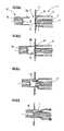
- FIG. 10is a diagram illustrating an arrangement of a power receiving connector and the like in the rear cover of a robot according to a second embodiment
- FIG. 11is a diagram illustrating an arrangement of essential internal components of a charging station according to the second embodiment
- FIG. 12is a diagram illustrating connection between a power receiving connector and a power supplying connector according to the second embodiment.
- FIG. 1is a diagram showing a robot that is being charged on a charging station of the charging system according to this embodiment.
- FIG. 2is a plan view of the robot shown in FIG. 1 and some components arranged in the rear cover of the robot.
- FIG. 3( a )is a cross-sectional view of a power supplying connector and a power receiving connector
- FIG. 3( b )is a cross-sectional view taken along the line b-b in FIG. 3( a ).
- FIG. 4is a circuit diagram of the charging system according to this embodiment.
- FIG. 5is a flowchart illustrating a charging operation of the robot.
- FIGS. 1is a diagram showing a robot that is being charged on a charging station of the charging system according to this embodiment.
- FIG. 2is a plan view of the robot shown in FIG. 1 and some components arranged in the rear cover of the robot.
- FIG. 3( a )is a cross-sectional view of a power supplying connector
- FIGS. 6( a ) to 6 ( d )are diagrams for illustrating the charging operation of the robot.
- FIGS. 7( a ) and 7 ( b )are diagrams for illustrating a connecting operation in the case where the robot and the charging station are misaligned with each other.
- FIGS. 8( a ) to 8 ( d )are diagrams for illustrating connection between the power receiving connector and the power supplying connector.
- FIG. 9is a flowchart illustrating an operation of disconnecting the power receiving connector and the power supplying connector from each other.
- the charging system for a legged mobile robothas a charging station 20 that charges a battery 2 of a legged mobile robot 1 .
- the charging station 20comprises a holder (guide means) 21 that holds a rear cover 3 provided on the back of the robot 1 , a power supplying connector 22 provided on the holder 21 , a slide mechanism (moving means) 23 that holds the holder 21 and the power supplying connector 22 in a horizontally movable manner, a support strut 24 that supports the slide mechanism 23 , a base plate 25 that supports the support strut 24 in an upright position, and a charging power supply 26 that charges the battery 2 of the robot 1 .
- a reference position mark 27for the robot 1 to recognize the stopping position using a visual sensor (not shown) provided in the head of the robot 1 .
- the holder 21has first guide sections 21 a that horizontally radially extend toward the robot 1 and a second guide section 21 b that is substantially U-shaped when observed from a top view to conform to the contour of the rear cover 3 of the robot 1 .
- the first guide sections 21 a and the second guide section 21 bconstitute the guide means.
- the slide mechanism 23has a slide rail 23 a that extends horizontally and is fixed to the support strut 24 and a slide block 23 b that can move horizontally along the slide rail 23 a .
- the holder 21is fixed to the slide block 23 b via a rubber bush 23 c . This allows the holder 21 to move vertically and horizontally relative to the slide block 23 b to some extent.
- the power supplying connector 22extends forward (rightward in the drawing) from the center of the holder 21 .
- the power supplying connector 22has a block-shaped power supplying connector housing 28 and a power supplying terminal 29 in the power supplying connector housing 28 .
- the power supplying connector housing 28has protrusion members 28 a that protrude toward the power receiving connector 4 .
- the power supplying connector housing 28has latch fixing holes 28 b , into which a fitting latch 8 described later is inserted, formed in both lateral side surfaces thereof.
- the power supplying terminal 29is composed of a pair of charging terminals 29 a and 29 j and eight signal terminals 29 b to 29 i for signal transmission.
- the charging terminals 29 a and 29 jare disposed on both lateral sides of the signal terminals 29 b to 29 i .
- the charging terminals 29 a and 29 j of the power supplying terminal 29are flat terminals having recesses 29 a ′ and 29 j ′ in the contact surface, respectively, and the signal terminals 29 b to 29 i are flat terminals that have a flat contact surface.
- the power receiving connector 4is provided in the rear cover 3 of the robot 1 along with the battery 2 and is shielded from the outside of the rear cover 3 by a movable shutter member (lid member) 5 except during charging as shown in FIGS. 3( a ) and 3 ( b ).
- the movable shutter member 5is composed of a shutter 5 a that covers the surface of the power receiving connector 4 , a shutter case 5 b that holds one edge of the shutter 5 a so that the shutter 5 a can pivot about the edge, and a shutter spring 5 c that biases the shutter case 5 b toward the surface of the rear cover 3 .
- the power receiving connector 4has a power receiving connector housing 6 and a power receiving terminal 7 capable of moving back and forth provided in the power receiving connector housing 6 .
- the power receiving connector 4has a pair of fitting latches 8 capable of moving back and forth in a direction perpendicular to the direction of attachment and detachment of the power supplying connector 22 .
- the power receiving terminal 7is composed of charging terminals 7 a and 7 j to which a charging current is supplied and eight signal terminals 7 b to 7 i for signal transmission.
- the charging terminals 7 a and 7 jare disposed on both lateral sides of the signal terminals 7 b to 7 i .
- the charging terminals 7 a and 7 j and the signal terminals 7 b to 7 ihave a semispherical tip and are spring-pin-type terminals that are biased toward the power supplying terminal 29 by a spring 9 .
- the charging terminals 7 a and 7 jextend toward the power supplying connector 22 beyond the tips of the signal terminals 7 b to 7 i.
- the fitting latch 8has a claw member 8 a that can move back and forth and has a chamfered, arc-shaped edge at one side at which the claw member 8 a comes into contact with the power supplying connector 22 , a spring 8 b for biasing the claw member 8 a in a direction that the claw member 8 a protrudes, a solenoid 8 c for pulling the claw-member 8 a in a direction that the claw member 8 a is retracted, and an unlatching detection switch 8 d that detects unlatching when the claw member 8 a is kept in the retracted position.
- the fitting latches 8 and the latch fixing holes 28 b formed in the power supplying connector 22constitute a locking mechanism.
- the robot 1has a controller 30 that controls the operations of the arms, the legs and the like of the robot 1 and serves as charge control means during charging, and an unlatching switch 31 that performs unlatching using the solenoid 8 c of the fitting latch 8 .
- the robot 1has a pair of charging lines 32 a and 32 j connected to the charging terminals 7 a and 7 j , a power supply output OFF line 33 connected to the signal terminal 7 b for transmitting a power supply output OFF signal, and an unlatching command line 34 that connects the unlatching switch 31 and the controller 30 to each other.
- the controller 30 and the signal terminal 7 d of the power-receiving connector 4are connected to each other via a connection detection line 35 .
- connection detection line 35is connected to the signal terminal 7 e of the power receiving connector 4 via a line 36 described later and grounded via a line 37 . Furthermore, the connection detection line 35 is connected to a power supply Vcc via a resistor 38 a .
- the unlatching switch 31is intended to interrupt electric power supply from the power supply Vcc to the solenoid 8 c , the line to the power supply Vcc is connected to an unlatching command line 39 via a resistor 38 b , and the unlatching command line 39 is connected to the unlatching detection switch 8 d.
- the charging station 20has a pair of charging lines 40 a and 40 j extending from the charging power supply 26 and connected to the charging terminals 29 a and 29 j , a power supply output OFF line 41 connected to the signal terminal 29 b for receiving the power supply output OFF signal, and a line 36 that connects the signal terminals 29 d and 29 e to each other.
- the controller 30 , the connection detection line 35 , the line 36 and the line 37constitute connection detecting means.
- the robot 1searches for and locates the charging station 20 with the visual sensor (not shown). Once the visual sensor locates the charging station 20 , the controller 30 makes the robot 1 move to a predetermined position near the charging station 20 (step S 1 ). Then, the robot 1 performs a first positioning to a predetermined position on the base plate 25 of the charging station 20 (step S 2 ). Then, the robot 1 makes a 180-degree turn to aim the rear cover 3 at the holder 21 (step S 3 ).
- the robot 1determines the position at which the robot 1 should rest with reference to the reference position mark 27 on the surface of the base plate 25 of the charging station 20 and performs a second positioning (step S 4 ). Then, the robot 1 shifts the center of gravity rearward to displace the waist rearward, thereby bringing the rear cover 3 close to the holder 21 (step S 5 ).
- the holder 21 and the rear cover 3are slightly horizontally misaligned with each other as shown in FIG. 7( a ), the holder 21 is aligned to the rear cover 3 as described below.
- the rear cover 3abuts against the first guide section 21 a of the holder 21 . If the rear cover 3 further moves toward the holder 21 from this state, the rear cover 3 pushes the holder 21 leftward in FIG. 7( a ). Since the slide mechanism 23 enables the holder 21 to move horizontally, when the rear cover 3 pushes the first guide section 21 a of the holder 21 , the holder 21 slides upward in FIG. 7 ( b ). And the rear cover 3 is guided by the first guide section 21 a of the holder 21 and housed in the second guide section 21 b . In this way, the power receiving connector 4 and the power supplying connector 22 are horizontally aligned with each other.
- the holder 21does not have a vertical alignment mechanism like the horizontal slide mechanism but has a simple mechanism, such as the rubber bush 23 c.
- FIG. 8an operation of connecting the power receiving connector 4 to the power supplying connector 22 will be described.
- the state shown in FIG. 8( a )changes to the state shown in FIG. 8( b ).
- the protrusion members 28 a of the power supplying connector housing 28comes into contact with the shutter case 5 b of the movable shutter member 5 .
- the protrusion members 28 a of the power supplying connector housing 28are formed to abut against the shutter case 5 b at both lateral sides of the shutter 5 a in the side view. Therefore, if the power supplying connector housing 28 is pushed rightward in FIG.
- the shutter case 5 bmoves rightward while pushing the shutter spring 5 c .
- the shutter 5 ais pushed by the power receiving connector housing 6 and opened.
- the power supplying connector housing 28is further pushed rightward from the state shown in FIG. 8( c )
- the power supplying terminal 29 and the power receiving terminal 7come into contact with each other and are connected to each other as shown in FIG. 8( d ).
- the charging terminals 7 a and 7 j of the power receiving terminal 7protrude toward the power supplying connector 22 beyond the tips of the signal terminals 7 b to 7 i as shown in FIG. 3( a )
- the charging terminals 7 a and 7 jfirst come into contact with the charging terminals 29 a and 29 j .
- the springs 9 of the charging terminals 7 a and 7 jare pressed, and the signal terminals 7 b to 7 i come into contact with the signal terminals 29 b to 29 i.
- connection detection line 35is grounded via the line 36 on the power supplying connector 22 , the signal terminal 7 e and the line 37 , and thus, connection between the power receiving terminal 7 and the power supplying terminal 29 is detected (Yes in step S 6 ). If the unlatching detection switch 8 d is not opened in this state, the controller 30 determines that the fitting latches 8 are normally fitted into the latch fixing holes 28 b (Yes in step S 7 ).
- step S 8the controller 30 permits the charging operation (step S 8 ), allowing the charging power supply 26 to supply a charging current to the battery 2 via the charging terminals 29 a and 29 j and the charging terminals 7 a and 7 j , thereby charging the battery 2 (step S 9 ).
- step S 10charging of the battery continues until the controller 30 confirms that the battery 2 is completely charged (Yes in step S 11 ). If a work request is externally received (if Yes in step S 10 ), the controller 30 extracts a work model, which is the same as or similar to the requested work, from a plurality of work models stored in a storage device (not shown) of the controller 30 and calculates the workload (step S 14 ). Then, based on the calculated workload, the controller 30 determines whether the current remaining capacity of the battery 2 suffices for the work (step S 15 ) and, if the current remaining capacity suffices for the work, terminates the charging operation and carries out the requested work. If the current remaining capacity of the battery does not suffice for the requested work, the controller 30 informs the person who has requested the work that the work cannot be carried out (step S 16 ) and continues the charging operation (No in step S 11 ).
- the slide mechanism 23enables wide horizontal movement of the holder 21 .
- the power receiving terminal 7is a spring-pin-type terminal
- the power supplying terminal 29is a flat terminal, and such characteristics of the terminals can also help to accommodate misalignment between the terminals to some extent. Therefore, in most cases, charging of the robot 1 can be accomplished by the process described above.
- step (S 6 )connection between the power receiving terminal 7 and the power supplying terminal 29 is not detected in step (S 6 ) described above within a predetermined time from the time when the rear cover 3 is brought close to the holder 21 in step (S 5 ) described above for some reason, or in the case where fitting of the fitting latches 8 into the latch fixing holes 28 b is not confirmed in step (S 7 ) described above, an error process is carried out as described below.
- the robot 1detects the deviation of the standing position thereof from the lateral center position of the charging station 20 by means of the visual sensor (not shown) that detects the reference position mark 27 on the base plate 25 . If the deviation falls within a limit value and can be compensated for only by moving the waist, without moving the legs (Yes in step S 12 ), the robot 1 moves the waist to adjust the position of the power receiving connector 4 (step S 5 ). On the other hand, if the deviation exceeds the limit value and cannot be compensated for without the leg movement (No in step S 12 ), the position of the waist is restored to the position before connection (step S 13 ), and the second positioning is carried out again (step S 4 ).
- step S 11when the charging is completed (Yes in step S 11 ), or when a work is externally requested, and the work can be carried out (Yes in step S 15 ), a separation operation described below is started.
- the controller 30transmits the power supply-output OFF signal to the charging station 20 via the power supply output OFF lines 33 and 41 .
- the charging current supplied from the charging power supply 26 to the battery 2is interrupted (step S 21 ).
- step S 23when the voltage between the paired charging terminals 7 a and 7 j becomes lower than a predetermined threshold (Yes in step S 22 ), the controller 30 performs the unlatching process of the fitting latches 8 (step S 23 ).
- the unlatching process of the fitting latches 8is performed with the unlatching switch 31 closed by the controller 30 and the solenoid 8 c energized by the power supply Vcc.
- the claw members 8 aare drawn toward the respective solenoids 8 c and disengaged from the latch fixing holes 28 b in the power supplying connector housing 28 of the power supplying connector 22 , so that the power receiving connector 4 and the power supplying connector 22 can be disconnected from each other.
- the unlatching detection switch 8 dis turned on, and the controller 30 is informed of the unlatching of the fitting latches 8 (Yes in step S 24 ).
- the controller 30controls the robot 1 to move the waist of the robot 1 back to the position before charging (step S 25 ).
- the signal terminals 7 b to 7 i and the signal terminals 29 b to 29 iare also disconnected from each other, so that the connection detection line 35 is opened.
- the controller 30confirms that the power receiving connector 4 and the power supplying connector 22 are normally disconnected from each other (Yes in step S 26 ). In this way, separation of the robot 1 from the charging station 20 is completed.
- the shutter spring 5 cpushes the shutter case 5 b , so that the state shown in FIG. 8( d ) changes back to the state shown in FIG. 8( a ), and the front of the power receiving connector 4 is closed by the shutter 5 a.
- step S 28If the voltage between the paired charging terminals 7 a and 7 j does not become lower than the predetermined threshold in step (S 22 ) described above, if the unlatching of the fitting latches 8 is not detected in step (S 24 ) described above, or if it is determined that the waist of the robot 1 has to be moved beyond a limit value in step (S 27 ), an error process is carried out by informing the abnormality by an alarm or the like provided in the robot 1 , for example (step S 28 ).
- the charging systemcan charge the robot 1 without laterally moving the center of gravity of the robot 1 , so that the robot 1 can be easily controlled during charging.
- the center of gravity of the robot 1does not laterally move, and the robot 1 can lean against the charging station 20 during charging, the power required to maintain the posture of the robot 1 during charging can be reduced.
- the power receiving terminal 7is housed in the rear cover 3 of the robot 1 except during charging, there is no possibility that the power receiving terminal 7 comes into contact with an outside obstacle and is damaged thereby when the robot 1 moves.
- the charging terminals 7 a and 7 j of the power receiving terminal 7protrude toward the power supplying connector 22 beyond the tips of the signal terminals 7 b to 7 i , spark discharge can be prevented from occurring on the signal terminals 7 b to 7 i , so that deterioration of the terminals due to the spark discharge can be prevented.
- the charging terminals 29 a and 29 j of the power supplying connector 22have the recesses 29 a ′ and 29 j ′, respectively, formed in the contact surface, and the charging terminals 7 a and 7 j of the power receiving connector 4 have the semispherical tip. Therefore, the charging connectors 29 a and 29 j and the charging connectors 7 a and 7 j are in surface contact with each other over a wide contact area. As a result, the resistance between the terminals is reduced.
- the holder 21has the first guide sections 21 a and the second guide section 21 b .
- the present inventionis not limited thereto, and the holder 21 may have only a component like the first guide sections 21 a , which extend horizontally radially toward the robot 1 .
- the holder 21 and the slide block 23 bare coupled with each other by the rubber bush 23 c .
- the present inventionis not limited thereto, and a slide mechanism capable of moving vertically and horizontally may be provided to enable the slide block 23 b to slide not only horizontally but also vertically.
- FIG. 10is a diagram illustrating an arrangement of a power receiving connector and the like in the rear cover of a robot according to the second embodiment.
- FIG. 11is a diagram illustrating an arrangement of essential internal components of a charging station according to the second embodiment.
- FIG. 12is a diagram showing connection between a power receiving connector and a power supplying connector according to the second embodiment.
- the same components as in the embodiment described aboveare denoted by the same reference numerals, and detailed description thereof will be omitted.
- illustration of the shutter member of a rear cover 3 of a robot 1 ′is omitted.
- the charging system according to the second embodimenthas a charging station 20 ′ that charges a battery 2 (see FIG. 1 ) of a legged mobile robot 1 ′.
- the charging systemhas a power receiving connector 4 shown in FIG. 10 and a power supplying connector 22 shown in FIG. 11 that are the same as those in the embodiment described above and a circuit arrangement that is the same as that shown in FIG. 4 except for the part involved with the fitting latch 8 .
- the charging system according to the second embodimenthas guide means, a locking mechanism and moving means that are different from those according to the embodiment described above.
- the guide meansis composed of a pair of guide sleeves 50 provided on the robot 1 ′ and a pair of guide pins 60 ( 60 a , 60 b ) provided on the charging station 20 ′.
- the guide sleeves 50are metal cylinders having a widened open end.
- the guide sleeves 50are disposed on the left and right sides of the power receiving connector 4 on the robot 1 ′.
- the guide pins 60 a and 60 bare circular columns made of metal having a conical tip.
- the guide pins 60 a and 60 bare disposed on the left and right sides of the power supplying connector 22 on the charging station 20 ′.
- the locking mechanismis composed of guide slits 51 formed in the guide sleeves 50 , engaging pins (engaging protrusions) 61 formed on the periphery of the guide pins 60 and capable of moving in the guide slits 51 , a guide pin motor 62 (rotating means) for rotating the guide pin 60 a of the pair of guide pins 60 a and 60 b , and a linkage mechanism 63 coupled to the guide pin motor 62 to rotate the other guide pin 60 b .
- the guide slit 51is composed of a longitudinal slit 51 a extending in the axial direction of the guide sleeve 50 toward the open end thereof and an engaging slit 51 b extending in the circumferential direction of the guide sleeve 50 from the inner end of the longitudinal slit 51 a .
- a pair of such guide slits 51are formed in the left and right walls of the guide sleeve 50 .
- the engaging slits 51 b of the paired guide slits 51extend in the same direction (clockwise in the second embodiment) when seen from the side of the open end of the guide sleeve 50 .
- the engaging pins 61are circular columns made of metal, which penetrate through the respective guide pins 60 and are fixed thereto.
- the guide pin motor 62is disposed at the bottom of the guide pin 60 a and fixed to a connector holder 64 that holds the power supplying connector 22 and the guide pins 60 a and 60 b .
- the linkage mechanism 63is a member that couples the rotary part of the guide pin motor 62 to the other guide pin 60 b , thereby rotating the other guide pin 60 b in addition to the guide pin 60 a .
- the connector holder 64has a position sensor 65 for detecting the position of the robot 1 ′ on the surface facing the robot 1 ′.
- the position sensor 65detects that the guide pins 60 are inserted into the respective guide sleeves 50 , and the engaging pins 61 reach the inner ends of the longitudinal slits 51 a of the guide slits 51 based on the distance between the rear cover 3 ′ of the robot 1 ′ and the position sensor 65 .
- the moving meansis composed of a first rubber floating 66 and a second rubber floating 67 (floating part) shown in FIG. 11 .
- the first rubber floating 66has a cylindrical shape and has a coil spring 66 a integrally formed therein. With such a configuration, the axial length of the first rubber floating 66 can be expanded or shrunk by a predetermined length (about 25 mm in the second embodiment).
- the first rubber floating 66couples a supporting rod 68 described later and the rear part of the connector holder 64 to each other.
- the supporting rob 68is a cylindrical rod member and is held in the charging station 20 ′ by a fulcrum holder 69 , the second rubber floating 67 and a floating holder 70 .
- the supporting rod 68has a double-pipe configuration between the connector holder 64 and the fulcrum holder 69 , and the distance between the connector holder 64 and the fulcrum holder 69 can be changed. Since the connector holder 64 and the supporting rod 68 are coupled to each other by the first rubber floating 66 , the distance between the connector holder 64 and the fulcrum holder 69 can be changed by about 25 mm.
- the second rubber floating 67is a circular column member, through the center of which the supporting rod 68 penetrates, and is held by the floating holder 70 at the periphery thereof. Since the supporting rod 68 is supported by the second rubber, floating 67 , the supporting rod 68 can radially move by a predetermined amount (about 4 mm in the second embodiment) due to the resiliency of the second rubber floating 67 .
- a balance weight 71is mounted on the supporting rod 68 at a position behind the second rubber floating 67 .
- the fulcrum holder 69 and the floating holder 70are both fixed to a supporting plate 72 in the charging station 20 ′.
- the supporting plate 72can be moved in the axial direction of the supporting rod 68 by an axial actuator 73 .
- the robot 1 ′For charging the robot 1 ′, the robot 1 ′ is moved to a predetermined position on the charging station 20 ′ through the steps S 1 to S 4 shown in FIG. 5 . Then, the robot 1 ′ displaces the waist position rearward by displacing the center of gravity as in step S 5 shown in FIG. 5 , thereby bringing the power receiving connector 4 close to the power supplying connector 22 .
- the guide pins 60can be inserted into the depth of the guide sleeves 50 along the inner surface of the guide sleeves 50 , because the tips of the guide pins 60 are conical, and the open ends of the guide sleeves 50 are widened.
- the guide pins 60are fixed to the connector holder 64 , the connector holder 64 is coupled to the supporting rod 68 , and the supporting rod 68 is supported swingably by the charging station 20 ′ via the fulcrum holder 69 and held by the second rubber floating 67 in such a manner that the supporting rod 68 can radially move by a predetermined amount.
- the guide pins 60can also radially move by the predetermined amount.
- the charging system according to the second embodimentcan always smoothly establish the connection between the power supplying connector 22 and the power receiving connector 4 .
- the position sensor 65detects that the engaging pins 61 on the guide pins 60 reach the inner ends of the longitudinal slits 51 a and informs a controller 30 of that.
- the controller 30makes the guide pin motor 62 rotate the guide pin 60 a and the linkage mechanism 63 rotate the other guide pin 60 b , thereby making the engaging pins 61 enter the engaging slits 51 b of the guide slits 51 . Then, the controller 30 stops the movement of the guide pins 60 a and 60 b in this state.
- the power receiving connector 4 and the power supplying connector 22are connected to each other with reliability. Then, after it is confirmed that a power receiving terminal 7 and a power supplying terminal 29 are connected to each other as in step S 6 in FIG. 4 , the controller 30 starts charging of the battery 2 of the robot 1 ′. At this time, even if an external force is exerted on the robot 1 ′ for some reason, the connectors are not disconnected during charging because the guide pins 60 and the guide sleeves 50 are engaged with each other by the engaging pins 61 and the engaging slits 51 b.
- the controller 30makes the guide pin motor 62 rotate in the direction opposite to that for connecting the connectors, thereby moving the engaging pins 61 on the guide pins 60 from the engaging slits 51 b to the longitudinal slits 51 a of the guide slits 51 formed in the guide sleeves 50 .
- the controller 30controls the robot 1 ′ to restore the position of the waist of the robot 1 ′ before charging (see S 25 in FIG. 9 ).
- the power receiving connector 4 and the power supplying connector 22are disconnected from each other.
- the remaining steps of the control operationare the same as those shown in FIG. 9 excluding steps S 23 and S 24 .
- the guide pins 60 and the guide sleeves 50constitute the guide means and the locking mechanism, and the first rubber floating 66 and the second rubber floating 67 constitute the moving means.
- the whole of the charging systemcan be downsized.
- the charging station 20 ′can be made compact in its widthdirection, which leads to improvement in the flexibility of layout in installing the charging station ' 20 .
- the supporting plate 72can be moved in the axial direction of the supporting rod 68 by the axial actuator 73 shown in FIG. 11 . Therefore, for example, even if the robot 1 ′ to be charged is erroneously positioned, and the position sensor 65 detects that the power receiving connector 4 and the power supplying connector 22 are spaced apart from each other, the positions of the connectors can be adjusted by the axial actuator 73 . Furthermore, the axial actuator 73 enables the power supplying connector 22 and the guide pins 60 to be exposed to the outside of the charging station 20 ′ when the robot 1 ′ comes close to the charging station 20 ′ for charging and to be housed in the charging station 20 ′ when charging of the robot 1 ′ is not performed. Furthermore, since the axial actuator 73 can move the power supplying connector 22 toward the power receiving connector 4 , the robot 1 ′ can be charged in the upright position, rather than leaning against the charging station 20 ′.
- the present inventionis not limited thereto, and the guide pins 60 may be provided on the side of the power receiving connector 4 , and the guide sleeves 50 may be provided on the side of the power supplying connector 22 .
- the locking mechanismis constituted by the engaging pins 61 on the guide pins 60 and the guide slits 51 formed in the guide sleeves 50 according to the second embodiment, a fitting latch 8 may be used as in the embodiment described above.
- the moving meansis constituted by the first rubber floating 66 and the second rubber floating 67 according to the second embodiment, either one of the rubber floatings may be omitted if a single rubber floating suffices for movement of the power supplying connector 22 and the guide pins 60 in the radial direction of the guide pins 60 .
Landscapes
- Engineering & Computer Science (AREA)
- Mechanical Engineering (AREA)
- Radar, Positioning & Navigation (AREA)
- Power Engineering (AREA)
- Transportation (AREA)
- Aviation & Aerospace Engineering (AREA)
- Robotics (AREA)
- Remote Sensing (AREA)
- Physics & Mathematics (AREA)
- General Physics & Mathematics (AREA)
- Automation & Control Theory (AREA)
- Manipulator (AREA)
- Charge And Discharge Circuits For Batteries Or The Like (AREA)
- Secondary Cells (AREA)
Abstract
Description
Claims (11)
Applications Claiming Priority (6)
| Application Number | Priority Date | Filing Date | Title |
|---|---|---|---|
| JP2006-37151 | 2006-02-14 | ||
| JP2006-037151 | 2006-02-14 | ||
| JP2006037151 | 2006-02-14 | ||
| JP2007-033344 | 2007-02-14 | ||
| JP2007-33344 | 2007-02-14 | ||
| JP2007033344AJP2007245332A (en) | 2006-02-14 | 2007-02-14 | Charging system for legged mobile robot |
Publications (2)
| Publication Number | Publication Date |
|---|---|
| US20070216347A1 US20070216347A1 (en) | 2007-09-20 |
| US7719229B2true US7719229B2 (en) | 2010-05-18 |
Family
ID=38179784
Family Applications (1)
| Application Number | Title | Priority Date | Filing Date |
|---|---|---|---|
| US11/705,772Expired - Fee RelatedUS7719229B2 (en) | 2006-02-14 | 2007-02-14 | Charging system for legged mobile robot |
Country Status (3)
| Country | Link |
|---|---|
| US (1) | US7719229B2 (en) |
| EP (1) | EP1819026A3 (en) |
| JP (1) | JP2007245332A (en) |
Cited By (56)
| Publication number | Priority date | Publication date | Assignee | Title |
|---|---|---|---|---|
| US20090169347A1 (en)* | 2007-12-28 | 2009-07-02 | Industrial Technology Research Institute | Workstation |
| US20100010672A1 (en)* | 2008-07-10 | 2010-01-14 | Yulun Wang | Docking system for a tele-presence robot |
| US20100131102A1 (en)* | 2008-11-25 | 2010-05-27 | John Cody Herzog | Server connectivity control for tele-presence robot |
| US20100286823A1 (en)* | 2008-01-15 | 2010-11-11 | Honda Motor Co., Ltd. | Robot |
| US20110213210A1 (en)* | 2009-08-26 | 2011-09-01 | Intouch Technologies, Inc. | Portable telepresence apparatus |
| US20120025761A1 (en)* | 2010-07-29 | 2012-02-02 | Toyota Jidosha Kabushiki Kaisha | Resonance type non-contact power supply system for vehicle and electric vehicle |
| US8340819B2 (en) | 2008-09-18 | 2012-12-25 | Intouch Technologies, Inc. | Mobile videoconferencing robot system with network adaptive driving |
| US8401275B2 (en) | 2004-07-13 | 2013-03-19 | Intouch Technologies, Inc. | Mobile robot with a head-based movement mapping scheme |
| US8515577B2 (en) | 2002-07-25 | 2013-08-20 | Yulun Wang | Medical tele-robotic system with a master remote station with an arbitrator |
| US8670017B2 (en) | 2010-03-04 | 2014-03-11 | Intouch Technologies, Inc. | Remote presence system including a cart that supports a robot face and an overhead camera |
| US8836751B2 (en) | 2011-11-08 | 2014-09-16 | Intouch Technologies, Inc. | Tele-presence system with a user interface that displays different communication links |
| US8849679B2 (en) | 2006-06-15 | 2014-09-30 | Intouch Technologies, Inc. | Remote controlled robot system that provides medical images |
| US8849680B2 (en) | 2009-01-29 | 2014-09-30 | Intouch Technologies, Inc. | Documentation through a remote presence robot |
| US20140292274A1 (en)* | 2013-03-15 | 2014-10-02 | Symbotic, LLC | Rover charging system |
| US8861750B2 (en) | 2008-04-17 | 2014-10-14 | Intouch Technologies, Inc. | Mobile tele-presence system with a microphone system |
| US20140340021A1 (en)* | 2013-05-20 | 2014-11-20 | Hon Hai Precision Industry Co., Ltd. | Portable electrical power source |
| US8897920B2 (en) | 2009-04-17 | 2014-11-25 | Intouch Technologies, Inc. | Tele-presence robot system with software modularity, projector and laser pointer |
| US8902278B2 (en) | 2012-04-11 | 2014-12-02 | Intouch Technologies, Inc. | Systems and methods for visualizing and managing telepresence devices in healthcare networks |
| US8965579B2 (en) | 2011-01-28 | 2015-02-24 | Intouch Technologies | Interfacing with a mobile telepresence robot |
| US8996165B2 (en) | 2008-10-21 | 2015-03-31 | Intouch Technologies, Inc. | Telepresence robot with a camera boom |
| US9098611B2 (en) | 2012-11-26 | 2015-08-04 | Intouch Technologies, Inc. | Enhanced video interaction for a user interface of a telepresence network |
| US9160783B2 (en) | 2007-05-09 | 2015-10-13 | Intouch Technologies, Inc. | Robot system that operates through a network firewall |
| US9174342B2 (en) | 2012-05-22 | 2015-11-03 | Intouch Technologies, Inc. | Social behavior rules for a medical telepresence robot |
| US9198728B2 (en) | 2005-09-30 | 2015-12-01 | Intouch Technologies, Inc. | Multi-camera mobile teleconferencing platform |
| USRE45870E1 (en) | 2002-07-25 | 2016-01-26 | Intouch Technologies, Inc. | Apparatus and method for patient rounding with a remote controlled robot |
| US9251313B2 (en) | 2012-04-11 | 2016-02-02 | Intouch Technologies, Inc. | Systems and methods for visualizing and managing telepresence devices in healthcare networks |
| US9264664B2 (en) | 2010-12-03 | 2016-02-16 | Intouch Technologies, Inc. | Systems and methods for dynamic bandwidth allocation |
| US9296107B2 (en) | 2003-12-09 | 2016-03-29 | Intouch Technologies, Inc. | Protocol for a remotely controlled videoconferencing robot |
| US9323250B2 (en) | 2011-01-28 | 2016-04-26 | Intouch Technologies, Inc. | Time-dependent navigation of telepresence robots |
| US9361021B2 (en) | 2012-05-22 | 2016-06-07 | Irobot Corporation | Graphical user interfaces including touchpad driving interfaces for telemedicine devices |
| USD760649S1 (en) | 2015-06-22 | 2016-07-05 | Mtd Products Inc | Docking station |
| USD762567S1 (en)* | 2013-10-11 | 2016-08-02 | Mimoco | USB battery charger |
| US9602765B2 (en) | 2009-08-26 | 2017-03-21 | Intouch Technologies, Inc. | Portable remote presence robot |
| US9610685B2 (en) | 2004-02-26 | 2017-04-04 | Intouch Technologies, Inc. | Graphical interface for a remote presence system |
| US9842192B2 (en) | 2008-07-11 | 2017-12-12 | Intouch Technologies, Inc. | Tele-presence robot system with multi-cast features |
| US9974612B2 (en) | 2011-05-19 | 2018-05-22 | Intouch Technologies, Inc. | Enhanced diagnostics for a telepresence robot |
| US20180201146A1 (en)* | 2015-07-08 | 2018-07-19 | Jiangsu University | Charging device of automatic cruise platform for greenhouse |
| US10059000B2 (en) | 2008-11-25 | 2018-08-28 | Intouch Technologies, Inc. | Server connectivity control for a tele-presence robot |
| US20190052101A1 (en)* | 2017-08-14 | 2019-02-14 | Ubtech Robotics Corp | Robot recharging dock and robot recharging system |
| US10207595B2 (en) | 2010-12-15 | 2019-02-19 | Symbotic, LLC | Autonomous transport vehicle charging system |
| US10343283B2 (en) | 2010-05-24 | 2019-07-09 | Intouch Technologies, Inc. | Telepresence robot system that can be accessed by a cellular phone |
| US10471588B2 (en) | 2008-04-14 | 2019-11-12 | Intouch Technologies, Inc. | Robotic based health care system |
| US10769739B2 (en) | 2011-04-25 | 2020-09-08 | Intouch Technologies, Inc. | Systems and methods for management of information among medical providers and facilities |
| US10808882B2 (en) | 2010-05-26 | 2020-10-20 | Intouch Technologies, Inc. | Tele-robotic system with a robot face placed on a chair |
| US10875182B2 (en) | 2008-03-20 | 2020-12-29 | Teladoc Health, Inc. | Remote presence system mounted to operating room hardware |
| US11154981B2 (en) | 2010-02-04 | 2021-10-26 | Teladoc Health, Inc. | Robot user interface for telepresence robot system |
| US11289842B2 (en)* | 2017-04-21 | 2022-03-29 | Hilti Aktiengesellschaft | Spring contact on a rechargeable battery |
| US11322958B2 (en)* | 2019-10-23 | 2022-05-03 | Lg Electronics Inc. | Charging station |
| US20220194245A1 (en)* | 2020-12-22 | 2022-06-23 | Boston Dynamics, Inc. | Robust Docking of Robots with Imperfect Sensing |
| US11389064B2 (en) | 2018-04-27 | 2022-07-19 | Teladoc Health, Inc. | Telehealth cart that supports a removable tablet with seamless audio/video switching |
| US11636944B2 (en) | 2017-08-25 | 2023-04-25 | Teladoc Health, Inc. | Connectivity infrastructure for a telehealth platform |
| US11742094B2 (en) | 2017-07-25 | 2023-08-29 | Teladoc Health, Inc. | Modular telehealth cart with thermal imaging and touch screen user interface |
| US11862302B2 (en) | 2017-04-24 | 2024-01-02 | Teladoc Health, Inc. | Automated transcription and documentation of tele-health encounters |
| USD1032509S1 (en) | 2021-04-23 | 2024-06-25 | Mtd Products Inc | Docking station |
| US12093036B2 (en) | 2011-01-21 | 2024-09-17 | Teladoc Health, Inc. | Telerobotic system with a dual application screen presentation |
| US12224059B2 (en) | 2011-02-16 | 2025-02-11 | Teladoc Health, Inc. | Systems and methods for network-based counseling |
Families Citing this family (48)
| Publication number | Priority date | Publication date | Assignee | Title |
|---|---|---|---|---|
| JP4893887B2 (en) | 2007-04-02 | 2012-03-07 | 本田技研工業株式会社 | Charger |
| JP5449675B2 (en) | 2007-09-21 | 2014-03-19 | 富士フイルム株式会社 | Photosensitive composition, pattern forming method using the photosensitive composition, and compound used in the photosensitive composition |
| JP4882114B2 (en)* | 2007-11-09 | 2012-02-22 | 本田技研工業株式会社 | Charging device and charging method for walking robot |
| JP4552037B2 (en)* | 2007-12-10 | 2010-09-29 | 本田技研工業株式会社 | robot |
| CN101607399A (en)* | 2008-06-19 | 2009-12-23 | 鸿富锦精密工业(深圳)有限公司 | Charging device |
| TWM377001U (en)* | 2009-10-16 | 2010-03-21 | Micro Star Int Co Ltd | Electronic device |
| US8212533B2 (en)* | 2009-12-23 | 2012-07-03 | Toyota Motor Engineering & Manufacturing North America, Inc. | Robot battery charging apparatuses and methods |
| FR2962859B1 (en)* | 2010-07-15 | 2012-09-21 | Electro Alu | CONNECTION MODULE |
| US20120091824A1 (en)* | 2010-10-19 | 2012-04-19 | Leviton Manufacturing Co., Inc. | Electric Vehicle Supply Equipment with Line Fitting Disconnect Sensing |
| DE102010043056A1 (en)* | 2010-10-28 | 2012-05-03 | Robert Bosch Gmbh | Method for charging a hybrid or electric vehicle |
| CN102565754B (en)* | 2010-11-30 | 2014-02-26 | 华硕电脑股份有限公司 | Positioning method and system for mobile device |
| JP5898002B2 (en)* | 2012-06-28 | 2016-04-06 | 本田技研工業株式会社 | Mobile robot controller |
| KR101964372B1 (en)* | 2012-11-21 | 2019-04-01 | 한화디펜스 주식회사 | Docking module |
| ES2638186T3 (en) | 2013-03-27 | 2017-10-19 | Abb Technology Ag | Drive inverter shared by different engines in a vehicle |
| DK3031105T3 (en)* | 2013-08-09 | 2021-07-26 | Schunk Transit Sys Gmbh | Fast charging system and method for electrically connecting a vehicle to a charging station |
| KR101469204B1 (en)* | 2014-02-06 | 2014-12-09 | 한국기계연구원 | Worktable fixation device for robot |
| KR101469203B1 (en)* | 2014-02-06 | 2014-12-09 | 한국기계연구원 | Worktable fixation device for robot |
| FR3049359B1 (en)* | 2016-03-23 | 2020-01-10 | Aldebaran Robotics | METHOD FOR RECHARGING A BATTERY |
| US9840154B2 (en) | 2016-04-01 | 2017-12-12 | Locus Robotics Corporation | Electrical charging system for a robot |
| WO2018027572A1 (en)* | 2016-08-09 | 2018-02-15 | 衣佳鑫 | Electric quantity control method and system for robot in internet of things |
| CN106254188A (en)* | 2016-08-09 | 2016-12-21 | 衣佳鑫 | Robot electric quantity control method and system in Internet of Things |
| WO2018064810A1 (en)* | 2016-10-08 | 2018-04-12 | 浙江国自机器人技术有限公司 | Mobile robot autonomous charging device |
| CN107017676A (en)* | 2017-04-28 | 2017-08-04 | 浙江国自机器人技术有限公司 | A kind of mobile robot recharging device |
| CN107591857A (en)* | 2017-09-19 | 2018-01-16 | 上海悦合自动化技术有限公司 | The automatic charging equipment and its application method of mobile robot |
| US10243379B1 (en)* | 2017-09-22 | 2019-03-26 | Locus Robotics Corp. | Robot charging station protective member |
| CN107465277B (en)* | 2017-09-30 | 2024-02-09 | 深圳市锐曼智能装备有限公司 | Magnetic resonance type automatic charging robot and charging method thereof |
| WO2019082779A1 (en)* | 2017-10-23 | 2019-05-02 | Groove X株式会社 | Robot charging station |
| CN107748203B (en)* | 2017-11-16 | 2024-01-26 | 西安石油大学 | Intelligent self-tracking weld joint flaw detection robot |
| CN109932844B (en)* | 2017-12-15 | 2022-04-05 | 京东方科技集团股份有限公司 | Display panels and display devices |
| CN107933367B (en)* | 2017-12-19 | 2023-09-26 | 库卡机器人(广东)有限公司 | Charging device for unmanned carrier and unmanned carrier with charging device |
| CN109976324B (en)* | 2017-12-27 | 2022-06-28 | 深圳市优必选科技有限公司 | Method for controlling robot charging, robot, and computer-readable storage medium |
| CN108199432A (en)* | 2018-01-08 | 2018-06-22 | 浙江立石机器人技术有限公司 | A kind of automatic charge device of mobile robot |
| JP2019197681A (en)* | 2018-05-10 | 2019-11-14 | シャープ株式会社 | Electronic apparatus, charging stand, and charging system |
| CN109100745B (en)* | 2018-08-22 | 2020-08-07 | 江苏省江都水利工程管理处 | Automatic system of patrolling and examining of water conservancy pump station |
| JP7094628B2 (en)* | 2018-08-28 | 2022-07-04 | 矢崎総業株式会社 | Vehicle charging system |
| CN109512335B (en)* | 2018-11-28 | 2021-04-20 | 苏州凯丽达电器有限公司 | Dust collector charging terminal seat with adjustable charging terminal position |
| US11552488B2 (en)* | 2019-06-07 | 2023-01-10 | Te Connectivity Solutions Gmbh | Charging system for a mobile device |
| CN110198069B (en)* | 2019-07-04 | 2024-06-07 | 科大智能机器人技术有限公司 | Charging electrode device of inspection robot |
| CN110994710B (en)* | 2019-11-08 | 2023-02-24 | 合肥科大智能机器人技术有限公司 | Self-adaptive self-charging mechanism |
| JP7296857B2 (en)* | 2019-11-14 | 2023-06-23 | 三菱電機特機システム株式会社 | power supply |
| CN110957776B (en)* | 2019-11-15 | 2021-12-31 | 深圳市优必选科技股份有限公司 | Power supply structure, charging adjusting device and robot charging system |
| JP7327131B2 (en)* | 2019-12-05 | 2023-08-16 | オムロン株式会社 | charging unit |
| JP2021097452A (en)* | 2019-12-13 | 2021-06-24 | 株式会社日立ビルシステム | Charging device |
| JP7631859B2 (en) | 2020-02-20 | 2025-02-19 | 村田機械株式会社 | Charging Stations and Charging Systems |
| JP7339218B2 (en)* | 2020-08-11 | 2023-09-05 | 株式会社日立ビルシステム | Mobile charging system |
| JP7631906B2 (en)* | 2021-03-08 | 2025-02-19 | オムロン株式会社 | Charging unit |
| CN113852156B (en)* | 2021-09-15 | 2023-08-25 | 珠海格力电器股份有限公司 | Charging device, charging method, charging device, and computer-readable storage medium |
| CN116388342B (en)* | 2023-05-23 | 2023-10-27 | 江苏三里盛鑫工程技术有限公司 | Service type robot charging device |
Citations (3)
| Publication number | Priority date | Publication date | Assignee | Title |
|---|---|---|---|---|
| JP2001179663A (en) | 1999-12-24 | 2001-07-03 | Sony Corp | Leg type mobile robot, its control method and charging station |
| US6764373B1 (en)* | 1999-10-29 | 2004-07-20 | Sony Corporation | Charging system for mobile robot, method for searching charging station, mobile robot, connector, and electrical connection structure |
| JP2004298984A (en)* | 2003-03-31 | 2004-10-28 | Toyota Motor Corp | Walking robot |
Family Cites Families (6)
| Publication number | Priority date | Publication date | Assignee | Title |
|---|---|---|---|---|
| JPS6339776A (en)* | 1986-08-05 | 1988-02-20 | 工業技術院長 | Feed facility for independent travelling type robot |
| KR960011312B1 (en)* | 1994-03-31 | 1996-08-22 | 주식회사 에넥스 | Apparatus adjustable as to height of a sink |
| JPH0837705A (en)* | 1994-07-26 | 1996-02-06 | Toyota Motor Corp | Electric vehicle and charging device therefor |
| FR2736757B1 (en)* | 1995-07-11 | 1997-08-22 | Carrier Kheops Bac | ELECTRICAL CONNECTOR WITH AUTOMATIC PLUG |
| JP3988333B2 (en)* | 1999-09-09 | 2007-10-10 | 株式会社デンソー | Charging electrode structure of mobile robot |
| DE10258106A1 (en)* | 2002-12-11 | 2004-06-24 | Volkswagen Ag | Electric plug-in connection for sliding door on road vehicle has plug and/or bushing displaceably mounted in relation to respective housing |
- 2007
- 2007-02-14JPJP2007033344Apatent/JP2007245332A/enactivePending
- 2007-02-14USUS11/705,772patent/US7719229B2/ennot_activeExpired - Fee Related
- 2007-02-14EPEP07003132.3Apatent/EP1819026A3/ennot_activeWithdrawn
Patent Citations (3)
| Publication number | Priority date | Publication date | Assignee | Title |
|---|---|---|---|---|
| US6764373B1 (en)* | 1999-10-29 | 2004-07-20 | Sony Corporation | Charging system for mobile robot, method for searching charging station, mobile robot, connector, and electrical connection structure |
| JP2001179663A (en) | 1999-12-24 | 2001-07-03 | Sony Corp | Leg type mobile robot, its control method and charging station |
| JP2004298984A (en)* | 2003-03-31 | 2004-10-28 | Toyota Motor Corp | Walking robot |
Cited By (123)
| Publication number | Priority date | Publication date | Assignee | Title |
|---|---|---|---|---|
| US8515577B2 (en) | 2002-07-25 | 2013-08-20 | Yulun Wang | Medical tele-robotic system with a master remote station with an arbitrator |
| US10315312B2 (en) | 2002-07-25 | 2019-06-11 | Intouch Technologies, Inc. | Medical tele-robotic system with a master remote station with an arbitrator |
| US9849593B2 (en) | 2002-07-25 | 2017-12-26 | Intouch Technologies, Inc. | Medical tele-robotic system with a master remote station with an arbitrator |
| USRE45870E1 (en) | 2002-07-25 | 2016-01-26 | Intouch Technologies, Inc. | Apparatus and method for patient rounding with a remote controlled robot |
| US9375843B2 (en) | 2003-12-09 | 2016-06-28 | Intouch Technologies, Inc. | Protocol for a remotely controlled videoconferencing robot |
| US9956690B2 (en) | 2003-12-09 | 2018-05-01 | Intouch Technologies, Inc. | Protocol for a remotely controlled videoconferencing robot |
| US9296107B2 (en) | 2003-12-09 | 2016-03-29 | Intouch Technologies, Inc. | Protocol for a remotely controlled videoconferencing robot |
| US10882190B2 (en) | 2003-12-09 | 2021-01-05 | Teladoc Health, Inc. | Protocol for a remotely controlled videoconferencing robot |
| US9610685B2 (en) | 2004-02-26 | 2017-04-04 | Intouch Technologies, Inc. | Graphical interface for a remote presence system |
| US10241507B2 (en) | 2004-07-13 | 2019-03-26 | Intouch Technologies, Inc. | Mobile robot with a head-based movement mapping scheme |
| US8401275B2 (en) | 2004-07-13 | 2013-03-19 | Intouch Technologies, Inc. | Mobile robot with a head-based movement mapping scheme |
| US9766624B2 (en) | 2004-07-13 | 2017-09-19 | Intouch Technologies, Inc. | Mobile robot with a head-based movement mapping scheme |
| US8983174B2 (en) | 2004-07-13 | 2015-03-17 | Intouch Technologies, Inc. | Mobile robot with a head-based movement mapping scheme |
| US10259119B2 (en) | 2005-09-30 | 2019-04-16 | Intouch Technologies, Inc. | Multi-camera mobile teleconferencing platform |
| US9198728B2 (en) | 2005-09-30 | 2015-12-01 | Intouch Technologies, Inc. | Multi-camera mobile teleconferencing platform |
| US8849679B2 (en) | 2006-06-15 | 2014-09-30 | Intouch Technologies, Inc. | Remote controlled robot system that provides medical images |
| US10682763B2 (en) | 2007-05-09 | 2020-06-16 | Intouch Technologies, Inc. | Robot system that operates through a network firewall |
| US9160783B2 (en) | 2007-05-09 | 2015-10-13 | Intouch Technologies, Inc. | Robot system that operates through a network firewall |
| US20090169347A1 (en)* | 2007-12-28 | 2009-07-02 | Industrial Technology Research Institute | Workstation |
| US8040104B2 (en)* | 2007-12-28 | 2011-10-18 | Industrial Technology Research Institute | Workstation |
| US20100286823A1 (en)* | 2008-01-15 | 2010-11-11 | Honda Motor Co., Ltd. | Robot |
| US8380348B2 (en)* | 2008-01-15 | 2013-02-19 | Honda Motor Co., Ltd. | Robot |
| US10875182B2 (en) | 2008-03-20 | 2020-12-29 | Teladoc Health, Inc. | Remote presence system mounted to operating room hardware |
| US11787060B2 (en) | 2008-03-20 | 2023-10-17 | Teladoc Health, Inc. | Remote presence system mounted to operating room hardware |
| US10471588B2 (en) | 2008-04-14 | 2019-11-12 | Intouch Technologies, Inc. | Robotic based health care system |
| US11472021B2 (en) | 2008-04-14 | 2022-10-18 | Teladoc Health, Inc. | Robotic based health care system |
| US8861750B2 (en) | 2008-04-17 | 2014-10-14 | Intouch Technologies, Inc. | Mobile tele-presence system with a microphone system |
| US20100010672A1 (en)* | 2008-07-10 | 2010-01-14 | Yulun Wang | Docking system for a tele-presence robot |
| US10493631B2 (en)* | 2008-07-10 | 2019-12-03 | Intouch Technologies, Inc. | Docking system for a tele-presence robot |
| US9193065B2 (en)* | 2008-07-10 | 2015-11-24 | Intouch Technologies, Inc. | Docking system for a tele-presence robot |
| US20160129597A1 (en)* | 2008-07-10 | 2016-05-12 | Intouch Technologies, Inc. | Docking system for a tele-presence robot |
| US9842192B2 (en) | 2008-07-11 | 2017-12-12 | Intouch Technologies, Inc. | Tele-presence robot system with multi-cast features |
| US10878960B2 (en) | 2008-07-11 | 2020-12-29 | Teladoc Health, Inc. | Tele-presence robot system with multi-cast features |
| US8340819B2 (en) | 2008-09-18 | 2012-12-25 | Intouch Technologies, Inc. | Mobile videoconferencing robot system with network adaptive driving |
| US9429934B2 (en) | 2008-09-18 | 2016-08-30 | Intouch Technologies, Inc. | Mobile videoconferencing robot system with network adaptive driving |
| US8996165B2 (en) | 2008-10-21 | 2015-03-31 | Intouch Technologies, Inc. | Telepresence robot with a camera boom |
| US10875183B2 (en) | 2008-11-25 | 2020-12-29 | Teladoc Health, Inc. | Server connectivity control for tele-presence robot |
| US10059000B2 (en) | 2008-11-25 | 2018-08-28 | Intouch Technologies, Inc. | Server connectivity control for a tele-presence robot |
| US12138808B2 (en) | 2008-11-25 | 2024-11-12 | Teladoc Health, Inc. | Server connectivity control for tele-presence robots |
| US20100131102A1 (en)* | 2008-11-25 | 2010-05-27 | John Cody Herzog | Server connectivity control for tele-presence robot |
| US9138891B2 (en) | 2008-11-25 | 2015-09-22 | Intouch Technologies, Inc. | Server connectivity control for tele-presence robot |
| US8849680B2 (en) | 2009-01-29 | 2014-09-30 | Intouch Technologies, Inc. | Documentation through a remote presence robot |
| US8897920B2 (en) | 2009-04-17 | 2014-11-25 | Intouch Technologies, Inc. | Tele-presence robot system with software modularity, projector and laser pointer |
| US10969766B2 (en) | 2009-04-17 | 2021-04-06 | Teladoc Health, Inc. | Tele-presence robot system with software modularity, projector and laser pointer |
| US10911715B2 (en) | 2009-08-26 | 2021-02-02 | Teladoc Health, Inc. | Portable remote presence robot |
| US10404939B2 (en) | 2009-08-26 | 2019-09-03 | Intouch Technologies, Inc. | Portable remote presence robot |
| US20110213210A1 (en)* | 2009-08-26 | 2011-09-01 | Intouch Technologies, Inc. | Portable telepresence apparatus |
| US11399153B2 (en) | 2009-08-26 | 2022-07-26 | Teladoc Health, Inc. | Portable telepresence apparatus |
| US9602765B2 (en) | 2009-08-26 | 2017-03-21 | Intouch Technologies, Inc. | Portable remote presence robot |
| US11154981B2 (en) | 2010-02-04 | 2021-10-26 | Teladoc Health, Inc. | Robot user interface for telepresence robot system |
| US11798683B2 (en) | 2010-03-04 | 2023-10-24 | Teladoc Health, Inc. | Remote presence system including a cart that supports a robot face and an overhead camera |
| US9089972B2 (en) | 2010-03-04 | 2015-07-28 | Intouch Technologies, Inc. | Remote presence system including a cart that supports a robot face and an overhead camera |
| US10887545B2 (en) | 2010-03-04 | 2021-01-05 | Teladoc Health, Inc. | Remote presence system including a cart that supports a robot face and an overhead camera |
| US8670017B2 (en) | 2010-03-04 | 2014-03-11 | Intouch Technologies, Inc. | Remote presence system including a cart that supports a robot face and an overhead camera |
| US10343283B2 (en) | 2010-05-24 | 2019-07-09 | Intouch Technologies, Inc. | Telepresence robot system that can be accessed by a cellular phone |
| US11389962B2 (en) | 2010-05-24 | 2022-07-19 | Teladoc Health, Inc. | Telepresence robot system that can be accessed by a cellular phone |
| US10808882B2 (en) | 2010-05-26 | 2020-10-20 | Intouch Technologies, Inc. | Tele-robotic system with a robot face placed on a chair |
| US8610399B2 (en)* | 2010-07-29 | 2013-12-17 | Kabushiki Kaisha Toyota Jidoshokki | Resonance type non-contact power supply system for vehicle and electric vehicle |
| US20120025761A1 (en)* | 2010-07-29 | 2012-02-02 | Toyota Jidosha Kabushiki Kaisha | Resonance type non-contact power supply system for vehicle and electric vehicle |
| US9264664B2 (en) | 2010-12-03 | 2016-02-16 | Intouch Technologies, Inc. | Systems and methods for dynamic bandwidth allocation |
| US10218748B2 (en) | 2010-12-03 | 2019-02-26 | Intouch Technologies, Inc. | Systems and methods for dynamic bandwidth allocation |
| US10207595B2 (en) | 2010-12-15 | 2019-02-19 | Symbotic, LLC | Autonomous transport vehicle charging system |
| US10981463B2 (en) | 2010-12-15 | 2021-04-20 | Symbolic Llc | Autonomous transport vehicle charging system |
| US12257918B2 (en) | 2010-12-15 | 2025-03-25 | Symbotic Llc | Method for autonomous transport vehicle charging system and warehouse storage and retrieval system including the autonomous transport vehicle charging system |
| US11807127B2 (en) | 2010-12-15 | 2023-11-07 | Symbotic Llc | Autonomous transport vehicle charging system |
| US10449872B2 (en) | 2010-12-15 | 2019-10-22 | Symbotic, LLC | Autonomous transport vehicle charging system |
| US11565602B2 (en) | 2010-12-15 | 2023-01-31 | Symbolic Llc | Autonomous transport vehicle charging system |
| US12093036B2 (en) | 2011-01-21 | 2024-09-17 | Teladoc Health, Inc. | Telerobotic system with a dual application screen presentation |
| US11468983B2 (en) | 2011-01-28 | 2022-10-11 | Teladoc Health, Inc. | Time-dependent navigation of telepresence robots |
| US10399223B2 (en) | 2011-01-28 | 2019-09-03 | Intouch Technologies, Inc. | Interfacing with a mobile telepresence robot |
| US8965579B2 (en) | 2011-01-28 | 2015-02-24 | Intouch Technologies | Interfacing with a mobile telepresence robot |
| US11289192B2 (en) | 2011-01-28 | 2022-03-29 | Intouch Technologies, Inc. | Interfacing with a mobile telepresence robot |
| US9469030B2 (en) | 2011-01-28 | 2016-10-18 | Intouch Technologies | Interfacing with a mobile telepresence robot |
| US9785149B2 (en) | 2011-01-28 | 2017-10-10 | Intouch Technologies, Inc. | Time-dependent navigation of telepresence robots |
| US10591921B2 (en) | 2011-01-28 | 2020-03-17 | Intouch Technologies, Inc. | Time-dependent navigation of telepresence robots |
| US9323250B2 (en) | 2011-01-28 | 2016-04-26 | Intouch Technologies, Inc. | Time-dependent navigation of telepresence robots |
| US12224059B2 (en) | 2011-02-16 | 2025-02-11 | Teladoc Health, Inc. | Systems and methods for network-based counseling |
| US10769739B2 (en) | 2011-04-25 | 2020-09-08 | Intouch Technologies, Inc. | Systems and methods for management of information among medical providers and facilities |
| US9974612B2 (en) | 2011-05-19 | 2018-05-22 | Intouch Technologies, Inc. | Enhanced diagnostics for a telepresence robot |
| US9715337B2 (en) | 2011-11-08 | 2017-07-25 | Intouch Technologies, Inc. | Tele-presence system with a user interface that displays different communication links |
| US10331323B2 (en) | 2011-11-08 | 2019-06-25 | Intouch Technologies, Inc. | Tele-presence system with a user interface that displays different communication links |
| US8836751B2 (en) | 2011-11-08 | 2014-09-16 | Intouch Technologies, Inc. | Tele-presence system with a user interface that displays different communication links |
| US11205510B2 (en) | 2012-04-11 | 2021-12-21 | Teladoc Health, Inc. | Systems and methods for visualizing and managing telepresence devices in healthcare networks |
| US10762170B2 (en) | 2012-04-11 | 2020-09-01 | Intouch Technologies, Inc. | Systems and methods for visualizing patient and telepresence device statistics in a healthcare network |
| US8902278B2 (en) | 2012-04-11 | 2014-12-02 | Intouch Technologies, Inc. | Systems and methods for visualizing and managing telepresence devices in healthcare networks |
| US9251313B2 (en) | 2012-04-11 | 2016-02-02 | Intouch Technologies, Inc. | Systems and methods for visualizing and managing telepresence devices in healthcare networks |
| US10603792B2 (en) | 2012-05-22 | 2020-03-31 | Intouch Technologies, Inc. | Clinical workflows utilizing autonomous and semiautonomous telemedicine devices |
| US9776327B2 (en) | 2012-05-22 | 2017-10-03 | Intouch Technologies, Inc. | Social behavior rules for a medical telepresence robot |
| US10892052B2 (en) | 2012-05-22 | 2021-01-12 | Intouch Technologies, Inc. | Graphical user interfaces including touchpad driving interfaces for telemedicine devices |
| US10328576B2 (en) | 2012-05-22 | 2019-06-25 | Intouch Technologies, Inc. | Social behavior rules for a medical telepresence robot |
| US9174342B2 (en) | 2012-05-22 | 2015-11-03 | Intouch Technologies, Inc. | Social behavior rules for a medical telepresence robot |
| US9361021B2 (en) | 2012-05-22 | 2016-06-07 | Irobot Corporation | Graphical user interfaces including touchpad driving interfaces for telemedicine devices |
| US11628571B2 (en) | 2012-05-22 | 2023-04-18 | Teladoc Health, Inc. | Social behavior rules for a medical telepresence robot |
| US10061896B2 (en) | 2012-05-22 | 2018-08-28 | Intouch Technologies, Inc. | Graphical user interfaces including touchpad driving interfaces for telemedicine devices |
| US11515049B2 (en) | 2012-05-22 | 2022-11-29 | Teladoc Health, Inc. | Graphical user interfaces including touchpad driving interfaces for telemedicine devices |
| US10780582B2 (en) | 2012-05-22 | 2020-09-22 | Intouch Technologies, Inc. | Social behavior rules for a medical telepresence robot |
| US11453126B2 (en) | 2012-05-22 | 2022-09-27 | Teladoc Health, Inc. | Clinical workflows utilizing autonomous and semi-autonomous telemedicine devices |
| US10658083B2 (en) | 2012-05-22 | 2020-05-19 | Intouch Technologies, Inc. | Graphical user interfaces including touchpad driving interfaces for telemedicine devices |
| US10334205B2 (en) | 2012-11-26 | 2019-06-25 | Intouch Technologies, Inc. | Enhanced video interaction for a user interface of a telepresence network |
| US10924708B2 (en) | 2012-11-26 | 2021-02-16 | Teladoc Health, Inc. | Enhanced video interaction for a user interface of a telepresence network |
| US11910128B2 (en) | 2012-11-26 | 2024-02-20 | Teladoc Health, Inc. | Enhanced video interaction for a user interface of a telepresence network |
| US9098611B2 (en) | 2012-11-26 | 2015-08-04 | Intouch Technologies, Inc. | Enhanced video interaction for a user interface of a telepresence network |
| US20140292274A1 (en)* | 2013-03-15 | 2014-10-02 | Symbotic, LLC | Rover charging system |
| US11565598B2 (en)* | 2013-03-15 | 2023-01-31 | Symbotic Llc | Rover charging system with one or more charging stations configured to control an output of the charging station independent of a charging station status |
| US20140340021A1 (en)* | 2013-05-20 | 2014-11-20 | Hon Hai Precision Industry Co., Ltd. | Portable electrical power source |
| US9197087B2 (en)* | 2013-05-20 | 2015-11-24 | Hon Hai Precision Industry Co., Ltd. | Portable charger with rotatable locking portions |
| USD762567S1 (en)* | 2013-10-11 | 2016-08-02 | Mimoco | USB battery charger |
| USD776054S1 (en) | 2015-06-22 | 2017-01-10 | Mtd Products Inc | Docking station |
| USD760649S1 (en) | 2015-06-22 | 2016-07-05 | Mtd Products Inc | Docking station |
| US10752120B2 (en)* | 2015-07-08 | 2020-08-25 | Jiangsu University | Charging device of automatic cruise platform for greenhouse |
| US20180201146A1 (en)* | 2015-07-08 | 2018-07-19 | Jiangsu University | Charging device of automatic cruise platform for greenhouse |
| US11289842B2 (en)* | 2017-04-21 | 2022-03-29 | Hilti Aktiengesellschaft | Spring contact on a rechargeable battery |
| US11699870B2 (en) | 2017-04-21 | 2023-07-11 | Hilti Aktiengesellschaft | Spring contact on a rechargeable battery |
| US11862302B2 (en) | 2017-04-24 | 2024-01-02 | Teladoc Health, Inc. | Automated transcription and documentation of tele-health encounters |
| US11742094B2 (en) | 2017-07-25 | 2023-08-29 | Teladoc Health, Inc. | Modular telehealth cart with thermal imaging and touch screen user interface |
| US20190052101A1 (en)* | 2017-08-14 | 2019-02-14 | Ubtech Robotics Corp | Robot recharging dock and robot recharging system |
| US10411483B2 (en)* | 2017-08-14 | 2019-09-10 | UBTECH Robotics Corp. | Robot recharging dock and robot recharging system |
| US11636944B2 (en) | 2017-08-25 | 2023-04-25 | Teladoc Health, Inc. | Connectivity infrastructure for a telehealth platform |
| US11389064B2 (en) | 2018-04-27 | 2022-07-19 | Teladoc Health, Inc. | Telehealth cart that supports a removable tablet with seamless audio/video switching |
| US11322958B2 (en)* | 2019-10-23 | 2022-05-03 | Lg Electronics Inc. | Charging station |
| US20220194245A1 (en)* | 2020-12-22 | 2022-06-23 | Boston Dynamics, Inc. | Robust Docking of Robots with Imperfect Sensing |
| US12172537B2 (en)* | 2020-12-22 | 2024-12-24 | Boston Dynamics, Inc. | Robust docking of robots with imperfect sensing |
| USD1032509S1 (en) | 2021-04-23 | 2024-06-25 | Mtd Products Inc | Docking station |
Also Published As
| Publication number | Publication date |
|---|---|
| JP2007245332A (en) | 2007-09-27 |
| EP1819026A3 (en) | 2017-08-30 |
| US20070216347A1 (en) | 2007-09-20 |
| EP1819026A2 (en) | 2007-08-15 |
Similar Documents
| Publication | Publication Date | Title |
|---|---|---|
| US7719229B2 (en) | Charging system for legged mobile robot | |
| EP2052819B1 (en) | Charging apparatus for robot with legs | |
| JP4776903B2 (en) | Biped walking robot charging system | |
| JP7722930B2 (en) | Charging infrastructure with hexapod charging stations for vehicles | |
| US9601861B2 (en) | Charging connector connecting device | |
| JP4912577B2 (en) | Biped walking robot charging system | |
| KR101146907B1 (en) | Charging system for mobile robot | |
| US20230264588A1 (en) | Charging of batteries for mobile robots | |
| US7825633B2 (en) | Battery charger | |
| EP3552862B1 (en) | Charger plug for supplying electric energy to an electric vehicle, charging station comprising said charger plug, charging receiver for an electric vehicle and method for connecting said charging receiver and said charger plug | |
| JP2904024B2 (en) | Electric vehicle charging connector | |
| JP2009113181A (en) | Charging device and charging method for walking robot | |
| KR20140143322A (en) | Connector device | |
| CN105917528A (en) | Electrical modules | |
| CN113939962A (en) | Automatic coupler assembly | |
| JP2002158062A (en) | External power connecting device for mobile robot | |
| JP7339218B2 (en) | Mobile charging system | |
| JP2972503B2 (en) | Electric vehicle charging connector | |
| EP2796353B1 (en) | Saddle-type electric vehicle | |
| JP4580746B2 (en) | Battery pack fixing device | |
| US6762376B2 (en) | Circuit breaking apparatus | |
| KR20200046400A (en) | Combination structure of connector for charging electric vehicle | |
| KR102155124B1 (en) | an automatic connecting system for charging an electric vehicle | |
| KR102871874B1 (en) | Charging infrastructure with hexapod charging stations for vehicles | |
| JPH05112188A (en) | Charging connector for automated guided vehicle |
Legal Events
| Date | Code | Title | Description |
|---|---|---|---|
| AS | Assignment | Owner name:HONDA MOTOR CO., LTD.,JAPAN Free format text:ASSIGNMENT OF ASSIGNORS INTEREST;ASSIGNORS:KANEKO, SATOSHI;OKAZAKI, KOJI;MAKINO, HIROYUKI;AND OTHERS;REEL/FRAME:019326/0758 Effective date:20070215 Owner name:HONDA MOTOR CO., LTD., JAPAN Free format text:ASSIGNMENT OF ASSIGNORS INTEREST;ASSIGNORS:KANEKO, SATOSHI;OKAZAKI, KOJI;MAKINO, HIROYUKI;AND OTHERS;REEL/FRAME:019326/0758 Effective date:20070215 | |
| STCF | Information on status: patent grant | Free format text:PATENTED CASE | |
| FEPP | Fee payment procedure | Free format text:PAYOR NUMBER ASSIGNED (ORIGINAL EVENT CODE: ASPN); ENTITY STATUS OF PATENT OWNER: LARGE ENTITY | |
| FPAY | Fee payment | Year of fee payment:4 | |
| MAFP | Maintenance fee payment | Free format text:PAYMENT OF MAINTENANCE FEE, 8TH YEAR, LARGE ENTITY (ORIGINAL EVENT CODE: M1552) Year of fee payment:8 | |
| FEPP | Fee payment procedure | Free format text:MAINTENANCE FEE REMINDER MAILED (ORIGINAL EVENT CODE: REM.); ENTITY STATUS OF PATENT OWNER: LARGE ENTITY | |
| LAPS | Lapse for failure to pay maintenance fees | Free format text:PATENT EXPIRED FOR FAILURE TO PAY MAINTENANCE FEES (ORIGINAL EVENT CODE: EXP.); ENTITY STATUS OF PATENT OWNER: LARGE ENTITY | |
| STCH | Information on status: patent discontinuation | Free format text:PATENT EXPIRED DUE TO NONPAYMENT OF MAINTENANCE FEES UNDER 37 CFR 1.362 | |
| FP | Lapsed due to failure to pay maintenance fee | Effective date:20220518 |