US7717943B2 - Capless multiaxial screw and spinal fixation assembly and method - Google Patents
Capless multiaxial screw and spinal fixation assembly and methodDownload PDFInfo
- Publication number
- US7717943B2 US7717943B2US11/193,523US19352305AUS7717943B2US 7717943 B2US7717943 B2US 7717943B2US 19352305 AUS19352305 AUS 19352305AUS 7717943 B2US7717943 B2US 7717943B2
- Authority
- US
- United States
- Prior art keywords
- receiver
- screw
- recited
- elongated member
- channel
- Prior art date
- Legal status (The legal status is an assumption and is not a legal conclusion. Google has not performed a legal analysis and makes no representation as to the accuracy of the status listed.)
- Active, expires
Links
Images


Classifications
- A—HUMAN NECESSITIES
- A61—MEDICAL OR VETERINARY SCIENCE; HYGIENE
- A61B—DIAGNOSIS; SURGERY; IDENTIFICATION
- A61B17/00—Surgical instruments, devices or methods
- A61B17/56—Surgical instruments or methods for treatment of bones or joints; Devices specially adapted therefor
- A61B17/58—Surgical instruments or methods for treatment of bones or joints; Devices specially adapted therefor for osteosynthesis, e.g. bone plates, screws or setting implements
- A61B17/68—Internal fixation devices, including fasteners and spinal fixators, even if a part thereof projects from the skin
- A61B17/70—Spinal positioners or stabilisers, e.g. stabilisers comprising fluid filler in an implant
- A61B17/7001—Screws or hooks combined with longitudinal elements which do not contact vertebrae
- A61B17/7002—Longitudinal elements, e.g. rods
- A—HUMAN NECESSITIES
- A61—MEDICAL OR VETERINARY SCIENCE; HYGIENE
- A61B—DIAGNOSIS; SURGERY; IDENTIFICATION
- A61B17/00—Surgical instruments, devices or methods
- A61B17/56—Surgical instruments or methods for treatment of bones or joints; Devices specially adapted therefor
- A61B17/58—Surgical instruments or methods for treatment of bones or joints; Devices specially adapted therefor for osteosynthesis, e.g. bone plates, screws or setting implements
- A61B17/68—Internal fixation devices, including fasteners and spinal fixators, even if a part thereof projects from the skin
- A61B17/70—Spinal positioners or stabilisers, e.g. stabilisers comprising fluid filler in an implant
- A61B17/7001—Screws or hooks combined with longitudinal elements which do not contact vertebrae
- A61B17/7032—Screws or hooks with U-shaped head or back through which longitudinal rods pass
- A—HUMAN NECESSITIES
- A61—MEDICAL OR VETERINARY SCIENCE; HYGIENE
- A61B—DIAGNOSIS; SURGERY; IDENTIFICATION
- A61B17/00—Surgical instruments, devices or methods
- A61B17/56—Surgical instruments or methods for treatment of bones or joints; Devices specially adapted therefor
- A61B17/58—Surgical instruments or methods for treatment of bones or joints; Devices specially adapted therefor for osteosynthesis, e.g. bone plates, screws or setting implements
- A61B17/68—Internal fixation devices, including fasteners and spinal fixators, even if a part thereof projects from the skin
- A61B17/70—Spinal positioners or stabilisers, e.g. stabilisers comprising fluid filler in an implant
- A61B17/7001—Screws or hooks combined with longitudinal elements which do not contact vertebrae
- A61B17/7035—Screws or hooks, wherein a rod-clamping part and a bone-anchoring part can pivot relative to each other
- A61B17/7037—Screws or hooks, wherein a rod-clamping part and a bone-anchoring part can pivot relative to each other wherein pivoting is blocked when the rod is clamped
Definitions
- This inventionrelates to a capless multiaxial screw and spinal fixation assembly and method, particularly useful for fixing and/or aligning vertebrae of the spine.
- the inventionpermits multiple angular orientations of an elongated member or rod with respect to a screw that is screwed into a vertebra.
- Internal fixationrefers to therapeutic methods of stabilization which are wholly internal to the patient and include commonly known devices such as bone plates and pins.
- External fixationin contrast, involves at least some portion of stabilization device which is external to the patient's body.
- Internal fixationis now the favored method of immobilization because the patient is allowed greater freedom with the elimination of the external portion of the device and the possibility of infection, such as a pin tract infection is reduced.
- Bone screws with a polyaxial headare commonly used in spine surgery today. They are used chiefly in the lumbar spine and screwed into bone (pedicle) posteriorly. The head of the screw is attached to the shaft of the screw by means of a ball and socket. The top of the screw is machined into a ball, and the head contains a socket into which the ball fits.
- the screw headfurther contains a receiver for receiving a separate rod.
- the rodis fastened to the screw head receiver via a threaded cap.
- the rodis then fastened to screws placed in adjacent vertebrae thus providing stabilization.
- the polyaxial headallows the rod to be placed in a variety of angles with respect to the screw allowing conformance to local anatomy.
- U.S. Pat. No. 5,466,237 to Bird et al.discloses a bone screw having a spherical projection on the top of the bone screw.
- An externally threaded receiver membersupports the bone screw and spinal rod on top of the spherical projection.
- An outer nutis tightened onto the receiver member to press the spinal rod against the spherical projection to accommodate various angular orientations of the bone screw relative to the rod.
- a receiver memberis flexibly connected about a partially spherical head of a bone screw.
- Conical nuts on opposite sides of the receiver memberthreaded onto a threaded rod passing through the receiver.
- the receiver memberflexibly compresses around the head of the bone screw to clamp the bone screw in its variable angular position.
- One detriment of the systems in the two Harms et al. patentsis that the spinal rod must be threaded in order to accept the compression nuts.
- U.S. Pat. No. 6,869,433discloses the use of a pedicle screw assembly that comprises a screw having a head with a convex portion and a receiver that receives the head.
- the receiveralso receives an elongated member, such as a spinal fixation rod.
- the receiverhas a concave portion which has a radius of curvature which is less than the radius of curvature of the convex portion of the head whereby to create an interference fit between the convex portion of the head and the concave portion of the receiver.
- the devicealso includes an internal nut and external nut that compresses the rod against a pressure disc which in turn compresses the head convex portion of the screw into the receiver concave portion and locks the angular position of the receiver with respect to the screw.
- One of the problems with the prior art devicesis the number of parts and components, especially those components that utilize a threaded cap screw to secure the rod to the anchoring screw, whether internal or external, to fix the rod relative to the screw.
- Problems with the threaded fastenerthat is, threaded cap or set screw, are numerous and include risk of cap loosening, loss of cap intra-operatively, cross threading, thread failure, failure of the cap in driving instrument and limitations upon torque application.
- the present inventionimproves the spinal fixation and the locking between an elongated member or rod and a screw.
- One object of the inventionis to provide a system and method that reduces or eliminates the need for external or internal caps or screws to lock the relative position of a rod to a screw.
- Another object of the inventionis to provide a simple bayonet-type connection that eliminates the fixation systems of the past and/or simplifies the spinal fixation procedure.
- this inventiondiscloses a capless multiaxial screw comprising a screw having a threaded portion and a screw head, a receiver having a bore for receiving the threaded portion and a receiving channel for receiving an elongated member, the channel further comprising a locking channel in communication with the channel, a compression member for situating in the bore, the compression member comprising a second receiving channel having a first end and a second end and further associated with a first end, and a receiving area associated with the second end for receiving and engaging the screw head, the elongated member cooperating with the compression member to lock the elongated member to the screw when the elongated member is received in the first and second receiving channels and the receiver is rotated from an unlocked position to a locked position.
- this inventiondiscloses a spinal fixation assembly
- a spinal fixation assemblycomprising a receiver having a bore for receiving a screw having a screw head that is larger than a diameter of the bore, and a compression member dimensioned to be received in the bore and having a first end for receiving an elongated member and a second end for engaging the screw head, the receiver comprising a receiving channel for receiving the elongated member and a locking channel for locking the elongated member to the screw when the receiver is rotated from an unlocked to a locked position.
- this inventionrelates to a spinal fixation assembly
- a spinal fixation assemblycomprising a receiver having a bore for receiving a screw having a screw head that is larger than a diameter of the bore and a receiving channel for receiving an elongated member, and a compression member dimensioned to be received in the bore and having a first end for engaging the elongated member and a second end for engaging the screw head, the receiver comprising a rotary lock for locking the elongated member to the screw.
- this inventionrelates to a spinal fixation assembly
- a spinal fixation assemblycomprising a receiver having a bore for receiving a screw having a screw head, and a compression member dimensioned to be received in the bore and having a first end for engagement with an elongated member and a second end for engagement with the screw head, the receiver comprising a locking channel and a receiving channel coupling the locking channels, the receiving channel receiving the elongated member and the locking channels cooperating to secure the elongated member to the screw when the receiver is rotated.
- this inventiondiscloses a spinal fixation assembly comprising a receiver having a bore for receiving a screw having a screw head, and a compression member dimensioned to be received in the bore and having a first end and a second end, the receiver comprising an integral rotary lock for locking the elongated member to the screw when the receiver is rotated.
- this inventionrelates to a method for securing an elongated member to a spinal column, comprising the steps of screwing a screw into a spinal bone, the screw having a head that is received in a seat of a receiver having a bore through which threads of the screw may pass, situating the rod into the receiver, and rotating the receiver to fasten the rod onto the screw.
- FIG. 1is a fragmentary perspective view of a capless multiaxial screw and fixation assembly mounted on a spinal column having a plurality of vertebrae;
- FIG. 2is a perspective view of the system shown in FIG. 1 ;
- FIG. 3is an exploded fragmentary perspective view of the system shown in FIGS. 1 and 2 ;
- FIG. 4is a fragmentary perspective view illustrating a rod received in a receiving channel of a receiver
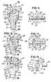
- FIG. 5is a fragmentary plan view of the illustration shown in FIG. 4 ;
- FIG. 6is a fragmentary view similar to FIG. 4 , but showing the receiver rotated approximately 30 degrees about its axis relative to the rod;
- FIG. 7is a fragmentary plan view similar to FIG. 5 and showing the receiver in the position illustrated in FIG. 6 ;
- FIG. 8is fragmentary perspective view showing the receiver in a fully locked position
- FIG. 9is a plan view similar to FIGS. 5 and 7 showing the receiver in a fully locked position
- FIG. 10is a view taken along the line 10 - 10 in FIG. 4 ;
- FIG. 11is a view illustrating the rod after it has been received in the channel of the receiver and supported above a bottom surface of a compression member
- FIG. 12is a sectional view taken along the line 12 - 12 in FIG. 8 ;
- FIG. 13is a fragmentary view showing the rod in cross-section and in a fully locked position
- FIG. 14is a fragmentary view illustrating various features of the locking channels
- FIG. 15is a plan view showing a compression member received in a bore of the receiver and illustrating the aperture through which a tool may be inserted to rotate the screw head before the rod is positioned in a channel of both the receiver and the compression member;
- FIG. 16A-16Eare various views of the receiver in accordance with one illustration of the invention.
- FIG. 17is a sectional view of a compression member in accordance with one illustration of the invention.
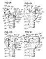
- FIG. 18is a fragmentary sectional view of another illustration of the invention, showing a channel having walls that are generally non-planar to define an intermediate area for loosely capturing the rod;
- FIG. 19is a side elevation view of the embodiment shown in FIG. 18 ;
- FIG. 20is a fragmentary sectional view that has been rotated relative to FIGS. 18 and 19 ;
- FIG. 21is an elevational view rotated relative to FIG. 19 ;
- FIGS. 22-24are plan views illustrating rotational movement of the receiver relative to the rod
- FIGS. 25-27are side elevation views that generally correspond to FIGS. 22-24 , respectively, illustrating the receiver in various positions, but with the rod removed for ease of illustration and understanding;
- FIGS. 28-30are views similar to FIGS. 25-27 , respectively, illustrating the receiver in various rotational positions relative to the rod as the rod is moved from a receiving position to a locked position;
- FIGS. 31-33are fragmentary sectional views somewhat enlarged and diagrammatic to simply illustrate the intermediate capturing step of receiving area for loosely capturing the rod in the receiver.
- FIG. 34is a diagrammatic view which is presented for purposes of illustrating various dimensions of the channels in the receiver or the second illustrative embodiment.
- the assembly 10comprises a screw 12 having a threaded portion 12 a and a head 12 b that in the embodiment being described, has a rounded profile or curvature, as best illustrated in FIGS. 3 and 10 - 13 .
- the screw head 12 bcomprises a hex female opening 12 c for receiving a tool (not shown) for screwing the screw 12 into an aperture 14 a of a spinal bone 14 , such as a vertebra of a spine.
- one feature of the inventionis that it enables a user to fix a relative position of a plurality of vertebrae, such as vertebrae 14 , 16 and 18 in FIG. 1 , in a fixed and stabilized position.
- the assembly 10comprises a retainer or receiver 20 having a generally cylindrical receiver wall 20 c ( FIG. 4 ) that defines an aperture or bore 22 that traverses or extends along a receiver axis A ( FIG. 11 ) the entire length of the receiver 20 , as best illustrated in FIGS. 4 , 10 , and 12 .
- the receiver 20comprises a first end 20 a and a second end 20 b , and although not shown, may comprise a chamfer 21 of about 45 degrees.
- the internal wall 20 cdefines a seat 20 d toward the bottom of the receiver 20 (as viewed in FIGS. 10 and 15 ) that is arcuate or curved in cross section.
- the seat 20 dhas a radius or curved surface R 1 ( FIG. 10 ).
- a diameter or distance D 1 ( FIG. 10 ) of bore 22 at the end 20 b of the receiver or retainer 20is slightly smaller than both a diameter or distance D 2 ( FIGS. 7 and 10 ) of the bore 22 at end 20 a and a diameter D 3 ( FIG. 12 ) of the rounded screw head 12 b so that it defines the receiver seat 20 d ( FIGS. 10 and 15 ) for receiving or capturing the screw head 12 b .
- the screw head 12 bhas an end 12 b 1 that is configured and dimensioned to be received or captured in the seat 20 d and that can be rotated or screwed while in the bore 22 ( FIGS. 10 and 15 ).
- the end 12 b 2has a curved or arcuate shape that generally complements the shape of the seat 20 d to permit polyaxial and relative movement between the receiver 20 and screw 12 .
- the bore 22receives the threaded portion 12 a of the screw 12 until the head 12 b is received in the seat 20 d (as illustrated in FIGS. 10-13 ).
- the seat 20 dcooperates with the end 12 b 1 of head 12 b and permits the retainer or receiver 20 to move polyaxially about a center of head 12 b so that position of the receiver 20 may be altered relative to the head 12 b of screw 12 .
- the rod 24may be any suitable shape in cross section, such as circular, hexagonal, octagonal, polygonal or the like.
- the receiver 20comprises a receiving channel or slot 26 ( FIG. 15 ) defined by wall surfaces 21 a , 21 b , 21 c and 21 d ( FIG. 4 ).
- the receiver 20further comprises a lock, locking means, locking channel, or rotary lock 28 ( FIGS. 11 and 12 ) which is integral with the receiver 20 .
- the receiver 20is manufactured of titanium and is machined to provide the receiving channel 26 , lock 28 and the bore 22 using conventional machining techniques.
- Other potential materialsinclude biocompatible load bearing material, such as metals, metal alloys, carbon fibers, composites, plastics or hybrid materials.
- the lock 28cooperates and is in communication with the receiving channel 26 to provide a continuous channel 30 for receiving the elongated member or rod 24 .
- the lock 28cooperates with the receiving channel 26 and urges rod 24 toward the screw head 12 b and vertebra, such as one of the vertebra 14 - 18 in FIG. 1 , when the receiver 20 is rotated in a clockwise direction (as viewed in FIG. 3 ).
- the continuous channel 30comprises a first channel 32 , the channel 26 , and the second channel 34 .
- the lock 28 and continuous channel 30provides a bayonet-type connection for coupling or fixing the receiver 20 , the rod 24 and screw 12 together in the manner described herein.
- the lock 28comprises the first channel 32 and a second channel 34 ( FIGS. 12 and 13 ) that extend or spiral, as illustrated in FIGS. 16A-16E , about the receiver axis A ( FIG. 11 ) of receiver 20 .
- the first and second channels 32 and 34generally spiral or revolve from the first end 20 a of receiver 20 toward the second end 20 b , as shown in FIGS. 10-13 and 16 A- 16 D.
- the first and second channels 32 and 34are non-linear and spiral or revolve in a general helix about the axis A of the receiver 20 .
- the channels 32 and 34spiral or revolve in the same direction about the axis A, as shown in FIGS. 16A-16D .
- the channels 32 and 34are in communication with both the receiver bore 22 and receiving channel 26 of receiver 20 .
- the channels 32 ( FIG. 11) and 34 ( FIG. 12 )receive the rod 24 after it has been received in channel 26 and urge or force the rod 24 toward the screw head 12 b and vertebra, such as vertebra 14 in FIG. 1 , when the receiver 20 is rotated in a clockwise direction in the illustration being described.
- the first channel 32is defined by a first surface or wall 20 e , a generally opposing second surface or wall 20 g , and a third surface or wall 20 f that joins the walls 20 e and 20 g in the receiver 20 .
- a fourth surface or wall 20 h , a generally opposing fifth surface or wall 20 i , and a sixth surface or wall 20 j that joins walls 20 h and 20 icooperate to define the second channel 34 ( FIGS. 12 and 16D ).
- the walls 20 e and 20 gare generally parallel and walls 20 h and 20 i are generally parallel.
- the walls 20 e and 20 g and 20 h and 20 iare generally planar and have generally constant distance D 4 ( FIGS. 13 ) and D 5 ( FIGS. 11 and 12 ) therebetween.
- the opposing walls 20 e , 20 g , 20 h and 20 imay be non-planar so that the distance or dimensions D 9 and D 10 vary along the length of the channels 32 and 34 .
- the channels 32 and 34generally lay in planes P 1 and P 2 that are at the angles C ( FIG. 14 ) and D, respectively, relative to the axis A of the receiver 20 .
- the walls 20 e and 20 hengage and cam against the rod 24 and force or urge it downward (as viewed in FIGS. 10-15 ) in response to the rotary movement of the receiver 20 .
- the walls 20 e and 20 g and walls 20 h and 20 imay comprise a curved or arcuate area and may cooperate to define an intermediate rod capturing area, as described below relative to FIGS. 18-34 .
- the channel 32is defined by the walls 20 e , 20 f , 20 g and generally curved or arcuate wall portion 50 that couples wall 20 g to surface 21 b ( FIGS. 4 and 16A ) of channel 26 .
- the generally curved arcuate wall portion 50also generally defines an intersection or transition from the receiving channel 26 to the first locking channel 32 of lock 28 .
- the channel 34is defined by 20 h , 20 i and 20 j and a third generally curved or arcuate wall 52 that joins the wall 20 i to wall surface 21 d ( FIGS. 4 and 16C ).
- the wall 52provides an intersection or transition between channel 26 and the second locking channel 34 . Notice that the wall portions 20 f ( FIG.
- FIG. 11) and 20 jalso each have a radius of curvature that generally complements the radius of curvature or circumference of the rod 24 so that when the rod 24 is moved from the unlocked position (illustrated in FIGS. 4 , 5 , 10 and 11 ) to a locked position (illustrated in FIGS. 8 , 9 , 12 and 13 ), the rod 24 is received and positioned against the wall portions 20 f and 20 j as shown.
- the assembly 10may further comprise a compression member 40 ( FIGS. 3 and 17 ).
- the compression member 40comprises a wall 40 a that defines a second generally U-shaped receiving channel 42 .
- the compression member 40also comprises a frusto-conical seat or concave area 41 ( FIGS. 10 and 17 ), defined by a tapered wall or surface 40 b , that engages the rounded shape of the end 12 b 1 ( FIG. 3 ) of screw head 12 b .
- the assembly 10could be provided without the compression member 40 , so that the rod 24 would engage the screw head 12 b directly, for example, when the receiver 20 is rotated as described later herein.
- the compression member 40comprises a length D 6 ( FIGS. 3 and 17 ) and a diameter D 7 ( FIG. 17 ) dimensioned to be received in the bore 22 as shown.
- the channel 42 defined by wall 40 acomprises a bottom surface 40 c .
- the channel 42is generally U-shaped in cross section and has a width or dimension D 8 ( FIGS. 3 , 7 and 17 ) and surface 40 c comprises a radius of curvature R 5 ( FIG. 17 ) that generally complements or is slightly larger than the circumference D 9 ( FIG. 3 ) of the rod 24 .
- the compression member 40is urged downward (as shown in FIGS. 10-13 ) in response to the rotary movement of the receiver 20 .
- the rod 24engages the bottom surface 40 c ( FIGS. 12 and 17 ) of channel 42 of compression member 40 .
- This movementforces and compresses the seat 20 d against the end 12 b 2 of screw head 12 b of the receiver 20 , thereby locking the screw head 12 b to the rod 24 and fixing the relationship of the receiver 20 relative to the screw head 12 b.
- the compression member 40( FIG. 17 ) also comprises a bore or aperture 43 defined by wall 40 d .
- the bore 43has a dimension or diameter D 10 ( FIG. 17 ).
- a surgeon or physicianmay insert a tool, such as a hex head screwdriver (not shown), through channel 26 , through bore 22 of receiver 20 and through the bore 43 and into the hex female opening 12 c ( FIG. 15 ), for example, to tighten or loosen the screw 12 .
- a toolsuch as a hex head screwdriver (not shown)
- FIG. 15it should be understood, as illustrated in FIG. 15 , that the hex female opening 12 c of screw head 12 b is accessible after the screw 12 is inserted through the bone 22 and compression member 40 is situated in the bore 22 .
- the receiving channel 26 ( FIG. 11 ) of receiver 20extends from an end 20 a of receiver 20 in an axial direction and lies in a plane P 3 ( FIG. 15 ) that is generally planar and extends downward along the axis A (as viewed in FIG. 14 ).
- the lock 28 defined by the locking channels 32 and 34revolve, spiral or extend laterally or radially at distances that are generally constant relative to axis A and that vary, such as increase, relative to end 20 a of receiver 20 .
- each of the channels 32 and 34spiral in a general helix downward from the receiving channel 26 and about the axis A of the receiver 20 as shown in FIGS. 10-13 and 16 A- 16 D.
- the channels 32 and 34lay in the planes P 1 and P 2 ( FIG. 14 ), respectively, that intersect axis A at the predetermined angles indicated by double arrows C and D.
- the predetermined angles C and Dare acute angles in the embodiment being described.
- the channel 32is inclined relative to a radial line of receiver 20 at a third angle (indicated by double arrow E in FIG. 16A ) relative to end 20 a .
- Channel 34is also inclined relative to a radial line at a fourth angle F ( FIG. 16B ).
- channels 32 and 34 and the lock 28may be provided, such as channels (not shown) that extend about axis A, but that do not spiral and/or that are not at the inclined angles E and F, such as channels that extend at distances that are generally constant relative to end 20 a.
- the screw 12 , together with receiver 20are screwed into vertebra 14 during which a physician or surgeon screws the threaded portion of screw 12 in the aperture 14 a of the vertebra 14 using a tool (not shown), such as a hex wrench or screwdriver (not shown), that is inserted through channel 26 , bore 22 and bore 43 .
- a toolsuch as a hex wrench or screwdriver (not shown)
- the receiver 20 , screw 12 and compression member 40may be provided in a pre-assembled unit prior to surgery, so no assembly is required by the physician.
- the screw 12is screwed substantially all the way into vertebrae 14 , but is left with space between the receiver 20 and vertebrae 14 so that an angular or polyaxial position of the receiver 20 may be adjusted or changed during the operation.
- the channel 26 of receiver 20 and channel 42 of compression member 40are provided or arranged in a common plane P 3 , as shown in FIGS. 4 , 5 and 15 .
- the surgeonthen places the rod 24 into the channels 26 and 42 and adjusts the multi-axial or polyaxial position of the receiver 20 relative to the rod 24 .
- the channel 26 and bores 22 ( FIG. 10) and 43 ( FIG. 17 )provide a continuous opening or area 49 through which the physician or surgeon may insert a tool, such as a hex tool, to turn, rotate and/or tighten or loosen the screw 12 in the desired direction prior to placing the rod 24 into channel 26 .
- the rod 24remains in an unlocked position.
- the rod 24is supported by and between the arcuate or rounded wall portions 50 and 52 , which causes the rod 24 to be situated above the bottom surface 40 c of the channel 42 of compression member 40 , as illustrated in FIGS. 10 and 11 .
- the arcuate or curved wall portions 50 and 52each comprise a radius of curvatures R 2 ( FIGS. 11 , 14 and 16 a ) and R 3 ( FIGS. 13 and 14 ), respectively, that generally complements or is larger than a radius of curvature or circumference of the rod 24 , as illustrated in FIGS. 11 and 13 .
- the camming or bayonet type action of the rotary lock 28 on receiver 20forces the rod 24 in an axial direction parallel with axis A of receiver 20 when the receiver 20 is turned or rotated with a tool, such as a screwdriver (not shown), placed in channel 26 , as illustrated in FIGS. 6 and 7 .
- This rotary movement or actionforces the rod 24 downward (as viewed in FIG. 10 ) and into the channels 32 and 34 .
- the walls 20 e and 20 g ( FIG. 11 ) of channel 32 and walls 20 h and 20 i ( FIG. 12 ) of channel 34act upon, force or urge the rod 24 downward (as viewed in FIGS.
- the rod 24urges the compression member 40 toward the screw head 12 b and forces wall 40 b of the compression member 40 against the screw head 12 b of screw 12 with a compressive force which causes the screw head 12 b to become fastened or locked to the rod 24 , thereby fixing the receiver 20 and rod 24 to the screw 12 .
- the rod 24engages surfaces 20 e , 20 f , and 20 g of channel 32 and surfaces 20 h , 20 i and 20 j of channel 34 and surface 40 c of second channel 42 .
- the wall 40 d of compression member 40engages screw head 12 b . These surfaces cooperate to retain rod 24 in the locked position.
- the surfaces 20 f and 20 jcomprise a radius of curvature R 4 of about ⁇ .100- ⁇ .130 inch.
- a raised detent portion or bump 59(which is only shown in FIG. 13 for ease of illustration) may be provided in each channel 32 and 34 , as shown in FIG. 13 relative to channel 32 .
- the detent 59is provided to facilitate retaining the rod 24 in the locked position.
- a surgeonmay use one or a plurality of spinal fixation assemblies 10 during a spinal fixation procedure.
- the surgeonmay use a plurality receivers 20 and screws 12 with one rod 24 , as illustrated in FIGS. 1 and 2 .
- the surgeonscrews the screws 12 into a plurality of vertebrae, such as vertebrae 14 , 16 and 18 illustrated in FIG. 1 , and generally aligns the channels 26 of receivers 20 .
- surgeonthen inserts the tool, such as a hex tool (not shown), through bores 22 and 43 and into hex female opening 12 c in screw head 12 b and screws the screw 12 until the bottom 20 b of the receiver 20 engages or is proximately located against its respective vertebra.
- a hex toolsuch as a hex tool (not shown)
- compression member 40is located in each bore 22 of each receiver 20 and generally aligns the channels 42 and 26 , as illustrated in FIGS. 4 , 10 and 15 . It should be understood that when the spinal fixation assembly 10 is in the unlocked position, the channels 26 and 42 are generally parallel or lie in the common plane P 3 as shown in FIG. 15 .
- the rod 24is then placed in channel 26 , whereupon it becomes supported by walls 50 and 52 ( FIG. 4 ) and by wall portions 50 and 52 ( FIGS. 4 and 11 ). This causes rod 24 to be supported slightly above the bottom 40 c of channel 42 of receiver 20 , as mentioned earlier and as illustrated in FIGS. 10 and 11 .
- the surgeonaligns the rod 24 in the receiver 20 to the desired position relative to the spine, vertebrae and other receivers 20 that are being used. He positions the rod 24 and polyaxial or angular position of each receiver(s) 20 relative thereto. It should be understood that the screws and position of the vertebrae, such as vertebrae 14 - 18 , relative to each other may also be adjusted. Once the bones 14 - 18 are adjusted and angular or polyaxial position of each receiver 20 is adjusted, the surgeon locks each receiver 20 to rod 24 by rotating or turning the receiver 20 with a tool, such as a screwdriver (not shown), placed in slot 26 . This causes the receivers 20 to become fixed or locked onto their respective screws 12 and the spinal bones 14 - 18 ( FIG. 1 ) to become aligned and fixed into the desired position.
- a toolsuch as a screwdriver (not shown)
- the surgeonmay tighten one or more screws 12 to a tighter or fixed seated position by situating the tool, such as a hex wrench (not shown), through the aperture 43 ( FIG. 15 ) defined by the wall 40 d of the compression member 40 and into the hexagonal female slot 12 c in the screw head 12 b .
- the surgeonplaces the rod 24 into the channels 26 and 42 ( FIGS. 4 , 5 , 10 and 11 ) of the one or more of the receivers 20 being used.
- the surgeonrotates the receiver 20 about its axis, as illustrated in FIGS. 3 , 6 and 7 using a tool, such as a screwdriver (not shown), in the clockwise direction, as illustrated in FIGS. 6 and 7 .
- a toolsuch as a screwdriver (not shown)
- the compression member 40 and rod 24do not rotate.
- walls 20 e and 20 g ( FIG. 11 ) and walls 20 h and 20 i ( FIG. 12 )urge the rod 24 toward the bottom of channels 32 and 34 and urge the rod 24 to move downward (as viewed in FIGS. 10 and 12 ) toward the surface 40 c or bottom of the channel 42 where it engages the surface 40 c , as illustrated in FIGS. 4-9 and 10 - 13 .
- the rod 24is also supported by and compresses against the surface 40 c of compression member 40 .
- the wall 40 dis caused to engage the screw head 12 b.
- the surgeonrotates the receiver 20 in the clockwise direction, as illustrated in FIGS. 6 and 7 , using the conventional tool, such as a regular screwdriver.
- the receiver 20is rotated until it is moved from the unlocked to the locked position, as illustrated in FIGS. 8 , 9 , 12 and 13 .
- the rod 24is received and engages the walls 20 f and 20 j associated with the ends of channels 32 and 34 , respectively.
- the walls 20 e and 20 hprovide the camming force necessary to cam and urge the rod 24 against the compression member 40 .
- Thiscauses the surface or wall 40 b of compression member 40 to compress and lock against the end portion 12 b 2 ( FIG. 3 ) of screw head 12 b .
- the wall 40 b of compression member 40cooperates with the curved seat 20 d defined by wall 40 b ( FIG. 10 ) and traps or locks the screw head 12 b to the rod 24 .
- the channel 26lies in an imaginary plane that is generally perpendicular to the imaginary plane in which the channel 42 and an axis of rod 24 when the receiver 20 is in the locked position.
- the receiving channel 26is in communication with the channels 32 and 34 of lock 28 and that the lock 28 cooperates with the rod 24 to not only lock the rod 24 to the screw 12 , but also to fix a position of the vertebrae 14 , 16 and 18 .
- the surgeonWhen it is desired to unlock the rod 24 from the screw 12 , the surgeon simply rotates the receiver 20 in a counterclockwise direction in the illustration and reverses the procedure.
- FIGS. 18-34another illustrative embodiment is shown. Those parts that are the same as the parts relative to FIGS. 1-17 have been labeled with the same part number, except that the part numbers in the embodiment described in FIGS. 18-34 have a prime mark (“′”) associated therewith.
- the FIGS. 31-34are diagrammatic enlarged sectional views for ease of illustration.
- the receiver 20 ′comprises channels 32 ′ and 34 ′ that each have a cross-sectional dimension that varies over the length of the channels 32 ′ and 34 ′ to provide an introducing area 60 a where the rod 24 ′ is loosely captured in the channels 32 ′ and 34 ′.
- the channels 32 ′ and 34 ′each have an introducing area 60 a , an intermediate holding or receiving area 60 b and a locking area 60 c .
- the receiving area 60 bwill be described relative to channel 32 ′; however, it should be understood that the channel 34 ′ in the second illustration comprises substantially the same configuration.
- the intermediate area 60 b in the channels 32 ′ and 34 ′enable an intermediate step between initial rod 24 ′ insertion and final rod 24 ′ locking.
- thisis a rod 24 ′ capturing step during which the rod 24 ′ is loosely captured in the receiver 20 ′, but it is not rigidly locked into place against screw 12 ′ yet.
- Thisallows the surgeon greater ease and flexibility when he adjusts the screws 12 ′ position with respect to the rod 24 ′ while the rod 24 ′ is in place.
- the surgeonmay move the screws 12 ′ closer together (compression) or
- the intermediate capturing stepis accomplished by rotating the receiver 20 ′ partially, such as approximately 30 degrees in the illustration as shown in FIGS. 23 , 26 and 29 , which forces the rod 24 ′ from the introducing area 60 a into the intermediate area 60 b.
- the introduction areacomprises an associated dimension D 13 ( FIG. 34 ) and the locking area 60 c has an associated dimension D 14 ( FIG. 34 ).
- the intermediate area 60 bhas an associated intermediate dimension D 15 ( FIG. 34 ) between the wall 62 and wall 64 that is slightly larger than the diameter of the rod 24 ′ and the dimensions D 13 and D 14 associated with the introduction area 60 a and locking area 60 c , respectively. It is dimensioned to accommodate the rod 24 ′ and to capture the rod 24 ′ loosely so that the rod 24 ′ can easily slide between the walls 62 and 64 and is not locked. This facilitates the surgeon adjusting a position of the screws 12 ′ in vertebrae, such as vertebrae 14 ′- 18 ′, relative to a position of the rod 24 .
- the physician or surgeonmay then lock the receiver 20 ′ onto the screw 12 ′ by inserting a tool, such as a screwdriver (not shown), into the slot 26 ′ and rotate the receiver 20 ′ in the clockwise direction as illustrated in FIGS. 22-30 .
- a toolsuch as a screwdriver (not shown)
- the channel 32 ′is defined by a wall 62 , a generally opposing second wall 64 and a joining wall 63 that joins walls 62 and 64 as shown.
- the channel wall 62has a first wall portion 62 a , a second wall portion 62 b and an intermediate wall portion 62 c that couples the wall portions 62 a and 62 b as shown.
- the opposing channel wall 64comprises the first wall portion 64 a , a second wall portion 64 b and an intermediate wall portion 64 c that couples the first and second wall portions 64 a and 64 b as shown.
- intersection 66is defined between the wall portions 64 a and 64 c .
- a second intersection 68is defined between the wall portion 62 b and 62 c as shown.
- the intersections 66 and 68generally define an entrance to the intermediate area 60 .
- the intermediate wall portions 62 c and 64 ccooperate to define the intermediate area 60 b which receives the rod 24 ′ and loosely captures the rod 24 ′ in the receiver 20 ′.
- the channels 32 ′ and 34 ′are configured such that they comprise or define the introduction area 60 a for receiving the rod 24 ′ in the receiver 20 ′, as illustrated in FIGS. 22 , 25 and 28 .
- the first wall portion 64 aprovides a ramp 64 a 1 for directing the rod 24 ′ into the intermediate area 60 b when the receiver 20 ′ is rotated about 20-40 degrees as shown in FIGS. 23 , 26 and 29 .
- the walls 62 and 64are not generally planar and have areas, such as intermediate wall portions 62 c and 64 c that are curved or recessed to facilitate defining the intermediate area 60 b.
- the surgeonmay make the desired adjustments of the rod 24 ′ relative to the screws 12 ′ and vertebrae 14 ′- 18 ′ while the rod 24 ′ is loosely captured in the intermediate area 60 b .
- the surgeonthen uses the tool, such as a screwdriver (not shown), to rotate the receiver 20 ′ to the locked position shown in FIGS. 24 , 27 and 29 .
- the receiver 20 ′urges or forces the rod 24 ′ from the intermediate area 60 b to the locking area 60 c .
- the rod 24 ′becomes situated in the locking area 60 c , whereupon the rod 24 ′ becomes locked therein. Note that the distance or dimension D 12 ( FIG.
- a wall portions 62 , 63 and 64comprises various radii of curvature R 5 -R 9 having the illustrative dimensions or ranges of dimensions set forth in the Table I below.
- the radius of curvature R 8generally corresponds to the cross sectional circumference of the rod 24 ′ so that the rod 24 ′ becomes captured in the locking area 60 c .
- the detent 59FIG. 33 ) may be provided in channels 60 and 62 to further facilitate retaining the rod 24 ′ in the locking area 60 c.
- this system and methodfacilitates providing a locking receiver 20 that reduces or eliminates the need for threading, internally or externally.
- the immediate areas 60 b of channels 32 ′ and 34 ′ of the second embodimentare dimensioned and configured to facilitate locking the rod 24 ′ onto the screws 12 ′ while permitting ease of adjustment between the receiver 20 ′ and the rod 24 ′ when the rod 24 ′ and receiver 20 ′ are situated in the intermediate area 60 b ′, as illustrated in FIGS. 23 , 26 and 29 .
- the rod 24 , screw 12 , receiver 20 and compression member 40are all made of titanium alloy.
- Other materialsmay be used such as metals, metal alloys, carbon fibers, composites, plastics or hybrid materials.
- Various illustrative dimensions or possible ranges of dimensionsare listed in the following Table I:
- the screw 12may have a length D 11 ( FIG. 3 ) ranging from 10 mm-60 mm, and the receiver 20 may have a diameter D 12 ( FIG. 8 ) ranging between 2 mm-10 mm.
- the compression member 40may define the channel 42 having the width D 8 ranging between 2 mm-12 mm.
- the channels 32 and 34may comprise dimensions D 5 , D 6 ( FIGS. 3 and 17 ) ranging between 2 mm-10 mm. It should be understood, however, the other shapes and dimensions may be used without departing from the true spirit and scope of the invention.
- this system and methodprovide a capless multiaxial screw which eliminates the need for caps or screws or threads of the type used in the prior art.
- This system and methodcombine a very simplified yet effective means for locking an elongated member or rod 24 to a screw 12 and spinal bone in the manner described and shown herein.
Landscapes
- Health & Medical Sciences (AREA)
- Orthopedic Medicine & Surgery (AREA)
- Life Sciences & Earth Sciences (AREA)
- Neurology (AREA)
- Surgery (AREA)
- Heart & Thoracic Surgery (AREA)
- Engineering & Computer Science (AREA)
- Biomedical Technology (AREA)
- Nuclear Medicine, Radiotherapy & Molecular Imaging (AREA)
- Medical Informatics (AREA)
- Molecular Biology (AREA)
- Animal Behavior & Ethology (AREA)
- General Health & Medical Sciences (AREA)
- Public Health (AREA)
- Veterinary Medicine (AREA)
- Surgical Instruments (AREA)
Abstract
Description
| Illustrative/Approximate | |||
| Part Number/Label | Dimensions/Ranges | ||
| D1 (FIG. 10) | φ.302 inch | ||
| D2 (FIG. 10) | φ.350 inch | ||
| D3 (FIG. 12) | φ.890 inch | ||
| D4 (FIG. 13) | φ.590 inch | ||
| D5 (FIG. 11) | φ.230 inch | ||
| D6 (FIG. 3) | φ.400 inch | ||
| D7 (FIG. 17) | φ.348 inch | ||
| D8 (FIG. 3) | φ.240 inch | ||
| D9 (FIGS. 3) | φ.218 inch | ||
| D10 (FIG. 17) | φ.200 inch | ||
| D11 (FIG. 3) | 10 mm-60 mm | ||
| D12 (FIG. 8) | 2 mm-10 mm | ||
| D13 (FIG. 34) | φ.225 inch | ||
| D14 (FIG. 34) | φ.220 inch | ||
| D15 (FIG. 34) | φ.210 inch | ||
| R1 (FIG. 10) | φ.115 inch | ||
| R2 (FIG. 14) | φ.340 inch | ||
| R3 (FIG. 14) | φ.340 inch | ||
| R4 (FIG. 12) | φ.100-φ.130 inch | ||
| R5 (FIG. 34) | φ.115 inch | ||
| R6 (FIG. 34) | φ.100 inch | ||
| R7 (FIG. 34) | φ.115 inch-φ.130 inch | ||
| R8 (FIG. 34) | φ.110 inch | ||
| R9 (FIG. 34) | φ.100 inch-φ.130 inch | ||
Claims (59)
Priority Applications (8)
| Application Number | Priority Date | Filing Date | Title |
|---|---|---|---|
| US11/193,523US7717943B2 (en) | 2005-07-29 | 2005-07-29 | Capless multiaxial screw and spinal fixation assembly and method |
| EP06787589AEP1909666B1 (en) | 2005-07-29 | 2006-07-17 | Capless multiaxial screw and spinal fixation assembly |
| PCT/US2006/027699WO2007015811A1 (en) | 2005-07-29 | 2006-07-17 | Capless multiaxial screw and spinal fixation assembly and method |
| JP2008523946AJP2009502322A (en) | 2005-07-29 | 2006-07-17 | Capless multiaxial screw, spinal fixation assembly and method |
| US11/610,698US20070123867A1 (en) | 2005-07-29 | 2006-12-14 | Capless multiaxial screw and spinal fixation assembly and method |
| US12/767,100US8066745B2 (en) | 2005-07-29 | 2010-04-26 | Capless multiaxial screw and spinal fixation assembly and method |
| US13/290,358US8382806B2 (en) | 2005-07-29 | 2011-11-07 | Capless multiaxial screw and spinal fixation assembly and method |
| US13/760,332US20130150893A1 (en) | 2005-07-29 | 2013-02-06 | Capless multiaxial screw and spinal fixation assembly and method |
Applications Claiming Priority (1)
| Application Number | Priority Date | Filing Date | Title |
|---|---|---|---|
| US11/193,523US7717943B2 (en) | 2005-07-29 | 2005-07-29 | Capless multiaxial screw and spinal fixation assembly and method |
Related Child Applications (2)
| Application Number | Title | Priority Date | Filing Date |
|---|---|---|---|
| US11/610,698Continuation-In-PartUS20070123867A1 (en) | 2005-07-29 | 2006-12-14 | Capless multiaxial screw and spinal fixation assembly and method |
| US12/767,100ContinuationUS8066745B2 (en) | 2005-07-29 | 2010-04-26 | Capless multiaxial screw and spinal fixation assembly and method |
Publications (2)
| Publication Number | Publication Date |
|---|---|
| US20070043357A1 US20070043357A1 (en) | 2007-02-22 |
| US7717943B2true US7717943B2 (en) | 2010-05-18 |
Family
ID=37416181
Family Applications (5)
| Application Number | Title | Priority Date | Filing Date |
|---|---|---|---|
| US11/193,523Active2028-04-29US7717943B2 (en) | 2005-07-29 | 2005-07-29 | Capless multiaxial screw and spinal fixation assembly and method |
| US11/610,698AbandonedUS20070123867A1 (en) | 2005-07-29 | 2006-12-14 | Capless multiaxial screw and spinal fixation assembly and method |
| US12/767,100Expired - LifetimeUS8066745B2 (en) | 2005-07-29 | 2010-04-26 | Capless multiaxial screw and spinal fixation assembly and method |
| US13/290,358Expired - LifetimeUS8382806B2 (en) | 2005-07-29 | 2011-11-07 | Capless multiaxial screw and spinal fixation assembly and method |
| US13/760,332AbandonedUS20130150893A1 (en) | 2005-07-29 | 2013-02-06 | Capless multiaxial screw and spinal fixation assembly and method |
Family Applications After (4)
| Application Number | Title | Priority Date | Filing Date |
|---|---|---|---|
| US11/610,698AbandonedUS20070123867A1 (en) | 2005-07-29 | 2006-12-14 | Capless multiaxial screw and spinal fixation assembly and method |
| US12/767,100Expired - LifetimeUS8066745B2 (en) | 2005-07-29 | 2010-04-26 | Capless multiaxial screw and spinal fixation assembly and method |
| US13/290,358Expired - LifetimeUS8382806B2 (en) | 2005-07-29 | 2011-11-07 | Capless multiaxial screw and spinal fixation assembly and method |
| US13/760,332AbandonedUS20130150893A1 (en) | 2005-07-29 | 2013-02-06 | Capless multiaxial screw and spinal fixation assembly and method |
Country Status (4)
| Country | Link |
|---|---|
| US (5) | US7717943B2 (en) |
| EP (1) | EP1909666B1 (en) |
| JP (1) | JP2009502322A (en) |
| WO (1) | WO2007015811A1 (en) |
Cited By (34)
| Publication number | Priority date | Publication date | Assignee | Title |
|---|---|---|---|---|
| US20090306721A1 (en)* | 2008-06-06 | 2009-12-10 | X-Spine Systems, Inc. | Retraction tube for use with capless pedicle screw |
| US20090306719A1 (en)* | 2008-06-06 | 2009-12-10 | Syberspine Limited | Structure and method for driving a pedicle screw with an attached support rod for spinal osteosynthesis |
| US20110152947A1 (en)* | 2009-12-18 | 2011-06-23 | X-Spine Systems, Inc. | Spinal implant locking member with improved guidance, tactile and visual feedback |
| WO2012006216A1 (en) | 2010-07-08 | 2012-01-12 | X-Spine Systems, Inc. | Spinal stabilization system utilizing screw and external facet and/or lamina fixation |
| US8377067B2 (en) | 2004-02-27 | 2013-02-19 | Roger P. Jackson | Orthopedic implant rod reduction tool set and method |
| US8394133B2 (en) | 2004-02-27 | 2013-03-12 | Roger P. Jackson | Dynamic fixation assemblies with inner core and outer coil-like member |
| US8444681B2 (en) | 2009-06-15 | 2013-05-21 | Roger P. Jackson | Polyaxial bone anchor with pop-on shank, friction fit retainer and winged insert |
| US8480714B2 (en) | 2007-12-19 | 2013-07-09 | X-Spine Systems, Inc. | Offset multiaxial or polyaxial screw, system and assembly |
| US8556938B2 (en) | 2009-06-15 | 2013-10-15 | Roger P. Jackson | Polyaxial bone anchor with non-pivotable retainer and pop-on shank, some with friction fit |
| US8814911B2 (en) | 2003-06-18 | 2014-08-26 | Roger P. Jackson | Polyaxial bone screw with cam connection and lock and release insert |
| US8894657B2 (en) | 2004-02-27 | 2014-11-25 | Roger P. Jackson | Tool system for dynamic spinal implants |
| US8911479B2 (en) | 2012-01-10 | 2014-12-16 | Roger P. Jackson | Multi-start closures for open implants |
| US8998959B2 (en) | 2009-06-15 | 2015-04-07 | Roger P Jackson | Polyaxial bone anchors with pop-on shank, fully constrained friction fit retainer and lock and release insert |
| US9050139B2 (en) | 2004-02-27 | 2015-06-09 | Roger P. Jackson | Orthopedic implant rod reduction tool set and method |
| US9168069B2 (en) | 2009-06-15 | 2015-10-27 | Roger P. Jackson | Polyaxial bone anchor with pop-on shank and winged insert with lower skirt for engaging a friction fit retainer |
| WO2015164051A1 (en) | 2014-04-21 | 2015-10-29 | X-Spine Systems, Inc. | Modular multi-axial screw system |
| US9216039B2 (en) | 2004-02-27 | 2015-12-22 | Roger P. Jackson | Dynamic spinal stabilization assemblies, tool set and method |
| US9393047B2 (en) | 2009-06-15 | 2016-07-19 | Roger P. Jackson | Polyaxial bone anchor with pop-on shank and friction fit retainer with low profile edge lock |
| US9480517B2 (en) | 2009-06-15 | 2016-11-01 | Roger P. Jackson | Polyaxial bone anchor with pop-on shank, shank, friction fit retainer, winged insert and low profile edge lock |
| US9629669B2 (en) | 2004-11-23 | 2017-04-25 | Roger P. Jackson | Spinal fixation tool set and method |
| US9743957B2 (en) | 2004-11-10 | 2017-08-29 | Roger P. Jackson | Polyaxial bone screw with shank articulation pressure insert and method |
| US9907574B2 (en) | 2008-08-01 | 2018-03-06 | Roger P. Jackson | Polyaxial bone anchors with pop-on shank, friction fit fully restrained retainer, insert and tool receiving features |
| US9980753B2 (en) | 2009-06-15 | 2018-05-29 | Roger P Jackson | pivotal anchor with snap-in-place insert having rotation blocking extensions |
| US10039578B2 (en) | 2003-12-16 | 2018-08-07 | DePuy Synthes Products, Inc. | Methods and devices for minimally invasive spinal fixation element placement |
| US10039577B2 (en) | 2004-11-23 | 2018-08-07 | Roger P Jackson | Bone anchor receiver with horizontal radiused tool attachment structures and parallel planar outer surfaces |
| US10194951B2 (en) | 2005-05-10 | 2019-02-05 | Roger P. Jackson | Polyaxial bone anchor with compound articulation and pop-on shank |
| US10299839B2 (en) | 2003-12-16 | 2019-05-28 | Medos International Sárl | Percutaneous access devices and bone anchor assemblies |
| US10363070B2 (en) | 2009-06-15 | 2019-07-30 | Roger P. Jackson | Pivotal bone anchor assemblies with pressure inserts and snap on articulating retainers |
| US10687855B2 (en) | 2012-11-21 | 2020-06-23 | Roger P. Jackson | Bone anchor receiver with extension portions having controlled splay allowance helically wound flange forms |
| US10925647B2 (en) | 2000-12-08 | 2021-02-23 | Roger P. Jackson | Threaded closure with inwardly-facing tool engaging concave radiused structures and axial through-aperture |
| US11147591B2 (en) | 2004-11-10 | 2021-10-19 | Roger P Jackson | Pivotal bone anchor receiver assembly with threaded closure |
| US11224464B2 (en) | 2002-05-09 | 2022-01-18 | Roger P. Jackson | Threaded closure with inwardly-facing tool engaging concave radiused structures and axial through-aperture |
| US11419642B2 (en) | 2003-12-16 | 2022-08-23 | Medos International Sarl | Percutaneous access devices and bone anchor assemblies |
| US12383311B2 (en) | 2010-05-14 | 2025-08-12 | Roger P. Jackson | Pivotal bone anchor assembly and method for use thereof |
Families Citing this family (96)
| Publication number | Priority date | Publication date | Assignee | Title |
|---|---|---|---|---|
| US20160242816A9 (en)* | 2001-05-09 | 2016-08-25 | Roger P. Jackson | Dynamic spinal stabilization assembly with elastic bumpers and locking limited travel closure mechanisms |
| US8292926B2 (en) | 2005-09-30 | 2012-10-23 | Jackson Roger P | Dynamic stabilization connecting member with elastic core and outer sleeve |
| US10729469B2 (en)* | 2006-01-09 | 2020-08-04 | Roger P. Jackson | Flexible spinal stabilization assembly with spacer having off-axis core member |
| US10258382B2 (en)* | 2007-01-18 | 2019-04-16 | Roger P. Jackson | Rod-cord dynamic connection assemblies with slidable bone anchor attachment members along the cord |
| US8353932B2 (en) | 2005-09-30 | 2013-01-15 | Jackson Roger P | Polyaxial bone anchor assembly with one-piece closure, pressure insert and plastic elongate member |
| WO2006052796A2 (en) | 2004-11-10 | 2006-05-18 | Jackson Roger P | Helical guide and advancement flange with break-off extensions |
| US8876868B2 (en) | 2002-09-06 | 2014-11-04 | Roger P. Jackson | Helical guide and advancement flange with radially loaded lip |
| US6716214B1 (en) | 2003-06-18 | 2004-04-06 | Roger P. Jackson | Polyaxial bone screw with spline capture connection |
| US7377923B2 (en) | 2003-05-22 | 2008-05-27 | Alphatec Spine, Inc. | Variable angle spinal screw assembly |
| US8137386B2 (en) | 2003-08-28 | 2012-03-20 | Jackson Roger P | Polyaxial bone screw apparatus |
| US7967850B2 (en) | 2003-06-18 | 2011-06-28 | Jackson Roger P | Polyaxial bone anchor with helical capture connection, insert and dual locking assembly |
| US8926670B2 (en) | 2003-06-18 | 2015-01-06 | Roger P. Jackson | Polyaxial bone screw assembly |
| US8398682B2 (en) | 2003-06-18 | 2013-03-19 | Roger P. Jackson | Polyaxial bone screw assembly |
| US8377102B2 (en) | 2003-06-18 | 2013-02-19 | Roger P. Jackson | Polyaxial bone anchor with spline capture connection and lower pressure insert |
| US8257398B2 (en) | 2003-06-18 | 2012-09-04 | Jackson Roger P | Polyaxial bone screw with cam capture |
| US11241261B2 (en) | 2005-09-30 | 2022-02-08 | Roger P Jackson | Apparatus and method for soft spinal stabilization using a tensionable cord and releasable end structure |
| US7651502B2 (en) | 2004-09-24 | 2010-01-26 | Jackson Roger P | Spinal fixation tool set and method for rod reduction and fastener insertion |
| WO2006047711A2 (en) | 2004-10-25 | 2006-05-04 | Alphaspine, Inc. | Pedicle screw systems and methods |
| US7604655B2 (en)* | 2004-10-25 | 2009-10-20 | X-Spine Systems, Inc. | Bone fixation system and method for using the same |
| US8926672B2 (en) | 2004-11-10 | 2015-01-06 | Roger P. Jackson | Splay control closure for open bone anchor |
| US7875065B2 (en)* | 2004-11-23 | 2011-01-25 | Jackson Roger P | Polyaxial bone screw with multi-part shank retainer and pressure insert |
| US9216041B2 (en) | 2009-06-15 | 2015-12-22 | Roger P. Jackson | Spinal connecting members with tensioned cords and rigid sleeves for engaging compression inserts |
| US8308782B2 (en) | 2004-11-23 | 2012-11-13 | Jackson Roger P | Bone anchors with longitudinal connecting member engaging inserts and closures for fixation and optional angulation |
| WO2006057837A1 (en) | 2004-11-23 | 2006-06-01 | Jackson Roger P | Spinal fixation tool attachment structure |
| WO2006058221A2 (en) | 2004-11-24 | 2006-06-01 | Abdou Samy M | Devices and methods for inter-vertebral orthopedic device placement |
| AU2006214001B2 (en) | 2005-02-18 | 2011-05-26 | Samy Abdou | Devices and methods for dynamic fixation of skeletal structure |
| US10076361B2 (en) | 2005-02-22 | 2018-09-18 | Roger P. Jackson | Polyaxial bone screw with spherical capture, compression and alignment and retention structures |
| US7901437B2 (en) | 2007-01-26 | 2011-03-08 | Jackson Roger P | Dynamic stabilization member with molded connection |
| US7717943B2 (en) | 2005-07-29 | 2010-05-18 | X-Spine Systems, Inc. | Capless multiaxial screw and spinal fixation assembly and method |
| US7909830B2 (en)* | 2005-08-25 | 2011-03-22 | Synthes Usa, Llc | Methods of spinal fixation and instrumentation |
| US20080140076A1 (en)* | 2005-09-30 | 2008-06-12 | Jackson Roger P | Dynamic stabilization connecting member with slitted segment and surrounding external elastomer |
| US8105368B2 (en) | 2005-09-30 | 2012-01-31 | Jackson Roger P | Dynamic stabilization connecting member with slitted core and outer sleeve |
| WO2007041702A2 (en) | 2005-10-04 | 2007-04-12 | Alphaspine, Inc. | Pedicle screw system with provisional locking aspects |
| US8097025B2 (en)* | 2005-10-25 | 2012-01-17 | X-Spine Systems, Inc. | Pedicle screw system configured to receive a straight or curved rod |
| US7575587B2 (en)* | 2005-12-30 | 2009-08-18 | Warsaw Orthopedic, Inc. | Top-tightening side-locking spinal connector assembly |
| US7722652B2 (en) | 2006-01-27 | 2010-05-25 | Warsaw Orthopedic, Inc. | Pivoting joints for spinal implants including designed resistance to motion and methods of use |
| US8057519B2 (en)* | 2006-01-27 | 2011-11-15 | Warsaw Orthopedic, Inc. | Multi-axial screw assembly |
| US7833252B2 (en) | 2006-01-27 | 2010-11-16 | Warsaw Orthopedic, Inc. | Pivoting joints for spinal implants including designed resistance to motion and methods of use |
| WO2008008511A2 (en)* | 2006-07-14 | 2008-01-17 | Laszlo Garamszegi | Pedicle screw assembly with inclined surface seat |
| WO2008024373A2 (en)* | 2006-08-21 | 2008-02-28 | Abdou M Samy | Bone screw systems and methods of use |
| US7988711B2 (en)* | 2006-09-21 | 2011-08-02 | Warsaw Orthopedic, Inc. | Low profile vertebral stabilization systems and methods |
| US8366745B2 (en)* | 2007-05-01 | 2013-02-05 | Jackson Roger P | Dynamic stabilization assembly having pre-compressed spacers with differential displacements |
| US8475498B2 (en)* | 2007-01-18 | 2013-07-02 | Roger P. Jackson | Dynamic stabilization connecting member with cord connection |
| US10383660B2 (en) | 2007-05-01 | 2019-08-20 | Roger P. Jackson | Soft stabilization assemblies with pretensioned cords |
| US8366714B2 (en)* | 2007-10-23 | 2013-02-05 | K2M, Inc. | Rod insertion instrument and method of use |
| US20090105756A1 (en)* | 2007-10-23 | 2009-04-23 | Marc Richelsoph | Spinal implant |
| US8007522B2 (en) | 2008-02-04 | 2011-08-30 | Depuy Spine, Inc. | Methods for correction of spinal deformities |
| US20100004693A1 (en)* | 2008-07-01 | 2010-01-07 | Peter Thomas Miller | Cam locking spine stabilization system and method |
| US8118837B2 (en)* | 2008-07-03 | 2012-02-21 | Zimmer Spine, Inc. | Tapered-lock spinal rod connectors and methods for use |
| US8197512B1 (en) | 2008-07-16 | 2012-06-12 | Zimmer Spine, Inc. | System and method for spine stabilization using resilient inserts |
| US8167914B1 (en) | 2008-07-16 | 2012-05-01 | Zimmer Spine, Inc. | Locking insert for spine stabilization and method of use |
| US8343228B2 (en)* | 2008-09-03 | 2013-01-01 | The Cleveland Clinic Foundation | Arthroplastic implant with anchor peg for basilar joint and related methods |
| US8231625B2 (en)* | 2008-09-03 | 2012-07-31 | The Cleveland Clinic Foundation | Modular bone fixation device for treatment of fractures and related methods |
| US8506641B2 (en)* | 2008-09-03 | 2013-08-13 | The Cleveland Clinic Foundation | Arthrodesis implant for finger joints and related methods |
| US8167952B2 (en)* | 2008-09-03 | 2012-05-01 | The Cleveland Clinic Foundation | Arthroplastic implant with shield for basilar joint and related methods |
| US9603629B2 (en) | 2008-09-09 | 2017-03-28 | Intelligent Implant Systems Llc | Polyaxial screw assembly |
| US11229457B2 (en) | 2009-06-15 | 2022-01-25 | Roger P. Jackson | Pivotal bone anchor assembly with insert tool deployment |
| US9668771B2 (en) | 2009-06-15 | 2017-06-06 | Roger P Jackson | Soft stabilization assemblies with off-set connector |
| US8764806B2 (en) | 2009-12-07 | 2014-07-01 | Samy Abdou | Devices and methods for minimally invasive spinal stabilization and instrumentation |
| AU2011299558A1 (en) | 2010-09-08 | 2013-05-02 | Roger P. Jackson | Dynamic stabilization members with elastic and inelastic sections |
| US9295501B2 (en)* | 2011-08-02 | 2016-03-29 | Blackstone Medical, Inc. | Bayonet counter-torque wrench |
| US8845728B1 (en) | 2011-09-23 | 2014-09-30 | Samy Abdou | Spinal fixation devices and methods of use |
| US8740950B2 (en) | 2011-12-08 | 2014-06-03 | Spine Wave, Inc. | Methods for percutaneously attaching a cross connector to contralateral spinal constructs |
| US20130226240A1 (en) | 2012-02-22 | 2013-08-29 | Samy Abdou | Spinous process fixation devices and methods of use |
| US9198767B2 (en) | 2012-08-28 | 2015-12-01 | Samy Abdou | Devices and methods for spinal stabilization and instrumentation |
| US9782204B2 (en) | 2012-09-28 | 2017-10-10 | Medos International Sarl | Bone anchor assemblies |
| US9320617B2 (en) | 2012-10-22 | 2016-04-26 | Cogent Spine, LLC | Devices and methods for spinal stabilization and instrumentation |
| US10058354B2 (en) | 2013-01-28 | 2018-08-28 | Roger P. Jackson | Pivotal bone anchor assembly with frictional shank head seating surfaces |
| US8852239B2 (en) | 2013-02-15 | 2014-10-07 | Roger P Jackson | Sagittal angle screw with integral shank and receiver |
| US20140277153A1 (en) | 2013-03-14 | 2014-09-18 | DePuy Synthes Products, LLC | Bone Anchor Assemblies and Methods With Improved Locking |
| US9724145B2 (en) | 2013-03-14 | 2017-08-08 | Medos International Sarl | Bone anchor assemblies with multiple component bottom loading bone anchors |
| US9259247B2 (en) | 2013-03-14 | 2016-02-16 | Medos International Sarl | Locking compression members for use with bone anchor assemblies and methods |
| US10342582B2 (en) | 2013-03-14 | 2019-07-09 | DePuy Synthes Products, Inc. | Bone anchor assemblies and methods with improved locking |
| US9775660B2 (en) | 2013-03-14 | 2017-10-03 | DePuy Synthes Products, Inc. | Bottom-loading bone anchor assemblies and methods |
| CN106659524B (en)* | 2013-06-07 | 2019-02-12 | 乔治·弗雷 | Patient-matched instrument and method for performing surgical procedures |
| WO2015023651A1 (en)* | 2013-08-12 | 2015-02-19 | Alphatec Spine, Inc. | Blade attachment and adjustment mechanism for tissue retraction |
| US9526529B2 (en) | 2013-09-25 | 2016-12-27 | Blackstone Medical, Inc. | Bone screw systems with pressure caps having biasing members |
| US9044273B2 (en) | 2013-10-07 | 2015-06-02 | Intelligent Implant Systems, Llc | Polyaxial plate rod system and surgical procedure |
| US9480501B2 (en) | 2013-10-21 | 2016-11-01 | Blackstone Medical, Inc. | Modular pedicle screw |
| US9566092B2 (en) | 2013-10-29 | 2017-02-14 | Roger P. Jackson | Cervical bone anchor with collet retainer and outer locking sleeve |
| US9980758B2 (en) | 2013-11-27 | 2018-05-29 | Blackstone Medical, Inc. | Minimally invasive counter-torque wrench system |
| US9717533B2 (en) | 2013-12-12 | 2017-08-01 | Roger P. Jackson | Bone anchor closure pivot-splay control flange form guide and advancement structure |
| US9451993B2 (en) | 2014-01-09 | 2016-09-27 | Roger P. Jackson | Bi-radial pop-on cervical bone anchor |
| US10064658B2 (en) | 2014-06-04 | 2018-09-04 | Roger P. Jackson | Polyaxial bone anchor with insert guides |
| US9597119B2 (en) | 2014-06-04 | 2017-03-21 | Roger P. Jackson | Polyaxial bone anchor with polymer sleeve |
| US20160213405A1 (en) | 2015-01-27 | 2016-07-28 | K2M, Inc. | Vertebral plate systems and methods of use |
| US10028841B2 (en) | 2015-01-27 | 2018-07-24 | K2M, Inc. | Interbody spacer |
| EP3361999A4 (en)* | 2015-10-13 | 2019-06-26 | K2M, Inc. | Interbody spacer |
| US10857003B1 (en) | 2015-10-14 | 2020-12-08 | Samy Abdou | Devices and methods for vertebral stabilization |
| US10744000B1 (en) | 2016-10-25 | 2020-08-18 | Samy Abdou | Devices and methods for vertebral bone realignment |
| US10973648B1 (en) | 2016-10-25 | 2021-04-13 | Samy Abdou | Devices and methods for vertebral bone realignment |
| US9763700B1 (en)* | 2016-12-14 | 2017-09-19 | Spine Wave, Inc. | Polyaxial bone screw |
| US10610265B1 (en) | 2017-07-31 | 2020-04-07 | K2M, Inc. | Polyaxial bone screw with increased angulation |
| US11179248B2 (en) | 2018-10-02 | 2021-11-23 | Samy Abdou | Devices and methods for spinal implantation |
| WO2022184797A1 (en) | 2021-03-05 | 2022-09-09 | Medos International Sarl | Selectively locking polyaxial screw |
| EP4111992B1 (en)* | 2021-07-01 | 2024-01-31 | Biedermann Technologies GmbH & Co. KG | Bone anchoring device |
Citations (184)
| Publication number | Priority date | Publication date | Assignee | Title |
|---|---|---|---|---|
| US483342A (en) | 1892-09-27 | bolte | ||
| US900717A (en) | 1907-09-26 | 1908-10-13 | Edward B Feaster | Cable fastener or clamp. |
| GB167228A (en) | 1920-04-26 | 1921-07-26 | Stanley Watkin Darker | Improvements in or relating to nut locks |
| US2344381A (en) | 1940-05-03 | 1944-03-14 | Leonard A Young | Nut |
| US3019504A (en) | 1959-04-29 | 1962-02-06 | Burroughs Corp | Tape and terminal fitting assembly |
| US3648691A (en) | 1970-02-24 | 1972-03-14 | Univ Colorado State Res Found | Method of applying vertebral appliance |
| US3752203A (en) | 1971-07-28 | 1973-08-14 | Hill Fastener Corp | Lock-screw fasteners |
| US3851601A (en) | 1973-02-09 | 1974-12-03 | J Davis | Display case stand |
| US3875936A (en) | 1972-12-18 | 1975-04-08 | Robert G Volz | Trochantaric attachment assembly and method of using same |
| US4011602A (en) | 1975-10-06 | 1977-03-15 | Battelle Memorial Institute | Porous expandable device for attachment to bone tissue |
| US4085744A (en) | 1977-01-31 | 1978-04-25 | David Warren Lewis | Spinal column prostheses orthoses |
| US4269178A (en) | 1979-06-04 | 1981-05-26 | Keene James S | Hook assembly for engaging a spinal column |
| US4289124A (en) | 1978-09-18 | 1981-09-15 | Zickel Robert E | Surgical appliance for the fixation of fractured bones |
| US4294300A (en) | 1978-01-13 | 1981-10-13 | Nedschroef Octrooi Maatschappij N.V. | Self-locking fastener |
| US4309139A (en) | 1979-07-29 | 1982-01-05 | Kishu Neji Co., Ltd. | Self-locking fastening device |
| US4411259A (en) | 1980-02-04 | 1983-10-25 | Drummond Denis S | Apparatus for engaging a hook assembly to a spinal column |
| US4604995A (en) | 1984-03-30 | 1986-08-12 | Stephens David C | Spinal stabilizer |
| US4611581A (en) | 1983-12-16 | 1986-09-16 | Acromed Corporation | Apparatus for straightening spinal columns |
| US4611580A (en) | 1983-11-23 | 1986-09-16 | Henry Ford Hospital | Intervertebral body stabilization |
| US4641636A (en) | 1983-05-04 | 1987-02-10 | Cotrel Yves P C A | Device for supporting the rachis |
| US4648388A (en) | 1985-11-01 | 1987-03-10 | Acromed Corporation | Apparatus and method for maintaining vertebrae in a desired relationship |
| US4653481A (en) | 1985-07-24 | 1987-03-31 | Howland Robert S | Advanced spine fixation system and method |
| US4655199A (en) | 1985-03-29 | 1987-04-07 | Acromed Corporation | Spinal column straightening apparatus |
| US4658809A (en) | 1983-02-25 | 1987-04-21 | Firma Heinrich C. Ulrich | Implantable spinal distraction splint |
| US4696290A (en) | 1983-12-16 | 1987-09-29 | Acromed Corporation | Apparatus for straightening spinal columns |
| GB2173104B (en) | 1984-02-28 | 1987-11-25 | Peter John Webb | Spinal fixation apparatus |
| US4719905A (en) | 1985-11-01 | 1988-01-19 | Acromed Corporation | Apparatus and method for maintaining vertebrae in a desired relationship |
| DE3219575C2 (en) | 1982-05-25 | 1988-02-18 | Patrick Dr.Med. 3590 Bad Wildungen De Kluger | |
| DE3711013C1 (en) | 1987-04-01 | 1988-06-09 | Harms Juergen | Pedicle screw |
| US4771767A (en) | 1986-02-03 | 1988-09-20 | Acromed Corporation | Apparatus and method for maintaining vertebrae in a desired relationship |
| US4805602A (en) | 1986-11-03 | 1989-02-21 | Danninger Medical Technology | Transpedicular screw and rod system |
| FR2615095B1 (en) | 1987-05-15 | 1989-08-18 | Fabrication Materiel Orthopedi | OSTEOSYNTHESIS INSTRUMENTATION FOR THE CORRECTION OF LUMBAR SCOLIOSES BY POSTERIOR PATHWAY |
| US4887595A (en) | 1987-07-29 | 1989-12-19 | Acromed Corporation | Surgically implantable device for spinal columns |
| US4887596A (en) | 1988-03-02 | 1989-12-19 | Synthes (U.S.A.) | Open backed pedicle screw |
| US4913134A (en) | 1987-07-24 | 1990-04-03 | Biotechnology, Inc. | Spinal fixation system |
| US4946458A (en) | 1986-04-25 | 1990-08-07 | Harms Juergen | Pedicle screw |
| US4950269A (en) | 1988-06-13 | 1990-08-21 | Acromed Corporation | Spinal column fixation device |
| EP0242705B1 (en) | 1986-04-18 | 1990-11-07 | Hünnebeck-RöRo Gesellschaft mit beschränkter Haftung | Steel tube shore with quick lowering |
| US5005562A (en) | 1988-06-24 | 1991-04-09 | Societe De Fabrication De Material Orthopedique | Implant for spinal osteosynthesis device, in particular in traumatology |
| US5024213A (en) | 1989-02-08 | 1991-06-18 | Acromed Corporation | Connector for a corrective device |
| US5042982A (en) | 1987-07-08 | 1991-08-27 | Harms Juergen | Positioning device |
| US5067955A (en) | 1989-04-13 | 1991-11-26 | Societe De Fabrication De Material Orthopedique | Vertebral implant for osteosynthesis device |
| US5084049A (en) | 1989-02-08 | 1992-01-28 | Acromed Corporation | Transverse connector for spinal column corrective devices |
| US5092867A (en) | 1988-07-13 | 1992-03-03 | Harms Juergen | Correction and supporting apparatus, in particular for the spinal column |
| US5113685A (en) | 1991-01-28 | 1992-05-19 | Acromed Corporation | Apparatus for contouring spine plates and/or rods |
| US5120171A (en) | 1990-11-27 | 1992-06-09 | Stuart Surgical | Bone screw with improved threads |
| US5127912A (en) | 1990-10-05 | 1992-07-07 | R. Charles Ray | Sacral implant system |
| US5129900A (en) | 1990-07-24 | 1992-07-14 | Acromed Corporation | Spinal column retaining method and apparatus |
| US5176680A (en) | 1990-02-08 | 1993-01-05 | Vignaud Jean Louis | Device for the adjustable fixing of spinal osteosynthesis rods |
| US5183359A (en) | 1992-05-12 | 1993-02-02 | Illinois Tool Works Inc. | Rotary fastener with anti-strip-out nibs |
| US5190543A (en) | 1990-11-26 | 1993-03-02 | Synthes (U.S.A.) | Anchoring device |
| US5207678A (en) | 1989-07-20 | 1993-05-04 | Prufer | Pedicle screw and receiver member therefore |
| US5246303A (en) | 1989-06-05 | 1993-09-21 | Pujol Y Tarrago, S.A. | Connector device for metal cables |
| US5257993A (en) | 1991-10-04 | 1993-11-02 | Acromed Corporation | Top-entry rod retainer |
| US5261913A (en) | 1989-07-26 | 1993-11-16 | J.B.S. Limited Company | Device for straightening, securing, compressing and elongating the spinal column |
| FR2624720B1 (en) | 1987-12-21 | 1994-04-15 | Fabrication Materiel Orthopediqu | IMPLANT FOR OSTEOSYNTHESIS DEVICE, ESPECIALLY OF THE RACHIS |
| DE9403231U1 (en) | 1994-02-26 | 1994-04-21 | Aesculap Ag, 78532 Tuttlingen | Surgical implant |
| US5312402A (en)* | 1991-04-16 | 1994-05-17 | Synthes (U.S.A.) | Connection device |
| US5360431A (en) | 1990-04-26 | 1994-11-01 | Cross Medical Products | Transpedicular screw system and method of use |
| FR2706762A1 (en) | 1993-06-25 | 1994-12-30 | Landanger Landos | Pedicle screw for vertebral guide rod |
| US5380325A (en) | 1992-11-06 | 1995-01-10 | Biomat | Osteosynthesis device for spinal consolidation |
| US5466237A (en) | 1993-11-19 | 1995-11-14 | Cross Medical Products, Inc. | Variable locking stabilizer anchor seat and screw |
| US5520689A (en)* | 1992-06-04 | 1996-05-28 | Synthes (U.S.A.) | Osteosynthetic fastening device |
| US5534001A (en) | 1993-05-11 | 1996-07-09 | Synthes (U.S.A.) | Osteosynthetic fixation element and manipulation device |
| US5549608A (en) | 1995-07-13 | 1996-08-27 | Fastenetix, L.L.C. | Advanced polyaxial locking screw and coupling element device for use with rod fixation apparatus |
| US5562663A (en) | 1995-06-07 | 1996-10-08 | Danek Medical, Inc. | Implant interconnection mechanism |
| US5603714A (en)* | 1993-12-15 | 1997-02-18 | Mizuho Ika Kogyo Kabushiki Kaisha | Instrument for anterior correction of scoliosis or the like |
| US5609593A (en) | 1995-07-13 | 1997-03-11 | Fastenetix, Llc | Advanced polyaxial locking hook and coupling element device for use with top loading rod fixation devices |
| US5647873A (en) | 1995-04-13 | 1997-07-15 | Fastenetix, L.L.C. | Bicentric polyaxial locking screw and coupling element |
| US5667508A (en) | 1996-05-01 | 1997-09-16 | Fastenetix, Llc | Unitary locking cap for use with a pedicle screw |
| US5669911A (en) | 1995-04-13 | 1997-09-23 | Fastenetix, L.L.C. | Polyaxial pedicle screw |
| DE3639810C2 (en) | 1986-11-21 | 1998-04-09 | Heinrich Ulrich | Implant for spine correction and / or stabilization |
| US5797911A (en) | 1996-09-24 | 1998-08-25 | Sdgi Holdings, Inc. | Multi-axial bone screw assembly |
| US5879350A (en) | 1996-09-24 | 1999-03-09 | Sdgi Holdings, Inc. | Multi-axial bone screw assembly |
| US5882350A (en) | 1995-04-13 | 1999-03-16 | Fastenetix, Llc | Polyaxial pedicle screw having a threaded and tapered compression locking mechanism |
| US5885286A (en) | 1996-09-24 | 1999-03-23 | Sdgi Holdings, Inc. | Multi-axial bone screw assembly |
| US5891145A (en) | 1997-07-14 | 1999-04-06 | Sdgi Holdings, Inc. | Multi-axial screw |
| US5954725A (en) | 1996-11-07 | 1999-09-21 | Sdgi Holdings, Inc. | Multi-angle bone screw assembly using shape memory technology |
| US6010503A (en) | 1998-04-03 | 2000-01-04 | Spinal Innovations, Llc | Locking mechanism |
| US6063090A (en) | 1996-12-12 | 2000-05-16 | Synthes (U.S.A.) | Device for connecting a longitudinal support to a pedicle screw |
| US6077262A (en) | 1993-06-04 | 2000-06-20 | Synthes (U.S.A.) | Posterior spinal implant |
| US6090111A (en) | 1998-06-17 | 2000-07-18 | Surgical Dynamics, Inc. | Device for securing spinal rods |
| US6113601A (en) | 1998-06-12 | 2000-09-05 | Bones Consulting, Llc | Polyaxial pedicle screw having a loosely coupled locking cap |
| US6132432A (en) | 1996-10-18 | 2000-10-17 | Spinal Innovations Llc | Spinal implant fixation assembly |
| US6235033B1 (en) | 2000-04-19 | 2001-05-22 | Synthes (Usa) | Bone fixation assembly |
| US6280442B1 (en) | 1999-09-01 | 2001-08-28 | Sdgi Holdings, Inc. | Multi-axial bone screw assembly |
| US6302888B1 (en) | 1999-03-19 | 2001-10-16 | Interpore Cross International | Locking dovetail and self-limiting set screw assembly for a spinal stabilization member |
| US20020013585A1 (en) | 2000-06-30 | 2002-01-31 | Jose Gournay | Spinal implant for an osteosynthesis device |
| EP1190678A2 (en) | 2000-09-22 | 2002-03-27 | DePuy Acromed, Inc. | Lock cap anchor assembly for orthopaedic fixation |
| US6371957B1 (en) | 1997-01-22 | 2002-04-16 | Synthes (Usa) | Device for connecting a longitudinal bar to a pedicle screw |
| EP1210914A1 (en) | 1999-08-05 | 2002-06-05 | Traiber, S.A. | Intervertebral fixing system used in treatments of the spinal column |
| US6402752B2 (en) | 2000-02-07 | 2002-06-11 | Ulrich Gmbh & Co. Kg | Polyaxial pedicle-screw |
| US20020082601A1 (en)* | 2000-12-27 | 2002-06-27 | Yoshiaki Toyama | Vertebra correcting and fixing device |
| US20020091386A1 (en) | 2001-01-05 | 2002-07-11 | Greg Martin | Pedicle screw assembly |
| US20020111626A1 (en) | 2001-02-15 | 2002-08-15 | Ralph James D. | Polyaxial pedicle screw having a rotating locking element |
| US20020120272A1 (en) | 1998-06-17 | 2002-08-29 | Hansen Yuan | Device for securing spinal rods |
| US20020133158A1 (en) | 2001-03-15 | 2002-09-19 | Saint Martin Pierre Henri | Anchoring member with packer |
| US20020133154A1 (en) | 2001-03-15 | 2002-09-19 | Saint Martin Pierre Henri | Anchoring member with safety ring |
| US20020143341A1 (en) | 2001-03-27 | 2002-10-03 | Lutz Biedermann | Anchoring element |
| WO2002080788A1 (en)* | 2001-04-06 | 2002-10-17 | Ldr Medical | Spinal osteosynthesis device and preparation method |
| US20030032957A1 (en) | 2001-08-13 | 2003-02-13 | Mckinley Laurence M. | Vertebral alignment and fixation assembly |
| US20030073996A1 (en) | 2001-10-17 | 2003-04-17 | Doubler Robert L. | Split ring bone screw for a spinal fixation system |
| US20030078583A1 (en) | 2001-10-23 | 2003-04-24 | Biedermann Motech Gmbh | Bone fixing device |
| US6626908B2 (en) | 2000-07-22 | 2003-09-30 | Corin Spinal Systems Limited | Pedicle attachment assembly |
| US20030187433A1 (en) | 2002-01-17 | 2003-10-02 | A-Spine Inc. | Rotary device for fixing vertebrae under treatment |
| US20030187434A1 (en) | 2002-01-24 | 2003-10-02 | A-Spine Inc. | Rotary device for fixing spinal column under treatment |
| WO2003086204A2 (en) | 2002-04-09 | 2003-10-23 | Neville Alleyne | Bone fixation apparatus |
| US20030199873A1 (en)* | 2002-04-18 | 2003-10-23 | Marc Richelsoph | Screw and rod fixation assembly and device |
| US6652526B1 (en) | 2001-10-05 | 2003-11-25 | Ruben P. Arafiles | Spinal stabilization rod fastener |
| US20040039383A1 (en) | 2002-08-26 | 2004-02-26 | Jackson Roger P | Nested closure plug and set screw with break-off heads |
| US20040039384A1 (en)* | 2002-08-21 | 2004-02-26 | Boehm Frank H. | Device and method for pertcutaneous placement of lumbar pedicle screws and connecting rods |
| US20040049190A1 (en) | 2002-08-09 | 2004-03-11 | Biedermann Motech Gmbh | Dynamic stabilization device for bones, in particular for vertebrae |
| US6716214B1 (en) | 2003-06-18 | 2004-04-06 | Roger P. Jackson | Polyaxial bone screw with spline capture connection |
| US20040097933A1 (en) | 2002-11-19 | 2004-05-20 | Rodolphe Lourdel | Vertebral anchoring device and its blocking device on a polyaxial screw |
| US20040127896A1 (en) | 2002-10-28 | 2004-07-01 | Alan Lombardo | Bone plate assembly provided with screw locking mechanisms |
| US20040138662A1 (en) | 2002-10-30 | 2004-07-15 | Landry Michael E. | Spinal stabilization systems and methods |
| US20040153068A1 (en) | 2003-02-05 | 2004-08-05 | Pioneer Laboratories, Inc. | Low profile spinal fixation system |
| US6793657B2 (en) | 2001-09-10 | 2004-09-21 | Solco Biomedical Co., Ltd. | Spine fixing apparatus |
| FR2852815A1 (en) | 2003-03-26 | 2004-10-01 | Jean Pierre Lenfant | Inter-vertebral connecting device for use in e.g. scoliosis, has two pedicle screws, coupled by rod, including V-shaped head with two branches, where branches are tightened to turn rod by ninety degrees |
| US6802844B2 (en) | 2001-03-26 | 2004-10-12 | Nuvasive, Inc | Spinal alignment apparatus and methods |
| WO2004089245A2 (en) | 2003-04-04 | 2004-10-21 | Theken Surgical, Llc | Bone anchor |
| US20040236330A1 (en) | 2003-05-22 | 2004-11-25 | Thomas Purcell | Variable angle spinal screw assembly |
| US20040267264A1 (en) | 2003-06-27 | 2004-12-30 | Konieczynski David D. | Polyaxial bone screw |
| US6843791B2 (en) | 2003-01-10 | 2005-01-18 | Depuy Acromed, Inc. | Locking cap assembly for spinal fixation instrumentation |
| US20050049589A1 (en) | 2003-08-28 | 2005-03-03 | Jackson Roger P. | Polyaxial bone screw apparatus |
| US6863464B1 (en) | 1998-12-15 | 2005-03-08 | Hilmar Niklaus | Detachable assembly of two elements |
| US6869433B2 (en) | 2001-01-12 | 2005-03-22 | Depuy Acromed, Inc. | Polyaxial screw with improved locking |
| US20050096653A1 (en) | 2003-11-03 | 2005-05-05 | Doubler Robert L. | Bone fixation system with low profile fastener |
| US6896677B1 (en) | 2003-12-11 | 2005-05-24 | A-Spine Holding Group Corp. | Rotary device for retrieving spinal column under treatment |
| US20050113830A1 (en) | 2003-11-24 | 2005-05-26 | Alan Rezach | Grommet assembly |
| US20050177157A1 (en) | 2003-09-24 | 2005-08-11 | N Spine, Inc. | Method and apparatus for flexible fixation of a spine |
| US20050182400A1 (en) | 2003-05-02 | 2005-08-18 | Jeffrey White | Spine stabilization systems, devices and methods |
| US20050187548A1 (en) | 2004-01-13 | 2005-08-25 | Butler Michael S. | Pedicle screw constructs for spine fixation systems |
| US20050192571A1 (en) | 2004-02-27 | 2005-09-01 | Custom Spine, Inc. | Polyaxial pedicle screw assembly |
| US20050192573A1 (en) | 2004-02-27 | 2005-09-01 | Custom Spine, Inc. | Biased angle polyaxial pedicle screw assembly |
| US20050192570A1 (en) | 2004-02-27 | 2005-09-01 | Jackson Roger P. | Orthopedic implant rod reduction tool set and method |
| US20050203519A1 (en) | 2004-03-09 | 2005-09-15 | Jurgen Harms | Rod-like element for application in spinal or trauma surgery, and stabilization device with such a rod-like element |
| US20050203515A1 (en) | 2003-12-30 | 2005-09-15 | Thomas Doherty | Bone anchor assemblies |
| US20050203516A1 (en)* | 2004-03-03 | 2005-09-15 | Biedermann Motech Gmbh | Anchoring element and stabilization device for the dynamic stabilization of vertebrae or bones using such anchoring elements |
| US20050215999A1 (en) | 2004-03-19 | 2005-09-29 | Depuy Spine, Inc. | Spinal fixation element and methods |
| US20050216004A1 (en) | 2004-03-23 | 2005-09-29 | Schwab Frank J | Device and method for dynamic spinal fixation for correction of spinal deformities |
| US20050216003A1 (en) | 2004-03-03 | 2005-09-29 | Biedermann Motech Gmbh | Bone anchoring element for anchoring in a bone or vertebra, and stabilization device with such a bone anchoring element |
| US20050215998A1 (en) | 2001-11-22 | 2005-09-29 | Raoul Donath | Device for joining a longitudinal support with a bone fixation means |
| US20050261687A1 (en) | 2004-04-20 | 2005-11-24 | Laszlo Garamszegi | Pedicle screw assembly |
| EP1604617A1 (en) | 2004-06-08 | 2005-12-14 | A-Spine Holding Group Corp. | Rotary device for retrieving spinal column under treatment |
| US20060025771A1 (en) | 2000-08-23 | 2006-02-02 | Jackson Roger P | Helical reverse angle guide and advancement structure with break-off extensions |
| US20060069391A1 (en) | 2004-02-27 | 2006-03-30 | Jackson Roger P | Spinal fixation tool attachment structure |
| US20060084982A1 (en) | 2004-10-20 | 2006-04-20 | The Board Of Trustees Of The Leland Stanford Junior University | Systems and methods for posterior dynamic stabilization of the spine |
| US20060089644A1 (en) | 2004-10-27 | 2006-04-27 | Felix Brent A | Spinal stabilizing system |
| US20060100621A1 (en) | 2004-11-10 | 2006-05-11 | Jackson Roger P | Polyaxial bone screw with discontinuous helically wound capture connection |
| US20060100622A1 (en) | 2004-11-10 | 2006-05-11 | Jackson Roger P | Polyaxial bone screw with helically wound capture connection |
| US20060111715A1 (en) | 2004-02-27 | 2006-05-25 | Jackson Roger P | Dynamic stabilization assemblies, tool set and method |
| US20060111712A1 (en) | 2004-11-23 | 2006-05-25 | Jackson Roger P | Spinal fixation tool set and method |
| US20060129147A1 (en) | 2004-04-16 | 2006-06-15 | Biedermann Motech Gmbh | Elastic element for the use in a stabilization device for bones and vertebrae and method for the manufacture of such elastic element |
| US20060129149A1 (en) | 2004-04-08 | 2006-06-15 | Andrew Iott | Polyaxial screw |
| US20060142760A1 (en) | 2004-12-15 | 2006-06-29 | Stryker Spine | Methods and apparatus for modular and variable spinal fixation |
| US20060155278A1 (en)* | 2004-10-25 | 2006-07-13 | Alphaspine, Inc. | Pedicle screw systems and methods of assembling/installing the same |
| US20060161153A1 (en)* | 2004-10-25 | 2006-07-20 | Alphaspine, Inc. | Pedicle screw systems and methods of assembling/installing the same |
| US20060161152A1 (en) | 2004-10-25 | 2006-07-20 | Alphaspine, Inc. | Bone fixation systems and methods of assembling and/or installing the same |
| US7083621B2 (en)* | 2003-04-25 | 2006-08-01 | Sdgi Holdings, Inc. | Articulating spinal fixation rod and system |
| US20060173456A1 (en) | 2005-01-31 | 2006-08-03 | Hawkes David T | Polyaxial pedicle screw assembly |
| US20060195086A1 (en) | 2005-02-02 | 2006-08-31 | Syberspine Limited | Integral, articulated, pedicle screw and longitudinal member for spinal osteosynthesis |
| US20060217716A1 (en) | 2005-03-22 | 2006-09-28 | Baker Daniel R | Spinal fixation locking mechanism |
| US20060229615A1 (en)* | 2005-02-18 | 2006-10-12 | Abdou M S | Devices and methods for dynamic fixation of skeletal structure |
| US20060235392A1 (en) | 2004-08-27 | 2006-10-19 | Hammer Michael A | Multi-axial connection system |
| US20060241603A1 (en) | 2003-06-18 | 2006-10-26 | Jackson Roger P | Polyaxial bone screw assembly with fixed retaining structure |
| US20060264933A1 (en) | 2005-05-04 | 2006-11-23 | Baker Daniel R | Multistage spinal fixation locking mechanism |
| US20060276792A1 (en) | 2005-05-25 | 2006-12-07 | Ensign Michael D | Low profile pedicle screw and rod assembly |
| US20060293659A1 (en) | 2003-07-25 | 2006-12-28 | Alvarez Luis M | Vertebral fixation device for the treatment of spondylolisthesis |
| US20060293664A1 (en) | 2005-05-04 | 2006-12-28 | Jorg Schumacher | Orthopaedic anchorage element and osteosynthesis device |
| US20070043359A1 (en) | 2005-07-22 | 2007-02-22 | Moti Altarac | Systems and methods for stabilization of bone structures |
| US20070055242A1 (en) | 2005-07-27 | 2007-03-08 | Bailly Frank E | Device for securing spinal rods |
| US20070093827A1 (en)* | 2005-10-04 | 2007-04-26 | Warnick David R | Pedicle screw system with provisional locking aspects |
| US20070093832A1 (en) | 2004-02-27 | 2007-04-26 | Abdelgany Mahmoud F | Spring-loaded, load sharing polyaxial pedicle screw assembly and method |
| US20070100341A1 (en) | 2004-10-20 | 2007-05-03 | Reglos Joey C | Systems and methods for stabilization of bone structures |
| US20070123862A1 (en) | 2004-10-25 | 2007-05-31 | Warnick David R | Bone fixation system and method for using the same |
| US20070123867A1 (en)* | 2005-07-29 | 2007-05-31 | X-Spine Systems, Inc. | Capless multiaxial screw and spinal fixation assembly and method |
| US20070162008A1 (en) | 2003-11-24 | 2007-07-12 | Warsaw Orthopedic, Inc. | Grommet assembly |
| US20070167949A1 (en) | 2004-10-20 | 2007-07-19 | Moti Altarac | Screw systems and methods for use in stabilization of bone structures |
| US20070239159A1 (en) | 2005-07-22 | 2007-10-11 | Vertiflex, Inc. | Systems and methods for stabilization of bone structures |
| US7322981B2 (en) | 2003-08-28 | 2008-01-29 | Jackson Roger P | Polyaxial bone screw with split retainer ring |
| US20080039839A1 (en) | 2005-02-23 | 2008-02-14 | Pioneer Laboratories, Inc. | Minimally invasive surgical system |
| US20080097441A1 (en) | 2004-10-20 | 2008-04-24 | Stanley Kyle Hayes | Systems and methods for posterior dynamic stabilization of the spine |
| US20080167689A1 (en)* | 2002-12-02 | 2008-07-10 | Biedermann Motech Gmbh | Implant having a shaft and a holding element connected therewith for connecting with a rod |
Family Cites Families (35)
| Publication number | Priority date | Publication date | Assignee | Title |
|---|---|---|---|---|
| US920188A (en)* | 1908-04-28 | 1909-05-04 | Friedrich Schumacher | Baker's peel. |
| US1171380A (en)* | 1915-04-02 | 1916-02-08 | W D L Held | Train-pipe coupling. |
| US1536559A (en)* | 1923-05-26 | 1925-05-05 | Carroll Edward William | Post construction |
| US4931055A (en) | 1986-05-30 | 1990-06-05 | John Bumpus | Distraction rods |
| US5024982A (en)* | 1988-12-14 | 1991-06-18 | Phillips Petroleum Company | Silica-containing olefin polymerization catalysts and process |
| DE3936702C2 (en)* | 1989-11-03 | 1994-07-28 | Lutz Biedermann | Pedicle screw and correction and holding device with such a pedicle screw |
| FR2658414B1 (en)* | 1990-02-19 | 1992-07-31 | Sofamor | IMPLANT FOR OSTEOSYNTHESIS DEVICE IN PARTICULAR OF THE RACHIS. |
| DE4307576C1 (en)* | 1993-03-10 | 1994-04-21 | Biedermann Motech Gmbh | Bone screw esp. for spinal column correction - has U=shaped holder section for receiving straight or bent rod |
| US5562661A (en)* | 1995-03-16 | 1996-10-08 | Alphatec Manufacturing Incorporated | Top tightening bone fixation apparatus |
| US5733285A (en)* | 1995-07-13 | 1998-03-31 | Fastenetix, Llc | Polyaxial locking mechanism |
| CA2346176C (en)* | 1998-10-06 | 2008-03-18 | Surgical Dynamics, Inc. | Device for securing spinal rods |
| US20030004511A1 (en)* | 2001-06-27 | 2003-01-02 | Ferree Bret A. | Polyaxial pedicle screw system |
| FR2829014B1 (en) | 2001-09-03 | 2005-04-08 | Stryker Spine | SPINAL OSTEOSYNTHESIS SYSTEM COMPRISING A SUPPORT SKATE |
| JP2005512670A (en)* | 2001-12-09 | 2005-05-12 | ユニバーシティ カレッジ ロンドン | Articulated vertebral fixation device |
| US20030231927A1 (en) | 2002-06-13 | 2003-12-18 | Electronic Eel Manufacturing Company Inc. | Connector for pipe cleaning apparatus |
| US7524325B2 (en) | 2002-11-04 | 2009-04-28 | Farid Bruce Khalili | Fastener retention system |
| US8162989B2 (en) | 2002-11-04 | 2012-04-24 | Altus Partners, Llc | Orthopedic rod system |
| AU2004266737B2 (en) | 2003-08-20 | 2010-05-13 | Warsaw Orthopedic, Inc. | Multi-axial orthopedic device and system, e.g. for spinal surgery |
| US8167917B2 (en) | 2003-09-24 | 2012-05-01 | Spinefrontier Lls | Apparatus and method for spine fixation |
| US7892264B2 (en)* | 2005-03-31 | 2011-02-22 | Depuy Products, Inc. | Fixation device for the talus |
| US20070053765A1 (en) | 2005-07-29 | 2007-03-08 | Warnick David R | Thread on a bone screw |
| US7625394B2 (en) | 2005-08-05 | 2009-12-01 | Warsaw Orthopedic, Inc. | Coupling assemblies for spinal implants |
| DE502006002049D1 (en) | 2005-09-13 | 2008-12-24 | Bird Biedermann Ag | Dynamic clamping device for spinal implant |
| US7988694B2 (en) | 2005-09-29 | 2011-08-02 | K2M, Inc. | Spinal fixation system having locking and unlocking devices for use with a multi-planar, taper lock screw |
| WO2007041698A1 (en) | 2005-10-04 | 2007-04-12 | Alphaspine, Inc. | Modular pedicle screw systems and methods of intra-operatively assembling the same |
| US8002806B2 (en) | 2005-10-20 | 2011-08-23 | Warsaw Orthopedic, Inc. | Bottom loading multi-axial screw assembly |
| US8097025B2 (en) | 2005-10-25 | 2012-01-17 | X-Spine Systems, Inc. | Pedicle screw system configured to receive a straight or curved rod |
| WO2007075454A1 (en) | 2005-12-19 | 2007-07-05 | Synthes (U.S.A) | Polyaxial bone anchor with headless pedicle screw |
| US20070173819A1 (en) | 2006-01-11 | 2007-07-26 | Robin Sandlin | Spinal implant fixation assembly |
| US7657960B2 (en) | 2006-05-17 | 2010-02-09 | Umbrell Richard T | Quick release connector for dual-sided buffing pad |
| EP2078506A4 (en) | 2006-06-05 | 2011-11-09 | Traiber S L | Device for vertebral attachment and tool for fitting of the said device |
| US20080004625A1 (en) | 2006-06-27 | 2008-01-03 | Runco Thomas J | Bone anchor assemblies |
| WO2008008511A2 (en) | 2006-07-14 | 2008-01-17 | Laszlo Garamszegi | Pedicle screw assembly with inclined surface seat |
| US8361130B2 (en) | 2006-10-06 | 2013-01-29 | Depuy Spine, Inc. | Bone screw fixation |
| US20100004693A1 (en) | 2008-07-01 | 2010-01-07 | Peter Thomas Miller | Cam locking spine stabilization system and method |
- 2005
- 2005-07-29USUS11/193,523patent/US7717943B2/enactiveActive
- 2006
- 2006-07-17EPEP06787589Apatent/EP1909666B1/ennot_activeNot-in-force
- 2006-07-17WOPCT/US2006/027699patent/WO2007015811A1/enactiveApplication Filing
- 2006-07-17JPJP2008523946Apatent/JP2009502322A/enactivePending
- 2006-12-14USUS11/610,698patent/US20070123867A1/ennot_activeAbandoned
- 2010
- 2010-04-26USUS12/767,100patent/US8066745B2/ennot_activeExpired - Lifetime
- 2011
- 2011-11-07USUS13/290,358patent/US8382806B2/ennot_activeExpired - Lifetime
- 2013
- 2013-02-06USUS13/760,332patent/US20130150893A1/ennot_activeAbandoned
Patent Citations (237)
| Publication number | Priority date | Publication date | Assignee | Title |
|---|---|---|---|---|
| US483342A (en) | 1892-09-27 | bolte | ||
| US900717A (en) | 1907-09-26 | 1908-10-13 | Edward B Feaster | Cable fastener or clamp. |
| GB167228A (en) | 1920-04-26 | 1921-07-26 | Stanley Watkin Darker | Improvements in or relating to nut locks |
| US2344381A (en) | 1940-05-03 | 1944-03-14 | Leonard A Young | Nut |
| US3019504A (en) | 1959-04-29 | 1962-02-06 | Burroughs Corp | Tape and terminal fitting assembly |
| US3648691A (en) | 1970-02-24 | 1972-03-14 | Univ Colorado State Res Found | Method of applying vertebral appliance |
| US3752203A (en) | 1971-07-28 | 1973-08-14 | Hill Fastener Corp | Lock-screw fasteners |
| US3875936A (en) | 1972-12-18 | 1975-04-08 | Robert G Volz | Trochantaric attachment assembly and method of using same |
| US3851601A (en) | 1973-02-09 | 1974-12-03 | J Davis | Display case stand |
| US4011602A (en) | 1975-10-06 | 1977-03-15 | Battelle Memorial Institute | Porous expandable device for attachment to bone tissue |
| US4085744A (en) | 1977-01-31 | 1978-04-25 | David Warren Lewis | Spinal column prostheses orthoses |
| US4294300A (en) | 1978-01-13 | 1981-10-13 | Nedschroef Octrooi Maatschappij N.V. | Self-locking fastener |
| US4289124A (en) | 1978-09-18 | 1981-09-15 | Zickel Robert E | Surgical appliance for the fixation of fractured bones |
| US4269178A (en) | 1979-06-04 | 1981-05-26 | Keene James S | Hook assembly for engaging a spinal column |
| US4309139A (en) | 1979-07-29 | 1982-01-05 | Kishu Neji Co., Ltd. | Self-locking fastening device |
| US4411259A (en) | 1980-02-04 | 1983-10-25 | Drummond Denis S | Apparatus for engaging a hook assembly to a spinal column |
| DE3219575C2 (en) | 1982-05-25 | 1988-02-18 | Patrick Dr.Med. 3590 Bad Wildungen De Kluger | |
| US4658809A (en) | 1983-02-25 | 1987-04-21 | Firma Heinrich C. Ulrich | Implantable spinal distraction splint |
| EP0128058B1 (en) | 1983-05-04 | 1988-04-13 | SOCIETE DE FABRICATION DE MATERIEL ORTHOPEDIQUE SOFAMOR Société à responsabilité limitée dite: | Spinal fixation device |
| US4641636A (en) | 1983-05-04 | 1987-02-10 | Cotrel Yves P C A | Device for supporting the rachis |
| US4815453A (en) | 1983-05-04 | 1989-03-28 | Societe De Fabrication De Materiel Orthopedique (Sofamor) | Device for supporting the rachis |
| US4611580A (en) | 1983-11-23 | 1986-09-16 | Henry Ford Hospital | Intervertebral body stabilization |
| US4696290A (en) | 1983-12-16 | 1987-09-29 | Acromed Corporation | Apparatus for straightening spinal columns |
| US4611581A (en) | 1983-12-16 | 1986-09-16 | Acromed Corporation | Apparatus for straightening spinal columns |
| US4763644A (en) | 1984-02-28 | 1988-08-16 | Webb Peter J | Spinal fixation |
| GB2173104B (en) | 1984-02-28 | 1987-11-25 | Peter John Webb | Spinal fixation apparatus |
| US4604995A (en) | 1984-03-30 | 1986-08-12 | Stephens David C | Spinal stabilizer |
| US4655199A (en) | 1985-03-29 | 1987-04-07 | Acromed Corporation | Spinal column straightening apparatus |
| US4653481A (en) | 1985-07-24 | 1987-03-31 | Howland Robert S | Advanced spine fixation system and method |
| US4719905A (en) | 1985-11-01 | 1988-01-19 | Acromed Corporation | Apparatus and method for maintaining vertebrae in a desired relationship |
| US4648388A (en) | 1985-11-01 | 1987-03-10 | Acromed Corporation | Apparatus and method for maintaining vertebrae in a desired relationship |
| US4648388B1 (en) | 1985-11-01 | 1995-10-31 | Acromed Corp | Apparatus and method for maintaining vertebrae in a desired relationship |
| US4719905B1 (en) | 1985-11-01 | 1995-10-31 | Acromed Corp | Apparatus and method for maintaining vertebrae in a desired relationship |
| US4771767A (en) | 1986-02-03 | 1988-09-20 | Acromed Corporation | Apparatus and method for maintaining vertebrae in a desired relationship |
| EP0242705B1 (en) | 1986-04-18 | 1990-11-07 | Hünnebeck-RöRo Gesellschaft mit beschränkter Haftung | Steel tube shore with quick lowering |
| EP0242708B1 (en) | 1986-04-25 | 1992-11-19 | Jürgen Prof. Dr. Harms | Pedicle screw |
| US4946458A (en) | 1986-04-25 | 1990-08-07 | Harms Juergen | Pedicle screw |
| US4805602A (en) | 1986-11-03 | 1989-02-21 | Danninger Medical Technology | Transpedicular screw and rod system |
| DE3639810C2 (en) | 1986-11-21 | 1998-04-09 | Heinrich Ulrich | Implant for spine correction and / or stabilization |
| DE3711013C1 (en) | 1987-04-01 | 1988-06-09 | Harms Juergen | Pedicle screw |
| FR2615095B1 (en) | 1987-05-15 | 1989-08-18 | Fabrication Materiel Orthopedi | OSTEOSYNTHESIS INSTRUMENTATION FOR THE CORRECTION OF LUMBAR SCOLIOSES BY POSTERIOR PATHWAY |
| US5042982A (en) | 1987-07-08 | 1991-08-27 | Harms Juergen | Positioning device |
| US4913134A (en) | 1987-07-24 | 1990-04-03 | Biotechnology, Inc. | Spinal fixation system |
| US4887595A (en) | 1987-07-29 | 1989-12-19 | Acromed Corporation | Surgically implantable device for spinal columns |
| FR2624720B1 (en) | 1987-12-21 | 1994-04-15 | Fabrication Materiel Orthopediqu | IMPLANT FOR OSTEOSYNTHESIS DEVICE, ESPECIALLY OF THE RACHIS |
| US4887596A (en) | 1988-03-02 | 1989-12-19 | Synthes (U.S.A.) | Open backed pedicle screw |
| US4950269A (en) | 1988-06-13 | 1990-08-21 | Acromed Corporation | Spinal column fixation device |
| US5005562A (en) | 1988-06-24 | 1991-04-09 | Societe De Fabrication De Material Orthopedique | Implant for spinal osteosynthesis device, in particular in traumatology |
| US5092867A (en) | 1988-07-13 | 1992-03-03 | Harms Juergen | Correction and supporting apparatus, in particular for the spinal column |
| US5084049A (en) | 1989-02-08 | 1992-01-28 | Acromed Corporation | Transverse connector for spinal column corrective devices |
| US5024213A (en) | 1989-02-08 | 1991-06-18 | Acromed Corporation | Connector for a corrective device |
| US5067955A (en) | 1989-04-13 | 1991-11-26 | Societe De Fabrication De Material Orthopedique | Vertebral implant for osteosynthesis device |
| US5246303A (en) | 1989-06-05 | 1993-09-21 | Pujol Y Tarrago, S.A. | Connector device for metal cables |
| US5207678A (en) | 1989-07-20 | 1993-05-04 | Prufer | Pedicle screw and receiver member therefore |
| US5261913A (en) | 1989-07-26 | 1993-11-16 | J.B.S. Limited Company | Device for straightening, securing, compressing and elongating the spinal column |
| US5176680A (en) | 1990-02-08 | 1993-01-05 | Vignaud Jean Louis | Device for the adjustable fixing of spinal osteosynthesis rods |
| US5474555A (en) | 1990-04-26 | 1995-12-12 | Cross Medical Products | Spinal implant system |
| US5624442A (en) | 1990-04-26 | 1997-04-29 | Cross Medical Products, Inc. | Transverse link for use with a spinal implant system |
| US5360431A (en) | 1990-04-26 | 1994-11-01 | Cross Medical Products | Transpedicular screw system and method of use |
| US5129900A (en) | 1990-07-24 | 1992-07-14 | Acromed Corporation | Spinal column retaining method and apparatus |
| US5129900B1 (en) | 1990-07-24 | 1998-12-29 | Acromed Corp | Spinal column retaining method and apparatus |
| US5127912A (en) | 1990-10-05 | 1992-07-07 | R. Charles Ray | Sacral implant system |
| US5190543A (en) | 1990-11-26 | 1993-03-02 | Synthes (U.S.A.) | Anchoring device |
| US5120171A (en) | 1990-11-27 | 1992-06-09 | Stuart Surgical | Bone screw with improved threads |
| US5113685A (en) | 1991-01-28 | 1992-05-19 | Acromed Corporation | Apparatus for contouring spine plates and/or rods |
| US5312402A (en)* | 1991-04-16 | 1994-05-17 | Synthes (U.S.A.) | Connection device |
| US5346493A (en) | 1991-10-04 | 1994-09-13 | Acromed Corporation | Top-entry rod retainer |
| US5257993A (en) | 1991-10-04 | 1993-11-02 | Acromed Corporation | Top-entry rod retainer |
| US5183359A (en) | 1992-05-12 | 1993-02-02 | Illinois Tool Works Inc. | Rotary fastener with anti-strip-out nibs |
| US5520689A (en)* | 1992-06-04 | 1996-05-28 | Synthes (U.S.A.) | Osteosynthetic fastening device |
| US5380325A (en) | 1992-11-06 | 1995-01-10 | Biomat | Osteosynthesis device for spinal consolidation |
| US5534001A (en) | 1993-05-11 | 1996-07-09 | Synthes (U.S.A.) | Osteosynthetic fixation element and manipulation device |
| US6077262A (en) | 1993-06-04 | 2000-06-20 | Synthes (U.S.A.) | Posterior spinal implant |
| FR2706762A1 (en) | 1993-06-25 | 1994-12-30 | Landanger Landos | Pedicle screw for vertebral guide rod |
| US5466237A (en) | 1993-11-19 | 1995-11-14 | Cross Medical Products, Inc. | Variable locking stabilizer anchor seat and screw |
| US5603714A (en)* | 1993-12-15 | 1997-02-18 | Mizuho Ika Kogyo Kabushiki Kaisha | Instrument for anterior correction of scoliosis or the like |
| DE9403231U1 (en) | 1994-02-26 | 1994-04-21 | Aesculap Ag, 78532 Tuttlingen | Surgical implant |
| US5669911A (en) | 1995-04-13 | 1997-09-23 | Fastenetix, L.L.C. | Polyaxial pedicle screw |
| US5882350A (en) | 1995-04-13 | 1999-03-16 | Fastenetix, Llc | Polyaxial pedicle screw having a threaded and tapered compression locking mechanism |
| USRE37665E1 (en) | 1995-04-13 | 2002-04-16 | Fastenetix, Llc | Polyaxial pedicle screw having a threaded and tapered compression locking mechanism |
| US5690630A (en) | 1995-04-13 | 1997-11-25 | Fastenetix, Llc | Polyaxial pedicle screw |
| US5647873A (en) | 1995-04-13 | 1997-07-15 | Fastenetix, L.L.C. | Bicentric polyaxial locking screw and coupling element |
| US5817094A (en) | 1995-04-13 | 1998-10-06 | Fastenetix, Llc | Polyaxial locking screw and coupling element |
| US5562663A (en) | 1995-06-07 | 1996-10-08 | Danek Medical, Inc. | Implant interconnection mechanism |
| US5609593A (en) | 1995-07-13 | 1997-03-11 | Fastenetix, Llc | Advanced polyaxial locking hook and coupling element device for use with top loading rod fixation devices |
| US5549608A (en) | 1995-07-13 | 1996-08-27 | Fastenetix, L.L.C. | Advanced polyaxial locking screw and coupling element device for use with rod fixation apparatus |
| US5667508A (en) | 1996-05-01 | 1997-09-16 | Fastenetix, Llc | Unitary locking cap for use with a pedicle screw |
| US5879350A (en) | 1996-09-24 | 1999-03-09 | Sdgi Holdings, Inc. | Multi-axial bone screw assembly |
| US5885286A (en) | 1996-09-24 | 1999-03-23 | Sdgi Holdings, Inc. | Multi-axial bone screw assembly |
| US5797911A (en) | 1996-09-24 | 1998-08-25 | Sdgi Holdings, Inc. | Multi-axial bone screw assembly |
| US6132432A (en) | 1996-10-18 | 2000-10-17 | Spinal Innovations Llc | Spinal implant fixation assembly |
| US5954725A (en) | 1996-11-07 | 1999-09-21 | Sdgi Holdings, Inc. | Multi-angle bone screw assembly using shape memory technology |
| US6063090A (en) | 1996-12-12 | 2000-05-16 | Synthes (U.S.A.) | Device for connecting a longitudinal support to a pedicle screw |
| US7022122B2 (en)* | 1997-01-22 | 2006-04-04 | Synthes (U.S.A.) | Device for connecting a longitudinal bar to a pedicle screw |
| US6371957B1 (en) | 1997-01-22 | 2002-04-16 | Synthes (Usa) | Device for connecting a longitudinal bar to a pedicle screw |
| US5891145A (en) | 1997-07-14 | 1999-04-06 | Sdgi Holdings, Inc. | Multi-axial screw |
| US6010503A (en) | 1998-04-03 | 2000-01-04 | Spinal Innovations, Llc | Locking mechanism |
| US6113601A (en) | 1998-06-12 | 2000-09-05 | Bones Consulting, Llc | Polyaxial pedicle screw having a loosely coupled locking cap |
| US6090111A (en) | 1998-06-17 | 2000-07-18 | Surgical Dynamics, Inc. | Device for securing spinal rods |
| US20020120272A1 (en) | 1998-06-17 | 2002-08-29 | Hansen Yuan | Device for securing spinal rods |
| US6863464B1 (en) | 1998-12-15 | 2005-03-08 | Hilmar Niklaus | Detachable assembly of two elements |
| US6302888B1 (en) | 1999-03-19 | 2001-10-16 | Interpore Cross International | Locking dovetail and self-limiting set screw assembly for a spinal stabilization member |
| EP1210914A1 (en) | 1999-08-05 | 2002-06-05 | Traiber, S.A. | Intervertebral fixing system used in treatments of the spinal column |
| US6280442B1 (en) | 1999-09-01 | 2001-08-28 | Sdgi Holdings, Inc. | Multi-axial bone screw assembly |
| US20040116929A1 (en) | 1999-09-01 | 2004-06-17 | Barker B. Thomas | Multi-axial bone screw assembly |
| US6660004B2 (en) | 1999-09-01 | 2003-12-09 | Sdgi Holdings, Inc. | Multi-axial bone screw assembly |
| US6402752B2 (en) | 2000-02-07 | 2002-06-11 | Ulrich Gmbh & Co. Kg | Polyaxial pedicle-screw |
| US6235033B1 (en) | 2000-04-19 | 2001-05-22 | Synthes (Usa) | Bone fixation assembly |
| US6475218B2 (en) | 2000-06-30 | 2002-11-05 | Sofamor, S.N.C. | Spinal implant for an osteosynthesis device |
| US20020013585A1 (en) | 2000-06-30 | 2002-01-31 | Jose Gournay | Spinal implant for an osteosynthesis device |
| US6626908B2 (en) | 2000-07-22 | 2003-09-30 | Corin Spinal Systems Limited | Pedicle attachment assembly |
| US20060025771A1 (en) | 2000-08-23 | 2006-02-02 | Jackson Roger P | Helical reverse angle guide and advancement structure with break-off extensions |
| US6755829B1 (en) | 2000-09-22 | 2004-06-29 | Depuy Acromed, Inc. | Lock cap anchor assembly for orthopaedic fixation |
| EP1190678A2 (en) | 2000-09-22 | 2002-03-27 | DePuy Acromed, Inc. | Lock cap anchor assembly for orthopaedic fixation |
| US20050177154A1 (en) | 2000-09-22 | 2005-08-11 | Missoum Moumene | Locking cap assembly for spinal fixation instrumentation |
| US7125426B2 (en) | 2000-09-22 | 2006-10-24 | Depuy Spine Sarl | Locking cap assembly for spinal fixation instrumentation |
| US20060235393A1 (en) | 2000-09-22 | 2006-10-19 | Depuy Spine, Inc. | Locking cap assembly for spinal fixation instrumentation |
| US20050033296A1 (en) | 2000-09-22 | 2005-02-10 | Bono Frank Scott | Locking cap assembly for spinal fixation instrumentation |
| US7081117B2 (en) | 2000-09-22 | 2006-07-25 | Depuy Acromed, Inc. | Locking cap assembly for spinal fixation instrumentation |
| US20020082601A1 (en)* | 2000-12-27 | 2002-06-27 | Yoshiaki Toyama | Vertebra correcting and fixing device |
| US20020091386A1 (en) | 2001-01-05 | 2002-07-11 | Greg Martin | Pedicle screw assembly |
| US6488681B2 (en) | 2001-01-05 | 2002-12-03 | Stryker Spine S.A. | Pedicle screw assembly |
| US20020183748A1 (en) | 2001-01-05 | 2002-12-05 | Stryker Spine | Pedicle screw assembly and methods therefor |
| US6858030B2 (en) | 2001-01-05 | 2005-02-22 | Stryker Spine | Pedicle screw assembly and methods therefor |
| US6869433B2 (en) | 2001-01-12 | 2005-03-22 | Depuy Acromed, Inc. | Polyaxial screw with improved locking |
| US6840940B2 (en) | 2001-02-15 | 2005-01-11 | K2 Medical, Llc | Polyaxial pedicle screw having a rotating locking element |
| US20020111626A1 (en) | 2001-02-15 | 2002-08-15 | Ralph James D. | Polyaxial pedicle screw having a rotating locking element |
| US6451021B1 (en) | 2001-02-15 | 2002-09-17 | Third Millennium Engineering, Llc | Polyaxial pedicle screw having a rotating locking element |
| US6827719B2 (en) | 2001-02-15 | 2004-12-07 | K2 Medical, Llc | Polyaxial pedicle screw having a rotating locking element |
| US20020133158A1 (en) | 2001-03-15 | 2002-09-19 | Saint Martin Pierre Henri | Anchoring member with packer |
| US20020133154A1 (en) | 2001-03-15 | 2002-09-19 | Saint Martin Pierre Henri | Anchoring member with safety ring |
| US6730093B2 (en) | 2001-03-15 | 2004-05-04 | Stryker Spine | Anchoring member with packer |
| US6802844B2 (en) | 2001-03-26 | 2004-10-12 | Nuvasive, Inc | Spinal alignment apparatus and methods |
| US20020143341A1 (en) | 2001-03-27 | 2002-10-03 | Lutz Biedermann | Anchoring element |
| US20040172020A1 (en)* | 2001-04-06 | 2004-09-02 | Jacques Beaurain | Spinal osteosynthesis device and preparation method |
| WO2002080788A1 (en)* | 2001-04-06 | 2002-10-17 | Ldr Medical | Spinal osteosynthesis device and preparation method |
| US20030032957A1 (en) | 2001-08-13 | 2003-02-13 | Mckinley Laurence M. | Vertebral alignment and fixation assembly |
| US6793657B2 (en) | 2001-09-10 | 2004-09-21 | Solco Biomedical Co., Ltd. | Spine fixing apparatus |
| US6652526B1 (en) | 2001-10-05 | 2003-11-25 | Ruben P. Arafiles | Spinal stabilization rod fastener |
| US20030073996A1 (en) | 2001-10-17 | 2003-04-17 | Doubler Robert L. | Split ring bone screw for a spinal fixation system |
| US6623485B2 (en) | 2001-10-17 | 2003-09-23 | Hammill Manufacturing Company | Split ring bone screw for a spinal fixation system |
| US20030078583A1 (en) | 2001-10-23 | 2003-04-24 | Biedermann Motech Gmbh | Bone fixing device |
| US20050215998A1 (en) | 2001-11-22 | 2005-09-29 | Raoul Donath | Device for joining a longitudinal support with a bone fixation means |
| US20030187433A1 (en) | 2002-01-17 | 2003-10-02 | A-Spine Inc. | Rotary device for fixing vertebrae under treatment |
| US20030187434A1 (en) | 2002-01-24 | 2003-10-02 | A-Spine Inc. | Rotary device for fixing spinal column under treatment |
| US6786903B2 (en) | 2002-01-24 | 2004-09-07 | A-Spine Holding Group Corp. | Rotary device for fixing spinal column under treatment |
| US7294128B2 (en) | 2002-04-09 | 2007-11-13 | Nas Medical Technologies, Inc. | Bone fixation apparatus |
| WO2003086204A2 (en) | 2002-04-09 | 2003-10-23 | Neville Alleyne | Bone fixation apparatus |
| US20030199873A1 (en)* | 2002-04-18 | 2003-10-23 | Marc Richelsoph | Screw and rod fixation assembly and device |
| US20040049190A1 (en) | 2002-08-09 | 2004-03-11 | Biedermann Motech Gmbh | Dynamic stabilization device for bones, in particular for vertebrae |
| US20040039384A1 (en)* | 2002-08-21 | 2004-02-26 | Boehm Frank H. | Device and method for pertcutaneous placement of lumbar pedicle screws and connecting rods |
| US6730089B2 (en) | 2002-08-26 | 2004-05-04 | Roger P. Jackson | Nested closure plug and set screw with break-off heads |
| US20040039383A1 (en) | 2002-08-26 | 2004-02-26 | Jackson Roger P | Nested closure plug and set screw with break-off heads |
| US20040127896A1 (en) | 2002-10-28 | 2004-07-01 | Alan Lombardo | Bone plate assembly provided with screw locking mechanisms |
| US20040172022A1 (en) | 2002-10-30 | 2004-09-02 | Landry Michael E. | Bone fastener assembly for a spinal stabilization system |
| US20040138662A1 (en) | 2002-10-30 | 2004-07-15 | Landry Michael E. | Spinal stabilization systems and methods |
| US20040097933A1 (en) | 2002-11-19 | 2004-05-20 | Rodolphe Lourdel | Vertebral anchoring device and its blocking device on a polyaxial screw |
| US20080167689A1 (en)* | 2002-12-02 | 2008-07-10 | Biedermann Motech Gmbh | Implant having a shaft and a holding element connected therewith for connecting with a rod |
| US6843791B2 (en) | 2003-01-10 | 2005-01-18 | Depuy Acromed, Inc. | Locking cap assembly for spinal fixation instrumentation |
| US20040153068A1 (en) | 2003-02-05 | 2004-08-05 | Pioneer Laboratories, Inc. | Low profile spinal fixation system |
| US7141051B2 (en) | 2003-02-05 | 2006-11-28 | Pioneer Laboratories, Inc. | Low profile spinal fixation system |
| FR2852815A1 (en) | 2003-03-26 | 2004-10-01 | Jean Pierre Lenfant | Inter-vertebral connecting device for use in e.g. scoliosis, has two pedicle screws, coupled by rod, including V-shaped head with two branches, where branches are tightened to turn rod by ninety degrees |
| US20060200128A1 (en) | 2003-04-04 | 2006-09-07 | Richard Mueller | Bone anchor |
| WO2004089245A2 (en) | 2003-04-04 | 2004-10-21 | Theken Surgical, Llc | Bone anchor |
| US7083621B2 (en)* | 2003-04-25 | 2006-08-01 | Sdgi Holdings, Inc. | Articulating spinal fixation rod and system |
| US20050182400A1 (en) | 2003-05-02 | 2005-08-18 | Jeffrey White | Spine stabilization systems, devices and methods |
| WO2004103194A1 (en) | 2003-05-22 | 2004-12-02 | Alphatec Manufacturing, Inc. | Variable angle spinal screw assembly |
| US20040236330A1 (en) | 2003-05-22 | 2004-11-25 | Thomas Purcell | Variable angle spinal screw assembly |
| US6716214B1 (en) | 2003-06-18 | 2004-04-06 | Roger P. Jackson | Polyaxial bone screw with spline capture connection |
| US20060241603A1 (en) | 2003-06-18 | 2006-10-26 | Jackson Roger P | Polyaxial bone screw assembly with fixed retaining structure |
| US20050222570A1 (en) | 2003-06-18 | 2005-10-06 | Jackson Roger P | Upload shank swivel head bone screw spinal implant |
| US20040267264A1 (en) | 2003-06-27 | 2004-12-30 | Konieczynski David D. | Polyaxial bone screw |
| US7291151B2 (en) | 2003-07-25 | 2007-11-06 | Traiber, S.A. | Vertebral fixation device for the treatment of spondylolisthesis |
| US20060293659A1 (en) | 2003-07-25 | 2006-12-28 | Alvarez Luis M | Vertebral fixation device for the treatment of spondylolisthesis |
| US7322981B2 (en) | 2003-08-28 | 2008-01-29 | Jackson Roger P | Polyaxial bone screw with split retainer ring |
| US20050049589A1 (en) | 2003-08-28 | 2005-03-03 | Jackson Roger P. | Polyaxial bone screw apparatus |
| US20050177157A1 (en) | 2003-09-24 | 2005-08-11 | N Spine, Inc. | Method and apparatus for flexible fixation of a spine |
| US20050096653A1 (en) | 2003-11-03 | 2005-05-05 | Doubler Robert L. | Bone fixation system with low profile fastener |
| US20050113830A1 (en) | 2003-11-24 | 2005-05-26 | Alan Rezach | Grommet assembly |
| US20070162008A1 (en) | 2003-11-24 | 2007-07-12 | Warsaw Orthopedic, Inc. | Grommet assembly |
| US7261715B2 (en) | 2003-11-24 | 2007-08-28 | Sdgi Holdings, Inc. | Grommet assembly |
| US20070293861A1 (en) | 2003-11-24 | 2007-12-20 | Alan Rezach | Grommet assembly |
| US6896677B1 (en) | 2003-12-11 | 2005-05-24 | A-Spine Holding Group Corp. | Rotary device for retrieving spinal column under treatment |
| US20050131410A1 (en) | 2003-12-11 | 2005-06-16 | A-Spine Holding Group Corp. | Rotary device for retrieving spinal column under treatment |
| US20050203515A1 (en) | 2003-12-30 | 2005-09-15 | Thomas Doherty | Bone anchor assemblies |
| US20050187548A1 (en) | 2004-01-13 | 2005-08-25 | Butler Michael S. | Pedicle screw constructs for spine fixation systems |
| US20050192571A1 (en) | 2004-02-27 | 2005-09-01 | Custom Spine, Inc. | Polyaxial pedicle screw assembly |
| US20050192573A1 (en) | 2004-02-27 | 2005-09-01 | Custom Spine, Inc. | Biased angle polyaxial pedicle screw assembly |
| US20060111715A1 (en) | 2004-02-27 | 2006-05-25 | Jackson Roger P | Dynamic stabilization assemblies, tool set and method |
| US20070093832A1 (en) | 2004-02-27 | 2007-04-26 | Abdelgany Mahmoud F | Spring-loaded, load sharing polyaxial pedicle screw assembly and method |
| US20070093831A1 (en) | 2004-02-27 | 2007-04-26 | Abdelgany Mahmoud F | Biased angle polyaxial pedicle screw assembly |
| US20060069391A1 (en) | 2004-02-27 | 2006-03-30 | Jackson Roger P | Spinal fixation tool attachment structure |
| US20050192570A1 (en) | 2004-02-27 | 2005-09-01 | Jackson Roger P. | Orthopedic implant rod reduction tool set and method |
| US20050216003A1 (en) | 2004-03-03 | 2005-09-29 | Biedermann Motech Gmbh | Bone anchoring element for anchoring in a bone or vertebra, and stabilization device with such a bone anchoring element |
| US20050203516A1 (en)* | 2004-03-03 | 2005-09-15 | Biedermann Motech Gmbh | Anchoring element and stabilization device for the dynamic stabilization of vertebrae or bones using such anchoring elements |
| US20050203519A1 (en) | 2004-03-09 | 2005-09-15 | Jurgen Harms | Rod-like element for application in spinal or trauma surgery, and stabilization device with such a rod-like element |
| US20050215999A1 (en) | 2004-03-19 | 2005-09-29 | Depuy Spine, Inc. | Spinal fixation element and methods |
| US20050216004A1 (en) | 2004-03-23 | 2005-09-29 | Schwab Frank J | Device and method for dynamic spinal fixation for correction of spinal deformities |
| US20060129149A1 (en) | 2004-04-08 | 2006-06-15 | Andrew Iott | Polyaxial screw |
| US20060129147A1 (en) | 2004-04-16 | 2006-06-15 | Biedermann Motech Gmbh | Elastic element for the use in a stabilization device for bones and vertebrae and method for the manufacture of such elastic element |
| US20050261687A1 (en) | 2004-04-20 | 2005-11-24 | Laszlo Garamszegi | Pedicle screw assembly |
| EP1604617A1 (en) | 2004-06-08 | 2005-12-14 | A-Spine Holding Group Corp. | Rotary device for retrieving spinal column under treatment |
| US20060235392A1 (en) | 2004-08-27 | 2006-10-19 | Hammer Michael A | Multi-axial connection system |
| US20060084987A1 (en) | 2004-10-20 | 2006-04-20 | Kim Daniel H | Systems and methods for posterior dynamic stabilization of the spine |
| US20060084982A1 (en) | 2004-10-20 | 2006-04-20 | The Board Of Trustees Of The Leland Stanford Junior University | Systems and methods for posterior dynamic stabilization of the spine |
| US20080097441A1 (en) | 2004-10-20 | 2008-04-24 | Stanley Kyle Hayes | Systems and methods for posterior dynamic stabilization of the spine |
| US20070167949A1 (en) | 2004-10-20 | 2007-07-19 | Moti Altarac | Screw systems and methods for use in stabilization of bone structures |
| US20060084984A1 (en) | 2004-10-20 | 2006-04-20 | The Board Of Trustees For The Leland Stanford Junior University | Systems and methods for posterior dynamic stabilization of the spine |
| US20070100341A1 (en) | 2004-10-20 | 2007-05-03 | Reglos Joey C | Systems and methods for stabilization of bone structures |
| US20080097457A1 (en) | 2004-10-25 | 2008-04-24 | Warnick David R | Pedicle screw systems and methods of assembling/installing the same |
| US20060161152A1 (en) | 2004-10-25 | 2006-07-20 | Alphaspine, Inc. | Bone fixation systems and methods of assembling and/or installing the same |
| US20080071277A1 (en) | 2004-10-25 | 2008-03-20 | Warnick David R | Pedicle Screw Systems and Methods of Assembling/Installing the Same |
| US20060161153A1 (en)* | 2004-10-25 | 2006-07-20 | Alphaspine, Inc. | Pedicle screw systems and methods of assembling/installing the same |
| US20060155278A1 (en)* | 2004-10-25 | 2006-07-13 | Alphaspine, Inc. | Pedicle screw systems and methods of assembling/installing the same |
| US20070123862A1 (en) | 2004-10-25 | 2007-05-31 | Warnick David R | Bone fixation system and method for using the same |
| US7604655B2 (en)* | 2004-10-25 | 2009-10-20 | X-Spine Systems, Inc. | Bone fixation system and method for using the same |
| US20060089644A1 (en) | 2004-10-27 | 2006-04-27 | Felix Brent A | Spinal stabilizing system |
| US20060100622A1 (en) | 2004-11-10 | 2006-05-11 | Jackson Roger P | Polyaxial bone screw with helically wound capture connection |
| US20060100621A1 (en) | 2004-11-10 | 2006-05-11 | Jackson Roger P | Polyaxial bone screw with discontinuous helically wound capture connection |
| US20060111712A1 (en) | 2004-11-23 | 2006-05-25 | Jackson Roger P | Spinal fixation tool set and method |
| US20060142760A1 (en) | 2004-12-15 | 2006-06-29 | Stryker Spine | Methods and apparatus for modular and variable spinal fixation |
| US20060173456A1 (en) | 2005-01-31 | 2006-08-03 | Hawkes David T | Polyaxial pedicle screw assembly |
| US20060195086A1 (en) | 2005-02-02 | 2006-08-31 | Syberspine Limited | Integral, articulated, pedicle screw and longitudinal member for spinal osteosynthesis |
| US20060229615A1 (en)* | 2005-02-18 | 2006-10-12 | Abdou M S | Devices and methods for dynamic fixation of skeletal structure |
| US20080045956A1 (en) | 2005-02-23 | 2008-02-21 | Pioneer Laboratories, Inc. | Minimally invasive surcigal system |
| US20080039839A1 (en) | 2005-02-23 | 2008-02-14 | Pioneer Laboratories, Inc. | Minimally invasive surgical system |
| US20080039840A1 (en) | 2005-02-23 | 2008-02-14 | Pioneer Laboratories, Inc. | Minimally invasive surgical system |
| US20060217716A1 (en) | 2005-03-22 | 2006-09-28 | Baker Daniel R | Spinal fixation locking mechanism |
| US7338491B2 (en) | 2005-03-22 | 2008-03-04 | Spinefrontier Inc | Spinal fixation locking mechanism |
| US20060264933A1 (en) | 2005-05-04 | 2006-11-23 | Baker Daniel R | Multistage spinal fixation locking mechanism |
| US20060293664A1 (en) | 2005-05-04 | 2006-12-28 | Jorg Schumacher | Orthopaedic anchorage element and osteosynthesis device |
| US20060276792A1 (en) | 2005-05-25 | 2006-12-07 | Ensign Michael D | Low profile pedicle screw and rod assembly |
| US20070239159A1 (en) | 2005-07-22 | 2007-10-11 | Vertiflex, Inc. | Systems and methods for stabilization of bone structures |
| US20070043359A1 (en) | 2005-07-22 | 2007-02-22 | Moti Altarac | Systems and methods for stabilization of bone structures |
| US20070055242A1 (en) | 2005-07-27 | 2007-03-08 | Bailly Frank E | Device for securing spinal rods |
| US20070123867A1 (en)* | 2005-07-29 | 2007-05-31 | X-Spine Systems, Inc. | Capless multiaxial screw and spinal fixation assembly and method |
| US20070093827A1 (en)* | 2005-10-04 | 2007-04-26 | Warnick David R | Pedicle screw system with provisional locking aspects |
Non-Patent Citations (1)
| Title |
|---|
| Expedium Spine System, DePuy Spine, Raynham, MA 02767. |
Cited By (54)
| Publication number | Priority date | Publication date | Assignee | Title |
|---|---|---|---|---|
| US10925647B2 (en) | 2000-12-08 | 2021-02-23 | Roger P. Jackson | Threaded closure with inwardly-facing tool engaging concave radiused structures and axial through-aperture |
| US10993745B2 (en) | 2000-12-08 | 2021-05-04 | Roger P. Jackson | Threaded closure mechanism having a closed body with inwardly-facing concave radiused tool engaging surfaces and a downwardly extending rod-engaging structure |
| US11224464B2 (en) | 2002-05-09 | 2022-01-18 | Roger P. Jackson | Threaded closure with inwardly-facing tool engaging concave radiused structures and axial through-aperture |
| US8814911B2 (en) | 2003-06-18 | 2014-08-26 | Roger P. Jackson | Polyaxial bone screw with cam connection and lock and release insert |
| US10299839B2 (en) | 2003-12-16 | 2019-05-28 | Medos International Sárl | Percutaneous access devices and bone anchor assemblies |
| US11426216B2 (en) | 2003-12-16 | 2022-08-30 | DePuy Synthes Products, Inc. | Methods and devices for minimally invasive spinal fixation element placement |
| US10039578B2 (en) | 2003-12-16 | 2018-08-07 | DePuy Synthes Products, Inc. | Methods and devices for minimally invasive spinal fixation element placement |
| US11419642B2 (en) | 2003-12-16 | 2022-08-23 | Medos International Sarl | Percutaneous access devices and bone anchor assemblies |
| US8394133B2 (en) | 2004-02-27 | 2013-03-12 | Roger P. Jackson | Dynamic fixation assemblies with inner core and outer coil-like member |
| US8377067B2 (en) | 2004-02-27 | 2013-02-19 | Roger P. Jackson | Orthopedic implant rod reduction tool set and method |
| US9216039B2 (en) | 2004-02-27 | 2015-12-22 | Roger P. Jackson | Dynamic spinal stabilization assemblies, tool set and method |
| US9918751B2 (en) | 2004-02-27 | 2018-03-20 | Roger P. Jackson | Tool system for dynamic spinal implants |
| US9055978B2 (en) | 2004-02-27 | 2015-06-16 | Roger P. Jackson | Orthopedic implant rod reduction tool set and method |
| US9050139B2 (en) | 2004-02-27 | 2015-06-09 | Roger P. Jackson | Orthopedic implant rod reduction tool set and method |
| US8894657B2 (en) | 2004-02-27 | 2014-11-25 | Roger P. Jackson | Tool system for dynamic spinal implants |
| US9743957B2 (en) | 2004-11-10 | 2017-08-29 | Roger P. Jackson | Polyaxial bone screw with shank articulation pressure insert and method |
| US11147591B2 (en) | 2004-11-10 | 2021-10-19 | Roger P Jackson | Pivotal bone anchor receiver assembly with threaded closure |
| US11278327B2 (en) | 2004-11-10 | 2022-03-22 | Roger P. Jackson | Pivotal bone anchor receiver assembly with unitary and multi-part interchangeable threaded closures |
| US11564714B2 (en) | 2004-11-10 | 2023-01-31 | Roger P. Jackson | Spinal stabilization implant assemblies with interchangeable threaded closures |
| US10039577B2 (en) | 2004-11-23 | 2018-08-07 | Roger P Jackson | Bone anchor receiver with horizontal radiused tool attachment structures and parallel planar outer surfaces |
| US9629669B2 (en) | 2004-11-23 | 2017-04-25 | Roger P. Jackson | Spinal fixation tool set and method |
| US11389214B2 (en) | 2004-11-23 | 2022-07-19 | Roger P. Jackson | Spinal fixation tool set and method |
| US10194951B2 (en) | 2005-05-10 | 2019-02-05 | Roger P. Jackson | Polyaxial bone anchor with compound articulation and pop-on shank |
| US10792074B2 (en) | 2007-01-22 | 2020-10-06 | Roger P. Jackson | Pivotal bone anchor assemly with twist-in-place friction fit insert |
| US9198691B2 (en) | 2007-12-19 | 2015-12-01 | X-Spine Systems, Inc. | Offset multiaxial or polyaxial screw, system and assembly |
| US8480714B2 (en) | 2007-12-19 | 2013-07-09 | X-Spine Systems, Inc. | Offset multiaxial or polyaxial screw, system and assembly |
| US20090306719A1 (en)* | 2008-06-06 | 2009-12-10 | Syberspine Limited | Structure and method for driving a pedicle screw with an attached support rod for spinal osteosynthesis |
| US8142436B2 (en) | 2008-06-06 | 2012-03-27 | X-Spine Systems, Inc. | Retraction tube for use with bone screw |
| US20090306721A1 (en)* | 2008-06-06 | 2009-12-10 | X-Spine Systems, Inc. | Retraction tube for use with capless pedicle screw |
| US8690879B2 (en) | 2008-06-06 | 2014-04-08 | X-Spine Systems, Inc. | Retraction tube for use with capless pedicle screw |
| US8398644B2 (en) | 2008-06-06 | 2013-03-19 | X-Spine Systems, Inc. | Retraction tube for use with bone screw |
| US9907574B2 (en) | 2008-08-01 | 2018-03-06 | Roger P. Jackson | Polyaxial bone anchors with pop-on shank, friction fit fully restrained retainer, insert and tool receiving features |
| US9504496B2 (en) | 2009-06-15 | 2016-11-29 | Roger P. Jackson | Polyaxial bone anchor with pop-on shank, friction fit retainer and winged insert |
| US9168069B2 (en) | 2009-06-15 | 2015-10-27 | Roger P. Jackson | Polyaxial bone anchor with pop-on shank and winged insert with lower skirt for engaging a friction fit retainer |
| US9918745B2 (en) | 2009-06-15 | 2018-03-20 | Roger P. Jackson | Polyaxial bone anchor with pop-on shank and winged insert with friction fit compressive collet |
| US9480517B2 (en) | 2009-06-15 | 2016-11-01 | Roger P. Jackson | Polyaxial bone anchor with pop-on shank, shank, friction fit retainer, winged insert and low profile edge lock |
| US8444681B2 (en) | 2009-06-15 | 2013-05-21 | Roger P. Jackson | Polyaxial bone anchor with pop-on shank, friction fit retainer and winged insert |
| US9393047B2 (en) | 2009-06-15 | 2016-07-19 | Roger P. Jackson | Polyaxial bone anchor with pop-on shank and friction fit retainer with low profile edge lock |
| US10363070B2 (en) | 2009-06-15 | 2019-07-30 | Roger P. Jackson | Pivotal bone anchor assemblies with pressure inserts and snap on articulating retainers |
| US8556938B2 (en) | 2009-06-15 | 2013-10-15 | Roger P. Jackson | Polyaxial bone anchor with non-pivotable retainer and pop-on shank, some with friction fit |
| US8998959B2 (en) | 2009-06-15 | 2015-04-07 | Roger P Jackson | Polyaxial bone anchors with pop-on shank, fully constrained friction fit retainer and lock and release insert |
| US9980753B2 (en) | 2009-06-15 | 2018-05-29 | Roger P Jackson | pivotal anchor with snap-in-place insert having rotation blocking extensions |
| US8801761B2 (en) | 2009-12-18 | 2014-08-12 | X-Spine Systems, Inc. | Spinal implant locking member with improved guidance, tactile and visual feedback |
| US9456850B2 (en) | 2009-12-18 | 2016-10-04 | X-Spine Systems, Inc. | Spinal implant locking member with improved guidance, tactile and visual feedback |
| US20110152947A1 (en)* | 2009-12-18 | 2011-06-23 | X-Spine Systems, Inc. | Spinal implant locking member with improved guidance, tactile and visual feedback |
| US12383311B2 (en) | 2010-05-14 | 2025-08-12 | Roger P. Jackson | Pivotal bone anchor assembly and method for use thereof |
| EP2992845A1 (en) | 2010-07-08 | 2016-03-09 | X-spine Systems, Inc. | Spinal stabilization system utilizing screw and external facet and/or lamina fixation |
| WO2012006216A1 (en) | 2010-07-08 | 2012-01-12 | X-Spine Systems, Inc. | Spinal stabilization system utilizing screw and external facet and/or lamina fixation |
| US10898233B2 (en) | 2012-01-10 | 2021-01-26 | Roger P. Jackson | Medical implant receivers having dual lead in closure mating thread forms and curvate extending instrument engaging grooves |
| US11129646B2 (en) | 2012-01-10 | 2021-09-28 | Roger P. Jackson | Medical implant threaded plug having a start structure with symmetrically shaped concave and convex leading surfaces |
| US8911479B2 (en) | 2012-01-10 | 2014-12-16 | Roger P. Jackson | Multi-start closures for open implants |
| US11399873B2 (en) | 2012-01-10 | 2022-08-02 | Roger P. Jackson | Medical implant threaded plug having a start structure |
| US10687855B2 (en) | 2012-11-21 | 2020-06-23 | Roger P. Jackson | Bone anchor receiver with extension portions having controlled splay allowance helically wound flange forms |
| WO2015164051A1 (en) | 2014-04-21 | 2015-10-29 | X-Spine Systems, Inc. | Modular multi-axial screw system |
Also Published As
| Publication number | Publication date |
|---|---|
| EP1909666A1 (en) | 2008-04-16 |
| US8382806B2 (en) | 2013-02-26 |
| US20120130431A1 (en) | 2012-05-24 |
| US20070043357A1 (en) | 2007-02-22 |
| EP1909666B1 (en) | 2012-07-04 |
| US8066745B2 (en) | 2011-11-29 |
| WO2007015811A1 (en) | 2007-02-08 |
| JP2009502322A (en) | 2009-01-29 |
| US20130150893A1 (en) | 2013-06-13 |
| US20100204738A1 (en) | 2010-08-12 |
| US20070123867A1 (en) | 2007-05-31 |
Similar Documents
| Publication | Publication Date | Title |
|---|---|---|
| US7717943B2 (en) | Capless multiaxial screw and spinal fixation assembly and method | |
| US12076060B2 (en) | Derotation apparatus for treating spinal irregularities | |
| US7922748B2 (en) | Removable polyaxial housing for a pedicle screw | |
| US5810817A (en) | Spinal therapy apparatus | |
| US8470001B2 (en) | Polyaxial screw | |
| US7942910B2 (en) | Polyaxial bone screw | |
| US6315779B1 (en) | Multi-axial bone anchor system | |
| US7896902B2 (en) | Multi-axial double locking bone screw assembly | |
| US5891145A (en) | Multi-axial screw | |
| US7981141B2 (en) | Variable angle adaptive plate | |
| US8403971B2 (en) | Polyaxial screw assembly | |
| US20080312655A1 (en) | Polyaxial screw system and method having a hinged receiver | |
| US20090306720A1 (en) | Polyaxial bone screw | |
| US20080183223A1 (en) | Hybrid jointed bone screw system | |
| US20050277928A1 (en) | Spinal implant fixation assembly | |
| US20070123870A1 (en) | Bi-polar screw assembly | |
| US20080172092A1 (en) | System and method for spinal instrumentation | |
| WO2024224376A1 (en) | Rod-to-rod connector assembly for spinal implant | |
| HK1122714B (en) | Polyaxial screw |
Legal Events
| Date | Code | Title | Description |
|---|---|---|---|
| AS | Assignment | Owner name:X-SPINE SYSTEMS, INC.,OHIO Free format text:ASSIGNMENT OF ASSIGNORS INTEREST;ASSIGNOR:KIRSCHMAN, DAVID LOUIS;REEL/FRAME:016534/0631 Effective date:20050726 Owner name:X-SPINE SYSTEMS, INC., OHIO Free format text:ASSIGNMENT OF ASSIGNORS INTEREST;ASSIGNOR:KIRSCHMAN, DAVID LOUIS;REEL/FRAME:016534/0631 Effective date:20050726 | |
| STCF | Information on status: patent grant | Free format text:PATENTED CASE | |
| CC | Certificate of correction | ||
| FEPP | Fee payment procedure | Free format text:PAYOR NUMBER ASSIGNED (ORIGINAL EVENT CODE: ASPN); ENTITY STATUS OF PATENT OWNER: SMALL ENTITY | |
| FPAY | Fee payment | Year of fee payment:4 | |
| AS | Assignment | Owner name:ROS ACQUISITION OFFSHORE, LP, CAYMAN ISLANDS Free format text:SECURITY INTEREST;ASSIGNORS:BACTERIN INTERNATIONAL, INC.;X-SPINE SYSTEMS, INC.;REEL/FRAME:036252/0338 Effective date:20150731 | |
| AS | Assignment | Owner name:SILICON VALLEY BANK, TEXAS Free format text:SECURITY AGREEMENT;ASSIGNORS:XTANT MEDICAL HOLDINGS, INC.;BACTERIN INTERNATIONAL, INC.;X-SPINE SYSTEMS, INC.;AND OTHERS;REEL/FRAME:038884/0063 Effective date:20160525 | |
| MAFP | Maintenance fee payment | Free format text:PAYMENT OF MAINTENANCE FEE, 8TH YR, SMALL ENTITY (ORIGINAL EVENT CODE: M2552) Year of fee payment:8 | |
| AS | Assignment | Owner name:BACTERIN INTERNATIONAL, INC., MONTANA Free format text:RELEASE BY SECURED PARTY;ASSIGNOR:ROS ACQUISITION OFFSHORE LP;REEL/FRAME:056323/0218 Effective date:20210506 Owner name:X-SPINE SYSTEMS, INC., MONTANA Free format text:RELEASE BY SECURED PARTY;ASSIGNOR:ROS ACQUISITION OFFSHORE LP;REEL/FRAME:056323/0218 Effective date:20210506 | |
| AS | Assignment | Owner name:MIDCAP FINANCIAL TRUST, MARYLAND Free format text:SECURITY INTEREST (REVOLVING);ASSIGNORS:XTANT MEDICAL HOLDINGS, INC.;XTANT MEDICAL, INC.;BACTERIN INTERNATIONAL, INC.;AND OTHERS;REEL/FRAME:056323/0536 Effective date:20210506 Owner name:MIDCAP FINANCIAL TRUST, MARYLAND Free format text:SECURITY INTEREST (TERM);ASSIGNORS:XTANT MEDICAL HOLDINGS, INC.;XTANT MEDICAL, INC.;BACTERIN INTERNATIONAL, INC.;AND OTHERS;REEL/FRAME:056323/0586 Effective date:20210506 | |
| AS | Assignment | Owner name:XTANT MEDICAL HOLDINGS, INC., MONTANA Free format text:RELEASE BY SECURED PARTY;ASSIGNOR:SILICON VALLEY BANK;REEL/FRAME:056493/0457 Effective date:20210503 Owner name:BACTERIN INTERNATIONAL, INC., MONTANA Free format text:RELEASE BY SECURED PARTY;ASSIGNOR:SILICON VALLEY BANK;REEL/FRAME:056493/0457 Effective date:20210503 Owner name:X-SPINE SYSTEMS, INC., MONTANA Free format text:RELEASE BY SECURED PARTY;ASSIGNOR:SILICON VALLEY BANK;REEL/FRAME:056493/0457 Effective date:20210503 Owner name:XTANT MEDICAL, INC., MONTANA Free format text:RELEASE BY SECURED PARTY;ASSIGNOR:SILICON VALLEY BANK;REEL/FRAME:056493/0457 Effective date:20210503 | |
| AS | Assignment | Owner name:BACTERIN INTERNATIONAL, INC., MONTANA Free format text:RELEASE BY SECURED PARTY;ASSIGNOR:ROS ACQUISITION OFFSHORE LP;REEL/FRAME:056627/0795 Effective date:20210506 Owner name:X-SPINE SYSTEMS, INC., MONTANA Free format text:RELEASE BY SECURED PARTY;ASSIGNOR:ROS ACQUISITION OFFSHORE LP;REEL/FRAME:056627/0795 Effective date:20210506 | |
| MAFP | Maintenance fee payment | Free format text:PAYMENT OF MAINTENANCE FEE, 12TH YR, SMALL ENTITY (ORIGINAL EVENT CODE: M2553); ENTITY STATUS OF PATENT OWNER: SMALL ENTITY Year of fee payment:12 | |
| AS | Assignment | Owner name:MIDCAP FINANCIAL TRUST, MARYLAND Free format text:SECURITY INTEREST;ASSIGNORS:XTANT MEDICAL, INC.;BACTERIN INTERNATIONAL, INC.;X-SPINE SYSTEMS, INC.;AND OTHERS;REEL/FRAME:068539/0665 Effective date:20240307 Owner name:MIDCAP FUNDING IV TRUST, MARYLAND Free format text:SECURITY INTEREST;ASSIGNORS:XTANT MEDICAL, INC.;BACTERIN INTERNATIONAL, INC.;X-SPINE SYSTEMS, INC.;AND OTHERS;REEL/FRAME:068539/0492 Effective date:20240307 |