US7717938B2 - Dual rod cross connectors and inserter tools - Google Patents
Dual rod cross connectors and inserter toolsDownload PDFInfo
- Publication number
- US7717938B2 US7717938B2US10/929,095US92909504AUS7717938B2US 7717938 B2US7717938 B2US 7717938B2US 92909504 AUS92909504 AUS 92909504AUS 7717938 B2US7717938 B2US 7717938B2
- Authority
- US
- United States
- Prior art keywords
- rod
- elongate body
- locking mechanism
- engaging members
- cross connector
- Prior art date
- Legal status (The legal status is an assumption and is not a legal conclusion. Google has not performed a legal analysis and makes no representation as to the accuracy of the status listed.)
- Expired - Lifetime
Links
- 230000009977dual effectEffects0.000title1
- 230000007246mechanismEffects0.000claimsabstractdescription74
- 230000013011matingEffects0.000claimsdescription5
- 239000007943implantSubstances0.000abstractdescription3
- 238000000034methodMethods0.000description13
- 230000000717retained effectEffects0.000description3
- 230000008878couplingEffects0.000description2
- 238000010168coupling processMethods0.000description2
- 238000005859coupling reactionMethods0.000description2
- 238000003780insertionMethods0.000description2
- 230000037431insertionEffects0.000description2
- 238000001356surgical procedureMethods0.000description2
- 238000004873anchoringMethods0.000description1
- 230000000712assemblyEffects0.000description1
- 238000000429assemblyMethods0.000description1
- 239000011248coating agentSubstances0.000description1
- 238000000576coating methodMethods0.000description1
- 230000007423decreaseEffects0.000description1
- 230000004927fusionEffects0.000description1
- 230000035876healingEffects0.000description1
- 238000002513implantationMethods0.000description1
- 238000004519manufacturing processMethods0.000description1
- 230000000399orthopedic effectEffects0.000description1
- 230000008569processEffects0.000description1
- 230000004044responseEffects0.000description1
Images


Classifications
- A—HUMAN NECESSITIES
- A61—MEDICAL OR VETERINARY SCIENCE; HYGIENE
- A61B—DIAGNOSIS; SURGERY; IDENTIFICATION
- A61B17/00—Surgical instruments, devices or methods
- A61B17/56—Surgical instruments or methods for treatment of bones or joints; Devices specially adapted therefor
- A61B17/58—Surgical instruments or methods for treatment of bones or joints; Devices specially adapted therefor for osteosynthesis, e.g. bone plates, screws or setting implements
- A61B17/68—Internal fixation devices, including fasteners and spinal fixators, even if a part thereof projects from the skin
- A61B17/70—Spinal positioners or stabilisers, e.g. stabilisers comprising fluid filler in an implant
- A61B17/7049—Connectors, not bearing on the vertebrae, for linking longitudinal elements together
- A61B17/705—Connectors, not bearing on the vertebrae, for linking longitudinal elements together for linking adjacent ends of longitudinal elements
- A—HUMAN NECESSITIES
- A61—MEDICAL OR VETERINARY SCIENCE; HYGIENE
- A61B—DIAGNOSIS; SURGERY; IDENTIFICATION
- A61B17/00—Surgical instruments, devices or methods
- A61B17/56—Surgical instruments or methods for treatment of bones or joints; Devices specially adapted therefor
- A61B17/58—Surgical instruments or methods for treatment of bones or joints; Devices specially adapted therefor for osteosynthesis, e.g. bone plates, screws or setting implements
- A61B17/68—Internal fixation devices, including fasteners and spinal fixators, even if a part thereof projects from the skin
- A61B17/70—Spinal positioners or stabilisers, e.g. stabilisers comprising fluid filler in an implant
- A61B17/7049—Connectors, not bearing on the vertebrae, for linking longitudinal elements together
- A—HUMAN NECESSITIES
- A61—MEDICAL OR VETERINARY SCIENCE; HYGIENE
- A61B—DIAGNOSIS; SURGERY; IDENTIFICATION
- A61B17/00—Surgical instruments, devices or methods
- A61B17/56—Surgical instruments or methods for treatment of bones or joints; Devices specially adapted therefor
- A61B17/58—Surgical instruments or methods for treatment of bones or joints; Devices specially adapted therefor for osteosynthesis, e.g. bone plates, screws or setting implements
- A61B17/68—Internal fixation devices, including fasteners and spinal fixators, even if a part thereof projects from the skin
- A61B17/70—Spinal positioners or stabilisers, e.g. stabilisers comprising fluid filler in an implant
- A61B17/7074—Tools specially adapted for spinal fixation operations other than for bone removal or filler handling
- A61B17/7083—Tools for guidance or insertion of tethers, rod-to-anchor connectors, rod-to-rod connectors, or longitudinal elements
Definitions
- the present inventionrelates to spinal fixation devices, and in particular to a cross connector for connecting spinal fixation elements, such as spinal fixation rods, implanted in a patient's spinal system, and to tools for implanting the same.
- Spinal fixation devicesare used in orthopedic surgery to align and/or fix a desired relationship between adjacent vertebral bodies.
- Such devicestypically include a spinal fixation element, such as a relatively rigid fixation rod, that is coupled to adjacent vertebrae by attaching the element to various anchoring devices, such as hooks, bolts, wires, or screws.
- various anchoring devicessuch as hooks, bolts, wires, or screws.
- two rodscan be disposed on the lateral or anterior surface of the vertebral body in a substantially parallel relationship.
- the fixation rodscan have a predetermined contour that has been designed according to the properties of the target implantation site, and once installed, the rods hold the vertebrae in a desired spatial relationship, either until desired healing or spinal fusion has taken place, or for some longer period of time.
- Spinal cross connectorsare often used in conjunction with spinal fixation devices to provide additional stability to the devices. For example, it has been found that when a pair of spinal rods are fastened in parallel on either side of the spinous process, the assembly can be significantly strengthened by using a cross connector to bridge the pair of spinal rods.
- the connectorsare typically in the form of a rod having a clamp formed on each end thereof for mating with a spinal rod.
- an exemplary implantable spinal cross connectorfor connecting spinal fixation devices, and more preferably for connecting two spinal fixation rods to one another.
- an exemplary implantable spinal cross connectoris provided having an elongate body with a central portion and opposed first and second ends. At least one rod-receiving recess is formed adjacent to at least one of the first and second opposed ends of the elongate body.
- the devicealso includes at least one rod-engaging member and a locking mechanism that is adapted to apply a force to the rod-engaging member(s) to cause it to move linearly to lock a spinal fixation rod within the at least one rod-receiving recess.
- the configuration of the locking mechanismcan vary, but in one exemplary embodiment, the central portion of the elongate body includes a central bore formed therein that is adapted to receive the locking mechanism.
- the locking mechanismcan include a proximal portion that is adapted to engage a proximal portion of the central bore in the elongate body, and a distal shaft extending distally from the proximal portion.
- the distal shaftis adapted to extend into the central bore to apply a force to the rod-engaging member(s) disposed within the elongate body to cause at least a portion of the rod-engaging member(s) to extend into the at least one rod-receiving recess to lock a spinal fixation rod therein.
- the distal shaftcan optionally taper in a distal direction
- the rod-engaging member(s)can optionally include an internal surface that faces the central bore and that is substantially concave to seat the tapered shaft of the locking mechanism.
- the central borecan include threads formed therein for mating with corresponding threads formed on the proximal portion of the locking mechanism. The threads in the central bore and the threads on the proximal portion of the locking mechanism can optionally be sized to allow minor motion of the locking mechanism within the central bore.
- the rod-engaging member(s)can also have a variety of configurations, but in an exemplary embodiment they are adapted to at least partially extend into the at least one rod-receiving recess to lock a spinal fixation element therein. More preferably, the rod-engaging member(s) is disposed within a rod-engaging member receiving cavity which extends between a central bore that is formed in the elongate body for receiving the locking mechanism, and the rod-receiving recess(es) in the elongate body. In an exemplary embodiment, the rod-engaging member(s) is slidably movable within the at least one receiving cavity.
- a pin member extending through the elongate body and into a groove formed within the rod-engaging membercan be provided for slidably retaining each rod-engaging member within the receiving cavity.
- Each pin memberis preferably effective to allow slidable movement of the rod-engaging members between a first retracted position in which the rod-engaging members are substantially positioned toward the central bore, and a second extended position in which the rod-engaging members are substantially positioned toward the rod-receiving recess.
- an implantable spinal cross connectorin another exemplary embodiment of the present invention, includes an elongate body having a central portion and first and second rod-receiving recesses formed substantially adjacent to opposed terminal ends of the connector member.
- the elongate bodycan also include a first rod-engaging member extending between the central opening and the first rod-receiving recess, and a second rod-engaging member extending between the central opening and the second rod-receiving recess.
- the first and second rod-engaging membersare preferably disposed within first and second cavities formed within the elongate body and extending between the central opening and the first and second rod-receiving recesses.
- the devicealso preferably includes a single locking mechanism that is matable to the central portion of the connector member and that is effective to lock first and second spinal fixation elements within the first and second rod-receiving recesses formed in the connector member.
- a central openingcan be provided in the elongate body for receiving the locking mechanism.
- the rod-engaging memberscan be slidable between a first retracted position in which the rod-engaging members are substantially disposed within the first and second cavities in the elongate body, and a second extended position in which at least a portion of the rod-engaging members extend into the rod-receiving recesses formed within the elongate body.
- the locking mechanismis preferably effective to apply a force to the first and second rod-engaging members when the locking mechanism is disposed within the central opening to lock first and second spinal fixation elements within the first and second rod-receiving recesses.
- an implantable spinal cross connectorhaving an elongate body with first and second rod-receiving recesses formed substantially adjacent to opposed first and second terminal ends therein, a first rod-engaging member that is adapted to extend into the first rod-receiving recess, a second rod-engaging member that is adapted to extend into the second rod-receiving recess.
- a locking mechanismis receivable within the elongate body and it is effective to apply a force to the first and second rod-engaging members to cause the first and second rod-engaging members to move linearly to lock a spinal fixation element within the first and second rod-receiving recesses.
- the present inventionalso provides a method for connecting first and second spinal fixation rods that includes the steps of coupling first and second spinal fixation rods to one or more vertebrae in a patient's spinal column, positioning a spinal cross connector relative to the first and second spinal fixation rods such that the first spinal fixation rod is seated within a first rod-receiving recess in the spinal cross connector and the second spinal fixation rod is seated within a second rod-receiving recess in the spinal cross connector, and applying a single locking mechanism to the spinal cross connector to cause first and second rod-engaging members to move linearly to lock each of the first and second spinal fixation rods within the first and second rod-receiving recesses.
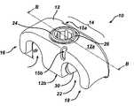
- FIG. 1Ais a side perspective view of one embodiment of a spinal cross connector according to the present invention.
- FIG. 1Bis a cross-sectional view of the spinal cross connector shown in FIG. 1A taken along line B-B;
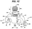
- FIG. 1Cis a disassembled view of the spinal cross connector shown in FIG. 1A ;
- FIG. 1Dis a side view of the spinal cross connector shown in FIG. 1A having first and second spinal fixation rods disposed and engaged therein;
- FIG. 2is a transparent side perspective view of yet another embodiment of a spinal cross connector in a disassembled state
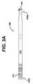
- FIG. 3Ais a perspective view of one embodiment of an insertion tool for use with the spinal cross connector shown in FIG. 1A ;
- FIG. 3Bis an enlarged view of the distal portion of the insertion tool shown in FIG. 3A ;
- FIG. 4Ais a side, partially cross-sectional view of another embodiment of a spinal cross connector in accordance with the present invention.
- FIG. 4Bis an enlarged perspective view of one of the rod-engaging members of the cross connector shown in FIG. 4A ;
- FIG. 5is a side, partially cross-sectional view of yet another embodiment of a spinal cross connector in accordance with the present invention.
- an exemplary cross connectorfor connecting one or more spinal fixation elements, and more preferably for connecting two spinal fixation rods, that are implanted within a patient's spinal system.
- an exemplary cross connector in accordance with the present inventionincludes an elongate body with at least one rod-receiving recess formed therein, and a locking mechanism that is adapted to couple to the elongate body and that is effective to lock a spinal fixation rod within the rod-receiving recess(es).
- cross connector 10is described herein as being adapted to engage a spinal fixation element, and in particular a spinal fixation rod, that a cross connector of the present invention can be configured to engage a variety of spinal fixation elements, such as anchors, cables, fixation plates, etc.
- the cross connectorcan include only one rod-receiving recess for engaging a spinal fixation element, and the opposed terminal end of the cross connector can be adapted for other uses.
- the opposed terminal end of the cross connectorcan be configured to be fixedly attached to a vertebra or vertebral body replacement device or graft.
- the cross connectors of the present inventioncan also include any combination of features described and/or illustrated herein or known in the art, and the cross connector is not limited to the illustrated embodiments.
- FIGS. 1A-1Dillustrate one exemplary embodiment of a cross connector 10 in accordance with the present invention.
- the cross connector 10has a generally elongate body 12 .
- the configuration, shape, and size of the elongate body 12can vary depending on the intended use, but preferably the elongate body 12 has a shape, size, and configuration that allows it to connect to and span two spinal fixation elements, such as spinal rods, that are implanted within a patient's spinal column.
- the elongate body 12includes a central portion 14 with opposed first and second terminal ends 16 , 18 .
- the length L b of the elongate body 12 extending between the opposed terminal ends 14 , 16will vary depending on the intended use.
- the elongate body 12can have a length L b that is in the range of about 10 mm to 30 mm for use in an anterior surgical approach.
- the cross connector 10is provided as part of a kit that includes multiple cross connectors having varying lengths L b .
- the length L b of each cross connector 10 in the kitpreferably differs in increments of about 1 mm.
- the cross connector 10is preferably adapted to connect to and span two spinal fixation elements, such as spinal rods, implanted within a patient's spinal column.
- the cross connector 10can include one or more rod-receiving recesses formed therein.
- FIGS. 1A-1Dillustrate first and second rod-receiving recesses 20 , 22 formed therein and adapted to seat a spinal fixation rod.
- the location of the recesses 20 , 22can vary, but preferably the first and second rod-receiving recesses 20 , 22 are formed substantially adjacent to the first and second terminals ends 16 , 18 of the elongate body 12 .
- the rod-receiving recesses 20 , 22are also preferably formed in a bottom surface 12 b of the elongate body 12 such that they are on an opposite side of the body 12 from a central opening 24 that is formed in the top surface 12 a of the body 12 and which will be discussed in more detail below.
- each recess 20 , 22can vary in shape and size depending on the type of spinal fixation element being engaged.
- the cross connector 10is preferably adapted to connect to two spinal fixation rods.
- each recess 20 , 22can have a shape that is configured to accommodate a substantially cylindrical spinal rod.
- each recess 20 , 22can be substantially concave such that it defines a partially cylindrical cavity.
- the size of the recesses 20 , 22can also vary depending on the size of the spinal fixation element.
- each recess 20 , 22has a depth d r that is greater than a radius of the spinal fixation rod disposed therein.
- the depth d rcan also be greater than a diameter of the spinal fixation rod, or is can be less than or substantially equal to a diameter of the spinal fixation rod.
- the recesses 20 , 22do, however, preferably seat a substantial portion of the spinal fixation rod to allow the rod to be firmly locked therein, as will be discussed in more detail below.
- the cross connector 10can also include one or more rod-engaging members, hereinafter referred to as shoes, that are configured to engage a spinal fixation element disposed within the recesses 20 , 22 .
- the cross connector 10includes first and second shoes 28 , 30 that are slidably disposed within the elongate body 12 adjacent to the first and second rod-receiving recesses 20 , 22 .
- the shoes 28 , 30can have a variety of configurations and they can be mated to or disposed within the elongate body 12 using a variety of techniques, but they are preferably effective to move linearly in response to a force applied thereto by the locking mechanism 26 to lock a spinal fixation rod within each rod-receiving recess 20 , 22 .
- the elongate body 12includes first and second receiving cavities 32 , 34 formed therein for slidably seating the shoes 28 , 30 .
- the first and second cavities 32 , 34preferably extend between the central opening 24 formed in the central portion 14 of the elongate body 12 , and the first and second rod-receiving recesses 20 , 22 in the body 12 .
- the cavities 32 , 34are also preferably spaced a distance apart from the bottom surface 12 b of the elongate body 12 to allow the shoes 28 , 30 to be retained within the body 12 .
- each cavity 32 , 34can vary in shape and size, but they should allow slidable movement of the shoes 20 , 22 therein. More preferably, each cavity 32 , 34 has a shape that is substantially similar to a shape of the shoes 20 , 22 . In the illustrated embodiment, each cavity 32 , 34 has a substantially elongate rectangular shape that is configured to match the contour of each shoe 28 , 30 , as will be discussed below.
- the cavities 32 , 34can also extend at a downward angle from the central bore 24 toward the rod-receiving recesses 20 , 22 such that each shoe 28 , 30 , when moved from within the cavity 32 , 34 toward the rod-receiving recess 20 , 22 , extends in a downward direction. Such a configuration facilitates engagement of the rods disposed within the rod-receiving recesses 20 , 22 .
- each shoe 28 , 30can have a generally rectangular or square cross-sectional shape taken along a plane that extends between an internal surface 28 a , 30 a and an external surface 28 b , 30 b thereof.
- the internal surface 28 a , 30 afaces the central opening 24 when the shoe 28 , 30 is disposed within the cavity 32 , 34 , and the opposed external surface 28 b , 30 b faces the rod-receiving recess 20 , 22 .
- the cross-section of the shoes 28 , 30can be substantially square or rectangular, the internal and external surfaces 28 a , 30 a , 38 b , 30 b can vary in shape.
- the internal surface 28 a , 30 a of each shoe 28 , 30can have a shape that conforms to the shape of the locking mechanism 26 , which will be discussed in more detail below.
- the internal surface 28 a , 30 a of each shoe 28 , 30includes a concave recess formed therein, as shown. The concave shape of the internal surface 28 a , 30 a is effective to seat a portion of the locking mechanism 26 . As is further shown in FIG.
- the external surface 28 b , 30 b of each shoe 28 , 30can have a substantially planar configuration, but each surface 28 b , 30 b can extend at an angle such that a width w 1 at a top portion of each shoe 28 , 30 is less than a width w 2 at a bottom portion of each shoe 28 , 30 .
- the width of each shoe 28 , 30decreases from the top to the bottom. This configuration allows only a mid-portion or the bottom portion of each shoe 28 , 30 to come into contact with a spinal fixation rod disposed within the rod-receiving recess 20 , 22 in the elongate body 12 when the shoes 28 , 30 are in a locked configuration as a result of the locking mechanism 26 .
- each shoe 28 , 30can also be optimizing to facilitate engagement of a spinal fixation rod.
- the surfaces 28 b , 30 b , or at least a portion thereofcan include gripping features, such as ridges, grooves, a surface coating, etc., formed or disposed thereon to engage the rod.
- the first and second shoes 28 , 30are preferably slidably movable between a first retracted position (not shown) in which the shoes 28 , 30 are at least partially or fully disposed within the first and second cavities 32 , 34 in the elongate body 12 , and a second extended position, as shown in FIGS. 1A and 1B , in which at least a portion of the shoes 28 , 30 extend into the recesses 20 , 22 formed within the elongate body 12 . In the first retracted position, at least a portion of the shoes 28 , 30 can extend into the central opening 24 in the elongate body 12 .
- the shoes 28 , 30can be moved into the second extended position by inserting the locking mechanism 26 into the opening 24 such that the locking mechanism 26 applies a force to the first and second movable shoes 28 , 30 to cause the shoes 28 , 30 to move linearly and lock first and second spinal fixation rods within the first and second rod-receiving recesses 20 , 22 .
- the device 10can include a mechanism to slidably retain each shoe 28 , 30 within each cavity 32 , 34 .
- the cross connector 10includes first and second pin members 40 , 42 that extend through the bottom surface 12 b of the body 12 and into a groove 44 , 46 formed within a bottom surface of each shoe 28 , 30 .
- the groove 44 , 46preferably extends between the internal and external faces 28 a , 30 a , 38 b , 30 b of the shoes 28 , 30 to allow the shoes 28 , 30 to slide between the retracted and extended positions.
- the pin members 40 , 42can be retained within the elongate body 12 using various techniques, but preferably the pin members 40 , 42 are fixedly mated to the elongate body 12 using a press fit or using other techniques known in the art.
- FIG. 4Aillustrates a connector 200 that is similar to connector 10 and that includes connector body 212 with shoes 228 and 230 disposed therein.
- each shoe 228 , 230includes a tab that extends toward the central opening 224 of the connector body 212 , and that includes a protrusion formed thereon that is adapted to extend into a bore or groove formed in the connector body 212 .
- the tabs on the shoes 228 , 230are preferably formed on opposite sides of the connector body 212 , thus FIG. 4A only illustrates tab 229 formed on shoe 228 .
- the protrusion 229 a on tab 229is shown in detail in FIG.
- the protrusion 229 a on the tab 229extends into a bore 213 formed in a sidewall of the connector body 212 .
- the tab 229is preferably deflectable to allow the shoe 228 to be snapped into the connector body 212 .
- the protrusion 229 a on the tab 229is free to move within the bore 213 , thus allowing the shoe 228 to slidably move relative to the connector body 212 .
- each shoe 328 , 330is retained within the body 312 of the connector 300 by a hook-type engagement.
- each shoe 328 , 330preferably includes a hook member that extends toward the central opening 324 in the body 312 .
- the hook members on the shoes 328 , 330are preferably formed on opposite sides of the connector body 312 , thus FIG. 5 only illustrates hook member 329 formed on shoe 328 .
- the hook member 329is configured to engage a pin 313 that protrudes into the central opening 324 formed in the connector body 312 such that the hook member 329 extends around the pin 313 .
- the length of the hook member 329allows the shoe 328 to slidably move relative to the connector body 312 while the pin 313 prevents the hook member 329 , and thus the shoe 328 , from falling out of the connector body 312 .
- a person skilled in the artwill appreciate that a variety of other techniques can be used to retain the shoes within the connector body.
- the device 10further includes a locking mechanism 26 that is adapted to apply a force to the shoes 28 , 30 to linearly move the shoes 28 , 30 from the first retracted position to the second extended position.
- the locking mechanism 26can have a variety of configurations and it can be receivable within the elongate body 12 at a variety of locations.
- the elongate body 12includes a central opening 24 formed in a top surface 12 a thereof for receiving the locking mechanism 26 .
- the central opening 24can extend completely through the elongate body 12 , but it preferably terminates at a location that is a distance apart from the bottom surface 12 b of the body 12 .
- the locking mechanism 26which is receivable within the opening 24 , can include a proximal portion 26 a that is adapted to mate to a proximal portion of the central opening 24 , and a distal portion 26 b that is adapted to apply a force to the shoes 28 , 30 to move the shoes 28 , 30 into the second extended position. While various techniques can be used to mate the locking mechanism 26 to the central opening 24 , in the illustrated embodiment the proximal portion 26 a of the locking mechanism 26 includes threads 26 d formed thereon for mating with corresponding threads 25 formed within at least a proximal portion of the central opening 24 .
- the distal portion 26 b of the locking mechanism 26can also vary in shape and size, but in one exemplary embodiment the distal portion 26 b of the locking mechanism 26 is in the form of a shaft or pin-type member. At least a portion of the shaft 26 b preferably tapers toward the distal end to facilitate the application of force against the shoes 28 , 30 .
- the internal surface 28 a , 30 a of each shoe 28 , 30can have a concave recess formed therein for seating the tapered shaft 26 b .
- the tapered shaft 26 bcontacts the concave internal surface 28 a , 30 a of each shoe 28 , 30 to force the shoes 28 , 30 into the second extended position.
- the shaft 26 bcan also have a variety of other shapes such as, for example, a spherical shape or cone shape.
- a person skilled in the artwill appreciate that the shape of the distal portion 26 b of the locking mechanism 26 can vary depending on the shape of the shoes 28 , 30 .
- the cross connector 10can be coupled to one or more, and preferably two, spinal fixation elements, such as spinal rods, that are implanted within a patient's spine, as shown in FIG. 1D .
- spinal fixation elementssuch as spinal rods
- FIG. 1DThis can be achieved by positioning the cross connector 10 such that a spinal rod 70 , 80 is seated within each rod-receiving recess 20 , 22 .
- the shoes 28 , 30are in the first retracted position, as the locking mechanism 26 is not yet inserted into the central opening 24 , or it is only loosely threaded in the central opening 24 .
- the spinal rods 70 , 80may also force the shoes 28 , 30 into the retracted position.
- the locking mechanism 26can then be threaded into the central opening 24 .
- the distal shaft 26 bwill contact the internal surface 28 a , 30 a of the shoes 28 , 30 to push the shoes 28 , 30 toward the rod-receiving recesses 20 , 22 , thereby pushing the shoes 28 , 30 against the spinal rods 70 , 80 disposed therein.
- the locking mechanism 26is threaded until the shoes 28 , 30 lock the rods 70 , 80 into the recesses 20 , 22 , as shown in FIG. 1D .
- the threads 26 d on the locking mechanism 26 and the threads 25 in the central opening 24can optionally be designed such that, when the locking mechanism 26 is fully threaded into the central opening 24 , the shoes 28 , 30 are in a locked position.
- the threads 26 d , 25can also be designed to allow some minor movement between the locking mechanism 26 and the elongate body 12 to allow for any imbalance between the position of the shoes 28 , 30 . Imbalances can occur as a result of the position of the spinal rods implanted in the patient's spine, e.g., when the rods are not parallel to one another.
- a minor gapcan be provided between the threads 25 in the central opening such that the locking mechanism 26 can slightly move side-to-side when disposed therein.
- a person skilled in the artwill appreciate that a variety of other techniques can be used to facilitate the equal distribution of force by the locking mechanism 26 onto the shoes 28 , 30 such that the shoes 28 , 30 .
- the locking mechanism 26can have a variety of other configurations, and a variety of other techniques can be used to move the shoes 28 , 30 between the first retracted position and the second extended position, and to lock the shoes in a fixed position to engage spinal fixation elements disposed within the recesses 20 , 22 .
- FIG. 2illustrates another embodiment of a locking mechanism 26 ′ that includes two separate components: a ball-type member 26 b ′ and a threaded member 26 a ′.
- the ball-type member 26 b ′sits within the central opening 24 ′ in the elongate body 12 ′, and the threaded member 26 a ′ can be threaded into the opening 24 ′ to push the ball-type member 26 b ′ downward, thereby moving the shoes 28 ′, 30 ′ into the extended position.
- the present inventionalso provides an inserter tool 100 that can be used to position a spinal implant or device with respect to one or more spinal fixation elements, such as two spinal rods. While the tool 100 is described for use with cross connector 10 , the tool can be used with a variety of spinal implants and devices. Referring to FIGS. 3A-3B , one exemplary embodiment of an inserter tool 100 is shown in accordance with the present invention.
- the tool 100includes an elongate shaft 102 having a proximal handle end 102 a and a distal end 102 b .
- the elongate shaft 102is preferably hollow to allow other tools, such as a driver for rotating the locking mechanism 26 , to be inserted therethrough.
- the proximal handle end 102 acan have a variety of configurations, shapes, and sizes, but it is preferably adapted to allow a user to easily grasp the tool 100 .
- the handle 102 aincludes ridges 103 formed thereon to facilitate grasping of the device 100 .
- the distal end 102 b of the elongate shaft 102is configured to grasp the cross connector 10 to position the cross connector 10 in relation to one or more spinal fixation elements implanted in a patient's spine.
- the distal end 102 b of the elongate shaft 102 of the inserter tool 100is shown in more detail in FIG. 3B , and as shown the distal end 102 b includes first and second arms 106 , 108 which are effective to engage the central portion 14 of the cross connector 10 .
- the arms 106 , 108preferably define a cavity 104 therebetween that has a shape that generally corresponds to the contour of the central portion 14 of the cross connector 10 .
- the cavity 104can be substantially square or rectangular in shape to receive the central portion 14 .
- the distal end 102 b of the inserter tool 100can also have a substantially square or rectangular shape to define the shape of the cavity 104 as well as the position of the arms 106 , 108 relative to one another.
- Each arm 106 , 108 of the inserter tool 100can also be flexible, or include a flexible portion, to create a friction fit between the arms 106 , 108 and the central portion 14 of the cross connector, thereby allowing the cross connector 10 to be removably mated to the inserter tool 100 .
- arm 106has a flexible tab 106 a formed at a substantial mid-portion thereof.
- arm 108can also include a flexible tab 108 a formed thereon.
- the flexible tabs 106 a , 108 acan have any shape and size, but they preferably define a distance d a ( FIG. 3A ) therebetween that is equal to or slightly less than a width w c ( FIG. 1C ) of the central portion 14 of the cross connector 10 .
- the arms 106 , 108 of the inserter tool 100can also include one or more features formed thereon for aligning the tool 100 with the cross connector 10 .
- an inner surface of each arm 106 , 108can include a protrusion (not shown) formed thereon for fitting within a corresponding detent or groove formed on the central portion 14 of the cross connector.
- the protrusionsare formed on diagonally opposed ends of the opposed arms 106 , 108 , and the grooves 15 a , 15 b are formed on diagonally opposed sides of the central portion 14 of the cross connector 10 , as shown in FIG. 1A . This allows the inserter tool 100 to be properly aligned with the cross connector 10 , and in particular such a feature is effective to align the lumen extending through the inserter tool 100 with the central opening 24 formed in the cross connector 10 .
- the inserter tool 100can also optionally include one or more cut-out portions or windows formed therein to facilitate viewing of the central opening 24 in the cross connector 10 when the cross connector 10 is coupled to the tool 100 .
- FIG. 3Billustrates window 110 formed in the shaft 102 of the inserter tool 100 just proximal to the distal end 102 b . While not shown, a second window can be formed opposed to the first window 110 .
- the present inventionalso provides a method for coupling to spinal fixation elements, such as spinal rods, implanted within a patient's spinal column.
- spinal fixation elementssuch as spinal rods
- the rods 70 , 80can be rigidly coupled to one another by positioning the cross connector 10 over the rods 70 , 80 such that the rods 70 , 80 sit within the recesses 20 , 22 in the cross connector 10 .
- the inserter tool 100can be used to facilitate such positioning of the cross connector 10 .
- the cross connector 10can be positioned between and engaged by the opposed arms 106 , 108 of the inserter tool 100 .
- the tool 100can then be manipulated to position the cross connector 10 over the rods 70 , 80 .
- a driver mechanism(not shown) can then be inserted through the hollow elongate shaft 102 of the inserter tool 100 to rotate the locking mechanism 26 , which is preferably loosely pre-threaded into the central opening 24 , thereby moving the shoes 28 , 30 to lock the spinal rods 70 , 80 relative to the cross connector 10 .
Landscapes
- Health & Medical Sciences (AREA)
- Orthopedic Medicine & Surgery (AREA)
- Neurology (AREA)
- Life Sciences & Earth Sciences (AREA)
- Surgery (AREA)
- Heart & Thoracic Surgery (AREA)
- Engineering & Computer Science (AREA)
- Biomedical Technology (AREA)
- Nuclear Medicine, Radiotherapy & Molecular Imaging (AREA)
- Medical Informatics (AREA)
- Molecular Biology (AREA)
- Animal Behavior & Ethology (AREA)
- General Health & Medical Sciences (AREA)
- Public Health (AREA)
- Veterinary Medicine (AREA)
- Surgical Instruments (AREA)
- Prostheses (AREA)
Abstract
Description
Claims (22)
Priority Applications (9)
| Application Number | Priority Date | Filing Date | Title |
|---|---|---|---|
| US10/929,095US7717938B2 (en) | 2004-08-27 | 2004-08-27 | Dual rod cross connectors and inserter tools |
| AU2005280613AAU2005280613B2 (en) | 2004-08-27 | 2005-06-22 | Dual rod cross connectors and inserter tools |
| JP2007529839AJP4902539B2 (en) | 2004-08-27 | 2005-06-22 | Dual rod cross connector and insertion tool |
| PCT/US2005/021794WO2006025919A2 (en) | 2004-08-27 | 2005-06-22 | Dual rod cross connectors and inserter tools |
| CA2578947ACA2578947C (en) | 2004-08-27 | 2005-06-22 | Dual rod cross connectors and inserter tools |
| AT05764484TATE538739T1 (en) | 2004-08-27 | 2005-06-22 | DOUBLE ROD CROSS CONNECTORS AND INSERTION TOOLS |
| EP05764484AEP1781194B1 (en) | 2004-08-27 | 2005-06-22 | Dual rod cross connectors and inserter tools |
| US12/248,389US8372119B2 (en) | 2004-08-27 | 2008-10-09 | Dual rod cross connectors and inserter tools |
| US13/736,620US8961572B2 (en) | 2004-08-27 | 2013-01-08 | Dual rod cross connectors and inserter tools |
Applications Claiming Priority (1)
| Application Number | Priority Date | Filing Date | Title |
|---|---|---|---|
| US10/929,095US7717938B2 (en) | 2004-08-27 | 2004-08-27 | Dual rod cross connectors and inserter tools |
Related Child Applications (1)
| Application Number | Title | Priority Date | Filing Date |
|---|---|---|---|
| US12/248,389ContinuationUS8372119B2 (en) | 2004-08-27 | 2008-10-09 | Dual rod cross connectors and inserter tools |
Publications (2)
| Publication Number | Publication Date |
|---|---|
| US20060058789A1 US20060058789A1 (en) | 2006-03-16 |
| US7717938B2true US7717938B2 (en) | 2010-05-18 |
Family
ID=36000473
Family Applications (3)
| Application Number | Title | Priority Date | Filing Date |
|---|---|---|---|
| US10/929,095Expired - LifetimeUS7717938B2 (en) | 2004-08-27 | 2004-08-27 | Dual rod cross connectors and inserter tools |
| US12/248,389Active2027-04-20US8372119B2 (en) | 2004-08-27 | 2008-10-09 | Dual rod cross connectors and inserter tools |
| US13/736,620Expired - LifetimeUS8961572B2 (en) | 2004-08-27 | 2013-01-08 | Dual rod cross connectors and inserter tools |
Family Applications After (2)
| Application Number | Title | Priority Date | Filing Date |
|---|---|---|---|
| US12/248,389Active2027-04-20US8372119B2 (en) | 2004-08-27 | 2008-10-09 | Dual rod cross connectors and inserter tools |
| US13/736,620Expired - LifetimeUS8961572B2 (en) | 2004-08-27 | 2013-01-08 | Dual rod cross connectors and inserter tools |
Country Status (7)
| Country | Link |
|---|---|
| US (3) | US7717938B2 (en) |
| EP (1) | EP1781194B1 (en) |
| JP (1) | JP4902539B2 (en) |
| AT (1) | ATE538739T1 (en) |
| AU (1) | AU2005280613B2 (en) |
| CA (1) | CA2578947C (en) |
| WO (1) | WO2006025919A2 (en) |
Cited By (40)
| Publication number | Priority date | Publication date | Assignee | Title |
|---|---|---|---|---|
| US20080312697A1 (en)* | 2007-06-15 | 2008-12-18 | Robert Reid, Inc. | System and Method for Polyaxially Adjustable Bone Anchorage |
| US20090030462A1 (en)* | 2007-07-26 | 2009-01-29 | Glenn R. Buttermann, M.D. | Segmental Orthopaedic device for spinal elongation and for treatment of Scoliosis |
| US20090136290A1 (en)* | 2007-11-23 | 2009-05-28 | Zirkona Sweden Ab | Ball joint device |
| US20110137353A1 (en)* | 2007-07-26 | 2011-06-09 | Buttermann Glenn R | Segmental orthopedic device for spinal elongation and for treatment of scoliosis |
| US20110188925A1 (en)* | 2008-09-05 | 2011-08-04 | Big Alpha Co., Inc. | Joint unit |
| US8246657B1 (en) | 2009-06-29 | 2012-08-21 | Nuvasive, Inc. | Spinal cross connector |
| US20130268003A1 (en)* | 2012-04-05 | 2013-10-10 | Tufts Medical Center, Inc. | Spring loaded mechanism for managing scoliosis |
| US8556937B2 (en) | 2004-03-31 | 2013-10-15 | DePuy Synthes Products, LLC | Rod attachment for head to head cross connector |
| US20130274801A1 (en)* | 2012-04-16 | 2013-10-17 | Aesculap Implant Systems, Llc | Rod to rod cross connector |
| US8771319B2 (en) | 2012-04-16 | 2014-07-08 | Aesculap Implant Systems, Llc | Rod to rod cross connector |
| US8870921B2 (en) | 2006-11-08 | 2014-10-28 | DePuy Synthes Products, LLC | Spinal cross connectors |
| US8920471B2 (en) | 2010-07-12 | 2014-12-30 | K2M, Inc. | Transverse connector |
| US8954165B2 (en) | 2012-01-25 | 2015-02-10 | Nevro Corporation | Lead anchors and associated systems and methods |
| US8961572B2 (en) | 2004-08-27 | 2015-02-24 | Depuy Synthes Products Llc | Dual rod cross connectors and inserter tools |
| US8992579B1 (en) | 2011-03-08 | 2015-03-31 | Nuvasive, Inc. | Lateral fixation constructs and related methods |
| US9060815B1 (en) | 2012-03-08 | 2015-06-23 | Nuvasive, Inc. | Systems and methods for performing spine surgery |
| US9265935B2 (en) | 2013-06-28 | 2016-02-23 | Nevro Corporation | Neurological stimulation lead anchors and associated systems and methods |
| US9277950B2 (en) | 2010-06-10 | 2016-03-08 | Dynamic Spine, Llc | Low-profile, uniplanar bone screw |
| US9381044B2 (en) | 2010-01-26 | 2016-07-05 | Pioneer Surgical Technology, Inc. | Posterior spinal stabilization plate device |
| US9517089B1 (en) | 2013-10-08 | 2016-12-13 | Nuvasive, Inc. | Bone anchor with offset rod connector |
| US9579126B2 (en) | 2008-02-02 | 2017-02-28 | Globus Medical, Inc. | Spinal rod link reducer |
| US20170333088A1 (en)* | 2016-05-18 | 2017-11-23 | Medos International Sarl | Implant connectors and related methods |
| US20180064469A1 (en)* | 2015-04-24 | 2018-03-08 | K2M, Inc. | Tethering screw system |
| US9936982B2 (en) | 2012-11-26 | 2018-04-10 | Spinefrontier, Inc | System and method for translateral linking of bilateral spinal fixation rods |
| US9980755B2 (en) | 2016-03-29 | 2018-05-29 | Globus Medical, Inc. | Revision connectors, systems, and methods thereof |
| WO2019028042A1 (en) | 2017-07-31 | 2019-02-07 | Medos International Sàrl | Connectors for use in systems and methods for reducing the risk of proximal junctional kyphosis |
| US10238432B2 (en) | 2017-02-10 | 2019-03-26 | Medos International Sàrl | Tandem rod connectors and related methods |
| US10307185B2 (en) | 2016-03-29 | 2019-06-04 | Globus Medical, Inc. | Revision connectors, systems, and methods thereof |
| US10383663B2 (en) | 2016-03-29 | 2019-08-20 | Globus Medical, Inc. | Revision connectors, systems and methods thereof |
| US10398476B2 (en) | 2016-12-13 | 2019-09-03 | Medos International Sàrl | Implant adapters and related methods |
| US10463403B2 (en) | 2017-07-31 | 2019-11-05 | Medos International Sarl | Systems and methods for reducing the risk of proximal junctional kyphosis using a bone anchor or other attachment point |
| US10492835B2 (en) | 2016-12-19 | 2019-12-03 | Medos International Sàrl | Offset rods, offset rod connectors, and related methods |
| US10517647B2 (en) | 2016-05-18 | 2019-12-31 | Medos International Sarl | Implant connectors and related methods |
| US10561454B2 (en) | 2017-03-28 | 2020-02-18 | Medos International Sarl | Articulating implant connectors and related methods |
| US10624679B2 (en) | 2016-03-29 | 2020-04-21 | Globus Medical, Inc. | Revision connectors, systems and methods thereof |
| US10966761B2 (en) | 2017-03-28 | 2021-04-06 | Medos International Sarl | Articulating implant connectors and related methods |
| US11076890B2 (en) | 2017-12-01 | 2021-08-03 | Medos International Sàrl | Rod-to-rod connectors having robust rod closure mechanisms and related methods |
| US11284924B1 (en) | 2020-12-16 | 2022-03-29 | Warsaw Orthopedic, Inc | Adjustable spinal implant, system and method |
| US11350969B1 (en) | 2021-02-02 | 2022-06-07 | Warsaw Orthopedic, Inc. | Rotatable spinal implant, system, and method |
| US11504165B1 (en)* | 2018-10-22 | 2022-11-22 | Advance Research System, Llc | Asymmetric clamp with ultrasonic tissue removal capability |
Families Citing this family (49)
| Publication number | Priority date | Publication date | Assignee | Title |
|---|---|---|---|---|
| US8480712B1 (en) | 2004-01-06 | 2013-07-09 | Nuvasive, Inc. | System and method for performing spinal fixation |
| US7645294B2 (en) | 2004-03-31 | 2010-01-12 | Depuy Spine, Inc. | Head-to-head connector spinal fixation system |
| US20070225713A1 (en)* | 2004-10-20 | 2007-09-27 | Moti Altarac | Systems and methods for posterior dynamic stabilization of the spine |
| US20060233597A1 (en)* | 2005-04-18 | 2006-10-19 | Ensign Micheal D | Cam based rod connection system and method |
| US7628799B2 (en)* | 2005-08-23 | 2009-12-08 | Aesculap Ag & Co. Kg | Rod to rod connector |
| EP1931269A1 (en)* | 2005-10-07 | 2008-06-18 | Alphatec Spine, Inc. | Transverse rod connector |
| US7942901B2 (en)* | 2006-04-24 | 2011-05-17 | Warsaw Orthopedic, Inc. | Connector apparatus |
| AU2011203292B2 (en)* | 2006-11-08 | 2014-05-22 | Depuy Spine, Inc. | Spinal cross connectors |
| US7744632B2 (en)* | 2006-12-20 | 2010-06-29 | Aesculap Implant Systems, Inc. | Rod to rod connector |
| US9993619B2 (en) | 2007-07-17 | 2018-06-12 | C. R. Bard, Inc. | Securement system for a medical article |
| US8348976B2 (en)* | 2007-08-27 | 2013-01-08 | Kyphon Sarl | Spinous-process implants and methods of using the same |
| KR101567593B1 (en)* | 2007-09-25 | 2015-11-09 | 신세스 게엠바하 | transconnector |
| US9474554B2 (en)* | 2007-10-23 | 2016-10-25 | Lee A. Strnad | Spinal rod cross connector |
| US20090105756A1 (en) | 2007-10-23 | 2009-04-23 | Marc Richelsoph | Spinal implant |
| US9060813B1 (en) | 2008-02-29 | 2015-06-23 | Nuvasive, Inc. | Surgical fixation system and related methods |
| US9603629B2 (en) | 2008-09-09 | 2017-03-28 | Intelligent Implant Systems Llc | Polyaxial screw assembly |
| US8951289B2 (en)* | 2008-10-09 | 2015-02-10 | Total Connect Spine, Llc | Spinal connection assembly |
| EP2421454A4 (en)* | 2009-04-23 | 2013-12-11 | Spinal Elements Inc | Transverse connectors |
| US8372120B2 (en) | 2009-05-20 | 2013-02-12 | Spine Wave, Inc. | Multi-axial cross connector |
| CA2776239C (en) | 2009-10-06 | 2018-06-05 | Venetec International, Inc. | Stabilizing device having a snap clamp |
| US9198696B1 (en) | 2010-05-27 | 2015-12-01 | Nuvasive, Inc. | Cross-connector and related methods |
| US9387013B1 (en) | 2011-03-01 | 2016-07-12 | Nuvasive, Inc. | Posterior cervical fixation system |
| US9247964B1 (en) | 2011-03-01 | 2016-02-02 | Nuasive, Inc. | Spinal Cross-connector |
| CA2831081A1 (en) | 2011-04-07 | 2012-10-11 | Mike Hammer | Clamp for spinal cross connecting device |
| WO2012145683A1 (en)* | 2011-04-21 | 2012-10-26 | Venetec International, Inc. | Anchoring system |
| JP6106662B2 (en)* | 2011-05-17 | 2017-04-05 | ジンマー,インコーポレイティド | External fixed clamping system using a starting mechanism and stored spring energy |
| WO2013073975A2 (en)* | 2011-11-18 | 2013-05-23 | Orthopaedic International, Inc. | Parallel rod connector |
| US8945186B2 (en) | 2011-12-30 | 2015-02-03 | Blackstone Medical, Inc. | Multi-axial spinal cross connecting device |
| US8556942B2 (en) | 2011-12-30 | 2013-10-15 | Blackstone Medical, Inc. | Occipito-cervical fixation assembly and method for constructing same |
| EP2662037B1 (en)* | 2012-05-09 | 2023-01-11 | CoLigne AG | Iliac connector, connector head and spinal fixation system |
| US9011450B2 (en) | 2012-08-08 | 2015-04-21 | DePuy Synthes Products, LLC | Surgical instrument |
| US9464461B2 (en)* | 2012-08-31 | 2016-10-11 | Ron R. Daniels | Lock device and method of use |
| US9339309B1 (en) | 2012-10-11 | 2016-05-17 | Nuvasive, Inc. | Systems and methods for inserting cross-connectors |
| CA2899167C (en)* | 2013-01-25 | 2021-08-31 | DePuy Synthes Products, Inc. | Caps for implants, implant assemblies, and methods of use |
| US9044273B2 (en) | 2013-10-07 | 2015-06-02 | Intelligent Implant Systems, Llc | Polyaxial plate rod system and surgical procedure |
| US9486252B2 (en)* | 2014-01-09 | 2016-11-08 | Warsaw Orthopedic, Inc. | Spinal correction system and method |
| US9724131B2 (en)* | 2014-09-25 | 2017-08-08 | DePuy Synthes Products, Inc. | Spinal connectors and related methods |
| US9763703B2 (en) | 2015-05-05 | 2017-09-19 | Degen Medical, Inc. | Cross connectors, kits, and methods |
| US9795421B2 (en)* | 2015-07-07 | 2017-10-24 | K2M, Inc. | Spinal construct with flexible member |
| ITUB20156292A1 (en)* | 2015-12-03 | 2017-06-03 | Medacta Int Sa | CONNECTION ELEMENT BETWEEN BARS IN A SPINOSY RECONSTRUCTION SYSTEM |
| US20170325849A1 (en)* | 2016-05-13 | 2017-11-16 | Spineology Inc. | Multiple diameter spinal rod clamping mechanism |
| US20180243012A1 (en)* | 2017-02-24 | 2018-08-30 | Warsaw Orthopedic, Inc | Spinal implant system and method |
| US11051857B2 (en) | 2017-08-10 | 2021-07-06 | Ortho Development Corporation | Tether clamping assemblies and related methods and apparatus |
| US11071569B2 (en) | 2017-08-10 | 2021-07-27 | Ortho Development Corporation | Nesting tether clamping assemblies and related methods and apparatus |
| US10859339B2 (en)* | 2018-11-13 | 2020-12-08 | Qtm, Llc | Archery riser and method |
| US11819255B2 (en) | 2019-10-07 | 2023-11-21 | Ortho Development Corporation | Tether tensioning instrumentation and related methods |
| EP4106650A1 (en)* | 2020-02-21 | 2022-12-28 | Inno4Spine AG | Connector implant for connecting two posterior rod portions |
| EP3943028B1 (en)* | 2020-07-22 | 2023-10-04 | Biedermann Technologies GmbH & Co. KG | Rod system including at least two rods and connector device for rods |
| US11331125B1 (en) | 2021-10-07 | 2022-05-17 | Ortho Inventions, Llc | Low profile rod-to-rod coupler |
Citations (256)
| Publication number | Priority date | Publication date | Assignee | Title |
|---|---|---|---|---|
| US180881A (en) | 1876-08-08 | Improvement in ball-and-socket supports | ||
| US457964A (en) | 1891-08-18 | Frank h | ||
| US483342A (en) | 1892-09-27 | bolte | ||
| US596729A (en) | 1898-01-04 | Support for electric lamps | ||
| US900717A (en) | 1907-09-26 | 1908-10-13 | Edward B Feaster | Cable fastener or clamp. |
| GB167228A (en) | 1920-04-26 | 1921-07-26 | Stanley Watkin Darker | Improvements in or relating to nut locks |
| US1455441A (en) | 1920-05-03 | 1923-05-15 | Hodny William La | Bracket for supporting mirrors and the like |
| DE867422C (en) | 1951-11-13 | 1953-02-16 | Alfred Dr Med Abel | Screw-on bone plate for the healing of broken bones |
| US2638301A (en) | 1947-01-28 | 1953-05-12 | Donald M Smith | Attachment structure for laboratory clamps |
| US3012091A (en)* | 1959-10-20 | 1961-12-05 | Schiffmann Alois | Electrical connector |
| US3019504A (en) | 1959-04-29 | 1962-02-06 | Burroughs Corp | Tape and terminal fitting assembly |
| US3499222A (en) | 1965-08-17 | 1970-03-10 | Leonard I Linkow | Intra-osseous pins and posts and their use and techniques thereof |
| US3752203A (en) | 1971-07-28 | 1973-08-14 | Hill Fastener Corp | Lock-screw fasteners |
| US4011602A (en) | 1975-10-06 | 1977-03-15 | Battelle Memorial Institute | Porous expandable device for attachment to bone tissue |
| US4085744A (en) | 1977-01-31 | 1978-04-25 | David Warren Lewis | Spinal column prostheses orthoses |
| US4179905A (en) | 1977-04-07 | 1979-12-25 | Gelenkwellenbau Gmbh | Bearing system in a universal joint |
| US4289124A (en) | 1978-09-18 | 1981-09-15 | Zickel Robert E | Surgical appliance for the fixation of fractured bones |
| US4404967A (en) | 1982-01-18 | 1983-09-20 | Wyzsza Szkola Inzynierska Im. Jurija Gagarina | Surgical strut for treatment of the back-bone |
| US4411259A (en) | 1980-02-04 | 1983-10-25 | Drummond Denis S | Apparatus for engaging a hook assembly to a spinal column |
| US4611580A (en) | 1983-11-23 | 1986-09-16 | Henry Ford Hospital | Intervertebral body stabilization |
| US4611581A (en) | 1983-12-16 | 1986-09-16 | Acromed Corporation | Apparatus for straightening spinal columns |
| US4611582A (en) | 1983-12-27 | 1986-09-16 | Wisconsin Alumni Research Foundation | Vertebral clamp |
| US4641636A (en) | 1983-05-04 | 1987-02-10 | Cotrel Yves P C A | Device for supporting the rachis |
| US4648388A (en) | 1985-11-01 | 1987-03-10 | Acromed Corporation | Apparatus and method for maintaining vertebrae in a desired relationship |
| US4653481A (en) | 1985-07-24 | 1987-03-31 | Howland Robert S | Advanced spine fixation system and method |
| US4655199A (en) | 1985-03-29 | 1987-04-07 | Acromed Corporation | Spinal column straightening apparatus |
| US4658809A (en) | 1983-02-25 | 1987-04-21 | Firma Heinrich C. Ulrich | Implantable spinal distraction splint |
| US4696290A (en) | 1983-12-16 | 1987-09-29 | Acromed Corporation | Apparatus for straightening spinal columns |
| GB2173104B (en) | 1984-02-28 | 1987-11-25 | Peter John Webb | Spinal fixation apparatus |
| US4719905A (en) | 1985-11-01 | 1988-01-19 | Acromed Corporation | Apparatus and method for maintaining vertebrae in a desired relationship |
| DE3219575C2 (en) | 1982-05-25 | 1988-02-18 | Patrick Dr.Med. 3590 Bad Wildungen De Kluger | |
| US4743260A (en) | 1985-06-10 | 1988-05-10 | Burton Charles V | Method for a flexible stabilization system for a vertebral column |
| US4759769A (en) | 1987-02-12 | 1988-07-26 | Health & Research Services Inc. | Artificial spinal disc |
| US4771767A (en) | 1986-02-03 | 1988-09-20 | Acromed Corporation | Apparatus and method for maintaining vertebrae in a desired relationship |
| US4773402A (en) | 1985-09-13 | 1988-09-27 | Isola Implants, Inc. | Dorsal transacral surgical implant |
| US4805602A (en) | 1986-11-03 | 1989-02-21 | Danninger Medical Technology | Transpedicular screw and rod system |
| FR2615095B1 (en) | 1987-05-15 | 1989-08-18 | Fabrication Materiel Orthopedi | OSTEOSYNTHESIS INSTRUMENTATION FOR THE CORRECTION OF LUMBAR SCOLIOSES BY POSTERIOR PATHWAY |
| US4887595A (en) | 1987-07-29 | 1989-12-19 | Acromed Corporation | Surgically implantable device for spinal columns |
| US4913134A (en) | 1987-07-24 | 1990-04-03 | Biotechnology, Inc. | Spinal fixation system |
| US4950269A (en) | 1988-06-13 | 1990-08-21 | Acromed Corporation | Spinal column fixation device |
| US4957495A (en) | 1987-04-01 | 1990-09-18 | Patrick Kluger | Device for setting the spinal column |
| FR2645427A1 (en) | 1989-04-11 | 1990-10-12 | Cotrel Yves | Transverse fixing bar for spinal osteosynthesis device |
| GB2208476B (en) | 1987-08-07 | 1990-10-31 | Seyed Mohammad Hossein Mehdian | Improvements in or relating to apparatus for use in the treatment of spinal disorders |
| US5002542A (en) | 1989-10-30 | 1991-03-26 | Synthes U.S.A. | Pedicle screw clamp |
| US5005562A (en) | 1988-06-24 | 1991-04-09 | Societe De Fabrication De Material Orthopedique | Implant for spinal osteosynthesis device, in particular in traumatology |
| US5010879A (en) | 1989-03-31 | 1991-04-30 | Tanaka Medical Instrument Manufacturing Co. | Device for correcting spinal deformities |
| US5024213A (en) | 1989-02-08 | 1991-06-18 | Acromed Corporation | Connector for a corrective device |
| US5030220A (en) | 1990-03-29 | 1991-07-09 | Advanced Spine Fixation Systems Incorporated | Spine fixation system |
| US5067955A (en) | 1989-04-13 | 1991-11-26 | Societe De Fabrication De Material Orthopedique | Vertebral implant for osteosynthesis device |
| US5084049A (en) | 1989-02-08 | 1992-01-28 | Acromed Corporation | Transverse connector for spinal column corrective devices |
| US5092893A (en) | 1990-09-04 | 1992-03-03 | Smith Thomas E | Human orthopedic vertebra implant |
| US5092866A (en) | 1989-02-03 | 1992-03-03 | Breard Francis H | Flexible inter-vertebral stabilizer as well as process and apparatus for determining or verifying its tension before installation on the spinal column |
| US5102412A (en) | 1990-06-19 | 1992-04-07 | Chaim Rogozinski | System for instrumentation of the spine in the treatment of spinal deformities |
| US5113685A (en) | 1991-01-28 | 1992-05-19 | Acromed Corporation | Apparatus for contouring spine plates and/or rods |
| US5116334A (en) | 1988-12-21 | 1992-05-26 | Zimmer, Inc. | Posterior spinal system and method |
| US5120171A (en) | 1990-11-27 | 1992-06-09 | Stuart Surgical | Bone screw with improved threads |
| US5127912A (en) | 1990-10-05 | 1992-07-07 | R. Charles Ray | Sacral implant system |
| US5129900A (en) | 1990-07-24 | 1992-07-14 | Acromed Corporation | Spinal column retaining method and apparatus |
| US5133716A (en) | 1990-11-07 | 1992-07-28 | Codespi Corporation | Device for correction of spinal deformities |
| US5147359A (en) | 1988-12-21 | 1992-09-15 | Zimmer, Inc. | Spinal hook body |
| US5147360A (en) | 1990-02-19 | 1992-09-15 | Societe De Fabrication De Materiel Orthopedique | Osteosynthesis device for the correction of spinal curvatures |
| US5154718A (en) | 1988-12-21 | 1992-10-13 | Zimmer, Inc. | Spinal coupler assembly |
| EP0242708B1 (en) | 1986-04-25 | 1992-11-19 | Jürgen Prof. Dr. Harms | Pedicle screw |
| US5176680A (en) | 1990-02-08 | 1993-01-05 | Vignaud Jean Louis | Device for the adjustable fixing of spinal osteosynthesis rods |
| US5176678A (en) | 1991-03-14 | 1993-01-05 | Tsou Paul M | Orthopaedic device with angularly adjustable anchor attachments to the vertebrae |
| US5190543A (en) | 1990-11-26 | 1993-03-02 | Synthes (U.S.A.) | Anchoring device |
| US5207678A (en) | 1989-07-20 | 1993-05-04 | Prufer | Pedicle screw and receiver member therefore |
| US5234431A (en) | 1991-04-03 | 1993-08-10 | Waldemar Link Gmbh & Co. | Bone plate arrangement |
| US5242443A (en) | 1991-08-15 | 1993-09-07 | Smith & Nephew Dyonics, Inc. | Percutaneous fixation of vertebrae |
| US5261907A (en) | 1991-05-17 | 1993-11-16 | Vignaud Jean L | Interconnecting device able to lock spinal osteosynthesis fasteners |
| US5261913A (en) | 1989-07-26 | 1993-11-16 | J.B.S. Limited Company | Device for straightening, securing, compressing and elongating the spinal column |
| US5275600A (en) | 1992-10-05 | 1994-01-04 | Zimmer, Inc. | Telescoping rod to rod coupler for a spinal system |
| US5282801A (en) | 1993-02-17 | 1994-02-01 | Danek Medical, Inc. | Top tightening clamp assembly for a spinal fixation system |
| FR2624720B1 (en) | 1987-12-21 | 1994-04-15 | Fabrication Materiel Orthopediqu | IMPLANT FOR OSTEOSYNTHESIS DEVICE, ESPECIALLY OF THE RACHIS |
| US5304177A (en) | 1992-06-26 | 1994-04-19 | Dietmar Pennig | Auxiliary device for osteosynthesis |
| US5306275A (en) | 1992-12-31 | 1994-04-26 | Bryan Donald W | Lumbar spine fixation apparatus and method |
| US5312405A (en) | 1992-07-06 | 1994-05-17 | Zimmer, Inc. | Spinal rod coupler |
| US5330473A (en) | 1993-03-04 | 1994-07-19 | Advanced Spine Fixation Systems, Inc. | Branch connector for spinal fixation systems |
| US5334203A (en) | 1992-09-30 | 1994-08-02 | Amei Technologies Inc. | Spinal fixation system and methods |
| US5360431A (en) | 1990-04-26 | 1994-11-01 | Cross Medical Products | Transpedicular screw system and method of use |
| US5366455A (en) | 1988-11-04 | 1994-11-22 | Surgicraft Limited | Pedicle engaging means |
| US5368594A (en) | 1991-09-30 | 1994-11-29 | Fixano S.A. | Vertebral osteosynthesis device |
| FR2697743B1 (en) | 1992-11-09 | 1995-01-27 | Fabrication Mat Orthopedique S | Spinal osteosynthesis device applicable in particular to degenerative vertebrae. |
| US5387213A (en) | 1991-02-05 | 1995-02-07 | Safir S.A.R.L. | Osseous surgical implant particularly for an intervertebral stabilizer |
| US5395370A (en) | 1991-10-18 | 1995-03-07 | Pina Vertriebs Ag | Vertebral compression clamp for surgical repair to damage to the spine |
| US5397636A (en) | 1991-12-11 | 1995-03-14 | Tonen Corporation | Hybrid laminated prepreg and ski pole shaft using the same |
| US5397363A (en) | 1992-08-11 | 1995-03-14 | Gelbard; Steven D. | Spinal stabilization implant system |
| DE4330837A1 (en) | 1993-09-11 | 1995-03-16 | Michael Hahn | Pedicle screw and internal fixator |
| US5403316A (en) | 1993-12-02 | 1995-04-04 | Danek Medical, Inc. | Triangular construct for spinal fixation |
| US5415661A (en) | 1993-03-24 | 1995-05-16 | University Of Miami | Implantable spinal assist device |
| US5419522A (en) | 1992-05-06 | 1995-05-30 | New Focus, Inc. | Universal optical mount |
| US5423818A (en) | 1993-02-17 | 1995-06-13 | Danek Medical, Inc. | Clamp for attaching a vertebral fixation element to a spinal rod |
| FR2714590A1 (en) | 1994-01-05 | 1995-07-07 | Lenfant Jean Pierre | Transverse fixing member for spinal column supporting rods |
| US5437671A (en) | 1992-03-10 | 1995-08-01 | Zimmer, Inc. | Perpendicular rod connector for spinal fixation device |
| US5439463A (en) | 1993-11-12 | 1995-08-08 | Lin; Chih-I | Spinal clamping device |
| US5454812A (en) | 1993-11-12 | 1995-10-03 | Lin; Chih-I | Spinal clamping device having multiple distance adjusting strands |
| US5470333A (en) | 1993-03-11 | 1995-11-28 | Danek Medical, Inc. | System for stabilizing the cervical and the lumbar region of the spine |
| US5474086A (en) | 1992-07-07 | 1995-12-12 | Chattanooga Group, Inc. | Apparatus for monitoring the motion of the lumbar spine |
| US5476462A (en) | 1992-06-30 | 1995-12-19 | Zimmer, Inc. | Spinal implant system |
| US5487742A (en) | 1990-03-08 | 1996-01-30 | Sofamore Danek Group | Transverse fixation device for a spinal osteosynthesis system |
| US5496321A (en) | 1993-11-19 | 1996-03-05 | Cross Medical Products, Inc. | Rod anchor seat having a sliding interlocking rod connector |
| US5498263A (en) | 1994-06-28 | 1996-03-12 | Acromed Corporation | Transverse connector for spinal column corrective devices |
| US5514132A (en) | 1993-01-19 | 1996-05-07 | Jbs S.A. | Spinal osteosynthesis device |
| US5522816A (en) | 1994-03-09 | 1996-06-04 | Acromed Corporation | Transverse connection for spinal column corrective devices |
| US5527314A (en) | 1993-01-04 | 1996-06-18 | Danek Medical, Inc. | Spinal fixation system |
| US5531745A (en) | 1993-03-11 | 1996-07-02 | Danek Medical, Inc. | System for stabilizing the spine and reducing spondylolisthesis |
| US5540688A (en) | 1991-05-30 | 1996-07-30 | Societe "Psi" | Intervertebral stabilization device incorporating dampers |
| US5549607A (en) | 1993-02-19 | 1996-08-27 | Alphatec Manufacturing, Inc, | Apparatus for spinal fixation system |
| US5556431A (en) | 1992-03-13 | 1996-09-17 | B+E,Uml U+Ee Ttner-Janz; Karin | Intervertebral disc endoprosthesis |
| US5562737A (en) | 1993-11-18 | 1996-10-08 | Henry Graf | Extra-discal intervertebral prosthesis |
| US5562663A (en) | 1995-06-07 | 1996-10-08 | Danek Medical, Inc. | Implant interconnection mechanism |
| US5571191A (en) | 1995-03-16 | 1996-11-05 | Fitz; William R. | Artificial facet joint |
| US5582612A (en) | 1995-05-01 | 1996-12-10 | Lin; Chih-I | Vertebral fixing and retrieving device having centrally two fixation |
| US5584831A (en) | 1993-07-09 | 1996-12-17 | September 28, Inc. | Spinal fixation device and method |
| US5586983A (en) | 1990-05-22 | 1996-12-24 | Sanders; Albert E. | Bone clamp of shape memory material |
| US5601552A (en) | 1994-03-18 | 1997-02-11 | Sofamor, S.N.C. | Fixing device for a rigid transverse connection device between rods of a spinal osteosynthesis system |
| US5616142A (en) | 1994-07-20 | 1997-04-01 | Yuan; Hansen A. | Vertebral auxiliary fixation device |
| US5620444A (en) | 1993-09-03 | 1997-04-15 | Sofamor S.N.C. | Clamp for stabilizing a cervical spine segment |
| US5630816A (en) | 1995-05-01 | 1997-05-20 | Kambin; Parviz | Double barrel spinal fixation system and method |
| US5662853A (en) | 1993-08-05 | 1997-09-02 | Minnesota Mining Manufacturing Company | Affixation member for decorating or protecting structures and methods of making same |
| US5667507A (en) | 1995-12-04 | 1997-09-16 | Fastenetix, Llc | Compression locking variable length cross-link device for use with dual rod apparatus |
| US5667506A (en) | 1992-10-22 | 1997-09-16 | Danek Medical, Inc. | Spinal rod transverse connector for supporting vertebral fixation elements |
| US5669910A (en) | 1996-01-02 | 1997-09-23 | Pioneer Laboratories, Inc. | Crosslink for implantable rods |
| US5672175A (en) | 1993-08-27 | 1997-09-30 | Martin; Jean Raymond | Dynamic implanted spinal orthosis and operative procedure for fitting |
| US5676703A (en) | 1994-05-11 | 1997-10-14 | Gelbard; Steven D. | Spinal stabilization implant system |
| US5683393A (en) | 1996-12-23 | 1997-11-04 | Third Millennium Engineering, Llc | Bidirectional rod-hook locking mechanism |
| US5688272A (en) | 1995-03-30 | 1997-11-18 | Danek Medical, Inc. | Top-tightening transverse connector for a spinal fixation system |
| US5700292A (en) | 1992-11-09 | 1997-12-23 | Hospital For Joint Diseases | Spinal stabilization system and method |
| US5704936A (en) | 1992-04-10 | 1998-01-06 | Eurosurgical | Spinal osteosynthesis device |
| US5707372A (en) | 1996-07-11 | 1998-01-13 | Third Millennium Engineering, Llc. | Multiple node variable length cross-link device |
| US5709685A (en) | 1996-05-21 | 1998-01-20 | Sdgi Holdings, Inc. | Positionable clip for provisionally capturing a component on a spinal rod |
| US5709684A (en) | 1995-12-04 | 1998-01-20 | Fastenetix, Llc | Advanced compression locking variable length cross-link device |
| US5716355A (en) | 1995-04-10 | 1998-02-10 | Sofamor Danek Group, Inc. | Transverse connection for spinal rods |
| DE3639810C2 (en) | 1986-11-21 | 1998-04-09 | Heinrich Ulrich | Implant for spine correction and / or stabilization |
| US5752955A (en) | 1995-10-30 | 1998-05-19 | Fastenetix, L.L.C. | Sliding shaft variable length cross-link device for use with dual rod apparatus |
| US5776135A (en) | 1996-12-23 | 1998-07-07 | Third Millennium Engineering, Llc | Side mounted polyaxial pedicle screw |
| US5876403A (en) | 1996-09-06 | 1999-03-02 | Robert Reid Inc. | Bone-fixing devices |
| US5885284A (en) | 1996-07-11 | 1999-03-23 | Third Millennium Engineering, L.L.C. | Hinged variable length cross-link device |
| EP0669109B1 (en) | 1994-02-28 | 1999-05-26 | Sulzer Orthopädie AG | Stabilizer for adjacent vertebrae |
| USRE36221E (en) | 1989-02-03 | 1999-06-01 | Breard; Francis Henri | Flexible inter-vertebral stabilizer as well as process and apparatus for determining or verifying its tension before installation on the spinal column |
| US5928232A (en) | 1994-11-16 | 1999-07-27 | Advanced Spine Fixation Systems, Incorporated | Spinal fixation system |
| US5934818A (en)* | 1997-04-12 | 1999-08-10 | Wago Verwaltungsgesellschaft Mbh | Screen connector |
| US5937363A (en) | 1996-06-24 | 1999-08-10 | Institut Français Du Petrole | Method for calculating the distribution of fluids in a reservoir |
| US5947966A (en) | 1995-06-06 | 1999-09-07 | Sdgi Holdings, Inc. | Device for linking adjacent rods in spinal instrumentation |
| US5961516A (en) | 1996-08-01 | 1999-10-05 | Graf; Henry | Device for mechanically connecting and assisting vertebrae with respect to one another |
| US5980523A (en) | 1998-01-08 | 1999-11-09 | Jackson; Roger | Transverse connectors for spinal rods |
| US5989250A (en) | 1996-10-24 | 1999-11-23 | Spinal Concepts, Inc. | Method and apparatus for spinal fixation |
| US5989251A (en) | 1998-06-17 | 1999-11-23 | Surgical Dynamics, Inc. | Apparatus for spinal stabilization |
| JP2000033091A (en) | 1998-07-06 | 2000-02-02 | Solco Surgical Instr Co Ltd | Spine fixing device |
| US6083226A (en) | 1998-04-22 | 2000-07-04 | Fiz; Daniel | Bone fixation device and transverse linking bridge |
| US6110173A (en) | 1998-09-15 | 2000-08-29 | Advanced Spine Fixation Systems, Inc. | Transverse connector for spinal fixation systems |
| US6113600A (en) | 1995-06-06 | 2000-09-05 | Denek Medical, Inc. | Device for linking adjacent rods in spinal instrumentation |
| US6126660A (en) | 1998-07-29 | 2000-10-03 | Sofamor Danek Holdings, Inc. | Spinal compression and distraction devices and surgical methods |
| US6132464A (en) | 1994-06-24 | 2000-10-17 | Paulette Fairant | Vertebral joint facets prostheses |
| US6171311B1 (en) | 1996-10-18 | 2001-01-09 | Marc Richelsoph | Transverse connector |
| US6217578B1 (en) | 1999-10-19 | 2001-04-17 | Stryker Spine S.A. | Spinal cross connector |
| US6234705B1 (en) | 1999-04-06 | 2001-05-22 | Synthes (Usa) | Transconnector for coupling spinal rods |
| US6238396B1 (en) | 1999-10-07 | 2001-05-29 | Blackstone Medical, Inc. | Surgical cross-connecting apparatus and related methods |
| US6267764B1 (en) | 1996-11-15 | 2001-07-31 | Stryker France S.A. | Osteosynthesis system with elastic deformation for spinal column |
| US6273888B1 (en) | 1999-05-28 | 2001-08-14 | Sdgi Holdings, Inc. | Device and method for selectively preventing the locking of a shape-memory alloy coupling system |
| US6283967B1 (en) | 1999-12-17 | 2001-09-04 | Synthes (U.S.A.) | Transconnector for coupling spinal rods |
| US6287309B1 (en) | 1997-09-23 | 2001-09-11 | Dimso (Distribution Medicale Du Sudouest) | Screw and plate system for backbone osteosynthesis |
| FR2795622B1 (en) | 1999-07-01 | 2001-09-28 | Gerard Vanacker | CONNECTOR FOR OSTEOSYNTHESIS SYSTEM FOR PROVIDING A RIGID LINK BETWEEN TWO RODS OF A SPINAL OSTEOSYNTHESIS SYSTEM, OSTEOSYNTHESIS SYSTEM USING SUCH CONNECTOR |
| US6302882B1 (en) | 1997-05-15 | 2001-10-16 | Surgical Dynamics, Inc. | Transverse rod connector clip |
| US6315779B1 (en) | 1999-04-16 | 2001-11-13 | Sdgi Holdings, Inc. | Multi-axial bone anchor system |
| US6355038B1 (en) | 1998-09-25 | 2002-03-12 | Perumala Corporation | Multi-axis internal spinal fixation |
| US20020032442A1 (en)* | 2000-06-09 | 2002-03-14 | Moti Altarac | Adjustable transverse connector for use with a spinal implant system |
| US20020052603A1 (en) | 1999-03-30 | 2002-05-02 | Surgical Dynamics, Inc. | Apparatus for spinal stabilization |
| US20020065557A1 (en) | 2000-11-29 | 2002-05-30 | Goble E. Marlowe | Facet joint replacement |
| US20020072800A1 (en) | 2000-12-13 | 2002-06-13 | Goble E. Marlowe | Multiple facet joint replacement |
| US6413257B1 (en) | 1997-05-15 | 2002-07-02 | Surgical Dynamics, Inc. | Clamping connector for spinal fixation systems |
| US6419703B1 (en) | 2001-03-01 | 2002-07-16 | T. Wade Fallin | Prosthesis for the replacement of a posterior element of a vertebra |
| US20020095154A1 (en) | 2000-04-04 | 2002-07-18 | Atkinson Robert E. | Devices and methods for the treatment of spinal disorders |
| US6432108B1 (en) | 2000-01-24 | 2002-08-13 | Depuy Orthopaedics, Inc. | Transverse connector |
| US20020111625A1 (en) | 2001-02-12 | 2002-08-15 | Marc Richelsoph | Rod to rod connector |
| US6440169B1 (en) | 1998-02-10 | 2002-08-27 | Dimso | Interspinous stabilizer to be fixed to spinous processes of two vertebrae |
| US20020123806A1 (en) | 1999-10-22 | 2002-09-05 | Total Facet Technologies, Inc. | Facet arthroplasty devices and methods |
| US20020133155A1 (en) | 2000-02-25 | 2002-09-19 | Ferree Bret A. | Cross-coupled vertebral stabilizers incorporating spinal motion restriction |
| US20020138077A1 (en) | 2001-03-26 | 2002-09-26 | Ferree Bret A. | Spinal alignment apparatus and methods |
| US20020143327A1 (en) | 2001-03-27 | 2002-10-03 | Endius Incorporated | Transverse connector for use in spinal corrective surgery |
| US20020143330A1 (en) | 2001-04-02 | 2002-10-03 | Endius Incorporated | Polyaxial transverse connector |
| US20020151892A1 (en) | 1999-10-21 | 2002-10-17 | Walulik Stephen B. | Clamp assembly for an external fixation system |
| US20020169448A1 (en) | 1999-07-01 | 2002-11-14 | Vanacker Gerard M. | Connector for an osteosynthesis system intended to provide a connection between two rods of a spinal osteosynthesis system, osteosynthesis system using such a connector, and method of implanting such an osteosynthesis system |
| US20030004572A1 (en) | 2001-03-02 | 2003-01-02 | Goble E. Marlowe | Method and apparatus for spine joint replacement |
| FR2816195B1 (en) | 2000-11-07 | 2003-01-03 | Medicrea | VERTEBRAL ARTHRODESIS MATERIAL |
| US20030028192A1 (en) | 2000-01-13 | 2003-02-06 | Manuel Schar | Device for releasably clamping a longitudinal member within a surgical implant |
| US20030028250A1 (en) | 1999-10-22 | 2003-02-06 | Archus Orthopedics, Inc. | Prostheses, systems and methods for replacement of natural facet joints with artifical facet joint surfaces |
| US6524310B1 (en) | 2000-08-18 | 2003-02-25 | Blackstone Medical, Inc. | Surgical cross-connecting apparatus having locking lever |
| US20030045874A1 (en) | 2001-08-31 | 2003-03-06 | Thomas James C. | Transverse connector assembly for spine fixation system |
| US20030050640A1 (en) | 2001-09-10 | 2003-03-13 | Solco Biomedical Co., Ltd. | Spine fixing apparatus |
| US20030055427A1 (en) | 1999-12-01 | 2003-03-20 | Henry Graf | Intervertebral stabilising device |
| EP1295566A1 (en) | 1999-06-30 | 2003-03-26 | Surgival Co., S.A. | Polyaxial vertebral fixing system |
| US6551318B1 (en) | 2000-07-26 | 2003-04-22 | Stahurski Consulting Inc. | Spinal column retaining apparatus |
| US6554831B1 (en) | 2000-09-01 | 2003-04-29 | Hopital Sainte-Justine | Mobile dynamic system for treating spinal disorder |
| US20030083657A1 (en) | 2001-10-30 | 2003-05-01 | Drewry Troy D. | Flexible spinal stabilization system and method |
| EP0820722B1 (en) | 1996-07-02 | 2003-05-28 | Société Etudes et Developpements S.E.D. S.à.r.l. | Medical screw and installation tool for use in surgery |
| US20030109880A1 (en) | 2001-08-01 | 2003-06-12 | Showa Ika Kohgyo Co., Ltd. | Bone connector |
| US20030114853A1 (en) | 2001-10-12 | 2003-06-19 | Ian Burgess | Polyaxial cross connector |
| US20030135277A1 (en) | 2001-11-26 | 2003-07-17 | Sdgi Holdings, Inc. | Implantable joint prosthesis and associated instrumentation |
| FR2813782B1 (en) | 2000-09-13 | 2003-07-18 | Eurosurgical | ANCILLARY FOR THE CORRECTION OF A RACHIDIAN SEGMENT AND THE PLACEMENT OF A RACHIDIAN OSTEOSYNTHESIS DEVICE CONNECTING EACH VERTEBRA OF THE RACHIDIAN SEGMENT TO BE CORRECTED |
| US20030153914A1 (en) | 2002-02-08 | 2003-08-14 | Showa Ika Kohgyo Co., Ltd. | Rod distance retainer |
| US20030153912A1 (en) | 2000-06-30 | 2003-08-14 | Henry Graf | Intervertebral connecting device |
| US6610091B1 (en) | 1999-10-22 | 2003-08-26 | Archus Orthopedics Inc. | Facet arthroplasty devices and methods |
| US6616669B2 (en) | 1999-04-23 | 2003-09-09 | Sdgi Holdings, Inc. | Method for the correction of spinal deformities through vertebral body tethering without fusion |
| US20030171749A1 (en) | 2000-07-25 | 2003-09-11 | Regis Le Couedic | Semirigid linking piece for stabilizing the spine |
| US20030171750A1 (en) | 2002-03-08 | 2003-09-11 | Chin Kingsley Richard | Apparatus and method for the replacement of posterior vertebral elements |
| US20030191470A1 (en) | 2002-04-05 | 2003-10-09 | Stephen Ritland | Dynamic fixation device and method of use |
| US6641583B2 (en) | 2001-03-29 | 2003-11-04 | Endius Incorporated | Apparatus for retaining bone portions in a desired spatial relationship |
| US6645207B2 (en) | 2000-05-08 | 2003-11-11 | Robert A. Dixon | Method and apparatus for dynamized spinal stabilization |
| US20030220642A1 (en) | 2002-05-21 | 2003-11-27 | Stefan Freudiger | Elastic stabilization system for vertebral columns |
| US20030220643A1 (en) | 2002-05-24 | 2003-11-27 | Ferree Bret A. | Devices to prevent spinal extension |
| US20040002708A1 (en) | 2002-05-08 | 2004-01-01 | Stephen Ritland | Dynamic fixation device and method of use |
| US6673073B1 (en) | 1999-11-29 | 2004-01-06 | Schaefer Bernd | Transverse connector |
| US20040006342A1 (en) | 2002-02-13 | 2004-01-08 | Moti Altarac | Posterior polyaxial plate system for the spine |
| US20040039385A1 (en) | 2000-12-07 | 2004-02-26 | Keyvan Mazda | Device for fixing a rod and a spherical symmetry screw head |
| US20040049188A1 (en) | 2002-09-09 | 2004-03-11 | Depuy Acromed, Inc. | Snap-on spinal rod connector |
| US20040049189A1 (en) | 2000-07-25 | 2004-03-11 | Regis Le Couedic | Flexible linking piece for stabilising the spine |
| US20040049190A1 (en) | 2002-08-09 | 2004-03-11 | Biedermann Motech Gmbh | Dynamic stabilization device for bones, in particular for vertebrae |
| WO2004024011A1 (en) | 2002-09-11 | 2004-03-25 | Spinevision | Linking element for dynamically stabilizing a spinal fixing system and spinal fixing system comprising same |
| EP0956829B1 (en) | 1998-05-13 | 2004-04-07 | Stryker Trauma GmbH | Means for interconnecting two spaced elongated rods of a human spine implant |
| US20040073215A1 (en) | 2002-10-14 | 2004-04-15 | Scient ' X | Dynamic intervertebral connection device with controlled multidirectional deflection |
| US20040087949A1 (en) | 2002-10-31 | 2004-05-06 | Bono Frank S. | Snap-in washers and assemblies thereof |
| US20040116927A1 (en) | 2000-12-01 | 2004-06-17 | Henry Graf | Intervertebral stabilizing device |
| US20040116928A1 (en) | 2002-10-28 | 2004-06-17 | Young J. Stewart | Multi-axial, cross-link connector system for spinal implants |
| US20040133203A1 (en) | 2002-10-28 | 2004-07-08 | Young J Stewart | Multi-axial, cross-link connector system for spinal implants |
| US20040143264A1 (en) | 2002-08-23 | 2004-07-22 | Mcafee Paul C. | Metal-backed UHMWPE rod sleeve system preserving spinal motion |
| US20040172024A1 (en) | 2002-07-22 | 2004-09-02 | Gorek Josef E. | System and method for stabilizing the spine by securing spine stabilization rods in crossed disposition |
| US20040186475A1 (en) | 2003-03-20 | 2004-09-23 | Falahee Mark H. | Posterior spinal reconstruction system |
| US20040186474A1 (en) | 2002-12-02 | 2004-09-23 | Biedermann Motech Gmbh | Implant having a shaft and a holding element connected therewith for connecting with a rod |
| US20040236329A1 (en) | 2003-05-02 | 2004-11-25 | Panjabi Manohar M. | Dynamic spine stabilizer |
| US20040254574A1 (en) | 2003-06-11 | 2004-12-16 | Morrison Matthew M. | Variable offset spinal fixation system |
| US20050010222A1 (en) | 2003-07-01 | 2005-01-13 | Cordaro Nicholas M. | Transverse connector system |
| US20050033432A1 (en) | 2003-08-05 | 2005-02-10 | Charles Gordon | Artificial spinal unit assemblies |
| US20050033431A1 (en) | 2003-08-05 | 2005-02-10 | Charles Gordon | Artificial functional spinal unit assemblies |
| US20050033439A1 (en) | 2003-08-05 | 2005-02-10 | Charles Gordon | Artificial functional spinal unit assemblies |
| US6872208B1 (en) | 2000-10-06 | 2005-03-29 | Spinal Concepts, Inc. | Adjustable transverse connector |
| US20050080416A1 (en) | 2003-10-09 | 2005-04-14 | Ryan Christopher J. | Linking transconnector for coupling spinal rods |
| US20050090821A1 (en) | 2003-10-22 | 2005-04-28 | Gregory Berrevoets | Crosslink for securing spinal rods |
| US20050090823A1 (en) | 2003-10-28 | 2005-04-28 | Bartimus Christopher S. | Posterior fixation system |
| US6887241B1 (en) | 2000-10-06 | 2005-05-03 | Spinal Concepts, Inc. | Adjustable transverse connector with cam activated engagers |
| US20050101954A1 (en) | 2003-11-10 | 2005-05-12 | Simonson Peter M. | Artificial facet joint and method |
| US20050101956A1 (en) | 2003-11-10 | 2005-05-12 | Simonson Peter M. | Artificial facet joint and method |
| US20050102028A1 (en) | 2003-11-07 | 2005-05-12 | Uri Arnin | Spinal prostheses |
| US20050113831A1 (en) | 2002-02-11 | 2005-05-26 | Bruno Franck | Connection system between a spinal rod and a transverse bar |
| US20050113927A1 (en) | 2003-11-25 | 2005-05-26 | Malek Michel H. | Spinal stabilization systems |
| US20050119657A1 (en) | 2003-10-28 | 2005-06-02 | Goldsmith Michael E. | Facet triangle spinal fixation device and method of use |
| US20050177152A1 (en) | 2004-02-10 | 2005-08-11 | Baynham Bret O. | Cross link system |
| US20050228326A1 (en) | 2004-03-31 | 2005-10-13 | Depuy Spine, Inc. | Head-to-head connector spinal fixation system |
| US20050228377A1 (en) | 2004-04-07 | 2005-10-13 | Depuy Spine, Inc. | Spinal cross-connectors |
| US20050228376A1 (en) | 2004-03-31 | 2005-10-13 | Boomer Mark C | Adjustable-angle spinal fixation element |
| US20060058789A1 (en) | 2004-08-27 | 2006-03-16 | Depuy Spine, Inc. | Dual rod cross connectors and inserter tools |
| US20060142759A1 (en) | 2004-12-23 | 2006-06-29 | Impliant Ltd. | Adjustable spinal prosthesis |
| US20060241757A1 (en) | 2005-03-31 | 2006-10-26 | Sdgi Holdings, Inc. | Intervertebral prosthetic device for spinal stabilization and method of manufacturing same |
| US20070043356A1 (en) | 2005-07-26 | 2007-02-22 | Timm Jens P | Dynamic spine stabilization device with travel-limiting functionality |
| US20070049936A1 (en) | 2005-08-26 | 2007-03-01 | Dennis Colleran | Alignment instrument for dynamic spinal stabilization systems |
| US20070073396A1 (en) | 2005-09-14 | 2007-03-29 | Impliant Ltd. | Adjustable spinal prostheses |
Family Cites Families (29)
| Publication number | Priority date | Publication date | Assignee | Title |
|---|---|---|---|---|
| SE448085B (en) | 1985-07-04 | 1987-01-19 | Svenska Utvecklings Ab | DEVELOPMENT OF SALT WATER WITH MEMBRANE STILLATION |
| US5129899A (en) | 1991-03-27 | 1992-07-14 | Smith & Nephew Richards Inc. | Bone fixation apparatus |
| RU1823791C (en) | 1991-06-17 | 1993-06-23 | Юрий Андреевич Селезнев | Spine locator and device for superposition |
| WO1995013754A1 (en) | 1993-11-19 | 1995-05-26 | Cross Medical Products, Inc. | Transverse link for spinal implant system |
| US5458642A (en) | 1994-01-18 | 1995-10-17 | Beer; John C. | Synthetic intervertebral disc |
| US6416515B1 (en)* | 1996-10-24 | 2002-07-09 | Spinal Concepts, Inc. | Spinal fixation system |
| WO1999009903A1 (en) | 1997-08-27 | 1999-03-04 | Synthes Ag Chur | Locking ring with bayonet for plate osteosynthesis |
| JP3091440B2 (en) | 1998-03-03 | 2000-09-25 | 株式会社ロバート・リード商会 | Bone fixation device |
| EP1164953B1 (en) | 1999-04-06 | 2007-10-24 | Synthes GmbH | Transconnector for coupling spinal rods |
| AU6633900A (en)* | 1999-08-12 | 2001-03-13 | Osteotech, Inc. | Rod-to-rod coupler |
| US7674293B2 (en) | 2004-04-22 | 2010-03-09 | Facet Solutions, Inc. | Crossbar spinal prosthesis having a modular design and related implantation methods |
| MXPA02004117A (en) | 1999-12-20 | 2002-10-17 | Synthes Ag | Device for the stabilisation of two adjacent verterbral bodies of the spine. |
| EP1244387B1 (en) | 1999-12-24 | 2005-12-14 | Societe De Fabrication De Materiel Orthopedique Sofamor | Pedicle screws with inclined channels to hold support rods |
| US7485132B1 (en) | 2000-10-06 | 2009-02-03 | Abbott Spine Inc. | Transverse connector with cam activated engagers |
| GB0114783D0 (en) | 2001-06-16 | 2001-08-08 | Sengupta Dilip K | A assembly for the stabilisation of vertebral bodies of the spine |
| FR2827498B1 (en) | 2001-07-18 | 2004-05-14 | Frederic Fortin | FLEXIBLE VERTEBRAL CONNECTION DEVICE CONSISTING OF PALLIANT ELEMENTS OF THE RACHIS |
| FR2827499B1 (en) | 2001-07-20 | 2004-05-07 | Henry Graf | INTERVERTEBRAL LINK DEVICE |
| FR2835174B1 (en)* | 2002-01-31 | 2004-03-19 | Materiel Orthopedique En Abreg | CONNECTOR FOR SPINAL OSTEOSYNTHESIS DEVICE, BONE ANCHOR CONNECTOR / MEMBER ASSEMBLY AND SPINAL OSTEOSYNTHESIS DEVICE USING THE SAME |
| US6699248B2 (en)* | 2002-05-09 | 2004-03-02 | Roger P. Jackson | Multiple diameter tangential set screw |
| US8257402B2 (en) | 2002-09-06 | 2012-09-04 | Jackson Roger P | Closure for rod receiving orthopedic implant having left handed thread removal |
| US7048739B2 (en) | 2002-12-31 | 2006-05-23 | Depuy Spine, Inc. | Bone plate and resilient screw system allowing bi-directional assembly |
| US6986771B2 (en) | 2003-05-23 | 2006-01-17 | Globus Medical, Inc. | Spine stabilization system |
| US7717939B2 (en) | 2004-03-31 | 2010-05-18 | Depuy Spine, Inc. | Rod attachment for head to head cross connector |
| US7959653B2 (en) | 2004-09-03 | 2011-06-14 | Lanx, Inc. | Spinal rod cross connector |
| US7294129B2 (en) | 2005-02-18 | 2007-11-13 | Ebi, L.P. | Spinal fixation device and associated method |
| US7717940B2 (en) | 2005-05-23 | 2010-05-18 | K2M, Inc. | Cross-connector assembly |
| US20060271045A1 (en) | 2005-05-27 | 2006-11-30 | Depuy Spine, Inc. | Spinal cross-connector |
| US7879074B2 (en) | 2005-09-27 | 2011-02-01 | Depuy Spine, Inc. | Posterior dynamic stabilization systems and methods |
| US8361117B2 (en) | 2006-11-08 | 2013-01-29 | Depuy Spine, Inc. | Spinal cross connectors |
- 2004
- 2004-08-27USUS10/929,095patent/US7717938B2/ennot_activeExpired - Lifetime
- 2005
- 2005-06-22CACA2578947Apatent/CA2578947C/ennot_activeExpired - Fee Related
- 2005-06-22ATAT05764484Tpatent/ATE538739T1/enactive
- 2005-06-22WOPCT/US2005/021794patent/WO2006025919A2/enactiveApplication Filing
- 2005-06-22AUAU2005280613Apatent/AU2005280613B2/ennot_activeCeased
- 2005-06-22EPEP05764484Apatent/EP1781194B1/ennot_activeExpired - Lifetime
- 2005-06-22JPJP2007529839Apatent/JP4902539B2/ennot_activeExpired - Fee Related
- 2008
- 2008-10-09USUS12/248,389patent/US8372119B2/enactiveActive
- 2013
- 2013-01-08USUS13/736,620patent/US8961572B2/ennot_activeExpired - Lifetime
Patent Citations (318)
| Publication number | Priority date | Publication date | Assignee | Title |
|---|---|---|---|---|
| US180881A (en) | 1876-08-08 | Improvement in ball-and-socket supports | ||
| US457964A (en) | 1891-08-18 | Frank h | ||
| US483342A (en) | 1892-09-27 | bolte | ||
| US596729A (en) | 1898-01-04 | Support for electric lamps | ||
| US900717A (en) | 1907-09-26 | 1908-10-13 | Edward B Feaster | Cable fastener or clamp. |
| GB167228A (en) | 1920-04-26 | 1921-07-26 | Stanley Watkin Darker | Improvements in or relating to nut locks |
| US1455441A (en) | 1920-05-03 | 1923-05-15 | Hodny William La | Bracket for supporting mirrors and the like |
| US2638301A (en) | 1947-01-28 | 1953-05-12 | Donald M Smith | Attachment structure for laboratory clamps |
| DE867422C (en) | 1951-11-13 | 1953-02-16 | Alfred Dr Med Abel | Screw-on bone plate for the healing of broken bones |
| US3019504A (en) | 1959-04-29 | 1962-02-06 | Burroughs Corp | Tape and terminal fitting assembly |
| US3012091A (en)* | 1959-10-20 | 1961-12-05 | Schiffmann Alois | Electrical connector |
| US3499222A (en) | 1965-08-17 | 1970-03-10 | Leonard I Linkow | Intra-osseous pins and posts and their use and techniques thereof |
| US3752203A (en) | 1971-07-28 | 1973-08-14 | Hill Fastener Corp | Lock-screw fasteners |
| US4011602A (en) | 1975-10-06 | 1977-03-15 | Battelle Memorial Institute | Porous expandable device for attachment to bone tissue |
| US4085744A (en) | 1977-01-31 | 1978-04-25 | David Warren Lewis | Spinal column prostheses orthoses |
| US4179905A (en) | 1977-04-07 | 1979-12-25 | Gelenkwellenbau Gmbh | Bearing system in a universal joint |
| US4289124A (en) | 1978-09-18 | 1981-09-15 | Zickel Robert E | Surgical appliance for the fixation of fractured bones |
| US4411259A (en) | 1980-02-04 | 1983-10-25 | Drummond Denis S | Apparatus for engaging a hook assembly to a spinal column |
| US4404967A (en) | 1982-01-18 | 1983-09-20 | Wyzsza Szkola Inzynierska Im. Jurija Gagarina | Surgical strut for treatment of the back-bone |
| DE3219575C2 (en) | 1982-05-25 | 1988-02-18 | Patrick Dr.Med. 3590 Bad Wildungen De Kluger | |
| US4658809A (en) | 1983-02-25 | 1987-04-21 | Firma Heinrich C. Ulrich | Implantable spinal distraction splint |
| US4641636A (en) | 1983-05-04 | 1987-02-10 | Cotrel Yves P C A | Device for supporting the rachis |
| US4815453A (en) | 1983-05-04 | 1989-03-28 | Societe De Fabrication De Materiel Orthopedique (Sofamor) | Device for supporting the rachis |
| EP0128058B1 (en) | 1983-05-04 | 1988-04-13 | SOCIETE DE FABRICATION DE MATERIEL ORTHOPEDIQUE SOFAMOR Société à responsabilité limitée dite: | Spinal fixation device |
| US4611580A (en) | 1983-11-23 | 1986-09-16 | Henry Ford Hospital | Intervertebral body stabilization |
| US4611581A (en) | 1983-12-16 | 1986-09-16 | Acromed Corporation | Apparatus for straightening spinal columns |
| US4696290A (en) | 1983-12-16 | 1987-09-29 | Acromed Corporation | Apparatus for straightening spinal columns |
| US4611582A (en) | 1983-12-27 | 1986-09-16 | Wisconsin Alumni Research Foundation | Vertebral clamp |
| GB2173104B (en) | 1984-02-28 | 1987-11-25 | Peter John Webb | Spinal fixation apparatus |
| US4763644A (en) | 1984-02-28 | 1988-08-16 | Webb Peter J | Spinal fixation |
| US4655199A (en) | 1985-03-29 | 1987-04-07 | Acromed Corporation | Spinal column straightening apparatus |
| US4743260A (en) | 1985-06-10 | 1988-05-10 | Burton Charles V | Method for a flexible stabilization system for a vertebral column |
| US5282863A (en) | 1985-06-10 | 1994-02-01 | Charles V. Burton | Flexible stabilization system for a vertebral column |
| US4653481A (en) | 1985-07-24 | 1987-03-31 | Howland Robert S | Advanced spine fixation system and method |
| US4773402A (en) | 1985-09-13 | 1988-09-27 | Isola Implants, Inc. | Dorsal transacral surgical implant |
| US4719905A (en) | 1985-11-01 | 1988-01-19 | Acromed Corporation | Apparatus and method for maintaining vertebrae in a desired relationship |
| US4719905B1 (en) | 1985-11-01 | 1995-10-31 | Acromed Corp | Apparatus and method for maintaining vertebrae in a desired relationship |
| US4648388B1 (en) | 1985-11-01 | 1995-10-31 | Acromed Corp | Apparatus and method for maintaining vertebrae in a desired relationship |
| US4648388A (en) | 1985-11-01 | 1987-03-10 | Acromed Corporation | Apparatus and method for maintaining vertebrae in a desired relationship |
| US4771767A (en) | 1986-02-03 | 1988-09-20 | Acromed Corporation | Apparatus and method for maintaining vertebrae in a desired relationship |
| EP0242708B1 (en) | 1986-04-25 | 1992-11-19 | Jürgen Prof. Dr. Harms | Pedicle screw |
| US4805602A (en) | 1986-11-03 | 1989-02-21 | Danninger Medical Technology | Transpedicular screw and rod system |
| DE3639810C2 (en) | 1986-11-21 | 1998-04-09 | Heinrich Ulrich | Implant for spine correction and / or stabilization |
| US4759769A (en) | 1987-02-12 | 1988-07-26 | Health & Research Services Inc. | Artificial spinal disc |
| US4957495A (en) | 1987-04-01 | 1990-09-18 | Patrick Kluger | Device for setting the spinal column |
| FR2615095B1 (en) | 1987-05-15 | 1989-08-18 | Fabrication Materiel Orthopedi | OSTEOSYNTHESIS INSTRUMENTATION FOR THE CORRECTION OF LUMBAR SCOLIOSES BY POSTERIOR PATHWAY |
| US4913134A (en) | 1987-07-24 | 1990-04-03 | Biotechnology, Inc. | Spinal fixation system |
| US4887595A (en) | 1987-07-29 | 1989-12-19 | Acromed Corporation | Surgically implantable device for spinal columns |
| GB2208476B (en) | 1987-08-07 | 1990-10-31 | Seyed Mohammad Hossein Mehdian | Improvements in or relating to apparatus for use in the treatment of spinal disorders |
| FR2624720B1 (en) | 1987-12-21 | 1994-04-15 | Fabrication Materiel Orthopediqu | IMPLANT FOR OSTEOSYNTHESIS DEVICE, ESPECIALLY OF THE RACHIS |
| US4950269A (en) | 1988-06-13 | 1990-08-21 | Acromed Corporation | Spinal column fixation device |
| US5005562A (en) | 1988-06-24 | 1991-04-09 | Societe De Fabrication De Material Orthopedique | Implant for spinal osteosynthesis device, in particular in traumatology |
| US5366455A (en) | 1988-11-04 | 1994-11-22 | Surgicraft Limited | Pedicle engaging means |
| US5154718A (en) | 1988-12-21 | 1992-10-13 | Zimmer, Inc. | Spinal coupler assembly |
| US5147359A (en) | 1988-12-21 | 1992-09-15 | Zimmer, Inc. | Spinal hook body |
| US5116334A (en) | 1988-12-21 | 1992-05-26 | Zimmer, Inc. | Posterior spinal system and method |
| USRE36221E (en) | 1989-02-03 | 1999-06-01 | Breard; Francis Henri | Flexible inter-vertebral stabilizer as well as process and apparatus for determining or verifying its tension before installation on the spinal column |
| US5092866A (en) | 1989-02-03 | 1992-03-03 | Breard Francis H | Flexible inter-vertebral stabilizer as well as process and apparatus for determining or verifying its tension before installation on the spinal column |
| US5084049A (en) | 1989-02-08 | 1992-01-28 | Acromed Corporation | Transverse connector for spinal column corrective devices |
| US5024213A (en) | 1989-02-08 | 1991-06-18 | Acromed Corporation | Connector for a corrective device |
| US5010879A (en) | 1989-03-31 | 1991-04-30 | Tanaka Medical Instrument Manufacturing Co. | Device for correcting spinal deformities |
| FR2645427A1 (en) | 1989-04-11 | 1990-10-12 | Cotrel Yves | Transverse fixing bar for spinal osteosynthesis device |
| US5067955A (en) | 1989-04-13 | 1991-11-26 | Societe De Fabrication De Material Orthopedique | Vertebral implant for osteosynthesis device |
| US5207678A (en) | 1989-07-20 | 1993-05-04 | Prufer | Pedicle screw and receiver member therefore |
| US5261913A (en) | 1989-07-26 | 1993-11-16 | J.B.S. Limited Company | Device for straightening, securing, compressing and elongating the spinal column |
| US5002542A (en) | 1989-10-30 | 1991-03-26 | Synthes U.S.A. | Pedicle screw clamp |
| US5176680A (en) | 1990-02-08 | 1993-01-05 | Vignaud Jean Louis | Device for the adjustable fixing of spinal osteosynthesis rods |
| US5147360A (en) | 1990-02-19 | 1992-09-15 | Societe De Fabrication De Materiel Orthopedique | Osteosynthesis device for the correction of spinal curvatures |
| US5651789A (en) | 1990-03-08 | 1997-07-29 | Sofamor Danek Group | Transverse fixation device for ensuring a rigid transverse connection between two rods of a spinal osteosynthesis system |
| US5487742A (en) | 1990-03-08 | 1996-01-30 | Sofamore Danek Group | Transverse fixation device for a spinal osteosynthesis system |
| US5030220A (en) | 1990-03-29 | 1991-07-09 | Advanced Spine Fixation Systems Incorporated | Spine fixation system |
| US5360431A (en) | 1990-04-26 | 1994-11-01 | Cross Medical Products | Transpedicular screw system and method of use |
| US5624442A (en) | 1990-04-26 | 1997-04-29 | Cross Medical Products, Inc. | Transverse link for use with a spinal implant system |
| US5586983A (en) | 1990-05-22 | 1996-12-24 | Sanders; Albert E. | Bone clamp of shape memory material |
| US5102412A (en) | 1990-06-19 | 1992-04-07 | Chaim Rogozinski | System for instrumentation of the spine in the treatment of spinal deformities |
| US5129900B1 (en) | 1990-07-24 | 1998-12-29 | Acromed Corp | Spinal column retaining method and apparatus |
| US5129900A (en) | 1990-07-24 | 1992-07-14 | Acromed Corporation | Spinal column retaining method and apparatus |
| US5743907A (en) | 1990-07-24 | 1998-04-28 | Acromed Corporation | Spinal column retaining method and apparatus |
| US5092893A (en) | 1990-09-04 | 1992-03-03 | Smith Thomas E | Human orthopedic vertebra implant |
| US5127912A (en) | 1990-10-05 | 1992-07-07 | R. Charles Ray | Sacral implant system |
| US5133716A (en) | 1990-11-07 | 1992-07-28 | Codespi Corporation | Device for correction of spinal deformities |
| US5190543A (en) | 1990-11-26 | 1993-03-02 | Synthes (U.S.A.) | Anchoring device |
| US5120171A (en) | 1990-11-27 | 1992-06-09 | Stuart Surgical | Bone screw with improved threads |
| US5113685A (en) | 1991-01-28 | 1992-05-19 | Acromed Corporation | Apparatus for contouring spine plates and/or rods |
| US5387213A (en) | 1991-02-05 | 1995-02-07 | Safir S.A.R.L. | Osseous surgical implant particularly for an intervertebral stabilizer |
| US5176678A (en) | 1991-03-14 | 1993-01-05 | Tsou Paul M | Orthopaedic device with angularly adjustable anchor attachments to the vertebrae |
| US5234431A (en) | 1991-04-03 | 1993-08-10 | Waldemar Link Gmbh & Co. | Bone plate arrangement |
| US5261907A (en) | 1991-05-17 | 1993-11-16 | Vignaud Jean L | Interconnecting device able to lock spinal osteosynthesis fasteners |
| US5540688A (en) | 1991-05-30 | 1996-07-30 | Societe "Psi" | Intervertebral stabilization device incorporating dampers |
| US5242443A (en) | 1991-08-15 | 1993-09-07 | Smith & Nephew Dyonics, Inc. | Percutaneous fixation of vertebrae |
| US5368594A (en) | 1991-09-30 | 1994-11-29 | Fixano S.A. | Vertebral osteosynthesis device |
| US5395370A (en) | 1991-10-18 | 1995-03-07 | Pina Vertriebs Ag | Vertebral compression clamp for surgical repair to damage to the spine |
| US5397636A (en) | 1991-12-11 | 1995-03-14 | Tonen Corporation | Hybrid laminated prepreg and ski pole shaft using the same |
| US5437671A (en) | 1992-03-10 | 1995-08-01 | Zimmer, Inc. | Perpendicular rod connector for spinal fixation device |
| US5556431A (en) | 1992-03-13 | 1996-09-17 | B+E,Uml U+Ee Ttner-Janz; Karin | Intervertebral disc endoprosthesis |
| US5704936A (en) | 1992-04-10 | 1998-01-06 | Eurosurgical | Spinal osteosynthesis device |
| US5419522A (en) | 1992-05-06 | 1995-05-30 | New Focus, Inc. | Universal optical mount |
| US5304177A (en) | 1992-06-26 | 1994-04-19 | Dietmar Pennig | Auxiliary device for osteosynthesis |
| US5476462A (en) | 1992-06-30 | 1995-12-19 | Zimmer, Inc. | Spinal implant system |
| US5312405A (en) | 1992-07-06 | 1994-05-17 | Zimmer, Inc. | Spinal rod coupler |
| US5474086A (en) | 1992-07-07 | 1995-12-12 | Chattanooga Group, Inc. | Apparatus for monitoring the motion of the lumbar spine |
| US5397363A (en) | 1992-08-11 | 1995-03-14 | Gelbard; Steven D. | Spinal stabilization implant system |
| US5334203A (en) | 1992-09-30 | 1994-08-02 | Amei Technologies Inc. | Spinal fixation system and methods |
| US5275600A (en) | 1992-10-05 | 1994-01-04 | Zimmer, Inc. | Telescoping rod to rod coupler for a spinal system |
| US5667506A (en) | 1992-10-22 | 1997-09-16 | Danek Medical, Inc. | Spinal rod transverse connector for supporting vertebral fixation elements |
| US5591165A (en) | 1992-11-09 | 1997-01-07 | Sofamor, S.N.C. | Apparatus and method for spinal fixation and correction of spinal deformities |
| US5700292A (en) | 1992-11-09 | 1997-12-23 | Hospital For Joint Diseases | Spinal stabilization system and method |
| FR2697743B1 (en) | 1992-11-09 | 1995-01-27 | Fabrication Mat Orthopedique S | Spinal osteosynthesis device applicable in particular to degenerative vertebrae. |
| US5306275A (en) | 1992-12-31 | 1994-04-26 | Bryan Donald W | Lumbar spine fixation apparatus and method |
| US5527314A (en) | 1993-01-04 | 1996-06-18 | Danek Medical, Inc. | Spinal fixation system |
| US5534002A (en) | 1993-01-04 | 1996-07-09 | Danek Medical, Inc. | Spinal fixation system |
| US5562662A (en) | 1993-01-04 | 1996-10-08 | Danek Medical Inc. | Spinal fixation system and method |
| US5609592A (en) | 1993-01-04 | 1997-03-11 | Danek Medical, Inc. | Spinal Fixation System |
| US5514132A (en) | 1993-01-19 | 1996-05-07 | Jbs S.A. | Spinal osteosynthesis device |
| US5282801A (en) | 1993-02-17 | 1994-02-01 | Danek Medical, Inc. | Top tightening clamp assembly for a spinal fixation system |
| US5423818A (en) | 1993-02-17 | 1995-06-13 | Danek Medical, Inc. | Clamp for attaching a vertebral fixation element to a spinal rod |
| US5549607A (en) | 1993-02-19 | 1996-08-27 | Alphatec Manufacturing, Inc, | Apparatus for spinal fixation system |
| US5330473A (en) | 1993-03-04 | 1994-07-19 | Advanced Spine Fixation Systems, Inc. | Branch connector for spinal fixation systems |
| US5470333A (en) | 1993-03-11 | 1995-11-28 | Danek Medical, Inc. | System for stabilizing the cervical and the lumbar region of the spine |
| US5531745A (en) | 1993-03-11 | 1996-07-02 | Danek Medical, Inc. | System for stabilizing the spine and reducing spondylolisthesis |
| US5415661A (en) | 1993-03-24 | 1995-05-16 | University Of Miami | Implantable spinal assist device |
| US5584831A (en) | 1993-07-09 | 1996-12-17 | September 28, Inc. | Spinal fixation device and method |
| US5662853A (en) | 1993-08-05 | 1997-09-02 | Minnesota Mining Manufacturing Company | Affixation member for decorating or protecting structures and methods of making same |
| US5672175A (en) | 1993-08-27 | 1997-09-30 | Martin; Jean Raymond | Dynamic implanted spinal orthosis and operative procedure for fitting |
| US5620444A (en) | 1993-09-03 | 1997-04-15 | Sofamor S.N.C. | Clamp for stabilizing a cervical spine segment |
| DE4330837A1 (en) | 1993-09-11 | 1995-03-16 | Michael Hahn | Pedicle screw and internal fixator |
| US5454812A (en) | 1993-11-12 | 1995-10-03 | Lin; Chih-I | Spinal clamping device having multiple distance adjusting strands |
| US5439463A (en) | 1993-11-12 | 1995-08-08 | Lin; Chih-I | Spinal clamping device |
| US5562737A (en) | 1993-11-18 | 1996-10-08 | Henry Graf | Extra-discal intervertebral prosthesis |
| US5496321A (en) | 1993-11-19 | 1996-03-05 | Cross Medical Products, Inc. | Rod anchor seat having a sliding interlocking rod connector |
| US5403316A (en) | 1993-12-02 | 1995-04-04 | Danek Medical, Inc. | Triangular construct for spinal fixation |
| FR2714590A1 (en) | 1994-01-05 | 1995-07-07 | Lenfant Jean Pierre | Transverse fixing member for spinal column supporting rods |
| EP0669109B1 (en) | 1994-02-28 | 1999-05-26 | Sulzer Orthopädie AG | Stabilizer for adjacent vertebrae |
| US5522816A (en) | 1994-03-09 | 1996-06-04 | Acromed Corporation | Transverse connection for spinal column corrective devices |
| US5743911A (en) | 1994-03-18 | 1998-04-28 | Sofamor S.N.C. | Fixing device for a rigid transverse connection device between rods of a spinal osteosynthesis system |
| US5899903A (en) | 1994-03-18 | 1999-05-04 | Sofamor, S.N.C. | Fixing device for a rigid transverse connection device between rods of a spinal osteosynthesis system |
| US5601552A (en) | 1994-03-18 | 1997-02-11 | Sofamor, S.N.C. | Fixing device for a rigid transverse connection device between rods of a spinal osteosynthesis system |
| US5676703A (en) | 1994-05-11 | 1997-10-14 | Gelbard; Steven D. | Spinal stabilization implant system |
| US6132464A (en) | 1994-06-24 | 2000-10-17 | Paulette Fairant | Vertebral joint facets prostheses |
| US5498263A (en) | 1994-06-28 | 1996-03-12 | Acromed Corporation | Transverse connector for spinal column corrective devices |
| US5616142A (en) | 1994-07-20 | 1997-04-01 | Yuan; Hansen A. | Vertebral auxiliary fixation device |
| US5928232A (en) | 1994-11-16 | 1999-07-27 | Advanced Spine Fixation Systems, Incorporated | Spinal fixation system |
| US5571191A (en) | 1995-03-16 | 1996-11-05 | Fitz; William R. | Artificial facet joint |
| USRE36758E (en) | 1995-03-16 | 2000-06-27 | Fitz; William R. | Artificial facet joint |
| US5688272A (en) | 1995-03-30 | 1997-11-18 | Danek Medical, Inc. | Top-tightening transverse connector for a spinal fixation system |
| US5980521A (en) | 1995-03-30 | 1999-11-09 | Sdgi Holdings,Inc. | Top-tightening transverse connector for a spinal fixation system |
| US5716355A (en) | 1995-04-10 | 1998-02-10 | Sofamor Danek Group, Inc. | Transverse connection for spinal rods |
| US5582612A (en) | 1995-05-01 | 1996-12-10 | Lin; Chih-I | Vertebral fixing and retrieving device having centrally two fixation |
| US5630816A (en) | 1995-05-01 | 1997-05-20 | Kambin; Parviz | Double barrel spinal fixation system and method |
| US6136003A (en) | 1995-06-06 | 2000-10-24 | Sdgi Holdings, Inc. | Device for linking adjacent rods in spinal instrumentation |
| US6113600A (en) | 1995-06-06 | 2000-09-05 | Denek Medical, Inc. | Device for linking adjacent rods in spinal instrumentation |
| US6402751B1 (en) | 1995-06-06 | 2002-06-11 | Sdgi Holdings, Inc. | Device for linking adjacent rods in spinal instrumentation |
| US5947966A (en) | 1995-06-06 | 1999-09-07 | Sdgi Holdings, Inc. | Device for linking adjacent rods in spinal instrumentation |
| US5562663A (en) | 1995-06-07 | 1996-10-08 | Danek Medical, Inc. | Implant interconnection mechanism |
| US5752955A (en) | 1995-10-30 | 1998-05-19 | Fastenetix, L.L.C. | Sliding shaft variable length cross-link device for use with dual rod apparatus |
| US6139548A (en) | 1995-10-30 | 2000-10-31 | Spinal Concepts, Inc. | Sliding shaft variable length cross-link device for use with dual rod apparatus |
| US5709684A (en) | 1995-12-04 | 1998-01-20 | Fastenetix, Llc | Advanced compression locking variable length cross-link device |
| US5667507A (en) | 1995-12-04 | 1997-09-16 | Fastenetix, Llc | Compression locking variable length cross-link device for use with dual rod apparatus |
| US5669910A (en) | 1996-01-02 | 1997-09-23 | Pioneer Laboratories, Inc. | Crosslink for implantable rods |
| US5709685A (en) | 1996-05-21 | 1998-01-20 | Sdgi Holdings, Inc. | Positionable clip for provisionally capturing a component on a spinal rod |
| US5937363A (en) | 1996-06-24 | 1999-08-10 | Institut Français Du Petrole | Method for calculating the distribution of fluids in a reservoir |
| EP0820722B1 (en) | 1996-07-02 | 2003-05-28 | Société Etudes et Developpements S.E.D. S.à.r.l. | Medical screw and installation tool for use in surgery |
| US5885284A (en) | 1996-07-11 | 1999-03-23 | Third Millennium Engineering, L.L.C. | Hinged variable length cross-link device |
| US5707372A (en) | 1996-07-11 | 1998-01-13 | Third Millennium Engineering, Llc. | Multiple node variable length cross-link device |
| US5961516A (en) | 1996-08-01 | 1999-10-05 | Graf; Henry | Device for mechanically connecting and assisting vertebrae with respect to one another |
| US5876403A (en) | 1996-09-06 | 1999-03-02 | Robert Reid Inc. | Bone-fixing devices |
| US6328741B1 (en) | 1996-10-18 | 2001-12-11 | Spinal Innovations, Llc | Transverse connector |
| US6171311B1 (en) | 1996-10-18 | 2001-01-09 | Marc Richelsoph | Transverse connector |
| US5989250A (en) | 1996-10-24 | 1999-11-23 | Spinal Concepts, Inc. | Method and apparatus for spinal fixation |
| US6267764B1 (en) | 1996-11-15 | 2001-07-31 | Stryker France S.A. | Osteosynthesis system with elastic deformation for spinal column |
| US5776135A (en) | 1996-12-23 | 1998-07-07 | Third Millennium Engineering, Llc | Side mounted polyaxial pedicle screw |
| US5683393A (en) | 1996-12-23 | 1997-11-04 | Third Millennium Engineering, Llc | Bidirectional rod-hook locking mechanism |
| US6063089A (en) | 1996-12-23 | 2000-05-16 | Spinal Concepts, Inc. | Side mounted polyaxial pedicle screw |
| US5934818A (en)* | 1997-04-12 | 1999-08-10 | Wago Verwaltungsgesellschaft Mbh | Screen connector |
| US6413257B1 (en) | 1997-05-15 | 2002-07-02 | Surgical Dynamics, Inc. | Clamping connector for spinal fixation systems |
| EP0878170B1 (en) | 1997-05-15 | 2003-07-30 | Howmedica Osteonics Corp. | Transverse spinal rod connector clip |
| US6752807B2 (en) | 1997-05-15 | 2004-06-22 | Howmedica Osteonics Corp. | Transverse rod connector clip |
| US6302882B1 (en) | 1997-05-15 | 2001-10-16 | Surgical Dynamics, Inc. | Transverse rod connector clip |
| US6287309B1 (en) | 1997-09-23 | 2001-09-11 | Dimso (Distribution Medicale Du Sudouest) | Screw and plate system for backbone osteosynthesis |
| US5980523A (en) | 1998-01-08 | 1999-11-09 | Jackson; Roger | Transverse connectors for spinal rods |
| US6440169B1 (en) | 1998-02-10 | 2002-08-27 | Dimso | Interspinous stabilizer to be fixed to spinous processes of two vertebrae |
| US6083226A (en) | 1998-04-22 | 2000-07-04 | Fiz; Daniel | Bone fixation device and transverse linking bridge |
| EP0956829B1 (en) | 1998-05-13 | 2004-04-07 | Stryker Trauma GmbH | Means for interconnecting two spaced elongated rods of a human spine implant |
| US5989251A (en) | 1998-06-17 | 1999-11-23 | Surgical Dynamics, Inc. | Apparatus for spinal stabilization |
| US6264658B1 (en) | 1998-07-06 | 2001-07-24 | Solco Surgical Instruments Co., Ltd. | Spine fixing apparatus |
| JP2000033091A (en) | 1998-07-06 | 2000-02-02 | Solco Surgical Instr Co Ltd | Spine fixing device |
| US20020007183A1 (en) | 1998-07-06 | 2002-01-17 | Solco Surgical Instruments Co., Ltd. | Spine fixing apparatus |
| US6126660A (en) | 1998-07-29 | 2000-10-03 | Sofamor Danek Holdings, Inc. | Spinal compression and distraction devices and surgical methods |
| US6110173A (en) | 1998-09-15 | 2000-08-29 | Advanced Spine Fixation Systems, Inc. | Transverse connector for spinal fixation systems |
| US6355038B1 (en) | 1998-09-25 | 2002-03-12 | Perumala Corporation | Multi-axis internal spinal fixation |
| US6875211B2 (en) | 1999-03-30 | 2005-04-05 | Howmedica Osteonics Corp. | Apparatus for spinal stabilization |
| US20020052603A1 (en) | 1999-03-30 | 2002-05-02 | Surgical Dynamics, Inc. | Apparatus for spinal stabilization |
| US20050192569A1 (en) | 1999-03-30 | 2005-09-01 | Howmedica Osteonics Corp. | Apparatus for spinal stabilization |
| US6234705B1 (en) | 1999-04-06 | 2001-05-22 | Synthes (Usa) | Transconnector for coupling spinal rods |
| US6689133B2 (en) | 1999-04-16 | 2004-02-10 | Sdgi Holdings, Inc. | Multi-axial bone anchor system |
| US6315779B1 (en) | 1999-04-16 | 2001-11-13 | Sdgi Holdings, Inc. | Multi-axial bone anchor system |
| US6616669B2 (en) | 1999-04-23 | 2003-09-09 | Sdgi Holdings, Inc. | Method for the correction of spinal deformities through vertebral body tethering without fusion |
| US6273888B1 (en) | 1999-05-28 | 2001-08-14 | Sdgi Holdings, Inc. | Device and method for selectively preventing the locking of a shape-memory alloy coupling system |
| EP1295566A1 (en) | 1999-06-30 | 2003-03-26 | Surgival Co., S.A. | Polyaxial vertebral fixing system |
| FR2795622B1 (en) | 1999-07-01 | 2001-09-28 | Gerard Vanacker | CONNECTOR FOR OSTEOSYNTHESIS SYSTEM FOR PROVIDING A RIGID LINK BETWEEN TWO RODS OF A SPINAL OSTEOSYNTHESIS SYSTEM, OSTEOSYNTHESIS SYSTEM USING SUCH CONNECTOR |
| US20020169448A1 (en) | 1999-07-01 | 2002-11-14 | Vanacker Gerard M. | Connector for an osteosynthesis system intended to provide a connection between two rods of a spinal osteosynthesis system, osteosynthesis system using such a connector, and method of implanting such an osteosynthesis system |
| US6238396B1 (en) | 1999-10-07 | 2001-05-29 | Blackstone Medical, Inc. | Surgical cross-connecting apparatus and related methods |
| US6217578B1 (en) | 1999-10-19 | 2001-04-17 | Stryker Spine S.A. | Spinal cross connector |
| US6702814B2 (en) | 1999-10-21 | 2004-03-09 | Ebi, L.P. | Clamp assembly for an external fixation system |
| US20020151892A1 (en) | 1999-10-21 | 2002-10-17 | Walulik Stephen B. | Clamp assembly for an external fixation system |
| US20020123806A1 (en) | 1999-10-22 | 2002-09-05 | Total Facet Technologies, Inc. | Facet arthroplasty devices and methods |
| US6610091B1 (en) | 1999-10-22 | 2003-08-26 | Archus Orthopedics Inc. | Facet arthroplasty devices and methods |
| US20040049277A1 (en) | 1999-10-22 | 2004-03-11 | Archus Orthopedics, Inc. | Facet arthroplasty devices and methods |
| US6811567B2 (en) | 1999-10-22 | 2004-11-02 | Archus Orthopedics Inc. | Facet arthroplasty devices and methods |
| US20040049281A1 (en) | 1999-10-22 | 2004-03-11 | Archus Orthopedics, Inc. | Facet arthroplasty devices and methods |
| US20040111154A1 (en) | 1999-10-22 | 2004-06-10 | Archus Orthopedics, Inc. | Facet arthroplasty devices and methods |
| US20040049272A1 (en) | 1999-10-22 | 2004-03-11 | Archus Orthopedics, Inc. | Facet arthroplasty devices and methods |
| US20040006391A1 (en) | 1999-10-22 | 2004-01-08 | Archus Orthopedics Inc. | Facet arthroplasty devices and methods |
| US20030028250A1 (en) | 1999-10-22 | 2003-02-06 | Archus Orthopedics, Inc. | Prostheses, systems and methods for replacement of natural facet joints with artifical facet joint surfaces |
| US20040049276A1 (en) | 1999-10-22 | 2004-03-11 | Archus Orthopedics, Inc. | Facet arthroplasty devices and methods |
| US20040049278A1 (en) | 1999-10-22 | 2004-03-11 | Archus Orthopedics, Inc. | Facet arthroplasty devices and methods |
| US20040049274A1 (en) | 1999-10-22 | 2004-03-11 | Archus Orthopedics, Inc. | Facet arthroplasty devices and methods |
| US20040049273A1 (en) | 1999-10-22 | 2004-03-11 | Archus Orthopedics, Inc. | Facet Arthroplasty devices and methods |
| US20040049275A1 (en) | 1999-10-22 | 2004-03-11 | Archus Orthopedics, Inc. | Facet arthroplasty devices and methods |
| US6673073B1 (en) | 1999-11-29 | 2004-01-06 | Schaefer Bernd | Transverse connector |
| US20030055427A1 (en) | 1999-12-01 | 2003-03-20 | Henry Graf | Intervertebral stabilising device |
| US6283967B1 (en) | 1999-12-17 | 2001-09-04 | Synthes (U.S.A.) | Transconnector for coupling spinal rods |
| US6736817B2 (en) | 1999-12-17 | 2004-05-18 | Thomas N. Troxell | Transconnector for coupling spinal rods |
| US20040176765A1 (en) | 1999-12-17 | 2004-09-09 | Synthes (U.S.A.) | Transconnector for coupling spinal rods |
| US20030028192A1 (en) | 2000-01-13 | 2003-02-06 | Manuel Schar | Device for releasably clamping a longitudinal member within a surgical implant |
| US6432108B1 (en) | 2000-01-24 | 2002-08-13 | Depuy Orthopaedics, Inc. | Transverse connector |
| US6761721B2 (en) | 2000-01-24 | 2004-07-13 | Depuy Acromed, Inc. | Transverse connector |
| US20020133155A1 (en) | 2000-02-25 | 2002-09-19 | Ferree Bret A. | Cross-coupled vertebral stabilizers incorporating spinal motion restriction |
| US20020095154A1 (en) | 2000-04-04 | 2002-07-18 | Atkinson Robert E. | Devices and methods for the treatment of spinal disorders |
| US6645207B2 (en) | 2000-05-08 | 2003-11-11 | Robert A. Dixon | Method and apparatus for dynamized spinal stabilization |
| US20020032442A1 (en)* | 2000-06-09 | 2002-03-14 | Moti Altarac | Adjustable transverse connector for use with a spinal implant system |
| US6616668B2 (en) | 2000-06-09 | 2003-09-09 | Cross Medical Products, Inc. | Adjustable transverse connector for use with a spinal implant system |
| US20030153912A1 (en) | 2000-06-30 | 2003-08-14 | Henry Graf | Intervertebral connecting device |
| US20030171749A1 (en) | 2000-07-25 | 2003-09-11 | Regis Le Couedic | Semirigid linking piece for stabilizing the spine |
| US20040049189A1 (en) | 2000-07-25 | 2004-03-11 | Regis Le Couedic | Flexible linking piece for stabilising the spine |
| US6551318B1 (en) | 2000-07-26 | 2003-04-22 | Stahurski Consulting Inc. | Spinal column retaining apparatus |
| US6524310B1 (en) | 2000-08-18 | 2003-02-25 | Blackstone Medical, Inc. | Surgical cross-connecting apparatus having locking lever |
| US6554831B1 (en) | 2000-09-01 | 2003-04-29 | Hopital Sainte-Justine | Mobile dynamic system for treating spinal disorder |
| FR2813782B1 (en) | 2000-09-13 | 2003-07-18 | Eurosurgical | ANCILLARY FOR THE CORRECTION OF A RACHIDIAN SEGMENT AND THE PLACEMENT OF A RACHIDIAN OSTEOSYNTHESIS DEVICE CONNECTING EACH VERTEBRA OF THE RACHIDIAN SEGMENT TO BE CORRECTED |
| US6872208B1 (en) | 2000-10-06 | 2005-03-29 | Spinal Concepts, Inc. | Adjustable transverse connector |
| US6887241B1 (en) | 2000-10-06 | 2005-05-03 | Spinal Concepts, Inc. | Adjustable transverse connector with cam activated engagers |
| FR2816195B1 (en) | 2000-11-07 | 2003-01-03 | Medicrea | VERTEBRAL ARTHRODESIS MATERIAL |
| US20030191532A1 (en) | 2000-11-29 | 2003-10-09 | Goble E. Marlowe | Facet joint replacement |
| US20020065557A1 (en) | 2000-11-29 | 2002-05-30 | Goble E. Marlowe | Facet joint replacement |
| US6579319B2 (en) | 2000-11-29 | 2003-06-17 | Medicinelodge, Inc. | Facet joint replacement |
| US20040116927A1 (en) | 2000-12-01 | 2004-06-17 | Henry Graf | Intervertebral stabilizing device |
| US20040039385A1 (en) | 2000-12-07 | 2004-02-26 | Keyvan Mazda | Device for fixing a rod and a spherical symmetry screw head |
| US20020072800A1 (en) | 2000-12-13 | 2002-06-13 | Goble E. Marlowe | Multiple facet joint replacement |
| US6565605B2 (en) | 2000-12-13 | 2003-05-20 | Medicinelodge, Inc. | Multiple facet joint replacement |
| US20030023244A1 (en) | 2001-02-12 | 2003-01-30 | Marc Richelsoph | Rod to rod connector |
| US20030018334A1 (en) | 2001-02-12 | 2003-01-23 | Marc Richelsoph | Rod to rod connector |
| US20030153917A1 (en) | 2001-02-12 | 2003-08-14 | Marc Richelsoph | Rod to rod connector |
| US20020111625A1 (en) | 2001-02-12 | 2002-08-15 | Marc Richelsoph | Rod to rod connector |
| US6958066B2 (en) | 2001-02-12 | 2005-10-25 | Aesculap Ii, Inc. | Rod to rod connector |
| US6602253B2 (en) | 2001-02-12 | 2003-08-05 | Marc Richelsoph | Rod to rod connector |
| US6960212B2 (en) | 2001-02-12 | 2005-11-01 | Aesculap Ii, Inc. | Rod to rod connector |
| US6419703B1 (en) | 2001-03-01 | 2002-07-16 | T. Wade Fallin | Prosthesis for the replacement of a posterior element of a vertebra |
| US20030004572A1 (en) | 2001-03-02 | 2003-01-02 | Goble E. Marlowe | Method and apparatus for spine joint replacement |
| US20020138077A1 (en) | 2001-03-26 | 2002-09-26 | Ferree Bret A. | Spinal alignment apparatus and methods |
| US20040260287A1 (en) | 2001-03-26 | 2004-12-23 | Nuvasive, Inc. | Spinal alignment system and related methods |
| US6802844B2 (en) | 2001-03-26 | 2004-10-12 | Nuvasive, Inc | Spinal alignment apparatus and methods |
| US20020143327A1 (en) | 2001-03-27 | 2002-10-03 | Endius Incorporated | Transverse connector for use in spinal corrective surgery |
| US6641583B2 (en) | 2001-03-29 | 2003-11-04 | Endius Incorporated | Apparatus for retaining bone portions in a desired spatial relationship |
| US6554832B2 (en) | 2001-04-02 | 2003-04-29 | Endius Incorporated | Polyaxial transverse connector |
| US20020143330A1 (en) | 2001-04-02 | 2002-10-03 | Endius Incorporated | Polyaxial transverse connector |
| US20030109880A1 (en) | 2001-08-01 | 2003-06-12 | Showa Ika Kohgyo Co., Ltd. | Bone connector |
| US20030045874A1 (en) | 2001-08-31 | 2003-03-06 | Thomas James C. | Transverse connector assembly for spine fixation system |
| US20030050640A1 (en) | 2001-09-10 | 2003-03-13 | Solco Biomedical Co., Ltd. | Spine fixing apparatus |
| US20030114853A1 (en) | 2001-10-12 | 2003-06-19 | Ian Burgess | Polyaxial cross connector |
| US20030083657A1 (en) | 2001-10-30 | 2003-05-01 | Drewry Troy D. | Flexible spinal stabilization system and method |
| US20030135277A1 (en) | 2001-11-26 | 2003-07-17 | Sdgi Holdings, Inc. | Implantable joint prosthesis and associated instrumentation |
| US20030153914A1 (en) | 2002-02-08 | 2003-08-14 | Showa Ika Kohgyo Co., Ltd. | Rod distance retainer |
| US20050113831A1 (en) | 2002-02-11 | 2005-05-26 | Bruno Franck | Connection system between a spinal rod and a transverse bar |
| US20040006342A1 (en) | 2002-02-13 | 2004-01-08 | Moti Altarac | Posterior polyaxial plate system for the spine |
| US20030171750A1 (en) | 2002-03-08 | 2003-09-11 | Chin Kingsley Richard | Apparatus and method for the replacement of posterior vertebral elements |
| US6669729B2 (en) | 2002-03-08 | 2003-12-30 | Kingsley Richard Chin | Apparatus and method for the replacement of posterior vertebral elements |
| US20030191470A1 (en) | 2002-04-05 | 2003-10-09 | Stephen Ritland | Dynamic fixation device and method of use |
| US20040002708A1 (en) | 2002-05-08 | 2004-01-01 | Stephen Ritland | Dynamic fixation device and method of use |
| US20030220642A1 (en) | 2002-05-21 | 2003-11-27 | Stefan Freudiger | Elastic stabilization system for vertebral columns |
| US20030220643A1 (en) | 2002-05-24 | 2003-11-27 | Ferree Bret A. | Devices to prevent spinal extension |
| US20040172024A1 (en) | 2002-07-22 | 2004-09-02 | Gorek Josef E. | System and method for stabilizing the spine by securing spine stabilization rods in crossed disposition |
| US20040049190A1 (en) | 2002-08-09 | 2004-03-11 | Biedermann Motech Gmbh | Dynamic stabilization device for bones, in particular for vertebrae |
| US20040143264A1 (en) | 2002-08-23 | 2004-07-22 | Mcafee Paul C. | Metal-backed UHMWPE rod sleeve system preserving spinal motion |
| US20040049188A1 (en) | 2002-09-09 | 2004-03-11 | Depuy Acromed, Inc. | Snap-on spinal rod connector |
| WO2004024011A1 (en) | 2002-09-11 | 2004-03-25 | Spinevision | Linking element for dynamically stabilizing a spinal fixing system and spinal fixing system comprising same |
| WO2004034916A1 (en) | 2002-10-14 | 2004-04-29 | Scient'x | Dynamic device for intervertebral linkage with multidirectional controlled displacement |
| US20040073215A1 (en) | 2002-10-14 | 2004-04-15 | Scient ' X | Dynamic intervertebral connection device with controlled multidirectional deflection |
| US20040133203A1 (en) | 2002-10-28 | 2004-07-08 | Young J Stewart | Multi-axial, cross-link connector system for spinal implants |
| US20040116928A1 (en) | 2002-10-28 | 2004-06-17 | Young J. Stewart | Multi-axial, cross-link connector system for spinal implants |
| US20040087949A1 (en) | 2002-10-31 | 2004-05-06 | Bono Frank S. | Snap-in washers and assemblies thereof |
| US20040186474A1 (en) | 2002-12-02 | 2004-09-23 | Biedermann Motech Gmbh | Implant having a shaft and a holding element connected therewith for connecting with a rod |
| US20040186475A1 (en) | 2003-03-20 | 2004-09-23 | Falahee Mark H. | Posterior spinal reconstruction system |
| US20040236329A1 (en) | 2003-05-02 | 2004-11-25 | Panjabi Manohar M. | Dynamic spine stabilizer |
| US20040254574A1 (en) | 2003-06-11 | 2004-12-16 | Morrison Matthew M. | Variable offset spinal fixation system |
| US20050010222A1 (en) | 2003-07-01 | 2005-01-13 | Cordaro Nicholas M. | Transverse connector system |
| US20050033439A1 (en) | 2003-08-05 | 2005-02-10 | Charles Gordon | Artificial functional spinal unit assemblies |
| US20050033432A1 (en) | 2003-08-05 | 2005-02-10 | Charles Gordon | Artificial spinal unit assemblies |
| US20050033431A1 (en) | 2003-08-05 | 2005-02-10 | Charles Gordon | Artificial functional spinal unit assemblies |
| US20050080416A1 (en) | 2003-10-09 | 2005-04-14 | Ryan Christopher J. | Linking transconnector for coupling spinal rods |
| US20060271051A1 (en) | 2003-10-22 | 2006-11-30 | Pioneer Laboratories, Inc. | Crossllink for securing spinal rods |
| US20050090821A1 (en) | 2003-10-22 | 2005-04-28 | Gregory Berrevoets | Crosslink for securing spinal rods |
| US20050090823A1 (en) | 2003-10-28 | 2005-04-28 | Bartimus Christopher S. | Posterior fixation system |
| US20050119657A1 (en) | 2003-10-28 | 2005-06-02 | Goldsmith Michael E. | Facet triangle spinal fixation device and method of use |
| US20050102028A1 (en) | 2003-11-07 | 2005-05-12 | Uri Arnin | Spinal prostheses |
| US7011685B2 (en) | 2003-11-07 | 2006-03-14 | Impliant Ltd. | Spinal prostheses |
| US20050101956A1 (en) | 2003-11-10 | 2005-05-12 | Simonson Peter M. | Artificial facet joint and method |
| US20050101954A1 (en) | 2003-11-10 | 2005-05-12 | Simonson Peter M. | Artificial facet joint and method |
| US20050113927A1 (en) | 2003-11-25 | 2005-05-26 | Malek Michel H. | Spinal stabilization systems |
| US20050177152A1 (en) | 2004-02-10 | 2005-08-11 | Baynham Bret O. | Cross link system |
| US20050228326A1 (en) | 2004-03-31 | 2005-10-13 | Depuy Spine, Inc. | Head-to-head connector spinal fixation system |
| US20050228376A1 (en) | 2004-03-31 | 2005-10-13 | Boomer Mark C | Adjustable-angle spinal fixation element |
| US20050228377A1 (en) | 2004-04-07 | 2005-10-13 | Depuy Spine, Inc. | Spinal cross-connectors |
| US20060058789A1 (en) | 2004-08-27 | 2006-03-16 | Depuy Spine, Inc. | Dual rod cross connectors and inserter tools |
| US20060142759A1 (en) | 2004-12-23 | 2006-06-29 | Impliant Ltd. | Adjustable spinal prosthesis |
| US20060241757A1 (en) | 2005-03-31 | 2006-10-26 | Sdgi Holdings, Inc. | Intervertebral prosthetic device for spinal stabilization and method of manufacturing same |
| US20070043356A1 (en) | 2005-07-26 | 2007-02-22 | Timm Jens P | Dynamic spine stabilization device with travel-limiting functionality |
| US20070049936A1 (en) | 2005-08-26 | 2007-03-01 | Dennis Colleran | Alignment instrument for dynamic spinal stabilization systems |
| US20070073396A1 (en) | 2005-09-14 | 2007-03-29 | Impliant Ltd. | Adjustable spinal prostheses |
Non-Patent Citations (10)
| Title |
|---|
| "OvationTM Polyaxial System" by Osteotech, Inc., description downloaded from http://www.osteotech.com/prodpoly2.htm; pp. 1-6. |
| Asher, et al., "A Modular Spinal Rod Linkage System to Provide Rotational Stability", Spine, vol. 13, No. 3, pp. 272-277, 1998. |
| Betz, Randall R. et al., DePuy AcroMed Brochure, "Frontier Anterior Deformity System" Surgical Technique Aug. 2002 (21 pages). |
| Carson et al., "Internal Forces and Moments in Transpecular Spine Instrumentation", Spine, vol. 15, No. 9, pp. 893-901. |
| Depuy Acromed, "CrossOver Crossconnector" Brochure, Apr. 2003. |
| DePuy AcroMed, "Modular Cross Connector (MCC)" brochure, 2000. |
| Dick et al., "Mechanical Evaluation of Cross-Link Designs in Rigid Pedicle Screw Systems", Spine, vol. 22, No. 4, pp. 370-375, 1997. |
| Kaneda, Kiyoshi et al., DePuy AcroMed Brochure "Kaneda SR Anterior Spinal System" Surgical Technique, 1999 (pp. 1-11). |
| Lim, et al., "Biomechanics of Transfixation in Pedicle Screw Instrumentation", Spine, vol. 21, No. 19, pp. 2224-2229, 1996. |
| Martin H. Krag, "Biomechanics of Thorocolumbar Spinal Fixation," Spine, vol. 16, No. 3, Supplement, pp. S84-S99 (1991). |
Cited By (82)
| Publication number | Priority date | Publication date | Assignee | Title |
|---|---|---|---|---|
| US8556937B2 (en) | 2004-03-31 | 2013-10-15 | DePuy Synthes Products, LLC | Rod attachment for head to head cross connector |
| US8920469B2 (en) | 2004-03-31 | 2014-12-30 | Depuy Synthes Products Llc | Rod attachment for head to head cross connector |
| US8920470B2 (en) | 2004-03-31 | 2014-12-30 | Depuy Synthes Products Llc | Rod attachment for head to head cross connector |
| US9629663B2 (en) | 2004-03-31 | 2017-04-25 | DePuy Synthes Products, Inc. | Rod attachment for head to head cross connector |
| US9387014B2 (en) | 2004-03-31 | 2016-07-12 | DePuy Synthes Products, Inc. | Systems and methods for decompressing a spinal canal |
| US9486247B2 (en) | 2004-03-31 | 2016-11-08 | DePuy Synthes Products, Inc. | Rod attachment for head to head cross connector |
| US8961572B2 (en) | 2004-08-27 | 2015-02-24 | Depuy Synthes Products Llc | Dual rod cross connectors and inserter tools |
| US8870921B2 (en) | 2006-11-08 | 2014-10-28 | DePuy Synthes Products, LLC | Spinal cross connectors |
| US20080312696A1 (en)* | 2007-06-15 | 2008-12-18 | Robert Reid, Inc. | System and Method for Polyaxially Adjustable Bone Anchorage |
| US8083777B2 (en)* | 2007-06-15 | 2011-12-27 | Robert Reid, Inc. | System and method for polyaxially adjustable bone anchorage |
| US20080312697A1 (en)* | 2007-06-15 | 2008-12-18 | Robert Reid, Inc. | System and Method for Polyaxially Adjustable Bone Anchorage |
| US20110137353A1 (en)* | 2007-07-26 | 2011-06-09 | Buttermann Glenn R | Segmental orthopedic device for spinal elongation and for treatment of scoliosis |
| US9204908B2 (en)* | 2007-07-26 | 2015-12-08 | Dynamic Spine, Llc | Segmental orthopedic device for spinal elongation and for treatment of scoliosis |
| US8790380B2 (en) | 2007-07-26 | 2014-07-29 | Dynamic Spine, Llc | Segmental orthopaedic device for spinal elongation and for treatment of scoliosis |
| US9204899B2 (en) | 2007-07-26 | 2015-12-08 | Dynamic Spine, Llc | Segmental orthopedic device for spinal elongation and for treatment of scoliosis |
| US20090030462A1 (en)* | 2007-07-26 | 2009-01-29 | Glenn R. Buttermann, M.D. | Segmental Orthopaedic device for spinal elongation and for treatment of Scoliosis |
| US7993069B2 (en)* | 2007-11-23 | 2011-08-09 | Zirkona Sweden Ab | Ball joint device |
| US20090136290A1 (en)* | 2007-11-23 | 2009-05-28 | Zirkona Sweden Ab | Ball joint device |
| US9579126B2 (en) | 2008-02-02 | 2017-02-28 | Globus Medical, Inc. | Spinal rod link reducer |
| US8534951B2 (en)* | 2008-09-05 | 2013-09-17 | Big Alpha Co., Inc. | Joint unit |
| US20110188925A1 (en)* | 2008-09-05 | 2011-08-04 | Big Alpha Co., Inc. | Joint unit |
| US8246657B1 (en) | 2009-06-29 | 2012-08-21 | Nuvasive, Inc. | Spinal cross connector |
| US10022160B2 (en) | 2010-01-26 | 2018-07-17 | Pioneer Surgical Technology, Inc. | Posterior spinal stabilization plate device |
| US9381044B2 (en) | 2010-01-26 | 2016-07-05 | Pioneer Surgical Technology, Inc. | Posterior spinal stabilization plate device |
| US9277950B2 (en) | 2010-06-10 | 2016-03-08 | Dynamic Spine, Llc | Low-profile, uniplanar bone screw |
| US9504500B2 (en) | 2010-07-12 | 2016-11-29 | K2M, Inc. | Transverse connector |
| US8920471B2 (en) | 2010-07-12 | 2014-12-30 | K2M, Inc. | Transverse connector |
| US9827021B2 (en) | 2010-07-12 | 2017-11-28 | K2M, Inc. | Transverse connector |
| US8992579B1 (en) | 2011-03-08 | 2015-03-31 | Nuvasive, Inc. | Lateral fixation constructs and related methods |
| US8954165B2 (en) | 2012-01-25 | 2015-02-10 | Nevro Corporation | Lead anchors and associated systems and methods |
| US9060815B1 (en) | 2012-03-08 | 2015-06-23 | Nuvasive, Inc. | Systems and methods for performing spine surgery |
| US9579131B1 (en) | 2012-03-08 | 2017-02-28 | Nuvasive, Inc. | Systems and methods for performing spine surgery |
| US8808328B2 (en)* | 2012-04-05 | 2014-08-19 | Tufts Medical Center, Inc. | Spring loaded mechanism for managing scoliosis |
| US20130268003A1 (en)* | 2012-04-05 | 2013-10-10 | Tufts Medical Center, Inc. | Spring loaded mechanism for managing scoliosis |
| US8771319B2 (en) | 2012-04-16 | 2014-07-08 | Aesculap Implant Systems, Llc | Rod to rod cross connector |
| US20130274801A1 (en)* | 2012-04-16 | 2013-10-17 | Aesculap Implant Systems, Llc | Rod to rod cross connector |
| US8828056B2 (en)* | 2012-04-16 | 2014-09-09 | Aesculap Implant Systems, Llc | Rod to rod cross connector |
| US9936982B2 (en) | 2012-11-26 | 2018-04-10 | Spinefrontier, Inc | System and method for translateral linking of bilateral spinal fixation rods |
| US9687649B2 (en) | 2013-06-28 | 2017-06-27 | Nevro Corp. | Neurological stimulation lead anchors and associated systems and methods |
| US9265935B2 (en) | 2013-06-28 | 2016-02-23 | Nevro Corporation | Neurological stimulation lead anchors and associated systems and methods |
| US9517089B1 (en) | 2013-10-08 | 2016-12-13 | Nuvasive, Inc. | Bone anchor with offset rod connector |
| US10548639B2 (en)* | 2015-04-24 | 2020-02-04 | K2M, Inc. | Tethering screw system |
| US20180064469A1 (en)* | 2015-04-24 | 2018-03-08 | K2M, Inc. | Tethering screw system |
| US12376887B2 (en) | 2015-04-24 | 2025-08-05 | K2M, Inc. | Tethering screw system |
| US11534209B2 (en) | 2016-03-29 | 2022-12-27 | Globus Medical, Inc. | Revision connectors, systems and methods thereof |
| US11723693B2 (en) | 2016-03-29 | 2023-08-15 | Globus Medical, Inc. | Revision connectors, systems and methods thereof |
| US10307185B2 (en) | 2016-03-29 | 2019-06-04 | Globus Medical, Inc. | Revision connectors, systems, and methods thereof |
| US10905471B2 (en) | 2016-03-29 | 2021-02-02 | Globus Medical, Inc. | Revision connectors, systems and methods thereof |
| US10383663B2 (en) | 2016-03-29 | 2019-08-20 | Globus Medical, Inc. | Revision connectors, systems and methods thereof |
| US10820929B2 (en) | 2016-03-29 | 2020-11-03 | Globus Medical Inc. | Revision connectors, systems, and methods thereof |
| US9980755B2 (en) | 2016-03-29 | 2018-05-29 | Globus Medical, Inc. | Revision connectors, systems, and methods thereof |
| US10624679B2 (en) | 2016-03-29 | 2020-04-21 | Globus Medical, Inc. | Revision connectors, systems and methods thereof |
| US10874440B2 (en) | 2016-03-29 | 2020-12-29 | Globus Medical, Inc. | Revision connectors, systems and methods thereof |
| US10517647B2 (en) | 2016-05-18 | 2019-12-31 | Medos International Sarl | Implant connectors and related methods |
| US11596451B2 (en) | 2016-05-18 | 2023-03-07 | Medos International Sarl | Implant connectors and related methods |
| US11058463B2 (en)* | 2016-05-18 | 2021-07-13 | Medos International Sarl | Implant connectors and related methods |
| US20170333088A1 (en)* | 2016-05-18 | 2017-11-23 | Medos International Sarl | Implant connectors and related methods |
| US10321939B2 (en)* | 2016-05-18 | 2019-06-18 | Medos International Sarl | Implant connectors and related methods |
| US10398476B2 (en) | 2016-12-13 | 2019-09-03 | Medos International Sàrl | Implant adapters and related methods |
| US12150679B2 (en) | 2016-12-19 | 2024-11-26 | Medos International Srl | Offset rods, offset rod connectors, and related methods |
| US11160583B2 (en) | 2016-12-19 | 2021-11-02 | Medos International Sarl | Offset rods, offset rod connectors, and related methods |
| US10492835B2 (en) | 2016-12-19 | 2019-12-03 | Medos International Sàrl | Offset rods, offset rod connectors, and related methods |
| US10869695B2 (en) | 2017-02-10 | 2020-12-22 | Medos International Sarl | Tandem rod connectors and related methods |
| US11793554B2 (en) | 2017-02-10 | 2023-10-24 | Medos International Sarl | Tandem rod connectors and related methods |
| US10238432B2 (en) | 2017-02-10 | 2019-03-26 | Medos International Sàrl | Tandem rod connectors and related methods |
| US10966761B2 (en) | 2017-03-28 | 2021-04-06 | Medos International Sarl | Articulating implant connectors and related methods |
| US10561454B2 (en) | 2017-03-28 | 2020-02-18 | Medos International Sarl | Articulating implant connectors and related methods |
| US12059187B2 (en) | 2017-03-28 | 2024-08-13 | Medos International Sarl | Articulating implant connectors and related methods |
| US11707304B2 (en) | 2017-03-28 | 2023-07-25 | Medos International Sarl | Articulating implant connectors and related methods |
| US11382676B2 (en) | 2017-03-28 | 2022-07-12 | Medos International Sarl | Articulating implant connectors and related methods |
| WO2019028042A1 (en) | 2017-07-31 | 2019-02-07 | Medos International Sàrl | Connectors for use in systems and methods for reducing the risk of proximal junctional kyphosis |
| US11298158B2 (en) | 2017-07-31 | 2022-04-12 | Medos International Sarl | Connectors for use in systems and methods for reducing the risk of proximal junctional kyphosis |
| US11207107B2 (en) | 2017-07-31 | 2021-12-28 | Medos International Sarl | Systems and methods for reducing the risk of proximal junctional kyphosis using a bone anchor or other attachment point |
| EP4342432A2 (en) | 2017-07-31 | 2024-03-27 | Medos International Sàrl | Connectors for use in systems for reducing the risk of proximal junctional kyphosis |
| US10463403B2 (en) | 2017-07-31 | 2019-11-05 | Medos International Sarl | Systems and methods for reducing the risk of proximal junctional kyphosis using a bone anchor or other attachment point |
| US12336740B2 (en) | 2017-07-31 | 2025-06-24 | Medos International Sárl | Systems and methods for reducing the risk of proximal junctional kyphosis using a bone anchor or other attachment point |
| US12349943B2 (en) | 2017-07-31 | 2025-07-08 | Medos International Sàrl | Connectors for use in systems and methods for reducing the risk of proximal junctional kyphosis |
| US10456174B2 (en) | 2017-07-31 | 2019-10-29 | Medos International Sarl | Connectors for use in systems and methods for reducing the risk of proximal junctional kyphosis |
| US11076890B2 (en) | 2017-12-01 | 2021-08-03 | Medos International Sàrl | Rod-to-rod connectors having robust rod closure mechanisms and related methods |
| US11504165B1 (en)* | 2018-10-22 | 2022-11-22 | Advance Research System, Llc | Asymmetric clamp with ultrasonic tissue removal capability |
| US11284924B1 (en) | 2020-12-16 | 2022-03-29 | Warsaw Orthopedic, Inc | Adjustable spinal implant, system and method |
| US11350969B1 (en) | 2021-02-02 | 2022-06-07 | Warsaw Orthopedic, Inc. | Rotatable spinal implant, system, and method |
Also Published As
| Publication number | Publication date |
|---|---|
| WO2006025919A3 (en) | 2006-05-11 |
| JP4902539B2 (en) | 2012-03-21 |
| ATE538739T1 (en) | 2012-01-15 |
| US20090036928A1 (en) | 2009-02-05 |
| CA2578947A1 (en) | 2006-03-09 |
| EP1781194A2 (en) | 2007-05-09 |
| US8961572B2 (en) | 2015-02-24 |
| JP2008511386A (en) | 2008-04-17 |
| WO2006025919A2 (en) | 2006-03-09 |
| EP1781194B1 (en) | 2011-12-28 |
| AU2005280613B2 (en) | 2011-07-14 |
| CA2578947C (en) | 2010-08-17 |
| US20060058789A1 (en) | 2006-03-16 |
| EP1781194A4 (en) | 2009-04-08 |
| US20130131727A1 (en) | 2013-05-23 |
| US8372119B2 (en) | 2013-02-12 |
| AU2005280613A1 (en) | 2006-03-09 |
Similar Documents
| Publication | Publication Date | Title |
|---|---|---|
| US7717938B2 (en) | Dual rod cross connectors and inserter tools | |
| US8361117B2 (en) | Spinal cross connectors | |
| US11717330B2 (en) | Adjustable-angle spinal fixation element | |
| US20220323130A1 (en) | Articulating implant connectors and related methods | |
| JP2009511171A (en) | Multi-directional moving device for fixing the spine during osteosynthesis surgery | |
| US20230055375A1 (en) | Minimally invasive surgery add on screw system | |
| AU2011203292B2 (en) | Spinal cross connectors |
Legal Events
| Date | Code | Title | Description |
|---|---|---|---|
| AS | Assignment | Owner name:DEPUY SPINE, INC., MASSACHUSETTS Free format text:ASSIGNMENT OF ASSIGNORS INTEREST;ASSIGNORS:KIM, DANIEL H.;MICHIELLI, MICHAEL C.;REEL/FRAME:016108/0297;SIGNING DATES FROM 20041112 TO 20041223 Owner name:DEPUY SPINE, INC.,MASSACHUSETTS Free format text:ASSIGNMENT OF ASSIGNORS INTEREST;ASSIGNORS:KIM, DANIEL H.;MICHIELLI, MICHAEL C.;SIGNING DATES FROM 20041112 TO 20041223;REEL/FRAME:016108/0297 | |
| FEPP | Fee payment procedure | Free format text:PAYOR NUMBER ASSIGNED (ORIGINAL EVENT CODE: ASPN); ENTITY STATUS OF PATENT OWNER: LARGE ENTITY | |
| STCF | Information on status: patent grant | Free format text:PATENTED CASE | |
| FPAY | Fee payment | Year of fee payment:4 | |
| MAFP | Maintenance fee payment | Free format text:PAYMENT OF MAINTENANCE FEE, 8TH YEAR, LARGE ENTITY (ORIGINAL EVENT CODE: M1552) Year of fee payment:8 | |
| MAFP | Maintenance fee payment | Free format text:PAYMENT OF MAINTENANCE FEE, 12TH YEAR, LARGE ENTITY (ORIGINAL EVENT CODE: M1553); ENTITY STATUS OF PATENT OWNER: LARGE ENTITY Year of fee payment:12 |