US7717928B2 - Anastomosis device configurations and methods - Google Patents
Anastomosis device configurations and methodsDownload PDFInfo
- Publication number
- US7717928B2 US7717928B2US11/437,963US43796306AUS7717928B2US 7717928 B2US7717928 B2US 7717928B2US 43796306 AUS43796306 AUS 43796306AUS 7717928 B2US7717928 B2US 7717928B2
- Authority
- US
- United States
- Prior art keywords
- strap
- elongated body
- anastomosis
- structures
- proximal end
- Prior art date
- Legal status (The legal status is an assumption and is not a legal conclusion. Google has not performed a legal analysis and makes no representation as to the accuracy of the status listed.)
- Active, expires
Links
Images


Classifications
- A—HUMAN NECESSITIES
- A61—MEDICAL OR VETERINARY SCIENCE; HYGIENE
- A61B—DIAGNOSIS; SURGERY; IDENTIFICATION
- A61B17/00—Surgical instruments, devices or methods
- A61B17/11—Surgical instruments, devices or methods for performing anastomosis; Buttons for anastomosis
- A—HUMAN NECESSITIES
- A61—MEDICAL OR VETERINARY SCIENCE; HYGIENE
- A61B—DIAGNOSIS; SURGERY; IDENTIFICATION
- A61B17/00—Surgical instruments, devices or methods
- A61B17/32—Surgical cutting instruments
- A61B17/320016—Endoscopic cutting instruments, e.g. arthroscopes, resectoscopes
- A—HUMAN NECESSITIES
- A61—MEDICAL OR VETERINARY SCIENCE; HYGIENE
- A61B—DIAGNOSIS; SURGERY; IDENTIFICATION
- A61B17/00—Surgical instruments, devices or methods
- A61B17/00234—Surgical instruments, devices or methods for minimally invasive surgery
- A61B2017/00238—Type of minimally invasive operation
- A61B2017/00274—Prostate operation, e.g. prostatectomy, turp, bhp treatment
- A—HUMAN NECESSITIES
- A61—MEDICAL OR VETERINARY SCIENCE; HYGIENE
- A61B—DIAGNOSIS; SURGERY; IDENTIFICATION
- A61B17/00—Surgical instruments, devices or methods
- A61B17/11—Surgical instruments, devices or methods for performing anastomosis; Buttons for anastomosis
- A61B2017/1103—Approximator
- A—HUMAN NECESSITIES
- A61—MEDICAL OR VETERINARY SCIENCE; HYGIENE
- A61B—DIAGNOSIS; SURGERY; IDENTIFICATION
- A61B17/00—Surgical instruments, devices or methods
- A61B17/11—Surgical instruments, devices or methods for performing anastomosis; Buttons for anastomosis
- A61B2017/1135—End-to-side connections, e.g. T- or Y-connections
- A—HUMAN NECESSITIES
- A61—MEDICAL OR VETERINARY SCIENCE; HYGIENE
- A61B—DIAGNOSIS; SURGERY; IDENTIFICATION
- A61B18/00—Surgical instruments, devices or methods for transferring non-mechanical forms of energy to or from the body
- A61B2018/00315—Surgical instruments, devices or methods for transferring non-mechanical forms of energy to or from the body for treatment of particular body parts
- A61B2018/00547—Prostate
Definitions
- the present inventionrelates to devices used for performing anastomosis and other related surgical procedures, including urethral procedures that involve reconnecting urethra and bladder tissues after a radical prostatectomy, vesico-urethral anastomosis, and end-to-end urethral anastomosis.
- Anastomosis proceduresare required for connecting or re-connecting certain body tissues, such as in performing part of a surgical procedure.
- anastomosis proceduresare used for joining one hollow vessel or structure to another hollow vessel or structure so that the interior portions of the vessel can fluidly communicate with each other.
- severed tissues of a first vesselare coupled, usually by suturing or stapling, to severed tissues of a second vessel.
- the tissuesmay be part of a body lumen such as a blood vessel, intestinal or other digestive system tissue, or tissues relating to the urinary system.
- a surgeonremoves all or most of a patient's prostate. Because the urethra travels through the prostate immediately before reaching the bladder, the upper part of the urethra is also removed with the surgery. The procedure leaves a severed urethral stump and a severed bladder neck. To restore proper urinary functions, the bladder and the urethra must be reconnected, which can be a relatively difficult and complex procedure. These difficulties can occur as a result of the tendency of the urethral stump to retract into adjacent tissue after being severed and also due to the fact that the urethral stump is obscured by the pubic bone. These and other factors can make the area difficult to access by the surgeon, particularly for extending periods of time when performing the surgical procedure.
- a surgeonmay execute delicate suturing operations with tiny, fine needles to reconnect these or other anatomical bodies.
- installation of sutures with a needle to connect severed tissuescan be a difficult and technique-sensitive task.
- Many factorscan make the task difficult, including a very small amount of tissue to work with (e.g., at the urethral stump and at the bladder neck), and proximal sensitive tissues such as ureters at a bladder and a proximal nerve bundle and sphincter at a urethral stump.
- anastomosis deviceshave been developed that include a drainage feature and tissue approximating structures that allow for reconnection of tissues without using traditional sutures.
- These anastomosis devicesadvantageously use tissue approximating structures to reconnect severed tissues during anastomosis procedures, which can both reduce the risks during the surgical procedure and also provide a significant reduction in the amount of time required to perform certain anastomosis procedures.
- the tissue approximating structurescan be activated by a number of different actuation mechanisms that the surgeon can use to extend and retract the tissue approximating structures relative to adjacent tissue structures, as desired.
- a surgical toolwhich comprises an elongated body having a proximal end and a distal end, first and second sets of tissue approximating structures having deployed and retracted positions relative to the elongated body, an actuating mechanism extending from the proximal end of the elongated body for independently deploying and retracting each of the first and second sets of tissue approximating structures, a drainage lumen extending from a drainage aperture at the distal end of the elongated body to the proximal end, a main balloon adjacent to the distal end of the elongated body, and a strap connector extending from the elongated body that is connectable with a stabilization strap.
- the strap connectorcomprises an aperture extending through a base portion of the strap connector.
- the toolmay further comprise a stabilization strap having first and second opposite ends, wherein the first end is attachable to the second end for securing the strap around the leg of a patient and may further include an auxiliary strap attached to one face of the stabilization strap, wherein the auxiliary strap is removably attachable to the strap connector for attaching the stabilization strap to the elongated body.
- a method of performing anastomosiscomprising inserting a portion of an anastomosis device into a body lumen of a patient, wherein the anastomosis device comprises an elongated body having a proximal end and a distal end, first and second tissue approximating structures having deployed and retracted positions relative to the elongated body, and an actuating mechanism at the proximal end of the elongated body for independently deploying and retracting each of the first and second sets of tissue approximating structures.
- the methodfurther comprises deploying the first and second tissue approximating structures into severed tissue of the patient by activating the actuating mechanism, maintaining the first and second tissue approximating structures within the severed tissue for a period of time, and using an extraction tool to disengage at least one of the first and second tissue approximating structures from the severed tissue.
- the extraction toolcomprises a tubular structure that has a diameter that is slightly larger than a diameter of the elongated body of the anastomosis device, and the method further comprises the step of sliding the extraction tool over the elongated body of the anastomosis device until it contacts one of the first and second tissue approximating structures and until the first and second tissue approximating structures are positioned within the extraction tool.
- the methodfurther comprises removing the extraction tool and anastomosis device from the body lumen.
- the extraction toolcomprises a tubular structure that has a diameter that is slightly smaller than a diameter of a central drainage lumen positioned within elongated body of the anastomosis device.
- the extraction toolfurther comprises a cutting mechanism that is extendible from the tubular structure such that the method further includes severing the central drainage lumen with the cutting mechanism, contacting one of the first and second sets of tissue approximating structures with the cutting mechanism, and moving the contacted sets of tissue approximating structures laterally relative to the central drainage lumen.
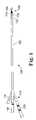
- FIG. 1is a top view of an exemplary anastomosis device of the type that can be used with the various configurations of the invention
- FIG. 2is a schematic front view of an anastomosis device having quick-disconnection capabilities as viewed within an outline of a bladder and urethra of a patient;
- FIG. 3is a schematic front view of the anastomosis device of FIG. 2 , with the proximal portion of the device detached from the distal portion of the device;
- FIG. 4is a perspective view of a portion of an anastomosis device of the type shown in FIGS. 2 and 3 , illustrating one embodiment of a configuration for providing quick-disconnection capabilities;
- FIG. 5is a cross-sectional perspective view of a portion of the anastomosis device of FIG. 4 ;
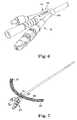
- FIG. 6is a perspective view of an end portion of an anastomosis device, including a body strap attachment feature;
- FIG. 7is a perspective view of an anastomosis device that includes the body strap attachment feature of FIG. 6 , and further including a body strap engaged with the body strap attachment feature;
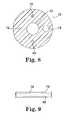
- FIG. 8is a cross-sectional end view of one embodiment of a catheter construction of the present invention.
- FIG. 9is a side view of a portion of the catheter illustrated in FIG. 8 ;
- FIG. 10is a top view of a configuration for controlling actuation wires for approximating structures of an anastomosis device, which includes a pair of screws;
- FIGS. 11-13are top views of additional configurations for controlling actuation wires for approximating structures of an anastomosis device
- FIGS. 14 and 15are top views of a configuration for activating the actuation wires that control approximating structures of an anastomosis device, which includes a “rack and pinion” type of activation;
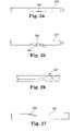
- FIG. 16is a top view of a tip configuration for use with anastomosis devices
- FIGS. 17 and 18are top views of a tip configuration for use with anastomosis devices, wherein FIG. 17 shows a tip without a guide wire and FIG. 18 shows the tip of FIG. 17 with a guide wire positioned therein;
- FIGS. 19-23illustrate top views of a device used for disengaging tissue approximating structures of an anastomosis device from the tissue they are penetrating, including a sequential representation of steps to accomplish tissue disengagement and removal of the anastomosis device;
- FIGS. 24-31illustrate top views of a revision tool used for disengaging tissue approximating structures of an anastomosis device from the tissue they are penetrating, including a sequential representation of the steps to accomplish tissue disengagement and removal of the anastomosis device.
- Device 100includes a distal end 108 , a catheter body 102 , a balloon 104 , and a drainage aperture 106 .
- Tissue approximating structurecan be located along the catheter body 102 , for example, along catheter body 102 adjacent to balloon 104 near distal end 108 .
- Tissue approximating structure of device 100is shown as two sets of tines 122 (shown in an at least partially deployed position) but may alternatively include one or more additional sets of optionally opposing tines, a different type of elongate structure such as a probe or prod or needle, a balloon, or any other structure that may be used to place or hold severed tissue in contact with another opposing severed tissue for healing.
- a different type of elongate structuresuch as a probe or prod or needle, a balloon, or any other structure that may be used to place or hold severed tissue in contact with another opposing severed tissue for healing.
- Device 100further includes proximal end 110 opposite distal end 108 .
- proximal end 110includes a port 114 that may connect to a lumen (not shown), such as an inflation lumen for balloon 104 or a drainage lumen from aperture 106 .
- a lumensuch as an inflation lumen for balloon 104 or a drainage lumen from aperture 106 .
- Another port, 116can also be used with an inflation lumen or a drainage lumen.
- Device 100further includes an actuating mechanism 120 for extending and retracting tines 122 .
- the actuating mechanismcan comprise, for example, a turnable knob or a lever (not shown), etc., that can be moved or rotated to extend or retract tines 122 .
- Other variations of these features of the illustrated proximal endwill be understood by those of skill, and may be used in combination with the features of the invention.
- FIGS. 2 and 3illustrate an embodiment of an anastomosis device 10 having a balloon 12 that is shown as being at least partially inflated, and an adjacent drainage aperture 14 .
- the balloon 12is positioned within a patient's bladder 16 and is inflated sufficiently to maintain the device 10 generally in this position when subjected to normal external forces.
- An extension portion 26extends from the balloon 12 through the patient's urethra 18 and through the urethral opening 20 .
- the extension portion 26 of device 10is preferably long enough that a proximal end 22 of device 10 can be positioned beyond the urethral opening 20 .
- any ports (e.g., a port 28 ) of the anastomosis device 10will be located outside the body when the device 10 is positioned within the patient.
- the relatively large balloon 12could be pulled into the relatively small opening of the urethra 18 . This movement of the device can cause injury to the patient and prevent the device from performing its intended function.
- tissue approximating structuresthat are being used for connecting adjacent structures or tissues (e.g., urethral and bladder tissues)
- dislodging the anastomosis devicecan also cause the tissue approximating structures to disengage from the structures or tissues they are holding together, thereby potentially causing the patient additional trauma.
- device 10is provided with quick-disconnect capabilities that allow the drainage aperture 14 , balloon 12 , and at least a part of the extension portion 26 to remain together in their original position within the patient through the use of a detachable connector 24 .
- This connector 24is positioned at some point along the length of extension portion 26 so that it can either be within the urethra 18 of the patient, as shown, or beyond the urethral opening 20 of the patient (i.e., outside the body). In either case, connector 24 is provided with sufficient attachment strength to maintain the integrity of the connection during normal movement of the patient.
- connector 24is provided with a configuration that allows for disconnection of proximal end 22 of device 10 from the remainder of the device, such as when it is subjected to a certain, predetermined force.
- the portion of device 10 that remains within the patientshould allow for generally normal functioning of the device. That is, drainage of fluids from the bladder should still be able to occur, although the same controls, ports, and other features provided by proximal end 22 of the device would not be available.
- connector 24preferably is configured to allow for reconnection of the same or a different end portion onto the portion of device 10 that remains in the patient's body.
- extension portion 26is sufficiently long to allow relatively easy access to the connector 24 after the device is positioned within the patient.
- a wide variety of configurations of such a quick-disconnect connectorsare contemplated by the invention, which may be integral parts of the body itself and/or may include separate pieces or components that are added to the device to provide such a connection between components.
- FIGS. 4 and 5illustrate one embodiment of a two-piece catheter funnel 30 that will separate under certain loading conditions to prevent these loading conditions or forces from being transmitted to the tip of the device.
- catheter funnel 30includes a main funnel portion 32 and a drain adapter 34 having a drain adapter end 36 .
- a drain(not shown) may attach to the device at this drain adapter end 36 .
- Drain adapter 34includes a quick disconnect extension 38 , which includes a neck 42 and an enlarged tip 44 .
- a mating aperture 40is provided at one end of main funnel portion 32 for engagement with extension 38 of drain adapter 34 .
- aperture 40includes a neck 46 that corresponds with neck 42 of extension 38 , and further includes an enlarged portion 48 that corresponds with enlarged tip 44 of extension 38 .
- extension 38is pressed into main funnel portion 32 at neck 46 until it is engaged within mating aperture 40 .
- enlarged tip 44 of extension 38 and neck 46 of aperture 40will be at least slightly deformable to allow the larger-sized tip 44 to pass through the smaller-sized opening of neck 46 .
- enlarged tip 44may be provided with a taper, as shown, to provide for easier passage into the aperture 40 .
- This connection between main funnel 32 and drain adapter 34is configured to be generally robust under normal movements and forces provided by patient movements. However, the sizes, shapes, materials, and other properties of these components are selected so that funnel 32 and adapter 34 will disconnect from each other when a predetermined external force is received by device 30 .
- This predetermined external forceis selected to be at least slightly less than the force required to dislodge or otherwise displace the device from the patient to avoid or minimize patient trauma.
- FIGS. 6 and 7illustrate an integrated feature on a catheter funnel that mates with a standard or custom catheter leg strap or Foley catheter holder to create additional protection from external forces on the catheter that exceed a certain level. That is, a leg strap is provided to hold the device in place relative to a patient's leg when the device is installed in a patient's body, thereby absorbing outside impacts, jerking motions, and the like, and minimizing the chances of undesirable forces being transmitted to the device. Such a leg strap may be used in addition to or instead of the quick-disconnect features described above relative to FIGS. 4 and 5 .
- FIG. 6shows one embodiment of a feature that can be used to accept or connect with a leg strap, which is illustrated with an end portion 50 of an anastomosis device or other catheter-type device.
- End portion 50includes a leg strap attachment device 52 extending from the outer surface of its main body.
- Device 52includes a body 54 having a slot 56 extending laterally through its thickness. Slot 56 is provided with a size and shape to be able to accept a strap or connector, yet is preferably provided to be as small as possible to prevent the device to which it is attached from being overly cumbersome.
- the device 52may be positioned at any point along the length of end portion 50 that corresponds with an area of the device that will be positioned outside the body of the patient when installed therein.
- Device 52is further illustrated in FIG. 7 with a stabilization or leg strap 58 that is sufficiently long to be able to encircle the leg of a patient.
- Leg strap 58further includes an auxiliary strap 62 that extends through the slot 56 of device 52 .
- Auxiliary strap 62has opposite ends that are attached to the body of strap 58 , either by one or more permanent connections or by one or more temporary connections (e.g., a hook-and-loop type of connection) to connect the strap 58 to the device 52 .
- leg strap 58can be inserted through the slot 56 without the use of an auxiliary strap 62 .
- leg strap attachment deviceswith one or more slots, clamps, or other configurations for accepting a leg strap, or the like.
- the leg strapitself is preferably made of a relatively flexible and strong material that can encircle the leg of a patient, and may be provided as a single elastic band, for example, or may have two ends 60 , 61 that are attachable to each other after the strap is positioned relative to the patient's leg.
- end 60may include a loop fastener and end 61 may include a mating hook fastener so that the ends 60 , 61 can be connected to each other by pressing them together after the strap 58 encircles the leg of a patient.
- the configuration of the leg strapshould further accommodate removal from the patient when desired, and further can include end portion attachments that can be reused multiple times, such as for repositioning or adjusting the leg strap.
- FIG. 8illustrates one manner of making a catheter using an extrusion process in order to provide a straighter catheter shaft.
- a catheter body 70which includes a generally central drainage lumen 72 , an actuation wire lumen 74 , an air lumen 76 (e.g., for balloon inflation and deflation), and a first co-extruded wire, cable or monofilament 78 .
- This catheter construction of the inventionfurther includes adding a second co-extruded wire 80 spaced on a generally opposite side of the drainage lumen 72 from the first co-extruded wire 78 , as is also illustrated in FIG. 9 .
- second wire 80may be positioned in any location in the catheter body 70 that provides a more even cooling of the structure, and therefore provides for a more straight extrusion.
- second wire 80may be coated with a non-stick material, such as a material commercially available from DuPont of Wilmington, Del., under the trade name “TEFLON”.
- a non-stick materialsuch as a material commercially available from DuPont of Wilmington, Del., under the trade name “TEFLON”.
- second wire 80can be removed from the catheter after the catheter body has hardened.
- Such wire removalis optional, but may be desirable to maintain a certain flexibility of the catheter for use during a surgical procedure. That is, second wire 80 can either be a permanent part of the catheter body construction, or may be entirely or partly removable after it has served its purpose of keeping the catheter body straight during and after the extrusion process.
- These wiresmay be made to either be removable or permanent in the catheter construction.
- FIGS. 10-15illustrate methods and devices for creating linear movement in order to activate a mechanism from a remote source. More particularly, these Figures show and describe various methods and devices that will activate linear motion in an anastomosis device so that proximal, internal approximation structures may be actuated by a distal, external control mechanism.
- the approximation structures referred to hereingenerally refer to bladder tines and urethral tines, where any of the activation devices can be used to equally refer to either or both of these types of tines.
- each set of tineswill be specifically structured for connection to that tissue.
- Device 130can be located, for example, generally at the proximal end of an anastomosis device, such as at the proximal end 110 of the device 100 of FIG. 1 .
- Device 130is a screw drive for moving the actuation wires linearly, and generally comprises a first screw 132 , a second screw 134 , a first block 136 , a second block 138 , a first actuation wire 140 , and a second actuation wire 142 .
- First and second actuation wires 140 , 142are attached to separate approximation structures (not shown) that are located remotely from the activation device 130 .
- First screw 132is locked to first block 136 with a pair of bolts 144 , 146 , positioned on opposite sides of block 136 , although it is possible that the first screw 132 is fixed to first block 136 using a different type of connection configuration.
- First screw 132is threaded along its length and second block 138 includes a threaded opening (not visible) for engagement with the threads of first screw 132 .
- Second block 138further includes a non-threaded hole (not visible) through which the second screw 134 extends, and first block 136 includes a threaded hole (not visible) for engagement with the threads of second screw 134 .
- First actuation wire 140is attached to first block 136
- second actuation wire 142extends through a hole in first block 136 and is attached to second block 138 .
- first screw 132will move first block 136 laterally relative to the length of screw 132 , thereby moving actuation wire 140 in a direction that is generally parallel to the length of screw 132 .
- second block 138will remain stationary.
- rotation of second screw 134will move second block 138 laterally relative to the length of screw 134 , thereby moving actuation wire 142 , which is attached to second block 138 , in a direction that is generally parallel to the length of second screw 134 .
- Screws 132 , 134can be rotated through the use of either a manual driver or an automatic driver to move the actuation wires 140 , 142 , respectively, thereby retracting or withdrawing approximation structures remotely located from the device 130 .
- two sets of approximation structurese.g., bladder tines and urethral tines
- FIGS. 11-13illustrate embodiments of activation devices that can be located generally at the proximal end of an anastomosis device, such as at the proximal end 110 of the device 100 of FIG. 1 .
- All of these devicesinclude the use of advancement structures or devices that “pull” an actuation wire to deploy one approximation structure (e.g., bladder tines) and “push” an actuation wire to deploy another approximation structure (e.g., urethral tines).
- the opposite actionis performed with the advancement structures or devices (e.g., pulling instead of pushing, and vice versa).
- FIG. 11illustrates a catheter body 148 from which an activation device 150 extends.
- Device 150generally includes a first arm 152 connected to a first actuation wire 154 , and a second arm 156 connected to a second actuation wire 158 . Both arms 152 and 156 are slideably mounted to a plate 160 , which may include channels in which arms 152 , 156 are positioned. Arms 152 , 156 are independently moveable to push or pull their respective actuation wires, which in turn will deploy or retract the approximation structures that are remotely located relative to the device 150 .
- Device 150can further include one or more locking members 162 for maintaining arms 152 , 156 in place once the actuation wires 154 , 158 have been moved or slid into their desired positions.
- locking members 162are in the form of buttons that can be pressed downwardly to put pressure on their respective arms 152 , 156 within the channels in the plate 160 and lock them in place. The locking members 162 may then be at least partially released when it is desired to allow arms 152 , 156 to be repositioned. This sequence can be repeated multiple times during the process of deploying and retracting approximation structures, if needed or desired.
- FIG. 12illustrates an activation device 170 that generally includes a first mechanism 172 connected to a first actuation wire 176 , and a second mechanism 174 connected to a second actuation wire 178 .
- mechanism 172is shown as being shaded in the figure, and mechanism 174 is not shaded.
- Both mechanisms 172 and 174are slideably mounted within a recess of a casing 180 , which may include channels in which portions of mechanisms 172 , 174 are positioned, or may include other guiding devices.
- Mechanism 172includes a base 181 connected to a release button 182 via at least one connector arm
- mechanism 174includes a base 183 connected to a release button 184 via at least one connector arm.
- release button 182is squeezed toward the center of the casing 180 and toward base portion 181 , and then the mechanism 172 can be moved along the length of the casing 180 by a desired distance.
- release button 184is squeezed toward the center of casing 180 and toward base portion 183 , and then the mechanism 174 can be moved along the length of the casing 180 by a desired distance.
- Mechanisms 172 , 174are independently moveable to push or pull their respective actuation wires, which in turn will deploy or retract the approximation structures that are remotely located relative to the device 170 .
- Device 170can further include a cover 186 that is connected to casing 180 via a hinge 185 .
- Cover 186can be used for maintaining mechanisms 172 , 174 in place once the actuation wires 176 , 178 have been moved or slid into their desired positions.
- Cover 186may further be used to verify that the mechanisms 172 , 174 are in a certain position, since the cover 186 will interfere with release buttons 182 , 184 in certain arrangements of the components.
- cover 186can only close when the buttons of the mechanisms 172 , 174 are in a certain position, such as when the actuation wires are deployed. In this way, a health provider and the patient can be sure that the actuation wires are properly positioned and that they will stay in that position once cover 186 is closed.
- FIG. 13Another activation device 190 is illustrated in FIG. 13 , which is similar in operation to the device 150 of FIG. 11 .
- Activation device 190extends from a catheter body 191 , and generally includes a first button 192 connected to a first actuation wire 194 , and a second button 196 connected to a second actuation wire 198 .
- Both buttons 192 and 196are slideably mounted to a plate 199 , which may include channels in which buttons 192 , 196 and/or actuation wires 194 , 198 are positioned.
- Buttons 192 , 196are independently moveable to push or pull their respective actuation wires, which in turn will deploy or retract the approximation structures that are remotely located relative to the device 190 .
- Device 190can further include one or more locking members (not shown) for maintaining arms 192 , 196 in place once the actuation wires 194 , 198 have been moved or slid into their desired positions.
- FIGS. 14 and 15illustrate additional alternative embodiments of activation devices that would be located generally at the proximal end of an anastomosis device, such as at the proximal end 110 of the device 100 of FIG. 1 .
- These devicesare somewhat similar to those of FIGS. 11-13 in that they also use the motions of pushing and pulling actuation wires to deploy and retract approximation structures. However, these devices utilize a rack and pinion type of arrangement of gears that effectively push and pull the advancement arms.
- FIG. 14shows an activation device 200 that includes a base plate 202 on which a first rack 204 and a second rack 206 are mounted.
- First rack 202is connected to a first actuation wire 208 and second rack 206 is connected to a second actuation wire 210 .
- Device 200further includes a first wheel gear 212 and a second wheel gear 214 that mesh with the teeth of first and second racks 202 , 206 , respectively. Rotation of the first wheel gear 212 thereby moves the rack 202 back and forth due to the engagement of the wheel gear 212 with the rack 202 , which causes a corresponding movement of the first actuation wire 208 . Similarly, rotation of the second wheel gear 214 moves the second rack 206 back and forth due to the engagement of the wheel gear 214 with the rack 206 , which causes a corresponding movement of the second actuation wire 210 . Because two wheel gears 212 , 214 are used in this embodiment, the actuation wires can be operated independently for separate deployment and retraction of approximation structures.
- FIG. 15illustrates an activation device 250 that again utilizes the concept of a rack and pinion configuration for controlling the movement of one of the actuation wires.
- Activation device 250includes a base plate 252 on which a rack and pinion structure 254 is mounted.
- Structure 254includes a first rack 256 , a second rack 258 that is connected to a first actuation wire 260 , and a gear 262 positioned to engage with the gears of both racks 256 , 258 .
- Rack 256further includes an arm 264 that can be grasped for pulling or pushing to move the actuation wire 260 .
- Activation device 250further includes an arm 266 connected to a second actuation wire 268 .
- Arm 266may be slideably mounted to plate 252 , which may include a channel in which arm 266 is positioned. Arm 266 may be lockable with a locking mechanism 270 .
- the device 250may instead include a different configuration for movement of wire 268 than the arm 266 , such as another rack and gear configuration similar to that of structure 254 .
- the actuation wires 260 , 268are independently moveable to push or pull their respective actuation wires, which in turn will deploy or retract the approximation structures that are remotely located relative to the device 250 .
- a number of other conceptsare contemplated to create linear movement in order to activate a mechanism from a remote source.
- the following concepts for various methods and devicesare useful to activate linear motion in an anastomosis device so that the proximal, internal approximation structures may be actuated by a distal, external control mechanism.
- One such concept of the inventionrelates to a detachable actuation mechanism that can be detached from the main body of the device after actuation has been achieved. The benefit of this design would be that individuals (e.g., patients) could not manipulate the device once placed. To remove the device, the actuation mechanism could be reattached to the main body.
- a balloon inflation valvecan be incorporated into the actuation mechanism such that a preferential sequencing could be directed.
- the preferred sequencingwould be to inflate the bladder balloon, actuate the bladder tines, and then actuate the urethral tines. After deploying the tines, the balloon inflation valve would be “locked out” until the tines have been retracted. This design feature may prevent mistaken removal of the device prior to complete tine retraction.
- a separate actuation wirecan be provided in the device for each set of tissue approximating structures to allow for independent extension and retraction of the tissue approximating structures, as desired. That is, individual components of a specific approximation structure can be activated independently of the other components of the same approximation structure.
- both of the actuation wirescan be connected within a single actuation mechanism that can be manipulated to provide the desired movement of the tissue approximating structures.
- the anastomosis devices of the inventionmay be provided with various tip configurations relative to the delivery and/or exchange of the device, which may be used with the type of device illustrated in FIG. 1 , for example.
- the tipcan be curved into a configuration known as a coude configuration to generally match the curvature of the patient's anatomy and ease the delivery of the device.
- a coude tipis illustrated in FIG. 16 .
- a tip 230comprises a curved portion 232 that extends from a relatively spherical end portion 234 . This configuration provides for easier insertion of the device with less potential trauma to the patient.
- a devicemay be provided with a council tip to ease in the exchange of the device in the event that an original device needs to be removed, such as is illustrated in FIGS. 17 and 18 .
- a tip 240includes a drainage aperture 242 and a hole 244 at its end to accommodate a guide wire 246 , which is illustrated in FIG. 18 .
- the use of such a guide wirecan aid in the maneuverability of the device to difficult areas of the patient's anatomy.
- anastomosis devices described hereinmay be provided for the anastomosis devices described herein, or for other anastomosis devices.
- One such featureinvolves providing a lubricious coating to ease the delivery and/or exchange of the device.
- the coatingcan be covalently or non-covalently bonded.
- the devicecan be provided in a pre-coated form, or may instead be coated at the time of usage.
- Another featureis to provide an anastomosis device with an antimicrobial coating on a portion or on the entire device. Such a coating can reduce the likelihood of a urinary tract infection.
- Another featureis to deliver therapeutic agents via the anastomosis device. Methods of achieving this function can include utilizing needles as approximation structures, adding an additional lumen to administrate drug delivery while the device is placed, or incorporating a drug release mechanism on portions of the device.
- FIGS. 19-31describe methods and devices that can be used in conjunction with an anastomosis device in the event that the urethral or bladder tines do not fully retract to disengage from the tissue of the patient, or in a case where the actuation mechanism becomes disconnected when the device is in the patient's body.
- FIGS. 19-23illustrate the steps of removing the anastomosis device with a resectoscope sheath for cases where the tines do not fully retract or become disconnected from their control mechanism.
- FIG. 19shows a catheter tube 300 having two sets of deployed tines 302 , 304 .
- a representative proximal end portion 306 having an actuation mechanism 308is also shown, as an illustration of the disconnection of the tines from an actuation mechanism.
- the balloon of catheter tube 300would likely deflate, as shown, upon disconnection of the proximal end portion 306 .
- a representative resectoscope 310 that will be used to change the configuration of the deployed tinesis shown, which has a diameter that is at least slightly larger than the outer diameter of catheter tube 300 .
- Resectoscope 310is slid onto the end of tube 300 opposite the tip of the device, until it contacts the tines 304 (e.g., the urethral tines), as shown in FIG. 20 .
- the catheter tube 300is then pulled toward resectoscope 310 while maintaining the position of resectoscope 310 to minimize trauma to the surrounding urethral tissue, as shown in FIG. 21 .
- Tines 304will then be positioned within the interior area of resectoscope 310 .
- the catheter tube 300is then pulled further toward resectoscope 310 until it contacts the tines 302 (e.g., the bladder tines), as illustrated in FIG. 22 .
- Catheter tube 300is pulled even further toward resectoscope 310 until tines 302 are also enclosed within the interior area of resectoscope 310 , as shown in FIG. 23 . At this point, the tines 302 , 304 are no longer engaged with any tissue, and in fact are partially or completely enclosed within resectoscope 310 . The resectoscope/catheter tube assembly can then be removed from the patient without causing trauma to the surrounding tissue.
- FIGS. 24-27illustrate the steps of another method of removing the removing the anastomosis device with a custom revision tool for cases where the tines do not fully retract or become disconnected. These steps can be performed blindly, or may be performed using visualization techniques, such as fluoroscopy, ultrasound, and the like.
- a revision tool 320is shown, which is chosen to be a size that will fit within the central drainage lumen of a catheter. That is, the revision tool 320 consists of an outer sheath that has an outside diameter that is smaller than the inside dimension of the anastomosis device. The tip of the outer sheath is blunt and has a side hole 322 a short distance from the tip.
- Revision tool 320further includes an inner tube with a cutting mechanism 324 , which is illustrated in FIGS. 25 and 26 .
- Cutting mechanism 324is also visible in FIG. 27 , which shows cutting mechanism 324 penetrating the wall of a flexible core tubing 326 in which the revision tool 320 is inserted.
- the toolis used to cut through the flexible core tubing 326 of the anastomosis device from within the device.
- the toolcan further be used to attach to the individual hubs in order to retract the tines, as described in further detail below.
- FIGS. 28-29illustrate a method for retracting bladder tines 328 , which are arranged about a hub 330 .
- a revision toolis inserted within tube 326 , and when the tool is in the correct position, cutting mechanism 324 is used to penetrate tube 326 at the desired place relative to the tines 328 .
- the revision toolis then moved relative to tube 326 so that cutting mechanism 324 will push the hub 330 laterally, thereby retracting the bladder tines.
- FIGS. 30-31illustrate a method of retracting urethral tines 340 , which are arranged about a hub 342 .
- a revision toolis inserted within tube 326 , and when the tool is in the correct position, cutting mechanism 344 is used to penetrate tube 326 at the desired place relative to the tines 340 .
- the revision toolis then moved relative to tube 326 so that cutting mechanism 244 will push the hub 340 in essentially an opposite direction from that described above relative to FIGS. 28 and 29 , thereby retracting the urethral tines.
Landscapes
- Health & Medical Sciences (AREA)
- Life Sciences & Earth Sciences (AREA)
- Surgery (AREA)
- Heart & Thoracic Surgery (AREA)
- Engineering & Computer Science (AREA)
- Biomedical Technology (AREA)
- Nuclear Medicine, Radiotherapy & Molecular Imaging (AREA)
- Medical Informatics (AREA)
- Molecular Biology (AREA)
- Animal Behavior & Ethology (AREA)
- General Health & Medical Sciences (AREA)
- Public Health (AREA)
- Veterinary Medicine (AREA)
- Surgical Instruments (AREA)
Abstract
Description
Claims (4)
Priority Applications (2)
| Application Number | Priority Date | Filing Date | Title |
|---|---|---|---|
| US11/437,963US7717928B2 (en) | 2005-05-20 | 2006-05-19 | Anastomosis device configurations and methods |
| US12/721,722US8277467B2 (en) | 2005-05-20 | 2010-03-11 | Anastomosis device configurations and methods |
Applications Claiming Priority (2)
| Application Number | Priority Date | Filing Date | Title |
|---|---|---|---|
| US68294405P | 2005-05-20 | 2005-05-20 | |
| US11/437,963US7717928B2 (en) | 2005-05-20 | 2006-05-19 | Anastomosis device configurations and methods |
Related Child Applications (1)
| Application Number | Title | Priority Date | Filing Date |
|---|---|---|---|
| US12/721,722DivisionUS8277467B2 (en) | 2005-05-20 | 2010-03-11 | Anastomosis device configurations and methods |
Publications (2)
| Publication Number | Publication Date |
|---|---|
| US20060276811A1 US20060276811A1 (en) | 2006-12-07 |
| US7717928B2true US7717928B2 (en) | 2010-05-18 |
Family
ID=37495122
Family Applications (2)
| Application Number | Title | Priority Date | Filing Date |
|---|---|---|---|
| US11/437,963Active2028-09-02US7717928B2 (en) | 2005-05-20 | 2006-05-19 | Anastomosis device configurations and methods |
| US12/721,722Expired - Fee RelatedUS8277467B2 (en) | 2005-05-20 | 2010-03-11 | Anastomosis device configurations and methods |
Family Applications After (1)
| Application Number | Title | Priority Date | Filing Date |
|---|---|---|---|
| US12/721,722Expired - Fee RelatedUS8277467B2 (en) | 2005-05-20 | 2010-03-11 | Anastomosis device configurations and methods |
Country Status (1)
| Country | Link |
|---|---|
| US (2) | US7717928B2 (en) |
Cited By (4)
| Publication number | Priority date | Publication date | Assignee | Title |
|---|---|---|---|---|
| US20070102170A1 (en)* | 2005-11-09 | 2007-05-10 | Waldack Larry E | Crimp Hub for Anastomosis Device |
| US20110118767A1 (en)* | 2008-07-30 | 2011-05-19 | Ams Research Corporation | Method and Apparatus for Determining Status of Approximation Structures on Anastomosis Device |
| US8747386B2 (en) | 2010-12-16 | 2014-06-10 | Ams Research Corporation | Anastomosis device and related methods |
| US11896229B2 (en) | 2020-09-01 | 2024-02-13 | Boston Scientific Scimed, Inc. | Grappling systems and methods for lumen apposition or wound defects |
Families Citing this family (19)
| Publication number | Priority date | Publication date | Assignee | Title |
|---|---|---|---|---|
| US20060099993A1 (en)* | 2004-11-05 | 2006-05-11 | Nokia Corporation | Multiple antenna portable hand-held electronic device |
| US8636756B2 (en) | 2005-02-18 | 2014-01-28 | Ams Research Corporation | Anastomosis device and surgical tool actuation mechanism configurations |
| US8066725B2 (en)* | 2006-10-17 | 2011-11-29 | Ams Research Corporation | Anastomosis device having improved safety features |
| US7993264B2 (en)* | 2006-11-09 | 2011-08-09 | Ams Research Corporation | Orientation adapter for injection tube in flexible endoscope |
| US8277466B2 (en) | 2006-11-14 | 2012-10-02 | Ams Research Corporation | Anastomosis device and method |
| US20080140098A1 (en)* | 2006-11-15 | 2008-06-12 | Monica Kumar | Anastomosis Balloon Configurations and device |
| US8491525B2 (en)* | 2006-11-17 | 2013-07-23 | Ams Research Corporation | Systems, apparatus and associated methods for needleless delivery of therapeutic fluids |
| US20080119729A1 (en)* | 2006-11-22 | 2008-05-22 | Copa Vincent G | Built-In Balloon Actuator for Urological Device |
| US20080167526A1 (en)* | 2007-01-08 | 2008-07-10 | Crank Justin M | Non-Occlusive, Laterally-Constrained Injection Device |
| US7850649B2 (en) | 2007-11-09 | 2010-12-14 | Ams Research Corporation | Mechanical volume control for injection devices |
| US20100030139A1 (en)* | 2008-07-30 | 2010-02-04 | Copa Vincent G | Anastomosis Devices and Methods Utilizing Colored Bands |
| US8388349B2 (en) | 2009-01-14 | 2013-03-05 | Ams Research Corporation | Anastomosis deployment force training tool |
| US20110160754A1 (en)* | 2009-12-30 | 2011-06-30 | Crank Justin M | Spring-loaded anastomosis device and method |
| US20120158025A1 (en)* | 2010-12-15 | 2012-06-21 | Christopher Anderson | Anastomosis device and related methods |
| AU2011343593B2 (en) | 2010-12-16 | 2016-02-25 | Boston Scientific Scimed, Inc. | Micro-needle bladder balloon |
| US8992427B2 (en) | 2012-09-07 | 2015-03-31 | Gynesonics, Inc. | Methods and systems for controlled deployment of needle structures in tissue |
| EP2870979B1 (en) | 2013-11-08 | 2021-01-06 | Nuvectra Corporation | Implantable medical lead for stimulation of multiple nerves |
| US9931133B2 (en)* | 2016-03-24 | 2018-04-03 | A.M. Surgical, Inc. | Compact endoscopic surgical device and method of use thereof |
| CN115715689B (en) | 2016-11-11 | 2025-01-17 | 杰尼索尼克斯公司 | Tissue controlled treatment and dynamic interaction and comparison with tissue and/or treatment data |
Citations (70)
| Publication number | Priority date | Publication date | Assignee | Title |
|---|---|---|---|---|
| US1411175A (en)* | 1921-05-25 | 1922-03-28 | Maguire Margaret | Book carrier |
| US1803048A (en)* | 1928-12-26 | 1931-04-28 | Weldon E Allen | Hopple |
| US2966905A (en)* | 1957-04-08 | 1961-01-03 | Rehabilitation Res Products | Ambulation training apparatus |
| US3196870A (en)* | 1962-05-08 | 1965-07-27 | Lebanon Machine & Mfg Co Inc | Limb immobilizer for intravenous feeding or the like |
| US3640273A (en)* | 1970-03-13 | 1972-02-08 | Tommy D Ray | Strap assembly for securing a patient{40 s arm to an arm board |
| US3947927A (en)* | 1974-08-26 | 1976-04-06 | Rosenthal Allen M | Ski tie |
| US3994048A (en)* | 1974-08-26 | 1976-11-30 | Rosenthal Allen M | Tie |
| US4701162A (en) | 1985-09-24 | 1987-10-20 | The Kendall Company | Foley catheter assembly |
| US4705502A (en) | 1985-11-06 | 1987-11-10 | The Kendall Company | Suprapubic catheter with dual balloons |
| US4792330A (en) | 1987-07-13 | 1988-12-20 | Lazarus Medical Innovations, Inc. | Combination catheter and duct clamp apparatus and method |
| US4848367A (en) | 1987-02-11 | 1989-07-18 | Odis L. Avant | Method of effecting dorsal vein ligation |
| US4873977A (en) | 1987-02-11 | 1989-10-17 | Odis L. Avant | Stapling method and apparatus for vesicle-urethral re-anastomosis following retropubic prostatectomy and other tubular anastomosis |
| US4909785A (en) | 1986-03-25 | 1990-03-20 | American Medical Systems, Inc. | Method for valving body fluids |
| US4911164A (en) | 1988-04-26 | 1990-03-27 | Roth Robert A | Surgical tool and method of use |
| US4932956A (en) | 1988-05-10 | 1990-06-12 | American Medical Systems, Inc. | Prostate balloon dilator |
| US5047039A (en) | 1990-09-14 | 1991-09-10 | Odis Lynn Avant | Method and apparatus for effecting dorsal vein ligation and tubular anastomosis and laparoscopic prostatectomy |
| US5123908A (en) | 1989-01-26 | 1992-06-23 | Chen Fusen H | Anastomotic device |
| US5152772A (en) | 1991-07-10 | 1992-10-06 | Sewell Jr Frank | Sphincterotomy catheter and method |
| US5211649A (en)* | 1987-02-10 | 1993-05-18 | Vaso Products Australia Pty. Limited | Venous cuff applicator, cartridge and cuff |
| WO1996007447A1 (en) | 1994-09-02 | 1996-03-14 | Mauro Dimitri | Drainage catheter for urinary neo-bladders |
| US5540701A (en) | 1994-05-20 | 1996-07-30 | Hugh Sharkey | Passive fixation anastomosis method and device |
| US5545171A (en) | 1994-09-22 | 1996-08-13 | Vidamed, Inc. | Anastomosis catheter |
| US5582337A (en)* | 1995-06-20 | 1996-12-10 | Mcpherson; Mathew A. | Strap system for carrying skates and shoes and method of use |
| US5695504A (en) | 1995-02-24 | 1997-12-09 | Heartport, Inc. | Devices and methods for performing a vascular anastomosis |
| US5707380A (en) | 1996-07-23 | 1998-01-13 | United States Surgical Corporation | Anastomosis instrument and method |
| US5833698A (en) | 1996-07-23 | 1998-11-10 | United States Surgical Corporation | Anastomosis instrument and method |
| WO1999016359A1 (en) | 1997-09-26 | 1999-04-08 | Cryolife, Inc. | Sutureless anastomotic technique using a bioadhesive and device therefor |
| WO1999021491A1 (en) | 1997-10-24 | 1999-05-06 | Suyker Wilhelmus Jospeh Leonar | Mechanical anastomosis system for hollow structures |
| WO1999021490A1 (en) | 1997-06-28 | 1999-05-06 | Transvascular, Inc. | Transluminal methods and apparatus for closing, forming attachments to, and/or forming anastomotic junctions in, luminal anatomical structures |
| US5931842A (en) | 1996-11-07 | 1999-08-03 | Vascular Science Inc. | Methods and apparatus for handling tubing used in medical procedures |
| US5964791A (en) | 1995-05-18 | 1999-10-12 | Prostalund Operations Ab | Apparatus for heat treatment of tissue |
| WO1999058081A2 (en) | 1998-05-11 | 1999-11-18 | Hovland Claire T | Devices and methods for treating e.g. urinary stress incontinence |
| US6024748A (en) | 1996-07-23 | 2000-02-15 | United States Surgical Corporation | Singleshot anastomosis instrument with detachable loading unit and method |
| US6119045A (en) | 1995-05-12 | 2000-09-12 | Prostalund Operations Ab | Device for maintaining a passage for urine through the prostate |
| US6138882A (en)* | 1999-08-23 | 2000-10-31 | Buettner; Dale T. | Universal carrier for bottles, beverage containers and other projects |
| US6193734B1 (en) | 1998-01-23 | 2001-02-27 | Heartport, Inc. | System for performing vascular anastomoses |
| US6238368B1 (en) | 1994-07-13 | 2001-05-29 | Marian Devonec | Therapeutic device for the selective cytoreduction treatment of an obstruction |
| US6254570B1 (en) | 1997-04-07 | 2001-07-03 | Vance Products, Inc. | Back-up retention member drainage catheter |
| US6299598B1 (en) | 1997-02-04 | 2001-10-09 | Cook Urological, Incorporated | Drainage catheter |
| US20010049492A1 (en) | 1999-09-20 | 2001-12-06 | Frazier Andrew G.C. | Anastomosis catheter |
| US20020002363A1 (en) | 2000-04-27 | 2002-01-03 | Ryuichi Urakawa | Catheter and medical tube |
| US6391039B1 (en) | 1996-07-23 | 2002-05-21 | United States Surgical Corporation | Anastomosis instrument and method |
| US20020087176A1 (en) | 2000-10-10 | 2002-07-04 | Greenhalgh E. Skott | Anastomosis device |
| US6416545B1 (en) | 1996-04-09 | 2002-07-09 | Endocare, Inc. | Urological stent therapy system and method |
| US6440146B2 (en) | 1996-07-23 | 2002-08-27 | United States Surgical Corporation | Anastomosis instrument and method |
| US6447533B1 (en) | 1998-05-26 | 2002-09-10 | Scimed Life Systems, Inc. | Implantable tissue fastener and system for treating gastroesophageal reflux disease |
| US6461367B1 (en) | 1999-07-16 | 2002-10-08 | Loma Linda University Medical Center | Method and device for urethral-vesicle anastomosis |
| US6494908B1 (en) | 1999-12-22 | 2002-12-17 | Ethicon, Inc. | Removable stent for body lumens |
| US6520974B2 (en) | 1997-06-30 | 2003-02-18 | Eva Corporation | Surgical fastener |
| US6530932B1 (en) | 2000-08-30 | 2003-03-11 | Ethicon Endo-Surgery, Inc. | Anastomosis device having improved tissue presentation |
| US20030069629A1 (en) | 2001-06-01 | 2003-04-10 | Jadhav Balkrishna S. | Bioresorbable medical devices |
| US6562024B2 (en) | 1997-08-14 | 2003-05-13 | Scimed Life Systems, Inc. | Drainage catheter delivery system |
| US6602243B2 (en) | 2000-12-15 | 2003-08-05 | Alsius Corporation | Foley catheter having redundant temperature sensors and method |
| US20030208183A1 (en) | 2000-08-07 | 2003-11-06 | Whalen Mark J. | Endourethral device & method |
| US20030229364A1 (en) | 2002-06-11 | 2003-12-11 | Michael Seiba | Device for anastomosis in a radical retropubic prostatectomy |
| WO2004000138A1 (en) | 2002-06-19 | 2003-12-31 | Tyco Healthcare Group Lp | Method and apparatus for anastomosis |
| WO2004000135A2 (en) | 2002-06-20 | 2003-12-31 | Tyco Healthcare Group, Lp | Method and apparatus for anastomosis including an anchoring sleeve |
| WO2004000136A2 (en) | 2002-06-20 | 2003-12-31 | Tyco Healthcare Group, Lp | Method and apparatus for anastomosis including an anchoring sleeve |
| WO2004000137A2 (en) | 2002-06-19 | 2003-12-31 | Tyco Healthcare Group Lp | Method and apparatus for radical prostatectomy anastomosis |
| US6676674B1 (en)* | 1999-03-17 | 2004-01-13 | Moshe Dudai | Gastric band |
| US6695832B2 (en) | 2000-06-01 | 2004-02-24 | Twincath, Llc | Multilumen catheter and methods for making the catheter |
| US6719749B1 (en) | 2000-06-01 | 2004-04-13 | Medical Components, Inc. | Multilumen catheter assembly and methods for making and inserting the same |
| US6719709B2 (en)* | 2000-08-31 | 2004-04-13 | Abbeymoor Medical, Inc. | Diagnostic urethral assembly and method |
| WO2004034913A1 (en) | 2002-10-16 | 2004-04-29 | Civco Medical Instruments Inc. | Suturing system and method |
| US20040087995A1 (en)* | 2002-08-22 | 2004-05-06 | Copa Vincent G. | Anastomosis device and related methods |
| US6740098B2 (en) | 1998-05-11 | 2004-05-25 | Surgical Connections, Inc. | Surgical stabilizer devices and methods |
| US6746456B2 (en) | 2001-09-28 | 2004-06-08 | Ethicon, Inc. | Needle array suturing/sewing anastomosis device and method for anastomosis |
| US20050070938A1 (en) | 2002-08-22 | 2005-03-31 | Copa Vincent G. | Anastomosis device and related methods |
| US20050131431A1 (en)* | 2002-08-22 | 2005-06-16 | Copa Vincent G. | Anastomosis device and related methods |
| US7402147B1 (en)* | 2000-11-17 | 2008-07-22 | Susan Davis Allen | Body limb movement limiter |
Family Cites Families (2)
| Publication number | Priority date | Publication date | Assignee | Title |
|---|---|---|---|---|
| US6440533B1 (en)* | 2000-09-22 | 2002-08-27 | Tredegar Film Products Corporation | PVC replacement film |
| US20050121431A1 (en)* | 2003-12-05 | 2005-06-09 | Yuen Se K. | Micro computer thermal mug |
- 2006
- 2006-05-19USUS11/437,963patent/US7717928B2/enactiveActive
- 2010
- 2010-03-11USUS12/721,722patent/US8277467B2/ennot_activeExpired - Fee Related
Patent Citations (79)
| Publication number | Priority date | Publication date | Assignee | Title |
|---|---|---|---|---|
| US1411175A (en)* | 1921-05-25 | 1922-03-28 | Maguire Margaret | Book carrier |
| US1803048A (en)* | 1928-12-26 | 1931-04-28 | Weldon E Allen | Hopple |
| US2966905A (en)* | 1957-04-08 | 1961-01-03 | Rehabilitation Res Products | Ambulation training apparatus |
| US3196870A (en)* | 1962-05-08 | 1965-07-27 | Lebanon Machine & Mfg Co Inc | Limb immobilizer for intravenous feeding or the like |
| US3640273A (en)* | 1970-03-13 | 1972-02-08 | Tommy D Ray | Strap assembly for securing a patient{40 s arm to an arm board |
| US3947927A (en)* | 1974-08-26 | 1976-04-06 | Rosenthal Allen M | Ski tie |
| US3994048A (en)* | 1974-08-26 | 1976-11-30 | Rosenthal Allen M | Tie |
| US4701162A (en) | 1985-09-24 | 1987-10-20 | The Kendall Company | Foley catheter assembly |
| US4705502A (en) | 1985-11-06 | 1987-11-10 | The Kendall Company | Suprapubic catheter with dual balloons |
| US4909785A (en) | 1986-03-25 | 1990-03-20 | American Medical Systems, Inc. | Method for valving body fluids |
| US5211649A (en)* | 1987-02-10 | 1993-05-18 | Vaso Products Australia Pty. Limited | Venous cuff applicator, cartridge and cuff |
| US4848367A (en) | 1987-02-11 | 1989-07-18 | Odis L. Avant | Method of effecting dorsal vein ligation |
| US4873977A (en) | 1987-02-11 | 1989-10-17 | Odis L. Avant | Stapling method and apparatus for vesicle-urethral re-anastomosis following retropubic prostatectomy and other tubular anastomosis |
| US4792330A (en) | 1987-07-13 | 1988-12-20 | Lazarus Medical Innovations, Inc. | Combination catheter and duct clamp apparatus and method |
| US4911164A (en) | 1988-04-26 | 1990-03-27 | Roth Robert A | Surgical tool and method of use |
| US4932956A (en) | 1988-05-10 | 1990-06-12 | American Medical Systems, Inc. | Prostate balloon dilator |
| US5123908A (en) | 1989-01-26 | 1992-06-23 | Chen Fusen H | Anastomotic device |
| US5047039A (en) | 1990-09-14 | 1991-09-10 | Odis Lynn Avant | Method and apparatus for effecting dorsal vein ligation and tubular anastomosis and laparoscopic prostatectomy |
| WO1992004869A1 (en) | 1990-09-14 | 1992-04-02 | Avant Odis L | A method and apparatus for effecting dorsal vein ligation |
| US5152772A (en) | 1991-07-10 | 1992-10-06 | Sewell Jr Frank | Sphincterotomy catheter and method |
| US5540701A (en) | 1994-05-20 | 1996-07-30 | Hugh Sharkey | Passive fixation anastomosis method and device |
| US6238368B1 (en) | 1994-07-13 | 2001-05-29 | Marian Devonec | Therapeutic device for the selective cytoreduction treatment of an obstruction |
| WO1996007447A1 (en) | 1994-09-02 | 1996-03-14 | Mauro Dimitri | Drainage catheter for urinary neo-bladders |
| US5545171A (en) | 1994-09-22 | 1996-08-13 | Vidamed, Inc. | Anastomosis catheter |
| US5695504A (en) | 1995-02-24 | 1997-12-09 | Heartport, Inc. | Devices and methods for performing a vascular anastomosis |
| US6119045A (en) | 1995-05-12 | 2000-09-12 | Prostalund Operations Ab | Device for maintaining a passage for urine through the prostate |
| US5964791A (en) | 1995-05-18 | 1999-10-12 | Prostalund Operations Ab | Apparatus for heat treatment of tissue |
| US5582337A (en)* | 1995-06-20 | 1996-12-10 | Mcpherson; Mathew A. | Strap system for carrying skates and shoes and method of use |
| US6416545B1 (en) | 1996-04-09 | 2002-07-09 | Endocare, Inc. | Urological stent therapy system and method |
| US6440146B2 (en) | 1996-07-23 | 2002-08-27 | United States Surgical Corporation | Anastomosis instrument and method |
| US20040078047A1 (en) | 1996-07-23 | 2004-04-22 | Nicholas David A. | Anastomosis instrument and method |
| US6726697B2 (en) | 1996-07-23 | 2004-04-27 | United States Surgical Corporation | Anastomosis instrument and method |
| US6024748A (en) | 1996-07-23 | 2000-02-15 | United States Surgical Corporation | Singleshot anastomosis instrument with detachable loading unit and method |
| US5833698A (en) | 1996-07-23 | 1998-11-10 | United States Surgical Corporation | Anastomosis instrument and method |
| US6391039B1 (en) | 1996-07-23 | 2002-05-21 | United States Surgical Corporation | Anastomosis instrument and method |
| US5707380A (en) | 1996-07-23 | 1998-01-13 | United States Surgical Corporation | Anastomosis instrument and method |
| US5931842A (en) | 1996-11-07 | 1999-08-03 | Vascular Science Inc. | Methods and apparatus for handling tubing used in medical procedures |
| US6302905B1 (en) | 1996-11-07 | 2001-10-16 | St. Jude Medical Cardiovascular Group Inc. | Medical grafting methods and apparatus |
| US6299598B1 (en) | 1997-02-04 | 2001-10-09 | Cook Urological, Incorporated | Drainage catheter |
| US6254570B1 (en) | 1997-04-07 | 2001-07-03 | Vance Products, Inc. | Back-up retention member drainage catheter |
| WO1999021490A1 (en) | 1997-06-28 | 1999-05-06 | Transvascular, Inc. | Transluminal methods and apparatus for closing, forming attachments to, and/or forming anastomotic junctions in, luminal anatomical structures |
| US6520974B2 (en) | 1997-06-30 | 2003-02-18 | Eva Corporation | Surgical fastener |
| US6562024B2 (en) | 1997-08-14 | 2003-05-13 | Scimed Life Systems, Inc. | Drainage catheter delivery system |
| WO1999016359A1 (en) | 1997-09-26 | 1999-04-08 | Cryolife, Inc. | Sutureless anastomotic technique using a bioadhesive and device therefor |
| US6485496B1 (en) | 1997-10-24 | 2002-11-26 | Wilhelmus Joseph Leonardus Suyker | Mechanical anastomosis system for hollow structures |
| WO1999021491A1 (en) | 1997-10-24 | 1999-05-06 | Suyker Wilhelmus Jospeh Leonar | Mechanical anastomosis system for hollow structures |
| US6193734B1 (en) | 1998-01-23 | 2001-02-27 | Heartport, Inc. | System for performing vascular anastomoses |
| US6149667A (en) | 1998-05-11 | 2000-11-21 | Surgical Connections, Inc. | Devices and methods for treating E.G. urinary stress incontinence |
| WO1999058081A2 (en) | 1998-05-11 | 1999-11-18 | Hovland Claire T | Devices and methods for treating e.g. urinary stress incontinence |
| US6740098B2 (en) | 1998-05-11 | 2004-05-25 | Surgical Connections, Inc. | Surgical stabilizer devices and methods |
| US6447533B1 (en) | 1998-05-26 | 2002-09-10 | Scimed Life Systems, Inc. | Implantable tissue fastener and system for treating gastroesophageal reflux disease |
| US6676674B1 (en)* | 1999-03-17 | 2004-01-13 | Moshe Dudai | Gastric band |
| US6461367B1 (en) | 1999-07-16 | 2002-10-08 | Loma Linda University Medical Center | Method and device for urethral-vesicle anastomosis |
| US6565579B2 (en) | 1999-07-16 | 2003-05-20 | Loma Linda University Medical Center | Method and device for urethral-vesicle anastomosis |
| US6138882A (en)* | 1999-08-23 | 2000-10-31 | Buettner; Dale T. | Universal carrier for bottles, beverage containers and other projects |
| US20010049492A1 (en) | 1999-09-20 | 2001-12-06 | Frazier Andrew G.C. | Anastomosis catheter |
| US6746472B2 (en) | 1999-09-20 | 2004-06-08 | Ev3 Sunnyvale, Inc. | Endoluminal anchor |
| US6702825B2 (en) | 1999-09-20 | 2004-03-09 | Ev3 Sunnyvale, Inc. | Anastomosis catheter |
| US6494908B1 (en) | 1999-12-22 | 2002-12-17 | Ethicon, Inc. | Removable stent for body lumens |
| US20020002363A1 (en) | 2000-04-27 | 2002-01-03 | Ryuichi Urakawa | Catheter and medical tube |
| US6719749B1 (en) | 2000-06-01 | 2004-04-13 | Medical Components, Inc. | Multilumen catheter assembly and methods for making and inserting the same |
| US6695832B2 (en) | 2000-06-01 | 2004-02-24 | Twincath, Llc | Multilumen catheter and methods for making the catheter |
| US20030208183A1 (en) | 2000-08-07 | 2003-11-06 | Whalen Mark J. | Endourethral device & method |
| US6530932B1 (en) | 2000-08-30 | 2003-03-11 | Ethicon Endo-Surgery, Inc. | Anastomosis device having improved tissue presentation |
| US6719709B2 (en)* | 2000-08-31 | 2004-04-13 | Abbeymoor Medical, Inc. | Diagnostic urethral assembly and method |
| US20020087176A1 (en) | 2000-10-10 | 2002-07-04 | Greenhalgh E. Skott | Anastomosis device |
| US7402147B1 (en)* | 2000-11-17 | 2008-07-22 | Susan Davis Allen | Body limb movement limiter |
| US6602243B2 (en) | 2000-12-15 | 2003-08-05 | Alsius Corporation | Foley catheter having redundant temperature sensors and method |
| US20030069629A1 (en) | 2001-06-01 | 2003-04-10 | Jadhav Balkrishna S. | Bioresorbable medical devices |
| US6746456B2 (en) | 2001-09-28 | 2004-06-08 | Ethicon, Inc. | Needle array suturing/sewing anastomosis device and method for anastomosis |
| US20030229364A1 (en) | 2002-06-11 | 2003-12-11 | Michael Seiba | Device for anastomosis in a radical retropubic prostatectomy |
| WO2004000137A2 (en) | 2002-06-19 | 2003-12-31 | Tyco Healthcare Group Lp | Method and apparatus for radical prostatectomy anastomosis |
| WO2004000138A1 (en) | 2002-06-19 | 2003-12-31 | Tyco Healthcare Group Lp | Method and apparatus for anastomosis |
| WO2004000136A2 (en) | 2002-06-20 | 2003-12-31 | Tyco Healthcare Group, Lp | Method and apparatus for anastomosis including an anchoring sleeve |
| WO2004000135A2 (en) | 2002-06-20 | 2003-12-31 | Tyco Healthcare Group, Lp | Method and apparatus for anastomosis including an anchoring sleeve |
| US20040087995A1 (en)* | 2002-08-22 | 2004-05-06 | Copa Vincent G. | Anastomosis device and related methods |
| US20050070938A1 (en) | 2002-08-22 | 2005-03-31 | Copa Vincent G. | Anastomosis device and related methods |
| US20050131431A1 (en)* | 2002-08-22 | 2005-06-16 | Copa Vincent G. | Anastomosis device and related methods |
| WO2004034913A1 (en) | 2002-10-16 | 2004-04-29 | Civco Medical Instruments Inc. | Suturing system and method |
Non-Patent Citations (2)
| Title |
|---|
| Acconcia et al., "Sutureless" Vesicourethral Anastomosis in Radical Retropubic Prostatectomy, The American Journal of Urology Review, vol. 1, No. 2, pp. 93-96 (Mar./Apr. 2003). |
| Igel et al., "Comparison of Techniques for Vesicourethral Anastomosis: Simple Direct Versus Modified Vest Traction Sutures," Urology, vol. XXXI, No. 6, pp. 474-477 (Jun. 1988). |
Cited By (4)
| Publication number | Priority date | Publication date | Assignee | Title |
|---|---|---|---|---|
| US20070102170A1 (en)* | 2005-11-09 | 2007-05-10 | Waldack Larry E | Crimp Hub for Anastomosis Device |
| US20110118767A1 (en)* | 2008-07-30 | 2011-05-19 | Ams Research Corporation | Method and Apparatus for Determining Status of Approximation Structures on Anastomosis Device |
| US8747386B2 (en) | 2010-12-16 | 2014-06-10 | Ams Research Corporation | Anastomosis device and related methods |
| US11896229B2 (en) | 2020-09-01 | 2024-02-13 | Boston Scientific Scimed, Inc. | Grappling systems and methods for lumen apposition or wound defects |
Also Published As
| Publication number | Publication date |
|---|---|
| US8277467B2 (en) | 2012-10-02 |
| US20060276811A1 (en) | 2006-12-07 |
| US20100168772A1 (en) | 2010-07-01 |
Similar Documents
| Publication | Publication Date | Title |
|---|---|---|
| US7717928B2 (en) | Anastomosis device configurations and methods | |
| US8551126B2 (en) | Anastomosis device and related methods | |
| US8303544B2 (en) | Cystotomy catheter capture device | |
| US8764775B2 (en) | Anastomosis device and related methods | |
| US9307991B2 (en) | Anastomosis device and related methods | |
| CA2207400C (en) | System for catheter fixation | |
| US10610388B2 (en) | Stent delivery system having retention structure | |
| US20110172491A1 (en) | Detachable balloon catheter | |
| US20110046611A1 (en) | Implant release mechanism | |
| US8636756B2 (en) | Anastomosis device and surgical tool actuation mechanism configurations | |
| BRPI0618316A2 (en) | anastomosis of the respective tissue by defining two body lights | |
| US8105318B2 (en) | Introducer and valve cap for anastomosis device | |
| EP4243707B1 (en) | Repositional clip with extension | |
| US8663257B2 (en) | Anastomosis device and method | |
| US20100114121A1 (en) | Anastomosis suturing device and methods thereof | |
| KR20240125064A (en) | Repositionable over-the-scope clip with interchangeable mechanism | |
| EP2984992B1 (en) | Apparatus for treating urethral stricture | |
| US20160213372A1 (en) | A device and method for suturing hollow organs | |
| EP2037998A1 (en) | Apparatus and method for percutaneous catheter implantation and replacement | |
| US20110160754A1 (en) | Spring-loaded anastomosis device and method |
Legal Events
| Date | Code | Title | Description |
|---|---|---|---|
| AS | Assignment | Owner name:AMS RESEARCH CORPORATION, MINNESOTA Free format text:ASSIGNMENT OF ASSIGNORS INTEREST;ASSIGNORS:COPA, VINCENT G.;HAMEL, KORY P.;HAUSCHILD, SIDNEY F.;AND OTHERS;REEL/FRAME:018178/0231;SIGNING DATES FROM 20060523 TO 20060525 Owner name:AMS RESEARCH CORPORATION,MINNESOTA Free format text:ASSIGNMENT OF ASSIGNORS INTEREST;ASSIGNORS:COPA, VINCENT G.;HAMEL, KORY P.;HAUSCHILD, SIDNEY F.;AND OTHERS;SIGNING DATES FROM 20060523 TO 20060525;REEL/FRAME:018178/0231 | |
| STCF | Information on status: patent grant | Free format text:PATENTED CASE | |
| AS | Assignment | Owner name:MORGAN STANLEY SENIOR FUNDING, INC., AS ADMINISTRA Free format text:SECURITY AGREEMENT;ASSIGNOR:AMS RESEARCH CORPORATION;REEL/FRAME:026632/0535 Effective date:20110617 | |
| FPAY | Fee payment | Year of fee payment:4 | |
| AS | Assignment | Owner name:AMS RESEARCH CORPORATION, MINNESOTA Free format text:RELEASE OF PATENT SECURITY INTEREST;ASSIGNOR:MORGAN STANLEY SENIOR FUNDING, INC., AS ADMINISTRATIVE AGENT;REEL/FRAME:032380/0053 Effective date:20140228 | |
| AS | Assignment | Owner name:DEUTSCHE BANK AG NEW YORK BRANCH, AS COLLATERAL AGENT, NEW YORK Free format text:GRANT OF SECURITY INTEREST IN PATENTS;ASSIGNORS:ENDO PHARMACEUTICALS SOLUTIONS, INC.;ENDO PHARMACEUTICALS, INC.;AMS RESEARCH CORPORATION;AND OTHERS;REEL/FRAME:032491/0440 Effective date:20140228 Owner name:DEUTSCHE BANK AG NEW YORK BRANCH, AS COLLATERAL AG Free format text:GRANT OF SECURITY INTEREST IN PATENTS;ASSIGNORS:ENDO PHARMACEUTICALS SOLUTIONS, INC.;ENDO PHARMACEUTICALS, INC.;AMS RESEARCH CORPORATION;AND OTHERS;REEL/FRAME:032491/0440 Effective date:20140228 | |
| AS | Assignment | Owner name:AMS RESEARCH, LLC, MINNESOTA Free format text:RELEASE BY SECURED PARTY;ASSIGNOR:DEUTSCHE BANK AG NEW YORK BRANCH;REEL/FRAME:036285/0146 Effective date:20150803 Owner name:LASERSCOPE, CALIFORNIA Free format text:RELEASE BY SECURED PARTY;ASSIGNOR:DEUTSCHE BANK AG NEW YORK BRANCH;REEL/FRAME:036285/0146 Effective date:20150803 Owner name:AMERICAN MEDICAL SYSTEMS, LLC, MINNESOTA Free format text:RELEASE BY SECURED PARTY;ASSIGNOR:DEUTSCHE BANK AG NEW YORK BRANCH;REEL/FRAME:036285/0146 Effective date:20150803 | |
| AS | Assignment | Owner name:BOSTON SCIENTIFIC SCIMED, INC., MINNESOTA Free format text:ASSIGNMENT OF ASSIGNORS INTEREST;ASSIGNOR:AMERICAN MEDICAL SYSTEMS, LLC;REEL/FRAME:037901/0883 Effective date:20151210 Owner name:BOSTON SCIENTIFIC SCIMED, INC., MINNESOTA Free format text:ASSIGNMENT OF ASSIGNORS INTEREST;ASSIGNOR:AMS RESEARCH, LLC;REEL/FRAME:037901/0941 Effective date:20151210 | |
| MAFP | Maintenance fee payment | Free format text:PAYMENT OF MAINTENANCE FEE, 8TH YEAR, LARGE ENTITY (ORIGINAL EVENT CODE: M1552) Year of fee payment:8 | |
| MAFP | Maintenance fee payment | Free format text:PAYMENT OF MAINTENANCE FEE, 12TH YEAR, LARGE ENTITY (ORIGINAL EVENT CODE: M1553); ENTITY STATUS OF PATENT OWNER: LARGE ENTITY Year of fee payment:12 |