US7717920B2 - Ankle replacement prostheses - Google Patents
Ankle replacement prosthesesDownload PDFInfo
- Publication number
- US7717920B2 US7717920B2US11/981,026US98102607AUS7717920B2US 7717920 B2US7717920 B2US 7717920B2US 98102607 AUS98102607 AUS 98102607AUS 7717920 B2US7717920 B2US 7717920B2
- Authority
- US
- United States
- Prior art keywords
- talus
- tibia
- intramedullary
- stem
- guide
- Prior art date
- Legal status (The legal status is an assumption and is not a legal conclusion. Google has not performed a legal analysis and makes no representation as to the accuracy of the status listed.)
- Expired - Fee Related, expires
Links
- 210000003423ankleAnatomy0.000titleclaimsdescription26
- 210000004233talusAnatomy0.000claimsabstractdescription64
- 210000002303tibiaAnatomy0.000claimsabstractdescription57
- 210000000459calcaneusAnatomy0.000claimsabstractdescription39
- 210000000988bone and boneAnatomy0.000description21
- 210000002683footAnatomy0.000description20
- 238000000034methodMethods0.000description17
- 229910052751metalInorganic materials0.000description11
- 239000002184metalSubstances0.000description11
- 210000000549articulatio subtalarisAnatomy0.000description8
- 210000000544articulatio talocruralisAnatomy0.000description8
- 239000000919ceramicSubstances0.000description8
- 210000002082fibulaAnatomy0.000description8
- 210000001699lower legAnatomy0.000description8
- 239000000463materialSubstances0.000description8
- 238000001356surgical procedureMethods0.000description8
- 238000003780insertionMethods0.000description7
- 230000037431insertionEffects0.000description7
- -1poly(methylmethacrylate)Polymers0.000description7
- 238000012800visualizationMethods0.000description7
- 239000003795chemical substances by applicationSubstances0.000description6
- 238000013459approachMethods0.000description5
- 239000002639bone cementSubstances0.000description5
- 229910000811surgical stainless steelInorganic materials0.000description4
- 239000011800void materialSubstances0.000description4
- 229910000684Cobalt-chromeInorganic materials0.000description3
- 229910001069Ti alloyInorganic materials0.000description3
- RTAQQCXQSZGOHL-UHFFFAOYSA-NTitaniumChemical compound[Ti]RTAQQCXQSZGOHL-UHFFFAOYSA-N0.000description3
- 230000000845anti-microbial effectEffects0.000description3
- 239000012876carrier materialSubstances0.000description3
- 238000000576coating methodMethods0.000description3
- 239000011521glassSubstances0.000description3
- 229910052588hydroxylapatiteInorganic materials0.000description3
- 238000002595magnetic resonance imagingMethods0.000description3
- 239000000203mixtureSubstances0.000description3
- 230000002138osteoinductive effectEffects0.000description3
- XYJRXVWERLGGKC-UHFFFAOYSA-Dpentacalcium;hydroxide;triphosphateChemical compound[OH-].[Ca+2].[Ca+2].[Ca+2].[Ca+2].[Ca+2].[O-]P([O-])([O-])=O.[O-]P([O-])([O-])=O.[O-]P([O-])([O-])=OXYJRXVWERLGGKC-UHFFFAOYSA-D0.000description3
- 229920003229poly(methyl methacrylate)Polymers0.000description3
- 239000004926polymethyl methacrylateSubstances0.000description3
- 239000011148porous materialSubstances0.000description3
- 229910052715tantalumInorganic materials0.000description3
- GUVRBAGPIYLISA-UHFFFAOYSA-Ntantalum atomChemical compound[Ta]GUVRBAGPIYLISA-UHFFFAOYSA-N0.000description3
- 210000001137tarsal boneAnatomy0.000description3
- 210000002435tendonAnatomy0.000description3
- 239000010936titaniumSubstances0.000description3
- 229910052719titaniumInorganic materials0.000description3
- 239000004698PolyethyleneSubstances0.000description2
- 230000003466anti-cipated effectEffects0.000description2
- 230000002785anti-thrombosisEffects0.000description2
- 239000003146anticoagulant agentSubstances0.000description2
- 238000011882arthroplastyMethods0.000description2
- 230000008901benefitEffects0.000description2
- 230000006378damageEffects0.000description2
- 238000002594fluoroscopyMethods0.000description2
- 230000004927fusionEffects0.000description2
- 239000007943implantSubstances0.000description2
- 208000015181infectious diseaseDiseases0.000description2
- 238000012986modificationMethods0.000description2
- 230000004048modificationEffects0.000description2
- 229920000573polyethylenePolymers0.000description2
- 210000004872soft tissueAnatomy0.000description2
- 208000008558OsteophyteDiseases0.000description1
- 208000037099Prosthesis FailureDiseases0.000description1
- 206010048873Traumatic arthritisDiseases0.000description1
- 208000027418Wounds and injuryDiseases0.000description1
- 238000010521absorption reactionMethods0.000description1
- 238000004458analytical methodMethods0.000description1
- 210000003484anatomyAnatomy0.000description1
- 230000002965anti-thrombogenic effectEffects0.000description1
- 206010003246arthritisDiseases0.000description1
- 239000000560biocompatible materialSubstances0.000description1
- 230000015572biosynthetic processEffects0.000description1
- 239000002775capsuleSubstances0.000description1
- 210000000845cartilageAnatomy0.000description1
- 239000004568cementSubstances0.000description1
- 238000002591computed tomographyMethods0.000description1
- 208000006111contractureDiseases0.000description1
- 238000001804debridementMethods0.000description1
- 230000007423decreaseEffects0.000description1
- 230000001066destructive effectEffects0.000description1
- 239000003814drugSubstances0.000description1
- 229940079593drugDrugs0.000description1
- 230000000694effectsEffects0.000description1
- 230000003628erosive effectEffects0.000description1
- 230000035876healingEffects0.000description1
- 239000007924injectionSubstances0.000description1
- 238000002347injectionMethods0.000description1
- 208000014674injuryDiseases0.000description1
- 238000009434installationMethods0.000description1
- 230000001788irregularEffects0.000description1
- 210000001503jointAnatomy0.000description1
- 208000018937joint inflammationDiseases0.000description1
- 210000002414legAnatomy0.000description1
- 210000003041ligamentAnatomy0.000description1
- 230000007774longtermEffects0.000description1
- 150000002739metalsChemical class0.000description1
- 210000003789metatarsusAnatomy0.000description1
- 238000013508migrationMethods0.000description1
- 230000005012migrationEffects0.000description1
- 230000004118muscle contractionEffects0.000description1
- 210000005036nerveAnatomy0.000description1
- 201000008482osteoarthritisDiseases0.000description1
- 230000001009osteoporotic effectEffects0.000description1
- 239000004033plasticSubstances0.000description1
- 229920003023plasticPolymers0.000description1
- 229920000642polymerPolymers0.000description1
- 238000002271resectionMethods0.000description1
- 206010039073rheumatoid arthritisDiseases0.000description1
- 239000005060rubberSubstances0.000description1
- 230000037390scarringEffects0.000description1
- 238000005728strengtheningMethods0.000description1
- 230000001225therapeutic effectEffects0.000description1
- 210000003853toe phalangesAnatomy0.000description1
- 230000004580weight lossEffects0.000description1
Images


Classifications
- A—HUMAN NECESSITIES
- A61—MEDICAL OR VETERINARY SCIENCE; HYGIENE
- A61B—DIAGNOSIS; SURGERY; IDENTIFICATION
- A61B17/00—Surgical instruments, devices or methods
- A61B17/16—Instruments for performing osteoclasis; Drills or chisels for bones; Trepans
- A61B17/1662—Instruments for performing osteoclasis; Drills or chisels for bones; Trepans for particular parts of the body
- A61B17/1682—Instruments for performing osteoclasis; Drills or chisels for bones; Trepans for particular parts of the body for the foot or ankle
- A—HUMAN NECESSITIES
- A61—MEDICAL OR VETERINARY SCIENCE; HYGIENE
- A61B—DIAGNOSIS; SURGERY; IDENTIFICATION
- A61B17/00—Surgical instruments, devices or methods
- A61B17/14—Surgical saws
- A61B17/15—Guides therefor
- A—HUMAN NECESSITIES
- A61—MEDICAL OR VETERINARY SCIENCE; HYGIENE
- A61B—DIAGNOSIS; SURGERY; IDENTIFICATION
- A61B17/00—Surgical instruments, devices or methods
- A61B17/16—Instruments for performing osteoclasis; Drills or chisels for bones; Trepans
- A61B17/17—Guides or aligning means for drills, mills, pins or wires
- A61B17/1739—Guides or aligning means for drills, mills, pins or wires specially adapted for particular parts of the body
- A61B17/1775—Guides or aligning means for drills, mills, pins or wires specially adapted for particular parts of the body for the foot or ankle
- A—HUMAN NECESSITIES
- A61—MEDICAL OR VETERINARY SCIENCE; HYGIENE
- A61B—DIAGNOSIS; SURGERY; IDENTIFICATION
- A61B17/00—Surgical instruments, devices or methods
- A61B17/56—Surgical instruments or methods for treatment of bones or joints; Devices specially adapted therefor
- A61B17/58—Surgical instruments or methods for treatment of bones or joints; Devices specially adapted therefor for osteosynthesis, e.g. bone plates, screws or setting implements
- A61B17/68—Internal fixation devices, including fasteners and spinal fixators, even if a part thereof projects from the skin
- A61B17/72—Intramedullary devices, e.g. pins or nails
- A—HUMAN NECESSITIES
- A61—MEDICAL OR VETERINARY SCIENCE; HYGIENE
- A61F—FILTERS IMPLANTABLE INTO BLOOD VESSELS; PROSTHESES; DEVICES PROVIDING PATENCY TO, OR PREVENTING COLLAPSING OF, TUBULAR STRUCTURES OF THE BODY, e.g. STENTS; ORTHOPAEDIC, NURSING OR CONTRACEPTIVE DEVICES; FOMENTATION; TREATMENT OR PROTECTION OF EYES OR EARS; BANDAGES, DRESSINGS OR ABSORBENT PADS; FIRST-AID KITS
- A61F2/00—Filters implantable into blood vessels; Prostheses, i.e. artificial substitutes or replacements for parts of the body; Appliances for connecting them with the body; Devices providing patency to, or preventing collapsing of, tubular structures of the body, e.g. stents
- A61F2/02—Prostheses implantable into the body
- A61F2/30—Joints
- A61F2/42—Joints for wrists or ankles; for hands, e.g. fingers; for feet, e.g. toes
- A61F2/4202—Joints for wrists or ankles; for hands, e.g. fingers; for feet, e.g. toes for ankles
- A—HUMAN NECESSITIES
- A61—MEDICAL OR VETERINARY SCIENCE; HYGIENE
- A61B—DIAGNOSIS; SURGERY; IDENTIFICATION
- A61B17/00—Surgical instruments, devices or methods
- A61B17/16—Instruments for performing osteoclasis; Drills or chisels for bones; Trepans
- A61B17/1613—Component parts
- A61B17/1615—Drill bits, i.e. rotating tools extending from a handpiece to contact the worked material
- A61B17/1617—Drill bits, i.e. rotating tools extending from a handpiece to contact the worked material with mobile or detachable parts
- A—HUMAN NECESSITIES
- A61—MEDICAL OR VETERINARY SCIENCE; HYGIENE
- A61B—DIAGNOSIS; SURGERY; IDENTIFICATION
- A61B17/00—Surgical instruments, devices or methods
- A61B17/16—Instruments for performing osteoclasis; Drills or chisels for bones; Trepans
- A61B17/17—Guides or aligning means for drills, mills, pins or wires
- A61B17/1717—Guides or aligning means for drills, mills, pins or wires for applying intramedullary nails or pins
- A—HUMAN NECESSITIES
- A61—MEDICAL OR VETERINARY SCIENCE; HYGIENE
- A61B—DIAGNOSIS; SURGERY; IDENTIFICATION
- A61B17/00—Surgical instruments, devices or methods
- A61B17/56—Surgical instruments or methods for treatment of bones or joints; Devices specially adapted therefor
- A61B17/58—Surgical instruments or methods for treatment of bones or joints; Devices specially adapted therefor for osteosynthesis, e.g. bone plates, screws or setting implements
- A61B17/68—Internal fixation devices, including fasteners and spinal fixators, even if a part thereof projects from the skin
- A61B17/72—Intramedullary devices, e.g. pins or nails
- A61B17/7291—Intramedullary devices, e.g. pins or nails for small bones, e.g. in the foot, ankle, hand or wrist
- A—HUMAN NECESSITIES
- A61—MEDICAL OR VETERINARY SCIENCE; HYGIENE
- A61B—DIAGNOSIS; SURGERY; IDENTIFICATION
- A61B17/00—Surgical instruments, devices or methods
- A61B17/56—Surgical instruments or methods for treatment of bones or joints; Devices specially adapted therefor
- A61B17/58—Surgical instruments or methods for treatment of bones or joints; Devices specially adapted therefor for osteosynthesis, e.g. bone plates, screws or setting implements
- A61B17/68—Internal fixation devices, including fasteners and spinal fixators, even if a part thereof projects from the skin
- A61B17/84—Fasteners therefor or fasteners being internal fixation devices
- A61B17/86—Pins or screws or threaded wires; nuts therefor
- A61B17/8625—Shanks, i.e. parts contacting bone tissue
- A—HUMAN NECESSITIES
- A61—MEDICAL OR VETERINARY SCIENCE; HYGIENE
- A61B—DIAGNOSIS; SURGERY; IDENTIFICATION
- A61B17/00—Surgical instruments, devices or methods
- A61B2017/00743—Type of operation; Specification of treatment sites
- A61B2017/00747—Dermatology
- A61B2017/00752—Hair removal or transplantation
- A—HUMAN NECESSITIES
- A61—MEDICAL OR VETERINARY SCIENCE; HYGIENE
- A61F—FILTERS IMPLANTABLE INTO BLOOD VESSELS; PROSTHESES; DEVICES PROVIDING PATENCY TO, OR PREVENTING COLLAPSING OF, TUBULAR STRUCTURES OF THE BODY, e.g. STENTS; ORTHOPAEDIC, NURSING OR CONTRACEPTIVE DEVICES; FOMENTATION; TREATMENT OR PROTECTION OF EYES OR EARS; BANDAGES, DRESSINGS OR ABSORBENT PADS; FIRST-AID KITS
- A61F2/00—Filters implantable into blood vessels; Prostheses, i.e. artificial substitutes or replacements for parts of the body; Appliances for connecting them with the body; Devices providing patency to, or preventing collapsing of, tubular structures of the body, e.g. stents
- A61F2/02—Prostheses implantable into the body
- A61F2/30—Joints
- A61F2/30767—Special external or bone-contacting surface, e.g. coating for improving bone ingrowth
- A—HUMAN NECESSITIES
- A61—MEDICAL OR VETERINARY SCIENCE; HYGIENE
- A61F—FILTERS IMPLANTABLE INTO BLOOD VESSELS; PROSTHESES; DEVICES PROVIDING PATENCY TO, OR PREVENTING COLLAPSING OF, TUBULAR STRUCTURES OF THE BODY, e.g. STENTS; ORTHOPAEDIC, NURSING OR CONTRACEPTIVE DEVICES; FOMENTATION; TREATMENT OR PROTECTION OF EYES OR EARS; BANDAGES, DRESSINGS OR ABSORBENT PADS; FIRST-AID KITS
- A61F2/00—Filters implantable into blood vessels; Prostheses, i.e. artificial substitutes or replacements for parts of the body; Appliances for connecting them with the body; Devices providing patency to, or preventing collapsing of, tubular structures of the body, e.g. stents
- A61F2/02—Prostheses implantable into the body
- A61F2/30—Joints
- A61F2002/30001—Additional features of subject-matter classified in A61F2/28, A61F2/30 and subgroups thereof
- A61F2002/30003—Material related properties of the prosthesis or of a coating on the prosthesis
- A61F2002/3006—Properties of materials and coating materials
- A61F2002/30062—(bio)absorbable, biodegradable, bioerodable, (bio)resorbable, resorptive
- A61F2002/30064—Coating or prosthesis-covering structure made of biodegradable material
- A—HUMAN NECESSITIES
- A61—MEDICAL OR VETERINARY SCIENCE; HYGIENE
- A61F—FILTERS IMPLANTABLE INTO BLOOD VESSELS; PROSTHESES; DEVICES PROVIDING PATENCY TO, OR PREVENTING COLLAPSING OF, TUBULAR STRUCTURES OF THE BODY, e.g. STENTS; ORTHOPAEDIC, NURSING OR CONTRACEPTIVE DEVICES; FOMENTATION; TREATMENT OR PROTECTION OF EYES OR EARS; BANDAGES, DRESSINGS OR ABSORBENT PADS; FIRST-AID KITS
- A61F2/00—Filters implantable into blood vessels; Prostheses, i.e. artificial substitutes or replacements for parts of the body; Appliances for connecting them with the body; Devices providing patency to, or preventing collapsing of, tubular structures of the body, e.g. stents
- A61F2/02—Prostheses implantable into the body
- A61F2/30—Joints
- A61F2002/30001—Additional features of subject-matter classified in A61F2/28, A61F2/30 and subgroups thereof
- A61F2002/30316—The prosthesis having different structural features at different locations within the same prosthesis; Connections between prosthetic parts; Special structural features of bone or joint prostheses not otherwise provided for
- A61F2002/30329—Connections or couplings between prosthetic parts, e.g. between modular parts; Connecting elements
- A61F2002/30331—Connections or couplings between prosthetic parts, e.g. between modular parts; Connecting elements made by longitudinally pushing a protrusion into a complementarily-shaped recess, e.g. held by friction fit
- A61F2002/30332—Conically- or frustoconically-shaped protrusion and recess
- A—HUMAN NECESSITIES
- A61—MEDICAL OR VETERINARY SCIENCE; HYGIENE
- A61F—FILTERS IMPLANTABLE INTO BLOOD VESSELS; PROSTHESES; DEVICES PROVIDING PATENCY TO, OR PREVENTING COLLAPSING OF, TUBULAR STRUCTURES OF THE BODY, e.g. STENTS; ORTHOPAEDIC, NURSING OR CONTRACEPTIVE DEVICES; FOMENTATION; TREATMENT OR PROTECTION OF EYES OR EARS; BANDAGES, DRESSINGS OR ABSORBENT PADS; FIRST-AID KITS
- A61F2/00—Filters implantable into blood vessels; Prostheses, i.e. artificial substitutes or replacements for parts of the body; Appliances for connecting them with the body; Devices providing patency to, or preventing collapsing of, tubular structures of the body, e.g. stents
- A61F2/02—Prostheses implantable into the body
- A61F2/30—Joints
- A61F2002/30001—Additional features of subject-matter classified in A61F2/28, A61F2/30 and subgroups thereof
- A61F2002/30316—The prosthesis having different structural features at different locations within the same prosthesis; Connections between prosthetic parts; Special structural features of bone or joint prostheses not otherwise provided for
- A61F2002/30535—Special structural features of bone or joint prostheses not otherwise provided for
- A61F2002/30576—Special structural features of bone or joint prostheses not otherwise provided for with extending fixation tabs
- A61F2002/30578—Special structural features of bone or joint prostheses not otherwise provided for with extending fixation tabs having apertures, e.g. for receiving fixation screws
- A—HUMAN NECESSITIES
- A61—MEDICAL OR VETERINARY SCIENCE; HYGIENE
- A61F—FILTERS IMPLANTABLE INTO BLOOD VESSELS; PROSTHESES; DEVICES PROVIDING PATENCY TO, OR PREVENTING COLLAPSING OF, TUBULAR STRUCTURES OF THE BODY, e.g. STENTS; ORTHOPAEDIC, NURSING OR CONTRACEPTIVE DEVICES; FOMENTATION; TREATMENT OR PROTECTION OF EYES OR EARS; BANDAGES, DRESSINGS OR ABSORBENT PADS; FIRST-AID KITS
- A61F2/00—Filters implantable into blood vessels; Prostheses, i.e. artificial substitutes or replacements for parts of the body; Appliances for connecting them with the body; Devices providing patency to, or preventing collapsing of, tubular structures of the body, e.g. stents
- A61F2/02—Prostheses implantable into the body
- A61F2/30—Joints
- A61F2002/30001—Additional features of subject-matter classified in A61F2/28, A61F2/30 and subgroups thereof
- A61F2002/30316—The prosthesis having different structural features at different locations within the same prosthesis; Connections between prosthetic parts; Special structural features of bone or joint prostheses not otherwise provided for
- A61F2002/30535—Special structural features of bone or joint prostheses not otherwise provided for
- A61F2002/30604—Special structural features of bone or joint prostheses not otherwise provided for modular
- A61F2002/30616—Sets comprising a plurality of prosthetic parts of different sizes or orientations
- A—HUMAN NECESSITIES
- A61—MEDICAL OR VETERINARY SCIENCE; HYGIENE
- A61F—FILTERS IMPLANTABLE INTO BLOOD VESSELS; PROSTHESES; DEVICES PROVIDING PATENCY TO, OR PREVENTING COLLAPSING OF, TUBULAR STRUCTURES OF THE BODY, e.g. STENTS; ORTHOPAEDIC, NURSING OR CONTRACEPTIVE DEVICES; FOMENTATION; TREATMENT OR PROTECTION OF EYES OR EARS; BANDAGES, DRESSINGS OR ABSORBENT PADS; FIRST-AID KITS
- A61F2/00—Filters implantable into blood vessels; Prostheses, i.e. artificial substitutes or replacements for parts of the body; Appliances for connecting them with the body; Devices providing patency to, or preventing collapsing of, tubular structures of the body, e.g. stents
- A61F2/02—Prostheses implantable into the body
- A61F2/30—Joints
- A61F2002/30001—Additional features of subject-matter classified in A61F2/28, A61F2/30 and subgroups thereof
- A61F2002/30621—Features concerning the anatomical functioning or articulation of the prosthetic joint
- A61F2002/30622—Implant for fusing a joint or bone material
- A—HUMAN NECESSITIES
- A61—MEDICAL OR VETERINARY SCIENCE; HYGIENE
- A61F—FILTERS IMPLANTABLE INTO BLOOD VESSELS; PROSTHESES; DEVICES PROVIDING PATENCY TO, OR PREVENTING COLLAPSING OF, TUBULAR STRUCTURES OF THE BODY, e.g. STENTS; ORTHOPAEDIC, NURSING OR CONTRACEPTIVE DEVICES; FOMENTATION; TREATMENT OR PROTECTION OF EYES OR EARS; BANDAGES, DRESSINGS OR ABSORBENT PADS; FIRST-AID KITS
- A61F2/00—Filters implantable into blood vessels; Prostheses, i.e. artificial substitutes or replacements for parts of the body; Appliances for connecting them with the body; Devices providing patency to, or preventing collapsing of, tubular structures of the body, e.g. stents
- A61F2/02—Prostheses implantable into the body
- A61F2/30—Joints
- A61F2/30767—Special external or bone-contacting surface, e.g. coating for improving bone ingrowth
- A61F2/30771—Special external or bone-contacting surface, e.g. coating for improving bone ingrowth applied in original prostheses, e.g. holes or grooves
- A61F2002/30772—Apertures or holes, e.g. of circular cross section
- A61F2002/30784—Plurality of holes
- A61F2002/30785—Plurality of holes parallel
- A—HUMAN NECESSITIES
- A61—MEDICAL OR VETERINARY SCIENCE; HYGIENE
- A61F—FILTERS IMPLANTABLE INTO BLOOD VESSELS; PROSTHESES; DEVICES PROVIDING PATENCY TO, OR PREVENTING COLLAPSING OF, TUBULAR STRUCTURES OF THE BODY, e.g. STENTS; ORTHOPAEDIC, NURSING OR CONTRACEPTIVE DEVICES; FOMENTATION; TREATMENT OR PROTECTION OF EYES OR EARS; BANDAGES, DRESSINGS OR ABSORBENT PADS; FIRST-AID KITS
- A61F2/00—Filters implantable into blood vessels; Prostheses, i.e. artificial substitutes or replacements for parts of the body; Appliances for connecting them with the body; Devices providing patency to, or preventing collapsing of, tubular structures of the body, e.g. stents
- A61F2/02—Prostheses implantable into the body
- A61F2/30—Joints
- A61F2/30767—Special external or bone-contacting surface, e.g. coating for improving bone ingrowth
- A61F2/30771—Special external or bone-contacting surface, e.g. coating for improving bone ingrowth applied in original prostheses, e.g. holes or grooves
- A61F2002/30878—Special external or bone-contacting surface, e.g. coating for improving bone ingrowth applied in original prostheses, e.g. holes or grooves with non-sharp protrusions, for instance contacting the bone for anchoring, e.g. keels, pegs, pins, posts, shanks, stems, struts
- A—HUMAN NECESSITIES
- A61—MEDICAL OR VETERINARY SCIENCE; HYGIENE
- A61F—FILTERS IMPLANTABLE INTO BLOOD VESSELS; PROSTHESES; DEVICES PROVIDING PATENCY TO, OR PREVENTING COLLAPSING OF, TUBULAR STRUCTURES OF THE BODY, e.g. STENTS; ORTHOPAEDIC, NURSING OR CONTRACEPTIVE DEVICES; FOMENTATION; TREATMENT OR PROTECTION OF EYES OR EARS; BANDAGES, DRESSINGS OR ABSORBENT PADS; FIRST-AID KITS
- A61F2/00—Filters implantable into blood vessels; Prostheses, i.e. artificial substitutes or replacements for parts of the body; Appliances for connecting them with the body; Devices providing patency to, or preventing collapsing of, tubular structures of the body, e.g. stents
- A61F2/02—Prostheses implantable into the body
- A61F2/30—Joints
- A61F2/3094—Designing or manufacturing processes
- A61F2/30942—Designing or manufacturing processes for designing or making customized prostheses, e.g. using templates, CT or NMR scans, finite-element analysis or CAD-CAM techniques
- A61F2002/30948—Designing or manufacturing processes for designing or making customized prostheses, e.g. using templates, CT or NMR scans, finite-element analysis or CAD-CAM techniques using computerized tomography, i.e. CT scans
- A—HUMAN NECESSITIES
- A61—MEDICAL OR VETERINARY SCIENCE; HYGIENE
- A61F—FILTERS IMPLANTABLE INTO BLOOD VESSELS; PROSTHESES; DEVICES PROVIDING PATENCY TO, OR PREVENTING COLLAPSING OF, TUBULAR STRUCTURES OF THE BODY, e.g. STENTS; ORTHOPAEDIC, NURSING OR CONTRACEPTIVE DEVICES; FOMENTATION; TREATMENT OR PROTECTION OF EYES OR EARS; BANDAGES, DRESSINGS OR ABSORBENT PADS; FIRST-AID KITS
- A61F2/00—Filters implantable into blood vessels; Prostheses, i.e. artificial substitutes or replacements for parts of the body; Appliances for connecting them with the body; Devices providing patency to, or preventing collapsing of, tubular structures of the body, e.g. stents
- A61F2/02—Prostheses implantable into the body
- A61F2/30—Joints
- A61F2/3094—Designing or manufacturing processes
- A61F2002/30968—Sintering
- A—HUMAN NECESSITIES
- A61—MEDICAL OR VETERINARY SCIENCE; HYGIENE
- A61F—FILTERS IMPLANTABLE INTO BLOOD VESSELS; PROSTHESES; DEVICES PROVIDING PATENCY TO, OR PREVENTING COLLAPSING OF, TUBULAR STRUCTURES OF THE BODY, e.g. STENTS; ORTHOPAEDIC, NURSING OR CONTRACEPTIVE DEVICES; FOMENTATION; TREATMENT OR PROTECTION OF EYES OR EARS; BANDAGES, DRESSINGS OR ABSORBENT PADS; FIRST-AID KITS
- A61F2/00—Filters implantable into blood vessels; Prostheses, i.e. artificial substitutes or replacements for parts of the body; Appliances for connecting them with the body; Devices providing patency to, or preventing collapsing of, tubular structures of the body, e.g. stents
- A61F2/02—Prostheses implantable into the body
- A61F2/30—Joints
- A61F2/42—Joints for wrists or ankles; for hands, e.g. fingers; for feet, e.g. toes
- A61F2/4202—Joints for wrists or ankles; for hands, e.g. fingers; for feet, e.g. toes for ankles
- A61F2002/4205—Tibial components
- A—HUMAN NECESSITIES
- A61—MEDICAL OR VETERINARY SCIENCE; HYGIENE
- A61F—FILTERS IMPLANTABLE INTO BLOOD VESSELS; PROSTHESES; DEVICES PROVIDING PATENCY TO, OR PREVENTING COLLAPSING OF, TUBULAR STRUCTURES OF THE BODY, e.g. STENTS; ORTHOPAEDIC, NURSING OR CONTRACEPTIVE DEVICES; FOMENTATION; TREATMENT OR PROTECTION OF EYES OR EARS; BANDAGES, DRESSINGS OR ABSORBENT PADS; FIRST-AID KITS
- A61F2/00—Filters implantable into blood vessels; Prostheses, i.e. artificial substitutes or replacements for parts of the body; Appliances for connecting them with the body; Devices providing patency to, or preventing collapsing of, tubular structures of the body, e.g. stents
- A61F2/02—Prostheses implantable into the body
- A61F2/30—Joints
- A61F2/42—Joints for wrists or ankles; for hands, e.g. fingers; for feet, e.g. toes
- A61F2/4202—Joints for wrists or ankles; for hands, e.g. fingers; for feet, e.g. toes for ankles
- A61F2002/4207—Talar components
- A—HUMAN NECESSITIES
- A61—MEDICAL OR VETERINARY SCIENCE; HYGIENE
- A61F—FILTERS IMPLANTABLE INTO BLOOD VESSELS; PROSTHESES; DEVICES PROVIDING PATENCY TO, OR PREVENTING COLLAPSING OF, TUBULAR STRUCTURES OF THE BODY, e.g. STENTS; ORTHOPAEDIC, NURSING OR CONTRACEPTIVE DEVICES; FOMENTATION; TREATMENT OR PROTECTION OF EYES OR EARS; BANDAGES, DRESSINGS OR ABSORBENT PADS; FIRST-AID KITS
- A61F2/00—Filters implantable into blood vessels; Prostheses, i.e. artificial substitutes or replacements for parts of the body; Appliances for connecting them with the body; Devices providing patency to, or preventing collapsing of, tubular structures of the body, e.g. stents
- A61F2/02—Prostheses implantable into the body
- A61F2/30—Joints
- A61F2/42—Joints for wrists or ankles; for hands, e.g. fingers; for feet, e.g. toes
- A61F2/4202—Joints for wrists or ankles; for hands, e.g. fingers; for feet, e.g. toes for ankles
- A61F2002/421—Fibular components, e.g. fibular-malleolar shields
- A—HUMAN NECESSITIES
- A61—MEDICAL OR VETERINARY SCIENCE; HYGIENE
- A61F—FILTERS IMPLANTABLE INTO BLOOD VESSELS; PROSTHESES; DEVICES PROVIDING PATENCY TO, OR PREVENTING COLLAPSING OF, TUBULAR STRUCTURES OF THE BODY, e.g. STENTS; ORTHOPAEDIC, NURSING OR CONTRACEPTIVE DEVICES; FOMENTATION; TREATMENT OR PROTECTION OF EYES OR EARS; BANDAGES, DRESSINGS OR ABSORBENT PADS; FIRST-AID KITS
- A61F2/00—Filters implantable into blood vessels; Prostheses, i.e. artificial substitutes or replacements for parts of the body; Appliances for connecting them with the body; Devices providing patency to, or preventing collapsing of, tubular structures of the body, e.g. stents
- A61F2/02—Prostheses implantable into the body
- A61F2/30—Joints
- A61F2/46—Special tools for implanting artificial joints
- A61F2002/4631—Special tools for implanting artificial joints the prosthesis being specially adapted for being cemented
- A—HUMAN NECESSITIES
- A61—MEDICAL OR VETERINARY SCIENCE; HYGIENE
- A61F—FILTERS IMPLANTABLE INTO BLOOD VESSELS; PROSTHESES; DEVICES PROVIDING PATENCY TO, OR PREVENTING COLLAPSING OF, TUBULAR STRUCTURES OF THE BODY, e.g. STENTS; ORTHOPAEDIC, NURSING OR CONTRACEPTIVE DEVICES; FOMENTATION; TREATMENT OR PROTECTION OF EYES OR EARS; BANDAGES, DRESSINGS OR ABSORBENT PADS; FIRST-AID KITS
- A61F2220/00—Fixations or connections for prostheses classified in groups A61F2/00 - A61F2/26 or A61F2/82 or A61F9/00 or A61F11/00 or subgroups thereof
- A61F2220/0025—Connections or couplings between prosthetic parts, e.g. between modular parts; Connecting elements
- A61F2220/0033—Connections or couplings between prosthetic parts, e.g. between modular parts; Connecting elements made by longitudinally pushing a protrusion into a complementary-shaped recess, e.g. held by friction fit
- A—HUMAN NECESSITIES
- A61—MEDICAL OR VETERINARY SCIENCE; HYGIENE
- A61F—FILTERS IMPLANTABLE INTO BLOOD VESSELS; PROSTHESES; DEVICES PROVIDING PATENCY TO, OR PREVENTING COLLAPSING OF, TUBULAR STRUCTURES OF THE BODY, e.g. STENTS; ORTHOPAEDIC, NURSING OR CONTRACEPTIVE DEVICES; FOMENTATION; TREATMENT OR PROTECTION OF EYES OR EARS; BANDAGES, DRESSINGS OR ABSORBENT PADS; FIRST-AID KITS
- A61F2310/00—Prostheses classified in A61F2/28 or A61F2/30 - A61F2/44 being constructed from or coated with a particular material
- A61F2310/00005—The prosthesis being constructed from a particular material
- A61F2310/00011—Metals or alloys
- A61F2310/00017—Iron- or Fe-based alloys, e.g. stainless steel
- A—HUMAN NECESSITIES
- A61—MEDICAL OR VETERINARY SCIENCE; HYGIENE
- A61F—FILTERS IMPLANTABLE INTO BLOOD VESSELS; PROSTHESES; DEVICES PROVIDING PATENCY TO, OR PREVENTING COLLAPSING OF, TUBULAR STRUCTURES OF THE BODY, e.g. STENTS; ORTHOPAEDIC, NURSING OR CONTRACEPTIVE DEVICES; FOMENTATION; TREATMENT OR PROTECTION OF EYES OR EARS; BANDAGES, DRESSINGS OR ABSORBENT PADS; FIRST-AID KITS
- A61F2310/00—Prostheses classified in A61F2/28 or A61F2/30 - A61F2/44 being constructed from or coated with a particular material
- A61F2310/00005—The prosthesis being constructed from a particular material
- A61F2310/00011—Metals or alloys
- A61F2310/00023—Titanium or titanium-based alloys, e.g. Ti-Ni alloys
- A—HUMAN NECESSITIES
- A61—MEDICAL OR VETERINARY SCIENCE; HYGIENE
- A61F—FILTERS IMPLANTABLE INTO BLOOD VESSELS; PROSTHESES; DEVICES PROVIDING PATENCY TO, OR PREVENTING COLLAPSING OF, TUBULAR STRUCTURES OF THE BODY, e.g. STENTS; ORTHOPAEDIC, NURSING OR CONTRACEPTIVE DEVICES; FOMENTATION; TREATMENT OR PROTECTION OF EYES OR EARS; BANDAGES, DRESSINGS OR ABSORBENT PADS; FIRST-AID KITS
- A61F2310/00—Prostheses classified in A61F2/28 or A61F2/30 - A61F2/44 being constructed from or coated with a particular material
- A61F2310/00005—The prosthesis being constructed from a particular material
- A61F2310/00011—Metals or alloys
- A61F2310/00029—Cobalt-based alloys, e.g. Co-Cr alloys or Vitallium
- A—HUMAN NECESSITIES
- A61—MEDICAL OR VETERINARY SCIENCE; HYGIENE
- A61F—FILTERS IMPLANTABLE INTO BLOOD VESSELS; PROSTHESES; DEVICES PROVIDING PATENCY TO, OR PREVENTING COLLAPSING OF, TUBULAR STRUCTURES OF THE BODY, e.g. STENTS; ORTHOPAEDIC, NURSING OR CONTRACEPTIVE DEVICES; FOMENTATION; TREATMENT OR PROTECTION OF EYES OR EARS; BANDAGES, DRESSINGS OR ABSORBENT PADS; FIRST-AID KITS
- A61F2310/00—Prostheses classified in A61F2/28 or A61F2/30 - A61F2/44 being constructed from or coated with a particular material
- A61F2310/00005—The prosthesis being constructed from a particular material
- A61F2310/00011—Metals or alloys
- A61F2310/00035—Other metals or alloys
- A61F2310/00131—Tantalum or Ta-based alloys
- A—HUMAN NECESSITIES
- A61—MEDICAL OR VETERINARY SCIENCE; HYGIENE
- A61F—FILTERS IMPLANTABLE INTO BLOOD VESSELS; PROSTHESES; DEVICES PROVIDING PATENCY TO, OR PREVENTING COLLAPSING OF, TUBULAR STRUCTURES OF THE BODY, e.g. STENTS; ORTHOPAEDIC, NURSING OR CONTRACEPTIVE DEVICES; FOMENTATION; TREATMENT OR PROTECTION OF EYES OR EARS; BANDAGES, DRESSINGS OR ABSORBENT PADS; FIRST-AID KITS
- A61F2310/00—Prostheses classified in A61F2/28 or A61F2/30 - A61F2/44 being constructed from or coated with a particular material
- A61F2310/00005—The prosthesis being constructed from a particular material
- A61F2310/00179—Ceramics or ceramic-like structures
- A—HUMAN NECESSITIES
- A61—MEDICAL OR VETERINARY SCIENCE; HYGIENE
- A61F—FILTERS IMPLANTABLE INTO BLOOD VESSELS; PROSTHESES; DEVICES PROVIDING PATENCY TO, OR PREVENTING COLLAPSING OF, TUBULAR STRUCTURES OF THE BODY, e.g. STENTS; ORTHOPAEDIC, NURSING OR CONTRACEPTIVE DEVICES; FOMENTATION; TREATMENT OR PROTECTION OF EYES OR EARS; BANDAGES, DRESSINGS OR ABSORBENT PADS; FIRST-AID KITS
- A61F2310/00—Prostheses classified in A61F2/28 or A61F2/30 - A61F2/44 being constructed from or coated with a particular material
- A61F2310/00005—The prosthesis being constructed from a particular material
- A61F2310/00329—Glasses, e.g. bioglass
- A—HUMAN NECESSITIES
- A61—MEDICAL OR VETERINARY SCIENCE; HYGIENE
- A61F—FILTERS IMPLANTABLE INTO BLOOD VESSELS; PROSTHESES; DEVICES PROVIDING PATENCY TO, OR PREVENTING COLLAPSING OF, TUBULAR STRUCTURES OF THE BODY, e.g. STENTS; ORTHOPAEDIC, NURSING OR CONTRACEPTIVE DEVICES; FOMENTATION; TREATMENT OR PROTECTION OF EYES OR EARS; BANDAGES, DRESSINGS OR ABSORBENT PADS; FIRST-AID KITS
- A61F2310/00—Prostheses classified in A61F2/28 or A61F2/30 - A61F2/44 being constructed from or coated with a particular material
- A61F2310/00389—The prosthesis being coated or covered with a particular material
- A61F2310/00395—Coating or prosthesis-covering structure made of metals or of alloys
- A—HUMAN NECESSITIES
- A61—MEDICAL OR VETERINARY SCIENCE; HYGIENE
- A61F—FILTERS IMPLANTABLE INTO BLOOD VESSELS; PROSTHESES; DEVICES PROVIDING PATENCY TO, OR PREVENTING COLLAPSING OF, TUBULAR STRUCTURES OF THE BODY, e.g. STENTS; ORTHOPAEDIC, NURSING OR CONTRACEPTIVE DEVICES; FOMENTATION; TREATMENT OR PROTECTION OF EYES OR EARS; BANDAGES, DRESSINGS OR ABSORBENT PADS; FIRST-AID KITS
- A61F2310/00—Prostheses classified in A61F2/28 or A61F2/30 - A61F2/44 being constructed from or coated with a particular material
- A61F2310/00389—The prosthesis being coated or covered with a particular material
- A61F2310/00592—Coating or prosthesis-covering structure made of ceramics or of ceramic-like compounds
- A61F2310/00796—Coating or prosthesis-covering structure made of a phosphorus-containing compound, e.g. hydroxy(l)apatite
- A—HUMAN NECESSITIES
- A61—MEDICAL OR VETERINARY SCIENCE; HYGIENE
- A61F—FILTERS IMPLANTABLE INTO BLOOD VESSELS; PROSTHESES; DEVICES PROVIDING PATENCY TO, OR PREVENTING COLLAPSING OF, TUBULAR STRUCTURES OF THE BODY, e.g. STENTS; ORTHOPAEDIC, NURSING OR CONTRACEPTIVE DEVICES; FOMENTATION; TREATMENT OR PROTECTION OF EYES OR EARS; BANDAGES, DRESSINGS OR ABSORBENT PADS; FIRST-AID KITS
- A61F2310/00—Prostheses classified in A61F2/28 or A61F2/30 - A61F2/44 being constructed from or coated with a particular material
- A61F2310/00389—The prosthesis being coated or covered with a particular material
- A61F2310/0097—Coating or prosthesis-covering structure made of pharmaceutical products, e.g. antibiotics
Definitions
- the inventionrelates to ankle replacement prostheses, systems, and associated surgical procedures.
- ankle arthroscopyendoscopic examination of the joint
- ankle arthrotomycutting into the joint to expose the interior
- debridementopening the joint and removing bone spurs
- osteotomycutting the bone to realign the joint
- ankle fusionremoving the joint and making it stiff
- total ankle arthroplastyremoving the ankle joint and replacing it with an artificial substitute
- Previous ankle replacement systemstypically include a talar member, fixed to the talus, as one of their main functioning components.
- the talusis relatively small, providing a small area of bone for fixation.
- the talar componentis cemented to the talus. The combination of fixation with bone cement to a small fixation area allows for erosion of the cement from the fixation area and an increase in compliance due to formation of a soft tissue capsule over time. This contributes to aseptic loosening and migration of the device.
- Previous ankle replacement systemsare typically installed through incisions made at or near the ankle and make use of extramedullary alignment and guidance techniques.
- Such surgical proceduresrequire making large incisions at the ankle, moving the tendons and other soft tissue aside, and separating the tibia and fibula from the talus essentially detaching the foot from the leg—to install the device.
- Such proceduressubsequently require complicated extramedullary realignment and reattachment of the foot. These procedures commonly result in infection and extended healing time with possible replacement failure from improper extramedullary realignment.
- the surgeryalso has increased risks associated with cutting or damaging neighboring nerves and tendons which may lead to further complications.
- the inventionprovides systems and methods for use in ankle arthroplasty which overcomes the problems and disadvantages associated with current strategies and systems in total ankle replacement (TAR).
- a prosthesisis installed in a cavity that traverses a joint between a talus and a calcaneus.
- the cavityis established by intramedullary guidance with respect to the major axis of the tibia by access through the calcaneus.
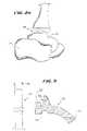
- FIG. 1is a view of the lower leg and foot skeleton.
- FIG. 2is a lateral view of a human foot and lower leg skeleton with the fibula shown in an assembly format and having a planarly resected tibia and talus.
- FIG. 2 ais a posterior view of a human foot and lower leg skeleton with the fibula not shown and planar cuts of the tibia and talus are depicted.
- FIG. 3shows an intramedullary guidance system for providing intramedullary alignment of the tibial and/or talar cuts, one end of the system being oriented toward the tibia and the other end oriented toward the talus.
- FIG. 4is a lateral view of a lower leg and foot demonstrating the intramedullary insertion of a guide pin through the superior part of the tibia and terminating in the talus.
- FIG. 5is a lateral view of a lower leg and foot demonstrating the intramedullary insertion of a guide pin through the plantar surface of the calcaneus, passing through the talus and terminating in the tibia at variable lengths.
- FIG. 5 ais a sectional view of a foot and depicts the insertion and removal of a guide pin through the plantar surface of the calcaneus, passing through the talus and terminating in the tibia, to produce an intramedullary channel, which may be made of various dimensions by using the guide pin to also direct the course of intramedullary reamers.
- FIG. 6is a lateral sectional view of the lower leg and foot showing the guide pin surrounded by the reaming instrument creating the intramedullary passage.
- FIG. 7is a lateral view and partial cross section of the human lower leg and foot showing the intramedullary channel and a resected portion of the anterior lower tibia to allow easier insertion of an intramedullary cutting guide.
- FIG. 8is a posterior section of the lower leg and foot with the fibula not shown and depicting the insertion of the intramedullary cutting guide between the tibia and the talus.
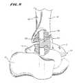
- FIG. 9is a perspective view of a talo-calcaneal reaming jig.
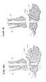
- FIG. 9 ais a lateral/partial sectional view depicting the insertion of the reaming tool in the talo-calcaneal reaming jig for the posteriorly directed inferior stem to help support the talar component (the drill hole and stem can be only in the talus or extend into the calcaneus for increased stability, and the anterior-posterior position of the talar support stem can be variable).
- FIG. 9 bis a cross-sectional view of the talo-calcaneal jig and channel as positioned on the talus.
- FIG. 9 cis a sectional view of resultant channel after the jig is removed, also showing the talar support stem.
- FIG. 10is a lateral cross-sectional view of the upper prosthetic body, showing the tibial stem and tibial component.
- FIG. 10 ais a side view of an alternative embodiment of an upper prosthetic body with a shorter tibial stem than shown in FIG. 10 .
- FIG. 11shows the insertion of a tibial stem through the calcaneus and talus, and (if needed) through an anti-rotational sleeve.
- FIG. 12is a perspective view of the optional anti-rotational sleeve for the tibial stem.
- FIG. 13is a lateral cross sectional view of the tibial stem in the lower tibia and fixed with screws and (optionally) with the anti-rotational sleeve.
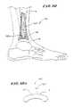
- FIG. 14shows a lateral cross sectional view of a lower prosthetic body in the foot, including the talar component with posterior fixation blade (if needed), talar fixation stem (extending into the calcaneus), and anterior talo-calcaneal fixation screws.
- FIG. 15shows both the upper and lower prosthetic bodies.
- FIG. 16shows an alternative lower prosthetic unit, with talar fixation stem at various angles.
- FIG. 17shows another alternative lower prosthetic unit, with talar fixation stem at various angles.
- the footcomprises fourteen phalanges or toe bones 11 connected to the metatarsus bones 13 .
- There are also seven tarsal bones 14of which the talus 15 supports the tibia 16 and the fibula 18 , and the heel bone or calcaneus 17 .
- the talus 15 and the calcaneus 17are the largest and are adjacent to each other.
- the other tarsal bonesinclude the navicular 19 , three cuneiforms 21 , and the cuboid 23 .
- FIG. 2 and FIG. 2 ashows (in FIG. 2 a , the tibia 16 and talus 15 have been resected with the removed portions shown in phantom lines, leaving two planar surfaces 25 ).
- a planar surfaceincreases the amount of bone available for the fixation of a selected prosthetic base. This provides greater stability and less stress absorption. This also decreases the probability of prosthesis loosening and subsidence.
- FIG. 3shows the components of an intramedullary guidance system 10 for providing a desired alignment of the tibia and talar before and while the tibial and/or talar cuts shown in FIG. 2 are made.
- the system 10includes an intramedullary guide pin 27 .
- the intramedullary guide pin 27is made, e.g., of an inert material used in the surgical arts, such as surgical steel.
- the guide pin 27may possess a range of desired diameters 29 , depending upon the function or functions it is intended to perform.
- the diameter 29may be relatively small, e.g., about 2 mm to 4 mm, if the pin 27 is to be used principally to form an intramedullary void, as will be described later.
- the diameter 29can be made larger, e.g., upwards to about 10 mm, if the pin 27 is to be used to guide passage of a surgical instrument, such as an intramedullary reamer or drill, to form an enlarged intramedullary void, as will also be described later.
- the guide pin 27may be introduced through the tibia (as FIG. 4 shows) or through the calcaneus (as FIG. 5 shows). Before the guide pin 27 is introduced, the foot and ankle are first aligned in an acceptable position. One skilled in the art will recognize that this may require surgically opening the ankle joint to loosen contractures (permanent contraction of muscles, ligaments, tendons) and scarring.
- a minimal exposure 200is made at the tibial tubercle with an awl. Once the exposure has been made, the exposure may be kept open under distraction, pulling of the skin, or any other method common in the surgical arts.
- Non invasive visualization of the procedurecan be accomplished through fluoroscopy or real time MRI, as well as through other means well known to those skilled in the art. Alternatively, or in conjunction with such less invasive means of visualization, open visualization may be used for part and/or all of the procedure.
- the guide pin 27passed through the tibia 16 , the tibial plafond, and enters the talus.
- the guide pin 27When introduced through the calcaneus (see FIG. 5 ), the guide pin 27 is placed retrograde through a minimal exposure in the calcaneus 17 .
- the exposuremay be kept open under any method common in the surgical arts and previously discussed.
- non invasive visualization of the calcaneus approachcan be accomplished through fluoroscopy or real time MRI, as well as through other means well known to those skilled in the art.
- open visualizationmay be used for part and/or all of the procedure.
- the guide pin 27passes through the calcaneus, through the talus 15 , through the tibial plafond, and into the tibial shaft.
- FIG. 5 ashows, upon removal, the guide pin 27 leaves behind an intramedullary guide void or passage 28 through the region where the tibia adjoins the talus.
- the passage 28is sized according to the diameter 29 of the guide pin 27 , or with a reamer to an appropriate size consistent with the size of the bones (the calcaneus, the talus, and the tibia).
- an anterior section S of the tibia 16can be removed by cutting, to expose the anterior portion of the ankle joint and the guide passage 28 .
- the system 10also includes an intramedullary cutting guide 31 , which is introduced into the ankle through an anterior surgical approach.
- the intradmedullary cutting guide 31functions to guide the saw blade used to create the planar surfaces 25 on the tibia and/or talus, as shown in FIG. 2 .
- the cutting guideincludes one or more cutting slots 33 , through which the saw blade passes.
- the cutting guide 31also includes an intramedullary locating feature, which in the illustrated embodiment takes the form of an intramedullary locating post 35 (see FIG. 3 ).
- the intramedullary cutting guide 31may be inserted anteriorly into the ankle joint after the resection of a small amount of bone from the anterior “lip” of the tibia.
- the alignment post 35fits into the intramedullary guide passage 28 in both the talus and tibia.
- the intramedullary post 35aligns the cutting guide 31 in the desired orientation with the talus 15 and tibia 16 .
- Intramedullary guidanceenables the surgeon to produce bony cuts that more closely approximate the mechanical axis of the leg, which extramedullary guides cannot do.
- the upper slot 33 of the cutting guide 31is aligned with the tibial shaft.
- the lower slot 33is aligned in the same direction into the dome of the talus.
- the intramedullary post 35maintains alignment as a bone saw is passed through the slots 33 , across the end regions of talus and tibia.
- the aligned planar surfaces 25are thereby formed with intramedullary guidance. Removal of the cutting guide 31 exposes these planar surfaces 25 , as FIG. 2 and FIG. 2 a show.
- intradmedullary guidancethe cuts are superior to cuts using extramedullary guidance.
- Extramedullary guidance systemsrely on surface bony prominences and visualization of the anterior ankle joint. These landmarks are inconsistent and can misdirect bony cuts by the surgeon.
- the intramedullary guidance system 10can be conveniently used with various surgical instruments or prosthetic parts. Because extramedullary alignment is avoided, more precise alignment can be made.
- the guide pin 27can serve an additional function, namely, to guide the passage of an intramedullary reaming device or a cannulated drill 30 .
- the guide pin 27is used to direct the reaming device 30 over it. A minimally larger exposure will be required on the bottom of the foot to allow the passage of the reaming device or drill bit over the guide pin 27 .
- the reaming device 30can be guided by the intramedullary guide pin 27 , either along a superior path, through the tibia and into the talus (as FIG. 4 shows), or along an inferior path, through the calcaneus and talus and into the tibia (as FIG. 5 shows). Guided by the pin 27 , the reaming device 30 leaves behind an enlarged intramedullary void or passage 28 .
- the guide pin 27 and reaming device 30may be placed through the tibia or calcaneus simultaneously, or a reaming rod may be placed through the tibia or calcaneus without a guide pin 27 , although it is preferable to use a guide pin.
- the reamer device 30is preferably 5, 6, 7, 8, 9, or 10 mm wide, depending on the size of the patient's tibia 16 .
- the alignment post 35 of the cutting guide 31is sized to fit into the enlarged reamed intramedullary passage 28 .
- the post 35aligns the cutting guide 31 in the desired orientation with the talus and tibia for forming the end cuts, as well maintain the alignment of the reamed intramedullary passage 28 .
- the size of the alignment post 35 of the cutting guide 31depends upon how the intramedulary channel is formed. For example, if just a guide pin is used to form the channel, the post 35 will be sized smaller than If an intramedullary reamer is used in forming the channel. If just the guide pin is used to form the channel, straightforward, minimally invasive percutaneous access can be used to insert the guide pin into the calcaneus, into the talus and tibia, thereby forming the relatively small diameter intradmedullary channel.
- An upper prosthesis bodymay be fixed directly to planar cut of the tibia with or without a tibial stem.
- a lower prosthesis body of the talusmay likewise be fixed directly to the planar cut of the talus, or with a fixation stem into the talus or into both the talus and the calcaneus.
- the upper and lower prosthesis bodiesmay be used in combination or singly.
- stemmed upper or lower prosthesesmay be located on the planar cuts, either individually or in combination.
- the reamed intramedullary passage 28 formed in the tibia using the intramedullary guidance system 10can, e.g., serve to accept a stemmed upper prosthetic body 170 , as FIG. 10 shows.
- the stemmed upper prosthetic bodycan take various forms. Certain representative embodiments are found in U.S. patent application Ser. No. 09/694,100, now U.S. Pat. No. 6,663,669, filed Oct. 20, 2000, entitled “Ankle Replacement System,” which is incorporated herein by reference.
- the upper prosthetic body 170comprises an elongated tibial stem 150 .
- the tibial stem 150may be made of any total joint material or materials commonly used in the prosthetic arts, including, but not limited to, metals, ceramics, titanium, titanium alloys, tantalum, chrome cobalt, surgical steel, or any other total joint replacement metal and/or ceramic, bony in-growth surface, sintered glass, artificial bone, any uncemented metal or ceramic surface, or a combination thereof.
- the tibial stem 150may further be covered with one or more coatings such as antimicrobial, antithrombotic, and osteoinductive agents, or a combination thereof. These agents may further be carried in a biodegradable carrier material with which the pores of tibial stem 150 may be impregnated. See U.S. Pat. No. 5,947,893.
- the tibial stem 150may be variable lengths, e.g., from 2 cm to 30 cm and variable widths, e.g., from 6 to 12 mm. In the preferred embodiment, the tibial stem 150 is preferably approximately 6 inches in length. Of course, it should be understood that the disclosed tibial stem could be of virtually any length, depending upon the size of the patient, his or her bone dimensions, and the anticipated future mobility of the patient.
- the upper prosthetic body 170 ′can comprises a shorter tibial stem 150 ′ having a diameter generally the same size (or slightly larger) than the guide pin that forms the passage 28 .
- the body 170 ′can also include several short, spaced apart derotation pegs 171 .
- the tibial stem 150may be inserted into the reamed intramedullary passage 28 either superiorly (through the tibia), or inferiorly (through the calcaneus and talus and into the tibia), depending upon the path along which the guide pin 27 and reaming device 30 have followed.
- the tibial stem 150when the passage 28 is made by the pin 27 and reaming device 30 superiorly though the tibia, the tibial stem 150 is inserted in a superior path through the tibia.
- the tibial stem 150when the passage 28 is made by the pin 27 and reaming device 30 retrograde through the calcaneus, the tibial stem 150 may be introduced inferiorly through the retrograde passage 28 through the calcaneus and talus into the tibia ( FIG. 11 ).
- the stem 150is fixed in the lower tibia ( FIG. 13 ).
- the tibial stem 150may be fixed in the tibia 16 with poly(methylmethacrylate) bone cement, hydroxyapatite, a ground bone composition, screws, or a combination thereof, or any other fixation materials common to one of skill in the art of prosthetic surgery.
- An anti-rotational sleeve 406(see FIG. 12 ) can also be used alone or in combination with other fixation devices.
- the tibial stem 150is fixed to the tibia 16 with screws 125 a and 125 b . If screws are used, they can extend anteriorly, posteriorly, medially, laterally and/or at oblique angles, or any combination thereof.
- a sleeve 406may be placed about the stem 150 , e.g., as the stem is passed between the talus and tibia.
- the sleeve 406engages bone along the passage 28 .
- the sleeve 406imparts an anti-rotational feature, including, e.g., outwardly extending fins.
- the sleeve 406may be used in combination with the screws or alone without the screws.
- the distal end of the tibial stem 150may additionally have interlocking components, common to those of skill in the art, at its lower surface to allow other components of the upper prosthesis body to lock into the tibial stem.
- the tibial stem 150has a Morse Taper 115 b at its lower surface to which a concave dome 155 is attached.
- the dome 155can be made of a plastic, ceramic, or metal.
- the dome 115articulates with the lower ankle joint surface, which can be the talus bone itself or a lower prosthetic body fixed to the talus, as will now be described.
- a lower prosthetic bodycan be supported on the talus, either alone or in association with an upper prosthetic body mounted in the tibia.
- the upper prosethetic bodymay be stemmed, as just described, or affixed directly to the tibia without use of a stem.
- the lower prosthetic bodymay be stemmed or affixed directed to the talus.
- the stem for the talar componentdoes not extend beyond the inferior surface of the talar.
- a subtalar jointi.e., the joint formed between talus and calcaneus
- the subtalar jointmay be fused using any method common to those of skill in the surgical arts including, but not limited to, fusion with, for example, poly (methylmethacrylate) bone cement, hydroxyapatite, ground bone and marrow composition, plates, and screws, or a combination thereof.
- FIG. 14shows one method of fusing the talus 15 to the calcaneus 17 using a stem 110 , a plate 130 , and screws 133 a , 133 b .
- the talo-calcaneal stem 110is shown with a Morse Taper 115 a protruding from the stem 110 and extending beyond the proximal (top) surface of the talus 15 .
- the Morse Tapercould extend down from the talar component into the stem.
- FIG. 14also shows an arrangement in which the lower end of the tibia has not been cut and does not carry a prosthesis.
- the talo-calcaneal stem 110may be made of various materials commonly used in the prosthetic arts including, but not limited to, titanium, titanium alloys, tantalum, chrome cobalt, surgical steel, or any other total joint replacement metal and/or ceramic, bony in-growth surface, sintered glass, artificial bone, any uncemented metal or ceramic surface, or a combination thereof.
- the talo-calcaneal stem 110may further be covered with various coatings such as antimicrobial, antithrombotic, and osteoinductive agents, or a combination thereof. These agents may further be carried in a biodegradable carrier material with which the pores of the surface of the talo-calcaneal stem 110 may be impregnated. See U.S. Pat. No.
- the talo-calcaneal stemmay be coated and/or formed from a material allowing bony in-growth, such as a porous mesh, hydroxyapetite, or other porous surface.
- the talo-calcaneal stem 110may be any size or shape deemed appropriate to fuse the subtalar joint of a patient and is desirably selected by the physician taking into account the morphology and geometry of the site to be treated.
- the stem 110may be of variable lengths, from 2 cm to 12 cm, and variable widths, from 4 to 14 mm.
- the talo-calcaneal stem 110is approximately 65 to 75 mm in length and approximately 7 to 10 mm wide. While in the disclosed embodiment the stem 110 has a circular cross-section, it should be understood that the stem could formed in various other cross-sectional geometries, including, but not limited to, elliptical, polygonal, irregular, or some combination thereof.
- the stemcould be arced to reduce and/or prevent rotation, and could be of constant or varying cross-sectional widths.
- the physicianis desirably able to select the desired size and/or shape based upon prior analysis of the morphology of the target bone(s) using, for example, plain film x-ray, fluoroscopic x-ray, or MRI or CT scanning.
- the size and/or shapeis selected to optimize support and/or bonding of the stem to the surrounding bone(s).
- the talo-calcaneal stem 110can be passed from the top of the talus 15 into the distal calcaneus 17 through a cavity 601 that is drilled through the talus 15 and calcaneus 17 .
- the cavity 601is preferably drilled after the surface of the talus 15 has cut and flattened, and after the location of the upper prosthesis body.
- a suitable jig 600may be placed in the joint to assist with locating and placing the cavity 601 .
- Certain representative embodimentsare found in U.S. patent application Ser. No. 09/694,100, now U.S. Pat. No. 6,663,669, filed Oct. 20, 2000, entitled “Ankle Replacement System,” which is incorporated herein by reference.
- the jig 600includes a drill guide 620 and a post 610 that, in use, rests in the intramedullary passage 28 (see FIGS. 9 a and 9 b ).
- the drill guide 620can extend from posterior to anterior (as FIG. 9 shows), or alternatively, from anterior to posterior.
- the drill bit 603 for the jig 600(see FIG. 9 a ) is preferably about 1 ⁇ 2 mm wider than the width of the talo-calcaneal stem 110 .
- the talo-calcaneal stem 110may be further adapted so that the talo-calcaneal stem 110 is inserted as the cavity is being drilled or so that the talo-calcaneal stem itself is used to drill the hole.
- any easily accessed cartilage from the talo-calcaneal jointmay be scraped, e.g., using a small angled curet or any other instrument commonly used in the surgical arts.
- the subtalar jointcan then be fused by passing a talo-calcaneal stem 110 down the cavity 601 .
- the cavity 601may be partially filled with a bone cement prior to the installation of the talo-calcaneal stem 110 to help fix the talo-calcaneal stem 110 to the subtalar joint.
- the stem 110incorporates screw holes or other openings to accommodate interlocking hardware, such as screws, to increase fixation and minimize rotation.
- the stem 110desirably includes a Morse Taper 115 a .
- a cap 160 afits on the Morse Taper 115 a to form an articulating joint surface with the upper prosthesis.
- the upper surface of the cap 160can be designed to fit the particular needs and walking requirements anticipated by the physician and patient.
- a low demand surfacesuch as for an individual of advanced years having a less-active lifestyle, could comprise a simple smooth arc, without the “peaks and valleys” of the talus 15 that run from anterior to posterior.
- a low demand surfacemay not require a difference in the anterior to posterior talar width, which in an adult male can be approximately 4 to 5 mm wider in its anterior portion than its posterior portion.
- a higher demand surface, for a more active individualmay incorporate the trochlea (valley) in the talus as well as various other anatomical features found on the talus.
- the stem 110 aextends downward from the cap 160 a , forming an angle ⁇ relative to the vertical axis—taken relative to the longitudinal axis of cap 160 a (front to rear of the foot).
- the angle ⁇will range from 105° to 205°, depending upon the size and orientation of the calcaneus 17 as well as the position of the lower prosthesis body.
- the stemmay form an angle ⁇ relative to the vertical axis—taken relative to the transverse axis of the cap 160 b (medial to lateral side of the foot).
- the angle ⁇will range from 155° (on the medial side of the foot) to 240° (on the lateral side of the foot), depending upon the size and orientation of the calcaneus 17 as well as the position of the lower prosthesis body. Desirably, the lower portion of the stem of the implant will not extend outside of the calcaneus.
- a plate 130may be fixed to the top of the talus 15 .
- the plate 130can have an overhang portion 131 which allows the plate 130 to overlap both the talus 15 and part of the calcaneus 17 .
- the plate 130 and overhang portion 131may be made of various materials commonly used in the prosthetic arts including, but not limited to, polyethylene, biologic type polymers, hydroxyapetite, rubber, titanium, titanium alloys, tantalum, chrome cobalt, surgical steel, or any other total joint replacement metal and/or ceramic, bony in-growth surface, sintered glass, artificial bone, any porous metal coat, metal meshes and trabeculations, metal screens, uncemented metal or ceramic surface, other bio-compatible materials, or any combination thereof.
- the plate 130 and overhang portion 131may further be covered with various coatings such as antimicrobial, antithrombogenic, and osteoinductive agents, or a combination thereof. See U.S. Pat. No. 5,866,113 to Hendriks, et al, incorporated herein by reference. These agents may further be carried in a biodegradable carrier material with which the pores of the plate 130 and overhang portion 131 may be impregnated.
- the traycomprises a metal-backed polyethylene component.
- the plate 130 and/or the overhang portion 131may be fixed to the subtalar joint 90 with poly(methylmethacrylate) bone cement, hydroxyapatite, a ground bone and marrow composition, screws, or a combination thereof, or any other fixation materials common to one of skill in the art of joint replacement surgery.
- the plate 130 and overhang portion 131are fitted over the Morse Taper 115 a of the talo-calcaneal stem 110 and fixed to the talus 15 and calcaneus 17 with screws 133 a and 133 b .
- the posterior overhang portion 131can be eliminated.
- the lower prosthesis bodymay be formed in a single unit or, as illustrated, as a multi-component prosthesis.
- the upper prosthesis bodymay additionally comprise a fibular prosthesis of any variety known in the art of joint replacement.
- the fibular prosthesiswould replace the inferior end of the fibula, especially when this prosthesis is used to revise a total ankle replacement system that has removed the distal end of the fibula.
- either the lower prosthesis body, upper prosthesis body, or both, as described abovemay be fixed into strengthened or fortified bone.
- the bones of the subtalar joint, tibia, or fibulamay be strengthened prior to or during fixation of the prosthesis using the methods described in U.S. Pat. No. 5,827,289 to Reiley. This type of bone strengthening procedure is particularly suggested for osteoporotic patients who wish to have a total ankle replacement.
- installed prosthetic systemneed not include a calcaneal stem.
- the systemwould only include the tibial stem, the tibial component and the talar component.
- the installed prosthetic systemneed not include a tibial stem component.
- the systemwould include the tibial component without the Morse Taper attachments on its superior surface, the talar component, and the calcaneal stem component.
- the installed prosthetic systemneed not include any stemmed component being utilized.
- the intramedullary guidance system 10deployed either superiorly from the tibia, or inferiorly from the calcaneus, would still provide intramedullary alignment of the tibial and talar cuts.
- the tibial component and the talar componentwould be utilized, without Morse Taper stems or holes on either implant, but the intramedullary guidance system would still be used to insure properly aligned cuts in the talus and tibia.
- the devices and methods of the present inventioncould be used as an index (initial) total ankle replacement, as well as a revision ankle replacement. If used as a revision device, only a portion of the disclosed methods and devices may be necessary in conjunction with such a procedure.
Landscapes
- Health & Medical Sciences (AREA)
- Life Sciences & Earth Sciences (AREA)
- Surgery (AREA)
- Orthopedic Medicine & Surgery (AREA)
- Animal Behavior & Ethology (AREA)
- Veterinary Medicine (AREA)
- Public Health (AREA)
- Engineering & Computer Science (AREA)
- Biomedical Technology (AREA)
- Heart & Thoracic Surgery (AREA)
- General Health & Medical Sciences (AREA)
- Molecular Biology (AREA)
- Medical Informatics (AREA)
- Nuclear Medicine, Radiotherapy & Molecular Imaging (AREA)
- Oral & Maxillofacial Surgery (AREA)
- Dentistry (AREA)
- Neurology (AREA)
- Cardiology (AREA)
- Transplantation (AREA)
- Vascular Medicine (AREA)
- Prostheses (AREA)
- Surgical Instruments (AREA)
Abstract
Description
Claims (5)
Priority Applications (1)
| Application Number | Priority Date | Filing Date | Title |
|---|---|---|---|
| US11/981,026US7717920B2 (en) | 1999-10-22 | 2007-10-31 | Ankle replacement prostheses |
Applications Claiming Priority (7)
| Application Number | Priority Date | Filing Date | Title |
|---|---|---|---|
| US16089299P | 1999-10-22 | 1999-10-22 | |
| US09/694,100US6663669B1 (en) | 1999-10-22 | 2000-10-20 | Ankle replacement system |
| US09/935,479US6673116B2 (en) | 1999-10-22 | 2001-08-23 | Intramedullary guidance systems and methods for installing ankle replacement prostheses |
| US10/699,999US6875236B2 (en) | 1999-10-22 | 2003-11-03 | Intramedullary guidance systems and methods for installing ankle replacement prostheses |
| US11/038,803US7314488B2 (en) | 1999-10-22 | 2005-01-19 | Intramedullary guidance systems and methods for installing ankle replacement prostheses |
| US11/895,721US7641697B2 (en) | 1999-10-22 | 2007-08-27 | Systems and methods for installing ankle replacement prostheses |
| US11/981,026US7717920B2 (en) | 1999-10-22 | 2007-10-31 | Ankle replacement prostheses |
Related Parent Applications (1)
| Application Number | Title | Priority Date | Filing Date |
|---|---|---|---|
| US11/895,721DivisionUS7641697B2 (en) | 1999-10-22 | 2007-08-27 | Systems and methods for installing ankle replacement prostheses |
Publications (2)
| Publication Number | Publication Date |
|---|---|
| US20080065227A1 US20080065227A1 (en) | 2008-03-13 |
| US7717920B2true US7717920B2 (en) | 2010-05-18 |
Family
ID=25467208
Family Applications (6)
| Application Number | Title | Priority Date | Filing Date |
|---|---|---|---|
| US09/935,479Expired - LifetimeUS6673116B2 (en) | 1999-10-22 | 2001-08-23 | Intramedullary guidance systems and methods for installing ankle replacement prostheses |
| US10/699,999Expired - LifetimeUS6875236B2 (en) | 1999-10-22 | 2003-11-03 | Intramedullary guidance systems and methods for installing ankle replacement prostheses |
| US11/038,803Expired - LifetimeUS7314488B2 (en) | 1999-10-22 | 2005-01-19 | Intramedullary guidance systems and methods for installing ankle replacement prostheses |
| US11/648,042Expired - LifetimeUS8034114B2 (en) | 1999-10-22 | 2006-12-29 | Systems and methods for installing ankle replacement prostheses |
| US11/895,721Expired - LifetimeUS7641697B2 (en) | 1999-10-22 | 2007-08-27 | Systems and methods for installing ankle replacement prostheses |
| US11/981,026Expired - Fee RelatedUS7717920B2 (en) | 1999-10-22 | 2007-10-31 | Ankle replacement prostheses |
Family Applications Before (5)
| Application Number | Title | Priority Date | Filing Date |
|---|---|---|---|
| US09/935,479Expired - LifetimeUS6673116B2 (en) | 1999-10-22 | 2001-08-23 | Intramedullary guidance systems and methods for installing ankle replacement prostheses |
| US10/699,999Expired - LifetimeUS6875236B2 (en) | 1999-10-22 | 2003-11-03 | Intramedullary guidance systems and methods for installing ankle replacement prostheses |
| US11/038,803Expired - LifetimeUS7314488B2 (en) | 1999-10-22 | 2005-01-19 | Intramedullary guidance systems and methods for installing ankle replacement prostheses |
| US11/648,042Expired - LifetimeUS8034114B2 (en) | 1999-10-22 | 2006-12-29 | Systems and methods for installing ankle replacement prostheses |
| US11/895,721Expired - LifetimeUS7641697B2 (en) | 1999-10-22 | 2007-08-27 | Systems and methods for installing ankle replacement prostheses |
Country Status (5)
| Country | Link |
|---|---|
| US (6) | US6673116B2 (en) |
| EP (1) | EP1435883B1 (en) |
| JP (1) | JP2005500115A (en) |
| AU (1) | AU2002331634B2 (en) |
| WO (1) | WO2003017822A2 (en) |
Cited By (26)
| Publication number | Priority date | Publication date | Assignee | Title |
|---|---|---|---|---|
| US20120245701A1 (en)* | 2011-03-24 | 2012-09-27 | Rudolf Zak | Hemi Ankle Implant |
| US8668743B2 (en) | 2010-11-02 | 2014-03-11 | Adam D. Perler | Prosthetic device with multi-axis dual bearing assembly and methods for resection |
| US9186154B2 (en) | 2011-03-17 | 2015-11-17 | Zimmer, Inc. | Patient-specific instruments for total ankle arthroplasty |
| US9610168B2 (en) | 2014-05-12 | 2017-04-04 | Integra Lifesciences Corporation | Total ankle replacement prosthesis |
| US9907561B2 (en) | 2012-12-27 | 2018-03-06 | Wright Medical Technologies, Inc. | Ankle replacement system and method |
| US9918724B2 (en) | 2012-12-27 | 2018-03-20 | Wright Medical Technology, Inc. | Ankle replacement system and method |
| US9974588B2 (en) | 2012-12-27 | 2018-05-22 | Wright Medical Technology, Inc. | Ankle replacement system and method |
| US10321922B2 (en) | 2012-12-27 | 2019-06-18 | Wright Medical Technology, Inc. | Ankle replacement system and method |
| US10517737B2 (en) | 2015-05-22 | 2019-12-31 | Stryker European Operations Limited | Joint or segmental bone implant for deformity correction |
| US10610368B2 (en) | 2018-05-26 | 2020-04-07 | Acumed Llc | Ankle fusion system with expandable spacer |
| US11000296B2 (en) | 2017-12-20 | 2021-05-11 | Encore Medical, L.P. | Joint instrumentation and associated methods of use |
| US11013607B2 (en) | 2017-09-22 | 2021-05-25 | Encore Medical, L.P. | Talar ankle implant |
| US11116524B2 (en) | 2012-12-27 | 2021-09-14 | Wright Medical Technology, Inc. | Ankle replacement system and method |
| US11253275B2 (en)* | 2017-01-16 | 2022-02-22 | Fournitures Hospitalieres Industrie | Surgical apparatus for cutting a tibia of a patient for the implantation of an ankle prosthesis |
| US11311302B2 (en) | 2012-12-27 | 2022-04-26 | Wright Medical Technology, Inc. | Ankle replacement system and method |
| US20220175554A1 (en)* | 2011-11-04 | 2022-06-09 | Smith & Nephew, Inc. | Surgical Instrumentation Assembly for Positioning an Ankle Prosthesis |
| US11857207B2 (en) | 2016-03-23 | 2024-01-02 | Wright Medical Technology, Inc. | Circular fixator system and method |
| US11872137B2 (en) | 2021-06-15 | 2024-01-16 | Wright Medical Technology, Inc. | Unicompartmental ankle prosthesis |
| US12114872B2 (en) | 2021-03-30 | 2024-10-15 | Wright Medical Technology, Inc. | Alignment guide, systems, and methods |
| US12196856B2 (en) | 2021-06-09 | 2025-01-14 | Wright Medical Technology | Alignment systems and methods |
| US12201538B2 (en) | 2021-09-21 | 2025-01-21 | Wright Medical Technology, Inc. | Expanding tibial stem |
| US12239539B2 (en) | 2021-06-07 | 2025-03-04 | Wright Medical Technology, Inc. | Joint replacement prosthesis with trans-cortical stems |
| US12350160B2 (en) | 2021-06-08 | 2025-07-08 | Wright Medical Technology, Inc. | Modular implant with external fixation |
| US12396755B2 (en) | 2022-01-28 | 2025-08-26 | Wright Medical Technology, Inc. | Methods and apparatus for joint repair |
| US12396737B2 (en) | 2020-04-16 | 2025-08-26 | Wright Medical Technology, Inc. | Chamfer guidance systems and methods |
| US12433532B2 (en) | 2022-06-02 | 2025-10-07 | Wright Medical Technology, Inc. | Flexion/extension surgical guides and methods of using the same |
Families Citing this family (139)
| Publication number | Priority date | Publication date | Assignee | Title |
|---|---|---|---|---|
| US7534263B2 (en) | 2001-05-25 | 2009-05-19 | Conformis, Inc. | Surgical tools facilitating increased accuracy, speed and simplicity in performing joint arthroplasty |
| US7468075B2 (en)* | 2001-05-25 | 2008-12-23 | Conformis, Inc. | Methods and compositions for articular repair |
| US8083745B2 (en) | 2001-05-25 | 2011-12-27 | Conformis, Inc. | Surgical tools for arthroplasty |
| US20030055502A1 (en)* | 2001-05-25 | 2003-03-20 | Philipp Lang | Methods and compositions for articular resurfacing |
| US9289153B2 (en)* | 1998-09-14 | 2016-03-22 | The Board Of Trustees Of The Leland Stanford Junior University | Joint and cartilage diagnosis, assessment and modeling |
| WO2000035346A2 (en) | 1998-09-14 | 2000-06-22 | Stanford University | Assessing the condition of a joint and preventing damage |
| DE60025532T2 (en)* | 1999-10-22 | 2006-09-14 | Reiley, Mark A., Peidmont | ANKLE PROSTHESIS |
| US8496712B2 (en) | 1999-10-22 | 2013-07-30 | Inbone Technologies, Inc. | Systems and methods for installing ankle replacement prostheses |
| US6673116B2 (en)* | 1999-10-22 | 2004-01-06 | Mark A. Reiley | Intramedullary guidance systems and methods for installing ankle replacement prostheses |
| WO2002053105A2 (en)* | 2001-01-02 | 2002-07-11 | Advanced Ceramics Research, Inc. | Compositions and methods for biomedical applications |
| US8439926B2 (en) | 2001-05-25 | 2013-05-14 | Conformis, Inc. | Patient selectable joint arthroplasty devices and surgical tools |
| US7935118B2 (en)* | 2002-06-21 | 2011-05-03 | Depuy Products, Inc. | Prosthesis removal cutting guide, cutting tool and method |
| US20030236522A1 (en) | 2002-06-21 | 2003-12-25 | Jack Long | Prosthesis cavity cutting guide, cutting tool and method |
| WO2004014243A1 (en) | 2002-08-10 | 2004-02-19 | William H Simon | Method and apparatus for repairing the mid-food region via an intermedullary nail |
| US7452381B2 (en)* | 2003-01-30 | 2008-11-18 | Mayo Foundation For Medical Education And Research | Radial head replacement system |
| US20070027547A1 (en)* | 2003-06-27 | 2007-02-01 | Advanced Bio Surfaces, Inc. | System and method for ankle arthroplasty |
| KR20100086066A (en) | 2003-08-27 | 2010-07-29 | 링크 아메리카, 인코포레이티드 | Ankle-joint endoprosthesis |
| US7524103B2 (en)* | 2003-11-18 | 2009-04-28 | Boston Scientific Scimed, Inc. | Apparatus for mixing and dispensing a multi-component bone cement |
| CA2548469A1 (en)* | 2003-12-01 | 2005-06-16 | Smith & Nephew, Inc. | Humeral nail with insert for fixing a screw |
| US20050288792A1 (en)* | 2004-06-23 | 2005-12-29 | Landes Mark D | Modular ankle prosthesis and associated method |
| US9949843B2 (en) | 2004-08-09 | 2018-04-24 | Si-Bone Inc. | Apparatus, systems, and methods for the fixation or fusion of bone |
| US20070156241A1 (en) | 2004-08-09 | 2007-07-05 | Reiley Mark A | Systems and methods for the fixation or fusion of bone |
| US9662158B2 (en) | 2004-08-09 | 2017-05-30 | Si-Bone Inc. | Systems and methods for the fixation or fusion of bone at or near a sacroiliac joint |
| US20060036251A1 (en) | 2004-08-09 | 2006-02-16 | Reiley Mark A | Systems and methods for the fixation or fusion of bone |
| US20180228621A1 (en) | 2004-08-09 | 2018-08-16 | Mark A. Reiley | Apparatus, systems, and methods for the fixation or fusion of bone |
| US8388667B2 (en) | 2004-08-09 | 2013-03-05 | Si-Bone, Inc. | Systems and methods for the fixation or fusion of bone using compressive implants |
| US20080319445A9 (en)* | 2004-08-17 | 2008-12-25 | Scimed Life Systems, Inc. | Apparatus and methods for delivering compounds into vertebrae for vertebroplasty |
| US8038682B2 (en)* | 2004-08-17 | 2011-10-18 | Boston Scientific Scimed, Inc. | Apparatus and methods for delivering compounds into vertebrae for vertebroplasty |
| US20060091596A1 (en)* | 2004-11-03 | 2006-05-04 | Frank Marusiak | Auto-advance bar clamp |
| US7410488B2 (en) | 2005-02-18 | 2008-08-12 | Smith & Nephew, Inc. | Hindfoot nail |
| US9452001B2 (en)* | 2005-02-22 | 2016-09-27 | Tecres S.P.A. | Disposable device for treatment of infections of human limbs |
| JP4852596B2 (en)* | 2005-03-14 | 2012-01-11 | インボーン テクノロジーズ, インコーポレイテッド | Ankle replacement prosthesis |
| US8002841B2 (en)* | 2006-01-20 | 2011-08-23 | Synthes Usa, Llc | Method of preparing an ankle joint for replacement, joint prosthesis, and cutting alignment apparatus for use in performing an arthroplasty procedure |
| FR2896404B1 (en)* | 2006-01-24 | 2008-02-29 | Tornier Sas | SURGICAL INSTRUMENTATION ASSEMBLY FOR POSTING AN ANKLE PROSTHESIS |
| CN105030296A (en)* | 2006-02-06 | 2015-11-11 | 康复米斯公司 | Patient selectable joint arthroplasty devices and surgical tools |
| US8623026B2 (en) | 2006-02-06 | 2014-01-07 | Conformis, Inc. | Patient selectable joint arthroplasty devices and surgical tools incorporating anatomical relief |
| PL1859750T3 (en)* | 2006-05-24 | 2010-01-29 | Lopez Oliva Munoz Felipe | Locking nail system for arthrodesis reconstruction in calcaneus fractures |
| US8102863B1 (en)* | 2006-06-27 | 2012-01-24 | Qurio Holdings, Inc. | High-speed WAN to wireless LAN gateway |
| FR2906999B1 (en) | 2006-10-13 | 2009-06-05 | Tornier Sas | PROTHETIC SET OF ANKLE |
| GB2477662B (en)* | 2006-12-23 | 2011-12-07 | Corin Ltd | Improvements in and relating to an ankle prosthesis |
| WO2008157412A2 (en)* | 2007-06-13 | 2008-12-24 | Conformis, Inc. | Surgical cutting guide |
| US10398561B2 (en) | 2007-09-26 | 2019-09-03 | DePuy Synthes Products, Inc. | Talar implant system and method |
| WO2009044395A2 (en)* | 2007-10-01 | 2009-04-09 | Medilock Medical Solutions Ltd. | Orthopedic fastening device and kit for using the same |
| US20090105767A1 (en)* | 2007-10-18 | 2009-04-23 | Inbone Technologies, Inc. | Total joint subsidence protector |
| CN101917915B (en)* | 2007-11-26 | 2014-08-06 | 比德尔曼技术有限责任两合公司 | Nails and Osseosynthesis Kits for Heels |
| US8043375B2 (en)* | 2008-03-06 | 2011-10-25 | MoiRai Orthopaedic, LLC | Cartilage implants |
| US8668694B2 (en)* | 2008-06-06 | 2014-03-11 | Steven M. Teeny | Bone fixation assemblies and methods of use |
| US8313487B2 (en)* | 2008-06-24 | 2012-11-20 | Extremity Medical Llc | Fixation system, an intramedullary fixation assembly and method of use |
| US8343199B2 (en)* | 2008-06-24 | 2013-01-01 | Extremity Medical, Llc | Intramedullary fixation screw, a fixation system, and method of fixation of the subtalar joint |
| US20110230884A1 (en)* | 2008-06-24 | 2011-09-22 | Adam Mantzaris | Hybrid intramedullary fixation assembly and method of use |
| US8328806B2 (en) | 2008-06-24 | 2012-12-11 | Extremity Medical, Llc | Fixation system, an intramedullary fixation assembly and method of use |
| US8303589B2 (en) | 2008-06-24 | 2012-11-06 | Extremity Medical Llc | Fixation system, an intramedullary fixation assembly and method of use |
| US9044282B2 (en) | 2008-06-24 | 2015-06-02 | Extremity Medical Llc | Intraosseous intramedullary fixation assembly and method of use |
| US9289220B2 (en) | 2008-06-24 | 2016-03-22 | Extremity Medical Llc | Intramedullary fixation assembly and method of use |
| US9017329B2 (en)* | 2008-06-24 | 2015-04-28 | Extremity Medical, Llc | Intramedullary fixation assembly and method of use |
| EP2337510B1 (en) | 2008-06-25 | 2018-10-31 | Stryker European Holdings I, LLC | Surgical instrumentation for implanting a prothesis |
| US8012217B2 (en)* | 2008-07-03 | 2011-09-06 | Fellowship of Orthopaedic Researchers, LLC | Talar implants and methods of use |
| EP2339976B1 (en)* | 2008-07-09 | 2016-03-16 | Icon Orthopaedic Concepts, LLC | Ankle arthrodesis nail and outrigger assembly |
| US8414584B2 (en) | 2008-07-09 | 2013-04-09 | Icon Orthopaedic Concepts, Llc | Ankle arthrodesis nail and outrigger assembly |
| WO2010054363A1 (en)* | 2008-11-10 | 2010-05-14 | Temple University - Of The Commonwealth System Of Higher Education | Locking rod fusion device |
| US8808297B2 (en) | 2009-02-24 | 2014-08-19 | Microport Orthopedics Holdings Inc. | Orthopedic surgical guide |
| US8808303B2 (en)* | 2009-02-24 | 2014-08-19 | Microport Orthopedics Holdings Inc. | Orthopedic surgical guide |
| US8337503B2 (en)* | 2009-04-13 | 2012-12-25 | George John Lian | Custom radiographically designed cutting guides and instruments for use in total ankle replacement surgery |
| SG10201401326SA (en) | 2009-04-16 | 2014-10-30 | Conformis Inc | Patient-specific joint arthroplasty devices for ligament repair |
| CH701107B1 (en) | 2009-05-18 | 2013-11-29 | Biedermann Technologies Gmbh | Apparatus for drilling an arcuate bore. |
| US9011503B2 (en)* | 2009-07-14 | 2015-04-21 | Neil Duggal | Joint arthrodesis and arthroplasty |
| AU2010286660B2 (en) | 2009-08-25 | 2015-07-16 | Fellowship Of Orthopaedic Researchers, Inc. | Trochlear implants and methods of use |
| JP5999745B2 (en)* | 2009-12-04 | 2016-09-28 | 帝人ナカシマメディカル株式会社 | Artificial ankle |
| US9333090B2 (en) | 2010-01-13 | 2016-05-10 | Jcbd, Llc | Systems for and methods of fusing a sacroiliac joint |
| CA3002234C (en) | 2010-01-13 | 2020-07-28 | Jcbd, Llc | Sacroiliac joint fixation fusion system |
| US9381045B2 (en) | 2010-01-13 | 2016-07-05 | Jcbd, Llc | Sacroiliac joint implant and sacroiliac joint instrument for fusing a sacroiliac joint |
| US9421109B2 (en) | 2010-01-13 | 2016-08-23 | Jcbd, Llc | Systems and methods of fusing a sacroiliac joint |
| WO2014015309A1 (en) | 2012-07-20 | 2014-01-23 | Jcbd, Llc | Orthopedic anchoring system and methods |
| US8647391B2 (en) | 2010-07-07 | 2014-02-11 | Global Orthopaedic Solutions Llc | Malleolar replacement devices |
| US8690956B2 (en) | 2010-08-23 | 2014-04-08 | Fellowship Of Orthopaedic Researchers, Inc. | Talar implants and methods of use |
| US8647388B2 (en)* | 2010-08-27 | 2014-02-11 | Bluefish Orthopedics, Llc | Elbow prosthesis and method for use |
| EP2452641A1 (en)* | 2010-11-12 | 2012-05-16 | Kyon AG | Patellar ligament spacer for ACL injuries |
| EP2720628B1 (en) | 2011-06-17 | 2021-08-11 | Jcbd, Llc | Sacroiliac joint implant system |
| US9839462B2 (en)* | 2012-02-06 | 2017-12-12 | Arthrex, Inc. | Surgical cutting block |
| US9044321B2 (en) | 2012-03-09 | 2015-06-02 | Si-Bone Inc. | Integrated implant |
| US10363140B2 (en) | 2012-03-09 | 2019-07-30 | Si-Bone Inc. | Systems, device, and methods for joint fusion |
| EP2649966A1 (en) | 2012-04-12 | 2013-10-16 | Arthrex, Inc. | Talus surface implant |
| US9486226B2 (en) | 2012-04-18 | 2016-11-08 | Conformis, Inc. | Tibial guides, tools, and techniques for resecting the tibial plateau |
| EP3818947B1 (en) | 2012-05-04 | 2023-08-30 | SI-Bone, Inc. | Fenestrated implant |
| US9675471B2 (en) | 2012-06-11 | 2017-06-13 | Conformis, Inc. | Devices, techniques and methods for assessing joint spacing, balancing soft tissues and obtaining desired kinematics for joint implant components |
| DE202012103384U1 (en) | 2012-09-05 | 2012-09-24 | Signus Medizintechnik Gmbh | Pelvic ring implant |
| US9949839B2 (en) | 2013-03-13 | 2018-04-24 | Wright Medical Technology, Inc. | Revision implant augments, systems, and methods |
| BR112015018616A2 (en)* | 2013-03-14 | 2017-07-18 | Wright Medical Tech Inc | intramedullary technique and system for the ankle |
| WO2014146018A1 (en) | 2013-03-15 | 2014-09-18 | Jcbd, Llc | Systems and methods for fusing a sacroiliac joint and anchoring an orthopedic appliance |
| US9700356B2 (en) | 2013-07-30 | 2017-07-11 | Jcbd, Llc | Systems for and methods of fusing a sacroiliac joint |
| US9826986B2 (en) | 2013-07-30 | 2017-11-28 | Jcbd, Llc | Systems for and methods of preparing a sacroiliac joint for fusion |
| WO2014145902A1 (en) | 2013-03-15 | 2014-09-18 | Si-Bone Inc. | Implants for spinal fixation or fusion |
| US9717539B2 (en) | 2013-07-30 | 2017-08-01 | Jcbd, Llc | Implants, systems, and methods for fusing a sacroiliac joint |
| US10245087B2 (en) | 2013-03-15 | 2019-04-02 | Jcbd, Llc | Systems and methods for fusing a sacroiliac joint and anchoring an orthopedic appliance |
| DE102013005414A1 (en)* | 2013-03-28 | 2014-10-02 | Dietmar Wolter | Osteosynthesis system for the multidirectional, angularly stable treatment of fractures of long bones including an intramedullary nail and bone screws |
| US9132018B1 (en)* | 2013-08-27 | 2015-09-15 | Mohammed A. Hajianpour | Total ankle replacement |
| US11147688B2 (en) | 2013-10-15 | 2021-10-19 | Si-Bone Inc. | Implant placement |
| US9839448B2 (en) | 2013-10-15 | 2017-12-12 | Si-Bone Inc. | Implant placement |
| US9801546B2 (en) | 2014-05-27 | 2017-10-31 | Jcbd, Llc | Systems for and methods of diagnosing and treating a sacroiliac joint disorder |
| BR112016023184B1 (en)* | 2014-08-22 | 2022-02-22 | Wright Medical Technology, Inc | ENHANCED IMPLANT REVISION COMPONENT |
| JP6542362B2 (en) | 2014-09-18 | 2019-07-10 | エスアイ−ボーン・インコーポレイテッドSi−Bone, Inc. | Matrix implant |
| US10166033B2 (en) | 2014-09-18 | 2019-01-01 | Si-Bone Inc. | Implants for bone fixation or fusion |
| US11065011B2 (en) | 2014-11-13 | 2021-07-20 | Episurf Ip-Management Ab | Tools for assisting in osteotomy procedures, and methods for designing and manufacturing osteotomy tools |
| EP3217893B1 (en)* | 2014-11-13 | 2019-11-06 | Episurf IP-Management AB | Surgical kit for repair of articular surfaces in the talocrural joint including surgical saw guide |
| JP6488313B2 (en)* | 2015-01-12 | 2019-03-20 | ライト メディカル テクノロジー インコーポレイテッドWright Medical Technology, Inc. | Implant and drill guide |
| WO2016115172A1 (en)* | 2015-01-13 | 2016-07-21 | University Of Washington | Devices and methods for metatarsophalangeal arthroplasty procedures |
| US10376206B2 (en) | 2015-04-01 | 2019-08-13 | Si-Bone Inc. | Neuromonitoring systems and methods for bone fixation or fusion procedures |
| US20220151664A1 (en)* | 2015-04-16 | 2022-05-19 | Texas Tech University System | Ankle (Tibio-Talar) Fusion Nail |
| US10357314B2 (en) | 2015-07-08 | 2019-07-23 | Stryker European Holdings I, Llc | Instrumentation and method for repair of a bone fracture |
| US20170049575A1 (en)* | 2015-08-18 | 2017-02-23 | Wright Medical Technology, Inc. | Modular talar fixation method and system |
| US20170056188A1 (en)* | 2015-08-25 | 2017-03-02 | Wright Medical Technology, Inc. | Total ankle talar prosthesis with anchor holes and grooves |
| US10130377B2 (en)* | 2016-02-08 | 2018-11-20 | Crossroads Extremity Systems, Llc | Plantar plate repair |
| WO2017181174A1 (en) | 2016-04-15 | 2017-10-19 | Arthrex, Inc. | Arthrodesis devices for generating and applying compression within joints |
| US20170340450A1 (en)* | 2016-05-25 | 2017-11-30 | Arbelaez Jose Bernardo Toro | Reverse Ankle Replacement System |
| US10136998B2 (en) | 2016-08-30 | 2018-11-27 | Wright Medical Technology, Inc. | Revision total ankle implants |
| WO2018151859A1 (en)* | 2017-02-16 | 2018-08-23 | Paragon 28, Inc. | Implants, devices, systems, kits and methods of implanting |
| AU2017418982B2 (en)* | 2017-06-13 | 2020-03-12 | Wright Medical Technology, Inc. | Calcaneal prosthesis |
| WO2019022712A1 (en)* | 2017-07-25 | 2019-01-31 | University Of Washington | Devices and methods for metatarsophalangeal arthroplasty procedures |
| US10603055B2 (en) | 2017-09-15 | 2020-03-31 | Jcbd, Llc | Systems for and methods of preparing and fusing a sacroiliac joint |
| US11116519B2 (en) | 2017-09-26 | 2021-09-14 | Si-Bone Inc. | Systems and methods for decorticating the sacroiliac joint |
| ES3011907T3 (en) | 2018-03-28 | 2025-04-08 | Si Bone Inc | Threaded implants for use across bone segments |
| US10912652B2 (en) | 2018-07-09 | 2021-02-09 | Arthrex, Inc. | Arthroplasty implant systems for generating and applying dynamic compression |
| EP3893772A4 (en)* | 2018-12-13 | 2022-11-23 | Paragon 28, Inc. | RESECTION GUIDES, SCAN REAMERS AND METHODS FOR USE IN TOTAL ANKLE REPLACEMENT |
| WO2020124055A1 (en) | 2018-12-13 | 2020-06-18 | Paragon 28, Inc. | Joint replacement alignment guides, systems and methods of use and assembly |
| WO2020124052A1 (en) | 2018-12-13 | 2020-06-18 | Paragon 28, Inc. | Instruments, guides and related methods for total ankle replacement |
| WO2020123899A1 (en) | 2018-12-13 | 2020-06-18 | Paragon 28, Inc. | Alignment instruments and methods for use in total ankle replacement |
| EP3893765A4 (en) | 2018-12-13 | 2023-03-29 | Paragon 28, Inc. | Total ankle replacement surgical method |
| AU2019398470B2 (en) | 2018-12-13 | 2025-09-25 | Paragon 28, Inc. | Distractors having attachable paddles, impaction devices, and methods for use in total ankle replacement |
| US11369419B2 (en) | 2019-02-14 | 2022-06-28 | Si-Bone Inc. | Implants for spinal fixation and or fusion |
| EP4613244A2 (en) | 2019-02-14 | 2025-09-10 | SI-Bone Inc. | Implants for spinal fixation and or fusion |
| EP3975939B1 (en) | 2019-05-29 | 2024-11-13 | Wright Medical Technology, Inc. | Device for preparing a tibia for receiving tibial implant component of a replacement ankle |
| US11224448B2 (en)* | 2019-06-27 | 2022-01-18 | Erroll J. Bailey | Method and system for minimally invasive bone extra-articular reconstruction |
| JP7646654B2 (en) | 2019-11-21 | 2025-03-17 | エスアイ-ボーン・インコーポレイテッド | Rod coupling assembly for bone stabilization construct - Patent application |
| AU2020392121B2 (en) | 2019-11-27 | 2025-05-22 | Si-Bone, Inc. | Bone stabilizing implants and methods of placement across SI joints |
| EP4072452A4 (en) | 2019-12-09 | 2023-12-20 | SI-Bone, Inc. | Sacro-iliac joint stabilizing implants and methods of implantation |
| US12349926B2 (en)* | 2020-03-11 | 2025-07-08 | Stryker European Operations Limited | Patient-specific ankle guide systems and methods |
| EP4259015A4 (en) | 2020-12-09 | 2024-09-11 | SI-Bone, Inc. | SACROILIAC JOINT STABILIZATION IMPLANTS AND METHODS OF IMPLANTATION |
| AU2023237825A1 (en)* | 2022-03-24 | 2024-09-26 | Mcginley Engineered Solutions, Llc | Ankle arthrodesis using retrograde hindfoot nail |
| WO2025038769A1 (en) | 2023-08-15 | 2025-02-20 | Si-Bone Inc. | Pelvic stabilization implants, methods of use and manufacture |
Citations (30)
| Publication number | Priority date | Publication date | Assignee | Title |
|---|---|---|---|---|
| FR2220235A1 (en) | 1973-03-09 | 1974-10-04 | Anvar | Arthroplastic pin prosthesis - has front feet fitting in cavities in ankle bone and rear one in calcaneum |
| US3839742A (en) | 1972-07-22 | 1974-10-08 | Link W | Prosthetic device for the tarsal joint |
| US3886599A (en) | 1974-07-25 | 1975-06-03 | Schlein Louis Charles | Surgically implantable total ankle prosthesis |
| US4021864A (en) | 1976-04-14 | 1977-05-10 | The Regents Of The University Of California | Ankle prosthesis |
| US4069518A (en) | 1976-08-31 | 1978-01-24 | Groth Jr Harry E | Total ankle prosthesis |
| US4450591A (en) | 1981-12-10 | 1984-05-29 | Rappaport Mark J | Internal anti-proratory plug assembly and process of installing the same |
| US4467801A (en) | 1983-03-09 | 1984-08-28 | Wright Manufacturing Company | Method and apparatus for shaping a proximal tibial surface |
| US4470158A (en) | 1978-03-10 | 1984-09-11 | Biomedical Engineering Corp. | Joint endoprosthesis |
| US4474177A (en) | 1983-03-09 | 1984-10-02 | Wright Manufacturing Company | Method and apparatus for shaping a distal femoral surface |
| FR2543821A3 (en) | 1983-04-08 | 1984-10-12 | Viladot Perice Antonio | Endo-orthesis for flat feet |
| FR2615726A1 (en) | 1987-06-01 | 1988-12-02 | Landos Applic Orthopediques Fs | Prosthetic fixation element with anchoring stud |
| US4840632A (en) | 1984-03-16 | 1989-06-20 | Kampner Stanley L | Hip prosthesis |
| US4968316A (en) | 1988-12-12 | 1990-11-06 | Hergenroeder Patrick T | Arthroscopic ankle joint distraction method |
| FR2680968A1 (en) | 1991-09-05 | 1993-03-12 | Procom Sa | Implant for subastragalar arthrorisis |
| US5207712A (en) | 1992-05-07 | 1993-05-04 | Michael Cohen | Absorbable joint implants for the lesser digits and metatarsal phalangeal joints in the surgical correction of the foot |
| FR2700462A1 (en) | 1993-01-19 | 1994-07-22 | Medimplant | Guide instrument for making holes for foot joint implant |
| US5342368A (en) | 1992-07-08 | 1994-08-30 | Petersen Thomas D | Intramedullary universal proximal tibial resector guide |
| US5360450A (en) | 1992-03-09 | 1994-11-01 | Howmedica International Div.Ne Pfizer Italiana S.P.A. | Prosthesis for the correction of flatfoot |
| US5766259A (en) | 1995-03-14 | 1998-06-16 | Sammarco; Giacomo J. | Total ankle prosthesis and method |
| EP0864305A1 (en) | 1997-03-10 | 1998-09-16 | Tornier Sa | Ankle prosthesis |
| US5866113A (en) | 1996-05-31 | 1999-02-02 | Medtronic, Inc. | Medical device with biomolecule-coated surface graft matrix |
| US5947289A (en) | 1994-03-04 | 1999-09-07 | Tetra Laval Holdings & Finance, S.A. | Package for stick-like article |
| US6197029B1 (en) | 1994-02-10 | 2001-03-06 | Juhro Fujimori | Intramedullary nail |
| WO2001030264A2 (en) | 1999-10-22 | 2001-05-03 | Reiley Mark A | Ankle replacement system |
| US6589281B2 (en) | 2001-01-16 | 2003-07-08 | Edward R. Hyde, Jr. | Transosseous core approach and instrumentation for joint replacement and repair |
| US6875236B2 (en) | 1999-10-22 | 2005-04-05 | Advanced Total Ankles, Inc. | Intramedullary guidance systems and methods for installing ankle replacement prostheses |
| US20050107791A1 (en)* | 2003-11-14 | 2005-05-19 | Manderson Easton L. | Intramedullary locked compression screw for stabiliziation and union of complex ankle and subtalar deformities |
| US20050288792A1 (en) | 2004-06-23 | 2005-12-29 | Landes Mark D | Modular ankle prosthesis and associated method |
| EP1666006A2 (en) | 1999-06-21 | 2006-06-07 | DePuy Orthopaedics Inc. | Prosthesis system |
| EP1774926A2 (en) | 2005-10-12 | 2007-04-18 | RSB Spine, LLC | Fusion Implant with subsidence control |
Family Cites Families (19)
| Publication number | Priority date | Publication date | Assignee | Title |
|---|---|---|---|---|
| US388659A (en)* | 1888-08-28 | William a | ||
| US1090881A (en)* | 1913-10-13 | 1914-03-24 | James F Rowley | Ankle-joint for artificial limbs. |
| US3872519A (en)* | 1974-04-04 | 1975-03-25 | Nicholas J Giannestras | Total ankle prosthesis |
| GB1538213A (en)* | 1975-05-20 | 1979-01-10 | Lucas Industries Ltd | Method of manufacturing an extruded steel component for use in a roller clutch assembly |
| US3987500A (en)* | 1976-01-28 | 1976-10-26 | Schlein Allen P | Surgically implantable total ankle prosthesis |
| US4644943A (en)* | 1984-07-20 | 1987-02-24 | Regents Of The University Of Minnesota | Bone fixation device |
| JP2551434B2 (en)* | 1987-09-01 | 1996-11-06 | 三菱化学株式会社 | 3,4-Dihydroxytetrahydrofuran carbonate and method for producing the same |
| US5019083A (en)* | 1989-01-31 | 1991-05-28 | Advanced Osseous Technologies, Inc. | Implanting and removal of orthopedic prostheses |
| WO1995020362A1 (en) | 1994-01-26 | 1995-08-03 | Reiley Mark A | Improved inflatable device for use in surgical protocol relating to fixation of bone |
| US5947893A (en) | 1994-04-27 | 1999-09-07 | Board Of Regents, The University Of Texas System | Method of making a porous prothesis with biodegradable coatings |
| CA2117945C (en)* | 1994-10-12 | 2003-03-25 | Laurence J. Holt | Suspension system |
| US5582189A (en)* | 1994-10-24 | 1996-12-10 | Pannozzo; Anthony N. | Method for diagnosing the subluxation of a skeletal articulation |
| US6579293B1 (en)* | 2000-08-02 | 2003-06-17 | Rama E. Chandran | Intramedullary rod with interlocking oblique screw for tibio-calcaneal arthrodesis |
| US20060200151A1 (en)* | 2005-01-28 | 2006-09-07 | Dustin Ducharme | Orthopedic screw for use in repairing small bones |
| HRP20050295B1 (en)* | 2005-03-29 | 2010-11-30 | Roth Sandor | The canulated titanium implant for correcting flat feet in children |
| FR2885513B1 (en)* | 2005-05-13 | 2007-08-10 | Newdeal S A S Soc Par Actions | ARTHRODESIS APPARATUS FOR ARTICULATION, OF THE GENUS ARTICULATION OF THE ANKLE, AND NAIL OF ATHRODESE FOR USE IN SUCH AN APPARATUS |
| US8628582B2 (en)* | 2005-08-22 | 2014-01-14 | Vilex In Tennessee, Inc. | Subtalar implant and methods of use thereof |
| US8075634B2 (en)* | 2006-04-11 | 2011-12-13 | Eli Hurowitz | Orthopedic device |
| PL1859750T3 (en)* | 2006-05-24 | 2010-01-29 | Lopez Oliva Munoz Felipe | Locking nail system for arthrodesis reconstruction in calcaneus fractures |
- 2001
- 2001-08-23USUS09/935,479patent/US6673116B2/ennot_activeExpired - Lifetime
- 2002
- 2002-08-20WOPCT/US2002/026373patent/WO2003017822A2/enactiveApplication Filing
- 2002-08-20JPJP2003522353Apatent/JP2005500115A/enactivePending
- 2002-08-20AUAU2002331634Apatent/AU2002331634B2/ennot_activeCeased
- 2002-08-20EPEP02768612.0Apatent/EP1435883B1/ennot_activeExpired - Lifetime
- 2003
- 2003-11-03USUS10/699,999patent/US6875236B2/ennot_activeExpired - Lifetime
- 2005
- 2005-01-19USUS11/038,803patent/US7314488B2/ennot_activeExpired - Lifetime
- 2006
- 2006-12-29USUS11/648,042patent/US8034114B2/ennot_activeExpired - Lifetime
- 2007
- 2007-08-27USUS11/895,721patent/US7641697B2/ennot_activeExpired - Lifetime
- 2007-10-31USUS11/981,026patent/US7717920B2/ennot_activeExpired - Fee Related
Patent Citations (32)
| Publication number | Priority date | Publication date | Assignee | Title |
|---|---|---|---|---|
| US3839742A (en) | 1972-07-22 | 1974-10-08 | Link W | Prosthetic device for the tarsal joint |
| FR2220235A1 (en) | 1973-03-09 | 1974-10-04 | Anvar | Arthroplastic pin prosthesis - has front feet fitting in cavities in ankle bone and rear one in calcaneum |
| US3886599A (en) | 1974-07-25 | 1975-06-03 | Schlein Louis Charles | Surgically implantable total ankle prosthesis |
| US4021864A (en) | 1976-04-14 | 1977-05-10 | The Regents Of The University Of California | Ankle prosthesis |
| US4069518A (en) | 1976-08-31 | 1978-01-24 | Groth Jr Harry E | Total ankle prosthesis |
| US4470158A (en) | 1978-03-10 | 1984-09-11 | Biomedical Engineering Corp. | Joint endoprosthesis |
| US4450591A (en) | 1981-12-10 | 1984-05-29 | Rappaport Mark J | Internal anti-proratory plug assembly and process of installing the same |
| US4474177A (en) | 1983-03-09 | 1984-10-02 | Wright Manufacturing Company | Method and apparatus for shaping a distal femoral surface |
| US4467801A (en) | 1983-03-09 | 1984-08-28 | Wright Manufacturing Company | Method and apparatus for shaping a proximal tibial surface |
| FR2543821A3 (en) | 1983-04-08 | 1984-10-12 | Viladot Perice Antonio | Endo-orthesis for flat feet |
| US4840632A (en) | 1984-03-16 | 1989-06-20 | Kampner Stanley L | Hip prosthesis |
| FR2615726A1 (en) | 1987-06-01 | 1988-12-02 | Landos Applic Orthopediques Fs | Prosthetic fixation element with anchoring stud |
| US4968316A (en) | 1988-12-12 | 1990-11-06 | Hergenroeder Patrick T | Arthroscopic ankle joint distraction method |
| FR2680968A1 (en) | 1991-09-05 | 1993-03-12 | Procom Sa | Implant for subastragalar arthrorisis |
| US5360450A (en) | 1992-03-09 | 1994-11-01 | Howmedica International Div.Ne Pfizer Italiana S.P.A. | Prosthesis for the correction of flatfoot |
| US5207712A (en) | 1992-05-07 | 1993-05-04 | Michael Cohen | Absorbable joint implants for the lesser digits and metatarsal phalangeal joints in the surgical correction of the foot |
| US5342368A (en) | 1992-07-08 | 1994-08-30 | Petersen Thomas D | Intramedullary universal proximal tibial resector guide |
| FR2700462A1 (en) | 1993-01-19 | 1994-07-22 | Medimplant | Guide instrument for making holes for foot joint implant |
| US6197029B1 (en) | 1994-02-10 | 2001-03-06 | Juhro Fujimori | Intramedullary nail |
| US5947289A (en) | 1994-03-04 | 1999-09-07 | Tetra Laval Holdings & Finance, S.A. | Package for stick-like article |
| US5766259A (en) | 1995-03-14 | 1998-06-16 | Sammarco; Giacomo J. | Total ankle prosthesis and method |
| US5866113A (en) | 1996-05-31 | 1999-02-02 | Medtronic, Inc. | Medical device with biomolecule-coated surface graft matrix |
| US6183519B1 (en) | 1997-03-10 | 2001-02-06 | Tornier Sa | Ankle prosthesis |
| EP0864305A1 (en) | 1997-03-10 | 1998-09-16 | Tornier Sa | Ankle prosthesis |
| EP1666006A2 (en) | 1999-06-21 | 2006-06-07 | DePuy Orthopaedics Inc. | Prosthesis system |
| WO2001030264A2 (en) | 1999-10-22 | 2001-05-03 | Reiley Mark A | Ankle replacement system |
| US6875236B2 (en) | 1999-10-22 | 2005-04-05 | Advanced Total Ankles, Inc. | Intramedullary guidance systems and methods for installing ankle replacement prostheses |
| US6589281B2 (en) | 2001-01-16 | 2003-07-08 | Edward R. Hyde, Jr. | Transosseous core approach and instrumentation for joint replacement and repair |
| US6783548B2 (en) | 2001-01-16 | 2004-08-31 | Edward R. Hyde, Jr. | Modular joint prostheses |
| US20050107791A1 (en)* | 2003-11-14 | 2005-05-19 | Manderson Easton L. | Intramedullary locked compression screw for stabiliziation and union of complex ankle and subtalar deformities |
| US20050288792A1 (en) | 2004-06-23 | 2005-12-29 | Landes Mark D | Modular ankle prosthesis and associated method |
| EP1774926A2 (en) | 2005-10-12 | 2007-04-18 | RSB Spine, LLC | Fusion Implant with subsidence control |
Non-Patent Citations (3)
| Title |
|---|
| Database WPI Section PQ, Week 199030, Derwent Publications Ltd. XP-002224011 and SU 1 533 685A (Shadyev B U) Dec. 30, 1989. |
| G.Lord et al., J.H. Marotte, "Prosthese totale de cheville" Revue de Chirurgie Orthopedique, vol. 59, 1973. pp. 139-151. |
| PCT ISR for PCT/US2008/080111. |
Cited By (53)
| Publication number | Priority date | Publication date | Assignee | Title |
|---|---|---|---|---|
| US8668743B2 (en) | 2010-11-02 | 2014-03-11 | Adam D. Perler | Prosthetic device with multi-axis dual bearing assembly and methods for resection |
| US9186154B2 (en) | 2011-03-17 | 2015-11-17 | Zimmer, Inc. | Patient-specific instruments for total ankle arthroplasty |
| US20120245701A1 (en)* | 2011-03-24 | 2012-09-27 | Rudolf Zak | Hemi Ankle Implant |
| US11850170B2 (en)* | 2011-11-04 | 2023-12-26 | Smith & Nephew, Inc. | Surgical instrumentation assembly for positioning an ankle prosthesis |
| US20220175554A1 (en)* | 2011-11-04 | 2022-06-09 | Smith & Nephew, Inc. | Surgical Instrumentation Assembly for Positioning an Ankle Prosthesis |
| US10888336B2 (en) | 2012-12-27 | 2021-01-12 | Wright Medical Technology, Inc. | Ankle replacement system and method |
| US12064125B2 (en) | 2012-12-27 | 2024-08-20 | Wright Medical Technology, Inc. | Ankle replacement system and method |
| US9993255B2 (en) | 2012-12-27 | 2018-06-12 | Wright Medical Technology, Inc. | Ankle replacement system and method |
| US10080573B2 (en) | 2012-12-27 | 2018-09-25 | Wright Medical Technology, Inc. | Ankle replacement system and method |
| US10136904B2 (en) | 2012-12-27 | 2018-11-27 | Wright Medical Technology, Inc. | Ankle replacement system and method |
| US10149687B2 (en) | 2012-12-27 | 2018-12-11 | Wright Medical Technology, Inc. | Ankle replacement system and method |
| US11766270B2 (en) | 2012-12-27 | 2023-09-26 | Wright Medical Technology, Inc. | Ankle replacement system and method |
| US10321922B2 (en) | 2012-12-27 | 2019-06-18 | Wright Medical Technology, Inc. | Ankle replacement system and method |
| US9918724B2 (en) | 2012-12-27 | 2018-03-20 | Wright Medical Technology, Inc. | Ankle replacement system and method |
| US11701133B2 (en) | 2012-12-27 | 2023-07-18 | Wright Medical Technology, Inc. | Ankle replacement system and method |
| US11786260B2 (en) | 2012-12-27 | 2023-10-17 | Wright Medical Technology, Inc. | Ankle replacement system and method |
| US11759215B2 (en) | 2012-12-27 | 2023-09-19 | Wright Medical Technology, Inc. | Ankle replacement system and method |
| US12096948B2 (en) | 2012-12-27 | 2024-09-24 | Wright Medical Technology, Inc. | Ankle replacement system and method |
| US9974588B2 (en) | 2012-12-27 | 2018-05-22 | Wright Medical Technology, Inc. | Ankle replacement system and method |
| US11103257B2 (en) | 2012-12-27 | 2021-08-31 | Wright Medical Technology, Inc. | Ankle replacement system and method |
| US11109872B2 (en) | 2012-12-27 | 2021-09-07 | Wright Medical Technology, Inc. | Ankle replacement system and method |
| US11116527B2 (en) | 2012-12-27 | 2021-09-14 | Wright Medical Technology, Inc. | Ankle replacement system and method |
| US11116521B2 (en) | 2012-12-27 | 2021-09-14 | Wright Medical Technology, Inc. | Ankle replacement system and method |
| US11116524B2 (en) | 2012-12-27 | 2021-09-14 | Wright Medical Technology, Inc. | Ankle replacement system and method |
| US11147569B2 (en) | 2012-12-27 | 2021-10-19 | Wright Medical Technology, Inc. | Ankle replacement system and method |
| US11864778B2 (en) | 2012-12-27 | 2024-01-09 | Wright Medical Technology, Inc. | Ankle replacement system and method |
| US11311302B2 (en) | 2012-12-27 | 2022-04-26 | Wright Medical Technology, Inc. | Ankle replacement system and method |
| US9907561B2 (en) | 2012-12-27 | 2018-03-06 | Wright Medical Technologies, Inc. | Ankle replacement system and method |
| US11369481B2 (en) | 2014-05-12 | 2022-06-28 | Smith & Nephew, Inc. | Total ankle replacement prosthesis |
| US9610168B2 (en) | 2014-05-12 | 2017-04-04 | Integra Lifesciences Corporation | Total ankle replacement prosthesis |
| US10653528B2 (en) | 2014-05-12 | 2020-05-19 | Integra Lifesciences Corporation | Total ankle replacement prosthesis |
| US12251315B2 (en) | 2014-05-12 | 2025-03-18 | Smith & Nephew, Inc. | Total ankle replacement prosthesis |
| US10166110B2 (en) | 2014-05-12 | 2019-01-01 | Integra Lifesciences Corporation | Total ankle replacement prosthesis |
| US10517737B2 (en) | 2015-05-22 | 2019-12-31 | Stryker European Operations Limited | Joint or segmental bone implant for deformity correction |
| US11759332B2 (en) | 2015-05-22 | 2023-09-19 | Stryker European Operations Limited | Joint or segmental bone implant for deformity correction |
| US11395747B2 (en) | 2015-05-22 | 2022-07-26 | Stryker European Operations Limited | Joint or segmental bone implant for deformity correction |
| US12133656B2 (en) | 2016-03-23 | 2024-11-05 | Wright Medical Technology, Inc. | Circular fixator system and method |
| US11857207B2 (en) | 2016-03-23 | 2024-01-02 | Wright Medical Technology, Inc. | Circular fixator system and method |
| US11253275B2 (en)* | 2017-01-16 | 2022-02-22 | Fournitures Hospitalieres Industrie | Surgical apparatus for cutting a tibia of a patient for the implantation of an ankle prosthesis |
| US11013607B2 (en) | 2017-09-22 | 2021-05-25 | Encore Medical, L.P. | Talar ankle implant |
| US11000296B2 (en) | 2017-12-20 | 2021-05-11 | Encore Medical, L.P. | Joint instrumentation and associated methods of use |
| US11723676B2 (en) | 2017-12-20 | 2023-08-15 | Encore Medical, L.P. | Joint instrumentation and associated methods of use |
| US11612490B2 (en) | 2018-05-26 | 2023-03-28 | Acumed Llc | Ankle fusion system with expandable spacer |
| US10610368B2 (en) | 2018-05-26 | 2020-04-07 | Acumed Llc | Ankle fusion system with expandable spacer |
| US12396737B2 (en) | 2020-04-16 | 2025-08-26 | Wright Medical Technology, Inc. | Chamfer guidance systems and methods |
| US12114872B2 (en) | 2021-03-30 | 2024-10-15 | Wright Medical Technology, Inc. | Alignment guide, systems, and methods |
| US12239539B2 (en) | 2021-06-07 | 2025-03-04 | Wright Medical Technology, Inc. | Joint replacement prosthesis with trans-cortical stems |
| US12350160B2 (en) | 2021-06-08 | 2025-07-08 | Wright Medical Technology, Inc. | Modular implant with external fixation |
| US12196856B2 (en) | 2021-06-09 | 2025-01-14 | Wright Medical Technology | Alignment systems and methods |
| US11872137B2 (en) | 2021-06-15 | 2024-01-16 | Wright Medical Technology, Inc. | Unicompartmental ankle prosthesis |
| US12201538B2 (en) | 2021-09-21 | 2025-01-21 | Wright Medical Technology, Inc. | Expanding tibial stem |
| US12396755B2 (en) | 2022-01-28 | 2025-08-26 | Wright Medical Technology, Inc. | Methods and apparatus for joint repair |
| US12433532B2 (en) | 2022-06-02 | 2025-10-07 | Wright Medical Technology, Inc. | Flexion/extension surgical guides and methods of using the same |
Also Published As
| Publication number | Publication date |
|---|---|
| JP2005500115A (en) | 2005-01-06 |
| EP1435883B1 (en) | 2016-12-07 |
| US20040092942A1 (en) | 2004-05-13 |
| US20080065227A1 (en) | 2008-03-13 |
| US6875236B2 (en) | 2005-04-05 |
| WO2003017822A3 (en) | 2003-07-31 |
| US20070112432A1 (en) | 2007-05-17 |
| US20050124995A1 (en) | 2005-06-09 |
| WO2003017822A2 (en) | 2003-03-06 |
| US6673116B2 (en) | 2004-01-06 |
| US20070299533A1 (en) | 2007-12-27 |
| US20020055744A1 (en) | 2002-05-09 |
| EP1435883A4 (en) | 2009-05-27 |
| US8034114B2 (en) | 2011-10-11 |
| US7641697B2 (en) | 2010-01-05 |
| AU2002331634B2 (en) | 2008-01-17 |
| EP1435883A2 (en) | 2004-07-14 |
| US7314488B2 (en) | 2008-01-01 |
Similar Documents
| Publication | Publication Date | Title |
|---|---|---|
| US11951013B2 (en) | Systems and methods for installing ankle replacement prostheses | |
| US7717920B2 (en) | Ankle replacement prostheses | |
| US9629730B2 (en) | Ankle replacement system | |
| AU2002331634A1 (en) | Intramedullary guidance systems for ankle replacements | |
| US20220387181A1 (en) | Ankle replacement system | |
| AU2008201665B2 (en) | Intramedullary guidance systems for ankle replacement prostheses |
Legal Events
| Date | Code | Title | Description |
|---|---|---|---|
| STCF | Information on status: patent grant | Free format text:PATENTED CASE | |
| FEPP | Fee payment procedure | Free format text:PAT HOLDER NO LONGER CLAIMS SMALL ENTITY STATUS, ENTITY STATUS SET TO UNDISCOUNTED (ORIGINAL EVENT CODE: STOL); ENTITY STATUS OF PATENT OWNER: LARGE ENTITY | |
| FPAY | Fee payment | Year of fee payment:4 | |
| AS | Assignment | Owner name:MIDCAP FINANCIAL TRUST, AS AGENT, MARYLAND Free format text:SECURITY INTEREST;ASSIGNOR:INBONE TECHNOLOGIES, INC.;REEL/FRAME:040853/0922 Effective date:20161223 | |
| MAFP | Maintenance fee payment | Free format text:PAYMENT OF MAINTENANCE FEE, 8TH YEAR, LARGE ENTITY (ORIGINAL EVENT CODE: M1552) Year of fee payment:8 | |
| AS | Assignment | Owner name:BIOMIMETIC THERAPEUTICS CANADA, INC., TENNESSEE Free format text:RELEASE BY SECURED PARTY;ASSIGNOR:MIDCAP FUNDING IV TRUST;REEL/FRAME:054480/0001 Effective date:20201112 Owner name:WRIGHT MEDICAL CAPITAL, INC., TENNESSEE Free format text:RELEASE BY SECURED PARTY;ASSIGNOR:MIDCAP FUNDING IV TRUST;REEL/FRAME:054480/0001 Effective date:20201112 Owner name:WRIGHT MEDICAL GROUP INTELLECTUAL PROPERTY, INC., TENNESSEE Free format text:RELEASE BY SECURED PARTY;ASSIGNOR:MIDCAP FUNDING IV TRUST;REEL/FRAME:054480/0001 Effective date:20201112 Owner name:ORTHOHELIX SURGICAL DESIGNS, INC., MINNESOTA Free format text:RELEASE BY SECURED PARTY;ASSIGNOR:MIDCAP FUNDING IV TRUST;REEL/FRAME:054480/0001 Effective date:20201112 Owner name:TORNIER, INC., MINNESOTA Free format text:RELEASE BY SECURED PARTY;ASSIGNOR:MIDCAP FUNDING IV TRUST;REEL/FRAME:054480/0001 Effective date:20201112 Owner name:TORNIER US HOLDINGS, INC., MINNESOTA Free format text:RELEASE BY SECURED PARTY;ASSIGNOR:MIDCAP FUNDING IV TRUST;REEL/FRAME:054480/0001 Effective date:20201112 Owner name:BIOMIMETIC THERAPEUTICS, LLC, TENNESSEE Free format text:RELEASE BY SECURED PARTY;ASSIGNOR:MIDCAP FUNDING IV TRUST;REEL/FRAME:054480/0001 Effective date:20201112 Owner name:ORTHOPRO, L.L.C., TENNESSEE Free format text:RELEASE BY SECURED PARTY;ASSIGNOR:MIDCAP FUNDING IV TRUST;REEL/FRAME:054480/0001 Effective date:20201112 Owner name:WRIGHT MEDICAL TECHNOLOGY, INC., TENNESSEE Free format text:RELEASE BY SECURED PARTY;ASSIGNOR:MIDCAP FUNDING IV TRUST;REEL/FRAME:054480/0001 Effective date:20201112 Owner name:WRIGHT MEDICAL GROUP, INC., TENNESSEE Free format text:RELEASE BY SECURED PARTY;ASSIGNOR:MIDCAP FUNDING IV TRUST;REEL/FRAME:054480/0001 Effective date:20201112 Owner name:SOLANA SURGICAL, LLC, TENNESSEE Free format text:RELEASE BY SECURED PARTY;ASSIGNOR:MIDCAP FUNDING IV TRUST;REEL/FRAME:054480/0001 Effective date:20201112 Owner name:BIOMIMETIC THERAPEUTICS USA, INC., TENNESSEE Free format text:RELEASE BY SECURED PARTY;ASSIGNOR:MIDCAP FUNDING IV TRUST;REEL/FRAME:054480/0001 Effective date:20201112 Owner name:INBONE TECHNOLOGIES, INC., TENNESSEE Free format text:RELEASE BY SECURED PARTY;ASSIGNOR:MIDCAP FUNDING IV TRUST;REEL/FRAME:054480/0001 Effective date:20201112 Owner name:WRIGHT MEDICAL GROUP N.V., NETHERLANDS Free format text:RELEASE BY SECURED PARTY;ASSIGNOR:MIDCAP FUNDING IV TRUST;REEL/FRAME:054480/0001 Effective date:20201112 Owner name:WHITE BOX ORTHOPEDICS, LLC, TENNESSEE Free format text:RELEASE BY SECURED PARTY;ASSIGNOR:MIDCAP FUNDING IV TRUST;REEL/FRAME:054480/0001 Effective date:20201112 Owner name:TROOPER HOLDINGS INC., MINNESOTA Free format text:RELEASE BY SECURED PARTY;ASSIGNOR:MIDCAP FUNDING IV TRUST;REEL/FRAME:054480/0001 Effective date:20201112 | |
| FEPP | Fee payment procedure | Free format text:MAINTENANCE FEE REMINDER MAILED (ORIGINAL EVENT CODE: REM.); ENTITY STATUS OF PATENT OWNER: LARGE ENTITY | |
| LAPS | Lapse for failure to pay maintenance fees | Free format text:PATENT EXPIRED FOR FAILURE TO PAY MAINTENANCE FEES (ORIGINAL EVENT CODE: EXP.); ENTITY STATUS OF PATENT OWNER: LARGE ENTITY | |
| STCH | Information on status: patent discontinuation | Free format text:PATENT EXPIRED DUE TO NONPAYMENT OF MAINTENANCE FEES UNDER 37 CFR 1.362 | |
| FP | Lapsed due to failure to pay maintenance fee | Effective date:20220518 |