US7717914B2 - Treatment device - Google Patents
Treatment deviceDownload PDFInfo
- Publication number
- US7717914B2 US7717914B2US11/484,823US48482306AUS7717914B2US 7717914 B2US7717914 B2US 7717914B2US 48482306 AUS48482306 AUS 48482306AUS 7717914 B2US7717914 B2US 7717914B2
- Authority
- US
- United States
- Prior art keywords
- jaw
- living tissue
- incision
- coagulation
- electrode portion
- Prior art date
- Legal status (The legal status is an assumption and is not a legal conclusion. Google has not performed a legal analysis and makes no representation as to the accuracy of the status listed.)
- Active, expires
Links
Images


Classifications
- A—HUMAN NECESSITIES
- A61—MEDICAL OR VETERINARY SCIENCE; HYGIENE
- A61B—DIAGNOSIS; SURGERY; IDENTIFICATION
- A61B18/00—Surgical instruments, devices or methods for transferring non-mechanical forms of energy to or from the body
- A61B18/04—Surgical instruments, devices or methods for transferring non-mechanical forms of energy to or from the body by heating
- A61B18/12—Surgical instruments, devices or methods for transferring non-mechanical forms of energy to or from the body by heating by passing a current through the tissue to be heated, e.g. high-frequency current
- A61B18/14—Probes or electrodes therefor
- A61B18/1442—Probes having pivoting end effectors, e.g. forceps
- A—HUMAN NECESSITIES
- A61—MEDICAL OR VETERINARY SCIENCE; HYGIENE
- A61B—DIAGNOSIS; SURGERY; IDENTIFICATION
- A61B18/00—Surgical instruments, devices or methods for transferring non-mechanical forms of energy to or from the body
- A61B2018/00053—Mechanical features of the instrument of device
- A61B2018/00059—Material properties
- A61B2018/00071—Electrical conductivity
- A61B2018/00083—Electrical conductivity low, i.e. electrically insulating
- A—HUMAN NECESSITIES
- A61—MEDICAL OR VETERINARY SCIENCE; HYGIENE
- A61B—DIAGNOSIS; SURGERY; IDENTIFICATION
- A61B18/00—Surgical instruments, devices or methods for transferring non-mechanical forms of energy to or from the body
- A61B2018/00571—Surgical instruments, devices or methods for transferring non-mechanical forms of energy to or from the body for achieving a particular surgical effect
- A61B2018/00589—Coagulation
- A—HUMAN NECESSITIES
- A61—MEDICAL OR VETERINARY SCIENCE; HYGIENE
- A61B—DIAGNOSIS; SURGERY; IDENTIFICATION
- A61B18/00—Surgical instruments, devices or methods for transferring non-mechanical forms of energy to or from the body
- A61B2018/00571—Surgical instruments, devices or methods for transferring non-mechanical forms of energy to or from the body for achieving a particular surgical effect
- A61B2018/00601—Cutting
- A—HUMAN NECESSITIES
- A61—MEDICAL OR VETERINARY SCIENCE; HYGIENE
- A61B—DIAGNOSIS; SURGERY; IDENTIFICATION
- A61B18/00—Surgical instruments, devices or methods for transferring non-mechanical forms of energy to or from the body
- A61B18/04—Surgical instruments, devices or methods for transferring non-mechanical forms of energy to or from the body by heating
- A61B18/12—Surgical instruments, devices or methods for transferring non-mechanical forms of energy to or from the body by heating by passing a current through the tissue to be heated, e.g. high-frequency current
- A61B18/14—Probes or electrodes therefor
- A61B2018/1467—Probes or electrodes therefor using more than two electrodes on a single probe
Definitions
- the present inventionrelates to a treatment device or more particularly to a treatment device for coagulation, incision, ablation or the like of a living tissue using high-frequency energy while gripping the living tissue between a pair of jaws capable of opening/closing.
- Such a treatment deviceis capable of treatment such as coagulation, incision, ablation or the like of a living tissue using high-frequency energy while gripping the living tissue between a pair of jaws capable of opening/closing when energy for treatment to the living tissue is high-frequency energy, for example.
- US Patent No. 2003/0199869A1discloses a technology relating to a treatment instrument comprising a pair of jaws capable of opening/closing at the tip end portion and a knife movable between slots formed at the respective jaws.
- a sealing surface for coagulating the living tissue by applying high-frequency energy and pressureis provided at the respective jaws, and at treatment of the living tissue, the living tissue is coagulated by supplying the high-frequency energy while the living tissue is gripped between the sealing surfaces and then, incision of the living tissue portion coagulated by cutting edge formed by the knife is performed by operating the knife in the distal direction (specifically, forward in the insertion axis direction of the tip end portion).
- a treatment device of the present inventionhas a pair of first and second jaws capable of opening/closing with respect to each other at a tip end portion and comprises a tissue pressing portion in the relatively blunt shape having a projection portion provided on a surface portion of the first jaw opposite to the second jaw and formed projecting toward the second jaw side, a receiving member provided at a position opposite to the tissue pressing portion on the surface portion of the second jaw opposite to the first jaw, and a plurality of electrode portions provided at least one of the first jaw and the second jaw so that a high-frequency current flows through the living tissue compressed between the tissue pressing portion and the receiving member.
- FIG. 1is a side view showing an entire construction of a treatment device according to an embodiment 1 of the present invention
- FIG. 2is a sectional view taken on A-A line in FIG. 1 ;
- FIG. 3is a configurational view of a jaw seen from the arrow B direction in FIG. 1 ;
- FIG. 4is a configurational view of the other jaw seen from the arrow C direction in FIG. 1 ;
- FIG. 5is an explanatory view for explaining a treatment of a living tissue by the treatment device in FIG. 1 ;
- FIG. 6is a sectional view of a treatment portion showing a variation 1 of the treatment portion in the embodiment 1;
- FIG. 7is a configurational view of the jaw showing a variation 2 of the treatment portion in the embodiment 1;
- FIG. 8is a sectional view of a treatment portion showing a variation 3 of the treatment portion in the embodiment 1;
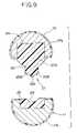
- FIG. 9is a sectional view of a treatment portion showing a variation 4 of the treatment portion in the embodiment 1;
- FIG. 10is a sectional view of a treatment portion showing a variation 5 of the treatment portion in the embodiment 1;
- FIG. 11is a side view showing the entire construction of the treatment device according to an embodiment 2 of the present invention.
- FIG. 12is a sectional view taken on D-D line in FIG. 11 ;
- FIG. 13is a sectional view of a treatment portion showing a variation 1 of the treatment portion in the embodiment 2;
- FIG. 14is a circuit diagram showing a specific configuration of a switching portion for switching a high-frequency current flowing through each electrode portion of the treatment portion;
- FIG. 15is a timing chart showing an operating state when switching control of the high-frequency current is performed by the switching portion in FIG. 14 ;
- FIG. 16is an explanatory view for explaining a treatment of a living tissue by the treatment portion of the variation 1 in the embodiment 2;
- FIG. 17is a schematic diagram of a living tissue treated by the treatment portion of the variation 1 in the embodiment 2;
- FIG. 18is a sectional view of the treatment portion showing the variation 2 of the treatment portion in the embodiment 2;
- FIG. 19is an explanatory view showing a state where the living tissue is coagulation/treated to explain a treatment action by the treatment portion in FIG. 18 ;
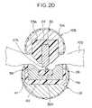
- FIG. 20is an explanatory view showing a state where the living tissue is incised/treated from the state shown in FIG. 19 ;
- FIG. 21is an explanatory view showing a state where the living tissue has been incised/treated from the state shown in FIG. 20 ;
- FIG. 22is a graph showing impedance change of the living tissue at treatment
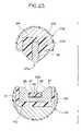
- FIG. 23is a sectional view of the treatment portion showing the variation 3 of the treatment portion in the embodiment 2;
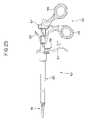
- FIG. 24is a side view showing a construction of forceps suitable for a surgery under endoscope to which the treatment device in the embodiment 1 and the embodiment 2 can be applied;
- FIG. 25is a side view showing the entire construction of the treatment device according to an embodiment 3 of the present invention.
- FIG. 26is a configurational view of the treatment portion provided at the tip end side of an insertion portion of the treatment device
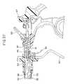
- FIG. 27is a configurational view of an operation portion showing a state before an operation lever of the operation portion is operated
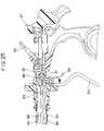
- FIG. 28is a configurational view of the operation portion showing a state where the operation lever is operated to the hand side from the state shown in FIG. 27 ;
- FIG. 29is an explanatory view showing a state where the high-frequency current flows at the hand side of an electrode portion for incision to explain action of the electrode portion for incision by the treatment portion;
- FIG. 30is an explanatory view showing a state where the position where the high-frequency current flows is moved to the tip end side of the electrode portion for incision by an elastic force of an elastic member;
- FIG. 31is an explanatory view showing a state where the living tissue is coagulated to explain a treatment of the living tissue by the treatment device of the embodiment 3;
- FIG. 32is an explanatory view showing a state where the living tissue is incised by the electrode portion for incision;
- FIG. 33is an explanatory view showing a state where the living tissue has been incised by the electrode portion for incision from the state shown in FIG. 32 ;
- FIG. 34is a side view showing a specific construction of the treatment device according to a variation of the embodiment 3;
- FIG. 35is a sectional view showing a construction of a treatment portion of a treatment device according to an embodiment 4 of the present invention.
- FIG. 36is an explanatory view showing a state where the high-frequency current flows at the center part of the electrode portion for incision to explain a treatment of the living tissue by the treatment portion;
- FIG. 37is an explanatory view showing a state where the position where the high-frequency current flows is moved to the tip end side and the hand side of the electrode portion for incision by the elastic force;
- FIG. 38is a sectional view showing a specific construction of a treatment device according to a variation of the embodiment 4.
- FIG. 39is a sectional view showing a construction of a treatment portion of a treatment device according to an embodiment 5 of the present invention.
- FIG. 40is a sectional view taken on A-A line in FIG. 39 ;
- FIG. 41is an explanatory view showing a state where the high-frequency current flows at the tip end side and the hand side of the treatment portion to explain a treatment of the living tissue by the treatment portion;
- FIG. 42is an explanatory view showing a state where the position where the high-frequency current flows is moved to the center part of the treatment portion by elastic force of a linear elastic body.
- FIG. 43is a sectional view showing a specific construction of a treatment device according to a variation of the embodiment 5.
- FIGS. 1 to 5relate to an embodiment 1 of the present invention, in which FIG. 1 is a side view showing an entire construction of a treatment device according to the embodiment 1, FIG. 2 is a sectional view taken on A-A line in FIG. 1 , FIG. 3 is a configurational view of a jaw seen from the arrow B direction in FIG. 1 , FIG. 4 is a configurational view of the other jaw seen from the arrow C direction in FIG. 1 , and FIG. 5 is an explanatory view for explaining a treatment of a living tissue by the treatment device in FIG. 1 .
- high-frequency energy(electric energy) is used as energy for treatment of a living tissue
- a case of construction as a high-frequency treatment device for performing treatments such as coagulation of a living tissue, incision, ablation of the living tissue or the like using this high-frequency energywill be explained.
- a treatment device 1comprises forceps 2 and a high-frequency cautery power supply device (hereinafter abbreviated simply as a power supply device) 3 detachably connected to the forceps 2 , for driving/controlling the forceps 2 by outputting a high-frequency power, which is a power supply power, to the forceps 2 .
- a power supply devicehereinafter abbreviated simply as a power supply device
- the forceps 2has a connector provided at a rear end of a connection cord 4 extending from the hand side detachably connected to the power supply device 3 . And to this power supply device 3 , a foot switch 5 is electrically connected through a connection cord 5 a.
- the foot switch 5comprises, for example, a first operation pedal 6 for instructing operation to turn on/off of a coagulation incision mode for performing coagulation and incision of a living tissue and a second operation pedal 7 for instructing operation of turning on/off of a coagulation mode for coagulating the living tissue.
- the foot switch 5generates an operation signal when the first and the second pedals 6 , 7 are operated and outputs it to the power supply device 3 through the connection cord 5 a .
- the power supply device 3controls on/off of a high-frequency power to be supplied to the forceps 2 based on the operation signal from the foot switch 5 . That is, on/off of the high-frequency power to the forceps 2 is controlled by the power supply device 3 when an operator operates on/off of the first pedal 6 or the second pedal 7 of the foot switch 5 .
- the coagulation/incision modeis a mode that, if the living tissue is a blood vessel, for example, a high-frequency power is supplied that is required for coagulation and hemostasis of a predetermined range of the blood vessel and then, for incision of a coagulated portion of this blood vessel while leaving the both side portions whose bleeding was stopped.
- the coagulation modeis a mode to supply a high-frequency power required to coagulate and stop bleeding of a predetermined portion of a blood vessel and to bring it to a state not reaching incision.
- these modesare not automatically executed by the power supply device 3 but as mentioned above, the coagulation/incision mode or the coagulation mode is executed by the on/off operation of the first pedal 6 or the second pedal 7 of the foot switch 5 while the operator is visually checking the state of coagulation or incision of the living tissue at a treatment of the living tissue.
- the forceps 2mainly comprises a pair of handle portions 8 , 9 to be held and operated by the operator, a pair of jaws 10 , 11 for gripping the living tissue to be treated for coagulation and incision, and a pair of forceps constituting portions 12 , 13 connecting the pair of handle portions 8 , 9 and the pair of jaws 10 , 11 .
- the pair of jaws 10 , 11constitute a treatment portion 14 for performing coagulation, incision or the like while gripping the living tissue.
- the pair of forceps constituting portions 12 , 13are provided between the handle portions 8 , 9 and the jaws 10 , 11 , respectively. And the pair of forceps constituting portions 12 , 13 are overlapped with each other with the middle portions substantially crossing each other. Moreover, at the crossing portion where the pair of forceps constituting portions 12 , 13 are overlapped with each other, a fulcrum pin 15 for connecting the pair of forceps constituting portions 12 , 13 capable of rotational movement is provided.
- rings 16 , 17 for finger insertionare provided in which the fingers of the operator are put.
- the pair of jaws 10 , 11are opened/closed in an interlocking manner so that the living tissue is gripped, separated, pressed or ejected. That is, the pair of handle portions 8 , 9 and the pair of forceps constituting portions 12 , 13 constitute an operation portion 18 of the forceps 2 .
- the jaw 10 in this embodimentis provided with a first electrode portion 19 and a second electrode portion 20 (See FIG. 2 ), which will be described later. Inside the forceps constituting portion 12 , lead wires 21 , 22 electrically connected to the first electrode portion 19 and the second electrode portion 20 , respectively, are disposed.
- These lead wires 21 , 22extends from the jaw 10 to the handle portion 8 and is electrically connected to the power supply device 3 from a cord connection portion 23 at the rear end side of the ring 16 through the connection cord 4 .
- the pair of jaws 10 , 11 constituting the treatment portion 14 of the forceps 2are formed in the tapered shape curved toward the tip end portion.
- a long-groove state recess portion 24is formed on a surface of the jaw 10 opposite to the other jaw 11 .
- an insulating member 25 formed of an electrically insulating materialis fixed.
- this insulating member 25is formed using a material such as ceramics with favorable electrical insulation and high heat resistance (alumina, aluminum nitride, zirconia), plastic (polytetrafluoroethylene (PTFE)), polyether ether ketone (PEEK)), etc.
- the materialis not limited to them but any material with favorable electrical insulation and high heat resistance will do.
- the first electrode portion 19 and the second electrode portion 20are fixed in the electrically insulated state by the wall portion 26 .
- the first electrode portion 19 and the second electrode portion 20are arranged along the curved shape in the longitudinal direction of the jaw 10 .
- the first electrode portion 19is a positive pole in this embodiment
- the second electrode portion 20is a negative pole and high-frequency power flows between these first and second electrode portions 19 , 20 .
- the first electrode portion 19 and the second electrode portion 20are formed using a metal material such as stainless or copper having electric conductivity. Also, in order to improve electric conductivity, it may be so constituted that the outer surfaces of the first electrode portion 19 and the second electrode portion 20 are coated with gold plating or the like.
- the surface of the first electrode portion 19 , the second electrode portion 20 and the wall portion 26 opposite to the other jaw 11is formed as a tissue pressing portion 27 in a relatively dull shape, an arc, for example.
- a tissue pressing portion 27in a relatively dull shape, an arc, for example.
- the width W of the tissue pressing portion 27is approximately 2 mm and the radius of an R portion forming the arc shape at the tip end portion is approximately 1 mm.
- the numeral valuesare not limited to them.
- the tissue pressing portion 27constitutes the projection portion.
- a receiving member 28is integrally provided at the other jaw 11 at a position opposite to the tissue pressing portion 27 of the jaw 10 .
- a groove portion 29 in the substantially same shape as that of the tissue pressing portion 27is formed.
- the receiving member 28is formed using a resin material with favorable electrical insulation and high heat resistance such as polytetrafluoroethylene (PTFE).
- the pair of jaws 10 , 11 in this constructionare formed using a metal material such as stainless, the respective outer surfaces are, as shown in FIG. 2 , covered and constituted by insulating members 10 a , 11 a formed of an electrically insulating material (such as polytetrafluoroethylene (PTFE) or alumina).
- insulating members 10 a , 11 aformed of an electrically insulating material (such as polytetrafluoroethylene (PTFE) or alumina).
- the wall portion 26is integrally constructed with the insulating member 25 , but not limited to this, the wall portion 26 may be constructed as a member separate from the insulating member.
- the operatorinserts the two fingers in the rings 16 , 17 for finger insertion of the operation portion 18 of the forceps 2 and operates rotational movement of these two rings 16 , 17 in the opening direction.
- the two jaws 10 , 11 of the forceps 2are opened.
- the operatorperforms positioning so that a living tissue 100 to be treated is disposed between the opened jaws 10 , 11 .
- the operatoroperates rotational movement of the two rings 16 , 17 in the closing direction in that state to grip the living tissue 100 between the tissue pressing portion 27 and the receiving member 28 .
- the living tissue 100is gripped between the tissue pressing portion 27 and the receiving member 28 in the strongly compressed state.
- the operatorgrips the living tissue 100 and then, selectively turns on the first operation pedal 6 , the second operation pedal 7 of the foot switch 5 so as to start coagulation or incision treatment.
- the power supply device 3is driven under a first output condition preset in order to perform the coagulation/incision mode
- the power supply device 3is driven under a second output condition preset in order to perform the coagulation mode.
- the high-frequency current(300 kHz to 10 MHz, for example) flows between the two first and the second electrode portions 19 , 20 from the power supply device 3 through the connection cord 4 , the cord connection portion 23 and the lead wires 21 , 21 . That is, these forceps 2 function as the bipolar type high-frequency treatment instruments.
- the power supply device 3controls to turn on supply of the high-frequency power to the forceps 2 . Specifically, the power supply device 3 controls so that the high-frequency current with an incision waveform (continuous sinusoidal wave) flows between the two electrode portions 19 , 20 .
- the high-frequency currentflows through the gripped living tissue 100 along the path as shown by an arrow in FIG. 5 .
- Joule heatis generated locally and continuously.
- the living tissue 100goes through the coagulation process and then, it is incised.
- the living tissue 100reaches a coagulation action temperature and then, reaches to an incision action temperature higher than that.
- incisioncan be performed quickly while the living tissue 100 is sufficiently coagulated.
- both sides of the incision portion to be incised of the living tissue 100are left with the coagulated portion whose bleeding was sufficiently stopped.
- the power supply device 3control so that supply of the high-frequency power to the forceps 2 is turned on. Specifically, the power supply device 3 controls so that the high-frequency current with the coagulation waveform (burst waveform) flows between the two electrode portions 19 , 20 .
- the flowing currentis in the coagulation waveform (burst waveform)
- Joule heatis generated intermittently, and the living tissue 100 does not exceed the incision action temperature higher than the coagulation action temperature after it is reached. That is, the living tissue 100 is not incised, but stronger coagulation is made possible.
- the coagulation portion to be coagulated of the living tissue 100is in the coagulated state having an area whose bleeding is sufficiently stopped.
- a treatment according to the target living tissuecan be performed by one type of forceps 2 . That is, in this embodiment, when a tissue containing a relatively thin blood vessel is to be treated, for example, the first operation pedal 6 is operated for coagulation, incision under the first output condition preset for performance of the coagulation/incision mode. Alternatively, when a tissue containing a relatively thick blood vessel is to be treated, it is only necessary that the second operation pedal 7 is operated, and firm coagulation is performed under the second output condition preset for performance of the coagulation mode.
- coagulation and incision of the living tissuecan be performed in a short time and surely.
- a treatment according to the target living tissuecan be performed by one type of forceps 2 .
- the living tissueis incised by conducting the high-frequency current between the two electrode portions 19 , 20 , it is not necessary to perform an incision treatment using a sharp blade of a knife in the conventional technique. That is, since edge will not deteriorate and reuse of the forceps 2 is made possible, costs can be reduced more than conventional examples.
- the forceps 2 of the embodiment 1has more freedom in the shape of the treatment portion 14 (the pair of jaws 10 , 11 ) as compared with the case of incision operation by movement of the knife as in the conventional technique. By this, it becomes possible to form the shape of the treatment portion according to applications (curved shape, for example).
- the treatment portion 14may be constructed as shown in variations 1 to 5, which will be described later.
- FIGS. 6 to 10The variations 1 to 5 of the embodiment 1 will be described referring to FIGS. 6 to 10 .
- the same reference numeralsare given to the same components as those in the treatment device in the embodiment 1 and the explanation will be omitted, and only differences will be described.
- FIG. 6is a sectional view of a treatment portion showing the variation 1 of the treatment portion in the embodiment 1.
- the treatment portion 14 of the embodiment 1may be constructed as shown in the variation 1 in FIG. 6 , for example. That is, as shown in FIG. 6 , the jaw 11 constituting the treatment portion 14 comprises a receiving member 28 A with a different material in place of the receiving member 28 of the embodiment 1.
- This receiving member 28 Ais integrally provided at a position of the jaw 11 opposite to the tissue pressing portion 27 of the jaw 10 .
- the surface of this receiving member 28 A opposite to the tissue pressing member 27is formed in the plane state.
- this receiving member 28 Ais formed of a resin material or an elastic material capable of elastic deformation with favorable electrical insulation and high heat resistance, for example.
- the receiving member 28 Ais formed of silicon rubber or fluoro-rubber with JIS A hardness of about 30 to 70°.
- the receiving member 28 A of the jaw 11is formed using a resin material or an elastic material capable of elastic deformation.
- this receiving member 28 Ais elastically deformed by the compression force between the tissue pressing portion 27 and the receiving member 28 A, whereby the living tissue 100 is gripped while being elongated with the elastic deformation of the receiving member 28 A.
- the living tissue 100is surely gripped between the tissue pressing portion 27 and the receiving member 28 A while it is pulled and elongated. Therefore, when the coagulation incision or coagulation treatment is performed by conducting the high-frequency current to the two electrode portions 19 , 20 as with the embodiment 1, the coagulation incision or coagulation treatment can be performed in a shorter time than the embodiment 1.
- FIG. 7is a configurational view of a jaw showing a variation 2 of the treatment device in the embodiment 1.
- the treatment portion 14 of the embodiment 1may be constructed as shown in the variation 2 of FIG. 7 , for example. That is, as shown in FIG. 7 , the treatment portion 14 of the variation 2 comprises a plurality of first electrode portions 19 A and a plurality of second electrode portions 20 A in place of the first electrode portion 19 and the second electrode portion 20 in the embodiment 1.
- the plurality of first electrode portions 19 A and the plurality of second electrode portions 20 Aare provided at the insulating member 25 as in the embodiment 1.
- the plurality of first electrode portions 19 A and the plurality of second electrode portions 20 Aare fixed in the state electrically insulated by the wall portion 26 of the insulating member 25 , respectively. Also, the plurality of first electrode portions 19 A and the plurality of second electrode portions 20 A are fixed while changing the arrangement positions alternately in the longitudinal direction (axial direction of the forceps 2 ) of the forceps 2 , and in the direction orthogonal to the longitudinal direction of the forceps 2 (the direction orthogonal to the axial direction of the forceps 2 ), each of the first electrode portions 19 A and the second electrode portions 20 A are arranged side by side to be opposed to each other. Moreover, the plurality of first electrode portions 19 A have the same potential, and the plurality of second electrode portions 20 A have the same potential.
- the surfaces of the plurality of first electrode portions 19 A, the second electrode portions 20 A and the wall portion 26 opposite to the other jaw 11are integrally formed as the tissue pressing portion 27 in the relatively dull shape as with the embodiment 1, though not shown.
- the plurality of first electrode portions 19 A and the plurality of second electrode portions 20 Aare fixed to the insulating member 25 while changing the arrangement positions alternately in the longitudinal direction (axial direction of the forceps 2 ) of the forceps 2 , and in the direction orthogonal to the longitudinal direction of the forceps 2 (the direction orthogonal to the axial direction of the forceps 2 ), the respective first electrode portions 19 A and the second electrode portions 20 A are arranged opposing to each other side by side.
- the high-frequency currentflows between the adjoining plurality of the first electrode portions 19 A and the plurality of second electrode portions 20 A, respectively.
- the high-frequency currentflows not only between the opposing first electrode portions 19 A and the second electrode portions 20 A but also between the first electrode portion 19 and the second electrode portion 20 A adjoining in the longitudinal direction of the forceps 2 (axial direction of the forceps 2 ).
- an area of the living tissue 100 where the high-frequency current flowsis larger than that of the embodiment 1.
- FIG. 8is a sectional view of a treatment portion showing a variation 3 of the treatment portion in the embodiment 1.
- the treatment portion 14 of the embodiment 1may be constructed as shown in the variation 3 of FIG. 8 , for example. That is, as shown in FIG. 8 , the treatment portion 14 of the variation 3 comprises a first electrode portion 19 B and two electrode portions 20 B with different shapes in place of the first electrode portion 19 and the second electrode portion 20 of the embodiment 1 and an insulating member 25 A with a different shape in place of the insulating member 25 of the embodiment 1.
- the insulating member 25 A formed using an electrically insulating materialis fixed to the recess portion 24 of the jaw 10 .
- a projection portion 30 projecting toward the other jaw 11is formed.
- the first electrode portion 19 Bis fixed, and to the both sides of this first electrode portion 19 B, the two second electrode portions 20 B, 20 B are fixed in the state electrically insulated from the first electrode portion 19 B.
- first electrode portion 19 B and the two second electrode portions 20 B, 20 Bare arranged along the curved shape in the longitudinal direction of the jaw 10 as in the embodiment 1. And the two second electrode portions 20 B, 20 B have the same potential.
- the surfaces of the first electrode portion 19 B, the two second electrode portions 20 B, 20 B and the projection portion 30 opposite to the other jaw 11are integrally formed as the tissue pressing portion 27 in the relatively dull shape as in the embodiment 1.
- the first electrode portion 19 B and the two second electrode portions 20 B, 20 Bare formed as thin print-type various electrode portions, respectively, and moreover, it may be so constructed that these various electrode portions are applied to a recess groove formed on the outer surface of the projection portion 30 of the insulating member 25 A.
- the first electrode portion 19 Bis fixed to the vicinity of the center of the projection portion 30 , and at the both sides of this first electrode portion 19 B, the two second electrode portions 20 B, 20 B are fixed in the state electrically insulated from the first electrode portion 19 B. And the first electrode portion 19 B and the second electrode portions 20 B, 20 B are arranged along the curved shape in the longitudinal direction of the jaw 10 .
- the high-frequency currentflows between the first electrode portion 19 B and the two second electrode portions 20 B, 20 B, respectively.
- the first electrode portion 19 B and the two second electrode portions 20 B, 20 Bcan be made smaller than those in the embodiment 1 in addition to the same effects as in the embodiment 1, and moreover, the insulating member 25 A can be formed as a main body, whereby costs can be reduced.
- FIG. 9is a sectional view of a treatment portion showing a variation 4 of the treatment portion in the embodiment 1.
- the treatment portion 14 of the embodiment 1may be constructed as shown in the variation 4 of FIG. 9 , for example. That is, as shown in FIG. 9 , the treatment portion 14 of the variation 4 comprises the same components as those in the above mentioned variation 3 shown in the FIG. 8 , except that the first electrode portion 19 B and the two second electrode portions 20 B are applied to the outer circumferential surface on the jaw 11 side of the projection portion 30 .
- first electrode portion 19 B and the two second electrode portions 20 B, 20 Bare formed as thin print-type various electrode portions, respectively, and moreover, these various electrode portions are applied to predetermined positions of the outer surface of the projection portion 30 of the insulating member 25 A.
- FIG. 10is a sectional view of a treatment portion showing a variation 5 of the treatment portion in the embodiment 1.
- the treatment portion 14 of the embodiment 1may be constructed as shown in the variation 5 of FIG. 10 , for example. That is, as shown in FIG. 10 , the treatment portion 14 comprises a pair of jaws 10 A, 11 A with different wiring of the lead wires 20 , 21 and construction of the first, the second electrode portions 19 , 20 in place of the pair of jaws 10 , 11 in the embodiment 1.
- a first electrode portion 19 C and a second electrode portion 20 Cwhich will be described later, are provided at the jaw 11 A.
- a receiving member 32is provided at a position opposite to the tissue pressing portion 27 of the jaw 10 A, which will be described later.
- lead wires 21 , 22extend from the jaw 11 A, which is a part of the forceps constituting portion 13 to the handle portion 8 through the fulcrum pin 15 , the inside of the forceps constituting portion 12 , for example, and is electrically connected to the power supply device 3 from the cord connection portion 23 at the rear end side of the ring 16 through the connection portion 4 as in the embodiment 1.
- the lead wires 21 , 22may be constructed to be electrically connected to the power supply device 3 through the connection cord 4 .
- the surface of the jaw 10 A opposite to the other jaw 11 Aforms the tissue pressing portion 27 having a projection portion 31 in the relatively dull shape.
- the jaw 10 Ais formed using a metal material such as stainless, and its outer surface is covered and constructed by the insulating member 10 a formed of an electrically insulating material (polytetrafluoroethylene (PTFE) or alumina) as shown in FIG. 10 .
- PTFEpolytetrafluoroethylene
- the surface of the jaw 11 A opposite to the other jaw 10 Ais formed in the shape with a recessed center portion.
- the receiving member 32is provided at a position opposite to the tissue pressing portion 27 of the jaw 10 A.
- This receiving member 32is formed using a resin material such as polytetrafluoroethylene (PTFE), silicone rubber or the like with favorable electrical insulation and high heat resistance, as in the embodiment 1.
- PTFEpolytetrafluoroethylene
- silicone rubbersilicone rubber
- the first electrode portion 19 C and the second electrode portion 20 Care provided holding the insulating member 33 with electrical insulation between them. That is, the first electrode portion 19 C and the second electrode portion 20 C are electrically insulated by the receiving member 32 and the insulating member 33 .
- the first electrode portion 19 C and the second electrode portion 20 Care formed using a metal material such as stainless, and the outer surfaces are covered and constructed by an insulating member 11 a formed of an electrically insulating material (polytetrafluoroethylene (PTFE) or alumina, for example) except action surfaces 34 , 35 opposite to the jaw 10 A as shown in FIG. 10 .
- a metal materialsuch as stainless
- an insulating member 11 aformed of an electrically insulating material (polytetrafluoroethylene (PTFE) or alumina, for example) except action surfaces 34 , 35 opposite to the jaw 10 A as shown in FIG. 10 .
- PTFEpolytetrafluoroethylene
- the living tissue 100is gripped between the jaw 10 A and the jaw 11 A and gripped in the strongly compressed state between the tissue pressing member 27 and the receiving member 32 .
- the first electrode portion 19 C and the second electrode portion 20 Care provided holding the insulating member 33 with electrical insulation between them. Therefore, the high-frequency current flows between the action surfaces 34 , 35 of the two first electrode 19 C, the second electrode portion 20 C from the power supply device 3 through the connection cord 4 , the cord connection portion 23 and the lead wires 21 , 22 .
- the high-frequency currentflows through the gripped living tissue 100 in an area larger than that in the embodiment 1, and Joule heat is generated locally. And by this Joule heat and the compression force between the tissue pressing portion 27 and the receiving member 32 , coagulation, incision or strong coagulation of the living tissue 100 can be performed in a short time. In this case, incision of the living tissue 100 is performed in the vicinity of the center of the tissue pressing portion 27 .
- FIGS. 11 and 12relate to an embodiment 2 of the present invention, in which FIG. 11 is a side view showing an entire construction of a treatment device according to the embodiment 2 and FIG. 12 is a sectional view taken on D-D line in FIG. 11 . It is to be noted that in FIGS. 11 and 12 , the same components as those in the treatment device 1 of the embodiment 1 are given the same reference numerals so as to omit explanation, and only differences will be described.
- a treatment device 1 A of the embodiment 2has forceps 2 A with construction different from the forceps 2 in the embodiment 1.
- the entire construction of the forceps 2 Ais substantially the same as that of the embodiment 1, but it has a pair of jaws 10 B, 11 B with different construction and forceps constituting portions 12 A, 13 A.
- a first electrode portion 36which will be described later, is provided, while at the other jaw 11 B, a second electrode portion 37 , which will be described later, is provided.
- the construction of the forceps constituting portions 12 A, 13 Ais substantially the same as that of the embodiment 1, but the lead wire 21 electrically connected to the first electrode portion 36 is disposed inside the forceps constituting portion 12 A. Also, inside the forceps constituting portion 13 A, the lead wire 22 electrically connected to the second electrode portion 37 is disposed.
- the lead wire 21extends from the jaw 10 B to a handle portion 8 A and is electrically connected to the power supply device 3 from the cord connection portion 23 on the rear end side of the ring 16 through the connection cord 4 .
- the lead wire 22extends from the jaw 11 B to a handle portion 9 A and is electrically connected to the power supply device 3 from a cord connection portion 23 A on the rear end side of the ring 17 through the connection cord 4 .
- the pair of jaws 10 B, 11 B constituting the treatment portion 14 A of the forceps 2 Aare formed in the curved tapered shape toward the tip end portion as in the embodiment 1. Also, in the embodiment 2, as shown in FIG. 12 , the long-groove state recess portion 24 is formed on the surface of the jaw 10 B opposite to the other jaw 11 B. To this recess portion 24 , the insulating member 25 A formed substantially in the U shape using an electrically insulating material is fixed.
- this insulating member 25 Ais formed using the electrically insulating material substantially the same as that of the insulating member 25 of the embodiment 1.
- the surface of the first electrode portion 36 (surface portion) opposite to the other jaw 11 Bis formed in the relatively dull shape, as an arc-shaped tissue pressing portion 27 A, for example.
- a long-groove state recess portion 40is formed at a position opposite to the tissue pressing portion 27 A of the other jaw 10 B.
- an insulating member 41 formed in the substantially U shape using an electrically insulating materialis fixed.
- the second electrode portion 37is fixed while being covered by this insulating member 41 .
- This insulating member 41is formed using the electrically insulating material substantially the same as that of the insulating member 25 A.
- the surface of the second electrode portion 37 opposite to the jaw 10 Bis formed in the shape with the center portion recessed. Also, at this second electrode portion 37 , the receiving member 32 is integrally provided at a position opposite to the tissue pressing portion 27 A.
- This receiving member 32is formed using a resin material such as polytetrafluoroethylene (PTFE), silicon rubber or the like with favorable electrical insulation and high heat resistance.
- PTFEpolytetrafluoroethylene
- the second electrode portion 37has two action surfaces 38 , 39 formed in the shape conforming to the shape of the insulating member 25 A of the jaw 10 B.
- the pair of jaws 10 B, 11 B in this constructionare formed using a metal material such as stainless, and their respective outer surfaces are covered and constructed by the insulating members 10 a , 11 a formed of an electrically insulating material (polytetrafluoroethylene (PTFE) or alumina, for example) as with the embodiment 1 as shown in FIG. 12 .
- a metal materialsuch as stainless
- the insulating members 10 a , 11 aformed of an electrically insulating material (polytetrafluoroethylene (PTFE) or alumina, for example) as with the embodiment 1 as shown in FIG. 12 .
- PTFEpolytetrafluoroethylene
- the first electrode portion 36is a positive pole, for example, then the second electrode portion 37 is a negative pole, and the high-frequency power flows between the first and the second electrode portions 36 , 37 .
- coagulation, incision treatments of the living tissue 100can be performed by flowing the high-frequency current between each of the action surfaces 38 , 39 of the second electrode portion 37 and the first electrode portion 36 in the state where the living tissue 100 is compressed within a narrow range by the first electrode portion 36 constituting the tissue pressing portion 27 A and the receiving member 32 .
- the treatment device 1 A of the embodiment 2acts substantially similarly to the embodiment 1. That is, in the forceps 2 A of the treatment device 1 A of the embodiment 2, at coagulation, incision treatments, the living tissue 100 is gripped between the jaw 10 B and the jaw 11 B and gripped between the tissue pressing member 27 A and the receiving member 32 in the strongly compressed state.
- the living tissue 100is gripped by the first electrode portion 36 constituting the tissue pressing member 27 A and the receiving member 32 in the state compressed in a narrow range.
- the first electrode portion 36is provided on the jaw 10 B side, while the second electrode portion 37 having the action surfaces 38 , 39 is provided on the other jaw 11 B side. Therefore, the high-frequency current flows between the first electrode portion 36 and the action surfaces 38 , 39 of the second electrode portion 37 from the power supply device 3 through the connection cord 4 , the cord connection portions 23 , 23 A and the lead wires 21 , 22 .
- the high-frequency currentflows through the living tissue 100 gripped in the compressed state in a narrow range in an area larger than the embodiment 1, and Joule heat is generated locally. And by this Joule heat and the compression force between the tissue pressing portion 27 A and the receiving member 32 , coagulation, incision or strong coagulation of the living tissue can be performed in a short time.
- the treatment portion 14 Amay be constructed as shown in variations 1 to 3, which will be described later.
- FIGS. 13 to 23The variations 1 to 3 of the embodiment 2 will be described referring to FIGS. 13 to 23 .
- the same components as those of the treatment device of the embodiment 2are given the same reference numerals to omit description and only the differences will be described in FIGS. 13 to 23 .
- FIGS. 13 to 17show a variation 1 of the treatment portion in the embodiment 2, in which FIG. 13 is a sectional view of the treatment portion of the variation 1,
- FIG. 14is a circuit diagram showing specific construction of a switching portion for switching the high-frequency current flowing to each of the electrode portions of the treatment portion,
- FIG. 15is a timing chart showing an operating state at switching control of the high-frequency current by the switching portion of FIG. 14
- FIG. 16is an explanatory view for explaining treatment of the living tissue by the treatment portion of the variation 1
- FIG. 17is a schematic diagram of the living tissue treated by the treatment portion of the variation 1.
- the treatment portion 14 A of the embodiment 2may be constructed as shown in the variation 1 of FIG. 13 , for example. That is, as shown in FIG. 13 , in the treatment portion 14 A, the construction of the respective electrode portions (the first electrode portion 36 and the second electrode portion 37 ) provided at the jaws 10 B, 11 B constituting this treatment portion 14 A is different.
- the long-groove state recess portion 24is formed on the surface of the jaw 10 B opposite to the other jaw 11 B as in the embodiment 2.
- the insulating member 25 A formed substantially in the U shape using an electrically insulating materialis fixed.
- the first electrode portion 36is fixed while being covered by this insulating member 25 A. Also, the surface (surface portion) of the first electrode portion 36 opposite to the other jaw 11 B is formed in the relatively dull shape, as an arc-shaped tissue pressing portion 27 A, for example.
- the jaw 10 Bis formed using a metal material such as stainless as in the embodiment 2, and this jaw 10 B itself is constituted as a third electrode portion 36 A, which will be described later. Moreover, the outer surface of this third electrode portion 36 A is covered and constructed by the insulating member 10 a formed of an electrically insulating material (polytetrafluoroethylene (PTFE) or alumina, for example) as with the embodiment 2 as shown in FIG. 13 .
- PTFEpolytetrafluoroethylene
- the surface of the other jaw 11 B opposite to the tissue pressing portion 27 A of the jaw 10 Bis formed in the shape with the center portion recessed.
- the receiving member 32is integrally provided at a position opposite to the tissue pressing portion 27 A.
- This receiving member 32is formed using a resin material such as polytetrafluoroehylene (PTFE), silicon rubber or the like with favorable electrical insulation and high heat resistance.
- the jaw 11 Bis formed using a metal material such as stainless as with the embodiment 2, and this jaw 11 B itself is constituted as the second electrode portion 37 A. Also, the outer surface of this third electrode portion 36 A is covered and constructed by an insulating member 11 a formed of an electrically insulating material (polytetrafluoroethylene (PTFE) or alumina, for example) as with the embodiment 2 as shown in FIG. 13 .
- PTFEpolytetrafluoroethylene
- the second electrode portion 37 Ais formed in the shape conforming to the shape of the insulating member 25 A of the jaw 10 B and the third electrode portion 36 A (respective action surfaces 42 , 43 ) and has two action surfaces 44 , 45 not covered by the insulating member 11 a.
- action surfaces 44 , 45have action portions 44 a , 45 a formed at positions opposite to the action surfaces 42 , 43 of the third electrode portion 36 A, respectively, and action portions 44 b , 45 b arranged between these action portions 44 a , 45 a and the receiving member 32 and formed at positions opposite to the insulating member 25 A.
- the construction of the forceps constituting portions 12 A, 13 Ais substantially the same as that of the embodiment 2, but the lead wire 21 electrically connected to the first electrode portion 36 is disposed in the forceps constituting portion 12 A. Moreover, in the variation 1, a lead wire 21 A electrically connected to the jaw 10 B, that is, the third electrode portion 36 A is disposed inside the forceps constituting portion 12 A.
- the lead wire 22 electrically connected to the jaw 11 B, that is, the second electrode portion 37 Ais disposed.
- the lead wires 21 , 21 Aextend from the jaw 10 B to the handle portion 8 A and are electrically connected to the power supply device 3 from the cord connection portion 23 at the rear end side of the ring 16 through the connection cord 4 .
- the lead wire 22extends from the jaw 11 B to the handle portion 9 A and is electrically connected to the power supply device 3 from the cord connection portion 23 A at the rear end side of the ring 17 through the connection cord 4 .
- a switching portion 3 A(See FIG. 11 ) is provided as switching means for switching the high-frequency current flowing to the respective electrode portions (first, second and third electrode portions 36 , 37 A, 36 A) of the treatment portion 14 A.
- This switching portion 3 Ahas a switch 50 having three SW 1 , 2 , 3 electrically connected to a high-frequency power source and the respective electrode portions (first, second and third electrode portions 36 , 37 A, 36 A) of the jaws 10 B, 11 B for turning on/off supply of the high-frequency current from the high-frequency power source and a CPU 51 as control means for performing switching control of this switch 50 based on an operation signal from the foot switch 5 as shown in FIG. 14 .
- the CPU 51controls switching of the switch 50 based on the operation signal from the foot switch 5 .
- the foot switch 5supplies an operation signal indicating instruction of coagulation, incision automatic mode execution to the CPU 51 or by turning on the second operation pedal 7 , it supplies an operation signal indicating instruction of the coagulation mode execution to the CPU 51 .
- the CPU 51control to turn on the SW 1 and the SW 3 of the switch 50 so that the high-frequency current flows through the third electrode portion 36 A of the jaw 10 B and the second electrode portion 37 A of the jaw 11 B at a time t 0 as shown in FIG. 15 .
- the high-frequency currentflows between the third electrode portion 36 A of the jaw 10 B and the second electrode portion 37 A of the jaw 11 B (first current path) under a first output condition preset to execute the coagulation mode, for example, so as to perform the coagulation treatment of the living tissue 100 .
- the CPU 51controls to turn off the SW 1 of the switch 50 so that the high-frequency current flows to the first electrode portion 36 of the jaw 10 B and the second electrode portion 37 A of the jaw 11 B at a time t 1 as shown in FIG. 15 and to turn on the SW 2 as well as the SW 3 at the same time.
- the high-frequency currentflows to the first electrode portion 36 of the jaw 10 B and the second electrode portion 37 A of the jaw 11 B (second current path) under a second output condition preset to execute the coagulation, incision mode, for example, so as to perform the incision treatment of the living tissue 100 .
- the CPU 51controls to turn on the SW 1 and the SW 3 of the switch 50 so that the high-frequency current flows to the third electrode portion 36 A of the jaw 10 B and the second electrode portion 37 A of the jaw 11 B substantially similarly to the above coagulation, incision automatic mode as shown in FIG. 15 .
- the high-frequency currentflows between the third electrode portion 36 A of the jaw 10 B and the second electrode portion 37 A of the jaw 11 B under the first output condition preset to execute the coagulation mode, for example, substantially similarly to the coagulation operation when the above coagulation, incision automatic mode is executed so as to perform the coagulation treatment of the living tissue 100 .
- the CPU 51controls to turn off the SW 1 of the switch 50 and to turn on the SW 3 and the SW 2 so as to automatically execute the above coagulation, incision automatic mode.
- the living tissue 100is gripped between the jaw 10 B and the jaw 11 B at the coagulation, incision treatments as with the embodiment 2.
- the living tissue 100is gripped in the state strongly compressed between the tissue pressing member 27 A and the receiving member 32 , and the action surfaces 42 , 43 of the third electrode portion 36 A and the action surfaces 44 , 45 of the second electrode portion 37 A.
- the operatorgrips the living tissue 100 and then, operates to selectively turn on the first operation pedal 6 , the second operation pedal 7 of the foot switch 5 so as to start the coagulation, and incision treatments.
- the power supply device 3is driven under the first output condition preset to execute the coagulation, incision automatic mode by turning on the first operation pedal 6 , while the power supply device 3 is driven under the second output condition preset to execute the coagulation mode by turning on the second operation pedal 7 .
- the first output conditionhas a first set value required to coagulate the living tissue and a second set value required to incise the living tissue, and this first set value is substantially the same as the second output condition required to execute the above coagulation mode.
- the operatoroperates to turn on the first operation pedal 6 of the footswitch 5 , for example, to execute the coagulation, incision automatic mode. Then, the power supply device 3 controls to turn on supply of the high-frequency power to the forceps 2 A.
- the CPU 51 of the power supply device 3controls to turn on the SW 1 and the SW 3 of the switch 50 so that the high-frequency current with the coagulation waveform (burst wave) flows between the third electrode portion 36 A of the jaw 10 B and the second electrode portion 37 A of the jaw 11 B (first current path) at the time t 0 .
- the high-frequency current with the coagulation waveformflows under the first output condition preset to execute the coagulation mode, for example, flows between the third electrode portion 36 A of the jaw 10 B and the second electrode portion 37 A of the jaw 11 B.
- the high-frequency currentflows through the gripped living tissue 100 through the first current path as shown by an arrow a in FIG. 16 .
- Joule heatis generated locally and intermittently.
- the living tissue 100is strongly coagulated in the first current path shown by the arrow a in FIG. 16 .
- the CPU 51 of the power supply device 3controls to turn off the SW 1 of the switch 50 and to turn on the SW 3 as well as the SW 2 at the same time so that the high-frequency current with the incision waveform (continuous sinusoidal wave) flows between the first electrode portion 36 of the jaw 10 B and the second electrode portion 37 A of the jaw 11 B at the time t 1 as shown in FIGS. 14 and 15 .
- the high-frequency current with the incision waveformflows between the first electrode portion 36 of the jaw 10 B and the second electrode portion 37 A of the jaw 11 B under the second output condition preset to execute the incision mode, for example.
- the high-frequency currentflows through the second current path as shown by an arrow b in FIG. 16 .
- Joule heatis generated locally and continuously.
- the living tissue 100is incised in the vicinity at the center of the tissue pressing portion 27 A.
- incisioncan be performed quickly in the state where the living tissue 100 is sufficiently coagulated.
- Switching from the first current path to the second current pathis automatically controlled by the switching portion 3 A (specifically the CPU 51 ) in the power supply deice 3 shown in FIG. 14 as mentioned above.
- the switching portion 3 Aspecifically the CPU 51
- switching from the coagulation mode to the incision mode by the CPU 51 of the switching portion 3 Ais performed based on an elapsed time from start of output (time from the time t 0 to the time t 1 in FIG. 15 ) or the change in impedance in the living tissue 100 as mentioned above, specifically the change in impedance in the first current path.
- FIG. 17a schematic diagram of the living tissue when treated in the coagulation, incision automatic mode is shown in FIG. 17 . That is, when treated by executing the coagulation, incision automatic mode, as shown in FIG. 17 , an area A of the living tissue 100 is a coagulation range by the first current path, while an area B is an incision range by the second current path.
- the power supply device 3controls to turn on supply of the high-frequency power to the forceps 2 A.
- the CPU 51 of the power supply device 3controls to turn on the SW 1 and the SW 3 of the switch 50 so that the high-frequency current with the coagulation waveform (burst wave) flows between the third electrode portion 36 A of the jaw 10 B and the second electrode portion 37 A of the jaw 11 B (first current path) (See FIGS. 14 and 15 ).
- the high-frequency current with the coagulation waveformflows between the third electrode portion 36 A of the jaw 10 B and the second electrode portion 37 A of the jaw 11 B under the first output condition preset to execute the coagulation mode, for example.
- the high-frequency currentflows through the gripped living tissue 100 through the first current path as shown by the arrow a in FIG. 16 .
- Joule heatis generated locally and intermittently.
- the living tissue 100is strongly coagulated in the first current path shown by the arrow a in FIG. 16 .
- the high-frequency current with the incision waveformdoes not flow between the first electrode portion 36 and the second electrode portion 37 A.
- the living tissue 100 sis not incised but stronger coagulation is made possible.
- treatment according to the target living tissuecan be performed by one type of the forceps 2 .
- the variation 1it may be so constructed and controlled so that the high-frequency current flows in combination of the current paths and the waveforms other than those mentioned above. It may be so constituted, for example, that the second electrode portion 37 A and the third electrode portion 36 A have the same potential and the high-frequency current with the incision waveform flows between them and the first electrode portion 36 .
- the same effects as those of the embodiment 2can be obtained and moreover, execution of the incision, coagulation execution mode is made possible in which the coagulation mode and the incision mode are automatically switched.
- FIGS. 18 to 22show a variation 2 of the treatment portion in the embodiment 2, in which FIG. 18 is a sectional view of a treatment portion of the variation 2, FIGS. 19 to 21 are explanatory views for explaining treatment action by the treatment portion in FIG. 18 , in which FIG. 19 shows a state where a living tissue is coagulated/treated, FIG. 20 shows a state where the living tissue is incised/treated from the state shown in FIG. 19 , and FIG. 21 shows a state where the living tissue is incised/treated from the state shown in FIG. 20 , respectively. Also, FIG. 22 is a graph showing impedance change of the living tissue at treatment.
- the treatment portion 14 A of the embodiment 2may be constructed as shown in the variation 2 of FIG. 18 , for example. That is, as shown in FIG. 18 , the jaw 11 B constituting the treatment portion 14 A comprises a receiving member 32 A with a different material in place of the receiving member 32 in the embodiment 2.
- this receiving member 32 Ais substantially the same as that of the embodiment 2, but this receiving member 32 A is formed of a conductive resin material or an elastic material having a relatively high resistance rate, for example.
- the receiving member 32 Ais formed of conductive silicon rubber, conductive polytetrafluoroehylene (PTFE) or the like.
- the electric resistance of this receiving member 32 Ais approximately 500 ⁇ to 1000 ⁇ , for example.
- the power supply device 3has the switching portion 3 A (See FIG. 14 ) as with the variation 1.
- the SW 2 shown in FIG. 14is electrically connected to the first electrode portion 36
- the SW 3is electrically connected to the second electrode portion 37 .
- the CPU 51 of this switching portion 3 Adetects impedance of the living tissue 100 between the first electrode portion 36 and the second electrode portion 37 at output so as to control on/off of the SW 2 , the SW 3 so that the high-frequency current flows or the high-frequency current does not flow between the first electrode portion 36 and the second electrode portion 37 A based on the comparison result between this impedance and a predetermined threshold value (predetermined value Z 1 ), which will be described later.
- the CPU 51detects the current value I flowing to the switch 50 and calculates the impedance based on this detected current value I and the applied voltage value V of this high-frequency power source.
- the living tissue 100is gripped between the jaw 10 B and the jaw 11 B as with the embodiment 2. At this time, as shown in FIG. 19 , the living tissue 100 is gripped between the tissue pressing member 27 A and the receiving member 32 A in the strongly compressed state.
- the operatorgrips the living tissue 100 and then, the operator selectively operates to turn on the first operation pedal 6 , the second operation pedal 7 of the foot switch 5 so as to start coagulation and incision treatments.
- the power supply device 3is driven under the first output condition preset to execute the coagulation, incision mode, while by operating to turn on the second operation pedal 7 , the power supply device 3 is driven under the second output condition preset to execute the coagulation mode.
- the operatoroperates to turn on the first operation pedal 6 of the foot switch 5 , for example, to execute the coagulation, incision mode. Then, the power supply device 3 controls to turn on supply of the high-frequency power to the forceps 2 A.
- the CPU 51 of the power supply device 3controls to turn on the SWs 2 , 3 of the switch 50 so that the high-frequency current (continuous sinusoidal wave) flows between the first electrode portion 36 of the jaw 10 B and the second electrode portion 37 of the jaw 11 B (first current path) as shown in FIGS. 14 and 19 .
- the high-frequency current with incision waveform(continuous sinusoidal wave) flows between the first electrode portion 36 of the jaw 10 B and the second electrode portion 37 of the jaw 11 B under the first output condition preset to execute the coagulation, incision mode, for example.
- the high-frequency currentflows through the gripped living tissue 100 in the first current path as shown by the arrow a in FIG. 19 .
- Joule heatis generated locally and continuously.
- the characteristic of impedance change of the living tissue 100 from this timeis shown in FIG. 22 . That is, as shown in FIG. 22 , the impedance of the living tissue 100 has a characteristic of rising once immediately after output start (time t 0 ) and dropping and then, continuing to rise.
- This predetermined value Z 1is substantially equal to the impedance of the receiving member 32 A.
- the high-frequency current with the incision waveformflows to the second current path (the path through which the high-frequency current flows from the first electrode portion 36 to the second electrode portion 37 through the living tissue 100 and the receiving member 32 A) as shown by the arrow b in FIG. 20 .
- the second current paththe path through which the high-frequency current flows from the first electrode portion 36 to the second electrode portion 37 through the living tissue 100 and the receiving member 32 A.
- the predetermined value Z 1 of the impedance in the first current path(that is, the impedance of the receiving member 32 A) is set so that the living tissue 100 reaches the coagulation action temperature but not the incision action temperature higher than that. By this, the living tissue 100 is strongly coagulated in the first current path as shown by the arrow a in FIG. 19 .
- the living tissue 100is incised as shown in FIG. 21 at a time t 2 (See FIG. 22 ). That is, under the first output condition, the living tissue 100 can be incised quickly in the state it is sufficiently coagulated.
- the first electrode portion 36 and the second electrode portion 37are short-circuited at a portion where the living tissue 100 is partially cut off, the high-frequency current does not flow to the uncut portion and the living tissue 100 is partially left uncut.
- the receiving member 32 Asince the receiving member 32 A has a relatively high electrical resistance, imperfect cutting hardly occurs in the living tissue 100 . By this, sure coagulation, incision are made possible.
- the CUP 51 of the power supply device 3controls to flow the high-frequency current under the first output condition even if the impedance of the living tissue 100 exceeds the predetermined value Z 1 when the coagulation, incision mode is executed by operation instruction of the first operation pedal 6 .
- the power supply device 3controls to turn on supply of the high-frequency power to the forceps 2 A.
- the CPU 51 of the power supply device 3controls to turn on the SWs 2 , 3 of the switch 50 so that the high-frequency current with the incision waveform (continuous sinusoidal wave) flows to the first electrode portion 36 of the jaw 10 B and the second electrode portion 37 of the jaw 11 B (first current path) similarly to the first output condition.
- the high-frequency current with the incision waveformflows between the first electrode portion 36 of the jaw 10 B and the second electrode portion 37 of the jaw 11 B under the second output condition set similarly to the first output condition, for example.
- the impedance of the living tissue 100 in the first current pathrises as shown in FIG. 22 similarly to the above and then, reaches the predetermined value Z 1 .
- the CPU 51 of the power supply device 3compares the detected impedance of the living tissue 100 with the predetermined value Z 1 and recognizes that the impedance of the living tissue 100 has reached the predetermined value Z 1 . Then, the CPU 51 controls to turn off the SWs 2 , 3 of the switch 50 at the time t 1 when the impedance of the living tissue 100 is reached this predetermined value Z 1 . Therefore, the high-frequency current having flown between the first electrode portion 36 of the jaw 10 B and the second electrode portion 37 of the jaw 11 B (first current path) is shut off.
- the living tissue 100is not incised but strongly coagulated in the first current path as shown by the arrow a in FIG. 19 .
- the high-frequency current with the incision waveformcontinuous sinusoidal wave
- the high-frequency current with the coagulation waveformburst wave
- FIG. 23is a sectional view of a treatment portion showing a variation 3 of the treatment portion in the embodiment 2.
- the treatment portion 14 A of the embodiment 2may be constituted as shown in the variation 3 of FIG. 23 , for example. That is, as shown in FIG. 23 , the treatment portion 14 A of the variation 3 comprises the same components as those of the variation 2 shown in the above FIGS. 18 to 21 except a receiving member 32 B with the construction different from that of the receiving member 32 A.
- the receiving member 32 Bcomprises a conductive resin member 46 having low resistance rate and a semiconductive member 47 provided between the second electrode portion 37 and the resin member 46 and formed substantially in the U shape.
- conductive silicon rubber or conductive polytetrafluoroehylene (PTFE) or the likeis used as the material for the resin member 46 and the semiconductive member 47 .
- the electrical resistance of the resin member 46is not more than 10 ⁇ , for example, and the electrical resistance of the semiconductive member 47 is about 500 to 1000 ⁇ , for example.
- the conductive resin member 46may be coated with semiconductive thin film coating of about 500 to 1000 ⁇ , for example.
- the forceps 2 , 2 A of the treatment devices 1 , 1 Amay be applied to forceps 50 in the construction suitable for a surgery under endoscope as shown in FIG. 24 , which will be described later.
- the forceps 50comprises a narrow and lengthy insertion sheath portion 51 , an operation portion 52 connected to the base end of this insertion sheath portion 51 and a treatment portion 53 provided at the tip end of the insertion sheath portion 51 .
- the operation portion 52has a fixed handle 54 and a movable handle 56 mounted to this fixed handle 54 capable of rotational movement through a handle pivotally support shaft 55 .
- an operation portion body 57is integrally formed.
- the insertion sheath portion 51is mounted rotatably in the direction around axis.
- the insertion sheath portion 51has a lengthy outer tube 58 .
- an elongated rod-state driving shaft 59is inserted capable of advance/retreat in the axial direction.
- the base end of this driving shaft 59is connected to the upper end of the movable handle 56 capable of rotational movement.
- the treatment portion 53has a pair of jaws 60 , 61 capable of opening/closing.
- the tip end portion of the driving shaft 59is connected to the jaws 60 , 61 through a driving mechanism, not shown.
- a driving mechanismnot shown.
- the jaws 60 , 61are constructed in any one of the constructions of the above embodiment 1, the variations 1 to 5 of the embodiment 1, the above embodiment 2 and the variations 1 to 3 of the embodiment 2.
- the first electrode portion 19 and the second electrode portion 20are provided at the jaw 60 at positions opposite to the jaw 61 in the state electrically insulated by the insulating member 25 , respectively.
- the receiving member 28is integrally provided at a position opposite to the jaw 60 .
- the lead wires 21 , 22 electrically connected to the first electrode portion 19 and the second electrode portion 20 , respectively, as with the embodiment 1,are provided.
- a cord connection portion 62is provided at the operation portion body 57 .
- the base ends of the lead wires 21 , 22are connected.
- one end of a connection cord 63is connected to the outer end of the cord connection portion 62 . The other end of this connection cord 63 is electrically connected to the power supply device 3 as with the embodiment 1.
- the above constructionwas described for the case applied to the embodiment 1, but if it is applied to one of the other constructions of the variations 1 to 5 of the embodiment 1, the above embodiment 2 and the variations 1 to 3 of the embodiment 2, the first to the third electrode portions and the lead wires are also constructed according to the case as mentioned above.
- the operatorWhen the living tissue is to be treated using the forceps 50 in FIG. 24 , the operator introduces the treatment portion 53 and the tip end of the insertion sheath portion 51 of the forceps 50 through a trocar or the like, not shown, punctured into a body wall.
- the operatoropens the movable handle 56 and operates to open the jaws 60 , 61 as shown by a virtual line in FIG. 24 so as to position the living tissue between these jaws 60 , 61 .
- the operatoroperates the movable handle 56 in the closing direction so as to grip the living tissue between the jaw 60 and the jaw 61 .
- the operatorAfter gripping the living tissue, the operator selectively operates to turn on the first operation pedal 6 , the second operation pedal 6 of the foot switch 5 so as to perform coagulation, incision of the living tissue as with the embodiment 1.
- the high-frequency currentflows between the two first electrode portion 19 , the second electrode portion 20 from the power supply device 3 through the connection cord 63 , the cord connection portion 62 and the lead wires 21 , 22 as in the embodiment 1.
- the high-frequency currentflows between the respective electrode portions similarly to the construction and action in the embodiment 2.
- FIGS. 25 to 33relate to an embodiment 3 of the present invention, in which FIG. 25 is a side view showing the entire construction of a treatment device according to the embodiment 3, FIG. 26 is a configurational view of a treatment portion provided at the tip end side of an insertion portion of the treatment device, FIGS. 27 and 28 are configurational views of an operation portion provided at the hand side of the treatment device, FIG. 27 shows a state before an operation lever of the operation portion is operated and FIG. 28 shows a state when the operation lever is operated to the hand side from the state shown in FIG. 27 . Also, FIGS. 29 and 30 are explanatory views for explaining the action of an electrode portion for incision by the treatment portion, in which FIG.
- FIGS. 31 to 33show explanatory views for explaining a treatment of the living tissue by the treatment device of the embodiment 3, in which FIG. 31 shows a state where the living tissue is coagulated, FIG. 32 for a state where the living tissue is incised by the electrode portion for incision, and FIG. 33 for the state where the living tissue has been incised by the electrode portion for incision from the state in FIG. 32 .
- a treatment device 60 of the embodiment 3is constituted as a bipolar type coagulation incision tool and comprises a treatment portion 61 provided at the tip end portion for gripping the living tissue for coagulation and incision, an operation portion 62 to be held by an operator when using the treatment device 60 , and an insertion portion 63 for connecting this operation portion 62 to the treatment portion 61 and guiding them into a body cavity.
- a movable handle 66 for opening/closing operation of a pair of coagulation gripping portions 70 , 71 capable of opening/closing provided at the treatment portion 61 , a holding handle 65 for holding the entire treatment device 60 , and a lever 64 for operating an electrode portion 74 for incision, which will be described later,are provided.
- coagulation current conducting terminals 67 , 68 for supplying a coagulating current to the coagulation gripping portions 70 , 71 and an incision current conducting terminal 69 for supplying an incision current to en electrode portion 74 for incisionare provided.
- the coagulation gripping portions 70 , 71 and the incision electrode portion 74are provided around a pin 75 capable of rotational movement.
- the pair of coagulation gripping portions 70 , 71are connected to a link member 80 and a link 81 at the hand side through pins 76 and 77 capable of rotational movement.
- the ling member 80 and the link member 81are connected to a connecting member 84 provided at the distal end of a coagulation gripping portion driving member 88 (See FIG. 27 ) connected to the movable handle 66 through a pin 82 capable of rotational movement.
- the lever 64is connected to a slotted hole 78 provided at the hand side of the incision electrode portion 74 through an incision electrode driving shaft 83 , an engagement portion 79 .
- an abutting member 86formed of an insulating material movable in the longitudinal axis direction is provided around the coagulation gripping portion driving shaft 88 .
- This abutting member 86is urged to the tip end side by an elastic member 87 in a coil spring state.
- the elastic member 87is not limited to the coil spring state but it may be so constructed so as to urge the abutting member 86 to the tip end side.
- the incision current conducting terminal 69 , the incision electrode driving shaft 83 , the engagement portion 79 and the incision electrode portion 74 comprising the slotted hole 78are electrically connected.
- the pin 75 and the pin 82are formed of an insulating material such as alumina, zirconia or the like, for example.
- the coagulation gripping portions 70 , 71 and the incision electrode portion 74are electrically insulated by an insulating member so that they do not conduct electricity to each other in the vicinity of the pin 75 and the pin 82 .
- the insertion portion 63has, as shown in FIG. 27 , its surface covered by an insulating tube 85 and a metal pipe 90 inside it is electrically connected to the coagulation gripping portion 70 and the coagulation current conducting terminal 68 .
- the coagulation gripping portion driving shaft 88 connected to the connecting member 84is covered by an insulating cover 89 over the entire length and electrically connected to the coagulation current conducting terminal 67 , the link member 80 and the coagulation gripping portion 71 .
- connection cord 4 from the power supply device 3 in the embodiment 1is connected to the coagulation current conducting terminals 67 , 68 and the incision current conducting terminal 69 in advance.
- the operatorinserts the insertion portion 63 of the treatment device 60 into a body cavity and moves the treatment portion 61 to the vicinity of a living tissue to be incised/treated. And when the operator opens the movable handle 66 in the opening direction, the coagulation gripping portion driving member 88 is moved in the distal direction and the link member 80 and the link member 81 are rotationally moved in the opening direction around the pin 82 provided at the connecting member 84 . As a result, the coagulation gripping portion 70 and the coagulation gripping portion 71 are opened around the pin 75 .
- the operatorarranges the living tissue between the coagulation gripping portion 70 and the coagulation gripping portion 71 and closes the movable handle 66 and holds tight.
- the coagulation gripping portion driving member 88is moved in the proximate direction and the link member 80 and the link member 81 are rotationally moved in the closing direction around the pin 82 provided at the connecting member 84 .
- the coagulation gripping portion 70 and the coagulation gripping portion 71are rotationally moved around the pin 75 and closed.
- the high-frequency current with the coagulation waveformis supplied from the power supply device 3 to the coagulation current conducting terminal 68 through the connection cord 4 and the high-frequency current with the coagulation waveform is further conducted from this coagulation current conducting terminal 68 through the metal pipe 90 , the coagulation gripping portion 70 to the living tissue.
- the high-frequency current with the coagulation waveform conducting from the coagulation gripping portion 70 to the living tissue 100flows to the other coagulation gripping portion 71 , and the living tissue 100 is coagulated by Joule heat when the current passes through the living tissue 100 .
- the high-frequency current having flown to the coagulation gripping portion 71reaches the link member 80 , the coagulation gripping portion driving member 88 , the coagulation current conducting terminal 67 and is recovered by the power supply device 3 .
- the foot switch 5is operated to supply the high-frequency current with the incision waveform from the power supply device 3 to the incision current conducting terminal 69
- the high-frequency current with the incision waveformflows to the living tissue 100 having been coagulated in advance through the incision electrode driving shaft 83 , the engagement portion 79 , the incision electrode portion 74 .
- the high-frequency current with the incision waveformreaches from the living tissue 100 to the coagulation gripping portion 71 , the link member 80 , the coagulation gripping portion driving member 88 , the coagulation current conducting terminal 67 and is finally recovered by the power supply device 3 . Also, since the insulating members 72 , 73 are provided at the coagulation gripping portions 70 , 71 , the high-frequency current with the incision waveform supplied from the incision electrode portion 74 does not directly flow to the coagulation gripping portions 70 , 71 but is surely supplied to the living tissue 100 .
- the incision operationcan be performed automatically by keeping a certain force by the elastic member 87 , a constant incision operation can be performed easily all the time irrespective of the experience of the operator. Thus, time is not required for coagulation, incision operation of the living tissue and manipulability can be improved.
- the treatment device 60 according to the embodiment 3may be constituted as a variation shown in FIG. 34 .
- FIG. 34is a side view showing a specific construction of a treatment device according to a variation of the embodiment 3.
- the treatment device 60 of the embodiment 3comprises, as shown in the variation of FIG. 34 , a latchet 84 is provided to be engaged with the holding handle 65 when holding tight the lever 64 of the operation portion 62 instead of the abutting portion 86 and the elastic member 87 , and the abutting member 86 to abut against a projection portion 87 provided at the holding handle 65 is fixed to the lever 64 by an adhesive or the like at the elastic member 85 formed of rubber or the like so that a reaction force acts from the holding handle 65 .
- the incision electrode portion 74can be held in the urged state with a certain force by holding tight the lever 64 , the living tissue 100 can be incised even after releasing hold of the lever 64 .
- FIGS. 35 to 37relate to an embodiment 4 of the present invention, in which FIG. 35 is a sectional view showing a construction of a treatment portion of a treatment device according to the embodiment 4, FIGS. 36 , 37 are explanatory views for explaining a treatment of a living tissue by the treatment portion, FIG. 36 shows a state where the high-frequency current flows at the center part of an incision electrode portion, and FIG. 37 shows a state where a position where the high-frequency current flows is moved to the tip end side and the hand side of the incision electrode portion by an elastic force, respectively.
- a treatment device 88 of the embodiment 4is constructed as a bipolar type coagulation incision tool and is improved to a construction particularly with the purpose of incision with regard to the treatment portion 61 of the treatment device 60 of the embodiment 1.
- the hand-side operation portion and the opening/closing mechanismare basically the same as those of the embodiment 1 and the explanation will be omitted.
- the treatment device 88has a pair of gripping portions 89 , 90 mounted at the treatment portion at the tip end of an insertion portion, capable of rotational movement with the pin 75 as the fulcrum, and an incision bar 92 is mounted capable of rotational movement at the gripping portion 89 with a pin 91 as the fulcrum in the state urged in a direction separated from the gripping portion 89 .
- This incision bar 92is an elastic member and is formed with the middle part in the longitudinal direction bent at a dull angle so that its angle is directed to the gripping portion 90 .
- this treatment device 88the operator operates the movable handle of the operation portion, not shown, and holds the living tissue 100 between the pair of gripping portions 89 , 90 .
- the high-frequency current with the incision waveformflows from the incision bar 92 through the living tissue 100 to the gripping portion 90 .
- the gripping portion 90may be constructed similarly to the coagulation gripping portion 71 having the insulating member 73 described in FIGS. 31 to 33 in the above embodiment 3.
- the living tissuecan be incised by holding the living tissue 100 with the gripping portion 90 and supplying the high-frequency current with the incision waveform.
- the other effectsare the same as those of the embodiment 3.
- the treatment device 88 of the embodiment 4may be constructed as in a variation shown in FIG. 38 .
- FIG. 38is a sectional view showing a specific construction of the treatment device according to the variation of the embodiment 4.
- an incision bar 96 and an incision bar 97are provided capable of rotational movement with pins 94 , 95 as fulcrums, respectively.
- FIGS. 39 to 42relate to an embodiment 5 of the present invention, in which FIG. 39 is a sectional view showing a construction of a treatment portion of a treatment device according to the embodiment 5, FIG. 40 is a sectional view taken on line A-A in FIG. 39 , and FIGS. 41 and 42 are explanatory views for explaining a treatment of a living tissue, in which FIG. 41 shows a state where the high-frequency current flows to the tip end side and the hand side of the treatment portion, and FIG. 42 shows a state where a position where the high-frequency current flows is moved to the center part of the treatment portion by an elastic force of a linear elastic body.
- a treatment device 101 of the embodiment 5is constructed as a bipolar type coagulation incision tool substantially similar to the treatment device 88 of the embodiment 4, and only differences will be explained.
- the treatment device 101has a hand-side gripping portion 102 and a tip-end side gripping portion 103 mounted at the upper gripping portion capable of rotational movement with a pin 104 as the fulcrum. Also, a linear elastic body 105 is mounted at upper parts of the hand-side gripping portion 102 and the tip-end side gripping portion 103 in the bent state urged in a direction separated from the gripping portion 90 in the vicinity of the center.
- the hand-side gripping portion 102 and the tip-end side gripping portion 103are electrically connected, and their sectional shapes are, as shown in FIG. 40 , formed in the somewhat sharp shape on the gripping surface side.
- the operatoroperates the movable handle on the operation portion, not shown, so as to hold the living tissue 100 between the hand-side gripping portion 102 , the tip-end side gripping portion 103 and the gripping portion 90 .
- the high-frequency current with the incision waveformis supplied to the hand-side gripping portion 102 and the tip-end side gripping portion 103 in the state a given gripping force is applied to the living tissue 100
- the high-frequency current with the incision waveformflows from the hand-side gripping portion 102 and the tip-end side gripping portion 103 through the living tissue 100 to the gripping portion 90 .
- the gripping portion 90may be constructed similarly to the coagulation gripping portion 71 having the insulating member 73 explained in FIGS. 31 to 33 in the above embodiment 3.
- the living tissue 100by holding the living tissue 100 between the respective gripping portions of the hand-side gripping portion 102 , the tip-end side gripping portion 103 and the gripping portion 90 and by supplying the high-frequency current with the incision waveform, the living tissue 100 can be easily incised.
- the other effectsare the same as those of the embodiment 4.
- the treatment device 101 of the embodiment 5may be constructed as a variation shown in FIG. 43 .
- FIG. 43is a sectional view showing a construction of a treatment device according to the variation of the embodiment 5.
- the hand-side gripping portion 102 and the tip-end side gripping portion 103are provided capable of rotational movement through a pin 104 and a pin 107 at the tip end and the base end of a support member 106 provided capable of rotational movement at the pin 75 , and the center part is urged by the linear elastic body 105 so as to protrude to the gripping portion 90 side.
- the respective gripping portions 102 , 103can be surely supported by the support member 106 , the living tissue 100 can be firmly held for incision even if it is relatively stiff.
- the present inventionis not limited to the above-mentioned embodiments 1 to 5 and the variations of the respective embodiments but various variations are possible without departing from the gist of the invention.
Landscapes
- Health & Medical Sciences (AREA)
- Surgery (AREA)
- Engineering & Computer Science (AREA)
- Life Sciences & Earth Sciences (AREA)
- Biomedical Technology (AREA)
- Otolaryngology (AREA)
- Nuclear Medicine, Radiotherapy & Molecular Imaging (AREA)
- Plasma & Fusion (AREA)
- Physics & Mathematics (AREA)
- Heart & Thoracic Surgery (AREA)
- Medical Informatics (AREA)
- Molecular Biology (AREA)
- Animal Behavior & Ethology (AREA)
- General Health & Medical Sciences (AREA)
- Public Health (AREA)
- Veterinary Medicine (AREA)
- Surgical Instruments (AREA)
Abstract
Description
Claims (4)
Priority Applications (3)
| Application Number | Priority Date | Filing Date | Title |
|---|---|---|---|
| US11/484,823US7717914B2 (en) | 2006-07-11 | 2006-07-11 | Treatment device |
| JP2007103116AJP4981505B2 (en) | 2006-07-11 | 2007-04-10 | Treatment device |
| EP07011382AEP1878400B1 (en) | 2006-07-11 | 2007-06-11 | Treatment device |
Applications Claiming Priority (1)
| Application Number | Priority Date | Filing Date | Title |
|---|---|---|---|
| US11/484,823US7717914B2 (en) | 2006-07-11 | 2006-07-11 | Treatment device |
Publications (2)
| Publication Number | Publication Date |
|---|---|
| US20080015567A1 US20080015567A1 (en) | 2008-01-17 |
| US7717914B2true US7717914B2 (en) | 2010-05-18 |
Family
ID=38610720
Family Applications (1)
| Application Number | Title | Priority Date | Filing Date |
|---|---|---|---|
| US11/484,823Active2028-08-25US7717914B2 (en) | 2006-07-11 | 2006-07-11 | Treatment device |
Country Status (3)
| Country | Link |
|---|---|
| US (1) | US7717914B2 (en) |
| EP (1) | EP1878400B1 (en) |
| JP (1) | JP4981505B2 (en) |
Cited By (158)
| Publication number | Priority date | Publication date | Assignee | Title |
|---|---|---|---|---|
| US8147489B2 (en) | 2005-01-14 | 2012-04-03 | Covidien Ag | Open vessel sealing instrument |
| US8197633B2 (en) | 2005-09-30 | 2012-06-12 | Covidien Ag | Method for manufacturing an end effector assembly |
| US8257352B2 (en) | 2003-11-17 | 2012-09-04 | Covidien Ag | Bipolar forceps having monopolar extension |
| US8361072B2 (en) | 2005-09-30 | 2013-01-29 | Covidien Ag | Insulating boot for electrosurgical forceps |
| US8394095B2 (en) | 2005-09-30 | 2013-03-12 | Covidien Ag | Insulating boot for electrosurgical forceps |
| US8394096B2 (en) | 2003-11-19 | 2013-03-12 | Covidien Ag | Open vessel sealing instrument with cutting mechanism |
| USD680220S1 (en) | 2012-01-12 | 2013-04-16 | Coviden IP | Slider handle for laparoscopic device |
| US8454602B2 (en) | 2009-05-07 | 2013-06-04 | Covidien Lp | Apparatus, system, and method for performing an electrosurgical procedure |
| US8523898B2 (en) | 2009-07-08 | 2013-09-03 | Covidien Lp | Endoscopic electrosurgical jaws with offset knife |
| US8551091B2 (en) | 2002-10-04 | 2013-10-08 | Covidien Ag | Vessel sealing instrument with electrical cutting mechanism |
| US8568444B2 (en) | 2008-10-03 | 2013-10-29 | Covidien Lp | Method of transferring rotational motion in an articulating surgical instrument |
| US8591506B2 (en) | 1998-10-23 | 2013-11-26 | Covidien Ag | Vessel sealing system |
| US8647343B2 (en) | 2010-06-23 | 2014-02-11 | Covidien Lp | Surgical forceps for sealing and dividing tissue |
| US8734445B2 (en) | 2010-09-07 | 2014-05-27 | Covidien Lp | Electrosurgical instrument with sealing and dissection modes and related methods of use |
| US8852228B2 (en) | 2009-01-13 | 2014-10-07 | Covidien Lp | Apparatus, system, and method for performing an electrosurgical procedure |
| US8898888B2 (en) | 2009-09-28 | 2014-12-02 | Covidien Lp | System for manufacturing electrosurgical seal plates |
| US8945125B2 (en) | 2002-11-14 | 2015-02-03 | Covidien Ag | Compressible jaw configuration with bipolar RF output electrodes for soft tissue fusion |
| US9028493B2 (en) | 2009-09-18 | 2015-05-12 | Covidien Lp | In vivo attachable and detachable end effector assembly and laparoscopic surgical instrument and methods therefor |
| US9084606B2 (en) | 2012-06-01 | 2015-07-21 | Megadyne Medical Products, Inc. | Electrosurgical scissors |
| US9113898B2 (en) | 2008-10-09 | 2015-08-25 | Covidien Lp | Apparatus, system, and method for performing an electrosurgical procedure |
| US9113940B2 (en) | 2011-01-14 | 2015-08-25 | Covidien Lp | Trigger lockout and kickback mechanism for surgical instruments |
| US9700333B2 (en) | 2014-06-30 | 2017-07-11 | Ethicon Llc | Surgical instrument with variable tissue compression |
| US9707030B2 (en) | 2010-10-01 | 2017-07-18 | Ethicon Endo-Surgery, Llc | Surgical instrument with jaw member |
| US20170258515A1 (en)* | 2015-09-25 | 2017-09-14 | Olympus Corporation | Power supply apparatus, operating system including the power supply apparatus, and method of operating the power supply apparatus |
| US9848938B2 (en) | 2003-11-13 | 2017-12-26 | Covidien Ag | Compressible jaw configuration with bipolar RF output electrodes for soft tissue fusion |
| US10045812B2 (en) | 2014-08-11 | 2018-08-14 | Covidien Lp | Surgical instruments and methods for performing tonsillectomy and adenoidectomy procedures |
| US10213250B2 (en) | 2015-11-05 | 2019-02-26 | Covidien Lp | Deployment and safety mechanisms for surgical instruments |
| US10251696B2 (en) | 2001-04-06 | 2019-04-09 | Covidien Ag | Vessel sealer and divider with stop members |
| US10441308B2 (en) | 2007-11-30 | 2019-10-15 | Ethicon Llc | Ultrasonic surgical instrument blades |
| US10463887B2 (en) | 2007-11-30 | 2019-11-05 | Ethicon Llc | Ultrasonic surgical blades |
| US10478243B2 (en) | 2014-08-11 | 2019-11-19 | Covidien Lp | Surgical instruments and methods for performing tonsillectomy and adenoidectomy procedures |
| US10517627B2 (en) | 2012-04-09 | 2019-12-31 | Ethicon Llc | Switch arrangements for ultrasonic surgical instruments |
| US10531910B2 (en) | 2007-07-27 | 2020-01-14 | Ethicon Llc | Surgical instruments |
| US10537352B2 (en) | 2004-10-08 | 2020-01-21 | Ethicon Llc | Tissue pads for use with surgical instruments |
| US10575892B2 (en) | 2015-12-31 | 2020-03-03 | Ethicon Llc | Adapter for electrical surgical instruments |
| US10595929B2 (en) | 2015-03-24 | 2020-03-24 | Ethicon Llc | Surgical instruments with firing system overload protection mechanisms |
| US10603117B2 (en) | 2017-06-28 | 2020-03-31 | Ethicon Llc | Articulation state detection mechanisms |
| US10603064B2 (en) | 2016-11-28 | 2020-03-31 | Ethicon Llc | Ultrasonic transducer |
| US10610286B2 (en) | 2015-09-30 | 2020-04-07 | Ethicon Llc | Techniques for circuit topologies for combined generator |
| US10639092B2 (en) | 2014-12-08 | 2020-05-05 | Ethicon Llc | Electrode configurations for surgical instruments |
| US10646269B2 (en) | 2016-04-29 | 2020-05-12 | Ethicon Llc | Non-linear jaw gap for electrosurgical instruments |
| US10688321B2 (en) | 2009-07-15 | 2020-06-23 | Ethicon Llc | Ultrasonic surgical instruments |
| US10709469B2 (en) | 2016-01-15 | 2020-07-14 | Ethicon Llc | Modular battery powered handheld surgical instrument with energy conservation techniques |
| US10709906B2 (en) | 2009-05-20 | 2020-07-14 | Ethicon Llc | Coupling arrangements and methods for attaching tools to ultrasonic surgical instruments |
| US10716615B2 (en) | 2016-01-15 | 2020-07-21 | Ethicon Llc | Modular battery powered handheld surgical instrument with curved end effectors having asymmetric engagement between jaw and blade |
| US10722261B2 (en) | 2007-03-22 | 2020-07-28 | Ethicon Llc | Surgical instruments |
| US10729494B2 (en) | 2012-02-10 | 2020-08-04 | Ethicon Llc | Robotically controlled surgical instrument |
| US10751117B2 (en) | 2016-09-23 | 2020-08-25 | Ethicon Llc | Electrosurgical instrument with fluid diverter |
| US10751109B2 (en) | 2014-12-22 | 2020-08-25 | Ethicon Llc | High power battery powered RF amplifier topology |
| US10765470B2 (en) | 2015-06-30 | 2020-09-08 | Ethicon Llc | Surgical system with user adaptable techniques employing simultaneous energy modalities based on tissue parameters |
| US10779845B2 (en) | 2012-06-29 | 2020-09-22 | Ethicon Llc | Ultrasonic surgical instruments with distally positioned transducers |
| US10779876B2 (en) | 2011-10-24 | 2020-09-22 | Ethicon Llc | Battery powered surgical instrument |
| US10779848B2 (en) | 2006-01-20 | 2020-09-22 | Ethicon Llc | Ultrasound medical instrument having a medical ultrasonic blade |
| US10779847B2 (en) | 2016-08-25 | 2020-09-22 | Ethicon Llc | Ultrasonic transducer to waveguide joining |
| US10779879B2 (en) | 2014-03-18 | 2020-09-22 | Ethicon Llc | Detecting short circuits in electrosurgical medical devices |
| US10799284B2 (en) | 2017-03-15 | 2020-10-13 | Ethicon Llc | Electrosurgical instrument with textured jaws |
| US10820920B2 (en) | 2017-07-05 | 2020-11-03 | Ethicon Llc | Reusable ultrasonic medical devices and methods of their use |
| US10828057B2 (en) | 2007-03-22 | 2020-11-10 | Ethicon Llc | Ultrasonic surgical instruments |
| US10828059B2 (en) | 2007-10-05 | 2020-11-10 | Ethicon Llc | Ergonomic surgical instruments |
| US10835307B2 (en) | 2001-06-12 | 2020-11-17 | Ethicon Llc | Modular battery powered handheld surgical instrument containing elongated multi-layered shaft |
| US10835768B2 (en) | 2010-02-11 | 2020-11-17 | Ethicon Llc | Dual purpose surgical instrument for cutting and coagulating tissue |
| US10842580B2 (en) | 2012-06-29 | 2020-11-24 | Ethicon Llc | Ultrasonic surgical instruments with control mechanisms |
| US10856896B2 (en) | 2005-10-14 | 2020-12-08 | Ethicon Llc | Ultrasonic device for cutting and coagulating |
| US10856929B2 (en) | 2014-01-07 | 2020-12-08 | Ethicon Llc | Harvesting energy from a surgical generator |
| US10856934B2 (en) | 2016-04-29 | 2020-12-08 | Ethicon Llc | Electrosurgical instrument with electrically conductive gap setting and tissue engaging members |
| US10874418B2 (en) | 2004-02-27 | 2020-12-29 | Ethicon Llc | Ultrasonic surgical shears and method for sealing a blood vessel using same |
| US10893883B2 (en) | 2016-07-13 | 2021-01-19 | Ethicon Llc | Ultrasonic assembly for use with ultrasonic surgical instruments |
| US10898256B2 (en) | 2015-06-30 | 2021-01-26 | Ethicon Llc | Surgical system with user adaptable techniques based on tissue impedance |
| US10912603B2 (en) | 2013-11-08 | 2021-02-09 | Ethicon Llc | Electrosurgical devices |
| US10912580B2 (en) | 2013-12-16 | 2021-02-09 | Ethicon Llc | Medical device |
| US10925659B2 (en) | 2013-09-13 | 2021-02-23 | Ethicon Llc | Electrosurgical (RF) medical instruments for cutting and coagulating tissue |
| US10952788B2 (en) | 2015-06-30 | 2021-03-23 | Ethicon Llc | Surgical instrument with user adaptable algorithms |
| US10952759B2 (en) | 2016-08-25 | 2021-03-23 | Ethicon Llc | Tissue loading of a surgical instrument |
| US10959771B2 (en) | 2015-10-16 | 2021-03-30 | Ethicon Llc | Suction and irrigation sealing grasper |
| US10959806B2 (en) | 2015-12-30 | 2021-03-30 | Ethicon Llc | Energized medical device with reusable handle |
| US10966744B2 (en) | 2016-07-12 | 2021-04-06 | Ethicon Llc | Ultrasonic surgical instrument with piezoelectric central lumen transducer |
| US10966747B2 (en) | 2012-06-29 | 2021-04-06 | Ethicon Llc | Haptic feedback devices for surgical robot |
| US10987156B2 (en) | 2016-04-29 | 2021-04-27 | Ethicon Llc | Electrosurgical instrument with electrically conductive gap setting member and electrically insulative tissue engaging members |
| US10987123B2 (en) | 2012-06-28 | 2021-04-27 | Ethicon Llc | Surgical instruments with articulating shafts |
| US10987159B2 (en) | 2015-08-26 | 2021-04-27 | Covidien Lp | Electrosurgical end effector assemblies and electrosurgical forceps configured to reduce thermal spread |
| US10993763B2 (en) | 2012-06-29 | 2021-05-04 | Ethicon Llc | Lockout mechanism for use with robotic electrosurgical device |
| US11020140B2 (en) | 2015-06-17 | 2021-06-01 | Cilag Gmbh International | Ultrasonic surgical blade for use with ultrasonic surgical instruments |
| US11033325B2 (en) | 2017-02-16 | 2021-06-15 | Cilag Gmbh International | Electrosurgical instrument with telescoping suction port and debris cleaner |
| US11033292B2 (en) | 2013-12-16 | 2021-06-15 | Cilag Gmbh International | Medical device |
| US11033323B2 (en) | 2017-09-29 | 2021-06-15 | Cilag Gmbh International | Systems and methods for managing fluid and suction in electrosurgical systems |
| USD924400S1 (en) | 2016-08-16 | 2021-07-06 | Cilag Gmbh International | Surgical instrument |
| US11051873B2 (en) | 2015-06-30 | 2021-07-06 | Cilag Gmbh International | Surgical system with user adaptable techniques employing multiple energy modalities based on tissue parameters |
| US11058447B2 (en) | 2007-07-31 | 2021-07-13 | Cilag Gmbh International | Temperature controlled ultrasonic surgical instruments |
| US11090103B2 (en) | 2010-05-21 | 2021-08-17 | Cilag Gmbh International | Medical device |
| US11090104B2 (en) | 2009-10-09 | 2021-08-17 | Cilag Gmbh International | Surgical generator for ultrasonic and electrosurgical devices |
| US11096752B2 (en) | 2012-06-29 | 2021-08-24 | Cilag Gmbh International | Closed feedback control for electrosurgical device |
| US11129669B2 (en) | 2015-06-30 | 2021-09-28 | Cilag Gmbh International | Surgical system with user adaptable techniques based on tissue type |
| US11129670B2 (en) | 2016-01-15 | 2021-09-28 | Cilag Gmbh International | Modular battery powered handheld surgical instrument with selective application of energy based on button displacement, intensity, or local tissue characterization |
| US11179173B2 (en) | 2012-10-22 | 2021-11-23 | Cilag Gmbh International | Surgical instrument |
| US11202670B2 (en) | 2016-02-22 | 2021-12-21 | Cilag Gmbh International | Method of manufacturing a flexible circuit electrode for electrosurgical instrument |
| US11229471B2 (en) | 2016-01-15 | 2022-01-25 | Cilag Gmbh International | Modular battery powered handheld surgical instrument with selective application of energy based on tissue characterization |
| US11266430B2 (en) | 2016-11-29 | 2022-03-08 | Cilag Gmbh International | End effector control and calibration |
| US11272952B2 (en) | 2013-03-14 | 2022-03-15 | Cilag Gmbh International | Mechanical fasteners for use with surgical energy devices |
| US11311326B2 (en) | 2015-02-06 | 2022-04-26 | Cilag Gmbh International | Electrosurgical instrument with rotation and articulation mechanisms |
| US11324527B2 (en) | 2012-11-15 | 2022-05-10 | Cilag Gmbh International | Ultrasonic and electrosurgical devices |
| US11337747B2 (en) | 2014-04-15 | 2022-05-24 | Cilag Gmbh International | Software algorithms for electrosurgical instruments |
| US11344362B2 (en) | 2016-08-05 | 2022-05-31 | Cilag Gmbh International | Methods and systems for advanced harmonic energy |
| US11369402B2 (en) | 2010-02-11 | 2022-06-28 | Cilag Gmbh International | Control systems for ultrasonically powered surgical instruments |
| US11382642B2 (en) | 2010-02-11 | 2022-07-12 | Cilag Gmbh International | Rotatable cutting implements with friction reducing material for ultrasonic surgical instruments |
| US11399855B2 (en) | 2014-03-27 | 2022-08-02 | Cilag Gmbh International | Electrosurgical devices |
| US11413102B2 (en) | 2019-06-27 | 2022-08-16 | Cilag Gmbh International | Multi-access port for surgical robotic systems |
| US11413060B2 (en) | 2014-07-31 | 2022-08-16 | Cilag Gmbh International | Actuation mechanisms and load adjustment assemblies for surgical instruments |
| US11426191B2 (en) | 2012-06-29 | 2022-08-30 | Cilag Gmbh International | Ultrasonic surgical instruments with distally positioned jaw assemblies |
| US11452525B2 (en) | 2019-12-30 | 2022-09-27 | Cilag Gmbh International | Surgical instrument comprising an adjustment system |
| US11471209B2 (en) | 2014-03-31 | 2022-10-18 | Cilag Gmbh International | Controlling impedance rise in electrosurgical medical devices |
| US11484358B2 (en) | 2017-09-29 | 2022-11-01 | Cilag Gmbh International | Flexible electrosurgical instrument |
| US11490951B2 (en) | 2017-09-29 | 2022-11-08 | Cilag Gmbh International | Saline contact with electrodes |
| US11497546B2 (en) | 2017-03-31 | 2022-11-15 | Cilag Gmbh International | Area ratios of patterned coatings on RF electrodes to reduce sticking |
| US11523859B2 (en) | 2012-06-28 | 2022-12-13 | Cilag Gmbh International | Surgical instrument assembly including a removably attachable end effector |
| US11547468B2 (en) | 2019-06-27 | 2023-01-10 | Cilag Gmbh International | Robotic surgical system with safety and cooperative sensing control |
| US11553954B2 (en) | 2015-06-30 | 2023-01-17 | Cilag Gmbh International | Translatable outer tube for sealing using shielded lap chole dissector |
| US11583306B2 (en) | 2012-06-29 | 2023-02-21 | Cilag Gmbh International | Surgical instruments with articulating shafts |
| US11589916B2 (en) | 2019-12-30 | 2023-02-28 | Cilag Gmbh International | Electrosurgical instruments with electrodes having variable energy densities |
| US11607278B2 (en) | 2019-06-27 | 2023-03-21 | Cilag Gmbh International | Cooperative robotic surgical systems |
| US11612445B2 (en) | 2019-06-27 | 2023-03-28 | Cilag Gmbh International | Cooperative operation of robotic arms |
| US11660089B2 (en) | 2019-12-30 | 2023-05-30 | Cilag Gmbh International | Surgical instrument comprising a sensing system |
| US11666375B2 (en) | 2015-10-16 | 2023-06-06 | Cilag Gmbh International | Electrode wiping surgical device |
| US11666784B2 (en) | 2007-07-31 | 2023-06-06 | Cilag Gmbh International | Surgical instruments |
| US11684412B2 (en) | 2019-12-30 | 2023-06-27 | Cilag Gmbh International | Surgical instrument with rotatable and articulatable surgical end effector |
| US11690641B2 (en) | 2007-07-27 | 2023-07-04 | Cilag Gmbh International | Ultrasonic end effectors with increased active length |
| US11696776B2 (en) | 2019-12-30 | 2023-07-11 | Cilag Gmbh International | Articulatable surgical instrument |
| US11723716B2 (en) | 2019-12-30 | 2023-08-15 | Cilag Gmbh International | Electrosurgical instrument with variable control mechanisms |
| US11723729B2 (en) | 2019-06-27 | 2023-08-15 | Cilag Gmbh International | Robotic surgical assembly coupling safety mechanisms |
| US11759251B2 (en) | 2019-12-30 | 2023-09-19 | Cilag Gmbh International | Control program adaptation based on device status and user input |
| US11779387B2 (en) | 2019-12-30 | 2023-10-10 | Cilag Gmbh International | Clamp arm jaw to minimize tissue sticking and improve tissue control |
| US11779329B2 (en) | 2019-12-30 | 2023-10-10 | Cilag Gmbh International | Surgical instrument comprising a flex circuit including a sensor system |
| US11786291B2 (en) | 2019-12-30 | 2023-10-17 | Cilag Gmbh International | Deflectable support of RF energy electrode with respect to opposing ultrasonic blade |
| US11812957B2 (en) | 2019-12-30 | 2023-11-14 | Cilag Gmbh International | Surgical instrument comprising a signal interference resolution system |
| US11864820B2 (en) | 2016-05-03 | 2024-01-09 | Cilag Gmbh International | Medical device with a bilateral jaw configuration for nerve stimulation |
| US11871955B2 (en) | 2012-06-29 | 2024-01-16 | Cilag Gmbh International | Surgical instruments with articulating shafts |
| US11877734B2 (en) | 2007-07-31 | 2024-01-23 | Cilag Gmbh International | Ultrasonic surgical instruments |
| US11890491B2 (en) | 2008-08-06 | 2024-02-06 | Cilag Gmbh International | Devices and techniques for cutting and coagulating tissue |
| US11911063B2 (en) | 2019-12-30 | 2024-02-27 | Cilag Gmbh International | Techniques for detecting ultrasonic blade to electrode contact and reducing power to ultrasonic blade |
| US11931026B2 (en) | 2021-06-30 | 2024-03-19 | Cilag Gmbh International | Staple cartridge replacement |
| US11937866B2 (en) | 2019-12-30 | 2024-03-26 | Cilag Gmbh International | Method for an electrosurgical procedure |
| US11937863B2 (en) | 2019-12-30 | 2024-03-26 | Cilag Gmbh International | Deflectable electrode with variable compression bias along the length of the deflectable electrode |
| US11944366B2 (en) | 2019-12-30 | 2024-04-02 | Cilag Gmbh International | Asymmetric segmented ultrasonic support pad for cooperative engagement with a movable RF electrode |
| US11950797B2 (en) | 2019-12-30 | 2024-04-09 | Cilag Gmbh International | Deflectable electrode with higher distal bias relative to proximal bias |
| US11957342B2 (en) | 2021-11-01 | 2024-04-16 | Cilag Gmbh International | Devices, systems, and methods for detecting tissue and foreign objects during a surgical operation |
| US11974829B2 (en) | 2021-06-30 | 2024-05-07 | Cilag Gmbh International | Link-driven articulation device for a surgical device |
| US11986201B2 (en) | 2019-12-30 | 2024-05-21 | Cilag Gmbh International | Method for operating a surgical instrument |
| US12023086B2 (en) | 2019-12-30 | 2024-07-02 | Cilag Gmbh International | Electrosurgical instrument for delivering blended energy modalities to tissue |
| US12053224B2 (en) | 2019-12-30 | 2024-08-06 | Cilag Gmbh International | Variation in electrode parameters and deflectable electrode to modify energy density and tissue interaction |
| US12059224B2 (en) | 2019-06-27 | 2024-08-13 | Cilag Gmbh International | Robotic surgical system with safety and cooperative sensing control |
| US12064109B2 (en) | 2019-12-30 | 2024-08-20 | Cilag Gmbh International | Surgical instrument comprising a feedback control circuit |
| US12076006B2 (en) | 2019-12-30 | 2024-09-03 | Cilag Gmbh International | Surgical instrument comprising an orientation detection system |
| US12082808B2 (en) | 2019-12-30 | 2024-09-10 | Cilag Gmbh International | Surgical instrument comprising a control system responsive to software configurations |
| US12114912B2 (en) | 2019-12-30 | 2024-10-15 | Cilag Gmbh International | Non-biased deflectable electrode to minimize contact between ultrasonic blade and electrode |
| US12193698B2 (en) | 2016-01-15 | 2025-01-14 | Cilag Gmbh International | Method for self-diagnosing operation of a control switch in a surgical instrument system |
| US12262937B2 (en) | 2019-12-30 | 2025-04-01 | Cilag Gmbh International | User interface for surgical instrument with combination energy modality end-effector |
| US12336747B2 (en) | 2019-12-30 | 2025-06-24 | Cilag Gmbh International | Method of operating a combination ultrasonic / bipolar RF surgical device with a combination energy modality end-effector |
| US12343063B2 (en) | 2019-12-30 | 2025-07-01 | Cilag Gmbh International | Multi-layer clamp arm pad for enhanced versatility and performance of a surgical device |
| US12358136B2 (en) | 2021-06-30 | 2025-07-15 | Cilag Gmbh International | Grasping work determination and indications thereof |
Families Citing this family (112)
| Publication number | Priority date | Publication date | Assignee | Title |
|---|---|---|---|---|
| CA2523675C (en) | 2003-05-01 | 2016-04-26 | Sherwood Services Ag | Electrosurgical instrument which reduces thermal damage to adjacent tissue |
| US7780662B2 (en) | 2004-03-02 | 2010-08-24 | Covidien Ag | Vessel sealing system using capacitive RF dielectric heating |
| US7686804B2 (en) | 2005-01-14 | 2010-03-30 | Covidien Ag | Vessel sealer and divider with rotating sealer and cutter |
| US8197472B2 (en) | 2005-03-25 | 2012-06-12 | Maquet Cardiovascular, Llc | Tissue welding and cutting apparatus and method |
| US7918848B2 (en) | 2005-03-25 | 2011-04-05 | Maquet Cardiovascular, Llc | Tissue welding and cutting apparatus and method |
| JP4774803B2 (en)* | 2005-05-17 | 2011-09-14 | パナソニック株式会社 | Image display method and image display apparatus |
| US7722607B2 (en) | 2005-09-30 | 2010-05-25 | Covidien Ag | In-line vessel sealer and divider |
| CA2561034C (en) | 2005-09-30 | 2014-12-09 | Sherwood Services Ag | Flexible endoscopic catheter with an end effector for coagulating and transfecting tissue |
| US7846158B2 (en) | 2006-05-05 | 2010-12-07 | Covidien Ag | Apparatus and method for electrode thermosurgery |
| US8267935B2 (en)* | 2007-04-04 | 2012-09-18 | Tyco Healthcare Group Lp | Electrosurgical instrument reducing current densities at an insulator conductor junction |
| US20090036881A1 (en)* | 2007-07-30 | 2009-02-05 | Ryan Artale | Polyp removal jaws and method of use |
| US20090182322A1 (en)* | 2008-01-11 | 2009-07-16 | Live Tissue Connect, Inc. | Bipolar modular forceps modular arms |
| US8682425B2 (en)* | 2008-01-30 | 2014-03-25 | Miridia Technology Inc. | Electroacupuncture system |
| ES2442241T3 (en) | 2008-03-31 | 2014-02-10 | Applied Medical Resources Corporation | Electrosurgical system with a switching mechanism |
| US9402680B2 (en)* | 2008-05-27 | 2016-08-02 | Maquet Cardiovasular, Llc | Surgical instrument and method |
| US9968396B2 (en)* | 2008-05-27 | 2018-05-15 | Maquet Cardiovascular Llc | Surgical instrument and method |
| US9402679B2 (en)* | 2008-05-27 | 2016-08-02 | Maquet Cardiovascular Llc | Surgical instrument and method |
| DE102008030285A1 (en)* | 2008-06-30 | 2009-12-31 | Celon Ag Medical Instruments | Electrosurgical instrument |
| US8317787B2 (en) | 2008-08-28 | 2012-11-27 | Covidien Lp | Tissue fusion jaw angle improvement |
| US8795274B2 (en)* | 2008-08-28 | 2014-08-05 | Covidien Lp | Tissue fusion jaw angle improvement |
| US20100057081A1 (en)* | 2008-08-28 | 2010-03-04 | Tyco Healthcare Group Lp | Tissue Fusion Jaw Angle Improvement |
| US8784417B2 (en)* | 2008-08-28 | 2014-07-22 | Covidien Lp | Tissue fusion jaw angle improvement |
| US20100249769A1 (en)* | 2009-03-24 | 2010-09-30 | Tyco Healthcare Group Lp | Apparatus for Tissue Sealing |
| DE102009037613A1 (en) | 2009-08-14 | 2011-02-24 | Erbe Elektromedizin Gmbh | Electrosurgical instrument |
| DE102009049399B4 (en) | 2009-08-20 | 2021-12-23 | Erbe Elektromedizin Gmbh | Electrosurgical instrument |
| US9955858B2 (en) | 2009-08-21 | 2018-05-01 | Maquet Cardiovascular Llc | Surgical instrument and method for use |
| DE102009041329A1 (en) | 2009-09-15 | 2011-03-24 | Celon Ag Medical Instruments | Combined Ultrasonic and HF Surgical System |
| US20110071523A1 (en)* | 2009-09-23 | 2011-03-24 | Tyco Healthcare Group Lp | Vessel Sealer with Self-Aligning Jaws |
| US9050093B2 (en) | 2009-10-09 | 2015-06-09 | Ethicon Endo-Surgery, Inc. | Surgical generator for ultrasonic and electrosurgical devices |
| US10441345B2 (en) | 2009-10-09 | 2019-10-15 | Ethicon Llc | Surgical generator for ultrasonic and electrosurgical devices |
| US10172669B2 (en) | 2009-10-09 | 2019-01-08 | Ethicon Llc | Surgical instrument comprising an energy trigger lockout |
| DE102009059195A1 (en)* | 2009-12-17 | 2011-06-22 | Aesculap AG, 78532 | Surgical system for connecting body tissue and method for separating protruding tissue |
| US8696665B2 (en) | 2010-03-26 | 2014-04-15 | Ethicon Endo-Surgery, Inc. | Surgical cutting and sealing instrument with reduced firing force |
| US8834518B2 (en) | 2010-04-12 | 2014-09-16 | Ethicon Endo-Surgery, Inc. | Electrosurgical cutting and sealing instruments with cam-actuated jaws |
| US8709035B2 (en) | 2010-04-12 | 2014-04-29 | Ethicon Endo-Surgery, Inc. | Electrosurgical cutting and sealing instruments with jaws having a parallel closure motion |
| US8685020B2 (en) | 2010-05-17 | 2014-04-01 | Ethicon Endo-Surgery, Inc. | Surgical instruments and end effectors therefor |
| US9005199B2 (en) | 2010-06-10 | 2015-04-14 | Ethicon Endo-Surgery, Inc. | Heat management configurations for controlling heat dissipation from electrosurgical instruments |
| DE102010036534B4 (en)* | 2010-07-21 | 2019-01-31 | Erbe Elektromedizin Gmbh | Electrosurgical device |
| US8795327B2 (en) | 2010-07-22 | 2014-08-05 | Ethicon Endo-Surgery, Inc. | Electrosurgical instrument with separate closure and cutting members |
| US9192431B2 (en) | 2010-07-23 | 2015-11-24 | Ethicon Endo-Surgery, Inc. | Electrosurgical cutting and sealing instrument |
| US20120059372A1 (en)* | 2010-09-07 | 2012-03-08 | Johnson Kristin D | Electrosurgical Instrument |
| AU2011308509B8 (en)* | 2010-10-01 | 2015-04-02 | Applied Medical Resources Corporation | Electrosurgical instrument |
| US8906018B2 (en) | 2010-10-18 | 2014-12-09 | Covidien Lp | Surgical forceps |
| CN103200892B (en)* | 2010-10-20 | 2015-08-26 | 泰尔茂心血管系统公司 | Surgical instrument |
| DE102011003520B4 (en)* | 2011-02-02 | 2022-08-04 | Olympus Winter & Ibe Gmbh | Electrosurgical grasping instrument and electrode assembly |
| US9844384B2 (en) | 2011-07-11 | 2017-12-19 | Covidien Lp | Stand alone energy-based tissue clips |
| US9259265B2 (en) | 2011-07-22 | 2016-02-16 | Ethicon Endo-Surgery, Llc | Surgical instruments for tensioning tissue |
| US9044243B2 (en) | 2011-08-30 | 2015-06-02 | Ethcon Endo-Surgery, Inc. | Surgical cutting and fastening device with descendible second trigger arrangement |
| DE102012100040A1 (en)* | 2012-01-04 | 2013-07-04 | Aesculap Ag | Electrosurgical instrument and jaw part for this |
| US9023035B2 (en)* | 2012-01-06 | 2015-05-05 | Covidien Lp | Monopolar pencil with integrated bipolar/ligasure tweezers |
| DE102012101257A1 (en) | 2012-02-16 | 2013-08-22 | Aesculap Ag | Electrosurgical instrument |
| EP2900158B1 (en) | 2012-09-28 | 2020-04-15 | Ethicon LLC | Multi-function bi-polar forceps |
| JP5988868B2 (en)* | 2012-12-27 | 2016-09-07 | オリンパス株式会社 | Therapeutic treatment device |
| WO2014143472A1 (en)* | 2013-03-15 | 2014-09-18 | GYRUS ACMI, INC. (d/b/a OLYMPUS SURGICAL TECHNOLOGIES AMERICA) | Electrosurgical instrument |
| CN105380711B (en) | 2013-03-15 | 2018-01-02 | 捷锐士阿希迈公司(以奥林巴斯美国外科技术名义) | Combine electrosurgery device |
| JP6141506B2 (en) | 2013-03-15 | 2017-06-07 | ジャイラス エーシーエムアイ インク | Combined electrosurgical device |
| CN105142556B (en) | 2013-03-15 | 2019-01-08 | 捷锐士阿希迈公司(以奥林巴斯美国外科技术名义) | Bias surgical clamp |
| JP6153654B2 (en) | 2013-03-15 | 2017-06-28 | ジャイラス エーシーエムアイ インク | Combined electrosurgical device |
| US9993289B2 (en) | 2013-03-18 | 2018-06-12 | Olympus Corporation | Treatment device |
| JP5666068B1 (en)* | 2013-03-18 | 2015-02-12 | オリンパスメディカルシステムズ株式会社 | Treatment tool |
| US9554845B2 (en)* | 2013-07-18 | 2017-01-31 | Covidien Lp | Surgical forceps for treating and cutting tissue |
| US20150032094A1 (en)* | 2013-07-25 | 2015-01-29 | Aesculap Ag | Tri-mode electrodes with integral temperature sensing |
| WO2015021333A1 (en)* | 2013-08-07 | 2015-02-12 | Cornell Universty | Semiconductor tweezers and instrumentation for tissue detection and characterization |
| CN105451670B (en) | 2013-08-07 | 2018-09-04 | 柯惠有限合伙公司 | Surgery forceps |
| US9295514B2 (en) | 2013-08-30 | 2016-03-29 | Ethicon Endo-Surgery, Llc | Surgical devices with close quarter articulation features |
| US9861428B2 (en) | 2013-09-16 | 2018-01-09 | Ethicon Llc | Integrated systems for electrosurgical steam or smoke control |
| WO2015081038A1 (en) | 2013-11-26 | 2015-06-04 | Ethicon Endo-Surgery, Inc. | Features to apply fluid to an ultrasonic blade of a surgical instrument |
| US9408660B2 (en) | 2014-01-17 | 2016-08-09 | Ethicon Endo-Surgery, Llc | Device trigger dampening mechanism |
| US10463421B2 (en) | 2014-03-27 | 2019-11-05 | Ethicon Llc | Two stage trigger, clamp and cut bipolar vessel sealer |
| US10524852B1 (en) | 2014-03-28 | 2020-01-07 | Ethicon Llc | Distal sealing end effector with spacers |
| US9757186B2 (en) | 2014-04-17 | 2017-09-12 | Ethicon Llc | Device status feedback for bipolar tissue spacer |
| US20150324317A1 (en) | 2014-05-07 | 2015-11-12 | Covidien Lp | Authentication and information system for reusable surgical instruments |
| WO2015176074A2 (en) | 2014-05-16 | 2015-11-19 | Applied Medical Resources Corporation | Electrosurgical system |
| EP3087941B1 (en)* | 2014-08-05 | 2020-03-11 | Olympus Corporation | Therapeutic treatment system |
| US9877776B2 (en) | 2014-08-25 | 2018-01-30 | Ethicon Llc | Simultaneous I-beam and spring driven cam jaw closure mechanism |
| US10194976B2 (en) | 2014-08-25 | 2019-02-05 | Ethicon Llc | Lockout disabling mechanism |
| US10194972B2 (en) | 2014-08-26 | 2019-02-05 | Ethicon Llc | Managing tissue treatment |
| WO2016067950A1 (en)* | 2014-10-31 | 2016-05-06 | オリンパス株式会社 | Gripping and treating unit, gripping and treating instrument, and gripping and treating system |
| EP3222239B1 (en)* | 2014-11-18 | 2022-04-20 | Olympus Corporation | Treatment tool and treatment system |
| US9848937B2 (en) | 2014-12-22 | 2017-12-26 | Ethicon Llc | End effector with detectable configurations |
| US10092348B2 (en) | 2014-12-22 | 2018-10-09 | Ethicon Llc | RF tissue sealer, shear grip, trigger lock mechanism and energy activation |
| US10111699B2 (en) | 2014-12-22 | 2018-10-30 | Ethicon Llc | RF tissue sealer, shear grip, trigger lock mechanism and energy activation |
| KR102545505B1 (en) | 2014-12-23 | 2023-06-20 | 어플라이드 메디컬 리소시스 코포레이션 | Bipolar Electrosurgical Sealers and Dividers |
| KR101712486B1 (en)* | 2015-03-04 | 2017-03-07 | 이메드 주식회사 | Ultrasonic Wave Surgery Apparatus Having Function of High Frequency Coagulation |
| US10321950B2 (en) | 2015-03-17 | 2019-06-18 | Ethicon Llc | Managing tissue treatment |
| US10342602B2 (en) | 2015-03-17 | 2019-07-09 | Ethicon Llc | Managing tissue treatment |
| US9861429B2 (en) | 2015-03-26 | 2018-01-09 | Covidien Lp | Mechanical cutting system for surgical forceps |
| US10314638B2 (en) | 2015-04-07 | 2019-06-11 | Ethicon Llc | Articulating radio frequency (RF) tissue seal with articulating state sensing |
| US10117702B2 (en) | 2015-04-10 | 2018-11-06 | Ethicon Llc | Surgical generator systems and related methods |
| CN106999228B (en)* | 2015-04-13 | 2020-01-07 | 奥林巴斯株式会社 | Holding treatment unit |
| US10130410B2 (en) | 2015-04-17 | 2018-11-20 | Ethicon Llc | Electrosurgical instrument including a cutting member decouplable from a cutting member trigger |
| US9872725B2 (en) | 2015-04-29 | 2018-01-23 | Ethicon Llc | RF tissue sealer with mode selection |
| US10154852B2 (en) | 2015-07-01 | 2018-12-18 | Ethicon Llc | Ultrasonic surgical blade with improved cutting and coagulation features |
| EP3295879A4 (en)* | 2015-09-17 | 2019-01-23 | Olympus Corporation | Gripping treatment instrument |
| US10179022B2 (en) | 2015-12-30 | 2019-01-15 | Ethicon Llc | Jaw position impedance limiter for electrosurgical instrument |
| US20170281264A1 (en)* | 2016-04-04 | 2017-10-05 | Gyrus Acmi, Inc., D.B.A. Olympus Surgical Technologies America | Electrosurgical device for vessel sealing |
| US10702329B2 (en) | 2016-04-29 | 2020-07-07 | Ethicon Llc | Jaw structure with distal post for electrosurgical instruments |
| US10485607B2 (en) | 2016-04-29 | 2019-11-26 | Ethicon Llc | Jaw structure with distal closure for electrosurgical instruments |
| US12090076B2 (en)* | 2016-05-31 | 2024-09-17 | Boston Scientific Scimed, Inc. | Devices and related methods for gastrectomies |
| US10842522B2 (en) | 2016-07-15 | 2020-11-24 | Ethicon Llc | Ultrasonic surgical instruments having offset blades |
| US10285723B2 (en) | 2016-08-09 | 2019-05-14 | Ethicon Llc | Ultrasonic surgical blade with improved heel portion |
| WO2018189884A1 (en)* | 2017-04-14 | 2018-10-18 | オリンパス株式会社 | Treatment tool |
| US11166759B2 (en) | 2017-05-16 | 2021-11-09 | Covidien Lp | Surgical forceps |
| WO2020016974A1 (en)* | 2018-07-18 | 2020-01-23 | オリンパス株式会社 | Treatment tool |
| JP7610777B2 (en) | 2018-09-05 | 2025-01-09 | アプライド メディカル リソーシーズ コーポレイション | Electrosurgical Generator Control System |
| US11696796B2 (en) | 2018-11-16 | 2023-07-11 | Applied Medical Resources Corporation | Electrosurgical system |
| CN112312853B (en)* | 2019-03-04 | 2024-07-19 | 丰光产业株式会社 | Medical treatment device |
| JP7589421B2 (en)* | 2019-12-30 | 2024-11-26 | シラグ・ゲーエムベーハー・インターナショナル | Electrosurgical Instrument Having Monopolar and Bipolar Energy Capability - Patent application |
| BR112022012562A2 (en)* | 2019-12-30 | 2022-09-06 | Cilag Gmbh Int | ELECTROSURGICAL INSTRUMENTS WITH ELECTRODES HAVING VARIABLE ENERGY DENSITIES |
| US11844562B2 (en) | 2020-03-23 | 2023-12-19 | Covidien Lp | Electrosurgical forceps for grasping, treating, and/or dividing tissue |
| US11857247B2 (en) | 2020-07-17 | 2024-01-02 | Cilag Gmbh International | Jaw for surgical instrument end effector |
| US20240299080A1 (en)* | 2021-03-25 | 2024-09-12 | Intuitive Surgical Operations, Inc. | Controlling conductive paths between electrodes in electrosurgical instruments and related systems and methods |
Citations (13)
| Publication number | Priority date | Publication date | Assignee | Title |
|---|---|---|---|---|
| US5702390A (en)* | 1996-03-12 | 1997-12-30 | Ethicon Endo-Surgery, Inc. | Bioplar cutting and coagulation instrument |
| US5891142A (en)* | 1996-12-06 | 1999-04-06 | Eggers & Associates, Inc. | Electrosurgical forceps |
| US6126658A (en)* | 1998-02-19 | 2000-10-03 | Baker; James A. | Radiofrequency medical instrument and methods for vessel welding |
| US20010037109A1 (en) | 1998-01-23 | 2001-11-01 | Olympus Optical Co., Ltd. | High-frequency treatment tool |
| US6527767B2 (en)* | 1998-05-20 | 2003-03-04 | New England Medical Center | Cardiac ablation system and method for treatment of cardiac arrhythmias and transmyocardial revascularization |
| US20030109876A1 (en) | 2001-12-11 | 2003-06-12 | Olympus Optical Co., Ltd. | Instrument for high-frequency treatment and method of high-frequency treatment |
| US20030144652A1 (en) | 2001-11-09 | 2003-07-31 | Baker James A. | Electrosurgical instrument |
| US20030199869A1 (en) | 1998-10-23 | 2003-10-23 | Johnson Kristin D. | Vessel sealing instrument |
| WO2004032777A1 (en) | 2002-10-04 | 2004-04-22 | Sherwood Services Ag | Electrode assembly for sealing and cutting tissue and method for performing same |
| EP1568330A1 (en) | 2004-02-25 | 2005-08-31 | Olympus Corporation | High frequency treatment device having a pair of jaws with electrodes |
| EP1632192A1 (en) | 2004-09-02 | 2006-03-08 | Sherwood Services AG | Vessel sealing instrument with electrical cutting mechanism |
| US7329257B2 (en)* | 1999-01-25 | 2008-02-12 | Olympus Optical Co., Ltd. | Medical treatment instrument |
| US7353068B2 (en)* | 2003-08-19 | 2008-04-01 | Olympus Corporation | Control device for a medical system and control method for medical system |
Family Cites Families (6)
| Publication number | Priority date | Publication date | Assignee | Title |
|---|---|---|---|---|
| USH2037H1 (en)* | 1997-05-14 | 2002-07-02 | David C. Yates | Electrosurgical hemostatic device including an anvil |
| JP3384750B2 (en)* | 1998-09-02 | 2003-03-10 | オリンパス光学工業株式会社 | High frequency treatment tool |
| JP2000139943A (en)* | 1998-09-02 | 2000-05-23 | Olympus Optical Co Ltd | High-frequency treating instrument |
| JP2001170069A (en)* | 1999-12-17 | 2001-06-26 | Olympus Optical Co Ltd | Medical treatment instrument |
| JP4059665B2 (en)* | 2001-12-11 | 2008-03-12 | オリンパス株式会社 | High frequency treatment tool |
| JP2003210483A (en)* | 2002-01-21 | 2003-07-29 | Koichi Hosokawa | High frequency tissue incision instrument |
- 2006
- 2006-07-11USUS11/484,823patent/US7717914B2/enactiveActive
- 2007
- 2007-04-10JPJP2007103116Apatent/JP4981505B2/ennot_activeExpired - Fee Related
- 2007-06-11EPEP07011382Apatent/EP1878400B1/ennot_activeNot-in-force
Patent Citations (14)
| Publication number | Priority date | Publication date | Assignee | Title |
|---|---|---|---|---|
| US5702390A (en)* | 1996-03-12 | 1997-12-30 | Ethicon Endo-Surgery, Inc. | Bioplar cutting and coagulation instrument |
| US5891142A (en)* | 1996-12-06 | 1999-04-06 | Eggers & Associates, Inc. | Electrosurgical forceps |
| US6736813B2 (en)* | 1998-01-23 | 2004-05-18 | Olympus Optical Co., Ltd. | High-frequency treatment tool |
| US20010037109A1 (en) | 1998-01-23 | 2001-11-01 | Olympus Optical Co., Ltd. | High-frequency treatment tool |
| US6126658A (en)* | 1998-02-19 | 2000-10-03 | Baker; James A. | Radiofrequency medical instrument and methods for vessel welding |
| US6527767B2 (en)* | 1998-05-20 | 2003-03-04 | New England Medical Center | Cardiac ablation system and method for treatment of cardiac arrhythmias and transmyocardial revascularization |
| US20030199869A1 (en) | 1998-10-23 | 2003-10-23 | Johnson Kristin D. | Vessel sealing instrument |
| US7329257B2 (en)* | 1999-01-25 | 2008-02-12 | Olympus Optical Co., Ltd. | Medical treatment instrument |
| US20030144652A1 (en) | 2001-11-09 | 2003-07-31 | Baker James A. | Electrosurgical instrument |
| US20030109876A1 (en) | 2001-12-11 | 2003-06-12 | Olympus Optical Co., Ltd. | Instrument for high-frequency treatment and method of high-frequency treatment |
| WO2004032777A1 (en) | 2002-10-04 | 2004-04-22 | Sherwood Services Ag | Electrode assembly for sealing and cutting tissue and method for performing same |
| US7353068B2 (en)* | 2003-08-19 | 2008-04-01 | Olympus Corporation | Control device for a medical system and control method for medical system |
| EP1568330A1 (en) | 2004-02-25 | 2005-08-31 | Olympus Corporation | High frequency treatment device having a pair of jaws with electrodes |
| EP1632192A1 (en) | 2004-09-02 | 2006-03-08 | Sherwood Services AG | Vessel sealing instrument with electrical cutting mechanism |
Cited By (252)
| Publication number | Priority date | Publication date | Assignee | Title |
|---|---|---|---|---|
| US8591506B2 (en) | 1998-10-23 | 2013-11-26 | Covidien Ag | Vessel sealing system |
| US9375271B2 (en) | 1998-10-23 | 2016-06-28 | Covidien Ag | Vessel sealing system |
| US9463067B2 (en) | 1998-10-23 | 2016-10-11 | Covidien Ag | Vessel sealing system |
| US9375270B2 (en) | 1998-10-23 | 2016-06-28 | Covidien Ag | Vessel sealing system |
| US10687887B2 (en) | 2001-04-06 | 2020-06-23 | Covidien Ag | Vessel sealer and divider |
| US10251696B2 (en) | 2001-04-06 | 2019-04-09 | Covidien Ag | Vessel sealer and divider with stop members |
| US10265121B2 (en) | 2001-04-06 | 2019-04-23 | Covidien Ag | Vessel sealer and divider |
| US11229472B2 (en) | 2001-06-12 | 2022-01-25 | Cilag Gmbh International | Modular battery powered handheld surgical instrument with multiple magnetic position sensors |
| US10835307B2 (en) | 2001-06-12 | 2020-11-17 | Ethicon Llc | Modular battery powered handheld surgical instrument containing elongated multi-layered shaft |
| US8551091B2 (en) | 2002-10-04 | 2013-10-08 | Covidien Ag | Vessel sealing instrument with electrical cutting mechanism |
| US8945125B2 (en) | 2002-11-14 | 2015-02-03 | Covidien Ag | Compressible jaw configuration with bipolar RF output electrodes for soft tissue fusion |
| US9848938B2 (en) | 2003-11-13 | 2017-12-26 | Covidien Ag | Compressible jaw configuration with bipolar RF output electrodes for soft tissue fusion |
| US8597296B2 (en) | 2003-11-17 | 2013-12-03 | Covidien Ag | Bipolar forceps having monopolar extension |
| US8257352B2 (en) | 2003-11-17 | 2012-09-04 | Covidien Ag | Bipolar forceps having monopolar extension |
| US10441350B2 (en) | 2003-11-17 | 2019-10-15 | Covidien Ag | Bipolar forceps having monopolar extension |
| US8394096B2 (en) | 2003-11-19 | 2013-03-12 | Covidien Ag | Open vessel sealing instrument with cutting mechanism |
| US10874418B2 (en) | 2004-02-27 | 2020-12-29 | Ethicon Llc | Ultrasonic surgical shears and method for sealing a blood vessel using same |
| US11730507B2 (en) | 2004-02-27 | 2023-08-22 | Cilag Gmbh International | Ultrasonic surgical shears and method for sealing a blood vessel using same |
| US11006971B2 (en) | 2004-10-08 | 2021-05-18 | Ethicon Llc | Actuation mechanism for use with an ultrasonic surgical instrument |
| US10537352B2 (en) | 2004-10-08 | 2020-01-21 | Ethicon Llc | Tissue pads for use with surgical instruments |
| US8147489B2 (en) | 2005-01-14 | 2012-04-03 | Covidien Ag | Open vessel sealing instrument |
| US8394095B2 (en) | 2005-09-30 | 2013-03-12 | Covidien Ag | Insulating boot for electrosurgical forceps |
| US8361072B2 (en) | 2005-09-30 | 2013-01-29 | Covidien Ag | Insulating boot for electrosurgical forceps |
| US8197633B2 (en) | 2005-09-30 | 2012-06-12 | Covidien Ag | Method for manufacturing an end effector assembly |
| US11998229B2 (en) | 2005-10-14 | 2024-06-04 | Cilag Gmbh International | Ultrasonic device for cutting and coagulating |
| US10856896B2 (en) | 2005-10-14 | 2020-12-08 | Ethicon Llc | Ultrasonic device for cutting and coagulating |
| US12042168B2 (en) | 2006-01-20 | 2024-07-23 | Cilag Gmbh International | Ultrasound medical instrument having a medical ultrasonic blade |
| US10779848B2 (en) | 2006-01-20 | 2020-09-22 | Ethicon Llc | Ultrasound medical instrument having a medical ultrasonic blade |
| US10722261B2 (en) | 2007-03-22 | 2020-07-28 | Ethicon Llc | Surgical instruments |
| US10828057B2 (en) | 2007-03-22 | 2020-11-10 | Ethicon Llc | Ultrasonic surgical instruments |
| US11607268B2 (en) | 2007-07-27 | 2023-03-21 | Cilag Gmbh International | Surgical instruments |
| US12324602B2 (en) | 2007-07-27 | 2025-06-10 | Cilag Gmbh International | Ultrasonic end effectors with increased active length |
| US10531910B2 (en) | 2007-07-27 | 2020-01-14 | Ethicon Llc | Surgical instruments |
| US11690641B2 (en) | 2007-07-27 | 2023-07-04 | Cilag Gmbh International | Ultrasonic end effectors with increased active length |
| US12268900B2 (en) | 2007-07-31 | 2025-04-08 | Cilag Gmbh International | Surgical instruments |
| US11877734B2 (en) | 2007-07-31 | 2024-01-23 | Cilag Gmbh International | Ultrasonic surgical instruments |
| US11058447B2 (en) | 2007-07-31 | 2021-07-13 | Cilag Gmbh International | Temperature controlled ultrasonic surgical instruments |
| US12220143B2 (en) | 2007-07-31 | 2025-02-11 | Cilag Gmbh International | Temperature controlled ultrasonic surgical instruments |
| US11666784B2 (en) | 2007-07-31 | 2023-06-06 | Cilag Gmbh International | Surgical instruments |
| US10828059B2 (en) | 2007-10-05 | 2020-11-10 | Ethicon Llc | Ergonomic surgical instruments |
| US11766276B2 (en) | 2007-11-30 | 2023-09-26 | Cilag Gmbh International | Ultrasonic surgical blades |
| US11439426B2 (en) | 2007-11-30 | 2022-09-13 | Cilag Gmbh International | Ultrasonic surgical blades |
| US12383296B2 (en) | 2007-11-30 | 2025-08-12 | Cilag Gmbh International | Ultrasonic surgical instrument blades |
| US10888347B2 (en) | 2007-11-30 | 2021-01-12 | Ethicon Llc | Ultrasonic surgical blades |
| US12369939B2 (en) | 2007-11-30 | 2025-07-29 | Cilag Gmbh International | Ultrasonic surgical blades |
| US11253288B2 (en) | 2007-11-30 | 2022-02-22 | Cilag Gmbh International | Ultrasonic surgical instrument blades |
| US11266433B2 (en) | 2007-11-30 | 2022-03-08 | Cilag Gmbh International | Ultrasonic surgical instrument blades |
| US10441308B2 (en) | 2007-11-30 | 2019-10-15 | Ethicon Llc | Ultrasonic surgical instrument blades |
| US10463887B2 (en) | 2007-11-30 | 2019-11-05 | Ethicon Llc | Ultrasonic surgical blades |
| US11690643B2 (en) | 2007-11-30 | 2023-07-04 | Cilag Gmbh International | Ultrasonic surgical blades |
| US11890491B2 (en) | 2008-08-06 | 2024-02-06 | Cilag Gmbh International | Devices and techniques for cutting and coagulating tissue |
| US8568444B2 (en) | 2008-10-03 | 2013-10-29 | Covidien Lp | Method of transferring rotational motion in an articulating surgical instrument |
| US9113898B2 (en) | 2008-10-09 | 2015-08-25 | Covidien Lp | Apparatus, system, and method for performing an electrosurgical procedure |
| US8852228B2 (en) | 2009-01-13 | 2014-10-07 | Covidien Lp | Apparatus, system, and method for performing an electrosurgical procedure |
| US9655674B2 (en) | 2009-01-13 | 2017-05-23 | Covidien Lp | Apparatus, system and method for performing an electrosurgical procedure |
| US10085794B2 (en) | 2009-05-07 | 2018-10-02 | Covidien Lp | Apparatus, system and method for performing an electrosurgical procedure |
| US8858554B2 (en) | 2009-05-07 | 2014-10-14 | Covidien Lp | Apparatus, system, and method for performing an electrosurgical procedure |
| US8454602B2 (en) | 2009-05-07 | 2013-06-04 | Covidien Lp | Apparatus, system, and method for performing an electrosurgical procedure |
| US9345535B2 (en) | 2009-05-07 | 2016-05-24 | Covidien Lp | Apparatus, system and method for performing an electrosurgical procedure |
| US10709906B2 (en) | 2009-05-20 | 2020-07-14 | Ethicon Llc | Coupling arrangements and methods for attaching tools to ultrasonic surgical instruments |
| US8523898B2 (en) | 2009-07-08 | 2013-09-03 | Covidien Lp | Endoscopic electrosurgical jaws with offset knife |
| US9364247B2 (en) | 2009-07-08 | 2016-06-14 | Covidien Lp | Endoscopic electrosurgical jaws with offset knife |
| US11717706B2 (en) | 2009-07-15 | 2023-08-08 | Cilag Gmbh International | Ultrasonic surgical instruments |
| US10688321B2 (en) | 2009-07-15 | 2020-06-23 | Ethicon Llc | Ultrasonic surgical instruments |
| US9931131B2 (en) | 2009-09-18 | 2018-04-03 | Covidien Lp | In vivo attachable and detachable end effector assembly and laparoscopic surgical instrument and methods therefor |
| US9028493B2 (en) | 2009-09-18 | 2015-05-12 | Covidien Lp | In vivo attachable and detachable end effector assembly and laparoscopic surgical instrument and methods therefor |
| US11026741B2 (en) | 2009-09-28 | 2021-06-08 | Covidien Lp | Electrosurgical seal plates |
| US8898888B2 (en) | 2009-09-28 | 2014-12-02 | Covidien Lp | System for manufacturing electrosurgical seal plates |
| US9750561B2 (en) | 2009-09-28 | 2017-09-05 | Covidien Lp | System for manufacturing electrosurgical seal plates |
| US10188454B2 (en) | 2009-09-28 | 2019-01-29 | Covidien Lp | System for manufacturing electrosurgical seal plates |
| US11490955B2 (en) | 2009-09-28 | 2022-11-08 | Covidien Lp | Electrosurgical seal plates |
| US9265552B2 (en) | 2009-09-28 | 2016-02-23 | Covidien Lp | Method of manufacturing electrosurgical seal plates |
| US11090104B2 (en) | 2009-10-09 | 2021-08-17 | Cilag Gmbh International | Surgical generator for ultrasonic and electrosurgical devices |
| US11871982B2 (en) | 2009-10-09 | 2024-01-16 | Cilag Gmbh International | Surgical generator for ultrasonic and electrosurgical devices |
| US12408967B2 (en) | 2009-10-09 | 2025-09-09 | Cilag Gmbh International | Surgical generator for ultrasonic and electrosurgical devices |
| US11369402B2 (en) | 2010-02-11 | 2022-06-28 | Cilag Gmbh International | Control systems for ultrasonically powered surgical instruments |
| US11382642B2 (en) | 2010-02-11 | 2022-07-12 | Cilag Gmbh International | Rotatable cutting implements with friction reducing material for ultrasonic surgical instruments |
| US10835768B2 (en) | 2010-02-11 | 2020-11-17 | Ethicon Llc | Dual purpose surgical instrument for cutting and coagulating tissue |
| US11090103B2 (en) | 2010-05-21 | 2021-08-17 | Cilag Gmbh International | Medical device |
| US9370393B2 (en) | 2010-06-23 | 2016-06-21 | Covidien Lp | Surgical forceps for sealing and dividing tissue |
| US8647343B2 (en) | 2010-06-23 | 2014-02-11 | Covidien Lp | Surgical forceps for sealing and dividing tissue |
| US10806507B2 (en) | 2010-09-07 | 2020-10-20 | Covidien Lp | Electrosurgical instrument |
| US8734445B2 (en) | 2010-09-07 | 2014-05-27 | Covidien Lp | Electrosurgical instrument with sealing and dissection modes and related methods of use |
| US9579146B2 (en) | 2010-09-07 | 2017-02-28 | Covidien Lp | Electrosurgical instrument |
| US9707030B2 (en) | 2010-10-01 | 2017-07-18 | Ethicon Endo-Surgery, Llc | Surgical instrument with jaw member |
| US11660108B2 (en) | 2011-01-14 | 2023-05-30 | Covidien Lp | Trigger lockout and kickback mechanism for surgical instruments |
| US9113940B2 (en) | 2011-01-14 | 2015-08-25 | Covidien Lp | Trigger lockout and kickback mechanism for surgical instruments |
| US10383649B2 (en) | 2011-01-14 | 2019-08-20 | Covidien Lp | Trigger lockout and kickback mechanism for surgical instruments |
| US10779876B2 (en) | 2011-10-24 | 2020-09-22 | Ethicon Llc | Battery powered surgical instrument |
| USD680220S1 (en) | 2012-01-12 | 2013-04-16 | Coviden IP | Slider handle for laparoscopic device |
| US10729494B2 (en) | 2012-02-10 | 2020-08-04 | Ethicon Llc | Robotically controlled surgical instrument |
| US12167866B2 (en) | 2012-04-09 | 2024-12-17 | Cilag Gmbh International | Switch arrangements for ultrasonic surgical instruments |
| US11419626B2 (en) | 2012-04-09 | 2022-08-23 | Cilag Gmbh International | Switch arrangements for ultrasonic surgical instruments |
| US10517627B2 (en) | 2012-04-09 | 2019-12-31 | Ethicon Llc | Switch arrangements for ultrasonic surgical instruments |
| US9084606B2 (en) | 2012-06-01 | 2015-07-21 | Megadyne Medical Products, Inc. | Electrosurgical scissors |
| US11033253B2 (en) | 2012-06-01 | 2021-06-15 | Megadyne Medical Products, Inc. | Electrosurgical scissors |
| US9463060B2 (en) | 2012-06-01 | 2016-10-11 | Megadyne Medical Products, Inc. | Electrosurgical scissors |
| US10987123B2 (en) | 2012-06-28 | 2021-04-27 | Ethicon Llc | Surgical instruments with articulating shafts |
| US11523859B2 (en) | 2012-06-28 | 2022-12-13 | Cilag Gmbh International | Surgical instrument assembly including a removably attachable end effector |
| US11547465B2 (en) | 2012-06-28 | 2023-01-10 | Cilag Gmbh International | Surgical end effector jaw and electrode configurations |
| US11839420B2 (en) | 2012-06-28 | 2023-12-12 | Cilag Gmbh International | Stapling assembly comprising a firing member push tube |
| US10842580B2 (en) | 2012-06-29 | 2020-11-24 | Ethicon Llc | Ultrasonic surgical instruments with control mechanisms |
| US11871955B2 (en) | 2012-06-29 | 2024-01-16 | Cilag Gmbh International | Surgical instruments with articulating shafts |
| US11602371B2 (en) | 2012-06-29 | 2023-03-14 | Cilag Gmbh International | Ultrasonic surgical instruments with control mechanisms |
| US11583306B2 (en) | 2012-06-29 | 2023-02-21 | Cilag Gmbh International | Surgical instruments with articulating shafts |
| US12268408B2 (en) | 2012-06-29 | 2025-04-08 | Cilag Gmbh International | Haptic feedback devices for surgical robot |
| US10966747B2 (en) | 2012-06-29 | 2021-04-06 | Ethicon Llc | Haptic feedback devices for surgical robot |
| US11426191B2 (en) | 2012-06-29 | 2022-08-30 | Cilag Gmbh International | Ultrasonic surgical instruments with distally positioned jaw assemblies |
| US10779845B2 (en) | 2012-06-29 | 2020-09-22 | Ethicon Llc | Ultrasonic surgical instruments with distally positioned transducers |
| US10993763B2 (en) | 2012-06-29 | 2021-05-04 | Ethicon Llc | Lockout mechanism for use with robotic electrosurgical device |
| US11096752B2 (en) | 2012-06-29 | 2021-08-24 | Cilag Gmbh International | Closed feedback control for electrosurgical device |
| US11717311B2 (en) | 2012-06-29 | 2023-08-08 | Cilag Gmbh International | Surgical instruments with articulating shafts |
| US11179173B2 (en) | 2012-10-22 | 2021-11-23 | Cilag Gmbh International | Surgical instrument |
| US11324527B2 (en) | 2012-11-15 | 2022-05-10 | Cilag Gmbh International | Ultrasonic and electrosurgical devices |
| US11272952B2 (en) | 2013-03-14 | 2022-03-15 | Cilag Gmbh International | Mechanical fasteners for use with surgical energy devices |
| US10925659B2 (en) | 2013-09-13 | 2021-02-23 | Ethicon Llc | Electrosurgical (RF) medical instruments for cutting and coagulating tissue |
| US10912603B2 (en) | 2013-11-08 | 2021-02-09 | Ethicon Llc | Electrosurgical devices |
| US10912580B2 (en) | 2013-12-16 | 2021-02-09 | Ethicon Llc | Medical device |
| US11033292B2 (en) | 2013-12-16 | 2021-06-15 | Cilag Gmbh International | Medical device |
| US10856929B2 (en) | 2014-01-07 | 2020-12-08 | Ethicon Llc | Harvesting energy from a surgical generator |
| US10779879B2 (en) | 2014-03-18 | 2020-09-22 | Ethicon Llc | Detecting short circuits in electrosurgical medical devices |
| US10932847B2 (en) | 2014-03-18 | 2021-03-02 | Ethicon Llc | Detecting short circuits in electrosurgical medical devices |
| US11399855B2 (en) | 2014-03-27 | 2022-08-02 | Cilag Gmbh International | Electrosurgical devices |
| US11471209B2 (en) | 2014-03-31 | 2022-10-18 | Cilag Gmbh International | Controlling impedance rise in electrosurgical medical devices |
| US11337747B2 (en) | 2014-04-15 | 2022-05-24 | Cilag Gmbh International | Software algorithms for electrosurgical instruments |
| US9700333B2 (en) | 2014-06-30 | 2017-07-11 | Ethicon Llc | Surgical instrument with variable tissue compression |
| US11413060B2 (en) | 2014-07-31 | 2022-08-16 | Cilag Gmbh International | Actuation mechanisms and load adjustment assemblies for surgical instruments |
| US10478243B2 (en) | 2014-08-11 | 2019-11-19 | Covidien Lp | Surgical instruments and methods for performing tonsillectomy and adenoidectomy procedures |
| US10045812B2 (en) | 2014-08-11 | 2018-08-14 | Covidien Lp | Surgical instruments and methods for performing tonsillectomy and adenoidectomy procedures |
| US10779881B2 (en) | 2014-08-11 | 2020-09-22 | Covidien Lp | Surgical instruments and methods for performing tonsillectomy and adenoidectomy procedures |
| US10639092B2 (en) | 2014-12-08 | 2020-05-05 | Ethicon Llc | Electrode configurations for surgical instruments |
| US10751109B2 (en) | 2014-12-22 | 2020-08-25 | Ethicon Llc | High power battery powered RF amplifier topology |
| US11311326B2 (en) | 2015-02-06 | 2022-04-26 | Cilag Gmbh International | Electrosurgical instrument with rotation and articulation mechanisms |
| US10595929B2 (en) | 2015-03-24 | 2020-03-24 | Ethicon Llc | Surgical instruments with firing system overload protection mechanisms |
| US12156674B2 (en) | 2015-06-17 | 2024-12-03 | Cilag Gmbh International | Ultrasonic surgical blade for use with ultrasonic surgical instruments |
| US11020140B2 (en) | 2015-06-17 | 2021-06-01 | Cilag Gmbh International | Ultrasonic surgical blade for use with ultrasonic surgical instruments |
| US10765470B2 (en) | 2015-06-30 | 2020-09-08 | Ethicon Llc | Surgical system with user adaptable techniques employing simultaneous energy modalities based on tissue parameters |
| US10898256B2 (en) | 2015-06-30 | 2021-01-26 | Ethicon Llc | Surgical system with user adaptable techniques based on tissue impedance |
| US11141213B2 (en) | 2015-06-30 | 2021-10-12 | Cilag Gmbh International | Surgical instrument with user adaptable techniques |
| US11903634B2 (en) | 2015-06-30 | 2024-02-20 | Cilag Gmbh International | Surgical instrument with user adaptable techniques |
| US11553954B2 (en) | 2015-06-30 | 2023-01-17 | Cilag Gmbh International | Translatable outer tube for sealing using shielded lap chole dissector |
| US10952788B2 (en) | 2015-06-30 | 2021-03-23 | Ethicon Llc | Surgical instrument with user adaptable algorithms |
| US11051873B2 (en) | 2015-06-30 | 2021-07-06 | Cilag Gmbh International | Surgical system with user adaptable techniques employing multiple energy modalities based on tissue parameters |
| US11129669B2 (en) | 2015-06-30 | 2021-09-28 | Cilag Gmbh International | Surgical system with user adaptable techniques based on tissue type |
| US10987159B2 (en) | 2015-08-26 | 2021-04-27 | Covidien Lp | Electrosurgical end effector assemblies and electrosurgical forceps configured to reduce thermal spread |
| US20170258515A1 (en)* | 2015-09-25 | 2017-09-14 | Olympus Corporation | Power supply apparatus, operating system including the power supply apparatus, and method of operating the power supply apparatus |
| US10624692B2 (en)* | 2015-09-25 | 2020-04-21 | Olympus Corporation | Power supply apparatus, operating system including the power supply apparatus, and method of operating the power supply apparatus |
| US11559347B2 (en) | 2015-09-30 | 2023-01-24 | Cilag Gmbh International | Techniques for circuit topologies for combined generator |
| US10610286B2 (en) | 2015-09-30 | 2020-04-07 | Ethicon Llc | Techniques for circuit topologies for combined generator |
| US11766287B2 (en) | 2015-09-30 | 2023-09-26 | Cilag Gmbh International | Methods for operating generator for digitally generating electrical signal waveforms and surgical instruments |
| US10736685B2 (en) | 2015-09-30 | 2020-08-11 | Ethicon Llc | Generator for digitally generating combined electrical signal waveforms for ultrasonic surgical instruments |
| US11058475B2 (en) | 2015-09-30 | 2021-07-13 | Cilag Gmbh International | Method and apparatus for selecting operations of a surgical instrument based on user intention |
| US10751108B2 (en) | 2015-09-30 | 2020-08-25 | Ethicon Llc | Protection techniques for generator for digitally generating electrosurgical and ultrasonic electrical signal waveforms |
| US11033322B2 (en) | 2015-09-30 | 2021-06-15 | Ethicon Llc | Circuit topologies for combined generator |
| US10959771B2 (en) | 2015-10-16 | 2021-03-30 | Ethicon Llc | Suction and irrigation sealing grasper |
| US11666375B2 (en) | 2015-10-16 | 2023-06-06 | Cilag Gmbh International | Electrode wiping surgical device |
| US10213250B2 (en) | 2015-11-05 | 2019-02-26 | Covidien Lp | Deployment and safety mechanisms for surgical instruments |
| US10959806B2 (en) | 2015-12-30 | 2021-03-30 | Ethicon Llc | Energized medical device with reusable handle |
| US10575892B2 (en) | 2015-12-31 | 2020-03-03 | Ethicon Llc | Adapter for electrical surgical instruments |
| US10716615B2 (en) | 2016-01-15 | 2020-07-21 | Ethicon Llc | Modular battery powered handheld surgical instrument with curved end effectors having asymmetric engagement between jaw and blade |
| US10842523B2 (en) | 2016-01-15 | 2020-11-24 | Ethicon Llc | Modular battery powered handheld surgical instrument and methods therefor |
| US11229450B2 (en) | 2016-01-15 | 2022-01-25 | Cilag Gmbh International | Modular battery powered handheld surgical instrument with motor drive |
| US12193698B2 (en) | 2016-01-15 | 2025-01-14 | Cilag Gmbh International | Method for self-diagnosing operation of a control switch in a surgical instrument system |
| US10709469B2 (en) | 2016-01-15 | 2020-07-14 | Ethicon Llc | Modular battery powered handheld surgical instrument with energy conservation techniques |
| US11751929B2 (en) | 2016-01-15 | 2023-09-12 | Cilag Gmbh International | Modular battery powered handheld surgical instrument with selective application of energy based on tissue characterization |
| US11134978B2 (en) | 2016-01-15 | 2021-10-05 | Cilag Gmbh International | Modular battery powered handheld surgical instrument with self-diagnosing control switches for reusable handle assembly |
| US11896280B2 (en) | 2016-01-15 | 2024-02-13 | Cilag Gmbh International | Clamp arm comprising a circuit |
| US11129670B2 (en) | 2016-01-15 | 2021-09-28 | Cilag Gmbh International | Modular battery powered handheld surgical instrument with selective application of energy based on button displacement, intensity, or local tissue characterization |
| US12402906B2 (en) | 2016-01-15 | 2025-09-02 | Cilag Gmbh International | Modular battery powered handheld surgical instrument and methods therefor |
| US12201339B2 (en) | 2016-01-15 | 2025-01-21 | Cilag Gmbh International | Modular battery powered handheld surgical instrument with selective application of energy based on tissue characterization |
| US11051840B2 (en) | 2016-01-15 | 2021-07-06 | Ethicon Llc | Modular battery powered handheld surgical instrument with reusable asymmetric handle housing |
| US11058448B2 (en) | 2016-01-15 | 2021-07-13 | Cilag Gmbh International | Modular battery powered handheld surgical instrument with multistage generator circuits |
| US11974772B2 (en) | 2016-01-15 | 2024-05-07 | Cilag GmbH Intemational | Modular battery powered handheld surgical instrument with variable motor control limits |
| US12239360B2 (en) | 2016-01-15 | 2025-03-04 | Cilag Gmbh International | Modular battery powered handheld surgical instrument with selective application of energy based on button displacement, intensity, or local tissue characterization |
| US11229471B2 (en) | 2016-01-15 | 2022-01-25 | Cilag Gmbh International | Modular battery powered handheld surgical instrument with selective application of energy based on tissue characterization |
| US10828058B2 (en) | 2016-01-15 | 2020-11-10 | Ethicon Llc | Modular battery powered handheld surgical instrument with motor control limits based on tissue characterization |
| US11684402B2 (en) | 2016-01-15 | 2023-06-27 | Cilag Gmbh International | Modular battery powered handheld surgical instrument with selective application of energy based on tissue characterization |
| US10779849B2 (en) | 2016-01-15 | 2020-09-22 | Ethicon Llc | Modular battery powered handheld surgical instrument with voltage sag resistant battery pack |
| US11202670B2 (en) | 2016-02-22 | 2021-12-21 | Cilag Gmbh International | Method of manufacturing a flexible circuit electrode for electrosurgical instrument |
| US10646269B2 (en) | 2016-04-29 | 2020-05-12 | Ethicon Llc | Non-linear jaw gap for electrosurgical instruments |
| US10856934B2 (en) | 2016-04-29 | 2020-12-08 | Ethicon Llc | Electrosurgical instrument with electrically conductive gap setting and tissue engaging members |
| US10987156B2 (en) | 2016-04-29 | 2021-04-27 | Ethicon Llc | Electrosurgical instrument with electrically conductive gap setting member and electrically insulative tissue engaging members |
| US11864820B2 (en) | 2016-05-03 | 2024-01-09 | Cilag Gmbh International | Medical device with a bilateral jaw configuration for nerve stimulation |
| US11883055B2 (en) | 2016-07-12 | 2024-01-30 | Cilag Gmbh International | Ultrasonic surgical instrument with piezoelectric central lumen transducer |
| US10966744B2 (en) | 2016-07-12 | 2021-04-06 | Ethicon Llc | Ultrasonic surgical instrument with piezoelectric central lumen transducer |
| US10893883B2 (en) | 2016-07-13 | 2021-01-19 | Ethicon Llc | Ultrasonic assembly for use with ultrasonic surgical instruments |
| US11344362B2 (en) | 2016-08-05 | 2022-05-31 | Cilag Gmbh International | Methods and systems for advanced harmonic energy |
| US12114914B2 (en) | 2016-08-05 | 2024-10-15 | Cilag Gmbh International | Methods and systems for advanced harmonic energy |
| USD1049376S1 (en) | 2016-08-16 | 2024-10-29 | Cilag Gmbh International | Surgical instrument |
| USD924400S1 (en) | 2016-08-16 | 2021-07-06 | Cilag Gmbh International | Surgical instrument |
| US11925378B2 (en) | 2016-08-25 | 2024-03-12 | Cilag Gmbh International | Ultrasonic transducer for surgical instrument |
| US10952759B2 (en) | 2016-08-25 | 2021-03-23 | Ethicon Llc | Tissue loading of a surgical instrument |
| US10779847B2 (en) | 2016-08-25 | 2020-09-22 | Ethicon Llc | Ultrasonic transducer to waveguide joining |
| US11350959B2 (en) | 2016-08-25 | 2022-06-07 | Cilag Gmbh International | Ultrasonic transducer techniques for ultrasonic surgical instrument |
| US10751117B2 (en) | 2016-09-23 | 2020-08-25 | Ethicon Llc | Electrosurgical instrument with fluid diverter |
| US12295644B2 (en) | 2016-09-23 | 2025-05-13 | Cilag Gmbh International | Electrosurgical instrument with fluid diverter |
| US11839422B2 (en) | 2016-09-23 | 2023-12-12 | Cilag Gmbh International | Electrosurgical instrument with fluid diverter |
| US10603064B2 (en) | 2016-11-28 | 2020-03-31 | Ethicon Llc | Ultrasonic transducer |
| US11998230B2 (en) | 2016-11-29 | 2024-06-04 | Cilag Gmbh International | End effector control and calibration |
| US11266430B2 (en) | 2016-11-29 | 2022-03-08 | Cilag Gmbh International | End effector control and calibration |
| US11033325B2 (en) | 2017-02-16 | 2021-06-15 | Cilag Gmbh International | Electrosurgical instrument with telescoping suction port and debris cleaner |
| US10799284B2 (en) | 2017-03-15 | 2020-10-13 | Ethicon Llc | Electrosurgical instrument with textured jaws |
| US12023087B2 (en) | 2017-03-15 | 2024-07-02 | Cilag Gmbh International | Electrosurgical instrument with textured jaws |
| US11497546B2 (en) | 2017-03-31 | 2022-11-15 | Cilag Gmbh International | Area ratios of patterned coatings on RF electrodes to reduce sticking |
| US10603117B2 (en) | 2017-06-28 | 2020-03-31 | Ethicon Llc | Articulation state detection mechanisms |
| US10820920B2 (en) | 2017-07-05 | 2020-11-03 | Ethicon Llc | Reusable ultrasonic medical devices and methods of their use |
| US12390264B2 (en) | 2017-09-29 | 2025-08-19 | Cilag Gmbh International | Systems and methods for managing fluid and suction in electrosurgical systems |
| US11484358B2 (en) | 2017-09-29 | 2022-11-01 | Cilag Gmbh International | Flexible electrosurgical instrument |
| US11490951B2 (en) | 2017-09-29 | 2022-11-08 | Cilag Gmbh International | Saline contact with electrodes |
| US11033323B2 (en) | 2017-09-29 | 2021-06-15 | Cilag Gmbh International | Systems and methods for managing fluid and suction in electrosurgical systems |
| US11723729B2 (en) | 2019-06-27 | 2023-08-15 | Cilag Gmbh International | Robotic surgical assembly coupling safety mechanisms |
| US11547468B2 (en) | 2019-06-27 | 2023-01-10 | Cilag Gmbh International | Robotic surgical system with safety and cooperative sensing control |
| US11607278B2 (en) | 2019-06-27 | 2023-03-21 | Cilag Gmbh International | Cooperative robotic surgical systems |
| US11612445B2 (en) | 2019-06-27 | 2023-03-28 | Cilag Gmbh International | Cooperative operation of robotic arms |
| US12059224B2 (en) | 2019-06-27 | 2024-08-13 | Cilag Gmbh International | Robotic surgical system with safety and cooperative sensing control |
| US11413102B2 (en) | 2019-06-27 | 2022-08-16 | Cilag Gmbh International | Multi-access port for surgical robotic systems |
| US11937863B2 (en) | 2019-12-30 | 2024-03-26 | Cilag Gmbh International | Deflectable electrode with variable compression bias along the length of the deflectable electrode |
| US11911063B2 (en) | 2019-12-30 | 2024-02-27 | Cilag Gmbh International | Techniques for detecting ultrasonic blade to electrode contact and reducing power to ultrasonic blade |
| US11986201B2 (en) | 2019-12-30 | 2024-05-21 | Cilag Gmbh International | Method for operating a surgical instrument |
| US11974801B2 (en) | 2019-12-30 | 2024-05-07 | Cilag Gmbh International | Electrosurgical instrument with flexible wiring assemblies |
| US11696776B2 (en) | 2019-12-30 | 2023-07-11 | Cilag Gmbh International | Articulatable surgical instrument |
| US12023086B2 (en) | 2019-12-30 | 2024-07-02 | Cilag Gmbh International | Electrosurgical instrument for delivering blended energy modalities to tissue |
| US11707318B2 (en) | 2019-12-30 | 2023-07-25 | Cilag Gmbh International | Surgical instrument with jaw alignment features |
| US11684412B2 (en) | 2019-12-30 | 2023-06-27 | Cilag Gmbh International | Surgical instrument with rotatable and articulatable surgical end effector |
| US12053224B2 (en) | 2019-12-30 | 2024-08-06 | Cilag Gmbh International | Variation in electrode parameters and deflectable electrode to modify energy density and tissue interaction |
| US11786291B2 (en) | 2019-12-30 | 2023-10-17 | Cilag Gmbh International | Deflectable support of RF energy electrode with respect to opposing ultrasonic blade |
| US12064109B2 (en) | 2019-12-30 | 2024-08-20 | Cilag Gmbh International | Surgical instrument comprising a feedback control circuit |
| US12076006B2 (en) | 2019-12-30 | 2024-09-03 | Cilag Gmbh International | Surgical instrument comprising an orientation detection system |
| US12082808B2 (en) | 2019-12-30 | 2024-09-10 | Cilag Gmbh International | Surgical instrument comprising a control system responsive to software configurations |
| US11660089B2 (en) | 2019-12-30 | 2023-05-30 | Cilag Gmbh International | Surgical instrument comprising a sensing system |
| US12114912B2 (en) | 2019-12-30 | 2024-10-15 | Cilag Gmbh International | Non-biased deflectable electrode to minimize contact between ultrasonic blade and electrode |
| US11786294B2 (en) | 2019-12-30 | 2023-10-17 | Cilag Gmbh International | Control program for modular combination energy device |
| US11950797B2 (en) | 2019-12-30 | 2024-04-09 | Cilag Gmbh International | Deflectable electrode with higher distal bias relative to proximal bias |
| US11589916B2 (en) | 2019-12-30 | 2023-02-28 | Cilag Gmbh International | Electrosurgical instruments with electrodes having variable energy densities |
| US11944366B2 (en) | 2019-12-30 | 2024-04-02 | Cilag Gmbh International | Asymmetric segmented ultrasonic support pad for cooperative engagement with a movable RF electrode |
| US11812957B2 (en) | 2019-12-30 | 2023-11-14 | Cilag Gmbh International | Surgical instrument comprising a signal interference resolution system |
| US11937866B2 (en) | 2019-12-30 | 2024-03-26 | Cilag Gmbh International | Method for an electrosurgical procedure |
| US11779329B2 (en) | 2019-12-30 | 2023-10-10 | Cilag Gmbh International | Surgical instrument comprising a flex circuit including a sensor system |
| US12262937B2 (en) | 2019-12-30 | 2025-04-01 | Cilag Gmbh International | User interface for surgical instrument with combination energy modality end-effector |
| US11723716B2 (en) | 2019-12-30 | 2023-08-15 | Cilag Gmbh International | Electrosurgical instrument with variable control mechanisms |
| US11452525B2 (en) | 2019-12-30 | 2022-09-27 | Cilag Gmbh International | Surgical instrument comprising an adjustment system |
| US11986234B2 (en) | 2019-12-30 | 2024-05-21 | Cilag Gmbh International | Surgical system communication pathways |
| US11744636B2 (en) | 2019-12-30 | 2023-09-05 | Cilag Gmbh International | Electrosurgical systems with integrated and external power sources |
| US12336747B2 (en) | 2019-12-30 | 2025-06-24 | Cilag Gmbh International | Method of operating a combination ultrasonic / bipolar RF surgical device with a combination energy modality end-effector |
| US12343063B2 (en) | 2019-12-30 | 2025-07-01 | Cilag Gmbh International | Multi-layer clamp arm pad for enhanced versatility and performance of a surgical device |
| US12349961B2 (en) | 2019-12-30 | 2025-07-08 | Cilag Gmbh International | Electrosurgical instrument with electrodes operable in bipolar and monopolar modes |
| US11779387B2 (en) | 2019-12-30 | 2023-10-10 | Cilag Gmbh International | Clamp arm jaw to minimize tissue sticking and improve tissue control |
| US11759251B2 (en) | 2019-12-30 | 2023-09-19 | Cilag Gmbh International | Control program adaptation based on device status and user input |
| US12358136B2 (en) | 2021-06-30 | 2025-07-15 | Cilag Gmbh International | Grasping work determination and indications thereof |
| US11931026B2 (en) | 2021-06-30 | 2024-03-19 | Cilag Gmbh International | Staple cartridge replacement |
| US11974829B2 (en) | 2021-06-30 | 2024-05-07 | Cilag Gmbh International | Link-driven articulation device for a surgical device |
| US11957342B2 (en) | 2021-11-01 | 2024-04-16 | Cilag Gmbh International | Devices, systems, and methods for detecting tissue and foreign objects during a surgical operation |
Also Published As
| Publication number | Publication date |
|---|---|
| EP1878400A1 (en) | 2008-01-16 |
| US20080015567A1 (en) | 2008-01-17 |
| JP4981505B2 (en) | 2012-07-25 |
| EP1878400B1 (en) | 2011-12-28 |
| JP2008018226A (en) | 2008-01-31 |
Similar Documents
| Publication | Publication Date | Title |
|---|---|---|
| US7717914B2 (en) | Treatment device | |
| US8961512B2 (en) | Electrosurgical instrument | |
| EP2939616B1 (en) | Electrosurgical instruments including end-effector assembly configured to provide mechanical cutting action on tissue | |
| EP2040634B1 (en) | Surgical sealing and cutting apparatus | |
| EP0795301B1 (en) | Bipolar cutting and coagulation instrument | |
| JP4624697B2 (en) | Surgical instrument | |
| US9314295B2 (en) | Dissection scissors on surgical device | |
| JP4436698B2 (en) | High frequency treatment tool | |
| JP3523839B2 (en) | Surgical instruments | |
| JP3384750B2 (en) | High frequency treatment tool | |
| US20090292282A9 (en) | Movable handle for vessel sealer | |
| WO2005122918A1 (en) | Energy treatment tool | |
| US20090112246A1 (en) | Surgical Instrument | |
| CN103479425B (en) | Possesses the electrosurgery dissector of heat management | |
| JP2003116871A (en) | Surgical tool | |
| JP2019500955A (en) | Microsurgery diathermy microgrip forceps and diathermy cutting device for intraocular surgery | |
| US20150313628A1 (en) | Electrosurgical instruments including end-effector assembly configured to provide mechanical cutting action on tissue | |
| US20210038296A1 (en) | Single-handed operable surgical instrument including loop electrode with integrated pad electrode | |
| JPH11267132A (en) | High-frequency treatment tool | |
| JP2001170070A (en) | Medical treatment instrument | |
| CN104736088A (en) | Therapeutic treatment device and therapeutic treatment method | |
| JP2003210483A (en) | High frequency tissue incision instrument | |
| JP2001061848A (en) | High frequency treatment apparatus | |
| US20230310063A1 (en) | Thermal cutting elements, electrosurgical instruments including thermal cutting elements, and methods of manufacturing | |
| JP2001340349A (en) | Surgical instrument |
Legal Events
| Date | Code | Title | Description |
|---|---|---|---|
| AS | Assignment | Owner name:OLYMPUS MEDICAL SYSTEMS CORP., JAPAN Free format text:ASSIGNMENT OF ASSIGNORS INTEREST;ASSIGNOR:KIMURA, KENICHI;REEL/FRAME:018314/0676 Effective date:20060901 Owner name:OLYMPUS MEDICAL SYSTEMS CORP.,JAPAN Free format text:ASSIGNMENT OF ASSIGNORS INTEREST;ASSIGNOR:KIMURA, KENICHI;REEL/FRAME:018314/0676 Effective date:20060901 | |
| FEPP | Fee payment procedure | Free format text:PAYOR NUMBER ASSIGNED (ORIGINAL EVENT CODE: ASPN); ENTITY STATUS OF PATENT OWNER: LARGE ENTITY | |
| STCF | Information on status: patent grant | Free format text:PATENTED CASE | |
| FPAY | Fee payment | Year of fee payment:4 | |
| AS | Assignment | Owner name:OLYMPUS CORPORATION, JAPAN Free format text:ASSIGNMENT OF ASSIGNORS INTEREST;ASSIGNOR:OLYMPUS MEDICAL SYSTEMS CORP.;REEL/FRAME:036276/0543 Effective date:20150401 | |
| AS | Assignment | Owner name:OLYMPUS CORPORATION, JAPAN Free format text:CHANGE OF ADDRESS;ASSIGNOR:OLYMPUS CORPORATION;REEL/FRAME:039344/0502 Effective date:20160401 | |
| MAFP | Maintenance fee payment | Free format text:PAYMENT OF MAINTENANCE FEE, 8TH YEAR, LARGE ENTITY (ORIGINAL EVENT CODE: M1552) Year of fee payment:8 | |
| MAFP | Maintenance fee payment | Free format text:PAYMENT OF MAINTENANCE FEE, 12TH YEAR, LARGE ENTITY (ORIGINAL EVENT CODE: M1553); ENTITY STATUS OF PATENT OWNER: LARGE ENTITY Year of fee payment:12 |