US7717244B2 - Replacement torque converter cover assembly - Google Patents
Replacement torque converter cover assemblyDownload PDFInfo
- Publication number
- US7717244B2 US7717244B2US11/893,330US89333007AUS7717244B2US 7717244 B2US7717244 B2US 7717244B2US 89333007 AUS89333007 AUS 89333007AUS 7717244 B2US7717244 B2US 7717244B2
- Authority
- US
- United States
- Prior art keywords
- replacement
- torque converter
- cover
- array
- radial wall
- Prior art date
- Legal status (The legal status is an assumption and is not a legal conclusion. Google has not performed a legal analysis and makes no representation as to the accuracy of the status listed.)
- Expired - Fee Related, expires
Links
- 230000005540biological transmissionEffects0.000claimsabstractdescription28
- 230000004323axial lengthEffects0.000claimsdescription4
- 230000013011matingEffects0.000claimsdescription4
- 239000012530fluidSubstances0.000description4
- 229910000831SteelInorganic materials0.000description3
- 230000008901benefitEffects0.000description3
- 230000008878couplingEffects0.000description3
- 238000010168coupling processMethods0.000description3
- 238000005859coupling reactionMethods0.000description3
- 230000007246mechanismEffects0.000description3
- 239000010959steelSubstances0.000description3
- XEEYBQQBJWHFJM-UHFFFAOYSA-NIronChemical compound[Fe]XEEYBQQBJWHFJM-UHFFFAOYSA-N0.000description2
- 208000013201Stress fractureDiseases0.000description2
- 238000006243chemical reactionMethods0.000description2
- 238000009826distributionMethods0.000description2
- 230000000694effectsEffects0.000description2
- 230000007257malfunctionEffects0.000description2
- 239000000463materialSubstances0.000description2
- 238000000429assemblyMethods0.000description1
- 239000011324beadSubstances0.000description1
- 230000009286beneficial effectEffects0.000description1
- 230000008859changeEffects0.000description1
- 238000010276constructionMethods0.000description1
- 238000005336crackingMethods0.000description1
- 238000007599dischargingMethods0.000description1
- 238000005242forgingMethods0.000description1
- 238000009434installationMethods0.000description1
- 229910052742ironInorganic materials0.000description1
- 238000004519manufacturing processMethods0.000description1
- 238000000034methodMethods0.000description1
- 230000004048modificationEffects0.000description1
- 238000012986modificationMethods0.000description1
- 230000010355oscillationEffects0.000description1
- 230000036316preloadEffects0.000description1
- 230000004044responseEffects0.000description1
- 238000006467substitution reactionMethods0.000description1
Images


Classifications
- F—MECHANICAL ENGINEERING; LIGHTING; HEATING; WEAPONS; BLASTING
- F16—ENGINEERING ELEMENTS AND UNITS; GENERAL MEASURES FOR PRODUCING AND MAINTAINING EFFECTIVE FUNCTIONING OF MACHINES OR INSTALLATIONS; THERMAL INSULATION IN GENERAL
- F16H—GEARING
- F16H41/00—Rotary fluid gearing of the hydrokinetic type
- F16H41/24—Details
- Y—GENERAL TAGGING OF NEW TECHNOLOGICAL DEVELOPMENTS; GENERAL TAGGING OF CROSS-SECTIONAL TECHNOLOGIES SPANNING OVER SEVERAL SECTIONS OF THE IPC; TECHNICAL SUBJECTS COVERED BY FORMER USPC CROSS-REFERENCE ART COLLECTIONS [XRACs] AND DIGESTS
- Y10—TECHNICAL SUBJECTS COVERED BY FORMER USPC
- Y10T—TECHNICAL SUBJECTS COVERED BY FORMER US CLASSIFICATION
- Y10T29/00—Metal working
- Y10T29/49—Method of mechanical manufacture
- Y10T29/49716—Converting
Definitions
- the present inventionrelates to automotive transmission systems and, more particularly, to a replacement torque converter cover for an ALLISON MT 600 series (hereinafter “ALLISON”) transmission or other similar transmissions.
- ALLISONALLISON MT 600 series
- the torque converter of an automatic transmissionreplaces the clutch used in manual transmissions. It is the primary component for transmittal of power between the engine and the transmission in an automotive vehicle.
- the basic principle of torque converter operationcan be observed by placing the blades of two electric fans opposite each other and turning on one of the fans. If one of the fans is turned on, the force of the air column produced will act upon the motionless blades of the other fan, which will begin turning and eventually reach a speed approaching the speed of the powered fan.
- the torque converteremploys an analogous mechanism using automatic transmission fluid (hereinafter “ATF”) to provide a fluid coupling between the engine and the transmission of an automobile, which provides for a smooth conversion of torque from the engine to the mechanical components of the transmission.
- ATFautomatic transmission fluid
- ALLISONIn the ALLISON transmissions a drum-shaped, torque converter cover is connected by threaded studs to the engine flywheel at its forward end and is also bolted to the torque converter impeller (hereinafter “impeller”) so that the impeller will rotate at engine speed.
- Impellertorque converter impeller
- OEMoriginal equipment manufacture
- the present inventionis a replacement torque converter cover (hereinafter “replacement cover”) for an ALLISON MT 600 transmission or other similar transmission.
- the present replacement coveris designed to withstand the mechanical stresses generated in the torque converter lock-up clutch during peak torque events when such transmissions are utilized with diesel engines and other high-torque truck engines.
- the OEM coverincludes through-drilled holes for receiving threaded stud pins, which function to attach the cover to the engine flexplate externally and to continuously drive the clutch piston internally during all modes of operation.
- the present replacement coverprovides a redesigned lock-up clutch interface (i.e. piston contact surface) wherein such through-drilled holes for receiving threaded stud pins are eliminated. Any such discontinuity (i.e. through-drilled hole) in a machine part alters the stress distribution in the vicinity of the discontinuity and is prone to stress cracking. Accordingly, stress concentration and mechanical fatigue in the present replacement cover is substantially reduced.
- the present replacement coveralso provides increased structural strength having a piston contact (i.e. working) surface of an increased axial thickness.
- the present replacement coverprovides separate threaded studs and stud pin components for installation on the opposite sides of such piston working surface for engagement with the OEM flexplate and clutch piston respectively.
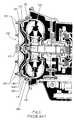
- FIG. 1is a longitudinal cross-section view of an ALLISON MT 600 torque converter assembly illustrating the internal components thereof and is labeled Prior Art;
- FIG. 2is a partial longitudinal cross-section view of the ALLISON MT 600 torque converter assembly and is labeled Prior Art;
- FIG. 3is an enlarged, partial longitudinal cross-section view of the ALLISON MT 600 torque converter assembly and is labeled Prior Art;
- FIG. 4is a top plan view of the replacement torque converter cover assembly of the present invention.
- FIG. 5is a longitudinal cross-section taken along section line 5 - 5 of FIG. 4 ;
- FIG. 6Ais an enlarged detail view showing a threaded stud of the present invention installed in the present replacement cover
- FIG. 6Bis an enlarged detail view showing a drive pin of the present invention installed in the present replacement cover.
- FIG. 7is a partial longitudinal cross-section of the present replacement cover showing a drive pin in engagement with the OEM lock-up piston.
- FIG. 1a cross-sectional view of such a torque converter assembly, indicated generally at 100 and illustrated in FIG. 1 , which is the primary component for transmittal of power between the engine and the automatic transmission in an automotive vehicle.
- the torque converter assembly 100provides for a smooth conversion of torque from the engine to the mechanical components of the automatic transmission and also functions to multiply torque from the engine enabling the vehicle to achieve additional performance when necessary.
- Torque converter assembly 100is comprised of the following main sub-assemblies: (1) an impeller assembly, indicated generally at 105 , which is the driving member; (2) a turbine assembly, indicated generally at 110 , which is the driven member; (3) a stator assembly, indicated generally at 115 , (4) a lock-up clutch assembly, indicated generally at 120 , which engages the turbine assembly 110 to enable direct mechanical drive; and (5) a front cover assembly (hereinafter “cover”), indicated generally at 125 , which is attached to the impeller assembly 105 as at 150 .
- coverfront cover assembly
- Cover 125is also attached to the engine flexplate (not shown) by threaded stud pins 140 that are mechanically attached to the engine flexplate so that the cover 125 will rotate at engine speed.
- Cover 125includes a cover pilot 127 on a forward-facing surface thereof to center the torque converter assembly 100 in coaxial relation to the engine crankshaft (not shown).
- the impeller assembly 105acts as a centrifugal pump by picking up ATF at its center and discharging it at its rim. The force of the ATF flow from the impeller assembly 105 is directed into the turbine assembly 110 and causes it to rotate. As the engine and impeller assembly 105 increase in speed, so does the turbine assembly 110 including turbine shaft 112 to mechanically operate the transmission.
- the lock-up clutch assembly 120includes a lock-up piston 142 having a plurality of pin receptacles 145 ( FIG. 2 ) formed within a forward facing surface thereof for engagement with the mating stud pins 140 extending through holes 126 which are drilled through the radial wall 125 a of cover 125 as most clearly shown in FIG. 3 .
- the lock-up clutch assembly 120also includes a circular friction plate 144 for frictional engagement with a concentrically disposed backing plate 146 .
- Lock-up piston 142is also mechanically attached to the turbine hub 111 ( FIG. 1 ).
- lock-up piston 142When lock-up is required the contact surface of lock-up piston 142 flexes axially rearward in response to increased ATF pressure within lock-up clutch 120 . Axial flexion of piston 142 is guided by pins 140 within mating receptacles 145 of piston 142 compressing friction plate 144 against backing plate 146 ( FIG. 1 ) to provide a direct mechanical coupling of the engine to the transmission during the torque converter lock-up cycle. When the lock-up clutch assembly 120 is applied, the slippage that occurs through the fluid coupling is eliminated providing a direct mechanical drive path from the engine to the transmission.
- a clutch apply chamber 170is formed between the cover 125 and the piston 142 .
- fluid pressure in the clutch apply chamber 170exceeds the spring preload force of the piston web 142 a , the contact surface of piston 142 is flexed axially rearward compressing the friction plate 144 between piston 142 and backing plate 146 ( FIG. 1 ) to initiate the lock-up cycle.
- a portopens that allows pressurized ATF to flow out of the clutch apply chamber 170 thereby releasing the lock-up piston 142 which is flexed in the reverse direction to end the lock-up cycle.
- the rotational torque force and mechanical stress imposed on the OEM cover 125 at engine idle and other peak torque eventsproduces stress fractures in the cover in proximity to holes 126 and adjacent to stud pins 140 , which are attached to cover 125 by weldment. Once a crack is initiated, the stress concentration effect becomes greater and the cracks progress more rapidly, which results in ATF leakage from the apply chamber 170 . As the stress increases in magnitude, that portion of the radial wall 125 a in proximity to holes 126 fails, which results in excessive ATF leakage and malfunction of the hydraulic system.
- FIGS. 4 and 5there is shown therein a replacement cover assembly in accordance with the present invention, indicated generally at 10 .
- the present replacement cover 10is machined from a high grade steel forging in accordance with American Iron and Steel Institute (AISI 1026) or other suitable material.
- AISI 1026American Iron and Steel Institute
- Replacement cover 10comprises a drum-shaped member having a radial wall 20 extending in generally perpendicular relation to the longitudinal axis -A- ( FIG. 5 ).
- An integral cylindrical portion 15 including flange 15 a of the cover 10extends axially from the radial wall 20 in concentric relation to axis -A-.
- the present cover 10includes a set of six threaded studs 40 installed in a concentric array at angular intervals of 60 degrees on a forward-facing surface of the cover ( FIG. 4 ).
- the present cover 10includes a set of six drive pins 45 also installed in a concentric array at angular intervals of sixty degrees on an opposite, rearward-facing surface of the cover 10 .
- both threaded studs 40 and drive pins 45are fabricated from high quality steel or other suitable material for this purpose.
- each threaded stud 40is installed in a mating threaded hole 42 as shown in FIG. 6A and after threaded engagement therein is permanently captured by weldment at the base of studs 40 . Thereafter, each remaining weld bead is ground flush with a forward-facing surface of radial wall 20 as at 35 ( FIG. 6A ).
- each drive pin 45is installed to an interference fit within a blind hole 46 formed on the inner surface of radial wall 20 of cover 10 to a predetermined depth corresponding to an axial stack-up length -L- ( FIG. 5 ) for threaded stud 40 and drive pin 45 assembled in cover 10 .
- the axial stack-up length -L-is equivalent to the overall length -OAL- ( FIG. 3 ) of OEM stud pins 145 .
- Such axial stack-up length -L-is critical for maintaining the functional position of the lock-up clutch assembly 120 during normal operation of the transmission.
- the axial length (i.e. thickness) -AL′- of the present radial wall 20has been substantially increased in comparison to the axial length (i.e. thickness) -AL- of the radial wall 125 a of the OEM cover 125 ( FIG. 3 ) to provide added structural strength and durability to the present replacement cover 10 .
Landscapes
- Engineering & Computer Science (AREA)
- General Engineering & Computer Science (AREA)
- Mechanical Engineering (AREA)
- General Details Of Gearings (AREA)
Abstract
Description
Claims (16)
Priority Applications (1)
| Application Number | Priority Date | Filing Date | Title |
|---|---|---|---|
| US11/893,330US7717244B2 (en) | 2006-08-15 | 2007-08-15 | Replacement torque converter cover assembly |
Applications Claiming Priority (2)
| Application Number | Priority Date | Filing Date | Title |
|---|---|---|---|
| US83776206P | 2006-08-15 | 2006-08-15 | |
| US11/893,330US7717244B2 (en) | 2006-08-15 | 2007-08-15 | Replacement torque converter cover assembly |
Publications (2)
| Publication Number | Publication Date |
|---|---|
| US20080041685A1 US20080041685A1 (en) | 2008-02-21 |
| US7717244B2true US7717244B2 (en) | 2010-05-18 |
Family
ID=39100318
Family Applications (1)
| Application Number | Title | Priority Date | Filing Date |
|---|---|---|---|
| US11/893,330Expired - Fee RelatedUS7717244B2 (en) | 2006-08-15 | 2007-08-15 | Replacement torque converter cover assembly |
Country Status (1)
| Country | Link |
|---|---|
| US (1) | US7717244B2 (en) |
Cited By (4)
| Publication number | Priority date | Publication date | Assignee | Title |
|---|---|---|---|---|
| US9163715B2 (en) | 2013-08-23 | 2015-10-20 | American Axle & Manufacturing, Inc. | Clutched power transmitting device with filter element |
| US9249873B2 (en) | 2013-08-23 | 2016-02-02 | American Axle & Manufacturing, Inc. | Power transmitting component with torque transfer device configured with drag reduction system |
| US9303696B2 (en) | 2013-08-23 | 2016-04-05 | American Axle & Manufacturing, Inc. | Optimized outer clutch housing for reduced spin loss, improved oil flow and improved clutch durability |
| US10458540B1 (en)* | 2017-01-03 | 2019-10-29 | Sonnax Transmission Company | Torque converters and methods and devices for rebuilding torque converters |
Families Citing this family (1)
| Publication number | Priority date | Publication date | Assignee | Title |
|---|---|---|---|---|
| US7770704B1 (en)* | 2007-05-04 | 2010-08-10 | Sonnax Industries, Inc. | Universal multiplate torque converter clutch system and method of use |
Citations (7)
| Publication number | Priority date | Publication date | Assignee | Title |
|---|---|---|---|---|
| US3338358A (en)* | 1955-12-22 | 1967-08-29 | Gen Motors Corp | Torque convertor with fluid operated lock-up clutch |
| US3734251A (en)* | 1971-11-18 | 1973-05-22 | Gen Motors Corp | Hydrodynamic unit with mechanical drive clutch |
| US6216837B1 (en)* | 1997-04-06 | 2001-04-17 | Luk Getriebe-Systeme Gmbh | Hydrokinetic torque converter |
| US6327766B1 (en)* | 1999-04-14 | 2001-12-11 | Portland Transmission Company, Inc. | Method for repairing studs fixed to a cover for a transmission torque connector |
| US20060016661A1 (en)* | 2004-07-22 | 2006-01-26 | Luk Lamellen Und Kupplungsbau Beteiligungs Kg | Device for operatively connecting an internal combustion engine to a transmission |
| US20060185955A1 (en)* | 2005-02-24 | 2006-08-24 | Exedy Corporation | Torque converter |
| US7296666B1 (en)* | 2005-06-29 | 2007-11-20 | Sonnax Industries, Inc. | Heavy-duty cover for torque converter |
Family Cites Families (3)
| Publication number | Priority date | Publication date | Assignee | Title |
|---|---|---|---|---|
| US6245026B1 (en)* | 1996-07-29 | 2001-06-12 | Farallon Medsystems, Inc. | Thermography catheter |
| US6514214B2 (en)* | 2001-02-13 | 2003-02-04 | Scimed Life Systems, Inc. | Intravascular temperature sensor |
| US6949072B2 (en)* | 2003-09-22 | 2005-09-27 | Infraredx, Inc. | Devices for vulnerable plaque detection |
- 2007
- 2007-08-15USUS11/893,330patent/US7717244B2/ennot_activeExpired - Fee Related
Patent Citations (7)
| Publication number | Priority date | Publication date | Assignee | Title |
|---|---|---|---|---|
| US3338358A (en)* | 1955-12-22 | 1967-08-29 | Gen Motors Corp | Torque convertor with fluid operated lock-up clutch |
| US3734251A (en)* | 1971-11-18 | 1973-05-22 | Gen Motors Corp | Hydrodynamic unit with mechanical drive clutch |
| US6216837B1 (en)* | 1997-04-06 | 2001-04-17 | Luk Getriebe-Systeme Gmbh | Hydrokinetic torque converter |
| US6327766B1 (en)* | 1999-04-14 | 2001-12-11 | Portland Transmission Company, Inc. | Method for repairing studs fixed to a cover for a transmission torque connector |
| US20060016661A1 (en)* | 2004-07-22 | 2006-01-26 | Luk Lamellen Und Kupplungsbau Beteiligungs Kg | Device for operatively connecting an internal combustion engine to a transmission |
| US20060185955A1 (en)* | 2005-02-24 | 2006-08-24 | Exedy Corporation | Torque converter |
| US7296666B1 (en)* | 2005-06-29 | 2007-11-20 | Sonnax Industries, Inc. | Heavy-duty cover for torque converter |
Cited By (7)
| Publication number | Priority date | Publication date | Assignee | Title |
|---|---|---|---|---|
| US9163715B2 (en) | 2013-08-23 | 2015-10-20 | American Axle & Manufacturing, Inc. | Clutched power transmitting device with filter element |
| US9249873B2 (en) | 2013-08-23 | 2016-02-02 | American Axle & Manufacturing, Inc. | Power transmitting component with torque transfer device configured with drag reduction system |
| US9303696B2 (en) | 2013-08-23 | 2016-04-05 | American Axle & Manufacturing, Inc. | Optimized outer clutch housing for reduced spin loss, improved oil flow and improved clutch durability |
| US10119576B2 (en) | 2013-08-23 | 2018-11-06 | American Axle & Manufacturing, Inc. | Optimized outer clutch housing for reduced spin loss, improved oil flow and improved clutch durability |
| US10458540B1 (en)* | 2017-01-03 | 2019-10-29 | Sonnax Transmission Company | Torque converters and methods and devices for rebuilding torque converters |
| US11009125B1 (en) | 2017-01-03 | 2021-05-18 | Sonnax Transmission Company | Torque converters and methods and devices for rebuilding torque converters |
| US11506281B2 (en) | 2017-01-03 | 2022-11-22 | Sonnax Transmission Company | Torque converters and methods and devices for rebuilding torque converters |
Also Published As
| Publication number | Publication date |
|---|---|
| US20080041685A1 (en) | 2008-02-21 |
Similar Documents
| Publication | Publication Date | Title |
|---|---|---|
| US9028201B2 (en) | Off axis pump with integrated chain and sprocket assembly | |
| US9243669B2 (en) | Torque converter flex plate for hybrid electric vehicle | |
| US7717244B2 (en) | Replacement torque converter cover assembly | |
| US9243672B2 (en) | Dual drive plate damper for hybrid electric vehicles | |
| US8465373B2 (en) | Face coupling | |
| CN101233315A (en) | Starting torque transmission mechanism of internal combustion engine | |
| JP2004003644A (en) | Hydraulic coupling device for automobile | |
| US7770704B1 (en) | Universal multiplate torque converter clutch system and method of use | |
| US7565958B1 (en) | Torque converter race kit | |
| US20100072014A1 (en) | Two piece impeller hub for hybrid torque converter | |
| JP4498385B2 (en) | Oil pump drive mechanism | |
| JP3978231B2 (en) | Hydrodynamic coupling device | |
| US5737836A (en) | Method of making a splined turbine hub | |
| US11421742B2 (en) | Torque converter connection on hybrid powertrain | |
| KR100602044B1 (en) | Fittings of automatic transmission | |
| JP2010078010A (en) | Power transmitting drive plate | |
| JP6328184B2 (en) | Transmission unit | |
| US20230114756A1 (en) | Generator module | |
| US10808819B2 (en) | Torque converter assembly and single face torque converter clutch | |
| KR20100089308A (en) | A carrier assembly for travel motor reducer in heavy construction equipment | |
| CN211423339U (en) | Combined sealing structure of hub reduction gear | |
| KR101323944B1 (en) | Engaging structure of a transmission output shaft and an input flange for forklift truck | |
| CN213017352U (en) | Flexible disc, power assembly and automobile | |
| US7296666B1 (en) | Heavy-duty cover for torque converter | |
| US20090013682A1 (en) | Torque converter with centered turbine |
Legal Events
| Date | Code | Title | Description |
|---|---|---|---|
| AS | Assignment | Owner name:SONNAX INDUSTRIES, INC., VERMONT Free format text:ASSIGNMENT OF ASSIGNORS INTEREST;ASSIGNOR:ROWELL, BRIAN G.;REEL/FRAME:019751/0826 Effective date:20070815 Owner name:SONNAX INDUSTRIES, INC.,VERMONT Free format text:ASSIGNMENT OF ASSIGNORS INTEREST;ASSIGNOR:ROWELL, BRIAN G.;REEL/FRAME:019751/0826 Effective date:20070815 | |
| STCF | Information on status: patent grant | Free format text:PATENTED CASE | |
| FPAY | Fee payment | Year of fee payment:4 | |
| FEPP | Fee payment procedure | Free format text:MAINTENANCE FEE REMINDER MAILED (ORIGINAL EVENT CODE: REM.) | |
| FEPP | Fee payment procedure | Free format text:7.5 YR SURCHARGE - LATE PMT W/IN 6 MO, LARGE ENTITY (ORIGINAL EVENT CODE: M1555) Free format text:ENTITY STATUS SET TO UNDISCOUNTED (ORIGINAL EVENT CODE: BIG.) | |
| MAFP | Maintenance fee payment | Free format text:PAYMENT OF MAINTENANCE FEE, 8TH YEAR, LARGE ENTITY (ORIGINAL EVENT CODE: M1552) Year of fee payment:8 | |
| AS | Assignment | Owner name:SONNAX TRANSMISSION COMPANY, VERMONT Free format text:ASSIGNMENT OF ASSIGNORS INTEREST;ASSIGNOR:SONNAX INDUSTRIES, INC.;REEL/FRAME:046625/0801 Effective date:20180330 | |
| FEPP | Fee payment procedure | Free format text:MAINTENANCE FEE REMINDER MAILED (ORIGINAL EVENT CODE: REM.); ENTITY STATUS OF PATENT OWNER: LARGE ENTITY | |
| LAPS | Lapse for failure to pay maintenance fees | Free format text:PATENT EXPIRED FOR FAILURE TO PAY MAINTENANCE FEES (ORIGINAL EVENT CODE: EXP.); ENTITY STATUS OF PATENT OWNER: LARGE ENTITY | |
| STCH | Information on status: patent discontinuation | Free format text:PATENT EXPIRED DUE TO NONPAYMENT OF MAINTENANCE FEES UNDER 37 CFR 1.362 | |
| FP | Lapsed due to failure to pay maintenance fee | Effective date:20220518 |