US7717115B2 - Delivery methods and devices for implantable bronchial isolation devices - Google Patents
Delivery methods and devices for implantable bronchial isolation devicesDownload PDFInfo
- Publication number
- US7717115B2 US7717115B2US10/723,273US72327303AUS7717115B2US 7717115 B2US7717115 B2US 7717115B2US 72327303 AUS72327303 AUS 72327303AUS 7717115 B2US7717115 B2US 7717115B2
- Authority
- US
- United States
- Prior art keywords
- bronchial
- outer shaft
- handle
- housing
- isolation device
- Prior art date
- Legal status (The legal status is an assumption and is not a legal conclusion. Google has not performed a legal analysis and makes no representation as to the accuracy of the status listed.)
- Active, expires
Links
- 238000002955isolationMethods0.000titleclaimsabstractdescription100
- 238000002716delivery methodMethods0.000titledescription2
- 210000004072lungAnatomy0.000claimsabstractdescription102
- 238000000034methodMethods0.000claimsdescription34
- 239000000463materialSubstances0.000claimsdescription10
- 230000007246mechanismEffects0.000claimsdescription8
- 230000008878couplingEffects0.000claimsdescription2
- 238000010168coupling processMethods0.000claimsdescription2
- 238000005859coupling reactionMethods0.000claimsdescription2
- 210000000621bronchiAnatomy0.000description21
- 210000001519tissueAnatomy0.000description19
- 210000003437tracheaAnatomy0.000description16
- 206010002091AnaesthesiaDiseases0.000description13
- 230000037005anaesthesiaEffects0.000description13
- 238000004513sizingMethods0.000description7
- 239000012530fluidSubstances0.000description5
- 210000001331noseAnatomy0.000description5
- 238000011282treatmentMethods0.000description5
- 206010014561EmphysemaDiseases0.000description4
- 239000007789gasSubstances0.000description4
- 230000002685pulmonary effectEffects0.000description4
- 230000029058respiratory gaseous exchangeEffects0.000description4
- 208000019693Lung diseaseDiseases0.000description3
- 230000001154acute effectEffects0.000description3
- 210000001124body fluidAnatomy0.000description3
- 239000010839body fluidSubstances0.000description3
- 230000007423decreaseEffects0.000description3
- 238000012800visualizationMethods0.000description3
- 239000004696Poly ether ether ketoneSubstances0.000description2
- 239000004642PolyimideSubstances0.000description2
- QVGXLLKOCUKJST-UHFFFAOYSA-Natomic oxygenChemical group[O]QVGXLLKOCUKJST-UHFFFAOYSA-N0.000description2
- 230000008901benefitEffects0.000description2
- UBAZGMLMVVQSCD-UHFFFAOYSA-Ncarbon dioxide;molecular oxygenChemical groupO=O.O=C=OUBAZGMLMVVQSCD-UHFFFAOYSA-N0.000description2
- 230000000881depressing effectEffects0.000description2
- 230000000994depressogenic effectEffects0.000description2
- 201000010099diseaseDiseases0.000description2
- 208000037265diseases, disorders, signs and symptomsDiseases0.000description2
- 230000000694effectsEffects0.000description2
- 239000007788liquidSubstances0.000description2
- 229910052760oxygenInorganic materials0.000description2
- 239000001301oxygenSubstances0.000description2
- 210000003281pleural cavityAnatomy0.000description2
- 229920002530polyetherether ketonePolymers0.000description2
- 229920001721polyimidePolymers0.000description2
- 229920000642polymerPolymers0.000description2
- 230000008569processEffects0.000description2
- 230000009467reductionEffects0.000description2
- 238000001356surgical procedureMethods0.000description2
- 210000003813thumbAnatomy0.000description2
- 229920002614Polyether block amidePolymers0.000description1
- 229910000831SteelInorganic materials0.000description1
- 239000004809TeflonSubstances0.000description1
- 229920006362Teflon®Polymers0.000description1
- 239000000853adhesiveSubstances0.000description1
- 230000001070adhesive effectEffects0.000description1
- 230000002411adverseEffects0.000description1
- 210000004712air sacAnatomy0.000description1
- 238000013459approachMethods0.000description1
- 238000001574biopsyMethods0.000description1
- 230000001684chronic effectEffects0.000description1
- 229920006018co-polyamidePolymers0.000description1
- 230000006835compressionEffects0.000description1
- 238000007906compressionMethods0.000description1
- 238000007796conventional methodMethods0.000description1
- 238000011038discontinuous diafiltration by volume reductionMethods0.000description1
- 210000004177elastic tissueAnatomy0.000description1
- 239000003000extruded plasticSubstances0.000description1
- 239000000835fiberSubstances0.000description1
- 210000003811fingerAnatomy0.000description1
- -1for exampleSubstances0.000description1
- 238000005286illuminationMethods0.000description1
- 238000003780insertionMethods0.000description1
- 230000037431insertionEffects0.000description1
- 230000003434inspiratory effectEffects0.000description1
- 210000003928nasal cavityAnatomy0.000description1
- HLXZNVUGXRDIFK-UHFFFAOYSA-Nnickel titaniumChemical compound[Ti].[Ti].[Ti].[Ti].[Ti].[Ti].[Ti].[Ti].[Ti].[Ti].[Ti].[Ni].[Ni].[Ni].[Ni].[Ni].[Ni].[Ni].[Ni].[Ni].[Ni].[Ni].[Ni].[Ni].[Ni]HLXZNVUGXRDIFK-UHFFFAOYSA-N0.000description1
- 229910001000nickel titaniumInorganic materials0.000description1
- 230000037361pathwayEffects0.000description1
- 230000000306recurrent effectEffects0.000description1
- 229920005989resinPolymers0.000description1
- 239000011347resinSubstances0.000description1
- 238000004904shorteningMethods0.000description1
- 239000010959steelSubstances0.000description1
- 238000012546transferMethods0.000description1
- 230000000472traumatic effectEffects0.000description1
- 230000002485urinary effectEffects0.000description1
Images


Classifications
- A—HUMAN NECESSITIES
- A61—MEDICAL OR VETERINARY SCIENCE; HYGIENE
- A61B—DIAGNOSIS; SURGERY; IDENTIFICATION
- A61B17/00—Surgical instruments, devices or methods
- A61B17/12—Surgical instruments, devices or methods for ligaturing or otherwise compressing tubular parts of the body, e.g. blood vessels or umbilical cord
- A61B17/12022—Occluding by internal devices, e.g. balloons or releasable wires
- A61B17/12099—Occluding by internal devices, e.g. balloons or releasable wires characterised by the location of the occluder
- A61B17/12104—Occluding by internal devices, e.g. balloons or releasable wires characterised by the location of the occluder in an air passage
- A—HUMAN NECESSITIES
- A61—MEDICAL OR VETERINARY SCIENCE; HYGIENE
- A61B—DIAGNOSIS; SURGERY; IDENTIFICATION
- A61B17/00—Surgical instruments, devices or methods
- A61B17/12—Surgical instruments, devices or methods for ligaturing or otherwise compressing tubular parts of the body, e.g. blood vessels or umbilical cord
- A61B17/12022—Occluding by internal devices, e.g. balloons or releasable wires
- A61B17/12131—Occluding by internal devices, e.g. balloons or releasable wires characterised by the type of occluding device
- A—HUMAN NECESSITIES
- A61—MEDICAL OR VETERINARY SCIENCE; HYGIENE
- A61B—DIAGNOSIS; SURGERY; IDENTIFICATION
- A61B17/00—Surgical instruments, devices or methods
- A61B17/12—Surgical instruments, devices or methods for ligaturing or otherwise compressing tubular parts of the body, e.g. blood vessels or umbilical cord
- A61B17/12022—Occluding by internal devices, e.g. balloons or releasable wires
- A61B2017/1205—Introduction devices
- A—HUMAN NECESSITIES
- A61—MEDICAL OR VETERINARY SCIENCE; HYGIENE
- A61B—DIAGNOSIS; SURGERY; IDENTIFICATION
- A61B17/00—Surgical instruments, devices or methods
- A61B17/24—Surgical instruments, devices or methods for use in the oral cavity, larynx, bronchial passages or nose; Tongue scrapers
- A61B2017/242—Surgical instruments, devices or methods for use in the oral cavity, larynx, bronchial passages or nose; Tongue scrapers for bronchial passages
- A—HUMAN NECESSITIES
- A61—MEDICAL OR VETERINARY SCIENCE; HYGIENE
- A61F—FILTERS IMPLANTABLE INTO BLOOD VESSELS; PROSTHESES; DEVICES PROVIDING PATENCY TO, OR PREVENTING COLLAPSING OF, TUBULAR STRUCTURES OF THE BODY, e.g. STENTS; ORTHOPAEDIC, NURSING OR CONTRACEPTIVE DEVICES; FOMENTATION; TREATMENT OR PROTECTION OF EYES OR EARS; BANDAGES, DRESSINGS OR ABSORBENT PADS; FIRST-AID KITS
- A61F2/00—Filters implantable into blood vessels; Prostheses, i.e. artificial substitutes or replacements for parts of the body; Appliances for connecting them with the body; Devices providing patency to, or preventing collapsing of, tubular structures of the body, e.g. stents
- A61F2/95—Instruments specially adapted for placement or removal of stents or stent-grafts
- A61F2/9517—Instruments specially adapted for placement or removal of stents or stent-grafts handle assemblies therefor
- A—HUMAN NECESSITIES
- A61—MEDICAL OR VETERINARY SCIENCE; HYGIENE
- A61F—FILTERS IMPLANTABLE INTO BLOOD VESSELS; PROSTHESES; DEVICES PROVIDING PATENCY TO, OR PREVENTING COLLAPSING OF, TUBULAR STRUCTURES OF THE BODY, e.g. STENTS; ORTHOPAEDIC, NURSING OR CONTRACEPTIVE DEVICES; FOMENTATION; TREATMENT OR PROTECTION OF EYES OR EARS; BANDAGES, DRESSINGS OR ABSORBENT PADS; FIRST-AID KITS
- A61F2/00—Filters implantable into blood vessels; Prostheses, i.e. artificial substitutes or replacements for parts of the body; Appliances for connecting them with the body; Devices providing patency to, or preventing collapsing of, tubular structures of the body, e.g. stents
- A61F2/02—Prostheses implantable into the body
- A61F2/04—Hollow or tubular parts of organs, e.g. bladders, tracheae, bronchi or bile ducts
- A61F2002/043—Bronchi
Definitions
- This inventionrelates generally to methods and devices for use in performing pulmonary procedures and, more particularly, to devices and procedures for treating lung diseases.
- Certain pulmonary diseasessuch as emphysema, reduce the ability of one or both lungs to fully expel air during the exhalation phase of the breathing cycle. Such diseases are accompanied by chronic or recurrent obstruction to air flow within the lung.
- One of the effects of such diseasesis that the diseased lung tissue is less elastic than healthy lung tissue, which is one factor that prevents full exhalation of air.
- the diseased portion of the lungdoes not fully recoil due to the diseased (e.g., emphysematic) lung tissue being less elastic than healthy tissue. Consequently, the diseased lung tissue exerts a relatively low driving force, which results in the diseased lung expelling less air volume than a healthy lung.
- the problemis further compounded by the diseased, less elastic tissue that surrounds the very narrow airways that lead to the alveoli, which are the air sacs where oxygen-carbon dioxide exchange occurs.
- the diseased tissuehas less tone than healthy tissue and is typically unable to maintain the narrow airways open until the end of the exhalation cycle. This traps air in the lungs and exacerbates the already-inefficient breathing cycle. The trapped air causes the tissue to become hyper-expanded and no longer able to effect efficient oxygen-carbon dioxide exchange.
- hyper-expanded, diseased lung tissueoccupies more of the pleural space than healthy lung tissue. In most cases, a portion of the lung is diseased while the remaining part is relatively healthy and, therefore, still able to efficiently carry out oxygen exchange.
- the hyper-expanded lung tissuereduces the amount of space available to accommodate the healthy, functioning lung tissue. As a result, the hyper-expanded lung tissue causes inefficient breathing due to its own reduced functionality and because it adversely affects the functionality of adjacent healthy tissue.
- Lung reduction surgeryis a conventional method of treating emphysema.
- a conventional surgical approachis relatively traumatic and invasive, and, like most surgical procedures, is not a viable option for all patients.
- Some recently proposed treatments for emphysema or other lung ailmentsinclude the use of devices that isolate a diseased region of the lung in order to modify the air flow to the targeted lung region or to achieve volume reduction or collapse of the targeted lung region.
- one or more bronchial isolation devicesare implanted in airways feeding the targeted region of the lung.
- the bronchial isolation deviceregulates fluid flow through the bronchial passageway in which the bronchial isolation device is implanted.
- the bronchial isolation devicescan be, for example, one-way valves that allow flow in the exhalation direction only, occluders or plugs that prevent flow in either direction, or two-way valves that control flow in both directions.
- the bronchial isolation devicecan be implanted in a target bronchial passageway using a delivery catheter that is placed through the trachea (via the mouth or the nasal cavities) and to the target location in the bronchial passageway. It would be advantageous to develop improved methods and devices for delivering bronchial isolation devices into the lung of a patient.
- an apparatus for deploying a bronchial isolation device in a bronchial passageway in a lung of a patientcomprising an outer shaft having a distal end; a housing coupled to the distal end of the outer shaft and configured to receive the bronchial device; an inner shaft slidably disposed within the outer shaft; and a handle adapted to move the outer shaft relative to both the inner shaft and the handle while the inner shaft remains fixed relative to the handle so as to eject the bronchial isolation device from the housing.
- an apparatus for deploying a bronchial isolation device in a bronchial passageway in a lung of a patientcomprising an outer shaft having a distal end; a housing coupled to the distal end of the outer shaft and configured to receive the bronchial device; an ejection member movably disposed in the housing; and a handle adapted to cause relative movement between the housing and the ejection member so as to eject the bronchial isolation device from the housing. Relative movement between the housing and the ejection member is limited to prevent the ejection member from moving substantially outside of the housing.
- an apparatus for delivering a device into a body passagewaycomprising a handle; an outer shaft movably coupled to the handle; an inner shaft slidably disposed within the outer shaft and fixedly coupled to the handle, the handle adapted to move the outer shaft relative to both the inner shaft and the handle while the inner shaft remains fixed relative to the handle; and a sheath attached to the handle and disposed over a portion of the outer shaft such that the outer shaft is free to slide within the sheath.
- Also disclosed is a method of deploying a bronchial device in a bronchial passageway in a patient's lungcomprising: providing a delivery device having an outer shaft, an inner shaft and a handle; coupling the bronchial isolation device to a housing on a distal end of the outer shaft and a inner shaft; advancing the delivery catheter into the patient's lung with the housing carrying the bronchial device until the housing is positioned in the bronchial passageway; and moving the outer shaft in a proximal direction relative to the inner shaft and the handle while the inner shaft remains fixed relative to the handle to release the bronchial isolation device from the housing.
- Also disclosed is a method of deploying a bronchial device in a bronchial passageway in a patient's lungcomprising providing a delivery device having an outer shaft, a housing coupled to a distal end of the outer shaft, and an ejection member movably disposed in the housing; advancing the delivery catheter into the patient's lung with the housing carrying the bronchial device until the housing is positioned in the bronchial passageway; and moving the ejection member relative to the housing to eject the bronchial isolation device from the housing, wherein the ejection member is substantially limited from moving outside of the housing.
- FIG. 1shows an anterior view of a pair of human lungs and a bronchial tree with a bronchial isolation device implanted in a bronchial passageway to bronchially isolate a region of the lung.
- FIG. 2illustrates an anterior view of a pair of human lungs and a bronchial tree.
- FIG. 3illustrates a lateral view of the right lung.
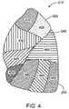
- FIG. 4illustrates a lateral view of the left lung.
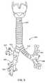
- FIG. 5illustrates an anterior view of the trachea and a portion of the bronchial tree.
- FIG. 6shows a perspective view of a bronchoscope.
- FIG. 7shows an enlarged view of a distal region of a bronchoscope.
- FIG. 8shows a delivery catheter for delivering a bronchial isolation device to a target location in a body passageway.
- FIG. 9shows a perspective view of a distal region of the delivery catheter.
- FIG. 10Ashows a plan, side view of the distal region of the delivery catheter.
- FIG. 10Bshows a cross-sectional view of the delivery catheter along line 10 B- 10 B of FIG. 10A .
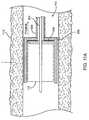
- FIG. 11Ashows the delivery catheter containing a bronchial isolation device in a housing, which is positioned at a location L of a bronchial passageway.
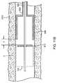
- FIG. 11Bshows the delivery catheter and the deployed bronchial isolation device at the location L of the bronchial passageway.
- FIG. 12shows a cross-sectional view of a delivery catheter deployed in a bronchial location that requires the delivery catheter's distal end to bend at an acute angle.
- FIG. 13shows a cross-sectional view of the distal end of the delivery catheter with a limited-travel flange fully retracted into the delivery housing.
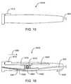
- FIG. 14shows a cross-sectional view of the distal end of the delivery catheter with a limited-travel flange fully extended.
- FIG. 15shows a side view of one embodiment of an actuation handle of the delivery catheter.
- FIG. 16shows a cross-sectional, side view of the actuation handle of FIG. 15 with an actuation member in an initial position.
- FIG. 17shows a cross-sectional, side view of a portion of the actuation handle of FIG. 15 with the actuation member distal of the initial position.
- FIG. 18shows an enlarged view of the distal region of the bronchoscope with the delivery catheter's distal end protruding outward from the working channel.
- FIG. 19shows another embodiment of the delivery catheter handle configured for transcopic delivery.
- FIG. 20shows the delivery catheter of FIG. 19 positioned within the working channel of the bronchoscope with the catheter handle protruding from the bronchoscope.
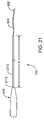
- FIG. 21shows an embodiment of the delivery catheter that includes a deployment sheath.
- FIG. 22shows a partial view of the delivery catheter of FIG. 21 positioned through an anesthesia adapter.
- bronchial isolation deviceswhich are sometimes referred to herein as flow control devices
- the bronchial isolation deviceis delivered to a target location in the bronchial passageway by mounting the bronchial isolation device in a housing at the distal end of a delivery catheter and then inserting the delivery catheter into the bronchial passageway. Once the housing is positioned at a target location in the bronchial passageway, the bronchial isolation device is ejected from the housing and deployed within the passageway. In the example shown in FIG.
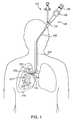
- FIG. 1the distal end of the delivery catheter 110 is inserted into the patient's mouth or nose, through the trachea, and down to a target location in the bronchial passageway 517 .
- FIG. 1does not show the housing in which the device is contained.
- lung regionrefers to a defined division or portion of a lung.
- lung regionsare described herein with reference to human lungs, wherein some exemplary lung regions include lung lobes and lung segments.
- the term “lung region” as used hereincan refer, for example, to a lung lobe or a lung segment. Such nomenclature conform to nomenclature for portions of the lungs that are known to those skilled in the art.
- the term “lung region”does not necessarily refer to a lung lobe or a lung segment, but can refer to some other defined division or portion of a human or non-human lung.
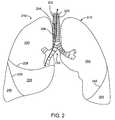
- FIG. 2shows an anterior view of a pair of human lungs 210 , 215 and a bronchial tree 220 that provides a fluid pathway into and out of the lungs 210 , 215 from a trachea 225 , as will be known to those skilled in the art.
- the term “fluid”can refer to a gas, a liquid, or a combination of gas(es) and liquid(s).
- FIG. 2shows only a portion of the bronchial tree 220 , which is described in more detail below with reference to FIG. 5 .
- FIG. 2shows a path 202 that travels through the trachea 225 and through a bronchial passageway into a location in the right lung 210 .
- proximal directionrefers to the direction along such a path 202 that points toward the patient's mouth or nose and away from the patient's lungs.
- the proximal directionis generally the same as the expiration direction when the patient breathes.
- the arrow 204 in FIG. 2points in the proximal or expiratory direction.
- the term “distal direction”refers to the direction along such a path 202 that points toward the patient's lung and away from the mouth or nose.
- the distal directionis generally the same as the inhalation or inspiratory direction when the patient breathes.
- the arrow 206 in FIG. 2points in the distal or inhalation direction.
- the lungsinclude a right lung 210 and a left lung 215 .
- the right lung 210includes lung regions comprised of three lobes, including a right upper lobe 230 , a right middle lobe 235 , and a right lower lobe 240 .
- the lobes 230 , 235 , 240are separated by two interlobar fissures, including a right oblique fissure 226 and a right transverse fissure 228 .
- the right oblique fissure 226separates the right lower lobe 240 from the right upper lobe 230 and from the right middle lobe 235 .
- the right transverse fissure 228separates the right upper lobe 230 from the right middle lobe 235 .
- the left lung 215includes lung regions comprised of two lobes, including the left upper lobe 250 and the left lower lobe 255 .
- An interlobar fissure comprised of a left oblique fissure 245 of the left lung 215separates the left upper lobe 250 from the left lower lobe 255 .
- the lobes 230 , 235 , 240 , 250 , 255are directly supplied air via respective lobar bronchi, as described in detail below.
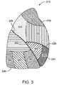
- FIG. 3is a lateral view of the right lung 210 .
- the right lung 210is subdivided into lung regions comprised of a plurality of bronchopulmonary segments. Each bronchopulmonary segment is directly supplied air by a corresponding segmental tertiary bronchus, as described below.
- the bronchopulmonary segments of the right lung 210include a right apical segment 310 , a right posterior segment 320 , and a right anterior segment 330 , all of which are disposed in the right upper lobe 230 .
- the right lung bronchopulmonary segmentsfurther include a right lateral segment 340 and a right medial segment 350 , which are disposed in the right middle lobe 235 .
- the right lower lobe 240includes bronchopulmonary segments comprised of a right superior segment 360 , a right medial basal segment (which cannot be seen from the lateral view and is not shown in FIG. 3 ), a right anterior basal segment 380 , a right lateral basal segment 390 , and a right posterior basal segment 395 .
- FIG. 4shows a lateral view of the left lung 215 , which is subdivided into lung regions comprised of a plurality of bronchopulmonary segments.
- the bronchopulmonary segmentsinclude a left apical segment 410 , a left posterior segment 420 , a left anterior segment 430 , a left superior segment 440 , and a left inferior segment 450 , which are disposed in the left lung upper lobe 250 .
- the lower lobe 255 of the left lung 215includes bronchopulmonary segments comprised of a left superior segment 460 , a left medial basal segment (which cannot be seen from the lateral view and is not shown in FIG. 4 ), a left anterior basal segment 480 , a left lateral basal segment 490 , and a left posterior basal segment 495 .
- FIG. 5shows an anterior view of the trachea 325 and a portion of the bronchial tree 220 , which includes a network of bronchial passageways, as described below.
- the trachea 225divides at a lower end into two bronchial passageways comprised of primary bronchi, including a right primary bronchus 510 that provides direct air flow to the right lung 210 , and a left primary bronchus 515 that provides direct air flow to the left lung 215 .
- Each primary bronchus 510 , 515divides into a next generation of bronchial passageways comprised of a plurality of lobar bronchi.
- the right primary bronchus 510divides into a right upper lobar bronchus 517 , a right middle lobar bronchus 520 , and a right lower lobar bronchus 422 .
- the left primary bronchus 415divides into a left upper lobar bronchus 525 and a left lower lobar bronchus 530 .
- Each lobar bronchus 517 , 520 , 522 , 525 , 530directly feeds fluid to a respective lung lobe, as indicated by the respective names of the lobar bronchi.
- the lobar bronchieach divide into yet another generation of bronchial passageways comprised of segmental bronchi, which provide air flow to the bronchopulmonary segments discussed above.
- a bronchial passagewaydefines an internal lumen through which fluid can flow to and from a lung or lung region.
- the diameter of the internal lumen for a specific bronchial passagewaycan vary based on the bronchial passageway's location in the bronchial tree (such as whether the bronchial passageway is a lobar bronchus or a segmental bronchus) and can also vary from patient to patient.
- the internal diameter of a bronchial passagewayis generally in the range of 3 millimeters (mm) to 10 mm, although the internal diameter of a bronchial passageway can be outside of this range.
- a bronchial passagewaycan have an internal diameter of well below 1 mm at locations deep within the lung.
- the internal diametercan also vary from inhalation to exhalation as the diameter increases during inhalation as the lungs expand, and decreases during exhalation as the lungs contract.
- the bronchial isolation deviceis deployed in the bronchial passageway using a delivery catheter 110 , which is inserted into the bronchial passageway through the patient's trachea.
- the delivery catheter 110is inserted directly into the trachea and bronchial passageway.
- a bronchoscope 120assists in the insertion of the delivery catheter 110 through the trachea and into the bronchial passageway.
- the method that uses the bronchoscope 120is referred to as the “transcopic” method.
- the delivery catheter 110is inserted into the working channel of the bronchoscope 120 , which is deployed to the bronchial passageway 517 either before or after the delivery catheter has been inserted into the bronchoscope 120 .
- the bronchoscope 120has a steering mechanism 125 , a delivery shaft 130 , a working channel entry port 135 , and a visualization eyepiece 140 .
- FIG. 1shows the bronchoscope 120 positioned with its distal end at the right primary bronchus 510 .
- the delivery catheter 110is positioned within the bronchoscope 120 such that the delivery catheter's distal end and the attached bronchial isolation device 115 protrude outward from the distal end of the bronchoscope 120 , as shown in FIG. 1 .
- FIG. 6shows an enlarged view of the bronchoscope 120 , including the steering mechanism 125 , delivery shaft 130 , working channel entry port 135 , and visualization eyepiece 140 .
- the bronchoscopecan also include a fiber optic bundle mounted inside the length of the bronchoscope for transferring an image from the distal end to the eyepiece 140 .
- the bronchoscopealso includes a camera or charge-coupled device (CCD) for generating an image of the bronchial tree.
- FIG. 7shows an enlarged view of the distal portion of the bronchoscope 120 .
- a working channel 710(sometimes referred to as a biopsy channel) extends through the delivery shaft 130 and communicates with the entry port 135 (shown in FIG.
- the working channel 710can sometimes be formed by an extruded plastic tube inside the body of the bronchoscope 120 .
- the bronchoscope 120can also include various other channels, such as a visualization channel 720 that communicates with the eyepiece 140 and one or more illumination channels 730 .
- the bronchoscopecan have a variety of configurations and is not limited to the embodiment shown in the figures.
- the working channel 710may be formed of a flexible material and temporarily or permanently attached to the outside of the delivery shaft 130 .
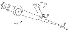
- FIG. 8shows one embodiment of the delivery catheter 110 for delivering and deploying the bronchial isolation device 115 to a target location in a bronchial passageway.
- the delivery catheter 110has a proximal end 810 and a distal end 815 that can be deployed to a target location in a patient's bronchial passageway, such as through the trachea.
- the catheter 110has an elongated outer shaft 820 and an elongated inner shaft 825 that is slidably positioned within the outer shaft 820 such that the outer shaft 820 can slidably move relative to the inner shaft 825 along the length of the catheter, as described in more detail below.
- an actuation handle 830is located at the proximal end 810 of the catheter 110 .
- the actuation handle 830can be actuated to slidably move the outer shaft 820 in a proximal direction relative to the inner shaft 825 with the inner shaft 825 remaining fixed relative to the actuation handle 830 . During such movement, the outer shaft 820 slides over the inner shaft 825 .
- FIG. 8shows a schematic view of the actuation handle 830 , which is described in more detail below.
- the handle 830includes a first piece 835 and a second actuation piece 840 , which is moveable relative to the first piece 835 .
- the outer shaft 820 of the catheter 110can be moved relative to the inner shaft 825 by moving the first piece 835 of the handle 830 relative to the second piece 840 .
- the inner shaft 825 of the catheter 110can include a central guidewire lumen (not shown) that extends through the entire length of the catheter 110 .
- the central guidewire lumen of the inner shaft 825is sized to receive a guidewire, which can be used during deployment of the catheter 110 to guide the catheter 110 to a location in a bronchial passageway.
- a housing 850is located at or near a distal end of the catheter 110 for holding therein the bronchial isolation device 115 .
- the housing 850is attached to a distal end of the outer shaft 820 of the catheter 110 but not attached to the inner shaft 825 , which extends axially through the housing.
- the housing 850defines an inner cavity that is sized to receive the bronchial isolation device 115 therein.
- FIG. 9shows an enlarged, perspective view of the distal portion of the catheter 110 where the housing 850 is located.
- FIG. 10Ashows a plan, side view of the distal portion of the catheter 110 where the housing 850 is located.
- the housing 850is shaped to receive the bronchial isolation device therein and is open at a distal end and closed at a proximal end.
- the inner shaft 825 of the catheter 110protrudes through the housing 850 and can slidably move relative to the housing 850 .
- An ejection member, such as a flange 910is attached at or near a distal end of the inner shaft 825 .
- the flange 910is sized such that it can be received into the housing 850 so that the flange 910 can be withdrawn into the housing 850 to abut a proximal end of the housing.
- FIGS. 9 and 10Ashow the flange 910 positioned outside of the housing 850 .
- the ejection membercan be used to eject the bronchial isolation device 115 from the housing 850 .
- the housingcan be manufactured of a rigid material, such as steel.
- the housing 850can also be flexible or collapsible. Although the housing 850 is shown having a cylindrical shape, it should be appreciated that the housing 850 can have other shapes that are configured to receive the bronchial isolation device therein.
- a sizing element 925is located at or near the housing 850 , as shown in FIGS. 10A and 10B . (For clarity of illustration, FIG. 10B does not show the bronchial isolation device 115 mounted in the housing 850 and does not show the inner shaft 825 of the delivery catheter.)
- the sizing element 925can be used to determine whether the bronchial isolation device 115 in the housing 850 will fit within a particular bronchial passageway in a working manner.
- the sizing element 925comprises one or more extensions, such as first extensions 930 a and second extensions 930 b that define distances L 1 and L 2 , respectively.
- the opposed, outer tips of the extensions 930 aare separated by a distance L 1 and the opposed, outer tips of the extensions 930 b are separated by a distance L 2 .
- the distance L 1corresponds to the diameter of the larger end of the functional diameter range of the bronchial isolation device 115 . That is, the distance L 1 is substantially equal to the largest possible diameter for a bronchial passageway in which the bronchial isolation device can be functionally deployed.
- the distance L 2corresponds to the diameter of the lower end of the functional diameter range of the bronchial isolation device 115 . That is, the distance L 2 is substantially equal to the smallest possible diameter for a bronchial passageway in which the bronchial isolation device 115 can be functionally deployed.
- the extensions 930can take on a variety of structures and shapes. For example, FIGS. 10A and 10B shows the extensions 930 comprising elongate prongs that extend radially outward from the catheter or the housing 850 .
- the extensions 930 of the sizing element 925comprise two or more loops 931 a and 931 b , which correspond to the extensions 930 a and 930 b , respectively.
- Each loop 931forms an ellipse having a long axis of a predetermined length.
- the loop 931 ahas a long axis of length L 1 that is greater than the length L 2 of the long axis of the second loop 931 b .
- the larger length L 1 of loop 931 acorresponds to the diameter of the larger end of the functional diameter range of the bronchial isolation device 115 .
- the shorter length L 2 of loop 931 bcorresponds to the diameter of the lower end of the functional diameter range of the bronchial isolation device.
- the sizing element 925is used to determine whether or not the bronchial passageway is within the functional range of the bronchial isolation device 115 .
- the opposed tips of the longer extensions 930 ae.g., the diameter loop 931 a
- the bronchial isolation device 115is too small to be implanted in that passageway.
- the bronchial passagewayis too large for the bronchial isolation device if the tips of the longer extensions 930 a cannot simultaneously contact the bronchial wall when the extensions 930 a are centrally positioned within the bronchial passageway. If the opposed tips of the shorter extensions 930 b can simultaneously contact the wall of the bronchial passageway, then the bronchial isolation device 115 is too large to be implanted in the bronchial passageway in a working manner.
- the extensions 930can be constructed of various materials.
- the extensionsare constructed of wire, etched from a flat plate, or by other methods.
- the extensions 930can be made of a flexible material, such as Nitinol, or a polymer or other flexible material, such that the extensions fold down when inserted into or retracted into the working channel of the bronchoscope.
- the extensionsare manufactured of Pebax, which is a polyether-block co-polyamide polymer. Other flexible resins can be used as well.
- Other configurations and shapes of the sizing element 925are contemplated, such as standing struts rather than loops, etc.
- the bronchial isolation device 115is first inserted into the housing 850 .
- the bronchial isolation device 115can be inserted into the housing according to various methods and devices, some of which are described in U.S. patent application Ser. No. 10/270,792, entitled “Bronchial Flow Control Devices and Methods of Use”, which is assigned to Emphasys Medical, Inc., the assignee of the instant application.
- the distal end of the delivery catheter 110is deployed into a bronchial passageway via the trachea such that the housing 850 is located at or near the target location in the bronchial passageway, as shown in FIG. 11A .
- an operatorcan eject the bronchial isolation device 115 from the housing 850 into the bronchial passageway.
- FIG. 11Ashows a cross-sectional view of a bronchial passageway 1110 with the deliver catheter 110 positioned therein.
- the distal end of the delivery catheter 110including the housing 850 , is located at or near the target location L.
- an operatoractuates the catheter handle 830 to slidably move the outer catheter member 820 in a proximal direction relative to the location L, while maintaining the location of the bronchial isolation device 115 , inner shaft 825 , and flange 910 fixed with respect to the location L.
- the proximal movement of the outer shaft 820causes the attached housing 850 to also move in a proximal direction, while the flange 910 prevents the bronchial isolation device 115 from moving in the proximal direction. This results in the housing 850 sliding away from engagement with the bronchial isolation device 115 so that the bronchial isolation device 115 is eventually entirely released from the housing 850 and implanted in the bronchial passageway at the target location L, as shown in FIG. 11B .
- the outer shaft 820can undergo tension and the inner shaft 825 undergo compression due to the relative movement of the shafts and possible friction against the proximal movement of the outer shaft 820 . This can result in an axial shortening of the inner shaft 825 and an axial lengthening of the outer shaft 820 .
- the flange 910can be configured to over-travel a distance Y beyond the distal end of the housing 850 , as shown in FIG. 11B .
- FIG. 12shows such a situation, where the bronchial isolation device 115 is deployed at a location in the bronchial tree 220 that requires the delivery catheter 110 to bend at an acute angle with the flange 910 withdrawn entirely from the housing 850 .
- the flange 910can catch on the tissue of the bronchial wall at a location 1210 inside the bend as the operator pulls the catheter 110 out of the bronchial passageway. This can make it difficult for an operator to remove the delivery catheter 110 from the bronchial passageway and can risk possible damage to the tissue if the operator continues to pull while the flange is caught on the bend.
- FIG. 13shows a cross-sectional view of the distal region of the catheter, showing the inner shaft 825 axially disposed in the outer shaft 820 .
- the flange 910is attached to the inner shaft 825 and the housing 850 is attached to the outer shaft 820 .
- the inner shaft 825has a step 1405 and the housing 850 or outer shaft 820 has a stop or ledge 1410 .
- the step 1405is spaced from the ledge 1410 when the flange 910 is fully withdrawn in the housing 850 .
- the step 1405eventually abuts the ledge 1410 , which acts as a stop to limit any further proximal movement of the outer shaft 820 relative to the inner shaft 825 .
- the flange 910is positioned just at the distal end of the housing 850 when the stop position is reached. Thus, the flange 910 and housing 850 have a relative range of travel therebetween.
- the flange 910is limited from being distally positioned at all past a distal edge of the housing. In another embodiment, the flange 910 can be distally positioned past the distal end of the housing only to the extent that the flange will not catch onto tissue during withdrawal of the delivery catheter.
- the distance Yis sufficiently small to prevent or greatly reduce the likelihood of bronchial wall tissue being caught or pinched between the flange 910 and the housing 850 during withdrawal of the delivery catheter 110 . This eliminates the possibility of the flange 910 catching or lodging on the bronchial tissue during removal of the delivery catheter 110 .
- FIG. 15shows a side view of an actuation handle 1510 .
- the actuation handle 1510has an elongate shape suitable for grasping within an operator's hand. It should be appreciated, however, that the shape of the actuation handle 1510 can vary.
- the actuation handle 1510includes an actuation member, such as a slidable actuation slider 1515 , that can be actuated to slide the outer shaft 820 relative to the inner shaft 825 (the inner shaft is not shown in FIG.
- the actuation membercan be positioned on the handle 1510 such that an operator can grasp the handle with a single hand and also move the actuation member using a finger or thumb of the same hand.
- the slider 1515is positioned along the side of the actuation handle 1510 so that the operator's thumb can be used to move the slider 1515 .
- Other configurationscan be used.
- FIG. 16shows a cross-sectional view of the actuation handle 1510 , which includes an actuation system for moving the outer shaft relative to the handle.
- the actuation systemcomprises a rack and pinion system for effecting movement of the outer shaft 820 relative to the inner shaft 825 .
- the actuation slider 1515is coupled to the actuation system.
- the actuation slider 1515is slidably positioned inside an elongate slot 1605 in the actuation handle 1510 .
- a distal end of the actuation slider 1515abuts or is attached to a first rack 1610 that is also slidably mounted in the elongate slot 1605 .
- the first rack 1610has a first edge with teeth that mesh with corresponding teeth on a first pinion 1615 .
- the first pinion 1615is engaged with a second pinion 1620 having teeth that mesh with a second rack 1625 mounted in an elongate slot 1628 .
- the second rack 1625is attached to the outer shaft 820 of the delivery catheter 110 such that movement of the second rack 1625 corresponds to movement of the outer shaft 820 . That is, when the second rack slidably moves in the proximal direction or distal direction, the outer shaft 820 also moves in the proximal or distal direction, respectively.
- the inner shaft 825is fixedly attached to the handle 1510 , such as by using adhesive or through a friction fit.
- the first rack, second rack, first pinion, and second pinioncollectively form a rack and pinion system that can be used to transfer distal movement of the actuation slider 1515 to proximal movement of the outer shaft 820 while the inner shaft 825 remains stationary relative to the handle 1510 , as described below.
- the actuation slider 1515can be positioned in an initial position, as shown in FIG. 16 .
- the actuation slider 1515is in the initial position, the flange 910 is fully withdrawn inside the housing 950 (as shown in FIG. 13 ).
- the actuation slider 1515is at the proximal end of the handle when in the initial position, although it should be appreciated that the initial position can vary.
- the rack and pinion systemcauses the outer shaft 820 to slidably move in the proximal direction (represented by the arrow 1635 in FIG.
- the inner catheter 825(which is fixed to the handle 1510 ) remains stationary relative to the handle 1510 while the outer shaft 820 moves.
- the outer shaft 820(and the attached housing 850 ) slides in the proximal direction, with the inner shaft 820 and flange 910 remaining stationary relative to the handle.
- the handlecan be fixed relative to the patient such that the handle, inner shaft, flange and bronchial isolation device remain fixed relative to the patient during ejection of the bronchial isolation device from the housing.
- the gear ratio between the first pinion 1615 and second pinion 1620can be varied to result in a desired ratio of movement between the actuation slider 1515 and the outer catheter 820 .
- the first pinion 1615can have a larger diameter than the second pinion 1620 so that the outer shaft 820 (and the attached housing 850 ) are withdrawn in the proximal direction at a slower rate than the actuation slider 1515 is advanced in the distal direction.
- the gear ratiocan also be varied to reduce the force required to move the actuation slider 1515 and thereby make it easier for an operator to control ejection of the bronchial isolation device 115 from the housing 850 .
- the ratio between the pinionscan be altered to make the withdrawal of the outer shaft faster, slower, or the same speed as the actuation slider movement.
- the rack and pinion systemis configured such that a 2:1 force reduction occurs such that the actuator slider moves about twice the distance that the outer shaft 820 is moved. For example, if the slider is moved an inch in the distal direction, then the outer shaft and the attached housing moves about half an inch in the proximal direction, and vice-versa.
- the handle 1510can include a safety lock that retains the actuation slider 1515 (or any other type of actuation member) in the initial position until the operator applies a force to the actuation slider sufficient to disengage the safety lock.
- the safety lockprevents inadvertent deployment of the bronchial isolation device either by inadvertent movement of the actuation slider in the distal direction or by inadvertent movement of the outer shaft 820 in the proximal direction relative to the handle. Inadvertent proximal movement of the outer shaft 820 can possibly occur when the delivery catheter 110 is being advanced into the patient's trachea, which can cause resistance to be applied to the outer shaft 820 by an anesthesia adaptor valve, endotracheal tube, or the lung.
- the safety lockcomprises one or more magnets positioned in the actuation handle 1510 .
- FIG. 17shows a partial, cross-sectional view of the proximal end of the handle 1510 with the actuation slider 1515 positioned distally of the initial position.
- a first magnet 1710is located on the handle 1510 near the initial location of the actuation slider 1515 .
- a second magnet 1715is located on or in the actuation slider 1515 .
- the magnets 1710 , 1715are oriented such that an attractive magnetic force exists therebetween.
- the magnetic force between the magnets 1710 , 1715retains the actuation slider 1515 in the initial position until the operator applies a force to the slider 1515 sufficient to overcome the magnetic force and move the slider 1515 out of the initial position.
- magnets 1710 , 1715can be employed as the safety lock.
- One advantage of magnetsis that the attractive force between the magnets 1710 , 1715 automatically increases as the actuation slider moves toward the initial position. If the actuation slider happens to be out of the initial position when the bronchial isolation device is loaded into the housing 850 , the actuation slider 1515 is driven back toward the initial position as the bronchial isolation device is loaded into the housing 850 . The magnetic attraction between the first and second magnets 1710 , 1715 automatically engages the safety lock when the actuation slider 1515 moves into the initial position.
- the safety lockcan include an additional feature wherein the operator must depress the actuation slider 1515 in order to disengage the slider from the initial position.
- the slot 1605 in the actuation handle 1510has an opening 1712 .
- the actuation slider 1515moves outward and sits in the opening 1712 when in the initial position. The operator must depress the slider 1515 to move the actuation slider 1515 out of the opening in order to disengage the slider from the initial position and slide the actuation slider 1515 in the distal direction.
- the bronchoscope 120(shown in FIGS. 1 , 6 , 7 ) is used in deploying the delivery catheter 110 into the bronchial passageway.
- the delivery catheter 110is inserted into the working channel 710 of the bronchoscope 120 such that the delivery catheter's distal end is aligned with or protrudes from the distal end of the bronchoscope 120 .
- the bronchoscope 120with the delivery catheter 110 positioned as such, is then inserted into the bronchial passageway via the patient's trachea such that the distal end of the delivery catheter is positioned at a desired location in the bronchial passageway, as shown in FIG. 1 .
- the delivery catheter 110can be inserted into the bronchoscope 120 either before or after the bronchoscope has been inserted into the bronchial passageway.
- FIG. 18shows an enlarged view of the distal region of the bronchoscope 120 with the delivery catheter's distal end (including the housing 850 ) protruding outward from the working channel 710 .
- the bronchial isolation device 115is positioned within the housing 850 .
- the bronchial isolation device 115is a distance D from the distal end of the bronchoscope 120 .
- the operatormay desire to adjust the distance D to fine tune the location of the bronchial isolation device 115 .
- FIG. 19shows another embodiment of the actuation handle, referred to as actuation handle 1910 , that can be used for transcopic delivery and that can be fixed relative to a bronchoscope while also allowing for adjustments in the distance D of FIG. 18 once the delivery device is positioned in the bronchoscope.
- the actuation handle 1910includes an actuation member in the form of a button 1915 that can be depressed in the distal direction to move the outer shaft 820 of the delivery catheter in the proximal direction.
- the handleincludes an adjustment mechanism that is used to adjust the position of the handle relative to the bronchoscope.
- the adjustment mechanismcomprises an elongated bronchoscope mount 1920 that extends outwardly from the distal end of the actuation handle 1910 and extends at least partially over the catheter outer shaft 820 such that the outer shaft can slide freely within the bronchoscope mount 1920 .
- the bronchoscope mount 1920extends outward from the handle a distance A.
- the bronchoscope mount 1920is slidably moveable into or out of the handle 1910 such that it can be pushed into or pulled out of the handle 1910 along the axis of the mount 1920 in order to adjust the distance A.
- the bronchoscope mount 1920is biased outward, for example with a spring, so that its tendency is to be fully extended outward from the handle 1910 .
- a locking mechanismincludes a lock, such as a lever 1925 , that can be depressed to lock the bronchoscope mount 1920 relative to the handle 1910 when the distance A is adjusted to a desired amount, as described below. Once the distance A is at a desired amount, the operator can lock the bronchoscope mount 1920 relative to the handle to fix the bronchoscope mount 1920 relative to the handle 1910 .
- a locksuch as a lever 1925
- the bronchoscope mount 1920has a size and shape that is configured to sit within the entry port 135 of the bronchoscope working channel.
- an operatorcan insert the bronchoscope mount 1920 into the entry port 135 such that it abuts and sits within the entry port 135 .
- the actuation handle 1910is fixed relative to the bronchoscope 120 with the catheter's distal end protruding a distance D from the bronchoscope's distal end (as shown in FIG. 20 ).
- the operatorcan then adjust the distance A by moving the bronchoscope mount 1920 into or out of the handle 1910 , such as by pushing on the handle 1910 to decrease the distance A.
- the bronchoscope mount 1920is locked by depressing the lever 1925 .
- the operatoralso adjusts the distance D (shown in FIG. 18 ) between the distal end of the bronchoscope 120 and the bronchial isolation device 115 . This can be helpful where different brands or types of bronchoscopes have different length working channels. It also allows the operator to fine-tune the position of the housing 850 and bronchial isolation device in the bronchial passageway without moving the bronchoscope.
- bronchoscope mount 1920Other mechanisms for locking the movement of the bronchoscope mount 1920 are possible such as depressing and holding the lever 1925 to release the movement of the bronchoscope mount 1920 , repositioning the bronchoscope mount 1920 , and releasing the lever 1925 to lock the bronchoscope mount 1920 in place.
- the delivery catheter 110it can be desirable to fix the location of the inner shaft 825 (and thus the bronchial isolation device in the housing 850 ) relative to the patient's body while proximally withdrawing the outer shaft 820 and the housing 850 relative to the bronchial passageway to eject the bronchial isolation device, as shown in FIGS. 11A and 11B .
- the outer shaft 820moves proximally relative to the bronchial passageway during the foregoing process, the outer shaft 820 can encounter resistance to proximal movement due to friction with devices or body passageways in which the delivery device is positioned.
- the outer surface of the outer shaft 820can encounter frictional resistance against an anesthesia adaptor through which the outer shaft is inserted.
- the anesthesia adapteris a fitting that permits the bronchoscope and delivery catheter to be inserted into the lung without leakage of ventilated oxygen, anesthesia gases, or other airway gases.
- the adaptertypically has a valve through which the delivery catheter or bronchoscope is inserted.
- the valveseals against the outer surface of the outer shaft 820 to prevent air leaks. This seal can provide resistance against proximal movement of the outer shaft 820 during ejection of the bronchial isolation device from the housing 850 .
- Such resistance to proximal movement of the outer shaft 820is undesirable, as it can result in the bronchial isolation device 115 being deployed in a location distal of the target location in the bronchial passageway.
- FIG. 21shows an embodiment of the delivery catheter 110 , which includes a deployment sheath 2110 that reduces or eliminates the resistance to proximal movement of the catheter outer shaft 820 during ejection of the bronchial isolation device 115 .
- the deployment sheath 2110is a sheath having an internal lumen in which the outer shaft 820 is slidably positioned.
- the sheath 2110is fixed at a proximal end 2112 to the actuation handle 815 .
- FIG. 21shows the actuation handle 815 , although the sheath 2110 can be used with any type of handle.
- the sheath 2110is not limited to use with delivery catheters that deploy bronchial isolation devices, but can rather be used with various types of catheters.
- the sheath configurationcan be used in combination with catheters suitable for use in venous, arterial, urinary, billiary, or other body passageways.
- the sheath 2110extends over the outer shaft 820 a distance X.
- the distance Xcan vary. In one embodiment, the distance X is long enough to extend to locations where the outer shaft is likely to encounter frictional resistance to movement, such as at the anesthesia adapter, if present. However, when used with a delivery catheter having a housing 850 , the distance X is such that the distal end of the sheath does not interfere with the housing 850 being fully withdrawn in the proximal direction.
- the sheath 2110can have a very thin wall to minimize its contribution to the overall diameter of the delivery catheter 110 .
- the sheath 2110has a wall thickness in the range of approximately 0.002 inches to approximately 0.004 inches.
- the sheath 2110is manufactured of a material that is lubricous to minimize resistance to the outer shaft 820 sliding inside the sheath 2110 .
- the sheath materialalso has a stiffness that resists crumpling when a compressive load is placed along the length of the sheath (such as when the sheath is possibly pinched or grabbed to fix its position relative to the anesthesia adapter during ejection of the catheter from the housing, as described below).
- the compressive forcescan come from the possibility that the outer shaft is pinched when the sheath is pinched, and thus when the handle is actuated and the outer shaft starts to move towards the handle, the sheath is compressed].
- the sheath 2110can be manufactured of various materials, such as, for example, polyimide, Teflon doped polyimide, PolyEtherEtherKetone (PEEK), etc.
- the delivery catheter 110is positioned in the patient's lung through the trachea, such as described above. This can involve the delivery catheter 110 being positioned through a device such as a bronchoscope or through an anesthesia adapter 2210 , such as shown in the partial view of FIG. 22 .
- the sheath 2110is located between the anesthesia adapter 2210 and the outer shaft 820 (not shown in FIG. 22 ) such that the sheath 2110 provides a lubricous shield between the outer shaft 820 and the anesthesia adapter.
- the outer shaft 820can be proximally moved using the actuation handle without the outer shaft 820 encountering frictional resistance from contact with the anesthesia adapter (or any other object or device in which the sheath and outer shaft are positioned).
- the operatorcan grab or pinch the catheter 110 (as represented by the arrows 2215 in FIG. 22 ) through the sheath 2110 at the entrance of the anesthesia adapter 2210 to fix the location of the sheath 2110 (and thus the location of the handle and the inner shaft) relative to the patient and/or anesthesia adaptor.
- the sheath 2110is made of a relatively rigid and lubricous material
- the outer shaft 820is free to slide through the sheath in the proximal direction as the sheath is grabbed.
Landscapes
- Health & Medical Sciences (AREA)
- Life Sciences & Earth Sciences (AREA)
- Surgery (AREA)
- Engineering & Computer Science (AREA)
- Biomedical Technology (AREA)
- Animal Behavior & Ethology (AREA)
- Veterinary Medicine (AREA)
- Vascular Medicine (AREA)
- Public Health (AREA)
- Heart & Thoracic Surgery (AREA)
- General Health & Medical Sciences (AREA)
- Molecular Biology (AREA)
- Medical Informatics (AREA)
- Nuclear Medicine, Radiotherapy & Molecular Imaging (AREA)
- Reproductive Health (AREA)
- Cardiology (AREA)
- Oral & Maxillofacial Surgery (AREA)
- Transplantation (AREA)
- Prostheses (AREA)
- Media Introduction/Drainage Providing Device (AREA)
- Surgical Instruments (AREA)
- Materials For Medical Uses (AREA)
Abstract
Description
Claims (23)
Priority Applications (3)
| Application Number | Priority Date | Filing Date | Title |
|---|---|---|---|
| US10/723,273US7717115B2 (en) | 2002-11-27 | 2003-11-25 | Delivery methods and devices for implantable bronchial isolation devices |
| US11/174,040US7814912B2 (en) | 2002-11-27 | 2005-06-29 | Delivery methods and devices for implantable bronchial isolation devices |
| US12/885,250US20110092767A1 (en) | 2002-11-27 | 2010-09-17 | Delivery methods and devices for implantable bronchial isolation devices |
Applications Claiming Priority (2)
| Application Number | Priority Date | Filing Date | Title |
|---|---|---|---|
| US42990202P | 2002-11-27 | 2002-11-27 | |
| US10/723,273US7717115B2 (en) | 2002-11-27 | 2003-11-25 | Delivery methods and devices for implantable bronchial isolation devices |
Related Child Applications (1)
| Application Number | Title | Priority Date | Filing Date |
|---|---|---|---|
| US11/174,040Continuation-In-PartUS7814912B2 (en) | 2002-11-27 | 2005-06-29 | Delivery methods and devices for implantable bronchial isolation devices |
Publications (2)
| Publication Number | Publication Date |
|---|---|
| US20040148035A1 US20040148035A1 (en) | 2004-07-29 |
| US7717115B2true US7717115B2 (en) | 2010-05-18 |
Family
ID=32469387
Family Applications (1)
| Application Number | Title | Priority Date | Filing Date |
|---|---|---|---|
| US10/723,273Active2028-12-22US7717115B2 (en) | 2002-11-27 | 2003-11-25 | Delivery methods and devices for implantable bronchial isolation devices |
Country Status (6)
| Country | Link |
|---|---|
| US (1) | US7717115B2 (en) |
| EP (1) | EP1567086B1 (en) |
| AT (1) | ATE444722T1 (en) |
| AU (1) | AU2003293116A1 (en) |
| DE (1) | DE60329625D1 (en) |
| WO (1) | WO2004049974A2 (en) |
Cited By (34)
| Publication number | Priority date | Publication date | Assignee | Title |
|---|---|---|---|---|
| US20110017207A1 (en)* | 2001-03-02 | 2011-01-27 | Pulmonx Corporation | Bronchial flow control devices with membrane seal |
| US20110092767A1 (en)* | 2002-11-27 | 2011-04-21 | Pulmonx Corporation | Delivery methods and devices for implantable bronchial isolation devices |
| US8147489B2 (en) | 2005-01-14 | 2012-04-03 | Covidien Ag | Open vessel sealing instrument |
| US8197633B2 (en) | 2005-09-30 | 2012-06-12 | Covidien Ag | Method for manufacturing an end effector assembly |
| US20120149978A1 (en)* | 2010-07-01 | 2012-06-14 | Pulmonx Corporation | Devices and systems for lung treatment |
| US8257352B2 (en) | 2003-11-17 | 2012-09-04 | Covidien Ag | Bipolar forceps having monopolar extension |
| US8348948B2 (en) | 2004-03-02 | 2013-01-08 | Covidien Ag | Vessel sealing system using capacitive RF dielectric heating |
| US8361072B2 (en) | 2005-09-30 | 2013-01-29 | Covidien Ag | Insulating boot for electrosurgical forceps |
| US8394096B2 (en) | 2003-11-19 | 2013-03-12 | Covidien Ag | Open vessel sealing instrument with cutting mechanism |
| US8394095B2 (en) | 2005-09-30 | 2013-03-12 | Covidien Ag | Insulating boot for electrosurgical forceps |
| USD680220S1 (en) | 2012-01-12 | 2013-04-16 | Coviden IP | Slider handle for laparoscopic device |
| US8454602B2 (en) | 2009-05-07 | 2013-06-04 | Covidien Lp | Apparatus, system, and method for performing an electrosurgical procedure |
| US8523898B2 (en) | 2009-07-08 | 2013-09-03 | Covidien Lp | Endoscopic electrosurgical jaws with offset knife |
| US8551091B2 (en) | 2002-10-04 | 2013-10-08 | Covidien Ag | Vessel sealing instrument with electrical cutting mechanism |
| US8568444B2 (en) | 2008-10-03 | 2013-10-29 | Covidien Lp | Method of transferring rotational motion in an articulating surgical instrument |
| US8591506B2 (en) | 1998-10-23 | 2013-11-26 | Covidien Ag | Vessel sealing system |
| US20140031715A1 (en)* | 2012-07-30 | 2014-01-30 | Michael David SHERAR | Coil electrode apparatus for thermal therapy for treating bone tissue |
| US8641713B2 (en) | 2005-09-30 | 2014-02-04 | Covidien Ag | Flexible endoscopic catheter with ligasure |
| US8679114B2 (en) | 2003-05-01 | 2014-03-25 | Covidien Ag | Incorporating rapid cooling in tissue fusion heating processes |
| USD708740S1 (en)* | 2013-07-10 | 2014-07-08 | Oscor Inc. | Steerable guiding sheath handle |
| US8852228B2 (en) | 2009-01-13 | 2014-10-07 | Covidien Lp | Apparatus, system, and method for performing an electrosurgical procedure |
| USD718437S1 (en)* | 2012-04-23 | 2014-11-25 | Oscor Inc. | Steerable guiding catheter handle |
| US8898888B2 (en) | 2009-09-28 | 2014-12-02 | Covidien Lp | System for manufacturing electrosurgical seal plates |
| US8945125B2 (en) | 2002-11-14 | 2015-02-03 | Covidien Ag | Compressible jaw configuration with bipolar RF output electrodes for soft tissue fusion |
| US9028493B2 (en) | 2009-09-18 | 2015-05-12 | Covidien Lp | In vivo attachable and detachable end effector assembly and laparoscopic surgical instrument and methods therefor |
| US9113898B2 (en) | 2008-10-09 | 2015-08-25 | Covidien Lp | Apparatus, system, and method for performing an electrosurgical procedure |
| US9113940B2 (en) | 2011-01-14 | 2015-08-25 | Covidien Lp | Trigger lockout and kickback mechanism for surgical instruments |
| US9848938B2 (en) | 2003-11-13 | 2017-12-26 | Covidien Ag | Compressible jaw configuration with bipolar RF output electrodes for soft tissue fusion |
| US9943360B2 (en) | 2011-01-30 | 2018-04-17 | University Health Network | Coil electrode for thermal therapy |
| US10213250B2 (en) | 2015-11-05 | 2019-02-26 | Covidien Lp | Deployment and safety mechanisms for surgical instruments |
| US10251696B2 (en) | 2001-04-06 | 2019-04-09 | Covidien Ag | Vessel sealer and divider with stop members |
| US10555736B2 (en) | 2016-09-30 | 2020-02-11 | Pneumrx, Inc. | Guidewire |
| US10987159B2 (en) | 2015-08-26 | 2021-04-27 | Covidien Lp | Electrosurgical end effector assemblies and electrosurgical forceps configured to reduce thermal spread |
| US20240023803A1 (en)* | 2019-10-16 | 2024-01-25 | Kaneka Corporation | Medical instrument set and method of using the same |
Families Citing this family (82)
| Publication number | Priority date | Publication date | Assignee | Title |
|---|---|---|---|---|
| US6726686B2 (en) | 1997-11-12 | 2004-04-27 | Sherwood Services Ag | Bipolar electrosurgical instrument for sealing vessels |
| US7435249B2 (en) | 1997-11-12 | 2008-10-14 | Covidien Ag | Electrosurgical instruments which reduces collateral damage to adjacent tissue |
| US6228083B1 (en) | 1997-11-14 | 2001-05-08 | Sherwood Services Ag | Laparoscopic bipolar electrosurgical instrument |
| US7118570B2 (en) | 2001-04-06 | 2006-10-10 | Sherwood Services Ag | Vessel sealing forceps with disposable electrodes |
| US7582087B2 (en) | 1998-10-23 | 2009-09-01 | Covidien Ag | Vessel sealing instrument |
| US7267677B2 (en) | 1998-10-23 | 2007-09-11 | Sherwood Services Ag | Vessel sealing instrument |
| US20030109875A1 (en) | 1999-10-22 | 2003-06-12 | Tetzlaff Philip M. | Open vessel sealing forceps with disposable electrodes |
| US8474460B2 (en) | 2000-03-04 | 2013-07-02 | Pulmonx Corporation | Implanted bronchial isolation devices and methods |
| US6679264B1 (en) | 2000-03-04 | 2004-01-20 | Emphasys Medical, Inc. | Methods and devices for use in performing pulmonary procedures |
| EP1527747B1 (en) | 2001-04-06 | 2015-09-30 | Covidien AG | Electrosurgical instrument which reduces collateral damage to adjacent tissue |
| CA2458595C (en) | 2001-10-11 | 2007-12-04 | Peter M. Wilson | Bronchial flow control devices and methods of use |
| US7270664B2 (en) | 2002-10-04 | 2007-09-18 | Sherwood Services Ag | Vessel sealing instrument with electrical cutting mechanism |
| US7276068B2 (en) | 2002-10-04 | 2007-10-02 | Sherwood Services Ag | Vessel sealing instrument with electrical cutting mechanism |
| US7717115B2 (en) | 2002-11-27 | 2010-05-18 | Pulmonx Corporation | Delivery methods and devices for implantable bronchial isolation devices |
| EP1601298B1 (en) | 2003-03-13 | 2016-09-07 | Covidien AG | Bipolar concentric electrode assembly for soft tissue fusion |
| US7160299B2 (en) | 2003-05-01 | 2007-01-09 | Sherwood Services Ag | Method of fusing biomaterials with radiofrequency energy |
| JP5137230B2 (en) | 2003-05-15 | 2013-02-06 | コヴィディエン・アクチェンゲゼルシャフト | Tissue sealer with non-conductive variable stop member and method for sealing tissue |
| US7857812B2 (en) | 2003-06-13 | 2010-12-28 | Covidien Ag | Vessel sealer and divider having elongated knife stroke and safety for cutting mechanism |
| USD956973S1 (en) | 2003-06-13 | 2022-07-05 | Covidien Ag | Movable handle for endoscopic vessel sealer and divider |
| US7156846B2 (en) | 2003-06-13 | 2007-01-02 | Sherwood Services Ag | Vessel sealer and divider for use with small trocars and cannulas |
| US7150749B2 (en) | 2003-06-13 | 2006-12-19 | Sherwood Services Ag | Vessel sealer and divider having elongated knife stroke and safety cutting mechanism |
| WO2005007023A2 (en)* | 2003-07-09 | 2005-01-27 | Emphasys Medical, Inc. | Treatment planning with implantable bronchial isolation devices |
| US7500975B2 (en) | 2003-11-19 | 2009-03-10 | Covidien Ag | Spring loaded reciprocating tissue cutting mechanism in a forceps-style electrosurgical instrument |
| US7811283B2 (en) | 2003-11-19 | 2010-10-12 | Covidien Ag | Open vessel sealing instrument with hourglass cutting mechanism and over-ratchet safety |
| US7442193B2 (en) | 2003-11-20 | 2008-10-28 | Covidien Ag | Electrically conductive/insulative over-shoe for tissue fusion |
| US7036509B2 (en) | 2003-12-04 | 2006-05-02 | Emphasys Medical, Inc. | Multiple seal port anesthesia adapter |
| US8206684B2 (en) | 2004-02-27 | 2012-06-26 | Pulmonx Corporation | Methods and devices for blocking flow through collateral pathways in the lung |
| US10188413B1 (en)* | 2004-04-21 | 2019-01-29 | Acclarent, Inc. | Deflectable guide catheters and related methods |
| US7195631B2 (en) | 2004-09-09 | 2007-03-27 | Sherwood Services Ag | Forceps with spring loaded end effector assembly |
| US7540872B2 (en) | 2004-09-21 | 2009-06-02 | Covidien Ag | Articulating bipolar electrosurgical instrument |
| US7955332B2 (en) | 2004-10-08 | 2011-06-07 | Covidien Ag | Mechanism for dividing tissue in a hemostat-style instrument |
| US7771472B2 (en) | 2004-11-19 | 2010-08-10 | Pulmonx Corporation | Bronchial flow control devices and methods of use |
| US7380241B2 (en)* | 2004-12-07 | 2008-05-27 | International Business Machines Corporation | Scalable and improved profiling of software programs |
| US7686804B2 (en) | 2005-01-14 | 2010-03-30 | Covidien Ag | Vessel sealer and divider with rotating sealer and cutter |
| US7491202B2 (en) | 2005-03-31 | 2009-02-17 | Covidien Ag | Electrosurgical forceps with slow closure sealing plates and method of sealing tissue |
| US7722607B2 (en) | 2005-09-30 | 2010-05-25 | Covidien Ag | In-line vessel sealer and divider |
| US7789878B2 (en) | 2005-09-30 | 2010-09-07 | Covidien Ag | In-line vessel sealer and divider |
| US8734443B2 (en) | 2006-01-24 | 2014-05-27 | Covidien Lp | Vessel sealer and divider for large tissue structures |
| US8241282B2 (en) | 2006-01-24 | 2012-08-14 | Tyco Healthcare Group Lp | Vessel sealing cutting assemblies |
| US8882766B2 (en) | 2006-01-24 | 2014-11-11 | Covidien Ag | Method and system for controlling delivery of energy to divide tissue |
| US8298232B2 (en) | 2006-01-24 | 2012-10-30 | Tyco Healthcare Group Lp | Endoscopic vessel sealer and divider for large tissue structures |
| WO2007100846A2 (en)* | 2006-02-28 | 2007-09-07 | Emphasys Medical, Inc. | Endoscopic tool |
| US7927271B2 (en)* | 2006-05-17 | 2011-04-19 | C.R. Bard, Inc. | Endoscope tool coupling |
| US7776037B2 (en) | 2006-07-07 | 2010-08-17 | Covidien Ag | System and method for controlling electrode gap during tissue sealing |
| US8597297B2 (en) | 2006-08-29 | 2013-12-03 | Covidien Ag | Vessel sealing instrument with multiple electrode configurations |
| US8070746B2 (en) | 2006-10-03 | 2011-12-06 | Tyco Healthcare Group Lp | Radiofrequency fusion of cardiac tissue |
| USD649249S1 (en) | 2007-02-15 | 2011-11-22 | Tyco Healthcare Group Lp | End effectors of an elongated dissecting and dividing instrument |
| US8267935B2 (en)* | 2007-04-04 | 2012-09-18 | Tyco Healthcare Group Lp | Electrosurgical instrument reducing current densities at an insulator conductor junction |
| US8236025B2 (en) | 2007-09-28 | 2012-08-07 | Tyco Healthcare Group Lp | Silicone insulated electrosurgical forceps |
| US8235993B2 (en) | 2007-09-28 | 2012-08-07 | Tyco Healthcare Group Lp | Insulating boot for electrosurgical forceps with exohinged structure |
| US9023043B2 (en) | 2007-09-28 | 2015-05-05 | Covidien Lp | Insulating mechanically-interfaced boot and jaws for electrosurgical forceps |
| US8221416B2 (en) | 2007-09-28 | 2012-07-17 | Tyco Healthcare Group Lp | Insulating boot for electrosurgical forceps with thermoplastic clevis |
| US8267936B2 (en) | 2007-09-28 | 2012-09-18 | Tyco Healthcare Group Lp | Insulating mechanically-interfaced adhesive for electrosurgical forceps |
| AU2008221509B2 (en) | 2007-09-28 | 2013-10-10 | Covidien Lp | Dual durometer insulating boot for electrosurgical forceps |
| US8235992B2 (en) | 2007-09-28 | 2012-08-07 | Tyco Healthcare Group Lp | Insulating boot with mechanical reinforcement for electrosurgical forceps |
| US8251996B2 (en) | 2007-09-28 | 2012-08-28 | Tyco Healthcare Group Lp | Insulating sheath for electrosurgical forceps |
| US8764748B2 (en) | 2008-02-06 | 2014-07-01 | Covidien Lp | End effector assembly for electrosurgical device and method for making the same |
| US8623276B2 (en) | 2008-02-15 | 2014-01-07 | Covidien Lp | Method and system for sterilizing an electrosurgical instrument |
| US8469956B2 (en) | 2008-07-21 | 2013-06-25 | Covidien Lp | Variable resistor jaw |
| US8257387B2 (en) | 2008-08-15 | 2012-09-04 | Tyco Healthcare Group Lp | Method of transferring pressure in an articulating surgical instrument |
| US8162973B2 (en) | 2008-08-15 | 2012-04-24 | Tyco Healthcare Group Lp | Method of transferring pressure in an articulating surgical instrument |
| US9603652B2 (en) | 2008-08-21 | 2017-03-28 | Covidien Lp | Electrosurgical instrument including a sensor |
| US8795274B2 (en) | 2008-08-28 | 2014-08-05 | Covidien Lp | Tissue fusion jaw angle improvement |
| US8317787B2 (en) | 2008-08-28 | 2012-11-27 | Covidien Lp | Tissue fusion jaw angle improvement |
| US8784417B2 (en) | 2008-08-28 | 2014-07-22 | Covidien Lp | Tissue fusion jaw angle improvement |
| US8303582B2 (en) | 2008-09-15 | 2012-11-06 | Tyco Healthcare Group Lp | Electrosurgical instrument having a coated electrode utilizing an atomic layer deposition technique |
| US8968314B2 (en) | 2008-09-25 | 2015-03-03 | Covidien Lp | Apparatus, system and method for performing an electrosurgical procedure |
| US9375254B2 (en) | 2008-09-25 | 2016-06-28 | Covidien Lp | Seal and separate algorithm |
| US8535312B2 (en) | 2008-09-25 | 2013-09-17 | Covidien Lp | Apparatus, system and method for performing an electrosurgical procedure |
| US8469957B2 (en) | 2008-10-07 | 2013-06-25 | Covidien Lp | Apparatus, system, and method for performing an electrosurgical procedure |
| US8636761B2 (en) | 2008-10-09 | 2014-01-28 | Covidien Lp | Apparatus, system, and method for performing an endoscopic electrosurgical procedure |
| US8486107B2 (en) | 2008-10-20 | 2013-07-16 | Covidien Lp | Method of sealing tissue using radiofrequency energy |
| US8197479B2 (en) | 2008-12-10 | 2012-06-12 | Tyco Healthcare Group Lp | Vessel sealer and divider |
| US8266783B2 (en) | 2009-09-28 | 2012-09-18 | Tyco Healthcare Group Lp | Method and system for manufacturing electrosurgical seal plates |
| WO2013044267A1 (en) | 2011-09-23 | 2013-03-28 | Pulmonx, Inc. | Implant loading device and system |
| CN105451670B (en) | 2013-08-07 | 2018-09-04 | 柯惠有限合伙公司 | Surgery forceps |
| KR20170042288A (en)* | 2014-08-15 | 2017-04-18 | 늄알엑스, 인코퍼레이티드 | Coordinated delivery of copd treatment |
| US10231777B2 (en) | 2014-08-26 | 2019-03-19 | Covidien Lp | Methods of manufacturing jaw members of an end-effector assembly for a surgical instrument |
| US11166759B2 (en) | 2017-05-16 | 2021-11-09 | Covidien Lp | Surgical forceps |
| JP7333030B2 (en)* | 2019-09-24 | 2023-08-24 | 国立大学法人 長崎大学 | fistula treatment instrument |
| WO2021178456A1 (en)* | 2020-03-02 | 2021-09-10 | Renalpro Medical, Inc. | Introducer having controllable occlusion with perfusion capabilities |
| CN113729894A (en)* | 2021-08-12 | 2021-12-03 | 南京市儿童医院 | Using method of two-stage bronchoscope for foreign tracheal body surgery |
Citations (125)
| Publication number | Priority date | Publication date | Assignee | Title |
|---|---|---|---|---|
| US2981254A (en) | 1957-11-12 | 1961-04-25 | Edwin G Vanderbilt | Apparatus for the gas deflation of an animal's stomach |
| US3657744A (en) | 1970-05-08 | 1972-04-25 | Univ Minnesota | Method for fixing prosthetic implants in a living body |
| US3788327A (en) | 1971-03-30 | 1974-01-29 | H Donowitz | Surgical implant device |
| US3874388A (en) | 1973-02-12 | 1975-04-01 | Ochsner Med Found Alton | Shunt defect closure system |
| US4014318A (en) | 1973-08-20 | 1977-03-29 | Dockum James M | Circulatory assist device and system |
| US4086665A (en) | 1976-12-16 | 1978-05-02 | Thermo Electron Corporation | Artificial blood conduit |
| US4212463A (en) | 1978-02-17 | 1980-07-15 | Pratt Enoch B | Humane bleeder arrow |
| US4250873A (en) | 1977-04-26 | 1981-02-17 | Richard Wolf Gmbh | Endoscopes |
| US4302854A (en) | 1980-06-04 | 1981-12-01 | Runge Thomas M | Electrically activated ferromagnetic/diamagnetic vascular shunt for left ventricular assist |
| US4477930A (en) | 1982-09-28 | 1984-10-23 | Mitral Medical International, Inc. | Natural tissue heat valve and method of making same |
| US4566465A (en) | 1983-04-07 | 1986-01-28 | Universite Rene Descartes Paris V | Probe with variable geometry for measuring the radial strains in a sphincter of a living organism |
| US4710192A (en) | 1985-12-30 | 1987-12-01 | Liotta Domingo S | Diaphragm and method for occlusion of the descending thoracic aorta |
| US4732152A (en) | 1984-12-05 | 1988-03-22 | Medinvent S.A. | Device for implantation and a method of implantation in a vessel using such device |
| US4759758A (en) | 1984-12-07 | 1988-07-26 | Shlomo Gabbay | Prosthetic heart valve |
| US4795449A (en) | 1986-08-04 | 1989-01-03 | Hollister Incorporated | Female urinary incontinence device |
| US4808183A (en) | 1980-06-03 | 1989-02-28 | University Of Iowa Research Foundation | Voice button prosthesis and method for installing same |
| US4819664A (en) | 1984-11-15 | 1989-04-11 | Stefano Nazari | Device for selective bronchial intubation and separate lung ventilation, particularly during anesthesia, intensive therapy and reanimation |
| US4830003A (en) | 1988-06-17 | 1989-05-16 | Wolff Rodney G | Compressive stent and delivery system |
| US4832680A (en) | 1986-07-03 | 1989-05-23 | C.R. Bard, Inc. | Apparatus for hypodermically implanting a genitourinary prosthesis |
| US4846836A (en) | 1988-10-03 | 1989-07-11 | Reich Jonathan D | Artificial lower gastrointestinal valve |
| US4850999A (en) | 1980-05-24 | 1989-07-25 | Institute Fur Textil-Und Faserforschung Of Stuttgart | Flexible hollow organ |
| US4852568A (en) | 1987-02-17 | 1989-08-01 | Kensey Nash Corporation | Method and apparatus for sealing an opening in tissue of a living being |
| US4877025A (en) | 1988-10-06 | 1989-10-31 | Hanson Donald W | Tracheostomy tube valve apparatus |
| US4934999A (en) | 1987-07-28 | 1990-06-19 | Paul Bader | Closure for a male urethra |
| US4968294A (en) | 1989-02-09 | 1990-11-06 | Salama Fouad A | Urinary control valve and method of using same |
| US5010892A (en) | 1988-05-04 | 1991-04-30 | Triangle Research And Development Corp. | Body lumen measuring instrument |
| US5061274A (en) | 1989-12-04 | 1991-10-29 | Kensey Nash Corporation | Plug device for sealing openings and method of use |
| US5116564A (en) | 1988-10-11 | 1992-05-26 | Josef Jansen | Method of producing a closing member having flexible closing elements, especially a heart valve |
| US5116360A (en) | 1990-12-27 | 1992-05-26 | Corvita Corporation | Mesh composite graft |
| US5123919A (en) | 1991-11-21 | 1992-06-23 | Carbomedics, Inc. | Combined prosthetic aortic heart valve and vascular graft |
| US5151105A (en) | 1991-10-07 | 1992-09-29 | Kwan Gett Clifford | Collapsible vessel sleeve implant |
| US5161524A (en) | 1991-08-02 | 1992-11-10 | Glaxo Inc. | Dosage inhalator with air flow velocity regulating means |
| US5271385A (en) | 1990-03-29 | 1993-12-21 | United States Surgical Corporation | Abdominal cavity organ retractor |
| US5306234A (en) | 1993-03-23 | 1994-04-26 | Johnson W Dudley | Method for closing an atrial appendage |
| US5352240A (en) | 1989-05-31 | 1994-10-04 | Promedica International, Inc. | Human heart valve replacement with porcine pulmonary valve |
| US5358518A (en) | 1991-06-25 | 1994-10-25 | Sante Camilli | Artificial venous valve |
| US5366478A (en) | 1993-07-27 | 1994-11-22 | Ethicon, Inc. | Endoscopic surgical sealing device |
| US5382261A (en) | 1992-09-01 | 1995-01-17 | Expandable Grafts Partnership | Method and apparatus for occluding vessels |
| US5392775A (en) | 1994-03-22 | 1995-02-28 | Adkins, Jr.; Claude N. | Duckbill valve for a tracheostomy tube that permits speech |
| US5409019A (en) | 1992-10-30 | 1995-04-25 | Wilk; Peter J. | Coronary artery by-pass method |
| US5411507A (en) | 1993-01-08 | 1995-05-02 | Richard Wolf Gmbh | Instrument for implanting and extracting stents |
| US5411552A (en) | 1990-05-18 | 1995-05-02 | Andersen; Henning R. | Valve prothesis for implantation in the body and a catheter for implanting such valve prothesis |
| US5413599A (en) | 1988-09-20 | 1995-05-09 | Nippon Zeon Co., Ltd. | Medical valve apparatus |
| US5417226A (en) | 1994-06-09 | 1995-05-23 | Juma; Saad | Female anti-incontinence device |
| US5445626A (en) | 1991-12-05 | 1995-08-29 | Gigante; Luigi | Valve operated catheter for urinary incontinence and retention |
| US5486154A (en) | 1993-06-08 | 1996-01-23 | Kelleher; Brian S. | Endoscope |
| US5500014A (en) | 1989-05-31 | 1996-03-19 | Baxter International Inc. | Biological valvular prothesis |
| US5499995A (en) | 1994-05-25 | 1996-03-19 | Teirstein; Paul S. | Body passageway closure apparatus and method of use |
| US5562608A (en) | 1989-08-28 | 1996-10-08 | Biopulmonics, Inc. | Apparatus for pulmonary delivery of drugs with simultaneous liquid lavage and ventilation |
| US5645565A (en) | 1995-06-13 | 1997-07-08 | Ethicon Endo-Surgery, Inc. | Surgical plug |
| US5660175A (en) | 1995-08-21 | 1997-08-26 | Dayal; Bimal | Endotracheal device |
| US5662713A (en) | 1991-10-09 | 1997-09-02 | Boston Scientific Corporation | Medical stents for body lumens exhibiting peristaltic motion |
| US5683451A (en) | 1994-06-08 | 1997-11-04 | Cardiovascular Concepts, Inc. | Apparatus and methods for deployment release of intraluminal prostheses |
| US5697968A (en) | 1995-08-10 | 1997-12-16 | Aeroquip Corporation | Check valve for intraluminal graft |
| US5755770A (en) | 1995-01-31 | 1998-05-26 | Boston Scientific Corporatiion | Endovascular aortic graft |
| US5800339A (en) | 1989-02-09 | 1998-09-01 | Opticon Medical Inc. | Urinary control valve |
| US5840081A (en) | 1990-05-18 | 1998-11-24 | Andersen; Henning Rud | System and method for implanting cardiac valves |
| US5851232A (en) | 1997-03-15 | 1998-12-22 | Lois; William A. | Venous stent |
| US5855597A (en) | 1997-05-07 | 1999-01-05 | Iowa-India Investments Co. Limited | Stent valve and stent graft for percutaneous surgery |
| US5855587A (en) | 1996-06-13 | 1999-01-05 | Chon-Ik Hyon | Hole forming device for pierced earrings |
| US5855601A (en) | 1996-06-21 | 1999-01-05 | The Trustees Of Columbia University In The City Of New York | Artificial heart valve and method and device for implanting the same |
| US5944738A (en) | 1998-02-06 | 1999-08-31 | Aga Medical Corporation | Percutaneous catheter directed constricting occlusion device |
| US5947997A (en) | 1992-11-25 | 1999-09-07 | William Cook Europe A/S | Closure prothesis for transcatheter placement |
| US5954766A (en) | 1997-09-16 | 1999-09-21 | Zadno-Azizi; Gholam-Reza | Body fluid flow control device |
| US5957949A (en) | 1997-05-01 | 1999-09-28 | World Medical Manufacturing Corp. | Percutaneous placement valve stent |
| US5976174A (en) | 1997-12-15 | 1999-11-02 | Ruiz; Carlos E. | Medical hole closure device and methods of use |
| US5984965A (en) | 1997-08-28 | 1999-11-16 | Urosurge, Inc. | Anti-reflux reinforced stent |
| US6007575A (en) | 1997-06-06 | 1999-12-28 | Samuels; Shaun Laurence Wilkie | Inflatable intraluminal stent and method for affixing same within the human body |
| US6009614A (en) | 1998-04-21 | 2000-01-04 | Advanced Cardiovascular Systems, Inc. | Stent crimping tool and method of use |
| US6020380A (en) | 1998-11-25 | 2000-02-01 | Tap Holdings Inc. | Method of treating chronic obstructive pulmonary disease |
| US6022312A (en) | 1995-05-05 | 2000-02-08 | Chaussy; Christian | Endosphincter, set for releasable closure of the urethra and method for introduction of an endosphincter into the urethra |
| US6027525A (en) | 1996-05-23 | 2000-02-22 | Samsung Electronics., Ltd. | Flexible self-expandable stent and method for making the same |
| US6042554A (en) | 1996-05-08 | 2000-03-28 | Heartport, Inc. | Valve sizer and method of use |
| US6051022A (en) | 1998-12-30 | 2000-04-18 | St. Jude Medical, Inc. | Bileaflet valve having non-parallel pivot axes |
| US6068638A (en) | 1995-10-13 | 2000-05-30 | Transvascular, Inc. | Device, system and method for interstitial transvascular intervention |
| US6068635A (en) | 1998-03-04 | 2000-05-30 | Schneider (Usa) Inc | Device for introducing an endoprosthesis into a catheter shaft |
| US6077291A (en) | 1992-01-21 | 2000-06-20 | Regents Of The University Of Minnesota | Septal defect closure device |
| US6083255A (en) | 1997-04-07 | 2000-07-04 | Broncus Technologies, Inc. | Bronchial stenter |
| US6123663A (en) | 1996-07-04 | 2000-09-26 | Rebuffat; Carlo | Surgical appliance for the treatment of pulmonary emphysema |
| JP2000292108A (en) | 1999-04-05 | 2000-10-20 | Olympus Optical Co Ltd | Length measuring device |
| US6135729A (en) | 1993-11-10 | 2000-10-24 | The United States Of America As Represented By The Administrator Of The National Aeronautics And Space Administration | Blood pump bearing system |
| US6135991A (en) | 1997-03-06 | 2000-10-24 | Percusurge, Inc. | Aspiration method |
| US6141855A (en) | 1998-04-28 | 2000-11-07 | Advanced Cardiovascular Systems, Inc. | Stent crimping tool and method of use |
| US6143021A (en) | 1998-07-10 | 2000-11-07 | American Medical Systems, Inc. | Stent placement instrument and method of assembly |
| US6162245A (en) | 1997-05-07 | 2000-12-19 | Iowa-India Investments Company Limited | Stent valve and stent graft |
| US6174323B1 (en) | 1998-06-05 | 2001-01-16 | Broncus Technologies, Inc. | Method and assembly for lung volume reduction |
| US6183520B1 (en) | 1996-08-13 | 2001-02-06 | Galt Laboratories, Inc. | Method of maintaining urinary continence |
| US6200333B1 (en) | 1997-04-07 | 2001-03-13 | Broncus Technologies, Inc. | Bronchial stenter |
| US6206918B1 (en) | 1999-05-12 | 2001-03-27 | Sulzer Carbomedics Inc. | Heart valve prosthesis having a pivot design for improving flow characteristics |
| US6234996B1 (en) | 1999-06-23 | 2001-05-22 | Percusurge, Inc. | Integrated inflation/deflation device and method |
| US6240615B1 (en) | 1998-05-05 | 2001-06-05 | Advanced Cardiovascular Systems, Inc. | Method and apparatus for uniformly crimping a stent onto a catheter |
| US6245102B1 (en) | 1997-05-07 | 2001-06-12 | Iowa-India Investments Company Ltd. | Stent, stent graft and stent valve |
| US6258100B1 (en) | 1999-08-24 | 2001-07-10 | Spiration, Inc. | Method of reducing lung size |
| US6270527B1 (en) | 1998-10-16 | 2001-08-07 | Sulzer Carbomedics Inc. | Elastic valve with partially exposed stent |
| US6287290B1 (en) | 1999-07-02 | 2001-09-11 | Pulmonx | Methods, systems, and kits for lung volume reduction |
| US20010025132A1 (en) | 2000-03-23 | 2001-09-27 | Spiration, Inc. | Tissue resection device, system and method |
| US20010027323A1 (en) | 1996-11-27 | 2001-10-04 | Roy Sullivan | Pull back stent delivery system with pistol grip retraction handle |
| US6302893B1 (en) | 1996-07-15 | 2001-10-16 | Advanced Cardiovascular Systems, Inc. | Self-expanding stent delivery system |
| US6312407B1 (en) | 1995-06-05 | 2001-11-06 | Medtronic Percusurge, Inc. | Occlusion of a vessel |
| US20010037808A1 (en) | 2000-03-04 | 2001-11-08 | Deem Mark E. | Methods and devices for use in performing pulmonary procedures |
| US20010041906A1 (en) | 1999-10-20 | 2001-11-15 | Spiration, Inc. | Apparatus and method for expanding the thorax |
| US6325778B1 (en) | 1996-05-20 | 2001-12-04 | Medtronic Percusurge, Inc. | Low profile catheter valve and inflation adaptor |
| US6325777B1 (en) | 1996-05-20 | 2001-12-04 | Medtronic Percusurge, Inc. | Low profile catheter valve and inflation adaptor |
| US20010051799A1 (en) | 1999-08-23 | 2001-12-13 | Ingenito Edward P. | Tissue volume reduction |
| US20010052344A1 (en) | 2000-06-16 | 2001-12-20 | Rajiv Doshi | Methods and devices for improving breathing in patients with pulmonary disease |
| US20020007831A1 (en) | 2000-07-19 | 2002-01-24 | Davenport Paul W. | Method for treating chronic obstructive pulmonary disorder |
| US6350278B1 (en)* | 1994-06-08 | 2002-02-26 | Medtronic Ave, Inc. | Apparatus and methods for placement and repositioning of intraluminal prostheses |
| US20020026233A1 (en) | 2000-08-29 | 2002-02-28 | Alexander Shaknovich | Method and devices for decreasing elevated pulmonary venous pressure |
| US20020077593A1 (en) | 1999-10-21 | 2002-06-20 | Pulmonx | Apparatus and method for isolated lung access |
| US20020087153A1 (en) | 1999-08-05 | 2002-07-04 | Broncus Technologies, Inc. | Devices for creating collateral channels |
| US20020111619A1 (en) | 1999-08-05 | 2002-08-15 | Broncus Technologies, Inc. | Devices for creating collateral channels |
| US20020111620A1 (en) | 2001-02-14 | 2002-08-15 | Broncus Technologies, Inc. | Devices and methods for maintaining collateral channels in tissue |
| US20020112729A1 (en) | 2001-02-21 | 2002-08-22 | Spiration, Inc. | Intra-bronchial obstructing device that controls biological interaction with the patient |
| US6450976B2 (en) | 2000-03-10 | 2002-09-17 | Accumed Systems, Inc. | Apparatus for measuring the length and width of blood vessels and other body lumens |
| GB2373445A (en) | 2000-12-14 | 2002-09-25 | Andrew Robert Bodenham | A bronchial ventilation device |
| US20020138135A1 (en) | 2001-03-21 | 2002-09-26 | Duerig Thomas W. | Stent-based venous valves |
| US20030018327A1 (en) | 2001-07-20 | 2003-01-23 | Csaba Truckai | Systems and techniques for lung volume reduction |
| US20030018344A1 (en) | 2001-07-19 | 2003-01-23 | Olympus Optical Co., Ltd. | Medical device and method of embolizing bronchus or bronchiole |
| US6527761B1 (en) | 2000-10-27 | 2003-03-04 | Pulmonx, Inc. | Methods and devices for obstructing and aspirating lung tissue segments |
| US20030050648A1 (en) | 2001-09-11 | 2003-03-13 | Spiration, Inc. | Removable lung reduction devices, systems, and methods |
| US20030083671A1 (en) | 2001-10-25 | 2003-05-01 | Spiration, Inc. | Bronchial obstruction device deployment system and method |
| US20030181922A1 (en) | 2002-03-20 | 2003-09-25 | Spiration, Inc. | Removable anchored lung volume reduction devices and methods |
| WO2004049974A3 (en) | 2002-11-27 | 2004-08-19 | Emphasys Medical Inc | Delivery method and device for implantable bronchial isolation devices |
| US6802846B2 (en)* | 2001-02-12 | 2004-10-12 | Ams Research Corporation | Foreign body retrieval device and method |
| US20060004305A1 (en)* | 2002-11-27 | 2006-01-05 | George Robert M | Delivery methods and devices for implantable bronchial isolation devices |
Family Cites Families (2)
| Publication number | Priority date | Publication date | Assignee | Title |
|---|---|---|---|---|
| EP1447057A1 (en)* | 1998-09-30 | 2004-08-18 | Bard Peripheral Vascular, Inc. | Delivery mechanism for implantable stent |
| US6585639B1 (en)* | 2000-10-27 | 2003-07-01 | Pulmonx | Sheath and method for reconfiguring lung viewing scope |
- 2003
- 2003-11-25USUS10/723,273patent/US7717115B2/enactiveActive
- 2003-11-25EPEP03790108Apatent/EP1567086B1/ennot_activeExpired - Lifetime
- 2003-11-25DEDE60329625Tpatent/DE60329625D1/ennot_activeExpired - Lifetime
- 2003-11-25WOPCT/US2003/037890patent/WO2004049974A2/ennot_activeApplication Discontinuation
- 2003-11-25ATAT03790108Tpatent/ATE444722T1/ennot_activeIP Right Cessation
- 2003-11-25AUAU2003293116Apatent/AU2003293116A1/ennot_activeAbandoned
Patent Citations (135)
| Publication number | Priority date | Publication date | Assignee | Title |
|---|---|---|---|---|
| US2981254A (en) | 1957-11-12 | 1961-04-25 | Edwin G Vanderbilt | Apparatus for the gas deflation of an animal's stomach |
| US3657744A (en) | 1970-05-08 | 1972-04-25 | Univ Minnesota | Method for fixing prosthetic implants in a living body |
| US3788327A (en) | 1971-03-30 | 1974-01-29 | H Donowitz | Surgical implant device |
| US3874388A (en) | 1973-02-12 | 1975-04-01 | Ochsner Med Found Alton | Shunt defect closure system |
| US4014318A (en) | 1973-08-20 | 1977-03-29 | Dockum James M | Circulatory assist device and system |
| US4086665A (en) | 1976-12-16 | 1978-05-02 | Thermo Electron Corporation | Artificial blood conduit |
| US4250873A (en) | 1977-04-26 | 1981-02-17 | Richard Wolf Gmbh | Endoscopes |
| US4212463A (en) | 1978-02-17 | 1980-07-15 | Pratt Enoch B | Humane bleeder arrow |
| US4850999A (en) | 1980-05-24 | 1989-07-25 | Institute Fur Textil-Und Faserforschung Of Stuttgart | Flexible hollow organ |
| US4808183A (en) | 1980-06-03 | 1989-02-28 | University Of Iowa Research Foundation | Voice button prosthesis and method for installing same |
| US4302854A (en) | 1980-06-04 | 1981-12-01 | Runge Thomas M | Electrically activated ferromagnetic/diamagnetic vascular shunt for left ventricular assist |
| US4477930A (en) | 1982-09-28 | 1984-10-23 | Mitral Medical International, Inc. | Natural tissue heat valve and method of making same |
| US4566465A (en) | 1983-04-07 | 1986-01-28 | Universite Rene Descartes Paris V | Probe with variable geometry for measuring the radial strains in a sphincter of a living organism |
| US4819664A (en) | 1984-11-15 | 1989-04-11 | Stefano Nazari | Device for selective bronchial intubation and separate lung ventilation, particularly during anesthesia, intensive therapy and reanimation |
| US4732152A (en) | 1984-12-05 | 1988-03-22 | Medinvent S.A. | Device for implantation and a method of implantation in a vessel using such device |
| US4759758A (en) | 1984-12-07 | 1988-07-26 | Shlomo Gabbay | Prosthetic heart valve |
| US4710192A (en) | 1985-12-30 | 1987-12-01 | Liotta Domingo S | Diaphragm and method for occlusion of the descending thoracic aorta |
| US4832680A (en) | 1986-07-03 | 1989-05-23 | C.R. Bard, Inc. | Apparatus for hypodermically implanting a genitourinary prosthesis |
| US4795449A (en) | 1986-08-04 | 1989-01-03 | Hollister Incorporated | Female urinary incontinence device |
| US4852568A (en) | 1987-02-17 | 1989-08-01 | Kensey Nash Corporation | Method and apparatus for sealing an opening in tissue of a living being |
| US4934999A (en) | 1987-07-28 | 1990-06-19 | Paul Bader | Closure for a male urethra |
| US5010892A (en) | 1988-05-04 | 1991-04-30 | Triangle Research And Development Corp. | Body lumen measuring instrument |
| US4830003A (en) | 1988-06-17 | 1989-05-16 | Wolff Rodney G | Compressive stent and delivery system |
| EP0346564B1 (en) | 1988-06-17 | 1991-12-27 | Medtronic, Inc. | Compressive stent and delivery system |
| US5413599A (en) | 1988-09-20 | 1995-05-09 | Nippon Zeon Co., Ltd. | Medical valve apparatus |
| US4846836A (en) | 1988-10-03 | 1989-07-11 | Reich Jonathan D | Artificial lower gastrointestinal valve |
| US4877025A (en) | 1988-10-06 | 1989-10-31 | Hanson Donald W | Tracheostomy tube valve apparatus |
| US5116564A (en) | 1988-10-11 | 1992-05-26 | Josef Jansen | Method of producing a closing member having flexible closing elements, especially a heart valve |
| US4968294A (en) | 1989-02-09 | 1990-11-06 | Salama Fouad A | Urinary control valve and method of using same |
| US5800339A (en) | 1989-02-09 | 1998-09-01 | Opticon Medical Inc. | Urinary control valve |
| US5500014A (en) | 1989-05-31 | 1996-03-19 | Baxter International Inc. | Biological valvular prothesis |
| US5352240A (en) | 1989-05-31 | 1994-10-04 | Promedica International, Inc. | Human heart valve replacement with porcine pulmonary valve |
| US5562608A (en) | 1989-08-28 | 1996-10-08 | Biopulmonics, Inc. | Apparatus for pulmonary delivery of drugs with simultaneous liquid lavage and ventilation |
| US5061274A (en) | 1989-12-04 | 1991-10-29 | Kensey Nash Corporation | Plug device for sealing openings and method of use |
| US5271385A (en) | 1990-03-29 | 1993-12-21 | United States Surgical Corporation | Abdominal cavity organ retractor |
| US5840081A (en) | 1990-05-18 | 1998-11-24 | Andersen; Henning Rud | System and method for implanting cardiac valves |
| US5411552A (en) | 1990-05-18 | 1995-05-02 | Andersen; Henning R. | Valve prothesis for implantation in the body and a catheter for implanting such valve prothesis |
| US6168614B1 (en) | 1990-05-18 | 2001-01-02 | Heartport, Inc. | Valve prosthesis for implantation in the body |
| US5116360A (en) | 1990-12-27 | 1992-05-26 | Corvita Corporation | Mesh composite graft |
| US5358518A (en) | 1991-06-25 | 1994-10-25 | Sante Camilli | Artificial venous valve |
| US5161524A (en) | 1991-08-02 | 1992-11-10 | Glaxo Inc. | Dosage inhalator with air flow velocity regulating means |
| US5151105A (en) | 1991-10-07 | 1992-09-29 | Kwan Gett Clifford | Collapsible vessel sleeve implant |
| US5662713A (en) | 1991-10-09 | 1997-09-02 | Boston Scientific Corporation | Medical stents for body lumens exhibiting peristaltic motion |
| US5123919A (en) | 1991-11-21 | 1992-06-23 | Carbomedics, Inc. | Combined prosthetic aortic heart valve and vascular graft |
| US5445626A (en) | 1991-12-05 | 1995-08-29 | Gigante; Luigi | Valve operated catheter for urinary incontinence and retention |
| US6077291A (en) | 1992-01-21 | 2000-06-20 | Regents Of The University Of Minnesota | Septal defect closure device |
| US5382261A (en) | 1992-09-01 | 1995-01-17 | Expandable Grafts Partnership | Method and apparatus for occluding vessels |
| US5409019A (en) | 1992-10-30 | 1995-04-25 | Wilk; Peter J. | Coronary artery by-pass method |
| US5947997A (en) | 1992-11-25 | 1999-09-07 | William Cook Europe A/S | Closure prothesis for transcatheter placement |
| US5411507A (en) | 1993-01-08 | 1995-05-02 | Richard Wolf Gmbh | Instrument for implanting and extracting stents |
| US5306234A (en) | 1993-03-23 | 1994-04-26 | Johnson W Dudley | Method for closing an atrial appendage |
| US5486154A (en) | 1993-06-08 | 1996-01-23 | Kelleher; Brian S. | Endoscope |
| US5366478A (en) | 1993-07-27 | 1994-11-22 | Ethicon, Inc. | Endoscopic surgical sealing device |
| US6135729A (en) | 1993-11-10 | 2000-10-24 | The United States Of America As Represented By The Administrator Of The National Aeronautics And Space Administration | Blood pump bearing system |
| US5392775A (en) | 1994-03-22 | 1995-02-28 | Adkins, Jr.; Claude N. | Duckbill valve for a tracheostomy tube that permits speech |
| US5499995C1 (en) | 1994-05-25 | 2002-03-12 | Paul S Teirstein | Body passageway closure apparatus and method of use |
| US5499995A (en) | 1994-05-25 | 1996-03-19 | Teirstein; Paul S. | Body passageway closure apparatus and method of use |
| US6350278B1 (en)* | 1994-06-08 | 2002-02-26 | Medtronic Ave, Inc. | Apparatus and methods for placement and repositioning of intraluminal prostheses |
| US5683451A (en) | 1994-06-08 | 1997-11-04 | Cardiovascular Concepts, Inc. | Apparatus and methods for deployment release of intraluminal prostheses |
| US5417226A (en) | 1994-06-09 | 1995-05-23 | Juma; Saad | Female anti-incontinence device |
| US5755770A (en) | 1995-01-31 | 1998-05-26 | Boston Scientific Corporatiion | Endovascular aortic graft |
| US6022312A (en) | 1995-05-05 | 2000-02-08 | Chaussy; Christian | Endosphincter, set for releasable closure of the urethra and method for introduction of an endosphincter into the urethra |
| US6312407B1 (en) | 1995-06-05 | 2001-11-06 | Medtronic Percusurge, Inc. | Occlusion of a vessel |
| US5645565A (en) | 1995-06-13 | 1997-07-08 | Ethicon Endo-Surgery, Inc. | Surgical plug |
| US5697968A (en) | 1995-08-10 | 1997-12-16 | Aeroquip Corporation | Check valve for intraluminal graft |
| US5660175A (en) | 1995-08-21 | 1997-08-26 | Dayal; Bimal | Endotracheal device |
| US6068638A (en) | 1995-10-13 | 2000-05-30 | Transvascular, Inc. | Device, system and method for interstitial transvascular intervention |
| US6042554A (en) | 1996-05-08 | 2000-03-28 | Heartport, Inc. | Valve sizer and method of use |
| US6325778B1 (en) | 1996-05-20 | 2001-12-04 | Medtronic Percusurge, Inc. | Low profile catheter valve and inflation adaptor |
| US6325777B1 (en) | 1996-05-20 | 2001-12-04 | Medtronic Percusurge, Inc. | Low profile catheter valve and inflation adaptor |
| US6027525A (en) | 1996-05-23 | 2000-02-22 | Samsung Electronics., Ltd. | Flexible self-expandable stent and method for making the same |
| US5855587A (en) | 1996-06-13 | 1999-01-05 | Chon-Ik Hyon | Hole forming device for pierced earrings |
| US5855601A (en) | 1996-06-21 | 1999-01-05 | The Trustees Of Columbia University In The City Of New York | Artificial heart valve and method and device for implanting the same |
| US6123663A (en) | 1996-07-04 | 2000-09-26 | Rebuffat; Carlo | Surgical appliance for the treatment of pulmonary emphysema |
| US6302893B1 (en) | 1996-07-15 | 2001-10-16 | Advanced Cardiovascular Systems, Inc. | Self-expanding stent delivery system |
| US6183520B1 (en) | 1996-08-13 | 2001-02-06 | Galt Laboratories, Inc. | Method of maintaining urinary continence |
| US20010027323A1 (en) | 1996-11-27 | 2001-10-04 | Roy Sullivan | Pull back stent delivery system with pistol grip retraction handle |
| US6135991A (en) | 1997-03-06 | 2000-10-24 | Percusurge, Inc. | Aspiration method |
| US5851232A (en) | 1997-03-15 | 1998-12-22 | Lois; William A. | Venous stent |
| US6083255A (en) | 1997-04-07 | 2000-07-04 | Broncus Technologies, Inc. | Bronchial stenter |
| US6200333B1 (en) | 1997-04-07 | 2001-03-13 | Broncus Technologies, Inc. | Bronchial stenter |
| US5957949A (en) | 1997-05-01 | 1999-09-28 | World Medical Manufacturing Corp. | Percutaneous placement valve stent |
| US6162245A (en) | 1997-05-07 | 2000-12-19 | Iowa-India Investments Company Limited | Stent valve and stent graft |
| US5855597A (en) | 1997-05-07 | 1999-01-05 | Iowa-India Investments Co. Limited | Stent valve and stent graft for percutaneous surgery |
| US6245102B1 (en) | 1997-05-07 | 2001-06-12 | Iowa-India Investments Company Ltd. | Stent, stent graft and stent valve |
| US6007575A (en) | 1997-06-06 | 1999-12-28 | Samuels; Shaun Laurence Wilkie | Inflatable intraluminal stent and method for affixing same within the human body |
| US5984965A (en) | 1997-08-28 | 1999-11-16 | Urosurge, Inc. | Anti-reflux reinforced stent |
| US5954766A (en) | 1997-09-16 | 1999-09-21 | Zadno-Azizi; Gholam-Reza | Body fluid flow control device |
| US20020077696A1 (en) | 1997-09-16 | 2002-06-20 | Gholam-Reza Zadno-Azizi | Body fluid flow control device |
| US20020095209A1 (en) | 1997-09-16 | 2002-07-18 | Gholam-Reza Zadno-Azizi | Body fluid flow control device |
| US5976174A (en) | 1997-12-15 | 1999-11-02 | Ruiz; Carlos E. | Medical hole closure device and methods of use |
| US5944738A (en) | 1998-02-06 | 1999-08-31 | Aga Medical Corporation | Percutaneous catheter directed constricting occlusion device |
| US6068635A (en) | 1998-03-04 | 2000-05-30 | Schneider (Usa) Inc | Device for introducing an endoprosthesis into a catheter shaft |
| US6009614A (en) | 1998-04-21 | 2000-01-04 | Advanced Cardiovascular Systems, Inc. | Stent crimping tool and method of use |
| US6141855A (en) | 1998-04-28 | 2000-11-07 | Advanced Cardiovascular Systems, Inc. | Stent crimping tool and method of use |
| US6240615B1 (en) | 1998-05-05 | 2001-06-05 | Advanced Cardiovascular Systems, Inc. | Method and apparatus for uniformly crimping a stent onto a catheter |
| US6174323B1 (en) | 1998-06-05 | 2001-01-16 | Broncus Technologies, Inc. | Method and assembly for lung volume reduction |
| US6143021A (en) | 1998-07-10 | 2000-11-07 | American Medical Systems, Inc. | Stent placement instrument and method of assembly |
| US6270527B1 (en) | 1998-10-16 | 2001-08-07 | Sulzer Carbomedics Inc. | Elastic valve with partially exposed stent |
| US6020380A (en) | 1998-11-25 | 2000-02-01 | Tap Holdings Inc. | Method of treating chronic obstructive pulmonary disease |
| US6051022A (en) | 1998-12-30 | 2000-04-18 | St. Jude Medical, Inc. | Bileaflet valve having non-parallel pivot axes |
| JP2000292108A (en) | 1999-04-05 | 2000-10-20 | Olympus Optical Co Ltd | Length measuring device |
| US6206918B1 (en) | 1999-05-12 | 2001-03-27 | Sulzer Carbomedics Inc. | Heart valve prosthesis having a pivot design for improving flow characteristics |
| US6234996B1 (en) | 1999-06-23 | 2001-05-22 | Percusurge, Inc. | Integrated inflation/deflation device and method |
| US20020062120A1 (en) | 1999-07-02 | 2002-05-23 | Pulmonx | Methods, systems, and kits for lung volume reduction |
| US20010056274A1 (en) | 1999-07-02 | 2001-12-27 | Perkins Rodney A. | Methods, systems, and kits for lung volume reduction |
| US6287290B1 (en) | 1999-07-02 | 2001-09-11 | Pulmonx | Methods, systems, and kits for lung volume reduction |
| US20020111619A1 (en) | 1999-08-05 | 2002-08-15 | Broncus Technologies, Inc. | Devices for creating collateral channels |
| US20020087153A1 (en) | 1999-08-05 | 2002-07-04 | Broncus Technologies, Inc. | Devices for creating collateral channels |
| US20010051799A1 (en) | 1999-08-23 | 2001-12-13 | Ingenito Edward P. | Tissue volume reduction |
| US6293951B1 (en) | 1999-08-24 | 2001-09-25 | Spiration, Inc. | Lung reduction device, system, and method |
| US6258100B1 (en) | 1999-08-24 | 2001-07-10 | Spiration, Inc. | Method of reducing lung size |
| US20010041906A1 (en) | 1999-10-20 | 2001-11-15 | Spiration, Inc. | Apparatus and method for expanding the thorax |
| US20020077593A1 (en) | 1999-10-21 | 2002-06-20 | Pulmonx | Apparatus and method for isolated lung access |
| US20010037808A1 (en) | 2000-03-04 | 2001-11-08 | Deem Mark E. | Methods and devices for use in performing pulmonary procedures |
| US6679264B1 (en) | 2000-03-04 | 2004-01-20 | Emphasys Medical, Inc. | Methods and devices for use in performing pulmonary procedures |
| US6450976B2 (en) | 2000-03-10 | 2002-09-17 | Accumed Systems, Inc. | Apparatus for measuring the length and width of blood vessels and other body lumens |
| US20010025132A1 (en) | 2000-03-23 | 2001-09-27 | Spiration, Inc. | Tissue resection device, system and method |
| US20010052344A1 (en) | 2000-06-16 | 2001-12-20 | Rajiv Doshi | Methods and devices for improving breathing in patients with pulmonary disease |
| US20020007831A1 (en) | 2000-07-19 | 2002-01-24 | Davenport Paul W. | Method for treating chronic obstructive pulmonary disorder |
| US20020026233A1 (en) | 2000-08-29 | 2002-02-28 | Alexander Shaknovich | Method and devices for decreasing elevated pulmonary venous pressure |
| US6527761B1 (en) | 2000-10-27 | 2003-03-04 | Pulmonx, Inc. | Methods and devices for obstructing and aspirating lung tissue segments |
| GB2373445A (en) | 2000-12-14 | 2002-09-25 | Andrew Robert Bodenham | A bronchial ventilation device |
| US6802846B2 (en)* | 2001-02-12 | 2004-10-12 | Ams Research Corporation | Foreign body retrieval device and method |
| US20020111620A1 (en) | 2001-02-14 | 2002-08-15 | Broncus Technologies, Inc. | Devices and methods for maintaining collateral channels in tissue |
| US20020112729A1 (en) | 2001-02-21 | 2002-08-22 | Spiration, Inc. | Intra-bronchial obstructing device that controls biological interaction with the patient |
| US20020138135A1 (en) | 2001-03-21 | 2002-09-26 | Duerig Thomas W. | Stent-based venous valves |
| US20030018344A1 (en) | 2001-07-19 | 2003-01-23 | Olympus Optical Co., Ltd. | Medical device and method of embolizing bronchus or bronchiole |
| US20030018327A1 (en) | 2001-07-20 | 2003-01-23 | Csaba Truckai | Systems and techniques for lung volume reduction |
| US20030050648A1 (en) | 2001-09-11 | 2003-03-13 | Spiration, Inc. | Removable lung reduction devices, systems, and methods |
| US20030083671A1 (en) | 2001-10-25 | 2003-05-01 | Spiration, Inc. | Bronchial obstruction device deployment system and method |
| US20030183235A1 (en) | 2001-10-25 | 2003-10-02 | Spiration, Inc. | Bronchial obstruction device deployment system and method |
| US20030181922A1 (en) | 2002-03-20 | 2003-09-25 | Spiration, Inc. | Removable anchored lung volume reduction devices and methods |
| WO2004049974A3 (en) | 2002-11-27 | 2004-08-19 | Emphasys Medical Inc | Delivery method and device for implantable bronchial isolation devices |
| US20060004305A1 (en)* | 2002-11-27 | 2006-01-05 | George Robert M | Delivery methods and devices for implantable bronchial isolation devices |
Non-Patent Citations (14)
| Title |
|---|
| Al Jishi et al., "Selective Bronchial Occlusion for Treatment of Bullous Interstitial Emphysema and Bronchopleural Fistula." J. of Pediatric Surgery, 29:1545-1547, 1994. |
| Article: "Autocath® 100-Nonsurgical, Intraurethral Bladder Control Device for Incontinent and Retentive Women-Dr. Kulisz's Development". |
| Derwent Abstract WPI Acc No: 2001-019895/200103. |
| Derwent citing Russian Patent No. RU 2140211, published Oct. 27, 1999, for: "Method of surgical treatment of patients with pathology of respiratory organs complicated with pulmonary hemorrhages". |
| Derwent citing Soviet Union Patent No. SU 852-321, published Jul. 8, 1981, for: "Treatment for acute pulmonary and pleural disease in children-by pneumo-abcessotomy simultaneous with occlusion of affected lung part". |
| Derwent# 007607249 WPI Acc. No: 1988-241181/198834 (citing Russian Application No. SU4026409, published Feb. 21, 1986), Russian Patent No. SU 1371700. |
| Derwent# 008650867 WPI Acc. No: 1991-154896/199121 (citing Russian Application No. SU4280143, published Jul. 7, 1987), Russian Patent No. SU 1593651. |
| Harris et al., "The Experimental Production in Dogs of Emphysema with Associated Asthmatic Syndrome by Means of an Intratracheal Ball Valve", J. Lab. Clini. Med., 9(iv):75-88, 1919. |
| Lewis et al., "Pulmonary Interstitial Emphysema: Selective Broncial Occlusion with a Swan-Ganz Catheter", Archives of Disease in Childhood, 63:313-315, 1988. |
| Mathew et al., "Selective bronchial obstruction for treatment of bullous interstitial emphysema." J. of Ped., 96:475-477, 1980. |
| Okada et al., "Emergent Bronchofiberoptic Bronchial Occlusion for Intractable Pneumothorax with Severe Emphysema", The Jap. J. of Thor. And Cardio. Sur., 46:1078-1081, 1998. |
| Puhakka et al., "Acute Bronchial Obstruction: An Experimental Rabbit Model Study", J. of Pediatric Otorhinolaryngology, 18:107-118, 1989. |
| Snider et al., The Definition of Emphysema: Report of the National Heart Lung and Blood Institute, Division of Lung Diseases Workshop, Am. Rev. Respir. Dis., 132:182-185, 1985. |
| Woodring et al., "Pneumothorax ex Vacuo", Chest, 100:1102-1124, 1996. |
Cited By (61)
| Publication number | Priority date | Publication date | Assignee | Title |
|---|---|---|---|---|
| US9375270B2 (en) | 1998-10-23 | 2016-06-28 | Covidien Ag | Vessel sealing system |
| US8591506B2 (en) | 1998-10-23 | 2013-11-26 | Covidien Ag | Vessel sealing system |
| US9463067B2 (en) | 1998-10-23 | 2016-10-11 | Covidien Ag | Vessel sealing system |
| US9375271B2 (en) | 1998-10-23 | 2016-06-28 | Covidien Ag | Vessel sealing system |
| US20110017207A1 (en)* | 2001-03-02 | 2011-01-27 | Pulmonx Corporation | Bronchial flow control devices with membrane seal |
| US8251067B2 (en) | 2001-03-02 | 2012-08-28 | Pulmonx Corporation | Bronchial flow control devices with membrane seal |
| US10687887B2 (en) | 2001-04-06 | 2020-06-23 | Covidien Ag | Vessel sealer and divider |
| US10251696B2 (en) | 2001-04-06 | 2019-04-09 | Covidien Ag | Vessel sealer and divider with stop members |
| US10265121B2 (en) | 2001-04-06 | 2019-04-23 | Covidien Ag | Vessel sealer and divider |
| US8551091B2 (en) | 2002-10-04 | 2013-10-08 | Covidien Ag | Vessel sealing instrument with electrical cutting mechanism |
| US8945125B2 (en) | 2002-11-14 | 2015-02-03 | Covidien Ag | Compressible jaw configuration with bipolar RF output electrodes for soft tissue fusion |
| US20110092767A1 (en)* | 2002-11-27 | 2011-04-21 | Pulmonx Corporation | Delivery methods and devices for implantable bronchial isolation devices |
| US8679114B2 (en) | 2003-05-01 | 2014-03-25 | Covidien Ag | Incorporating rapid cooling in tissue fusion heating processes |
| US9848938B2 (en) | 2003-11-13 | 2017-12-26 | Covidien Ag | Compressible jaw configuration with bipolar RF output electrodes for soft tissue fusion |
| US8257352B2 (en) | 2003-11-17 | 2012-09-04 | Covidien Ag | Bipolar forceps having monopolar extension |
| US8597296B2 (en) | 2003-11-17 | 2013-12-03 | Covidien Ag | Bipolar forceps having monopolar extension |
| US10441350B2 (en) | 2003-11-17 | 2019-10-15 | Covidien Ag | Bipolar forceps having monopolar extension |
| US8394096B2 (en) | 2003-11-19 | 2013-03-12 | Covidien Ag | Open vessel sealing instrument with cutting mechanism |
| US8348948B2 (en) | 2004-03-02 | 2013-01-08 | Covidien Ag | Vessel sealing system using capacitive RF dielectric heating |
| US8147489B2 (en) | 2005-01-14 | 2012-04-03 | Covidien Ag | Open vessel sealing instrument |
| US8361072B2 (en) | 2005-09-30 | 2013-01-29 | Covidien Ag | Insulating boot for electrosurgical forceps |
| US9579145B2 (en) | 2005-09-30 | 2017-02-28 | Covidien Ag | Flexible endoscopic catheter with ligasure |
| US8394095B2 (en) | 2005-09-30 | 2013-03-12 | Covidien Ag | Insulating boot for electrosurgical forceps |
| US8641713B2 (en) | 2005-09-30 | 2014-02-04 | Covidien Ag | Flexible endoscopic catheter with ligasure |
| US8197633B2 (en) | 2005-09-30 | 2012-06-12 | Covidien Ag | Method for manufacturing an end effector assembly |
| US8568444B2 (en) | 2008-10-03 | 2013-10-29 | Covidien Lp | Method of transferring rotational motion in an articulating surgical instrument |
| US9113898B2 (en) | 2008-10-09 | 2015-08-25 | Covidien Lp | Apparatus, system, and method for performing an electrosurgical procedure |
| US8852228B2 (en) | 2009-01-13 | 2014-10-07 | Covidien Lp | Apparatus, system, and method for performing an electrosurgical procedure |
| US9655674B2 (en) | 2009-01-13 | 2017-05-23 | Covidien Lp | Apparatus, system and method for performing an electrosurgical procedure |
| US8454602B2 (en) | 2009-05-07 | 2013-06-04 | Covidien Lp | Apparatus, system, and method for performing an electrosurgical procedure |
| US8858554B2 (en) | 2009-05-07 | 2014-10-14 | Covidien Lp | Apparatus, system, and method for performing an electrosurgical procedure |
| US10085794B2 (en) | 2009-05-07 | 2018-10-02 | Covidien Lp | Apparatus, system and method for performing an electrosurgical procedure |
| US9345535B2 (en) | 2009-05-07 | 2016-05-24 | Covidien Lp | Apparatus, system and method for performing an electrosurgical procedure |
| US8523898B2 (en) | 2009-07-08 | 2013-09-03 | Covidien Lp | Endoscopic electrosurgical jaws with offset knife |
| US9364247B2 (en) | 2009-07-08 | 2016-06-14 | Covidien Lp | Endoscopic electrosurgical jaws with offset knife |
| US9028493B2 (en) | 2009-09-18 | 2015-05-12 | Covidien Lp | In vivo attachable and detachable end effector assembly and laparoscopic surgical instrument and methods therefor |
| US9931131B2 (en) | 2009-09-18 | 2018-04-03 | Covidien Lp | In vivo attachable and detachable end effector assembly and laparoscopic surgical instrument and methods therefor |
| US9265552B2 (en) | 2009-09-28 | 2016-02-23 | Covidien Lp | Method of manufacturing electrosurgical seal plates |
| US9750561B2 (en) | 2009-09-28 | 2017-09-05 | Covidien Lp | System for manufacturing electrosurgical seal plates |
| US8898888B2 (en) | 2009-09-28 | 2014-12-02 | Covidien Lp | System for manufacturing electrosurgical seal plates |
| US11490955B2 (en) | 2009-09-28 | 2022-11-08 | Covidien Lp | Electrosurgical seal plates |
| US10188454B2 (en) | 2009-09-28 | 2019-01-29 | Covidien Lp | System for manufacturing electrosurgical seal plates |
| US11026741B2 (en) | 2009-09-28 | 2021-06-08 | Covidien Lp | Electrosurgical seal plates |
| US20120149978A1 (en)* | 2010-07-01 | 2012-06-14 | Pulmonx Corporation | Devices and systems for lung treatment |
| US20240398538A1 (en)* | 2010-07-01 | 2024-12-05 | Pulmonx Corporation | Devices and systems for lung treatment |
| US12029637B2 (en)* | 2010-07-01 | 2024-07-09 | Pulmonx Corporation | Devices and systems for lung treatment |
| US20200352695A1 (en)* | 2010-07-01 | 2020-11-12 | Pulmonx Corporation | Devices and systems for lung treatment |
| US10743978B2 (en) | 2010-07-01 | 2020-08-18 | Pulmonx Corporation | Devices and systems for lung treatment |
| US9592008B2 (en)* | 2010-07-01 | 2017-03-14 | Pulmonx Corporation | Devices and systems for lung treatment |
| US10383649B2 (en) | 2011-01-14 | 2019-08-20 | Covidien Lp | Trigger lockout and kickback mechanism for surgical instruments |
| US11660108B2 (en) | 2011-01-14 | 2023-05-30 | Covidien Lp | Trigger lockout and kickback mechanism for surgical instruments |
| US9113940B2 (en) | 2011-01-14 | 2015-08-25 | Covidien Lp | Trigger lockout and kickback mechanism for surgical instruments |
| US9943360B2 (en) | 2011-01-30 | 2018-04-17 | University Health Network | Coil electrode for thermal therapy |
| USD680220S1 (en) | 2012-01-12 | 2013-04-16 | Coviden IP | Slider handle for laparoscopic device |
| USD718437S1 (en)* | 2012-04-23 | 2014-11-25 | Oscor Inc. | Steerable guiding catheter handle |
| US20140031715A1 (en)* | 2012-07-30 | 2014-01-30 | Michael David SHERAR | Coil electrode apparatus for thermal therapy for treating bone tissue |
| USD708740S1 (en)* | 2013-07-10 | 2014-07-08 | Oscor Inc. | Steerable guiding sheath handle |
| US10987159B2 (en) | 2015-08-26 | 2021-04-27 | Covidien Lp | Electrosurgical end effector assemblies and electrosurgical forceps configured to reduce thermal spread |
| US10213250B2 (en) | 2015-11-05 | 2019-02-26 | Covidien Lp | Deployment and safety mechanisms for surgical instruments |
| US10555736B2 (en) | 2016-09-30 | 2020-02-11 | Pneumrx, Inc. | Guidewire |
| US20240023803A1 (en)* | 2019-10-16 | 2024-01-25 | Kaneka Corporation | Medical instrument set and method of using the same |
Also Published As
| Publication number | Publication date |
|---|---|
| ATE444722T1 (en) | 2009-10-15 |
| AU2003293116A8 (en) | 2004-06-23 |
| WO2004049974A3 (en) | 2004-08-19 |
| EP1567086A2 (en) | 2005-08-31 |
| WO2004049974A2 (en) | 2004-06-17 |
| US20040148035A1 (en) | 2004-07-29 |
| AU2003293116A1 (en) | 2004-06-23 |
| EP1567086B1 (en) | 2009-10-07 |
| DE60329625D1 (en) | 2009-11-19 |
Similar Documents
| Publication | Publication Date | Title |
|---|---|---|
| US7717115B2 (en) | Delivery methods and devices for implantable bronchial isolation devices | |
| US20110092767A1 (en) | Delivery methods and devices for implantable bronchial isolation devices | |
| US8388682B2 (en) | Bronchial flow control devices and methods of use | |
| AU2002347900B8 (en) | Bronchial flow control devices and methods of use | |
| US7011094B2 (en) | Bronchial flow control devices and methods of use | |
| AU2002347900A1 (en) | Bronchial flow control devices and methods of use | |
| EP3295990B1 (en) | Pulmonary occlusal stent delivery catheter | |
| US20040074491A1 (en) | Delivery methods and devices for implantable bronchial isolation devices | |
| US20040039250A1 (en) | Guidewire delivery of implantable bronchial isolation devices in accordance with lung treatment | |
| WO2010030691A1 (en) | Systems and methods for inhibiting secretion flow into a functional assessment catheter | |
| US20060030863A1 (en) | Implanted bronchial isolation device delivery devices and methods | |
| US11813085B2 (en) | Systems and methods for flushing an assessment catheter | |
| WO2018183079A1 (en) | System and method for protecting a patient's tracheal wall during percutaneous procedures | |
| US20100036361A1 (en) | System and method for delivering multiple implants into lung passageways | |
| US20130317293A1 (en) | Devices, methods, and systems for delivering implants to a lung region |
Legal Events
| Date | Code | Title | Description |
|---|---|---|---|
| AS | Assignment | Owner name:EMPHASYS MEDICAL, INC., CALIFORNIA Free format text:ASSIGNMENT OF ASSIGNORS INTEREST;ASSIGNORS:BARRETT, MICHAEL;THOLFSEN, DAVID;HENDRICKSEN, MICHAEL;AND OTHERS;REEL/FRAME:015130/0871 Effective date:20040120 Owner name:EMPHASYS MEDICAL, INC.,CALIFORNIA Free format text:ASSIGNMENT OF ASSIGNORS INTEREST;ASSIGNORS:BARRETT, MICHAEL;THOLFSEN, DAVID;HENDRICKSEN, MICHAEL;AND OTHERS;REEL/FRAME:015130/0871 Effective date:20040120 | |
| AS | Assignment | Owner name:PULMONX, CALIFORNIA Free format text:ASSIGNMENT OF ASSIGNORS INTEREST;ASSIGNOR:EMPHASYS MEDICAL, INC.;REEL/FRAME:022801/0191 Effective date:20090331 Owner name:PULMONX,CALIFORNIA Free format text:ASSIGNMENT OF ASSIGNORS INTEREST;ASSIGNOR:EMPHASYS MEDICAL, INC.;REEL/FRAME:022801/0191 Effective date:20090331 | |
| STCF | Information on status: patent grant | Free format text:PATENTED CASE | |
| FPAY | Fee payment | Year of fee payment:4 | |
| AS | Assignment | Owner name:OXFORD FINANCE LLC, AS COLLATERAL AGENT, VIRGINIA Free format text:SECURITY INTEREST;ASSIGNOR:PULMONX CORPORATION;REEL/FRAME:042466/0349 Effective date:20170515 | |
| AS | Assignment | Owner name:BOSTON SCIENTIFIC CORPORATION, MASSACHUSETTS Free format text:SECURITY INTEREST;ASSIGNOR:PULMONX CORPORATION;REEL/FRAME:043349/0725 Effective date:20170515 | |
| MAFP | Maintenance fee payment | Free format text:PAYMENT OF MAINTENANCE FEE, 8TH YR, SMALL ENTITY (ORIGINAL EVENT CODE: M2552) Year of fee payment:8 | |
| AS | Assignment | Owner name:PULMONX CORPORATION, DELAWARE Free format text:MERGER;ASSIGNOR:PULMONX;REEL/FRAME:048964/0563 Effective date:20131230 | |
| AS | Assignment | Owner name:CANADIAN IMPERIAL BANK OF COMMERCE, CANADA Free format text:SECURITY INTEREST;ASSIGNOR:PULMONX CORPORATION;REEL/FRAME:052916/0213 Effective date:20200220 | |
| AS | Assignment | Owner name:PULMONX CORPORATION, CALIFORNIA Free format text:RELEASE BY SECURED PARTY;ASSIGNOR:OXFORD FINANCE LLC, AS COLLATERAL AGENT;REEL/FRAME:053952/0044 Effective date:20200930 Owner name:PULMONX CORPORATION, CALIFORNIA Free format text:RELEASE BY SECURED PARTY;ASSIGNOR:BOSTON SCIENTIFIC CORPORATION;REEL/FRAME:053953/0548 Effective date:20200930 | |
| MAFP | Maintenance fee payment | Free format text:PAYMENT OF MAINTENANCE FEE, 12TH YR, SMALL ENTITY (ORIGINAL EVENT CODE: M2553); ENTITY STATUS OF PATENT OWNER: SMALL ENTITY Year of fee payment:12 |