US7716792B2 - Touch fastener elements - Google Patents
Touch fastener elementsDownload PDFInfo
- Publication number
- US7716792B2 US7716792B2US10/688,031US68803103AUS7716792B2US 7716792 B2US7716792 B2US 7716792B2US 68803103 AUS68803103 AUS 68803103AUS 7716792 B2US7716792 B2US 7716792B2
- Authority
- US
- United States
- Prior art keywords
- fastener
- sheet
- base
- stem
- head
- Prior art date
- Legal status (The legal status is an assumption and is not a legal conclusion. Google has not performed a legal analysis and makes no representation as to the accuracy of the status listed.)
- Active, expires
Links
Images


Classifications
- A—HUMAN NECESSITIES
- A44—HABERDASHERY; JEWELLERY
- A44B—BUTTONS, PINS, BUCKLES, SLIDE FASTENERS, OR THE LIKE
- A44B18/00—Fasteners of the touch-and-close type; Making such fasteners
- A44B18/0046—Fasteners made integrally of plastics
- A44B18/0049—Fasteners made integrally of plastics obtained by moulding processes
- A—HUMAN NECESSITIES
- A44—HABERDASHERY; JEWELLERY
- A44B—BUTTONS, PINS, BUCKLES, SLIDE FASTENERS, OR THE LIKE
- A44B18/00—Fasteners of the touch-and-close type; Making such fasteners
- A44B18/0046—Fasteners made integrally of plastics
- A44B18/0061—Male or hook elements
- A—HUMAN NECESSITIES
- A44—HABERDASHERY; JEWELLERY
- A44B—BUTTONS, PINS, BUCKLES, SLIDE FASTENERS, OR THE LIKE
- A44B18/00—Fasteners of the touch-and-close type; Making such fasteners
- A44B18/0046—Fasteners made integrally of plastics
- A44B18/0061—Male or hook elements
- A44B18/0065—Male or hook elements of a mushroom type
- B—PERFORMING OPERATIONS; TRANSPORTING
- B29—WORKING OF PLASTICS; WORKING OF SUBSTANCES IN A PLASTIC STATE IN GENERAL
- B29C—SHAPING OR JOINING OF PLASTICS; SHAPING OF MATERIAL IN A PLASTIC STATE, NOT OTHERWISE PROVIDED FOR; AFTER-TREATMENT OF THE SHAPED PRODUCTS, e.g. REPAIRING
- B29C43/00—Compression moulding, i.e. applying external pressure to flow the moulding material; Apparatus therefor
- B29C43/22—Compression moulding, i.e. applying external pressure to flow the moulding material; Apparatus therefor of articles of indefinite length
- B29C43/222—Compression moulding, i.e. applying external pressure to flow the moulding material; Apparatus therefor of articles of indefinite length characterised by the shape of the surface
- B—PERFORMING OPERATIONS; TRANSPORTING
- B29—WORKING OF PLASTICS; WORKING OF SUBSTANCES IN A PLASTIC STATE IN GENERAL
- B29C—SHAPING OR JOINING OF PLASTICS; SHAPING OF MATERIAL IN A PLASTIC STATE, NOT OTHERWISE PROVIDED FOR; AFTER-TREATMENT OF THE SHAPED PRODUCTS, e.g. REPAIRING
- B29C43/00—Compression moulding, i.e. applying external pressure to flow the moulding material; Apparatus therefor
- B29C43/32—Component parts, details or accessories; Auxiliary operations
- B29C43/44—Compression means for making articles of indefinite length
- B29C43/46—Rollers
- B29C2043/461—Rollers the rollers having specific surface features
- B29C2043/465—Rollers the rollers having specific surface features having one or more cavities, e.g. for forming distinct products
- B—PERFORMING OPERATIONS; TRANSPORTING
- B29—WORKING OF PLASTICS; WORKING OF SUBSTANCES IN A PLASTIC STATE IN GENERAL
- B29L—INDEXING SCHEME ASSOCIATED WITH SUBCLASS B29C, RELATING TO PARTICULAR ARTICLES
- B29L2031/00—Other particular articles
- B29L2031/727—Fastening elements
- B29L2031/729—Hook and loop-type fasteners
- Y—GENERAL TAGGING OF NEW TECHNOLOGICAL DEVELOPMENTS; GENERAL TAGGING OF CROSS-SECTIONAL TECHNOLOGIES SPANNING OVER SEVERAL SECTIONS OF THE IPC; TECHNICAL SUBJECTS COVERED BY FORMER USPC CROSS-REFERENCE ART COLLECTIONS [XRACs] AND DIGESTS
- Y10—TECHNICAL SUBJECTS COVERED BY FORMER USPC
- Y10T—TECHNICAL SUBJECTS COVERED BY FORMER US CLASSIFICATION
- Y10T24/00—Buckles, buttons, clasps, etc.
- Y10T24/27—Buckles, buttons, clasps, etc. including readily dissociable fastener having numerous, protruding, unitary filaments randomly interlocking with, and simultaneously moving towards, mating structure [e.g., hook-loop type fastener]
- Y10T24/2792—Buckles, buttons, clasps, etc. including readily dissociable fastener having numerous, protruding, unitary filaments randomly interlocking with, and simultaneously moving towards, mating structure [e.g., hook-loop type fastener] having mounting surface and filaments constructed from common piece of material
Definitions
- This inventionrelates to male touch fastener components having arrays of fastener elements with stems extending integrally from a sheet of resin.
- male fastener elementsare designed to releasably engage with a mating female fastener component carrying a field of loops or fibers.
- the male fastener elementsTo engage the loops, the male fastener elements must penetrate the field of fibers at least until the tips of the engaging fastener element heads have sufficiently extended beyond some of the fibers, such that the fibers can be engaged within the crooks of the heads.
- enhancing penetrationtends to lead to longer, more slender hooks.
- male fastener elementsparticularly those formed or molded of resin and arranged in large numbers upon a surface for engaging loops or fibers.
- improved fastener elementswill be readily and efficiently manufacturable without great advances in manufacturing methods.
- the design of the resulting hooksfeatures a head or crook that is quite large with respect to the size of the overall hook, or with respect to the entrance below the hook heads through which the loops must pass for engagement to occur, as compared to many prior molded hooks.
- a touch fastener componenthas a sheet-form base and an array of fastener elements.
- Each fastener elementincludes a molded stem and a head extending for the stem.
- the molded stemextends outwardly from and integrally with the sheet-form base, and the head extends forward from a distal end of the stem to a tip, the head having a lower surface forming a crook for retaining loops.
- the headhas an overall height, measured perpendicular to the sheet-form base from a lowermost extent of the tip to an uppermost extent of the head, that is greater than 55 percent of an overall height of the fastener element, measured perpendicular to the sheet-form base.
- each fastener elementhas multiple heads extending in different directions and forming separate crooks.
- Each fastener elementmay have two heads extending in essentially opposite directions, for example.
- each such fastener elementdefines an upper well between the two oppositely-directed heads, the well extending down to a height, measured perpendicularly from the base, of at least about 70 percent of the overall height of one of the two oppositely-directed heads.
- Each such fastener elementpreferably has an overall length between opposite extents of the oppositely-directed heads, measured parallel to the base, of at least 1.8 times the overall height of the fastener element.
- Each fastener element head tippreferably defines an entrance height, measured perpendicular to the sheet-form base below a lowermost extent of the tip, of between about 7 and 12 millimeters.
- the ratio of the overall height of the crook, measured perpendicular to the sheet-form base from a lowermost extent of the tip to an uppermost extent of the crook, to an entrance height measured perpendicular to the sheet-form base below a lowermost extent of the tipis greater than 0.6.
- the overall head heightis less than 60 percent of the overall height of the fastener element.
- the tipextends toward the base.
- the lower surface of the head, forming the crook,is preferably arched.
- the head and stemform a unitary molded structure, such as one in which the head has a surface of resin cooled against a mold surface.
- the stemhas opposing surfaces defined by severed resin, such as from being formed in a cut-and-stretch process.
- the stem and headhave side surfaces lying in parallel planes.
- the crookin some embodiments, overhangs a surface of the stem. In preferred embodiments, the crook overhangs a stem surface that extends at an inclination angle of between about 20 and 30 degrees with respect to a normal to the base.
- Each fastener elementpreferably has an overall height of between about 10 and 50 millimeters, measured from and perpendicular to the base, more preferably between about 20 and 30 millimeters.
- Each fastener element headpreferably has an overall height of between about 10 and 20 millimeters, measured perpendicular to the sheet-form base from a lowermost extent of the tip of the head to an uppermost extent of the head.
- each crookdefines an overall crook height, measured perpendicular to the sheet-form base from a lowermost extent of the tip to an uppermost extent of the crook, of at least 6.0 millimeters.
- the touch fastener componentincludes a backing material laminated to a side of the base opposite the fastener elements.
- the backing materialmay provide reinforcement, or carry engageable loops, for example.
- the fastener elementsare preferably arranged in a density of at least 350 fastener elements per square inch of the base.
- the fastener elements togetherpreferably cover at least 20 percent of an overall surface area of the base from which the fastener elements extend.
- a touch fastener componenthas a sheet-form base and an array of fastener elements.
- Each fastener elementincludes a molded stem and a head extending for the stem.
- the molded stemextends outwardly from and integrally with the sheet-form base, and the head extends forward from a distal end of the stem to a tip, the head having a lower surface forming a crook for retaining loops.
- at least one headhas an overall height, measured perpendicular to the sheet-form base from a lowermost extent of the tip of the head to an uppermost extent of the head, that is greater than half of an overall height of the fastener element, measured perpendicular to the sheet-form base.
- both of the headshave overall heights that are greater than half of the overall height of the fastener element.
- a touch fastener componenthas a sheet-form base and an array of fastener elements.
- Each fastener elementincludes a molded stem and a head extending for the stem.
- the molded stemextends outwardly from and integrally with the sheet-form base, and the head extends forward from a distal end of the stem to a tip, the head having a lower surface forming a crook for retaining loops.
- the fastener elementhas a bulk aspect of more than 0.020 inch (0.51 mm).
- ‘Bulk Aspect’is defined as a ratio of the product of an overall length of the fastener element, measured parallel to the sheet-form base in the engagement direction above an elevation of the tip, and fastener element thickness, measured parallel to the sheet-form base and the engagement direction at the elevation of the tip, to an overall height of the fastener element, measured perpendicular to the sheet-form base.
- a touch fastener componenthas a sheet-form base and an array of fastener elements.
- Each fastener elementincludes a molded stem and a head extending for the stem.
- the molded stemextends outwardly from and integrally with the sheet-form base, and the head extends forward from a distal end of the stem to a tip, the head having a lower surface forming a crook for retaining loops.
- the ratio of an overall height of the crook, measured perpendicular to the sheet-form base from a lowermost extent of the tip to an uppermost extent of the crook, to an entrance height measured perpendicular to the sheet-form base below a lowermost extent of the tipis greater than 0.6.
- a touch fastener componenthas a sheet-form base and an array of fastener elements.
- Each fastener elementincludes a molded stem and a head extending for the stem.
- the molded stemextends outwardly from and integrally with the sheet-form base, and the head extends forward from a distal end of the stem to a tip, the head having a lower surface forming a crook for retaining loops.
- the ratio of an overall length of the fastener element, measured parallel to the sheet-form base in the engagement direction, to an overall height of the fastener element, measured perpendicular to the sheet-form baseis greater than 1.8.
- Another aspect of the inventionfeatures a method of forming a touch fastener component having a sheet-form base and an array of fastener elements.
- Molten resinis introduced to a peripheral surface of a rotating mold roll defining an array of inwardly-extending cavities each including a stem region extending inwardly from the peripheral surface, and a head region extending laterally from a distal end of the stem region to a blind tip.
- the head regionis bounded by an outer surface forming a crook.
- each head regionhaving an overall height, measured radially from a lowermost extent of the tip to an innermost extent of the head region, that is greater than 55 percent of an overall depth of the cavity, measured radially from the peripheral surface.
- Another aspect of the inventionfeatures a method of forming a touch fastener component having a sheet-form base and an array of fastener elements.
- Molten resinis introduced to a peripheral surface of a rotating mold roll defining an array of inwardly-extending cavities each including a stem region extending inwardly from the peripheral surface, and a head region extending laterally from a distal end of the stem region to a blind tip.
- the head regionis bounded by an outer surface forming a crook.
- at least one of the head regionshas an overall height, measured radially from a lowermost extent of the tip to an innermost extent of the head region, that is greater than half of an overall depth of the cavity, measured radially from the peripheral surface.
- Another aspect of the inventionfeatures a method of forming a touch fastener component having a sheet-form base and an array of fastener elements.
- Molten resinis introduced to a peripheral surface of a rotating mold roll defining an array of inwardly-extending cavities each including a stem region extending inwardly from the peripheral surface, and a head region extending laterally from a distal end of the stem region to a blind tip.
- the head regionis bounded by an outer surface forming a crook.
- each cavityhas a bulk aspect, defined as a ratio of the product of an overall length of the cavity, measured circumferentially outside an elevation of the tip, and cavity thickness, measured axially along the mold roll, to an overall depth of the fastener element cavity, measured radially from the peripheral surface, of more than 0.020 inch (0.51 mm).
- Sufficient pressureis applied to force the resin into the cavities to mold an array of fastener elements having upper wells corresponding to the protrusions, while forming a sheet of the resin on the peripheral surface of the mold roll.
- the resinis cooled in the cavities.
- the fastener elementsare freed from the mold cavities by stripping the sheet of resin from the surface of the mold roll, thereby pulling heads of the fastener elements formed in the head regions of the cavities through the stem regions of the cavities to remove the fastener elements from the cavities.
- Another aspect of the inventionfeatures a method of forming a touch fastener component having a sheet-form base and an array of fastener elements.
- Molten resinis introduced to a peripheral surface of a rotating mold roll defining an array of inwardly-extending cavities each including a stem region extending inwardly from the peripheral surface, and a head region extending laterally from a distal end of the stem region to a blind tip.
- the head regionis bounded by an outer surface forming a crook.
- each crookhas an overall height, measured radially from a lowermost extent of the tip to an innermost extent of the crook, that is greater than 0.6 times a radial distance from the peripheral surface to the tip.
- n overall depth of the cavitymeasured radially from the peripheral surface.
- Sufficient pressureis applied to force the resin into the cavities to mold an array of fastener elements having upper wells corresponding to the protrusions, while forming a sheet of the resin on the peripheral surface of the mold roll.
- the resinis cooled in the cavities.
- the fastener elementsare freed from the mold cavities by stripping the sheet of resin from the surface of the mold roll, thereby pulling heads of the fastener elements formed in the head regions of the cavities through the stem regions of the cavities to remove the fastener elements from the cavities.
- the improvements in hook design disclosed hereincan provide a touch fastener product with particularly good peel resistance and other performance characteristics, and are especially applicable to hooks (whether J-hooks or multiple-crook hooks) that are to be mated with loop fields of generally open loop distribution.
- the large proportion of the hook heads and crooks, with respect to the overall size of the hooks,can enable the resulting closure to provide performance characteristics more typical of woven hook products, but at a much lower overall profile.
- Obtaining a lower closure profileis advantageous for many applications, in that such a closure is less cumbersome with respect to the article to which it is attached, and less likely to interfere with the aesthetic appearance of the article.
- such hook productsshould find application on garments and footwear, as well as backpacks, tents, sporting gear, etc.
- the high ratio of head footprint to hook height described hereinis counter to the presumption that engagement is enhanced by lower footprints and higher hook heights. I have found that good engagement properties can be obtained even with such high ratios, with beneficial effect on closure strength, particularly as mated with a loop component with large loop filament diameters, high loop resiliency and open loop distribution.
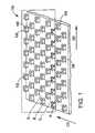
- FIG. 1is a perspective view of male fastener component with palm tree-shaped hooks.
- FIG. 2is an enlarged photograph of an example of the fastener of FIG. 1 .
- FIG. 3is an enlarged side view of one of the fastener elements.
- FIGS. 3A and 3Bare top and end views, respectively, of the fastener element of FIG. 3 .
- FIG. 4is a perspective view of an alternate palm tree hook shape.
- FIGS. 4A and 4Bare top and end views, respectively, of the fastener element of FIG. 4 .
- FIG. 5is an enlarged side view of a J-hook fastener element.
- FIGS. 6 and 6Aillustrate alternate molding processes for forming the fastener components.
- FIG. 7illustrates a variation of the process of FIG. 6 , for forming a laminated fastener.
- FIG. 7Ais an enlarged cross-section of a product formed by the process of FIG. 7 .
- a male touch fastener component 100includes a field of fastener elements 102 arranged in rows R extending outwardly from and integrally with a sheet-form base 104 . Spacing S between rows may be controlled by the manufacturing process and will be discussed further below.
- Fastener elements 102are palm tree-shaped hooks and are engageable in two directions along a plane (i.e., an engagement plane) perpendicular to sheet-form base 104 in the direction of rows R.
- Each fastener element 102includes two heads 106 extending from a single stem 108 .
- Male fastener component 100is designed to, for example, strongly engage a low pile height, loop touch fastener component, particularly a loop component with loops formed of, for example, a high strength multifilament yarn or a high strength monofilament.
- High strength loopsare desirable for fasteners for high strength applications requiring high cycle life, as the resist breakage at higher peel loads.
- high strength yarns and monofilamentsare made by extrusion.
- the processincludes a drawdown step to impart orientation on the yarn or monofilament so as to improve, for example, tenacity of the yarn or monofilament.
- High strength fibersmay also be formed by other methods, for example, by solution spinning.
- Suitable high strength loop filament materialsinclude, for example, polyamides, polyesters, polyurethanes, ultra-high molecular weight solution spun polyethylene (e.g., SPECTRA® polyethylene), aramids (e.g., KEVLAR®), acrylics and rigid rod polymers like poly(p-phenylene-2,6-benzobisoxazole).
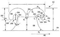
- fastener element 102has a substantially constant thickness from base to tip, and includes a stem 108 extending outwardly from and molded integrally with sheet-form base 104 .
- stem 108we refer to the stem 108 as beginning at the upper surface of base 104 and ending at an elevation where the inner crook surface is perpendicular to the base, an elevation 250 above which the inner crook surface begins to overhang the stem 108 or sheet-form base.
- Fastener element 102also includes two heads 106 extending in essentially opposite directions in an engagement plane. Heads 106 extend from distal end 250 of the stem to corresponding, oppositely-directed tips 252 .
- fastener element 102is an example of what is known in the art as a ‘palm-tree’ fastener element.
- the heads 106have upper surfaces that alone or together with the stem define a well 254 between the heads.
- Each head 106has a lower surface that rises up through an apex 258 and then falls again, forming an arched crook 256 for retaining loops of a mating female touch fastener component.
- the overall height A of fastener element 102is measured in side view perpendicular to sheet-form base 104 from the top of the sheet-form base.
- Under crook height Cis the distance measured in side view, perpendicular to the sheet-form base, between the lowermost extent of the tip 260 and the apex 258 of the crook.
- Entrance height Eis the distance measured in side view, perpendicular to the sheet-form base, from the top of the sheet-form base to the lowermost extent of tip 260 . If part of the stem is directly below the lowermost extent of the tip 260 , then the distance is measured from that portion of the stem directly below to the lowermost extent of the tip 260 .
- Head height J of fastener element 102is measured perpendicular to sheet-form base 104 from the lowermost extent of tip 260 to the highest elevation of the head 106 above the base. In general, J will be the difference between A and E.
- Well height Gis measured in side view from the lower extent of stem 108 to the lower extent of well 254 defined in the upper surface of the fastener element between the heads.
- Width L of the fastener elementis measured in side view and is the maximum lateral extent of the fastener element heads 106 as measured parallel to the sheet-form base.
- Hook thickness Kis the overall thickness of the fastener element, taken at elevation 250 corresponding to the upper end of stem 108 . In most cases other than instances where the heads have been formed subsequent to stem molding, the heads will lie completely within this hook thickness K. In the example shown, hook thickness is the same at all elevations.
- the product of head width L and thickness Kwe call the footprint of the fastener element, and is related to the area of contact between the hook product and a mating loop product during initial engagement, although it will be understood to not be an exact measure of such contact area.
- the front and rear surfaces of the stemdefine, in side profile, inclination angles ⁇ of about 23 degrees with respect to vertical, with the width of the stem tapering to narrower away from the base, both for strength and ease of molding.
- Under crook angle ⁇ mis an angle defined in the crook by inner surfaces of the head and stem, between a pair of line segments perpendicular to facing surfaces of the fastener element, in side view.
- Line segment 1 1is perpendicular to the forward edge of stem 108 at the elevation of the distal tip 260 of the head.
- Line segment 1 2is perpendicular to the under crook surface of the head at a point of inflection ‘X’ of the under head surface.
- line segment 1 2should be taken as perpendicular to the underside surface of the head just above such a corner or discontinuity.
- angle ⁇ mis measured from the upper side of line segment 1 1 , about the crook, to the upper side of line segment 1 2 .
- ⁇ mis 201 degrees.
- the overall fastener componenthas an overall hook footprint of 22.6 percent of the overall array area.
- FIG. 3Further description of the embodiment of FIG. 3 can be found in an application entitled “MULTIPLE-CROOK MALE TOUCH FASTENER ELEMENTS,” filed concurrently herewith and assigned U.S. Ser. No. 10/688,320, the disclosure of which is hereby incorporated in full by reference.
- fastener element 102 a of FIGS. 4 , 4 A and 4 Bhas a greatest thickness at its base, and tapers in thickness to the distal tips of the heads.
- fastener element 102 ahas the same profile as shown in FIG. 3 , and approximately the same dimensions listed above also apply to this example.
- Palm-tree fastener elementshave two identical crooks.
- some palm-tree fastener elementsare intentionally formed to have one head extending up higher than the other, such as to engage loops of differing heights.
- some palm-tree hooksare molded to have two identical crooks, but later processing alters one crook more than the other, such as discussed below.
- the fastener element 302 of FIG. 5defines only a single crook, and is thus an example of a ‘J-hook’ fastener element.
- head width Lis taken from the forwardmost edge of the hook head 306 to the rearmost extent of the hook stem 308 .
- the dimensions provided above with respect to FIG. 3apply equally to the J-hook of FIG. 5 .
- Fastener elements 302can be arranged in rows extending from a sheet-form base 304 , with hooks of adjacent rows facing in opposite directions. Other arrangements of such hooks are also envisioned.
- thermoplastic resin 200is extruded as a molten sheet from extruder 202 and introduced into nip 204 formed between a pressure roll 206 and a counter-rotating mold roll 208 defining fastener element-shaped cavities in its surface. Pressure in the nip causes thermoplastic resin 200 to enter these blind-ended forming cavities to form the fastener elements, while excess resin remains about the periphery of the mold roll and is molded between the rolls to form sheet-form base 104 . The thermoplastic resin is cooled as it proceeds along the periphery of the mold roll, solidifying the fastener elements, until it is stripped by stripper roll 212 .
- the molded fastener elementsdistend during de-molding, but tend to recover substantially their as-molded shape. It is generally understood that fastener element crooks molded to face downstream tend to distend slightly more than those molded to face upstream, and can remain more distended in the final product.
- the direction of travel of the material illustrated in FIG. 6is referred to as the “machine direction” (MD) of the material and defines the longitudinal direction of the resulting product, while the cross-machine direction (CD) is perpendicular to the machine direction within the plane of the sheet-form base. Further details regarding processing are described by Fischer, U.S. Pat. No. 4,775,310 and Clune et al., U.S. Pat. No. 6,202,260, the disclosures of which are hereby incorporated in full by reference.
- the mold roll 208comprises a face-to-face assembly of thin, circular plates or rings (not shown) that are, for example, about 0.003 inch to about 0.250 inch (0.0762 mm-6.35 mm) thick, some having cutouts in their periphery defining mold cavities and others having solid circumferences, serving to close the open sides of the mold cavities and serve as spacers, defining the spacing between adjacent fastener element rows.
- a fully “built up” mold rollmay have a width, for example, from about 0.75 inch to about 6 inches (1.91 cm-15.24 cm) or more and may contain, for example, from about 50 to 1000 or more individual rings. Further details regarding mold tooling are described by Fisher, U.S. Pat. No. 4,775,310. Additional tooling embodiments will also be described below.
- the cavities that made the fastener element shown in FIG. 3-3Bhave sharp edges and straight sidewalls and create fastener elements with substantially similar cross-sections through the thickness of the fastener element.
- Tooling with straight sidewalls and edgescan be made by, for example, laser cutting, wire EDM or electroforming. Further details regarding laser cutting and wire EDM mold tooling is described by Fisher, U.S. Pat. No. 4,775,310. The electroforming process is described by Clarner et al., U.S. Ser. No. 10/455,240, the disclosure of which is hereby incorporated in full by reference.
- fastener elements formed in cavities that have been, for example, photochemically etchedmay have rounded surfaces in some or all regions, from base to tip, such as those illustrated in FIGS. 4-4B .
- surfaces at the top of the headscan be made to taper to a point to give a wedge effect.
- a wedge-shapemay, for example, assist the entry of the crook into the face of a mating female fastener component.
- FIG. 6AAn alternate technique for molding fastener elements is shown in FIG. 6A .
- the processis similar to that described above with reference to FIG. 6 , except only a mold roll 208 is used, i.e., no pressure roll 206 is necessary.
- the extruder 202is shaped to conform to the periphery of the mold roll 208 and the extruded resin 200 is introduced under pressure directly to a gap 214 formed between mold roll 208 and extruder 202 .
- the molded fastener componentis stripped from the mold cavities by a stripper roll 212 as described above. Further details regarding this process are described by Akeno, U.S. Pat. Nos. 5,781,969 and 5,913,482, the disclosures of which are hereby incorporated in full by reference.
- a laminated male touch fastener component 101may be formed by introducing a pre-form material 215 into nip 204 between the mold and pressure rolls.
- pre-form material 215becomes laminated and bonded to the thermoplastic resin 200 simultaneously with the forming of the fastener elements.
- the resultcan be a contiguous molded structure, without weld lines, extending from the tips of the fastener elements into the pre-form material, where the resin can intimately bond with features or fibers of the material to form a strong, permanent bond. Further details regarding this process are described by Kennedy et al., U.S. Pat. No. 5,260,015, the disclosures of which is hereby incorporated in full by reference.
- pre-formed material 215is a loose knit scrim, such as Knit 3901 from Velcro USA in Manchester, N.H., although Velcro USA loop products 3900, 3905, and 3400 may also be employed.
- Knit 3901is a 2 bar Tricot knit nylon fabric which generally must be brushed or napped before it can be employed as the functioning loop of a hook and loop closure. However, it has been found to function well as a reinforcement when at least partially encapsulated by, or bonded to, the base resin contiguous with the resin forming the hooks, without brushing or napping. Reinforcing the base with such a scrim has been found to improve the stitch tear strength of the product, providing a resin-base hook product practical for attachment by sewing or stitching. Further details regarding scrim materials are described an application entitled “PLASTIC SHEET REINFORCEMENT,” filed concurrently herewith and assigned U.S. Ser. No. 10/688,301, the disclosure of which is hereby incorporated in full by reference.
- the fastener elementsare not molded in their final form.
- the fastener componentmay be routed through subsequent processing station 230 to finalize the form of the fastener elements.
- Such subsequent processingmay include “flat-topping” overhanging fastener element preforms, as described by Provost, U.S. Pat. No. 5,953,797, and Akeno, U.S. Pat. No. 5,781,969, the disclosure of both of which is hereby incorporated in full by reference.
- even straight molded stemsmay be subsequently processed to result in fastener elements having the properties disclosed herein.
- 3 and 5can also be formed by a cut-and-stretch method, such as the method disclosed in Nestegard, U.S. Pat. No. 4,895,569, for example.
- moldable resinis extruded through a die with openings shaped in the desired hook profile, then the extruded rails are cut transverse to the extrusion direction, and the base stretched in the extrusion direction to separate the rails into rows of discrete fastener elements.
- This procedureresults in fastener elements with broad sides that are cut rather than molded, as in the processes described above, and with profile edges formed by sliding resin through a shaped die rather than a filling cavity.
Landscapes
- Engineering & Computer Science (AREA)
- Mechanical Engineering (AREA)
- Slide Fasteners, Snap Fasteners, And Hook Fasteners (AREA)
- Polarising Elements (AREA)
- Electroluminescent Light Sources (AREA)
- Magnetic Heads (AREA)
Abstract
Description
| Dimension | Inches | Millimeters | ||
| A | 0.025 | 0.635 | ||
| C | 0.0064 | 0.163 | ||
| E | 0.0105 | 0.267 | ||
| G | 0.0122 | 0.310 | ||
| J | 0.0145 | 0.368 | ||
| K | 0.012 | 0.305 | ||
| L | 0.0497 | 1.262 | ||
| R1 | 0.0011 | 0.279 | ||
| R2 | 0.0090 | 0.229 | ||
| R3 | 0.0026 | 0.0660 | ||
| R4 | 0.0040 | 0.102 | ||
| R5 | 0.0107 | 0.272 | ||
| R6 | 0.0164 | 0.417 | ||
Claims (38)
Priority Applications (10)
| Application Number | Priority Date | Filing Date | Title |
|---|---|---|---|
| US10/688,031US7716792B2 (en) | 2003-10-15 | 2003-10-15 | Touch fastener elements |
| PCT/US2004/033664WO2005037008A2 (en) | 2003-10-15 | 2004-10-13 | Touch fastener elements |
| EP04794898AEP1677639B1 (en) | 2003-10-15 | 2004-10-13 | Touch fastener elements |
| AT04794898TATE367106T1 (en) | 2003-10-15 | 2004-10-13 | VELCRO ELEMENTS |
| ES07002857TES2306442T3 (en) | 2003-10-15 | 2004-10-13 | CONTACT FIXING ELEMENTS. |
| EP07002857AEP1785052B1 (en) | 2003-10-15 | 2004-10-13 | Touch fastener elements |
| DE602004014652TDE602004014652D1 (en) | 2003-10-15 | 2004-10-13 | Velcro elements |
| CN200480037153.8ACN1893849A (en) | 2003-10-15 | 2004-10-13 | Touch fastener elements |
| ES04794898TES2288697T3 (en) | 2003-10-15 | 2004-10-13 | CONTACT FIXING ELEMENTS. |
| DE602004007678TDE602004007678T2 (en) | 2003-10-15 | 2004-10-13 | VELCRO ELEMENTS |
Applications Claiming Priority (1)
| Application Number | Priority Date | Filing Date | Title |
|---|---|---|---|
| US10/688,031US7716792B2 (en) | 2003-10-15 | 2003-10-15 | Touch fastener elements |
Publications (2)
| Publication Number | Publication Date |
|---|---|
| US20050081344A1 US20050081344A1 (en) | 2005-04-21 |
| US7716792B2true US7716792B2 (en) | 2010-05-18 |
Family
ID=34465561
Family Applications (1)
| Application Number | Title | Priority Date | Filing Date |
|---|---|---|---|
| US10/688,031Active2026-09-17US7716792B2 (en) | 2003-10-15 | 2003-10-15 | Touch fastener elements |
Country Status (7)
| Country | Link |
|---|---|
| US (1) | US7716792B2 (en) |
| EP (2) | EP1677639B1 (en) |
| CN (1) | CN1893849A (en) |
| AT (1) | ATE367106T1 (en) |
| DE (2) | DE602004007678T2 (en) |
| ES (2) | ES2306442T3 (en) |
| WO (1) | WO2005037008A2 (en) |
Cited By (6)
| Publication number | Priority date | Publication date | Assignee | Title |
|---|---|---|---|---|
| US20080229556A1 (en)* | 2004-03-23 | 2008-09-25 | Pavel Hammer | Intermediate Fixing Element |
| US9474334B2 (en) | 2012-11-13 | 2016-10-25 | Ossur Hf | Fastener member for affixation to a structure in an orthopedic device and method for securing the same |
| US20170217157A1 (en)* | 2014-07-10 | 2017-08-03 | Velcro BVBA | Printing plate connection systems |
| WO2018114778A1 (en) | 2016-12-22 | 2018-06-28 | Velcro BVBA | Multi-closure energy dissipating touch fastener links and method of arranging energy dissipating touch fastener link |
| WO2018114869A1 (en) | 2016-12-22 | 2018-06-28 | Velcro BVBA | Energy dissipating touch fastener links |
| US11083252B2 (en) | 2017-09-22 | 2021-08-10 | Ykk Corporation | Fastening tape with reinforced hooks |
Families Citing this family (8)
| Publication number | Priority date | Publication date | Assignee | Title |
|---|---|---|---|---|
| FR2922805B1 (en)* | 2007-10-26 | 2013-09-06 | Aplix Sa | INSERTION BLOCK FOR THE FORMATION OF A FIELD OF HOOKS ON AN INJECTION MOLDED OBJECT AND A MOLDED OBJECT HAVING A HOOK FIELD OF THIS TYPE |
| CN103002764B (en)* | 2010-04-27 | 2017-02-15 | 维尔克有限公司 | Male touch fastener element |
| CN102353312B (en)* | 2011-07-14 | 2013-06-05 | 杭州发达齿轮箱集团有限公司 | Tooth-thickness measuring tool for small-angle variable-tooth-thickness gear and measuring method thereof |
| EP2679112A1 (en) | 2012-06-26 | 2014-01-01 | 3M Innovative Properties Company | Method for manufacturing fasteners and precursor webs, a fastener and a precursor web |
| BR112015008344B1 (en)* | 2012-10-15 | 2021-04-27 | Velcro BVBA | METHOD OF FORMATION OF A PRODUCT HOLDING CONTACT, AND PRODUCT HOLDING CONTACT |
| JP6031530B2 (en)* | 2012-10-26 | 2016-11-24 | Ykk株式会社 | Male surface fastener, diaper, and fixing method |
| EP3700384B2 (en) | 2017-10-27 | 2025-07-23 | Gottlieb Binder GmbH & Co. KG | Precursor web for reclosable fastener hooks and methods of making |
| EP3821749B1 (en)* | 2018-07-09 | 2025-05-14 | YKK Corporation | Molded surface fastener |
Citations (50)
| Publication number | Priority date | Publication date | Assignee | Title |
|---|---|---|---|---|
| US3387345A (en) | 1966-04-01 | 1968-06-11 | Velcro Sa Soulie | Separable fastening device |
| US3417440A (en)* | 1961-12-19 | 1968-12-24 | Velcro Sa Soulie | Hook and loop fastener |
| US3426363A (en) | 1965-02-17 | 1969-02-11 | American Velcro Inc | Composite length of pile fabric sheet material |
| US4165555A (en) | 1975-09-29 | 1979-08-28 | Boxer Robert K | Hook-and-pile strips for socks and the like |
| US4402690A (en) | 1980-10-21 | 1983-09-06 | Robin Redfern | High absorbency, contoured, reusable diaper |
| US4410327A (en) | 1980-04-14 | 1983-10-18 | Laboratories (South Africa)(Proprietary) Ltd. | Diaper |
| WO1987006522A1 (en)* | 1986-04-25 | 1987-11-05 | Actief N.V. | Separable fastener member and method and apparatus for producing same |
| US4870725A (en) | 1987-01-12 | 1989-10-03 | Velcro Industries B.V. | Pop-through touch fastener |
| EP0382024A1 (en) | 1989-01-31 | 1990-08-16 | The Procter & Gamble Company | Improved mechanical fastening prong |
| US4984339A (en) | 1988-10-20 | 1991-01-15 | Velcro Industries B.V. | Hook for hook and loop fasteners |
| US5058247A (en)* | 1989-01-31 | 1991-10-22 | The Procter & Gamble Company | Mechanical fastening prong |
| CN1057575A (en) | 1990-06-28 | 1992-01-08 | 普罗格特—甘布尔公司 | Improved production method of mechanical coupling parts and mechanical coupling parts produced therewith |
| US5176670A (en) | 1988-12-20 | 1993-01-05 | Kimberly-Clark Corporation | Disposable diaper with improved mechanical fastening system |
| US5318741A (en) | 1989-01-31 | 1994-06-07 | The Procter & Gamble Company | Process of making a refastenable mechanical fastening system |
| US5326415A (en) | 1991-06-21 | 1994-07-05 | The Procter & Gamble Company | Screen printing method for manufacturing a refastenable mechanical fastening system and fastening system produced therefrom |
| US5325569A (en) | 1992-10-30 | 1994-07-05 | The Procter & Gamble Company | Refastenable mechanical fastening system having particular viscosity and rheology characteristics |
| US5326612A (en) | 1991-05-20 | 1994-07-05 | The Procter & Gamble Company | Nonwoven female component for refastenable fastening device and method of making the same |
| US5339499A (en) | 1993-02-16 | 1994-08-23 | Velcro Industries B.V. | Hook design for a hook and loop fastener |
| US5368549A (en) | 1991-03-06 | 1994-11-29 | Aircast, Inc. | Method for injection-molding an orthopedic device and product of the method |
| US5369852A (en) | 1991-12-12 | 1994-12-06 | Kuraray Co., Ltd. | Mixed hook/loop separable fastener and process for its production |
| US5369853A (en) | 1992-07-31 | 1994-12-06 | Yoshida Kogyo K.K. | Hook-and-loop fastener |
| US5392498A (en) | 1992-12-10 | 1995-02-28 | The Proctor & Gamble Company | Non-abrasive skin friendly mechanical fastening system |
| US5399177A (en) | 1991-10-25 | 1995-03-21 | The Procter & Gamble Company | Refastenable adhesive fastening systems for disposable absorbent articles |
| US5399418A (en) | 1991-12-21 | 1995-03-21 | Erno Raumfahrttechnik Gmbh | Multi-ply textile fabric especially for protection suits and the like |
| US5540673A (en) | 1989-01-31 | 1996-07-30 | The Procter & Gamble Company | Refastenable mechanical fastening system |
| US5551130A (en) | 1993-09-14 | 1996-09-03 | Ykk Corporation | Hook structure of molded surface fastener |
| US5586371A (en)* | 1994-11-08 | 1996-12-24 | The Procter & Gamble Company | Method for manufacturing refastenable fastening systems including a female loop fastening component and the product produced therefrom |
| US5604963A (en) | 1994-10-24 | 1997-02-25 | Ykk Corporation | Hook structure for molded surface fastener |
| US5607345A (en) | 1994-01-13 | 1997-03-04 | Minnesota Mining And Manufacturing Company | Abrading apparatus |
| US5615460A (en) | 1994-06-06 | 1997-04-01 | The Procter & Gamble Company | Female component for refastenable fastening device having regions of differential extensibility |
| US5655268A (en) | 1995-09-14 | 1997-08-12 | Ykk Corporation | Button-substitute fastening device |
| US5669120A (en) | 1995-05-09 | 1997-09-23 | Ykk Corporation | Molded surface fastener |
| US5781969A (en) | 1996-06-06 | 1998-07-21 | Ykk Corporation | Molded surface fastener |
| US5845375A (en) | 1990-09-21 | 1998-12-08 | Minnesota Mining And Manufacturing Company | Mushroom-type hook strip for a mechanical fastener |
| US5875527A (en) | 1997-08-29 | 1999-03-02 | Velcro Industries B.V. | Fastener element arrangement |
| US5900350A (en) | 1996-06-06 | 1999-05-04 | Velcro Industries B.V. | Molding methods, molds and products |
| US5953797A (en) | 1996-10-09 | 1999-09-21 | Velcro Industries B.V. | Hook fasteners and methods of manufacture |
| US5974635A (en) | 1997-08-05 | 1999-11-02 | Ykk Corporation | Female engaging member of surface fastener and method of manufacturing the same |
| US6039911A (en) | 1997-01-09 | 2000-03-21 | 3M Innovative Properties Company | Method for capping stem fasteners |
| US6054091A (en)* | 1996-10-03 | 2000-04-25 | Minnesota Mining And Manufacturing Co. | J hook-type hook strip for a mechanical fastener |
| US6066281A (en) | 1998-06-16 | 2000-05-23 | Velcro Industries B.V. | Fastener products and their production |
| US6209177B1 (en) | 1998-01-22 | 2001-04-03 | Ykk Corporation | Molded surface fastener, and molding method and molding apparatus of the same |
| US6248419B1 (en)* | 1991-08-16 | 2001-06-19 | Velcro Industries B.V. | Laminated hook fastener |
| WO2002060294A1 (en) | 2001-01-31 | 2002-08-08 | Velcro Industries B.V. | Direct hook engagement |
| US20020116799A1 (en)* | 2001-02-26 | 2002-08-29 | Martin Timothy R. | Skin-friendly hook fastening component |
| US20020124359A1 (en) | 2001-03-08 | 2002-09-12 | Ykk Corporation | Integral molded surface fastener, and continuous manufacturing method and continuous manufacturing apparatus therefor |
| US20030012921A1 (en)* | 1997-09-10 | 2003-01-16 | Gallant Christopher M. | Fastener element molding |
| US6579161B1 (en)* | 1994-01-13 | 2003-06-17 | 3M Innovative Properties Company | Abrasive article |
| US20030182776A1 (en) | 2002-01-15 | 2003-10-02 | 3M Innovative Properties Company | Heat treated profile extruded hook |
| US20040068848A1 (en)* | 2002-01-15 | 2004-04-15 | Ausen Ronald W. | Heat treated profile extruded hook |
- 2003
- 2003-10-15USUS10/688,031patent/US7716792B2/enactiveActive
- 2004
- 2004-10-13CNCN200480037153.8Apatent/CN1893849A/enactivePending
- 2004-10-13DEDE602004007678Tpatent/DE602004007678T2/ennot_activeExpired - Lifetime
- 2004-10-13ATAT04794898Tpatent/ATE367106T1/ennot_activeIP Right Cessation
- 2004-10-13EPEP04794898Apatent/EP1677639B1/ennot_activeExpired - Lifetime
- 2004-10-13WOPCT/US2004/033664patent/WO2005037008A2/enactiveIP Right Grant
- 2004-10-13EPEP07002857Apatent/EP1785052B1/ennot_activeExpired - Lifetime
- 2004-10-13DEDE602004014652Tpatent/DE602004014652D1/ennot_activeExpired - Lifetime
- 2004-10-13ESES07002857Tpatent/ES2306442T3/ennot_activeExpired - Lifetime
- 2004-10-13ESES04794898Tpatent/ES2288697T3/ennot_activeExpired - Lifetime
Patent Citations (55)
| Publication number | Priority date | Publication date | Assignee | Title |
|---|---|---|---|---|
| US3417440A (en)* | 1961-12-19 | 1968-12-24 | Velcro Sa Soulie | Hook and loop fastener |
| US3426363A (en) | 1965-02-17 | 1969-02-11 | American Velcro Inc | Composite length of pile fabric sheet material |
| US3387345A (en) | 1966-04-01 | 1968-06-11 | Velcro Sa Soulie | Separable fastening device |
| US4165555A (en) | 1975-09-29 | 1979-08-28 | Boxer Robert K | Hook-and-pile strips for socks and the like |
| US4410327A (en) | 1980-04-14 | 1983-10-18 | Laboratories (South Africa)(Proprietary) Ltd. | Diaper |
| US4402690A (en) | 1980-10-21 | 1983-09-06 | Robin Redfern | High absorbency, contoured, reusable diaper |
| WO1987006522A1 (en)* | 1986-04-25 | 1987-11-05 | Actief N.V. | Separable fastener member and method and apparatus for producing same |
| US4870725A (en) | 1987-01-12 | 1989-10-03 | Velcro Industries B.V. | Pop-through touch fastener |
| US4984339A (en) | 1988-10-20 | 1991-01-15 | Velcro Industries B.V. | Hook for hook and loop fasteners |
| US5176670A (en) | 1988-12-20 | 1993-01-05 | Kimberly-Clark Corporation | Disposable diaper with improved mechanical fastening system |
| EP0382024A1 (en) | 1989-01-31 | 1990-08-16 | The Procter & Gamble Company | Improved mechanical fastening prong |
| CN1047021A (en) | 1989-01-31 | 1990-11-21 | 普罗格特-甘布尔公司 | Improved mechanical fastening prong |
| US5058247A (en)* | 1989-01-31 | 1991-10-22 | The Procter & Gamble Company | Mechanical fastening prong |
| US5318741A (en) | 1989-01-31 | 1994-06-07 | The Procter & Gamble Company | Process of making a refastenable mechanical fastening system |
| US5540673A (en) | 1989-01-31 | 1996-07-30 | The Procter & Gamble Company | Refastenable mechanical fastening system |
| CN1057575A (en) | 1990-06-28 | 1992-01-08 | 普罗格特—甘布尔公司 | Improved production method of mechanical coupling parts and mechanical coupling parts produced therewith |
| US5116563A (en)* | 1990-06-28 | 1992-05-26 | The Procter & Gamble Company | Process for producing a mechanical fastener |
| US5845375A (en) | 1990-09-21 | 1998-12-08 | Minnesota Mining And Manufacturing Company | Mushroom-type hook strip for a mechanical fastener |
| US5368549A (en) | 1991-03-06 | 1994-11-29 | Aircast, Inc. | Method for injection-molding an orthopedic device and product of the method |
| US5326612A (en) | 1991-05-20 | 1994-07-05 | The Procter & Gamble Company | Nonwoven female component for refastenable fastening device and method of making the same |
| US5326415A (en) | 1991-06-21 | 1994-07-05 | The Procter & Gamble Company | Screen printing method for manufacturing a refastenable mechanical fastening system and fastening system produced therefrom |
| US6248419B1 (en)* | 1991-08-16 | 2001-06-19 | Velcro Industries B.V. | Laminated hook fastener |
| US5399177A (en) | 1991-10-25 | 1995-03-21 | The Procter & Gamble Company | Refastenable adhesive fastening systems for disposable absorbent articles |
| US5369852A (en) | 1991-12-12 | 1994-12-06 | Kuraray Co., Ltd. | Mixed hook/loop separable fastener and process for its production |
| US5399418A (en) | 1991-12-21 | 1995-03-21 | Erno Raumfahrttechnik Gmbh | Multi-ply textile fabric especially for protection suits and the like |
| US5369853A (en) | 1992-07-31 | 1994-12-06 | Yoshida Kogyo K.K. | Hook-and-loop fastener |
| US5325569A (en) | 1992-10-30 | 1994-07-05 | The Procter & Gamble Company | Refastenable mechanical fastening system having particular viscosity and rheology characteristics |
| US5392498A (en) | 1992-12-10 | 1995-02-28 | The Proctor & Gamble Company | Non-abrasive skin friendly mechanical fastening system |
| US5339499A (en) | 1993-02-16 | 1994-08-23 | Velcro Industries B.V. | Hook design for a hook and loop fastener |
| US5551130A (en) | 1993-09-14 | 1996-09-03 | Ykk Corporation | Hook structure of molded surface fastener |
| US5607345A (en) | 1994-01-13 | 1997-03-04 | Minnesota Mining And Manufacturing Company | Abrading apparatus |
| US6579161B1 (en)* | 1994-01-13 | 2003-06-17 | 3M Innovative Properties Company | Abrasive article |
| US5615460A (en) | 1994-06-06 | 1997-04-01 | The Procter & Gamble Company | Female component for refastenable fastening device having regions of differential extensibility |
| US5604963A (en) | 1994-10-24 | 1997-02-25 | Ykk Corporation | Hook structure for molded surface fastener |
| US5586371A (en)* | 1994-11-08 | 1996-12-24 | The Procter & Gamble Company | Method for manufacturing refastenable fastening systems including a female loop fastening component and the product produced therefrom |
| US5669120A (en) | 1995-05-09 | 1997-09-23 | Ykk Corporation | Molded surface fastener |
| US5655268A (en) | 1995-09-14 | 1997-08-12 | Ykk Corporation | Button-substitute fastening device |
| US5781969A (en) | 1996-06-06 | 1998-07-21 | Ykk Corporation | Molded surface fastener |
| US6131251A (en) | 1996-06-06 | 2000-10-17 | Velcro Industries B.V. | Molded hook member for a touch fastener |
| US6163939A (en) | 1996-06-06 | 2000-12-26 | Velcro Industries, B.V. | Molding of fastening hooks and other devices |
| US5900350A (en) | 1996-06-06 | 1999-05-04 | Velcro Industries B.V. | Molding methods, molds and products |
| US6054091A (en)* | 1996-10-03 | 2000-04-25 | Minnesota Mining And Manufacturing Co. | J hook-type hook strip for a mechanical fastener |
| US5953797A (en) | 1996-10-09 | 1999-09-21 | Velcro Industries B.V. | Hook fasteners and methods of manufacture |
| US6039911A (en) | 1997-01-09 | 2000-03-21 | 3M Innovative Properties Company | Method for capping stem fasteners |
| US5974635A (en) | 1997-08-05 | 1999-11-02 | Ykk Corporation | Female engaging member of surface fastener and method of manufacturing the same |
| US5875527A (en) | 1997-08-29 | 1999-03-02 | Velcro Industries B.V. | Fastener element arrangement |
| US20030012921A1 (en)* | 1997-09-10 | 2003-01-16 | Gallant Christopher M. | Fastener element molding |
| US6209177B1 (en) | 1998-01-22 | 2001-04-03 | Ykk Corporation | Molded surface fastener, and molding method and molding apparatus of the same |
| US6066281A (en) | 1998-06-16 | 2000-05-23 | Velcro Industries B.V. | Fastener products and their production |
| WO2002060294A1 (en) | 2001-01-31 | 2002-08-08 | Velcro Industries B.V. | Direct hook engagement |
| US20020116799A1 (en)* | 2001-02-26 | 2002-08-29 | Martin Timothy R. | Skin-friendly hook fastening component |
| US20020124359A1 (en) | 2001-03-08 | 2002-09-12 | Ykk Corporation | Integral molded surface fastener, and continuous manufacturing method and continuous manufacturing apparatus therefor |
| CN1374050A (en) | 2001-03-08 | 2002-10-16 | Ykk株式会社 | Integral moulded surface fastener, continuous producing method and its continuous producing equipment |
| US20030182776A1 (en) | 2002-01-15 | 2003-10-02 | 3M Innovative Properties Company | Heat treated profile extruded hook |
| US20040068848A1 (en)* | 2002-01-15 | 2004-04-15 | Ausen Ronald W. | Heat treated profile extruded hook |
Non-Patent Citations (2)
| Title |
|---|
| PCT/US02/02570, International Search Report. |
| Second Office Action, Chinese Patent Application No. 2004800371538, dated Jan. 16, 2009. |
Cited By (11)
| Publication number | Priority date | Publication date | Assignee | Title |
|---|---|---|---|---|
| US20080229556A1 (en)* | 2004-03-23 | 2008-09-25 | Pavel Hammer | Intermediate Fixing Element |
| US8281463B2 (en)* | 2004-03-23 | 2012-10-09 | Aplix | Intermediate fixing element |
| US9474334B2 (en) | 2012-11-13 | 2016-10-25 | Ossur Hf | Fastener member for affixation to a structure in an orthopedic device and method for securing the same |
| US10245170B2 (en) | 2012-11-13 | 2019-04-02 | Ossur Hf | Fastener member for affixation to a structure in an orthopedic device and method for securing the same |
| US20170217157A1 (en)* | 2014-07-10 | 2017-08-03 | Velcro BVBA | Printing plate connection systems |
| US10518525B2 (en)* | 2014-07-10 | 2019-12-31 | Velcro BVBA | Printing plate connection systems |
| WO2018114778A1 (en) | 2016-12-22 | 2018-06-28 | Velcro BVBA | Multi-closure energy dissipating touch fastener links and method of arranging energy dissipating touch fastener link |
| WO2018114869A1 (en) | 2016-12-22 | 2018-06-28 | Velcro BVBA | Energy dissipating touch fastener links |
| US10537758B2 (en) | 2016-12-22 | 2020-01-21 | Velcro BVBA | Energy dissipating touch fastener links |
| US10844922B2 (en) | 2016-12-22 | 2020-11-24 | Velcro BVBA | Multi-closure energy dissipating touch fastener links |
| US11083252B2 (en) | 2017-09-22 | 2021-08-10 | Ykk Corporation | Fastening tape with reinforced hooks |
Also Published As
| Publication number | Publication date |
|---|---|
| EP1785052A3 (en) | 2007-06-06 |
| US20050081344A1 (en) | 2005-04-21 |
| WO2005037008A3 (en) | 2005-07-28 |
| DE602004007678T2 (en) | 2008-04-10 |
| DE602004014652D1 (en) | 2008-08-07 |
| ES2288697T3 (en) | 2008-01-16 |
| WO2005037008A2 (en) | 2005-04-28 |
| ATE367106T1 (en) | 2007-08-15 |
| EP1677639A2 (en) | 2006-07-12 |
| EP1677639B1 (en) | 2007-07-18 |
| ES2306442T3 (en) | 2008-11-01 |
| EP1785052B1 (en) | 2008-06-25 |
| DE602004007678D1 (en) | 2007-08-30 |
| EP1785052A2 (en) | 2007-05-16 |
| CN1893849A (en) | 2007-01-10 |
Similar Documents
| Publication | Publication Date | Title |
|---|---|---|
| US8898869B2 (en) | Male touch fastener element | |
| US7520033B2 (en) | Multiple-crook male touch fastener elements | |
| US7716792B2 (en) | Touch fastener elements | |
| US5131119A (en) | Hook structure for integrally molded surface fastener | |
| US5884374A (en) | Fastener members and apparatus for their fabrication | |
| US5685050A (en) | Hook structure for molded surface fastener | |
| US5604963A (en) | Hook structure for molded surface fastener | |
| EP1677641B1 (en) | Low profile touch fastener | |
| US20060200952A1 (en) | Touch fastener element loop retention | |
| HK1003360B (en) | Molded surface fastener |
Legal Events
| Date | Code | Title | Description |
|---|---|---|---|
| AS | Assignment | Owner name:VELCRO INDUSTRIES B.V., NETHERLANDS ANTILLES Free format text:ASSIGNMENT OF ASSIGNORS INTEREST;ASSIGNOR:CLARNER, MARK A.;REEL/FRAME:014928/0534 Effective date:20031229 Owner name:VELCRO INDUSTRIES B.V.,NETHERLANDS ANTILLES Free format text:ASSIGNMENT OF ASSIGNORS INTEREST;ASSIGNOR:CLARNER, MARK A.;REEL/FRAME:014928/0534 Effective date:20031229 | |
| STCF | Information on status: patent grant | Free format text:PATENTED CASE | |
| FPAY | Fee payment | Year of fee payment:4 | |
| AS | Assignment | Owner name:VELCRO BVBA, BELGIUM Free format text:ASSIGNMENT OF ASSIGNORS INTEREST;ASSIGNOR:VELCRO INDUSTRIES B.V.;REEL/FRAME:038528/0767 Effective date:20160415 | |
| MAFP | Maintenance fee payment | Free format text:PAYMENT OF MAINTENANCE FEE, 8TH YEAR, LARGE ENTITY (ORIGINAL EVENT CODE: M1552) Year of fee payment:8 | |
| AS | Assignment | Owner name:VELCRO IP HOLDINGS LLC, NEW HAMPSHIRE Free format text:ASSIGNMENT OF ASSIGNORS INTEREST;ASSIGNOR:VELCRO BVBA;REEL/FRAME:054891/0107 Effective date:20201222 | |
| MAFP | Maintenance fee payment | Free format text:PAYMENT OF MAINTENANCE FEE, 12TH YEAR, LARGE ENTITY (ORIGINAL EVENT CODE: M1553); ENTITY STATUS OF PATENT OWNER: LARGE ENTITY Year of fee payment:12 |