US7715918B2 - Muscle energy converter with smooth continuous tissue interface - Google Patents
Muscle energy converter with smooth continuous tissue interfaceDownload PDFInfo
- Publication number
- US7715918B2 US7715918B2US11/550,653US55065306AUS7715918B2US 7715918 B2US7715918 B2US 7715918B2US 55065306 AUS55065306 AUS 55065306AUS 7715918 B2US7715918 B2US 7715918B2
- Authority
- US
- United States
- Prior art keywords
- converter
- energy
- relatively stationary
- tension elements
- muscle
- Prior art date
- Legal status (The legal status is an assumption and is not a legal conclusion. Google has not performed a legal analysis and makes no representation as to the accuracy of the status listed.)
- Expired - Fee Related, expires
Links
- 210000003205muscleAnatomy0.000titleclaimsdescription34
- 210000001519tissueAnatomy0.000titledescription12
- 210000002027skeletal muscleAnatomy0.000claimsabstractdescription25
- 239000000835fiberSubstances0.000claimsdescription22
- 238000010168coupling processMethods0.000claimsdescription16
- 238000005859coupling reactionMethods0.000claimsdescription16
- 230000033001locomotionEffects0.000claimsdescription16
- 230000006835compressionEffects0.000claimsdescription12
- 238000007906compressionMethods0.000claimsdescription12
- 239000012530fluidSubstances0.000claimsdescription11
- 230000008878couplingEffects0.000claimsdescription8
- 239000013078crystalSubstances0.000claimsdescription6
- 238000012545processingMethods0.000abstractdescription31
- 238000000034methodMethods0.000abstractdescription20
- 230000008602contractionEffects0.000abstractdescription6
- 239000000463materialSubstances0.000description28
- RTAQQCXQSZGOHL-UHFFFAOYSA-NTitaniumChemical compound[Ti]RTAQQCXQSZGOHL-UHFFFAOYSA-N0.000description9
- 239000007788liquidSubstances0.000description8
- 229910052751metalInorganic materials0.000description8
- 239000002184metalSubstances0.000description8
- 239000010936titaniumSubstances0.000description8
- 238000010276constructionMethods0.000description6
- 229910001220stainless steelInorganic materials0.000description6
- 210000002435tendonAnatomy0.000description6
- 229910052719titaniumInorganic materials0.000description6
- 238000005452bendingMethods0.000description5
- 230000005540biological transmissionEffects0.000description5
- 238000006073displacement reactionMethods0.000description5
- 239000013536elastomeric materialSubstances0.000description5
- 206010016256fatigueDiseases0.000description5
- 229920000642polymerPolymers0.000description5
- 239000007787solidSubstances0.000description5
- 239000010935stainless steelSubstances0.000description5
- WYTGDNHDOZPMIW-RCBQFDQVSA-NalstonineNatural productsC1=CC2=C3C=CC=CC3=NC2=C2N1C[C@H]1[C@H](C)OC=C(C(=O)OC)[C@H]1C2WYTGDNHDOZPMIW-RCBQFDQVSA-N0.000description4
- 230000008901benefitEffects0.000description4
- 238000013461designMethods0.000description4
- 238000011065in-situ storageMethods0.000description4
- 229920002635polyurethanePolymers0.000description4
- 239000004814polyurethaneSubstances0.000description4
- 230000000747cardiac effectEffects0.000description3
- 239000000919ceramicSubstances0.000description3
- 239000002131composite materialSubstances0.000description3
- 125000004122cyclic groupChemical group0.000description3
- 239000012212insulatorSubstances0.000description3
- 230000036316preloadEffects0.000description3
- 125000006850spacer groupChemical group0.000description3
- 238000004804windingMethods0.000description3
- 229910001200FerrotitaniumInorganic materials0.000description2
- 206010019280Heart failuresDiseases0.000description2
- 241001465754MetazoaSpecies0.000description2
- 230000009471actionEffects0.000description2
- 239000000853adhesiveSubstances0.000description2
- 230000001070adhesive effectEffects0.000description2
- 238000013459approachMethods0.000description2
- 210000000988bone and boneAnatomy0.000description2
- 229910052799carbonInorganic materials0.000description2
- 238000005094computer simulationMethods0.000description2
- 230000001143conditioned effectEffects0.000description2
- 239000004020conductorSubstances0.000description2
- 239000011162core materialSubstances0.000description2
- 230000007423decreaseEffects0.000description2
- 230000000694effectsEffects0.000description2
- 229920001971elastomerPolymers0.000description2
- 239000000806elastomerSubstances0.000description2
- 230000005672electromagnetic fieldEffects0.000description2
- 230000006698inductionEffects0.000description2
- 238000003780insertionMethods0.000description2
- 230000037431insertionEffects0.000description2
- 230000007774longtermEffects0.000description2
- 238000005461lubricationMethods0.000description2
- 239000011159matrix materialSubstances0.000description2
- 230000007246mechanismEffects0.000description2
- 239000012528membraneSubstances0.000description2
- 230000004118muscle contractionEffects0.000description2
- 210000005036nerveAnatomy0.000description2
- 230000000399orthopedic effectEffects0.000description2
- 229920002379silicone rubberPolymers0.000description2
- 239000004945silicone rubberSubstances0.000description2
- 239000000126substanceSubstances0.000description2
- 238000003466weldingMethods0.000description2
- OKTJSMMVPCPJKN-UHFFFAOYSA-NCarbonChemical compound[C]OKTJSMMVPCPJKN-UHFFFAOYSA-N0.000description1
- 229920000049Carbon (fiber)Polymers0.000description1
- 206010011224CoughDiseases0.000description1
- 239000004593EpoxySubstances0.000description1
- 239000004698PolyethyleneSubstances0.000description1
- 229910000831SteelInorganic materials0.000description1
- 230000004913activationEffects0.000description1
- 230000004075alterationEffects0.000description1
- 239000000560biocompatible materialSubstances0.000description1
- 239000004917carbon fiberSubstances0.000description1
- 239000003054catalystSubstances0.000description1
- 229910010293ceramic materialInorganic materials0.000description1
- 238000006243chemical reactionMethods0.000description1
- 210000000038chestAnatomy0.000description1
- 238000000576coating methodMethods0.000description1
- 238000006880cross-coupling reactionMethods0.000description1
- 229910003460diamondInorganic materials0.000description1
- 239000010432diamondSubstances0.000description1
- 230000005684electric fieldEffects0.000description1
- 238000004870electrical engineeringMethods0.000description1
- 238000010292electrical insulationMethods0.000description1
- 238000004146energy storageMethods0.000description1
- 238000002682general surgeryMethods0.000description1
- 238000007373indentationMethods0.000description1
- 230000001939inductive effectEffects0.000description1
- 230000003993interactionEffects0.000description1
- 239000000696magnetic materialSubstances0.000description1
- 210000004779membrane envelopeAnatomy0.000description1
- VNWKTOKETHGBQD-UHFFFAOYSA-NmethaneChemical compoundCVNWKTOKETHGBQD-UHFFFAOYSA-N0.000description1
- 230000000116mitigating effectEffects0.000description1
- 239000000203mixtureSubstances0.000description1
- 238000012986modificationMethods0.000description1
- 230000004048modificationEffects0.000description1
- 210000000062pectoralis majorAnatomy0.000description1
- 230000000149penetrating effectEffects0.000description1
- 229920000728polyesterPolymers0.000description1
- -1polyethylenePolymers0.000description1
- 229920000573polyethylenePolymers0.000description1
- 229920003225polyurethane elastomerPolymers0.000description1
- 238000005381potential energyMethods0.000description1
- 230000002250progressing effectEffects0.000description1
- 210000001139rectus abdominisAnatomy0.000description1
- 238000004064recyclingMethods0.000description1
- 230000009467reductionEffects0.000description1
- 230000003014reinforcing effectEffects0.000description1
- 230000003252repetitive effectEffects0.000description1
- 239000011347resinSubstances0.000description1
- 229920005989resinPolymers0.000description1
- 230000029058respiratory gaseous exchangeEffects0.000description1
- 231100000817safety factorToxicity0.000description1
- 230000037390scarringEffects0.000description1
- 238000007789sealingMethods0.000description1
- 238000004904shorteningMethods0.000description1
- 239000002904solventSubstances0.000description1
- 238000001228spectrumMethods0.000description1
- 230000002269spontaneous effectEffects0.000description1
- 230000000087stabilizing effectEffects0.000description1
- 239000010959steelSubstances0.000description1
- 238000001356surgical procedureMethods0.000description1
- 230000002459sustained effectEffects0.000description1
- 238000012546transferMethods0.000description1
- 230000002861ventricularEffects0.000description1
Images


Classifications
- A—HUMAN NECESSITIES
- A61—MEDICAL OR VETERINARY SCIENCE; HYGIENE
- A61N—ELECTROTHERAPY; MAGNETOTHERAPY; RADIATION THERAPY; ULTRASOUND THERAPY
- A61N1/00—Electrotherapy; Circuits therefor
- A61N1/18—Applying electric currents by contact electrodes
- A61N1/32—Applying electric currents by contact electrodes alternating or intermittent currents
- A61N1/36—Applying electric currents by contact electrodes alternating or intermittent currents for stimulation
- A61N1/372—Arrangements in connection with the implantation of stimulators
- A61N1/378—Electrical supply
- A61N1/3785—Electrical supply generated by biological activity or substance, e.g. body movement
- H—ELECTRICITY
- H02—GENERATION; CONVERSION OR DISTRIBUTION OF ELECTRIC POWER
- H02K—DYNAMO-ELECTRIC MACHINES
- H02K35/00—Generators with reciprocating, oscillating or vibrating coil system, magnet, armature or other part of the magnetic circuit
- H02K35/02—Generators with reciprocating, oscillating or vibrating coil system, magnet, armature or other part of the magnetic circuit with moving magnets and stationary coil systems
- H—ELECTRICITY
- H02—GENERATION; CONVERSION OR DISTRIBUTION OF ELECTRIC POWER
- H02K—DYNAMO-ELECTRIC MACHINES
- H02K7/00—Arrangements for handling mechanical energy structurally associated with dynamo-electric machines, e.g. structural association with mechanical driving motors or auxiliary dynamo-electric machines
- H02K7/18—Structural association of electric generators with mechanical driving motors, e.g. with turbines
- H02K7/1807—Rotary generators
- H02K7/1823—Rotary generators structurally associated with turbines or similar engines
- H—ELECTRICITY
- H02—GENERATION; CONVERSION OR DISTRIBUTION OF ELECTRIC POWER
- H02K—DYNAMO-ELECTRIC MACHINES
- H02K7/00—Arrangements for handling mechanical energy structurally associated with dynamo-electric machines, e.g. structural association with mechanical driving motors or auxiliary dynamo-electric machines
- H02K7/18—Structural association of electric generators with mechanical driving motors, e.g. with turbines
- H02K7/1807—Rotary generators
- H02K7/1853—Rotary generators driven by intermittent forces
- H—ELECTRICITY
- H02—GENERATION; CONVERSION OR DISTRIBUTION OF ELECTRIC POWER
- H02K—DYNAMO-ELECTRIC MACHINES
- H02K7/00—Arrangements for handling mechanical energy structurally associated with dynamo-electric machines, e.g. structural association with mechanical driving motors or auxiliary dynamo-electric machines
- H02K7/18—Structural association of electric generators with mechanical driving motors, e.g. with turbines
- H02K7/1869—Linear generators; sectional generators
- H02K7/1876—Linear generators; sectional generators with reciprocating, linearly oscillating or vibrating parts
Definitions
- the present inventionrelates to apparatus for delivering energy from muscles to power devices such as heart-failure treatment devices, non-cardiac devices, or other power consuming devices.
- Examples of specific muscles that have been harnessed in accordance with the principles described aboveinclude the psoas major, pectoralis major, latissimus dorsi, rectus abdominis, and one or more heads of the quadratus femoris muscles. These muscles have been shown to reliably and repetitively produce displacements in the range of about 10 to about 25 mm at mean contractile forces of about 10 to about 50 N, thereby yielding stroke work in the range of about 100 to about 1250 N-mm (equivalent to about 0.1 to about 1.25 Joules) per individual muscle. Ten percent of this energy may be recouped elastically and briefly stored for pre-stretch (preloading) to improve efficiency for subsequent beats.
- pre-stretchpreloading
- Linear harnessing of multiple in situ skeletal musclesrequires at least four technical capabilities.
- Linear harnessingmay require, for example, approaches to effectively pace skeletal muscles for indefinite periods as well as methods to transform both muscle biochemistry and performance from anaerobic to aerobic, i.e., from quick bursts during exercise to the lower powered but non-fatiguing behavior most commonly seen in the flight muscles of birds.
- linear harnessing of multiple in situ skeletal musclesmay require methods of coupling muscles or their tendons to non-living (prosthetic) mechanical members capable of durable force transmission and methods of transferring the power so harvested to an active circulatory support device such as a total artificial heart, a ventricular assist device, a counterpulsator, or other like devices.
- a device for converting the contractile work of skeletal muscles into transportable energymay comprise a converter having a mobile end adapted to be connected to a skeletal muscle, a relatively stationary end opposite the mobile end; one or more energy processing units operatively connected to the mobile and stationary ends of the converter, with each energy processing unit adapted to convert tensile forces generated by contraction of the skeletal muscle into transportable energy, and one or more energy conduits such as electrical wires associated with the relatively stationary end of the converter for delivering the transportable energy to power-consuming devices implanted in a body.
- the devicemay further comprise a relatively stationary end that is operatively connected to a body structure that is stationary relative to the skeletal muscle.
- the devicemay be formed from a pair of tension elements in a steep serpentine pattern and include one or more energy processing units positioned between the tension elements, with such energy processing units having piezoelectric crystals adapted to convert contractile forces into electrical energy.
- a method of converting the contractile work of skeletal muscles into transportable energymay comprise connecting a mobile end of a converter to skeletal muscle, connecting a stationary end of the converter to a body structure that is stationary relative to the skeletal muscle, converting the contractile work of the skeletal muscle into transportable energy, and delivering the transportable energy to a power-consuming device implanted in a body.
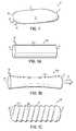
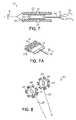
- FIG. 1is a perspective view of a muscle-energy converter.
- FIG. 1Ais a perspective view of a muscle-energy converter having an encasing block.
- FIG. 1Bis a perspective view of the converter of FIG. 1B in an extended condition.
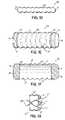
- FIG. 1Cis a perspective view of a muscle-energy converter having a corrugated encasing block.
- FIG. 1Dis a perspective view of the converter of FIG. 1C in an extended condition.
- FIG. 1Eis a perspective view of a muscle-energy converter having solid end blocks and an envelope containing a fluid.
- FIG. 1Fis a cross-sectional view of the converter of FIG. 1E .
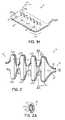
- FIG. 1Gis a partial schematic view of the mobile end of a muscle-energy converter having a fibrous connection to a muscle.
- FIG. 1His a partial view of the relatively stationary end of a muscle-energy converter.
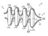
- FIG. 2is a perspective view of a muscle-energy converter having a set of steep serpentine springs.
- FIG. 2Ais a cross-sectional view taken along line 2 A- 2 A of FIG. 2 .
- FIG. 2Bis a schematic view of an exemplary tension member used with the converter of FIG. 2 .
- FIG. 3is a detailed view of an alternative embodiment of a muscle-energy converter at the point of contact between a tension member and an energy-processing unit.
- FIG. 3Ais a cross-sectional view of the embodiment of FIG. 3 .
- FIG. 4is a perspective view of an alternative embodiment of a muscle-energy converter.
- FIG. 5is a perspective view of an alternative embodiment of a muscle-energy converter similar to the embodiment of FIG. 4 .
- FIG. 6is a perspective view of an alternative embodiment of a muscle-energy converter including a muscle-coupling device.
- FIG. 10is a cross-sectional view of an alternative embodiment of a muscle-energy converter.
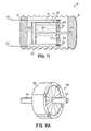
- FIG. 11Ais a partial perspective view of the embodiment of FIG. 11 .
- FIG. 12Bis a partial perspective view of an alternative embodiment of a tube section of the embodiment of FIG. 12 .
- FIG. 14Ais a partial elevation view of the tension spring of FIG. 14 in an extended condition.
- a converter 10is an elongated structure generally having a length and width similar to those of the tendon of a muscle (not shown) to which they are applied and a thickness not exceeding an order of magnitude greater than the thickness of the native tendon.
- Converter 10has a body 11 having a tissue-facing surface 13 , a mobile end 12 and a longitudinally opposed relatively stationary end 14 .
- One or more energy conduits 16protrude from the relatively stationary end 14 to conduct energy from the converter 10 to a power-consuming device (not shown) such as a circulatory device utilizing the energy from the converter 10 .
- Energy conduits 16may comprise, for example, electrical wires, hydraulic tubes, mechanical conduits such as a cable-in-sheath, or any other suitable mechanism.
- the mobile end 12 of the converter 10is connected to a muscle at a point proximate the musculotendinous junction.
- Methods of connecting the converter 10may for example include fiber-based tissue-interface devices such as those taught in U.S. Pat. No. 6,214,047, issued to Melvin, in conjunction with stress-distributing fiber termination devices such as those taught in U.S. Provisional Patent Application No. 60/642,016, the disclosures of which are incorporated by reference herein in their entirety.
- other methodsmay be used, including or not including removal of the tendon.
- an exemplary embodiment of a converter 10 cmay comprise an interface between active elements of the converter 10 c and surrounding tissue (not shown) in the form of an envelope 15 c having corrugations 17 and containing a fluid bath 19 such as a gel or oil.
- Envelope 15 cmay be made of an elastomeric material such as mold-cast silicone rubber, solution-cast polyurethane or any other suitable flexible material.
- Converter 10 cmay further comprise a mobile end 12 and a relatively stationary end 14 .
- Mobile and relatively stationary ends 12 , 14may comprise solid blocks 31 made of suitable materials having moduli in a relatively wide range.
- An exemplary embodiment of a converter 10 cmay, for example, comprise cast polyurethane elastomer blocks 31 for the mobile and relatively stationary ends 12 , 14 . Such blocks may be internally reinforced by fiber inclusion distributed and oriented to facilitate firm fixation to the active energy converting components of the converter 10 c , such as muscle coupling and solid tissue.
- An exemplary embodiment of converter 10 cmay further comprise a solution-cast polyurethane membrane envelope 15 c having transverse corrugations 17 that may be solution-bonded to the blocks 31 .
- an exemplary method of fixation of a muscle to the mobile end 12 of a converter 10may comprise fibers 37 that continue through the length of the converter 10 and are organized into cord-like tension elements 39 over such length.
- the interface of the mobile end 12 of the converter 10 with the musclecomprises only the continuing fibers 37 and the encasing block 15 c .
- a similar configurationis contemplated with a converter not having an encasing block 15 c .
- a converter 10 having a mobile end 12 and a relatively stationary end 14may comprise a rigid or semi rigid fixating structure 43 that is securely fixed to the active, energy-converting elements (not shown) of converter 10 by any suitable methods such as those described above for fixation of the mobile end 12 .
- the material and construction of the fixating structure 43may be such that it provides a sufficiently strong interface for fixation of energy-converting elements to fixating structure 43 and for fixation of fixating structure 43 to a skeleton or another converter.
- the fixating structure 43may alternatively facilitate coupling to one or more other converters 10 .
- Such couplingmay comprise suitable methods or components that provide a smooth profile and include biocompatible materials.
- Components to facilitate such couplingmay, for example, include screws, rivets, or self-locking colletts.
- fixation of the relatively stationary end 14may be facilitated by a circumferential surface suitable for fixation by binding, adhesives, or other suitable alternatives.
- an exemplary converter 18comprises a movable end 12 , a relatively stationary end 14 and at least one pair of non-rigid tension elements 20 , 20 ′ in a steep serpentine pattern such as a sinusoidal pattern with wave-length/full-wave-amplitude ratio generally in the range of about 0.5 to about 1.0.
- Converter 18may further comprise a corrugated elongated elastomeric envelope (not shown) filled with a liquid bath (not shown) comprising, for example, an oil or gel.
- Tension members 20 , 20 ′may, for example, lie in the same plane and be 180 degrees out of phase with respect to each other.
- Converter 18may further comprise energy processing units 22 and closed bands 24 .
- the tension members 20 , 20 ′may comprise flexurally stiff structures, such as stainless steel or titanium wires in the form of serpentine springs, or essentially flaccid elements such as cables. When tension members 20 , 20 ′ comprise flaccid elements, their shape may be maintained by the constraining effect of both the fixation members such as closed bands 24 and the energy processing units 22 , both to be described below.
- other materials and structures defining tension members 20 , 20 ′may be chosen to meet the requirements for strength, fatigue behavior, and elastic stiffness, both in flexion and elongation.
- a specific design of the tension elements 20 , 20 ′may also be chosen to correspond to desired specific levels of strain energy to be stored in each cycle and the required amount of tensile preload for subsequent muscle actuation.
- an exemplary embodiment of a tension member 20 acomprises a high-durometer elastomeric rod 21 a wrapped by a helical structure 21 b made, for example, of stainless steel, titanium, or other biocompatible metal and then formed into a serpentine pattern in accordance with requirements of the particular converter being designed.
- the helical structure 21 bmay be preformed and injected with resin and a catalyst to polymerize the elastomeric rod in situ.
- Tension member 20 amay further comprise a central high-strength fiber core 21 c made, for example, of linearly crystalline polyethylene fibers such as Spectra®, in order to increase the longitudinal stiffness while maintaining flexural stiffness of tension member 21 a .
- the construction of tension member 21 a as describedmay be considerably less stiff to traction or to bending than a non-helical wire structure, and may advantageously present a broader contact surface for cyclic compression of the energy processing units 22 .
- the tension members 20 , 20 ′ of this exemplary embodimentare securely held together at locations of proximity therebetween, such as locations corresponding to sinusoidal points at 90, 450, 810, 1170, and 1530 degrees for tension element 20 and corresponding sinusoidal points at 270, 630, 990, 1350 and 1710 degrees for tension element 20 ′.
- Securing of tension members 20 , 20 ′may be exemplarily achieved by closed bands 24 .
- each of the closed bands 24is a generally elliptical member comprising an internal bearing surface 25 .
- Closed bands 24may be of a suitable material such as one similar to the material of which tension members 20 , 20 ′ are made and capable of securing, for example, tension elements 20 , 20 ′ made of stainless steel wire or titanium wire.
- the internal bearing surface 25may comprise, for example, a hard polished ceramic or jewel-grade crystalline carbon such as industrial diamond.
- a plurality of schematically depicted generally elongated energy processing units 22are disposed between the tension members 20 , 20 ′, for example, at points 25 a , where tension members 20 , 20 ′ are farthest away from each other.
- the energy processing units 22may comprise an assembly of embedded piezoelectric devices and mechanical stabilizing components. In operation, and due to their position with respect to tension members 20 , 20 ′, the energy processing units 22 are compressed when tension is applied on the tension members 20 , 20 ′. Energy processing units 22 convert energy arising from their compression to a readily transferable form of energy.
- Each energy-processing unit 22may comprise an assembly of piezoelectric elements (not shown) such as crystals, electrodes, insulating layers and coverings, and structural members to deliver the compressive force applied by the tension members as a distributed compressive force on the surface of piezoelectric elements.
- Energy-processing units 22may further comprise mechanical members to stabilize the energy-processing units against columnar buckling in cases where their design carries a high aspect ratio.
- the output of the energy-processing units 22is in the form of electrical energy.
- tensile forcei.e., traction
- the elongation of the tension members 20 , 20 ′biases the points 25 a inwardly.
- This motion of points 25 ais of relatively low amplitude but produces a corresponding compressive force of relatively large magnitude against the ends of the energy-processing units 22 , with an associated energy that is in turn converted by the piezoelectric elements into electrical energy.
- Electrical energy collected from each of the energy processing units 22 in the converter 10may then be delivered by efferent transmission lines to the energy-consuming target device, via a circuit that may include energy storage and control components.
- an alternative embodiment of a converter 26 similar to converter 18 of FIGS. 2-2Acomprises tension members 20 , 20 ′ contacting hydraulic energy-processing units 28 at points 25 a .
- Each hydraulic energy-processing unitmay include a serpentine tube 23 and a compression plate 29 .
- Each end of a hydraulic energy-processing unit 28may comprise a groove 27 adapted to fully receive a serpentine tube 23 , at least partially receive a tension member 20 , 20 ′, and fully receive a compression plate 29 therebetween.
- Hydraulic energy-processing units 28may generally comprise a non-compressible block made, for example, of a ceramic material.
- Converter 26may further comprise a corrugated elongated elastomeric envelope (not shown) filled with a liquid bath (not shown) comprising, for example, an oil or gel.
- an alternative embodiment of a converter 30is similar to converter 18 ( FIG. 2 ) but it includes a different arrangement of tension members such as tension members 32 a, b, c, d of FIG. 4 .
- Each pair of tension members 32 a, b, c, dcomprises 180-degree out-of-phase serpentine tension members lying in adjacent parallel planes, such that the paths of the two tension members 32 a, b , or 32 c, d in any given pair cross at each half-wave length point.
- FIG. 4-5in which like reference numerals refer to like features in FIG. 2 , an alternative embodiment of a converter 30 is similar to converter 18 ( FIG. 2 ) but it includes a different arrangement of tension members such as tension members 32 a, b, c, d of FIG. 4 .
- Each pair of tension members 32 a, b, c, dcomprises 180-degree out-of-phase serpentine tension members lying in adjacent parallel planes, such that the paths of the two tension members 32 a,
- the path of tension member 32 abegins at the central axis of the converter 30 at 0 degrees, while tension member 32 b follows a path that begins at the central axis at 180 degrees.
- Tension members 32 a, bmay cross again at points respectively corresponding to 180 degrees for the tension member 32 a and 360 degrees for tension member 32 b , at 360 degrees for the tension member 32 a and 540 degrees for the tension member 32 b and at 540 degrees for the tension member 32 a and 720 degrees for the tension member 32 b.
- the energy processing units 22are disposed such that they are compressed by the two tension members 32 a, b in a pair at points every 180 degrees of the respective paths of tension elements 32 a, b .
- energy processing units 22may be disposed at points corresponding to the 90 degree point of the tension member 32 a and the 270 degree point of tension member 32 b , the 270 degree point of the tension member 32 a and the 450 degree point of tension member 32 b , and so on.
- the energy processing units 22may be identical to those described in the embodiment of FIG. 2 and their operation may follow the same principles as those in the embodiment of FIG. 2 .
- Converter 30may further comprise a corrugated elongated elastomeric envelope (not shown) filled with a liquid bath (not shown) comprising, for example, an oil or gel.
- an exemplary embodiment in accordance with the principles of the embodiment of FIG. 4includes a symmetric phasic pattern of tension members 32 a, b, c, d that may be used when converter 30 comprises more than one pair of tension members.
- the arrangement of tension members 32 a, b, c, d of FIGS. 4-5may lessen the tendency of converter 30 to torque, due to the symmetry of forces (symbolized by arrows 38 ) applied to the tension members 32 a, b, c, d arranged as shown in FIGS. 4-5 .
- Progressing from one end of the converter 30 to the other, paths of tension memberswould be in parallel planes 36 in a symmetrical pattern from one end to the other.
- converter 30 in the embodiments of FIGS. 4-5has been described as comprising energy-processing units 22 having piezoelectric elements, persons of ordinary skill in the art will appreciate that, alternatively, converter 30 may comprise hydraulic energy-processing units such as the energy processing units 28 in the embodiment of FIGS. 3-3A .
- Converter 30may further comprise a corrugated elongated elastomeric envelope (not shown) filled with a liquid bath (not shown) comprising, for example, an oil or gel.
- converters 18 , 20 , 26 , 30may be alternatively constructed as depicted, having a wafer-type muscle-coupling device 40 affixed to the converter.
- Muscle-coupling device 40may comprise an enveloping assembly 41 and a plurality of fine fibers 42 projecting therefrom and made, for example, of polymer, metal, or other suitable material, as described in U.S. Provisional Patent Application No. 60/642,016.
- Envelope assembly 41may be rigid or semi-rigid and may be made, for example, of a biocompatible metal such as titanium or a biocompatible fiber-matrix composite such as carbon-fiber epoxy, suitable for hard tissue fixation.
- the fibers 42extend from the muscle-coupling device 40 into the converter.
- fibersmay be organized into an even number of parallel bundles or tows, and each bundle may be impregnated with an elastomeric material and wound with a titanium or stainless steel spring-tempered helix to define tension members 44 .
- Fibers 42may exit the converter free of the elastomeric material, and be regrouped into bundles 46 of suitable size for passage into a muscle, and may further be fitted with needles 48 or the like adapted for muscle insertion as taught in U.S. Pat. No. 6,214,047.
- field coils 54may take on one or more of several specific mechanical arrangements of coil position, coil numbers, winding density, combinations of parallel and series connections, and core material if any (such as high-permeability material). Such arrangements may further be optimized by computer modeling of electromagnetic fields.
- Converter 50may further comprise a corrugated elongated elastomeric envelope (not shown) filled with a liquid bath (not shown) comprising, for example, an oil or gel.
- a flexible cord or cable 56affixes the magnet 52 to the mobile end of the converter 50 .
- the cable 56may pass through spacers (not shown) within corrugations from the magnet 52 to the mobile end 12 of the converter 50 .
- Materials for the cable and spacersmay be chosen based on demonstrated long-term and high-cycle durability under similar loads and lubrication.
- the cable 56may comprise titanium or stainless steel while the spacers may comprise machined ultra-high molecular weight polyurethane blocks.
- the arrangement herein describedmay allow shortening to occur over the entire length of a membranous corrugated envelope (if present), distributing strain over the entire corrugated length, while the magnet/coil displacement is located only at one end of that space. Only the magnet/coil segment of the space may need to be rigid or non-bending.
- a first energy conduit 76fluidly communicates the interior cavity 75 with the relatively stationary end 14 of the converter 70 and may comprise one or more flexible, very low compliance tubes adapted to transmit relatively high pressures, such as pressures in the range of several atmospheres.
- a second energy conduit 78fluidly communicates the relatively stationary end 14 with the interior portion of the converter 70 surrounding the cylinders 74 .
- FIG. 10depicts a converter 85 having a single rod 86 connected to a power-consuming device (not shown), persons skilled in the art will appreciate that converter 85 may alternatively comprise more than one rod 86 and/or more than one cable 92 .
- a turbine 100may be affixed to the cylinder and lie concentrically with the piston 102 such that the turbine 100 surrounds the piston rod 104 proximate the base 107 of the cylinder 98 .
- Permanent magnets 106may be coupled to the circumferential surfaces of the turbine 100 and indirectly (through a wall 101 defining cylinder 98 ) face a plurality of field magnets 108 in a suitable configuration such as a ring configuration affixed to the outer surface of cylinder 98 .
- Wall 101may be made of a non-magnetic material such as a polymer composite, a non-magnetic metal or any suitable material to permit interaction between permanent magnets 106 and field magnets 108 .
- Electrical energy conduits 103may be operatively connected to field magnets 108 and generally extend through the relatively stationary end 14 to communicate the converter 96 with a power-consuming device (not shown).
- contraction of a muscle connected to the mobile end 12 of converter 96may cause relative sliding motion between the piston 102 and the cylinder 98 , such that fluid filling the cavity 99 is expelled from the cylinder through turbine 100 , thereby causing rotation of the turbine 100 .
- Rotation of the turbine 100may cause rotation of the permanent magnets 106 coupled to the circumferential surfaces of the turbine 100 , which interact with field magnets 108 to induce electrical energy to flow from field magnets 108 through energy conduits 103 .
- an alternative embodiment of a converter 110may comprise a mobile end 12 , a relatively stationary end 14 and a plurality of serially connected hydraulic tubes 112 therebetween, each having first and second ends 113 , 117 .
- the mobile end 12may be connected to a contracting, paced skeletal muscle while the relatively stationary end 14 may be connected to a skeletally fixed anchor or to an opposing muscle connection.
- Each hydraulic tube 112may comprise an elastomer that may further be corrugated.
- the walls 115 defining hydraulic tubes 112may comprise a plurality of relatively nonexpansile longitudinally oriented fibers 114 and relatively nonexpansile circumferentially oriented fibers 116 .
- FIG. 12Banother embodiment of a hydraulic tube 112 a similar to and following the same principles as the embodiment of FIGS. 12-12A replaces the plurality of longitudinally oriented fibers 114 of hydraulic tubes 112 with respective flexible bands or ribbons 118 .
- Ribbons 118may comprise a suitable construction and materials taking into consideration, for example, the maximum expected bending stress, reasonable engineering safety factors, risk of fatigue and the failure limit of the material defining the ribbons 118 .
- tubes 112may take the form of modified and bent elongated metal bellows (not shown), having the inner curvature portion 111 restricted by suitable methods or components.
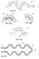
- an exemplary serpentine spring 120may extend parallelly with the tension members of a converter such as the converters 18 , 26 , 30 , 40 ( FIGS. 2 , 3 , 4 , 6 ).
- the spring 120is shown in both a compressed condition ( FIG. 14 ) and an extended condition ( FIG. 14A ) resulting from action of an applied tensile force depicted by arrow 124 .
- the spring constant and length of spring 120may be chosen in accordance with the particular muscle being harnessed.
- the strain energy stored in the spring from compression of the converter, as described above,may affect the available amount of preload of the converter carrying spring 120 . Preload is the state of elongation of a muscle secondary to applied tension before a contraction, whether such contraction results from spontaneous nerve impulse or from electrical pacing to a nerve or the muscle.
- spring 120is depicted as a conventional tension spring, persons skilled in the art will appreciate that any other suitable configuration may be used, such those comprising a helical tension spring, a helical compression spring, a torsion spring or a corrugated band.
- an exemplary helical tension spring 126formed from a suitable wire 128 , may partially define a converter such as converters 10 , 50 , 60 , 70 , 85 , 96 ( FIGS. 1 , 7 - 11 ), all of which may have respective patterns of corrugations on their respective outer surfaces.
- a convertersuch as converters 10 , 50 , 60 , 70 , 85 , 96 ( FIGS. 1 , 7 - 11 ), all of which may have respective patterns of corrugations on their respective outer surfaces.
- Considerations for choice of material and design for the helical tension springare the same as those described above for spring 120 ( FIGS. 14-14A ).
- the technical effect of spring 126 on a converter carrying itis also similar to that described above for spring 120 .
Landscapes
- Engineering & Computer Science (AREA)
- Power Engineering (AREA)
- Health & Medical Sciences (AREA)
- Life Sciences & Earth Sciences (AREA)
- Molecular Biology (AREA)
- Biomedical Technology (AREA)
- Nuclear Medicine, Radiotherapy & Molecular Imaging (AREA)
- Radiology & Medical Imaging (AREA)
- Animal Behavior & Ethology (AREA)
- General Health & Medical Sciences (AREA)
- Public Health (AREA)
- Veterinary Medicine (AREA)
- Prostheses (AREA)
Abstract
Description
Claims (10)
Priority Applications (1)
| Application Number | Priority Date | Filing Date | Title |
|---|---|---|---|
| US11/550,653US7715918B2 (en) | 2005-10-18 | 2006-10-18 | Muscle energy converter with smooth continuous tissue interface |
Applications Claiming Priority (2)
| Application Number | Priority Date | Filing Date | Title |
|---|---|---|---|
| US72765005P | 2005-10-18 | 2005-10-18 | |
| US11/550,653US7715918B2 (en) | 2005-10-18 | 2006-10-18 | Muscle energy converter with smooth continuous tissue interface |
Publications (2)
| Publication Number | Publication Date |
|---|---|
| US20070088402A1 US20070088402A1 (en) | 2007-04-19 |
| US7715918B2true US7715918B2 (en) | 2010-05-11 |
Family
ID=37949127
Family Applications (1)
| Application Number | Title | Priority Date | Filing Date |
|---|---|---|---|
| US11/550,653Expired - Fee RelatedUS7715918B2 (en) | 2005-10-18 | 2006-10-18 | Muscle energy converter with smooth continuous tissue interface |
Country Status (1)
| Country | Link |
|---|---|
| US (1) | US7715918B2 (en) |
Cited By (21)
| Publication number | Priority date | Publication date | Assignee | Title |
|---|---|---|---|---|
| US20080278804A1 (en)* | 2007-01-22 | 2008-11-13 | Morteza Gharib | Method and apparatus for quantitative 3-D imaging |
| US20080278570A1 (en)* | 2007-04-23 | 2008-11-13 | Morteza Gharib | Single-lens, single-sensor 3-D imaging device with a central aperture for obtaining camera position |
| US20090131354A1 (en)* | 2007-05-22 | 2009-05-21 | Bader Andreas G | miR-126 REGULATED GENES AND PATHWAYS AS TARGETS FOR THERAPEUTIC INTERVENTION |
| US20090152990A1 (en)* | 2007-12-07 | 2009-06-18 | Veryst Engineering Llc | Apparatus for in vivo energy harvesting |
| US20090295908A1 (en)* | 2008-01-22 | 2009-12-03 | Morteza Gharib | Method and device for high-resolution three-dimensional imaging which obtains camera pose using defocusing |
| US20100141052A1 (en)* | 2008-12-04 | 2010-06-10 | Searete Llc,A Limited Liability Corporation Of The State Of Delaware | System for powering devices from intraluminal pressure changes |
| US20100140959A1 (en)* | 2008-12-04 | 2010-06-10 | Searete Llc, A Limited Liability Corporation Of The State Of Delaware | Device and system for generation of power from intraluminal pressure changes |
| US20100140958A1 (en)* | 2008-12-04 | 2010-06-10 | Searete Llc, A Limited Liability Corporation Of The State Of Delaware | Method for powering devices from intraluminal pressure changes |
| US20100140956A1 (en)* | 2008-12-04 | 2010-06-10 | Searete Llc. | Method for generation of power from intraluminal pressure changes |
| US20100140957A1 (en)* | 2008-12-04 | 2010-06-10 | Searete Llc | Method for generation of power from intraluminal pressure changes |
| US20100140943A1 (en)* | 2008-12-04 | 2010-06-10 | Searete Llc, A Limited Liability Corporation Of The State Of Delaware | Device for storage of intraluminally generated power |
| US20100298935A1 (en)* | 2007-09-12 | 2010-11-25 | Surgical Energetics, Inc. | Medical Device and Tension Member for Use in a Subject |
| US20110004053A1 (en)* | 2007-12-05 | 2011-01-06 | Surgical Energetics, Inc. | bolster for securing a septal splint to a cardiac wall, a method of use thereof, and a system including the same |
| US20110037832A1 (en)* | 2009-08-11 | 2011-02-17 | California Institute Of Technology | Defocusing Feature Matching System to Measure Camera Pose with Interchangeable Lens Cameras |
| US20110074932A1 (en)* | 2009-08-27 | 2011-03-31 | California Institute Of Technology | Accurate 3D Object Reconstruction Using a Handheld Device with a Projected Light Pattern |
| US8456645B2 (en) | 2007-01-22 | 2013-06-04 | California Institute Of Technology | Method and system for fast three-dimensional imaging using defocusing and feature recognition |
| US20140018918A1 (en)* | 2011-01-17 | 2014-01-16 | Jiangning Wang | Muscle Prosthesis with Suspension Fixing Apparatus for Implantation in Human Body and Production Method Thereof |
| US9084859B2 (en) | 2011-03-14 | 2015-07-21 | Sleepnea Llc | Energy-harvesting respiratory method and device |
| US10182223B2 (en) | 2010-09-03 | 2019-01-15 | California Institute Of Technology | Three-dimensional imaging system |
| US11406264B2 (en) | 2016-01-25 | 2022-08-09 | California Institute Of Technology | Non-invasive measurement of intraocular pressure |
| US20230369996A1 (en)* | 2022-05-15 | 2023-11-16 | Timm A. Vanderelli | Implantable Power Generator |
Families Citing this family (10)
| Publication number | Priority date | Publication date | Assignee | Title |
|---|---|---|---|---|
| US7625404B2 (en)* | 2005-12-24 | 2009-12-01 | Mohsen Shahinpoor | Surgical correction of ptosis by polymeric artificial muscles |
| US20080200963A1 (en)* | 2007-02-15 | 2008-08-21 | Benjamin Pless | Implantable power generator |
| GB2448506A (en)* | 2007-04-17 | 2008-10-22 | Perpetuum Ltd | Implanted energy harvester with hydraulically driven linear generator for powering a further implanted device |
| WO2009108705A1 (en)* | 2008-02-25 | 2009-09-03 | Autonomic Technologies, Inc. | Devices, methods, and systems for harvesting energy in the body |
| US8283793B2 (en)* | 2008-08-21 | 2012-10-09 | Autonomic Technologies, Inc. | Device for energy harvesting within a vessel |
| WO2010030700A1 (en) | 2008-09-09 | 2010-03-18 | Incube Labs, Llc | Energy harvesting mechanism |
| US9026212B2 (en)* | 2008-09-23 | 2015-05-05 | Incube Labs, Llc | Energy harvesting mechanism for medical devices |
| US10799076B2 (en)* | 2015-11-25 | 2020-10-13 | Simply Innovative LLC | Devices for preventing towel slippage |
| ITUA20161624A1 (en)* | 2016-03-14 | 2017-09-14 | Fabiana Botea | ELECTROMAGNETIC INDUCTION DEVICE FOR KINETIC ENERGY TRANSFORMATION IN ELECTRICAL ENERGY. |
| US10299615B1 (en)* | 2018-07-31 | 2019-05-28 | Stephen P. Donegan | Hanger spacer tape |
Citations (117)
| Publication number | Priority date | Publication date | Assignee | Title |
|---|---|---|---|---|
| US2826193A (en) | 1956-08-01 | 1958-03-11 | Vineberg Heart Foundation | Cardiac resuscitation device |
| US3053249A (en) | 1959-08-25 | 1962-09-11 | Gorman Rupp Ind Inc | Cardiac massage apparatus |
| US3176316A (en) | 1963-01-07 | 1965-04-06 | Bruce R Bodell | Plastic prosthetic tendon |
| US3455298A (en) | 1967-04-10 | 1969-07-15 | George L Anstadt | Instrument for direct mechanical cardiac massage |
| US3513836A (en) | 1966-09-05 | 1970-05-26 | Andre Sausse | Prosthesis for cardiac assistance |
| US3590815A (en) | 1969-01-07 | 1971-07-06 | Peter Shiff | Portable mechanical ventricular assistance device |
| US3595230A (en) | 1968-07-25 | 1971-07-27 | Abbott Lab | Intravenous catheter placement unit with tubular guide sheath |
| US3613672A (en) | 1969-07-09 | 1971-10-19 | Peter Schiff | Mechanical ventricular assistance cup |
| US3659615A (en)* | 1970-06-08 | 1972-05-02 | Carl C Enger | Encapsulated non-permeable piezoelectric powered pacesetter |
| US3668708A (en) | 1969-12-23 | 1972-06-13 | North American Rockwell | Artificial heart |
| US3713439A (en) | 1970-03-02 | 1973-01-30 | J Cabezudo | Massage envelope belt with adjusting dispositives for vibrators and mobilizers |
| US3725984A (en) | 1970-09-02 | 1973-04-10 | A Graber | Process and apparatus for the manufacture of pile fabrics |
| US3791388A (en) | 1971-09-22 | 1974-02-12 | Ethicon Inc | Covered suture |
| US3827426A (en) | 1971-07-16 | 1974-08-06 | P Sawyer | Prosthetic pump |
| US3835864A (en) | 1970-09-21 | 1974-09-17 | Rasor Ass Inc | Intra-cardiac stimulator |
| US3983863A (en) | 1975-06-02 | 1976-10-05 | American Hospital Supply Corporation | Heart support for coronary artery surgery |
| US4149277A (en) | 1977-06-22 | 1979-04-17 | General Atomic Company | Artificial tendon prostheses |
| US4187558A (en) | 1977-10-25 | 1980-02-12 | Cutter Laboratories, Inc. | Prosthetic ligament |
| US4192293A (en) | 1978-09-05 | 1980-03-11 | Manfred Asrican | Cardiac assist device |
| US4255820A (en) | 1979-07-24 | 1981-03-17 | Rothermel Joel E | Artificial ligaments |
| US4345601A (en) | 1980-04-07 | 1982-08-24 | Mamoru Fukuda | Continuous suturing device |
| US4453537A (en) | 1981-08-04 | 1984-06-12 | Spitzer Daniel E | Apparatus for powering a body implant device |
| US4519392A (en) | 1982-10-12 | 1985-05-28 | Lingua Robert W | Hemostasing muscle clips for needleless surgery |
| US4536893A (en) | 1982-03-03 | 1985-08-27 | Roberto Parravicini | Implant device for substaining the activity of the myocardium |
| US4585458A (en) | 1981-06-10 | 1986-04-29 | Kurland Kenneth Z | Means and method of implanting bioprosthetics |
| US4597766A (en) | 1984-10-26 | 1986-07-01 | American Hospital Supply Corporation | Implantable bioprosthetic tendons and ligaments |
| US4621617A (en) | 1981-06-29 | 1986-11-11 | Sharma Devendra N | Electro-magnetically controlled artificial heart device for compressing cardiac muscle |
| US4690134A (en) | 1985-07-01 | 1987-09-01 | Snyders Robert V | Ventricular assist device |
| US4713075A (en) | 1981-06-10 | 1987-12-15 | Kurland Kenneth Z | Method for the repair of connective tissue |
| US4773910A (en) | 1987-08-17 | 1988-09-27 | Johnson & Johnson Consumer Products, Inc. | Permanent ligament prosthesis |
| US4809676A (en) | 1987-12-28 | 1989-03-07 | Freeman Maynard L | Heart assist device and method of implanting it |
| US4846831A (en) | 1988-04-27 | 1989-07-11 | Skillin David E | Manual back-up drive for artificial heart |
| US4904255A (en) | 1985-12-16 | 1990-02-27 | Aerospatiale Societe Nationale Industrielle | Complete artificial heart with two pumping modules connected together by a functional connection |
| US4917700A (en) | 1988-08-01 | 1990-04-17 | Zimmer, Inc. | Prosthetic ligament |
| US4936857A (en) | 1987-02-23 | 1990-06-26 | Kulik Yaroslav P | Prosthetic pericardium |
| US4946377A (en) | 1989-11-06 | 1990-08-07 | W. L. Gore & Associates, Inc. | Tissue repair device |
| US4957477A (en) | 1986-05-22 | 1990-09-18 | Astra Tech Ab | Heart assist jacket and method of using it |
| US4964414A (en) | 1987-08-27 | 1990-10-23 | Yasunobu Handa | Electrode for use in implanting in a living body |
| US5013304A (en) | 1989-02-22 | 1991-05-07 | Bfd, Inc. | Intravascular catheter assembly |
| US5049155A (en) | 1982-09-10 | 1991-09-17 | W. L. Gore & Associates, Inc. | Prosthesis for tensile-load-carrying tissue and method of manufacture |
| US5061283A (en) | 1987-10-30 | 1991-10-29 | Pfizer Hospital Products Group, Inc. | Method for tendon and ligament repair |
| US5109843A (en) | 1990-11-30 | 1992-05-05 | University Of Cincinnati | Extra to-intracorporeal power supply |
| US5116372A (en) | 1986-05-07 | 1992-05-26 | Laboureau Jacques Philippe | Artificial ligament in synthetic materials impregnated and coated with elastic resin and its coating procedure |
| US5119804A (en) | 1990-11-19 | 1992-06-09 | Anstadt George L | Heart massage apparatus |
| US5131905A (en) | 1990-07-16 | 1992-07-21 | Grooters Ronald K | External cardiac assist device |
| US5139517A (en) | 1989-11-08 | 1992-08-18 | Corral David F | Orthotopic intraventricular heart pump |
| US5169381A (en) | 1991-03-29 | 1992-12-08 | Snyders Robert V | Ventricular assist device |
| US5192314A (en) | 1991-12-12 | 1993-03-09 | Daskalakis Michael K | Synthetic intraventricular implants and method of inserting |
| US5197983A (en) | 1988-04-19 | 1993-03-30 | W. L. Gore & Associates, Inc. | Ligament and tendon prosthesis |
| US5201880A (en) | 1992-01-27 | 1993-04-13 | Pioneering Technologies, Inc. | Mitral and tricuspid annuloplasty rings |
| US5217495A (en) | 1989-05-10 | 1993-06-08 | United States Surgical Corporation | Synthetic semiabsorbable composite yarn |
| US5256132A (en) | 1992-08-17 | 1993-10-26 | Snyders Robert V | Cardiac assist envelope for endoscopic application |
| US5258021A (en) | 1992-01-27 | 1993-11-02 | Duran Carlos G | Sigmoid valve annuloplasty ring |
| US5334217A (en) | 1992-01-21 | 1994-08-02 | Regents Of The University Of Minnesota | Septal defect closure device |
| US5345949A (en) | 1992-09-02 | 1994-09-13 | Shlain Leonard M | Methods for use in surgical gastroplastic procedure |
| US5358519A (en) | 1989-12-06 | 1994-10-25 | Medtronic, Inc. | Muscle control and monitoring system |
| US5366459A (en) | 1987-05-14 | 1994-11-22 | Inbae Yoon | Surgical clip and clip application procedures |
| US5370685A (en) | 1991-07-16 | 1994-12-06 | Stanford Surgical Technologies, Inc. | Endovascular aortic valve replacement |
| US5383840A (en) | 1992-07-28 | 1995-01-24 | Vascor, Inc. | Biocompatible ventricular assist and arrhythmia control device including cardiac compression band-stay-pad assembly |
| US5385528A (en) | 1993-06-17 | 1995-01-31 | Wilk; Peter J. | Intrapericardial assist device and associated method |
| US5409499A (en) | 1993-06-18 | 1995-04-25 | Ethicon, Inc. | Biocompatible suture knot clip |
| US5411481A (en) | 1992-04-08 | 1995-05-02 | American Cyanamid Co. | Surgical purse string suturing instrument and method |
| US5417683A (en) | 1994-07-13 | 1995-05-23 | Shiao; I-Shen | Mini-graft hair implanting device for implanting multiple clumps of hair follicles at one time |
| US5443504A (en)* | 1991-09-30 | 1995-08-22 | Hill; John D. | Basic skeletal muscle energy conversion system |
| US5456715A (en) | 1993-05-21 | 1995-10-10 | Liotta; Domingo S. | Implantable mechanical system for assisting blood circulation |
| US5479946A (en)* | 1994-04-15 | 1996-01-02 | Allegheny-Singer Research Institute | Muscle energy converter |
| US5484391A (en) | 1992-07-30 | 1996-01-16 | Univ Temple | Direct manual cardiac compression method |
| US5487760A (en) | 1994-03-08 | 1996-01-30 | Ats Medical, Inc. | Heart valve prosthesis incorporating electronic sensing, monitoring and/or pacing circuitry |
| US5533958A (en) | 1993-06-17 | 1996-07-09 | Wilk; Peter J. | Intrapericardial assist device and associated method |
| US5540705A (en) | 1995-05-19 | 1996-07-30 | Suturtek, Inc. | Suturing instrument with thread management |
| US5571176A (en) | 1993-04-02 | 1996-11-05 | Taheri; Syde A. | Partially autogenous four chambered heart |
| US5584840A (en) | 1995-09-05 | 1996-12-17 | Ramsey; James E. | Umbilical cord cutting and clamping device |
| US5593424A (en) | 1994-08-10 | 1997-01-14 | Segmed, Inc. | Apparatus and method for reducing and stabilizing the circumference of a vascular structure |
| US5620452A (en) | 1994-12-22 | 1997-04-15 | Yoon; Inbae | Surgical clip with ductile tissue penetrating members |
| US5643308A (en) | 1995-02-28 | 1997-07-01 | Markman; Barry Stephen | Method and apparatus for forming multiple cavities for placement of hair grafts |
| US5655548A (en) | 1996-09-16 | 1997-08-12 | Circulation, Inc. | Method for treatment of ischemic heart disease by providing transvenous myocardial perfusion |
| US5667526A (en) | 1995-09-07 | 1997-09-16 | Levin; John M. | Tissue retaining clamp |
| US5697978A (en) | 1994-12-30 | 1997-12-16 | Sgro; Jean-Claude | Prosthetic element for the treatment of inguinal hernias, in particular by the celioscopic route |
| US5702343A (en) | 1996-10-02 | 1997-12-30 | Acorn Medical, Inc. | Cardiac reinforcement device |
| US5713954A (en) | 1995-06-13 | 1998-02-03 | Abiomed R&D, Inc. | Extra cardiac ventricular assist device |
| US5738627A (en) | 1994-08-18 | 1998-04-14 | Duke University | Bi-ventricular cardiac assist device |
| US5738626A (en) | 1996-06-14 | 1998-04-14 | Jarvik; Robert | Two-step cardiomyoplasty with ventricular reduction |
| US5749883A (en) | 1995-08-30 | 1998-05-12 | Halpern; David Marcos | Medical instrument |
| US5766250A (en) | 1996-10-28 | 1998-06-16 | Medicinelodge, Inc. | Ligament fixator for a ligament anchor system |
| US5797932A (en) | 1995-11-24 | 1998-08-25 | Jong-Deok Park | Muscle clamping device |
| US5800528A (en) | 1995-06-13 | 1998-09-01 | Abiomed R & D, Inc. | Passive girdle for heart ventricle for therapeutic aid to patients having ventricular dilatation |
| US5846255A (en) | 1996-01-31 | 1998-12-08 | Casey Medical Products Limited | Surgical clip |
| US5849019A (en) | 1995-03-09 | 1998-12-15 | Yoon; Inbae | Multifunctional spring clips and cartridges and applications therefor |
| US5910124A (en) | 1994-01-10 | 1999-06-08 | Cardiassist Incorporated | Ventricular assist device and method |
| US5957977A (en) | 1996-01-02 | 1999-09-28 | University Of Cincinnati | Activation device for the natural heart including internal and external support structures |
| US5961440A (en) | 1997-01-02 | 1999-10-05 | Myocor, Inc. | Heart wall tension reduction apparatus and method |
| US5981827A (en) | 1996-11-12 | 1999-11-09 | Regents Of The University Of California | Carbon based prosthetic devices |
| US6019722A (en) | 1997-09-17 | 2000-02-01 | Guidant Corporation | Device to permit offpump beating heart coronary bypass surgery |
| US6045497A (en) | 1997-01-02 | 2000-04-04 | Myocor, Inc. | Heart wall tension reduction apparatus and method |
| US6050936A (en) | 1997-01-02 | 2000-04-18 | Myocor, Inc. | Heart wall tension reduction apparatus |
| US6077214A (en) | 1998-07-29 | 2000-06-20 | Myocor, Inc. | Stress reduction apparatus and method |
| US6085754A (en) | 1998-07-13 | 2000-07-11 | Acorn Cardiovascular, Inc. | Cardiac disease treatment method |
| US6110100A (en) | 1998-04-22 | 2000-08-29 | Scimed Life Systems, Inc. | System for stress relieving the heart muscle and for controlling heart function |
| US6123662A (en) | 1998-07-13 | 2000-09-26 | Acorn Cardiovascular, Inc. | Cardiac disease treatment and device |
| US6125852A (en) | 1993-02-22 | 2000-10-03 | Heartport, Inc. | Minimally-invasive devices and methods for treatment of congestive heart failure |
| US6159224A (en) | 1996-11-27 | 2000-12-12 | Yoon; Inbae | Multiple needle suturing instrument and method |
| US6165186A (en) | 1997-12-18 | 2000-12-26 | Novare Surgical Systems, Inc. | Vascular clamps and surgical retractors with directional filaments for tissue engagement |
| US6170415B1 (en) | 1998-11-17 | 2001-01-09 | Brother Kogyo Kabushiki Kaisha | Sewing machine with multiple needles |
| US6179791B1 (en) | 1999-09-21 | 2001-01-30 | Acorn Cardiovascular, Inc. | Device for heart measurement |
| US6183411B1 (en) | 1998-09-21 | 2001-02-06 | Myocor, Inc. | External stress reduction device and method |
| US6214047B1 (en) | 1998-03-10 | 2001-04-10 | University Of Cincinnati | Article and method for coupling muscle to a prosthetic device |
| US6260552B1 (en) | 1998-07-29 | 2001-07-17 | Myocor, Inc. | Transventricular implant tools and devices |
| US6293906B1 (en) | 2000-01-14 | 2001-09-25 | Acorn Cardiovascular, Inc. | Delivery of cardiac constraint jacket |
| US6299621B1 (en) | 1999-06-18 | 2001-10-09 | Novare Surgical Systems, Inc. | Surgical clamp pads with elastomer impregnated mesh |
| US6319231B1 (en) | 1999-02-12 | 2001-11-20 | Abiomed, Inc. | Medical connector |
| US6324431B1 (en) | 1998-07-06 | 2001-11-27 | Abiomed, Inc. | Transcutaneous energy transfer device with magnetic field protected components in secondary coil |
| US6324430B1 (en) | 1998-07-06 | 2001-11-27 | Abiomed, Inc. | Magnetic shield for primary coil of transcutaneous energy transfer device |
| US6332893B1 (en) | 1997-12-17 | 2001-12-25 | Myocor, Inc. | Valve to myocardium tension members device and method |
| US6592619B2 (en) | 1996-01-02 | 2003-07-15 | University Of Cincinnati | Heart wall actuation device for the natural heart |
| US20050027332A1 (en)* | 2003-07-30 | 2005-02-03 | Zohar Avrahami | Implanted autonomic energy source |
| US6945926B2 (en)* | 2001-10-18 | 2005-09-20 | Allegheny-Singer Research Institute | Muscle energy converter |
| US7081084B2 (en) | 2002-07-16 | 2006-07-25 | University Of Cincinnati | Modular power system and method for a heart wall actuation system for the natural heart |
- 2006
- 2006-10-18USUS11/550,653patent/US7715918B2/ennot_activeExpired - Fee Related
Patent Citations (130)
| Publication number | Priority date | Publication date | Assignee | Title |
|---|---|---|---|---|
| US2826193A (en) | 1956-08-01 | 1958-03-11 | Vineberg Heart Foundation | Cardiac resuscitation device |
| US3053249A (en) | 1959-08-25 | 1962-09-11 | Gorman Rupp Ind Inc | Cardiac massage apparatus |
| US3176316A (en) | 1963-01-07 | 1965-04-06 | Bruce R Bodell | Plastic prosthetic tendon |
| US3513836A (en) | 1966-09-05 | 1970-05-26 | Andre Sausse | Prosthesis for cardiac assistance |
| US3455298A (en) | 1967-04-10 | 1969-07-15 | George L Anstadt | Instrument for direct mechanical cardiac massage |
| US3595230A (en) | 1968-07-25 | 1971-07-27 | Abbott Lab | Intravenous catheter placement unit with tubular guide sheath |
| US3590815A (en) | 1969-01-07 | 1971-07-06 | Peter Shiff | Portable mechanical ventricular assistance device |
| US3613672A (en) | 1969-07-09 | 1971-10-19 | Peter Schiff | Mechanical ventricular assistance cup |
| US3668708A (en) | 1969-12-23 | 1972-06-13 | North American Rockwell | Artificial heart |
| US3713439A (en) | 1970-03-02 | 1973-01-30 | J Cabezudo | Massage envelope belt with adjusting dispositives for vibrators and mobilizers |
| US3659615A (en)* | 1970-06-08 | 1972-05-02 | Carl C Enger | Encapsulated non-permeable piezoelectric powered pacesetter |
| US3725984A (en) | 1970-09-02 | 1973-04-10 | A Graber | Process and apparatus for the manufacture of pile fabrics |
| US3835864A (en) | 1970-09-21 | 1974-09-17 | Rasor Ass Inc | Intra-cardiac stimulator |
| US3827426A (en) | 1971-07-16 | 1974-08-06 | P Sawyer | Prosthetic pump |
| US3791388A (en) | 1971-09-22 | 1974-02-12 | Ethicon Inc | Covered suture |
| US3983863A (en) | 1975-06-02 | 1976-10-05 | American Hospital Supply Corporation | Heart support for coronary artery surgery |
| US4149277A (en) | 1977-06-22 | 1979-04-17 | General Atomic Company | Artificial tendon prostheses |
| US4187558A (en) | 1977-10-25 | 1980-02-12 | Cutter Laboratories, Inc. | Prosthetic ligament |
| US4192293A (en) | 1978-09-05 | 1980-03-11 | Manfred Asrican | Cardiac assist device |
| US4255820A (en) | 1979-07-24 | 1981-03-17 | Rothermel Joel E | Artificial ligaments |
| US4345601A (en) | 1980-04-07 | 1982-08-24 | Mamoru Fukuda | Continuous suturing device |
| US4585458A (en) | 1981-06-10 | 1986-04-29 | Kurland Kenneth Z | Means and method of implanting bioprosthetics |
| US4713075A (en) | 1981-06-10 | 1987-12-15 | Kurland Kenneth Z | Method for the repair of connective tissue |
| US4621617A (en) | 1981-06-29 | 1986-11-11 | Sharma Devendra N | Electro-magnetically controlled artificial heart device for compressing cardiac muscle |
| US4453537A (en) | 1981-08-04 | 1984-06-12 | Spitzer Daniel E | Apparatus for powering a body implant device |
| US4536893A (en) | 1982-03-03 | 1985-08-27 | Roberto Parravicini | Implant device for substaining the activity of the myocardium |
| US5049155A (en) | 1982-09-10 | 1991-09-17 | W. L. Gore & Associates, Inc. | Prosthesis for tensile-load-carrying tissue and method of manufacture |
| US4519392A (en) | 1982-10-12 | 1985-05-28 | Lingua Robert W | Hemostasing muscle clips for needleless surgery |
| US4597766A (en) | 1984-10-26 | 1986-07-01 | American Hospital Supply Corporation | Implantable bioprosthetic tendons and ligaments |
| US4690134A (en) | 1985-07-01 | 1987-09-01 | Snyders Robert V | Ventricular assist device |
| US4904255A (en) | 1985-12-16 | 1990-02-27 | Aerospatiale Societe Nationale Industrielle | Complete artificial heart with two pumping modules connected together by a functional connection |
| US5116372A (en) | 1986-05-07 | 1992-05-26 | Laboureau Jacques Philippe | Artificial ligament in synthetic materials impregnated and coated with elastic resin and its coating procedure |
| US4957477A (en) | 1986-05-22 | 1990-09-18 | Astra Tech Ab | Heart assist jacket and method of using it |
| US4936857A (en) | 1987-02-23 | 1990-06-26 | Kulik Yaroslav P | Prosthetic pericardium |
| US5366459A (en) | 1987-05-14 | 1994-11-22 | Inbae Yoon | Surgical clip and clip application procedures |
| US4773910A (en) | 1987-08-17 | 1988-09-27 | Johnson & Johnson Consumer Products, Inc. | Permanent ligament prosthesis |
| US4964414A (en) | 1987-08-27 | 1990-10-23 | Yasunobu Handa | Electrode for use in implanting in a living body |
| US5061283A (en) | 1987-10-30 | 1991-10-29 | Pfizer Hospital Products Group, Inc. | Method for tendon and ligament repair |
| US4809676A (en) | 1987-12-28 | 1989-03-07 | Freeman Maynard L | Heart assist device and method of implanting it |
| US5197983A (en) | 1988-04-19 | 1993-03-30 | W. L. Gore & Associates, Inc. | Ligament and tendon prosthesis |
| US4846831A (en) | 1988-04-27 | 1989-07-11 | Skillin David E | Manual back-up drive for artificial heart |
| US4917700A (en) | 1988-08-01 | 1990-04-17 | Zimmer, Inc. | Prosthetic ligament |
| US5013304A (en) | 1989-02-22 | 1991-05-07 | Bfd, Inc. | Intravascular catheter assembly |
| US5217495A (en) | 1989-05-10 | 1993-06-08 | United States Surgical Corporation | Synthetic semiabsorbable composite yarn |
| US4946377A (en) | 1989-11-06 | 1990-08-07 | W. L. Gore & Associates, Inc. | Tissue repair device |
| US5139517A (en) | 1989-11-08 | 1992-08-18 | Corral David F | Orthotopic intraventricular heart pump |
| US5358519A (en) | 1989-12-06 | 1994-10-25 | Medtronic, Inc. | Muscle control and monitoring system |
| US5131905A (en) | 1990-07-16 | 1992-07-21 | Grooters Ronald K | External cardiac assist device |
| US5119804A (en) | 1990-11-19 | 1992-06-09 | Anstadt George L | Heart massage apparatus |
| US5109843A (en) | 1990-11-30 | 1992-05-05 | University Of Cincinnati | Extra to-intracorporeal power supply |
| US5169381A (en) | 1991-03-29 | 1992-12-08 | Snyders Robert V | Ventricular assist device |
| US5370685A (en) | 1991-07-16 | 1994-12-06 | Stanford Surgical Technologies, Inc. | Endovascular aortic valve replacement |
| US5443504A (en)* | 1991-09-30 | 1995-08-22 | Hill; John D. | Basic skeletal muscle energy conversion system |
| US5192314A (en) | 1991-12-12 | 1993-03-09 | Daskalakis Michael K | Synthetic intraventricular implants and method of inserting |
| US5334217A (en) | 1992-01-21 | 1994-08-02 | Regents Of The University Of Minnesota | Septal defect closure device |
| US5258021A (en) | 1992-01-27 | 1993-11-02 | Duran Carlos G | Sigmoid valve annuloplasty ring |
| US5201880A (en) | 1992-01-27 | 1993-04-13 | Pioneering Technologies, Inc. | Mitral and tricuspid annuloplasty rings |
| US5411481A (en) | 1992-04-08 | 1995-05-02 | American Cyanamid Co. | Surgical purse string suturing instrument and method |
| US5383840A (en) | 1992-07-28 | 1995-01-24 | Vascor, Inc. | Biocompatible ventricular assist and arrhythmia control device including cardiac compression band-stay-pad assembly |
| US5484391A (en) | 1992-07-30 | 1996-01-16 | Univ Temple | Direct manual cardiac compression method |
| US5256132A (en) | 1992-08-17 | 1993-10-26 | Snyders Robert V | Cardiac assist envelope for endoscopic application |
| US5345949A (en) | 1992-09-02 | 1994-09-13 | Shlain Leonard M | Methods for use in surgical gastroplastic procedure |
| US6125852A (en) | 1993-02-22 | 2000-10-03 | Heartport, Inc. | Minimally-invasive devices and methods for treatment of congestive heart failure |
| US5571176A (en) | 1993-04-02 | 1996-11-05 | Taheri; Syde A. | Partially autogenous four chambered heart |
| US5456715A (en) | 1993-05-21 | 1995-10-10 | Liotta; Domingo S. | Implantable mechanical system for assisting blood circulation |
| US5533958A (en) | 1993-06-17 | 1996-07-09 | Wilk; Peter J. | Intrapericardial assist device and associated method |
| US5385528A (en) | 1993-06-17 | 1995-01-31 | Wilk; Peter J. | Intrapericardial assist device and associated method |
| US5409499A (en) | 1993-06-18 | 1995-04-25 | Ethicon, Inc. | Biocompatible suture knot clip |
| US5910124A (en) | 1994-01-10 | 1999-06-08 | Cardiassist Incorporated | Ventricular assist device and method |
| US5487760A (en) | 1994-03-08 | 1996-01-30 | Ats Medical, Inc. | Heart valve prosthesis incorporating electronic sensing, monitoring and/or pacing circuitry |
| US5479946A (en)* | 1994-04-15 | 1996-01-02 | Allegheny-Singer Research Institute | Muscle energy converter |
| US5417683A (en) | 1994-07-13 | 1995-05-23 | Shiao; I-Shen | Mini-graft hair implanting device for implanting multiple clumps of hair follicles at one time |
| US5709695A (en) | 1994-08-10 | 1998-01-20 | Segmed, Inc. | Apparatus for reducing the circumference of a vascular structure |
| US5593424A (en) | 1994-08-10 | 1997-01-14 | Segmed, Inc. | Apparatus and method for reducing and stabilizing the circumference of a vascular structure |
| US5738627A (en) | 1994-08-18 | 1998-04-14 | Duke University | Bi-ventricular cardiac assist device |
| US5620452A (en) | 1994-12-22 | 1997-04-15 | Yoon; Inbae | Surgical clip with ductile tissue penetrating members |
| US5697978A (en) | 1994-12-30 | 1997-12-16 | Sgro; Jean-Claude | Prosthetic element for the treatment of inguinal hernias, in particular by the celioscopic route |
| US5643308A (en) | 1995-02-28 | 1997-07-01 | Markman; Barry Stephen | Method and apparatus for forming multiple cavities for placement of hair grafts |
| US5849019A (en) | 1995-03-09 | 1998-12-15 | Yoon; Inbae | Multifunctional spring clips and cartridges and applications therefor |
| US5540705A (en) | 1995-05-19 | 1996-07-30 | Suturtek, Inc. | Suturing instrument with thread management |
| US5800528A (en) | 1995-06-13 | 1998-09-01 | Abiomed R & D, Inc. | Passive girdle for heart ventricle for therapeutic aid to patients having ventricular dilatation |
| US5713954A (en) | 1995-06-13 | 1998-02-03 | Abiomed R&D, Inc. | Extra cardiac ventricular assist device |
| US5749883A (en) | 1995-08-30 | 1998-05-12 | Halpern; David Marcos | Medical instrument |
| US5584840A (en) | 1995-09-05 | 1996-12-17 | Ramsey; James E. | Umbilical cord cutting and clamping device |
| US5667526A (en) | 1995-09-07 | 1997-09-16 | Levin; John M. | Tissue retaining clamp |
| US5797932A (en) | 1995-11-24 | 1998-08-25 | Jong-Deok Park | Muscle clamping device |
| US5957977A (en) | 1996-01-02 | 1999-09-28 | University Of Cincinnati | Activation device for the natural heart including internal and external support structures |
| US6221103B1 (en) | 1996-01-02 | 2001-04-24 | The University Of Cincinnati | Device and method for restructuring heart chamber geometry |
| US6592619B2 (en) | 1996-01-02 | 2003-07-15 | University Of Cincinnati | Heart wall actuation device for the natural heart |
| US5846255A (en) | 1996-01-31 | 1998-12-08 | Casey Medical Products Limited | Surgical clip |
| US5738626A (en) | 1996-06-14 | 1998-04-14 | Jarvik; Robert | Two-step cardiomyoplasty with ventricular reduction |
| US5655548A (en) | 1996-09-16 | 1997-08-12 | Circulation, Inc. | Method for treatment of ischemic heart disease by providing transvenous myocardial perfusion |
| US5824071A (en) | 1996-09-16 | 1998-10-20 | Circulation, Inc. | Apparatus for treatment of ischemic heart disease by providing transvenous myocardial perfusion |
| US5702343A (en) | 1996-10-02 | 1997-12-30 | Acorn Medical, Inc. | Cardiac reinforcement device |
| US5766250A (en) | 1996-10-28 | 1998-06-16 | Medicinelodge, Inc. | Ligament fixator for a ligament anchor system |
| US5981827A (en) | 1996-11-12 | 1999-11-09 | Regents Of The University Of California | Carbon based prosthetic devices |
| US6159224A (en) | 1996-11-27 | 2000-12-12 | Yoon; Inbae | Multiple needle suturing instrument and method |
| US6059715A (en) | 1997-01-02 | 2000-05-09 | Myocor, Inc. | Heart wall tension reduction apparatus |
| US6332864B1 (en) | 1997-01-02 | 2001-12-25 | Myocor, Inc. | Heart wall tension reduction apparatus |
| US5961440A (en) | 1997-01-02 | 1999-10-05 | Myocor, Inc. | Heart wall tension reduction apparatus and method |
| US6332863B1 (en) | 1997-01-02 | 2001-12-25 | Myocor, Inc. | Heart wall tension reduction kit |
| US6261222B1 (en) | 1997-01-02 | 2001-07-17 | Myocor, Inc. | Heart wall tension reduction apparatus and method |
| US6050936A (en) | 1997-01-02 | 2000-04-18 | Myocor, Inc. | Heart wall tension reduction apparatus |
| US6045497A (en) | 1997-01-02 | 2000-04-04 | Myocor, Inc. | Heart wall tension reduction apparatus and method |
| US6162168A (en) | 1997-01-02 | 2000-12-19 | Myocor, Inc. | Heart wall tension reduction apparatus |
| US6165119A (en) | 1997-01-02 | 2000-12-26 | Myocor, Inc. | Heart wall tension reduction apparatus and method |
| US6165120A (en) | 1997-01-02 | 2000-12-26 | Myocor, Inc. | Heart wall tension reduction apparatus and method |
| US6019722A (en) | 1997-09-17 | 2000-02-01 | Guidant Corporation | Device to permit offpump beating heart coronary bypass surgery |
| US6332893B1 (en) | 1997-12-17 | 2001-12-25 | Myocor, Inc. | Valve to myocardium tension members device and method |
| US6312445B1 (en) | 1997-12-18 | 2001-11-06 | Novare Surgical Systems, Inc. | Vascular clamps and surgical retractors with directional filaments for tissue engagement |
| US6165186A (en) | 1997-12-18 | 2000-12-26 | Novare Surgical Systems, Inc. | Vascular clamps and surgical retractors with directional filaments for tissue engagement |
| US6214047B1 (en) | 1998-03-10 | 2001-04-10 | University Of Cincinnati | Article and method for coupling muscle to a prosthetic device |
| US6110100A (en) | 1998-04-22 | 2000-08-29 | Scimed Life Systems, Inc. | System for stress relieving the heart muscle and for controlling heart function |
| US6324430B1 (en) | 1998-07-06 | 2001-11-27 | Abiomed, Inc. | Magnetic shield for primary coil of transcutaneous energy transfer device |
| US6324431B1 (en) | 1998-07-06 | 2001-11-27 | Abiomed, Inc. | Transcutaneous energy transfer device with magnetic field protected components in secondary coil |
| US6085754A (en) | 1998-07-13 | 2000-07-11 | Acorn Cardiovascular, Inc. | Cardiac disease treatment method |
| US6123662A (en) | 1998-07-13 | 2000-09-26 | Acorn Cardiovascular, Inc. | Cardiac disease treatment and device |
| US6077214A (en) | 1998-07-29 | 2000-06-20 | Myocor, Inc. | Stress reduction apparatus and method |
| US6264602B1 (en) | 1998-07-29 | 2001-07-24 | Myocor, Inc. | Stress reduction apparatus and method |
| US6260552B1 (en) | 1998-07-29 | 2001-07-17 | Myocor, Inc. | Transventricular implant tools and devices |
| US6402680B2 (en) | 1998-07-29 | 2002-06-11 | Myocor, Inc. | Stress reduction apparatus and method |
| US6183411B1 (en) | 1998-09-21 | 2001-02-06 | Myocor, Inc. | External stress reduction device and method |
| US6170415B1 (en) | 1998-11-17 | 2001-01-09 | Brother Kogyo Kabushiki Kaisha | Sewing machine with multiple needles |
| US6319231B1 (en) | 1999-02-12 | 2001-11-20 | Abiomed, Inc. | Medical connector |
| US6299621B1 (en) | 1999-06-18 | 2001-10-09 | Novare Surgical Systems, Inc. | Surgical clamp pads with elastomer impregnated mesh |
| US6179791B1 (en) | 1999-09-21 | 2001-01-30 | Acorn Cardiovascular, Inc. | Device for heart measurement |
| US6293906B1 (en) | 2000-01-14 | 2001-09-25 | Acorn Cardiovascular, Inc. | Delivery of cardiac constraint jacket |
| US6945926B2 (en)* | 2001-10-18 | 2005-09-20 | Allegheny-Singer Research Institute | Muscle energy converter |
| US7081084B2 (en) | 2002-07-16 | 2006-07-25 | University Of Cincinnati | Modular power system and method for a heart wall actuation system for the natural heart |
| US20050027332A1 (en)* | 2003-07-30 | 2005-02-03 | Zohar Avrahami | Implanted autonomic energy source |
Non-Patent Citations (10)
| Title |
|---|
| Acker et al; Skeletal Muscle as the Potential Power Source for a Cardiovascular Pump: Assessment in Vivo; Science, vol. 236; 1987; 4 pages. |
| Farrar et al; A New Skeletal Linear-pull Energy Convertor as a Power Source for Prosthetic Circulatory Support Devices; Journal of Heart and Lung Transplantation; 1992; 9 pages. |
| Farrar et al; Mechanical Advantage of Skeletal Muscle as a Cardiac Assist Power Source; ASAIO Journal; 1995; 4 pages. |
| Geddes et al; Power Capability of Skeletal Muscle to Pump Blood; Trans Am Soc. Artif. Intern Organs. vol. XXXVII; 1991; 6 pages. |
| Melvin et al; Coupling of Skeletal Muscle to a Prosthesis for Circulatory Support; ASAIO Journal, vol. 43, No. 5; 1997; 8 pages. |
| Reichenbach et al; Characterization and Work Optimization of Skeletal Muscle as a VAD Power Source; ASAIO Journal; 1994; 5 pages. |
| Reichenbach et al; In Vivo Studies of an Implantable Energy Convertor for Skeletal Muscle Powered Cardiac Assist; ASAIO Journal, vol. 43; 1997; 5 pages. |
| Salmons et al; Cardiac Assistance from Skeletal Muscle: A Critical Appraisal of the Various Approaches; British Heart Journal, vol. 68; 1992; 6 pages. |
| Sasaki et al; A Skeletal Muscle Actuator for an Artificial Heart; ASAIO Journal; 1992; 5 pages. |
| Ugolini; Skeletal Muscle for Artificial Heart Drive: Therory and in Vivo Experiments; Biomechanical Cardiac Assist; 1986; 10 pages. |
Cited By (41)
| Publication number | Priority date | Publication date | Assignee | Title |
|---|---|---|---|---|
| US8456645B2 (en) | 2007-01-22 | 2013-06-04 | California Institute Of Technology | Method and system for fast three-dimensional imaging using defocusing and feature recognition |
| US20080278804A1 (en)* | 2007-01-22 | 2008-11-13 | Morteza Gharib | Method and apparatus for quantitative 3-D imaging |
| US9219907B2 (en) | 2007-01-22 | 2015-12-22 | California Institute Of Technology | Method and apparatus for quantitative 3-D imaging |
| US8576381B2 (en) | 2007-01-22 | 2013-11-05 | California Institute Of Technology | Method and apparatus for quantitative 3-D imaging |
| US20080278570A1 (en)* | 2007-04-23 | 2008-11-13 | Morteza Gharib | Single-lens, single-sensor 3-D imaging device with a central aperture for obtaining camera position |
| US9736463B2 (en) | 2007-04-23 | 2017-08-15 | California Institute Of Technology | Single-lens, single-sensor 3-D imaging device with a central aperture for obtaining camera position |
| US9100641B2 (en) | 2007-04-23 | 2015-08-04 | California Institute Of Technology | Single-lens, single-sensor 3-D imaging device with a central aperture for obtaining camera position |
| US8619126B2 (en) | 2007-04-23 | 2013-12-31 | California Institute Of Technology | Single-lens, single-sensor 3-D imaging device with a central aperture for obtaining camera position |
| US8472032B2 (en) | 2007-04-23 | 2013-06-25 | California Institute Of Technology | Single-lens 3-D imaging device using polarization coded aperture masks combined with polarization sensitive sensor |
| US20090131354A1 (en)* | 2007-05-22 | 2009-05-21 | Bader Andreas G | miR-126 REGULATED GENES AND PATHWAYS AS TARGETS FOR THERAPEUTIC INTERVENTION |
| US9492270B2 (en) | 2007-09-12 | 2016-11-15 | Alan Joel Melvin | Medical device and tension member for use in a subject |
| US20100298935A1 (en)* | 2007-09-12 | 2010-11-25 | Surgical Energetics, Inc. | Medical Device and Tension Member for Use in a Subject |
| US20110004053A1 (en)* | 2007-12-05 | 2011-01-06 | Surgical Energetics, Inc. | bolster for securing a septal splint to a cardiac wall, a method of use thereof, and a system including the same |
| US20090152990A1 (en)* | 2007-12-07 | 2009-06-18 | Veryst Engineering Llc | Apparatus for in vivo energy harvesting |
| US8217523B2 (en)* | 2007-12-07 | 2012-07-10 | Veryst Engineering Llc | Apparatus for in vivo energy harvesting |
| US8514268B2 (en) | 2008-01-22 | 2013-08-20 | California Institute Of Technology | Method and device for high-resolution three-dimensional imaging which obtains camera pose using defocusing |
| US20090295908A1 (en)* | 2008-01-22 | 2009-12-03 | Morteza Gharib | Method and device for high-resolution three-dimensional imaging which obtains camera pose using defocusing |
| US9247235B2 (en) | 2008-08-27 | 2016-01-26 | California Institute Of Technology | Method and device for high-resolution imaging which obtains camera pose using defocusing |
| US20100140959A1 (en)* | 2008-12-04 | 2010-06-10 | Searete Llc, A Limited Liability Corporation Of The State Of Delaware | Device and system for generation of power from intraluminal pressure changes |
| US9526418B2 (en)* | 2008-12-04 | 2016-12-27 | Deep Science, Llc | Device for storage of intraluminally generated power |
| US20100140958A1 (en)* | 2008-12-04 | 2010-06-10 | Searete Llc, A Limited Liability Corporation Of The State Of Delaware | Method for powering devices from intraluminal pressure changes |
| US9631610B2 (en)* | 2008-12-04 | 2017-04-25 | Deep Science, Llc | System for powering devices from intraluminal pressure changes |
| US9567983B2 (en) | 2008-12-04 | 2017-02-14 | Deep Science, Llc | Method for generation of power from intraluminal pressure changes |
| US9759202B2 (en)* | 2008-12-04 | 2017-09-12 | Deep Science, Llc | Method for generation of power from intraluminal pressure changes |
| US20100140956A1 (en)* | 2008-12-04 | 2010-06-10 | Searete Llc. | Method for generation of power from intraluminal pressure changes |
| US20100140957A1 (en)* | 2008-12-04 | 2010-06-10 | Searete Llc | Method for generation of power from intraluminal pressure changes |
| US20100141052A1 (en)* | 2008-12-04 | 2010-06-10 | Searete Llc,A Limited Liability Corporation Of The State Of Delaware | System for powering devices from intraluminal pressure changes |
| US20100140943A1 (en)* | 2008-12-04 | 2010-06-10 | Searete Llc, A Limited Liability Corporation Of The State Of Delaware | Device for storage of intraluminally generated power |
| US9353733B2 (en) | 2008-12-04 | 2016-05-31 | Deep Science, Llc | Device and system for generation of power from intraluminal pressure changes |
| US8773507B2 (en) | 2009-08-11 | 2014-07-08 | California Institute Of Technology | Defocusing feature matching system to measure camera pose with interchangeable lens cameras |
| US9596452B2 (en) | 2009-08-11 | 2017-03-14 | California Institute Of Technology | Defocusing feature matching system to measure camera pose with interchangeable lens cameras |
| US20110037832A1 (en)* | 2009-08-11 | 2011-02-17 | California Institute Of Technology | Defocusing Feature Matching System to Measure Camera Pose with Interchangeable Lens Cameras |
| US20110074932A1 (en)* | 2009-08-27 | 2011-03-31 | California Institute Of Technology | Accurate 3D Object Reconstruction Using a Handheld Device with a Projected Light Pattern |
| US8773514B2 (en) | 2009-08-27 | 2014-07-08 | California Institute Of Technology | Accurate 3D object reconstruction using a handheld device with a projected light pattern |
| US10182223B2 (en) | 2010-09-03 | 2019-01-15 | California Institute Of Technology | Three-dimensional imaging system |
| US10742957B2 (en) | 2010-09-03 | 2020-08-11 | California Institute Of Technology | Three-dimensional imaging system |
| US9414905B2 (en)* | 2011-01-17 | 2016-08-16 | Jiangning Wang | Muscle prosthesis with suspension fixing apparatus for implantation in human body and production method thereof |
| US20140018918A1 (en)* | 2011-01-17 | 2014-01-16 | Jiangning Wang | Muscle Prosthesis with Suspension Fixing Apparatus for Implantation in Human Body and Production Method Thereof |
| US9084859B2 (en) | 2011-03-14 | 2015-07-21 | Sleepnea Llc | Energy-harvesting respiratory method and device |
| US11406264B2 (en) | 2016-01-25 | 2022-08-09 | California Institute Of Technology | Non-invasive measurement of intraocular pressure |
| US20230369996A1 (en)* | 2022-05-15 | 2023-11-16 | Timm A. Vanderelli | Implantable Power Generator |
Also Published As
| Publication number | Publication date |
|---|---|
| US20070088402A1 (en) | 2007-04-19 |
Similar Documents
| Publication | Publication Date | Title |
|---|---|---|
| US7715918B2 (en) | Muscle energy converter with smooth continuous tissue interface | |
| Daerden | Conception and realization of pleated pneumatic artificial muscles and their use as compliant actuation elements | |
| CA1112401A (en) | Deformable high energy storage tension spring | |
| Häsler et al. | Implantable physiological power supply with PVDF film | |
| KR102096001B1 (en) | Flexgrip | |
| EP2148097A1 (en) | Fluid pouring type actuator | |
| Hannaford et al. | Actuator properties and movement control: biological and technological models | |
| US9506481B1 (en) | High force hydraulic actuator | |
| US5456722A (en) | Load bearing polymeric cable | |
| US6214047B1 (en) | Article and method for coupling muscle to a prosthetic device | |
| Phillips et al. | Analysis of wire ropes with internal-wire-rope cores | |
| US8881471B1 (en) | Guy wire control apparatus and method | |
| WO2022036408A1 (en) | Soft robotic technologies, artificial muscles, grippers and methods of making the same | |
| Klute et al. | Muscle-like pneumatic actuators for below-knee prostheses | |
| EP3031059B1 (en) | Bionic muscle | |
| US10881571B1 (en) | Body worn apparatus | |
| US20040147805A1 (en) | Cardiac harness | |
| US11785856B2 (en) | Method and apparatus for energy harvesting using polymeric piezoelectric structures | |
| Herzog et al. | A method for the determination of the force-length relation of selected in-vivo human skeletal muscles | |
| EP0454645A1 (en) | Artificial joint mechanism | |
| Xie et al. | Fluid‐Driven High‐Performance Bionic Artificial Muscle with Adjustable Muscle Architecture | |
| US20110224792A1 (en) | Artificial muscle | |
| Mochida et al. | Development of an energy harvesting device with a contactless plucking mechanism driven by a skeletal muscle | |
| US9492270B2 (en) | Medical device and tension member for use in a subject | |
| US10653516B1 (en) | Electromagnetic artificial muscle |
Legal Events
| Date | Code | Title | Description |
|---|---|---|---|
| AS | Assignment | Owner name:THE UNIVERSITY OF CINCINNATI,OHIO Free format text:ASSIGNMENT OF ASSIGNORS INTEREST;ASSIGNOR:MELVIN, DAVID BOYD;REEL/FRAME:018713/0861 Effective date:20061228 Owner name:THE UNIVERSITY OF CINCINNATI, OHIO Free format text:ASSIGNMENT OF ASSIGNORS INTEREST;ASSIGNOR:MELVIN, DAVID BOYD;REEL/FRAME:018713/0861 Effective date:20061228 | |
| STCF | Information on status: patent grant | Free format text:PATENTED CASE | |
| FPAY | Fee payment | Year of fee payment:4 | |
| MAFP | Maintenance fee payment | Free format text:PAYMENT OF MAINTENANCE FEE, 8TH YR, SMALL ENTITY (ORIGINAL EVENT CODE: M2552) Year of fee payment:8 | |
| FEPP | Fee payment procedure | Free format text:MAINTENANCE FEE REMINDER MAILED (ORIGINAL EVENT CODE: REM.); ENTITY STATUS OF PATENT OWNER: SMALL ENTITY | |
| LAPS | Lapse for failure to pay maintenance fees | Free format text:PATENT EXPIRED FOR FAILURE TO PAY MAINTENANCE FEES (ORIGINAL EVENT CODE: EXP.); ENTITY STATUS OF PATENT OWNER: SMALL ENTITY | |
| STCH | Information on status: patent discontinuation | Free format text:PATENT EXPIRED DUE TO NONPAYMENT OF MAINTENANCE FEES UNDER 37 CFR 1.362 | |
| FP | Lapsed due to failure to pay maintenance fee | Effective date:20220511 |