US7715682B2 - Fiber distribution hub having an adjustable plate - Google Patents
Fiber distribution hub having an adjustable plateDownload PDFInfo
- Publication number
- US7715682B2 US7715682B2US12/397,479US39747909AUS7715682B2US 7715682 B2US7715682 B2US 7715682B2US 39747909 AUS39747909 AUS 39747909AUS 7715682 B2US7715682 B2US 7715682B2
- Authority
- US
- United States
- Prior art keywords
- panel
- adjustable plate
- cable
- cabinet
- disposed
- Prior art date
- Legal status (The legal status is an assumption and is not a legal conclusion. Google has not performed a legal analysis and makes no representation as to the accuracy of the status listed.)
- Active
Links
Images


Classifications
- G—PHYSICS
- G02—OPTICS
- G02B—OPTICAL ELEMENTS, SYSTEMS OR APPARATUS
- G02B6/00—Light guides; Structural details of arrangements comprising light guides and other optical elements, e.g. couplings
- G02B6/44—Mechanical structures for providing tensile strength and external protection for fibres, e.g. optical transmission cables
- G02B6/4439—Auxiliary devices
- G02B6/444—Systems or boxes with surplus lengths
- G02B6/4441—Boxes
Definitions
- Passive optical networksare becoming prevalent in part because service providers want to deliver high bandwidth communication capabilities to customers. Passive optical networks are a desirable choice for delivering high speed communication data because they may not employ active electronic devices, such as amplifiers and repeaters, between a central office and a subscriber termination. The absence of active electronic devices may decrease network complexity and/or cost and may increase network reliability.
- FIG. 1illustrates a network 100 deploying passive fiber optic lines.
- the network 100may include a central office 110 that connects a number of end subscribers 115 (also called end users 115 herein) within the network 100 .
- the central office 110may additionally connect to a larger network such as the Internet (not shown) and a public switched telephone network (PSTN).
- PSTNpublic switched telephone network
- the network 100may also include fiber distribution hubs (FDHs) 130 having one or more optical splitters (e.g., 1-to-8 splitters, 1-to-16 splitters, or 1-to-32 splitters) that generate a number of individual fibers that may lead to the premises of an end user 115 .
- the various lines of the network 100can be aerial or housed within underground conduits (e.g., see conduit 105 ).
- a portion of the network 100 that is closest to the central office 110is generally referred to as an F 1 region, where F 1 is the “feeder fiber” from the central office 110 .
- the F 1 portion of the network 100may include a distribution cable having on the order of 12 to 48 fibers; however, alternative implementations may include fewer or more fibers.
- a portion of the network 100 that includes at least one of the FDHs 130 and at least one of the end users 115may be referred to as an F 2 portion of the network 100 .
- Splitters used in the typical FDH 130may split incoming fibers of a feeder cable into, for example, 216 to 432 individual distribution fibers that may be associated with a like number of end user 115 locations.
- the network 100includes a plurality of break-out locations 125 at which branch cables 122 are separated out from main cable lines 120 .
- the break-out locations 125can also be referred to as tap locations, drop cable locations, splice locations or branch locations.
- the branch cables 122can also be referred to as drop cables, drop lines, break-out cables or stub cables.
- the branch cables 122are often connected to drop terminals 104 that include connector interfaces for facilitating coupling the fibers of the branch cables 122 to a plurality of different subscriber locations 115 .
- the branch cables 122can also be connected to FDHs 130 .
- incoming optical fibersfrom the central office 110 can be connected to outgoing optical fibers, leading to the end users 115 , forming an optical signal connection.
- the FDH 130includes multiple cable openings for receiving incoming fiber optic cables, each of which includes a plurality of incoming optical fibers. The multiple cable openings are often defined on multiple side panels of the FDH 130 .
- the incoming fiber optic cablesmay be routed to splitters where each of the incoming optical fibers is split into multiple intermediate fibers.
- the FDH 130In order to protect these incoming fiber optic cables from damage (i.e., attenuation losses) as the fiber optic cables are routed from the cable openings to the splitters, space is provided adjacent to the cable openings within the FDH 130 so that the fiber optic cables can be secured to the FDH and routed from the cable openings to splitters without exceeding the minimum bend radius of the fiber optic cables.
- the FDH 130often includes spaces disposed adjacent to the cable openings on each of the side panels of the FDH 130 . While such a configuration protects the incoming fiber optic cables from being damaged, such a configuration also makes the FDH 130 large in size. Therefore, a need exists for an FDH that provides organization and storage for incoming and intermediate fibers in a compact configuration.
- An aspect of the present disclosurerelates to a fiber distribution hub including a cabinet having a panel with an adjustable plate disposed on the panel.
- the adjustable plateis adapted for selective movement relative to the panel between a first position and a second position to provide space adjacent to cable openings in the cabinet.
- a fiber distribution hubincluding a cabinet having a panel, a first panel that extends outwardly from the panel, and an oppositely disposed second panel that extends outwardly from the panel.
- the first paneldefines a first plurality of cable openings while the second panel defines a second plurality of cable openings.
- An adjustable plateis disposed on the panel of the cabinet and is adapted for selective movement relative to the panel between a first position and a second position. With the adjustable plate in the first position, a first space is defined adjacent to the first plurality of cable openings. With the adjustable plate in the second position, a second space is defined adjacent to the second plurality of cable openings.
- a fiber distribution hubincluding a cabinet having a first panel, a second panel that extends outwardly from the first panel, and an oppositely disposed third panel that extends outwardly from the first panel.
- An interior of the cabinetis cooperatively defined by the first panel, the second panel, and the third panel.
- the second paneldefines a first plurality of cable openings while the third panel defines a second plurality of cable openings.
- At least one storage module, at least one termination module, and at least one splitter moduleare disposed in the interior of the cabinet.
- An adjustable plateis disposed on the first panel and selectively moveable relative to the first panel between a first position and a second position. With the adjustable plate in the first position, a first space is defined adjacent to the first plurality of cable openings. With the adjustable plate in the second position, a second space is defined adjacent to the second plurality of cable openings.
- Another aspect of the present disclosurerelates to a method of installing a fiber optic cable in a fiber distribution hub.
- the methodincludes inserting a fiber optic cable through a cable opening defined by a first panel of a cabinet that extends outwardly from a second panel of the cabinet.
- An adjustable plate that is disposed on the second panel of the cabinet and selectively moveable relative to the second panelis moved to a first position on the second panel. The movement of the adjustable plate to the first position is in a direction away from the cable openings defined by the first panel.
- Optical communication between the fiber optic cable and a splitter module disposed in the cabinetis established.
- FIG. 1is a schematic representation of a passive fiber optic network.
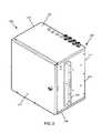
- FIG. 2is a perspective view of an exemplary fiber distribution hub having exemplary features of aspects in accordance with the principles of the present disclosure.
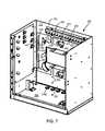
- FIG. 3is an exploded perspective view of a rack mount on the fiber distribution hub of FIG. 2 .
- FIG. 4is a perspective view of the fiber distribution hub of FIG. 2 having a front door in an open position.
- FIG. 5is a perspective view of the fiber distribution hub of FIG. 2 having the front door and a swing frame in an open position.
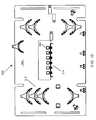
- FIG. 6is a schematic representation of an exemplary cable routing scheme for the fiber distribution hub of FIG. 2 .
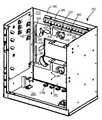
- FIG. 7is a perspective view of the fiber distribution hub of FIG. 2 with the front door, swing frame, and top panel removed.
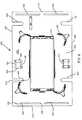
- FIG. 8is a front view of an exemplary adjustable plate suitable for use in the fiber distribution hub of FIG. 2 and having exemplary features of aspects in accordance with the principles of the present disclosure.
- FIG. 9is a rear view of the adjustable plate of FIG. 8 .
- FIG. 10is a front of an alternate embodiment of a plate suitable for use in the fiber distribution hub of FIG. 2 .
- FIG. 11is a rear view of the plate of FIG. 10 .
- FIG. 12is a perspective view of the fiber distribution hub of FIG. 7 with the adjustable plate in a first position.
- FIG. 13is a front view of the fiber distribution hub of FIG. 12 .
- FIG. 14is a perspective view of the fiber distribution hub of FIG. 7 with the adjustable plate in a second position.
- FIG. 15is a front view of the fiber distribution hub of FIG. 14 .
- a fiber distribution hubis typically designed to accommodate different entry points through which fiber optic cables can enter/exit the FDH.
- the fiber optic cableis secured to the FDH near the entry/exit location.
- the fiber optic cableis then routed to another location within the FDH such as a location having a splitter.
- damagei.e., attenuation losses, which are power losses caused by bending the optical fibers of the fiber optic cables beyond the minimum bend radius
- spaceis provide in the FDH adjacent to the entry points. This space provides room for an installer to secure the fiber optic cable to the FDH and room for the fiber optic cables to be routed from the entry point to other locations within the FDH without exceeding the minimum bend radius of the fiber optic cable.
- an FDHtypically includes cable entry points on opposite side panels.
- the FDHmay include a set of cable entry points on the top panel and a set of cable entry points on the bottom panel of the FDH. In some instances, however, only one of the sets of cable entry points is used in the field. If only one of the sets of cable entry points is used, the FDH includes space adjacent to the other set of cable entry points that is unnecessary. However, as the manufacturer and the installer are often unaware of which cable entry points will be used until the time of installation, both spaces are provided to assure proper installation and routing of the fiber optic cable within the FDH regardless of which set of cable entry points is used.
- the present disclosureprovides an FDH having an adjustable plate disposed on a panel from which a first panel and an oppositely disposed second panel extend outwardly.
- the first and second panelsinclude first and second sets of cable openings, respectively.
- the adjustable plateis adapted for selective movement between a first position and a second position relative to the panel of the FDH.
- the adjustable plateis slidably engaged with the panel such that the adjustable plate moves between an upper and a lower position. It will be understood, however, that the scope of the present disclosure is not limited to the adjustable plate being slidably engaged with the panel or to the adjustable plate being moveable between an upper and lower position.
- the selective movement of the adjustable plate to the first positionprovides a space adjacent to the first set of cable openings while selective movement of the adjustable plate to the second position provides a space adjacent to the second set of cable openings.
- This selective movement of the adjustable plateprovides for space adjacent to the cable openings to be used in the field. As the selective movement of the adjustable plate eliminates the space adjacent to unused cable openings, the FDH is more compact.
- the FDH 200includes a cabinet, generally designated 202 , that houses internal components.
- the cabinet 202includes a back panel 212 , a top panel 204 that extends outwardly from the back panel 212 , a bottom panel 206 that is oppositely disposed from the top panel 204 and that extends outwardly from the back panel 212 , a first side panel 208 that extends outwardly from the back panel 212 , a second side panel 210 that is oppositely disposed from the first side panel 208 and that extends outwardly from the back panel 212 , and at least one front door 214 .
- the front door 214is pivotally mounted to the cabinet 202 by hinges 216 (shown in FIG. 4 ) to facilitate access to the components mounted within the cabinet 202 .
- the cabinet 202 of the FDH 200is configured to protect the internal components against rain, wind, dust, rodents, and other contaminants.
- the cabinet 202remains relatively lightweight for easy installation, and breathable to prevent accumulation of moisture in the unit.
- an aluminum construction with a heavy powder coat finishalso provides corrosion resistance.
- the cabinet 202is manufactured from heavy gauge aluminum and is NEMA-4X rated. In another embodiment, alternate materials can be used.
- the FDH 200is provided with a rack mount 220 disposed on the first and second side panels 208 , 210 .
- the rack mount 220is a bracket having a cabinet mount portion 222 and a rack mount portion 224 .
- the cabinet mount portion 222includes a plurality of through holes 226 .
- the through holes 226are disposed on the cabinet mount portion 222 of the rack mount 220 such that the through holes 226 may be generally aligned with rack mount holes 228 disposed on the first and second side panels 208 , 210 of the cabinet 202 .
- the through holes 226 in the cabinet mount portion 222 and the rack mount holes 228are adapted to receive fasteners 230 (e.g., screws, bolts, rivets, etc.).
- the rack mount portion 224includes a plurality of mounting holes 231 .
- the mounting holes 231are adapted to receive fasteners (e.g., screws, bolts, rivets, etc.) for mounting the cabinet 202 to a rack. It will be understood, however, that while a rack mount 220 has been shown, the scope of the present disclosure is not limited to the cabinet 202 having a rack mount 220 as the cabinet 202 could include a pole mount structure or other structure.
- the top and bottom panels 204 , 206include a plurality of first and second cable openings 218 a , 218 b , respectively (cable openings 218 b are shown in FIG. 7 ).
- the first and second cable openings 218 a , 218 bare paths through which cable enters and exits the cabinet 202 .
- the FDH 200is shown with the front door 214 in an open position.
- the FDH 200includes a swing frame 232 disposed in an interior of the cabinet 202 .
- the swing frame 232is pivotally mounted to the cabinet 202 .
- the swing frame 232is mounted to the second side panel 210 by a hinge 234 .
- the swing frame 232pivots about the hinge 234 between a closed position, shown in FIG. 4 , and an open position, shown in FIG. 5 .
- the swing frame 232includes a bulkhead 236 that divides the swing frame 232 into a front portion 238 (shown in FIG. 4 ) and a rear portion 240 (shown in FIG. 5 ).
- the bulkhead 236includes a main panel 242 having a termination region 244 and a storage region 246 .
- at least one termination module 248is provided at the termination region 244 and at least one storage module 250 (shown schematically in FIG. 6 ) is provided at the storage region 246 .
- the bulkhead 236also includes a secondary panel 252 (shown in FIG. 4 ) positioned adjacent the main panel 242 and configured for cable management.
- One or more feeder cable interfaces 254(shown schematically in FIG.
- At least one splitter module housing 256(shown schematically in FIG. 6 ) accommodating one or more splitter modules 258 (shown in schematically FIG. 6 ) is positioned at the top of the swing frame 232 .
- a feeder cable 302is initially routed into the FDH 200 through the first and second cable openings 218 a , 218 b in the top or bottom panels 204 , 206 of the cabinet 202 .
- the fibers of the feeder cable 302can include ribbon fibers.
- An example feeder cable 302may include twelve to forty-eight individual fibers connected to a service provider central office 110 .
- the fibers of the feeder cable 302are routed to the feeder cable interface 254 (e.g., fiber optic adapter modules, a splice tray, etc.).
- one or more of the fibers of the feeder cable 302are individually connected to separate splitter input fibers 306 .
- the splitter input fibers 306are routed from the feeder cable interface 254 to the splitter module housing 256 .
- the splitter input fibers 306are connected to separate splitter modules 258 , wherein the splitter input fibers 306 are each split into multiple pigtails 312 , each having connectorized ends 314 .
- the fibers of the feeder cable 302can be connectorized and can be routed directly to the splitter modules 258 thereby bypassing or eliminating the need for an intermediate feeder cable interface 254 .
- the connectorized ends 314can be temporarily stored on a storage module 316 that is mounted at the storage region 246 of the swing frame 232 .
- the pigtails 312are routed from the splitter modules 258 to the termination module 248 that is provided at the termination region 244 of the swing frame 232 .
- the connectorized ends 314 of the pigtails 312are connected to connectorized ends 318 of fibers of a distribution cable 320 within an adapter 322 .
- the termination region 244is the dividing line between the incoming fibers and the outgoing fibers.
- a typical distribution cable 320forms the F 2 portion of the network 100 (shown in FIG. 1 ) and typically includes a plurality of fibers (e.g., 144, 216, or 432 fibers) that are routed from the FDH 200 to end user 115 locations.
- the cabinet 202is shown with the front door 214 , the swing frame 232 and the top panel 204 removed for ease of illustration.
- the back panel 212includes a first bracket mounting location 280 disposed near the top panel 204 of the cabinet 202 and a second bracket mounting location 282 disposed near the bottom panel 206 of the cabinet 202 .
- the first and second cable bracket mounting locations 280 , 282include a plurality of mounting holes 284 that are adapted to receive bracket mounts of a cable bracket 286 for securing cable that enters the interior of the cabinet 202 .
- the first and second bracket mounting locations 280 , 282are disposed adjacent to the first and second cable openings 218 a , 218 b , respectively, in the top and bottom panels 204 , 206 . If the first cable openings 218 a are being used for cable to enter and exit the cabinet 202 , the cable bracket 286 is mounted to the first bracket mounting location 280 while the mounting holes 284 in the second bracket mounting location 282 are plugged to protect the interior of the cabinet 202 from environmental elements (e.g., dust, wind, rain, ice, etc.).
- environmental elementse.g., dust, wind, rain, ice, etc.
- the cable bracket 286is mounted to the second bracket mounting location 282 while the mounting holes 284 in the first bracket mounting location 280 are plugged to protect the interior of the cabinet 202 from environmental elements.
- the back panel 212further includes a plurality of pins 290 that extend outwardly from the back panel 212 into the interior of the cabinet 202 .
- the pins 290are threaded and adapted to receive a retention member (e.g., nut, etc.). It will be understood, however, that the scope of the present disclosure is not limited to the pins 290 being threaded.
- an adjustable plategenerally designated 400 , which is disposed adjacent to the back panel 212 in the interior of the cabinet 202 , is accessible.
- the adjustable plate 400includes a front surface 402 and a rear surface 404 .
- the adjustable plate 400is generally rectangular in shape. It will be understood, however, that the scope of the present disclosure is not limited to the adjustable plate 400 being generally rectangular in shape.
- the adjustable plate 400includes an upper end 406 , an oppositely disposed lower end 408 , a first side end 410 , and an oppositely disposed second side end 412 .
- the front surface 402 of the adjustable plate 400includes a splice tray mounting area 414 .
- a splice tray 416is shown mounted in the splice tray mounting area 414 .
- the front surface 402 of the adjustable plate 400further includes a cable management area 418 .
- Disposed within the cable management area 418are a plurality of bend radius protectors 420 and a plurality of cable holders 422 (best shown in FIG. 7 ).
- Each of the bend radius protectors 420includes a radius that is sized to be larger than the minimum bend radius of an optical fiber.
- each of the cable holders 422includes a base 424 , a first hook protrusion 426 that extends outwardly from the base 424 , and an oppositely disposed second hook protrusion 428 that extends outwardly from the base 424 .
- the first and second hook protrusions 426 , 428define a channel 430 (shown in FIG. 7 ) through which the optical fibers pass.
- the cable holders 422loosely retain the optical fibers in the cable management area 418 .
- the plate 500includes a front side 502 and a rear side 504 .
- the front side of the plate 500includes termination area 514 and a cable management area 518 .
- the termination area 514includes a plurality of fiber optic adapters 520 having first sides and opposite second sides.
- the first sides of the plurality of fiber optic adapters 512are adapted to receive connectorized ends of fibers of the feeder cable 302 (shown schematically in FIG. 6 ).
- the second sides of the fiber optic adapters 512are adapted to receive connectorized ends of the splitter input fibers 306 (shown schematically in FIG. 6 ).
- the adjustable plate 400includes slots 432 disposed adjacent to each of the first and second side ends 410 , 412 . It will be understood, however, that the scope of the present disclosure is not limited to slots 432 being disposed adjacent to each of the first and second side ends 410 , 412 , as slots 432 or holes could be disposed at other locations on the adjustable plate 400 . In the subject embodiment, and by way of example only, there are two slots 432 disposed adjacent to the first side end 410 and two slots disposed adjacent to the second side end 412 . Each of the slots 432 extends through the adjustable plate 400 .
- Each of the slots 432includes a first end 434 and an oppositely disposed second end 436 .
- the first end 434 of each of the slots 432is an upper end 434 while the second end 436 is a lower end 436 . It will be understood, however, that the scope of the present disclosure is not limited to the first end 434 being an upper end or to the second end 436 being a lower end.
- each slot 432is at least about 3 inches in length, about 4 inches in length, about 5 inches in length, about 6 inches in length, about 7 inches in length, about 8 inches in length, about 9 inches in length, about 10 inches in length, or about 12 inches in length. In another embodiment, and by way of example only, each slot 432 is in a range of about 5 to about 8 inches in length or about 6 to about 7 inches in length.
- Each slot 432is adapted to receive one pin 290 that extends outwardly from the back panel 212 .
- the engagement between the slots 432 of the adjustable plate 400 and the pins 290 of the back panel 212is selective sliding engagement.
- the adjustable plate 400 of the cabinet 202has been and will be further described as being selectively moveable between an upper and lower position, it will be understood that the scope of the present disclosure is not limited to the adjustable plate 400 being selectively moveable between an upper and lower position as the adjustable plate 400 could also be moved between a front and back position or a left and right position.
- the adjustable plate 400slides relative to the back panel 212 of the cabinet 202 such that the adjustable plate 400 is selectively moveable between a first position and a second position.
- each pin 290is disposed centrally between the upper end 434 and the lower end 436 of the respective slot 432 .
- the adjustable plate 400is shown in the first position.
- the first positionis a lower position.
- each pin 290is disposed adjacent to the upper end 434 of the respective slot 432 .
- a first space 437is provided above the upper end 406 of the adjustable plate 400 in which the cable entering the first cable openings 218 a can be mechanically secured (e.g., via the cable bracket 286 disposed in the first bracket mounting location 280 ), in which the cable entering the first cable openings 218 a can be routed to another location within the cabinet 202 using a proper bend radius, and/or in which individual optical fibers in the fiber optic cable can be fanned out or separated from the other optical fibers of the fiber optic cable.
- the adjustable plate 400is shown in the second position.
- the second positionis an upper position.
- each pin 290is disposed adjacent to the lower end 436 of the respective slot 432 in the adjustable plate 400 .
- a second space 439is provided below the lower end 408 of the adjustable plate 400 in which cable entering the second cable openings 218 b can be mechanically secured, in which the cable entering the second cable openings 218 b can be routed to another location within the cabinet 202 using a proper bend radius, and/or in which individual optical fibers can be fanned out from the other optical fibers of the fiber optic cable.
- the adjustable plate 400is moved from either the central position or the first position to the second position.
- the retention memberswhich are in tight engagement with the pins 290 , are loosened so that the adjustable plate 400 can move to the second position.
- the adjustable plate 400With the adjustable plate 400 in the second position, the adjustable plate 400 is secured to the back panel 212 by tightening the retention members on the pins 290 .
- the fiber optic cable 302is inserted into the cabinet 202 through the cable openings 218 a in the top panel, which is adjacent to the back panel 212 .
- the direction of movement of the adjustable plate 400 as the adjustable plate 400 is moved to the second positionis away from the cable openings 218 a , adequate space is provided for the fiber optic cable 302 to enter the cabinet 202 .
- the direction of movement of the adjustable plateis in a direction that is generally parallel with an axis of one of the cable openings 218 a through which the fiber optic cable 302 is to be inserted. It will be understood, however, that the scope of the present disclosure is not limited to the direction of movement of the adjustable plate being generally parallel to an axis of one of the cable openings 218 a through which the fiber optic cable 302 is to be inserted.
- the fiber optic cable 302can be secured to the back panel 212 through the cable bracket 286 mounted in the first bracket mounting location 280 on the back panel 212 .
- the mounting holes 284 associated with the second bracket mounting location 282can be plugged.
- the adjustable plate 400includes a plurality of openings 440 for providing clearance between the adjustable plate 400 and the plugged mounting holes 284 .
- the openings 440are “U-shaped” openings 440 that extend through the adjustable plate 400 at the upper end 406 and the lower end 408 .
- the openings 440are sized to provide clearance between the adjustable plate 400 and the plugged mounting holes 284 of the first bracket mounting location 280 or the second bracket mounting location 282 when the adjustable plate 400 is in the first position or second position, respectively.
Landscapes
- Physics & Mathematics (AREA)
- General Physics & Mathematics (AREA)
- Optics & Photonics (AREA)
- Light Guides In General And Applications Therefor (AREA)
Abstract
Description
Claims (16)
Priority Applications (1)
| Application Number | Priority Date | Filing Date | Title |
|---|---|---|---|
| US12/397,479US7715682B2 (en) | 2008-03-04 | 2009-03-04 | Fiber distribution hub having an adjustable plate |
Applications Claiming Priority (2)
| Application Number | Priority Date | Filing Date | Title |
|---|---|---|---|
| US3355008P | 2008-03-04 | 2008-03-04 | |
| US12/397,479US7715682B2 (en) | 2008-03-04 | 2009-03-04 | Fiber distribution hub having an adjustable plate |
Publications (2)
| Publication Number | Publication Date |
|---|---|
| US20090226143A1 US20090226143A1 (en) | 2009-09-10 |
| US7715682B2true US7715682B2 (en) | 2010-05-11 |
Family
ID=41053689
Family Applications (1)
| Application Number | Title | Priority Date | Filing Date |
|---|---|---|---|
| US12/397,479ActiveUS7715682B2 (en) | 2008-03-04 | 2009-03-04 | Fiber distribution hub having an adjustable plate |
Country Status (1)
| Country | Link |
|---|---|
| US (1) | US7715682B2 (en) |
Cited By (2)
| Publication number | Priority date | Publication date | Assignee | Title |
|---|---|---|---|---|
| US20140090866A1 (en)* | 2012-10-03 | 2014-04-03 | Daniel Wylder Sherwood | Wiring combiner box |
| US10578823B2 (en) | 2017-12-28 | 2020-03-03 | Afl Ig Llc | Wall cabinets and fiber management trays |
Families Citing this family (12)
| Publication number | Priority date | Publication date | Assignee | Title |
|---|---|---|---|---|
| US7720344B2 (en)* | 2007-10-22 | 2010-05-18 | Adc Telecommunications, Inc. | Fiber distribution hub |
| US8606067B2 (en)* | 2009-09-04 | 2013-12-10 | Adc Telecommunications, Inc. | Pedestal terminal with swing frame |
| US11251608B2 (en) | 2010-07-13 | 2022-02-15 | Raycap S.A. | Overvoltage protection system for wireless communication systems |
| US8824851B2 (en)* | 2010-08-27 | 2014-09-02 | Commscope, Inc. Of North Carolina | Communications enclosure having rear mounted bracket and method of securing a cable bundle to a communications enclosure using a rear mounted bracket |
| US9279950B2 (en) | 2011-03-28 | 2016-03-08 | Afl Telecommunications Llc | Exterior distribution pedestal cabinet |
| US8913867B2 (en)* | 2011-11-21 | 2014-12-16 | Opterna Technology Limited | Fiber optic collector and terminal assemblies |
| US9971119B2 (en)* | 2015-11-03 | 2018-05-15 | Raycap Intellectual Property Ltd. | Modular fiber optic cable splitter |
| US10802237B2 (en) | 2015-11-03 | 2020-10-13 | Raycap S.A. | Fiber optic cable management system |
| WO2018136812A1 (en) | 2017-01-20 | 2018-07-26 | Raycap S.A. | Power transmission system for wireless communication systems |
| US10971928B2 (en) | 2018-08-28 | 2021-04-06 | Raycap Ip Assets Ltd | Integrated overvoltage protection and monitoring system |
| US11677164B2 (en) | 2019-09-25 | 2023-06-13 | Raycap Ip Assets Ltd | Hybrid antenna distribution unit |
| US12237134B2 (en) | 2021-12-28 | 2025-02-25 | Raycap Ip Assets Ltd | Circuit protection for hybrid antenna distribution units |
Citations (36)
| Publication number | Priority date | Publication date | Assignee | Title |
|---|---|---|---|---|
| US5717810A (en) | 1994-01-21 | 1998-02-10 | Adc Telecommunications, Inc. | High-density fiber distribution frame |
| US5734774A (en) | 1995-11-30 | 1998-03-31 | Lucent Technologies Inc. | Outdoor electronics cabinet |
| US6160946A (en) | 1998-07-27 | 2000-12-12 | Adc Telecommunications, Inc. | Outside plant fiber distribution apparatus and method |
| US6535682B1 (en) | 1999-03-01 | 2003-03-18 | Adc Telecommunications, Inc. | Optical fiber distribution frame with connector modules |
| US6556763B1 (en) | 1999-03-01 | 2003-04-29 | Adc Telecommunications, Inc. | Optical fiber distribution frame with connector modules |
| US6715719B2 (en) | 2002-03-27 | 2004-04-06 | Adc Telecommunications, Inc. | Coupler for cable trough |
| US6778752B2 (en) | 2002-05-31 | 2004-08-17 | Corning Cable Systems Llc | Below grade closure for local convergence point |
| US6788786B1 (en) | 2000-09-22 | 2004-09-07 | Adc Telecommunications, Inc. | Multimedia patching box |
| US6792190B2 (en) | 2001-06-01 | 2004-09-14 | Telect, Inc. | High density fiber optic splitter/connector tray system |
| US6792191B1 (en) | 2003-04-22 | 2004-09-14 | Corning Cable Systems Llc | Local convergence cabinet |
| US6909833B2 (en) | 2002-03-15 | 2005-06-21 | Fiber Optic Network Solutions, Inc. | Optical fiber enclosure system using integrated optical connector and coupler assembly |
| US6920213B2 (en) | 2000-09-15 | 2005-07-19 | Verizon Services Corp. | Methods and apparatus for facilitating the interaction between multiple telephone and computer users |
| US6920274B2 (en) | 2003-12-23 | 2005-07-19 | Adc Telecommunications, Inc. | High density optical fiber distribution frame with modules |
| US6980725B1 (en) | 2002-04-30 | 2005-12-27 | Calix Networks, Inc. | Space reuse during technology upgrade in a protection area of an outdoor enclosure |
| US6983095B2 (en) | 2003-11-17 | 2006-01-03 | Fiber Optic Network Solutions Corporation | Systems and methods for managing optical fibers and components within an enclosure in an optical communications network |
| US20060110118A1 (en)* | 2004-11-24 | 2006-05-25 | Escoto Alejandro R | Optical fiber distribution apparatus |
| US7086539B2 (en) | 2002-10-21 | 2006-08-08 | Adc Telecommunications, Inc. | High density panel with rotating tray |
| US20060228086A1 (en)* | 2005-03-31 | 2006-10-12 | Matthew Holmberg | Adapter block including connector storage |
| US7139461B2 (en) | 1999-03-01 | 2006-11-21 | Adc Telecommunications, Inc. | Optical fiber distribution frame with outside plant enclosure |
| US20070031100A1 (en) | 2005-08-04 | 2007-02-08 | Garcia Cesar G | Optical fiber distribution cabinet |
| US7198409B2 (en) | 2003-06-30 | 2007-04-03 | Adc Telecommunications, Inc. | Fiber optic connector holder and method |
| US7218827B2 (en) | 2004-06-18 | 2007-05-15 | Adc Telecommunications, Inc. | Multi-position fiber optic connector holder and method |
| US7228036B2 (en) | 2004-11-30 | 2007-06-05 | Corning Cable Systems Llc | Adjustable tether assembly for fiber optic distribution cable |
| US7233731B2 (en) | 2003-07-02 | 2007-06-19 | Adc Telecommunications, Inc. | Telecommunications connection cabinet |
| US7245809B1 (en) | 2005-12-28 | 2007-07-17 | Adc Telecommunications, Inc. | Splitter modules for fiber distribution hubs |
| US20070165995A1 (en) | 2005-08-30 | 2007-07-19 | Randy Reagan | Fiber distribution hub with modular termination blocks |
| US20070192817A1 (en)* | 2006-02-13 | 2007-08-16 | Landry Edward T | Fiber distribution hub with outside accessible grounding terminals |
| US7298952B2 (en) | 2003-03-20 | 2007-11-20 | Tyco Electronics Corporation | Optical fiber interconnect cabinets, termination modules and fiber connectivity management for the same |
| US20080008436A1 (en) | 2003-11-17 | 2008-01-10 | Fiber Optics Network Solutions Corp. | Hinged parking in fiber distribution hubs |
| US7340146B2 (en) | 2005-03-10 | 2008-03-04 | Yazaki Corporation | Dust shutter for an optical adapter |
| US7346254B2 (en) | 2005-08-29 | 2008-03-18 | Adc Telecommunications, Inc. | Fiber optic splitter module with connector access |
| US7376322B2 (en) | 2004-11-03 | 2008-05-20 | Adc Telecommunications, Inc. | Fiber optic module and system including rear connectors |
| US7400813B2 (en) | 2005-05-25 | 2008-07-15 | Adc Telecommunications, Inc. | Fiber optic splitter module |
| US7418181B2 (en) | 2006-02-13 | 2008-08-26 | Adc Telecommunications, Inc. | Fiber optic splitter module |
| US7416349B2 (en) | 2005-07-27 | 2008-08-26 | Adc Telecommunications, Inc. | Fiber optic adapter module |
| US7419384B2 (en) | 2002-03-16 | 2008-09-02 | Adc Gmbh | Plug for connection strips and method for the production thereof |
- 2009
- 2009-03-04USUS12/397,479patent/US7715682B2/enactiveActive
Patent Citations (62)
| Publication number | Priority date | Publication date | Assignee | Title |
|---|---|---|---|---|
| US5717810A (en) | 1994-01-21 | 1998-02-10 | Adc Telecommunications, Inc. | High-density fiber distribution frame |
| US5734774A (en) | 1995-11-30 | 1998-03-31 | Lucent Technologies Inc. | Outdoor electronics cabinet |
| US6160946A (en) | 1998-07-27 | 2000-12-12 | Adc Telecommunications, Inc. | Outside plant fiber distribution apparatus and method |
| US6535682B1 (en) | 1999-03-01 | 2003-03-18 | Adc Telecommunications, Inc. | Optical fiber distribution frame with connector modules |
| US6556763B1 (en) | 1999-03-01 | 2003-04-29 | Adc Telecommunications, Inc. | Optical fiber distribution frame with connector modules |
| US7139461B2 (en) | 1999-03-01 | 2006-11-21 | Adc Telecommunications, Inc. | Optical fiber distribution frame with outside plant enclosure |
| US7333707B2 (en) | 1999-03-01 | 2008-02-19 | Adc Telecommunications, Inc. | Optical fiber distribution frame with outside plant enclosure |
| US20090022467A1 (en) | 1999-03-01 | 2009-01-22 | Adc Telecommunications, Inc. | Optical fiber distribution frame with outside plant enclosure |
| US7149398B2 (en) | 1999-03-01 | 2006-12-12 | Adc Telecommunications, Inc. | Optical fiber distribution frame with outside plant enclosure |
| US6920213B2 (en) | 2000-09-15 | 2005-07-19 | Verizon Services Corp. | Methods and apparatus for facilitating the interaction between multiple telephone and computer users |
| US6788786B1 (en) | 2000-09-22 | 2004-09-07 | Adc Telecommunications, Inc. | Multimedia patching box |
| US6792190B2 (en) | 2001-06-01 | 2004-09-14 | Telect, Inc. | High density fiber optic splitter/connector tray system |
| US6909833B2 (en) | 2002-03-15 | 2005-06-21 | Fiber Optic Network Solutions, Inc. | Optical fiber enclosure system using integrated optical connector and coupler assembly |
| US7419384B2 (en) | 2002-03-16 | 2008-09-02 | Adc Gmbh | Plug for connection strips and method for the production thereof |
| US6715719B2 (en) | 2002-03-27 | 2004-04-06 | Adc Telecommunications, Inc. | Coupler for cable trough |
| US6980725B1 (en) | 2002-04-30 | 2005-12-27 | Calix Networks, Inc. | Space reuse during technology upgrade in a protection area of an outdoor enclosure |
| US6778752B2 (en) | 2002-05-31 | 2004-08-17 | Corning Cable Systems Llc | Below grade closure for local convergence point |
| US7086539B2 (en) | 2002-10-21 | 2006-08-08 | Adc Telecommunications, Inc. | High density panel with rotating tray |
| US7298952B2 (en) | 2003-03-20 | 2007-11-20 | Tyco Electronics Corporation | Optical fiber interconnect cabinets, termination modules and fiber connectivity management for the same |
| US6792191B1 (en) | 2003-04-22 | 2004-09-14 | Corning Cable Systems Llc | Local convergence cabinet |
| US20080019644A1 (en) | 2003-06-30 | 2008-01-24 | Adc Telecommunications, Inc. | Fiber optic connector holder and method |
| US7407330B2 (en) | 2003-06-30 | 2008-08-05 | Adc Telecommunications, Inc. | Fiber optic connector holder and method |
| US20090087157A1 (en) | 2003-06-30 | 2009-04-02 | Adc Telecommunications, Inc. | Fiber optic connector holder and method |
| US7198409B2 (en) | 2003-06-30 | 2007-04-03 | Adc Telecommunications, Inc. | Fiber optic connector holder and method |
| US20090074372A1 (en) | 2003-07-02 | 2009-03-19 | Adc Telecommunications, Inc. | Telecommunications connection cabinet |
| US7457503B2 (en) | 2003-07-02 | 2008-11-25 | Adc Telecommunications, Inc. | Telecommunications connection cabinet |
| US7233731B2 (en) | 2003-07-02 | 2007-06-19 | Adc Telecommunications, Inc. | Telecommunications connection cabinet |
| US7103255B2 (en) | 2003-11-17 | 2006-09-05 | Fiber Optic Networks Solutions Corporation | Optical splitter module |
| US7471869B2 (en) | 2003-11-17 | 2008-12-30 | Fiber Optics Network Solutions Corp. | Equipment layout for fiber distribution hubs |
| US7200317B2 (en) | 2003-11-17 | 2007-04-03 | Fiber Optic Network Solutions Corporation | Systems and methods for optical fiber distribution and management |
| US7369741B2 (en) | 2003-11-17 | 2008-05-06 | Fiber Optics Network Solutions Corp. | Storage adapter with dust cap posts |
| US7171102B2 (en) | 2003-11-17 | 2007-01-30 | Fiber Optic Network Solutions Corporation | Optical communication signal distribution enclosure |
| US7146089B2 (en) | 2003-11-17 | 2006-12-05 | Fiber Optic Network Solutions Corporation | Systems and methods for fiber distribution hub administration |
| US7400816B2 (en) | 2003-11-17 | 2008-07-15 | Fiber Optics Network Solutions Corp. | Telecommunications apparatus for distributing optical communications signals |
| US7088899B2 (en) | 2003-11-17 | 2006-08-08 | Fiber Optic Networks Solutions Corporation | Configuring pigtails in a fiber distribution hub |
| US6983095B2 (en) | 2003-11-17 | 2006-01-03 | Fiber Optic Network Solutions Corporation | Systems and methods for managing optical fibers and components within an enclosure in an optical communications network |
| US20080008436A1 (en) | 2003-11-17 | 2008-01-10 | Fiber Optics Network Solutions Corp. | Hinged parking in fiber distribution hubs |
| US6920274B2 (en) | 2003-12-23 | 2005-07-19 | Adc Telecommunications, Inc. | High density optical fiber distribution frame with modules |
| US20080019655A1 (en) | 2004-06-18 | 2008-01-24 | Adc Telecommunications, Inc. | Fiber Optic Splitter |
| US20080025684A1 (en) | 2004-06-18 | 2008-01-31 | Adc Telecommunications, Inc. | Fiber Optic Splitter |
| US7277620B2 (en) | 2004-06-18 | 2007-10-02 | Adc Telecommunications, Inc. | Fiber optic splitter |
| US7515805B2 (en) | 2004-06-18 | 2009-04-07 | Adc Telecommunications, Inc. | Fiber optic splitter |
| US7218827B2 (en) | 2004-06-18 | 2007-05-15 | Adc Telecommunications, Inc. | Multi-position fiber optic connector holder and method |
| US7519259B2 (en) | 2004-06-18 | 2009-04-14 | Adc Telecommunications, Inc. | Increasing capacity of a telecommunications cabinet |
| US20080317425A1 (en) | 2004-06-18 | 2008-12-25 | Adc Telecommunications, Inc. | Telecommunications cabinet with connector storage |
| US20090190896A1 (en) | 2004-06-18 | 2009-07-30 | Adc Telecommunications, Inc. | Telecommunications cabinet with connector storage |
| US20090196565A1 (en) | 2004-06-18 | 2009-08-06 | Adc Telecommunications, Inc. | Telecommunications Connection Cabinet |
| US7376322B2 (en) | 2004-11-03 | 2008-05-20 | Adc Telecommunications, Inc. | Fiber optic module and system including rear connectors |
| US20060110118A1 (en)* | 2004-11-24 | 2006-05-25 | Escoto Alejandro R | Optical fiber distribution apparatus |
| US7228036B2 (en) | 2004-11-30 | 2007-06-05 | Corning Cable Systems Llc | Adjustable tether assembly for fiber optic distribution cable |
| US7340146B2 (en) | 2005-03-10 | 2008-03-04 | Yazaki Corporation | Dust shutter for an optical adapter |
| US7194181B2 (en) | 2005-03-31 | 2007-03-20 | Adc Telecommunications, Inc. | Adapter block including connector storage |
| US20060228086A1 (en)* | 2005-03-31 | 2006-10-12 | Matthew Holmberg | Adapter block including connector storage |
| US7400813B2 (en) | 2005-05-25 | 2008-07-15 | Adc Telecommunications, Inc. | Fiber optic splitter module |
| US7416349B2 (en) | 2005-07-27 | 2008-08-26 | Adc Telecommunications, Inc. | Fiber optic adapter module |
| US20070031100A1 (en) | 2005-08-04 | 2007-02-08 | Garcia Cesar G | Optical fiber distribution cabinet |
| US7346254B2 (en) | 2005-08-29 | 2008-03-18 | Adc Telecommunications, Inc. | Fiber optic splitter module with connector access |
| US20070165995A1 (en) | 2005-08-30 | 2007-07-19 | Randy Reagan | Fiber distribution hub with modular termination blocks |
| US20080124039A1 (en) | 2005-12-28 | 2008-05-29 | Adc Telecommunications, Inc. | Splitter Modules for Fiber Distribution Hubs |
| US7245809B1 (en) | 2005-12-28 | 2007-07-17 | Adc Telecommunications, Inc. | Splitter modules for fiber distribution hubs |
| US7418181B2 (en) | 2006-02-13 | 2008-08-26 | Adc Telecommunications, Inc. | Fiber optic splitter module |
| US20070192817A1 (en)* | 2006-02-13 | 2007-08-16 | Landry Edward T | Fiber distribution hub with outside accessible grounding terminals |
Cited By (3)
| Publication number | Priority date | Publication date | Assignee | Title |
|---|---|---|---|---|
| US20140090866A1 (en)* | 2012-10-03 | 2014-04-03 | Daniel Wylder Sherwood | Wiring combiner box |
| US9615470B2 (en)* | 2012-10-03 | 2017-04-04 | Sunlink Corporation | Wiring combiner box |
| US10578823B2 (en) | 2017-12-28 | 2020-03-03 | Afl Ig Llc | Wall cabinets and fiber management trays |
Also Published As
| Publication number | Publication date |
|---|---|
| US20090226143A1 (en) | 2009-09-10 |
Similar Documents
| Publication | Publication Date | Title |
|---|---|---|
| US7715682B2 (en) | Fiber distribution hub having an adjustable plate | |
| US12306450B2 (en) | Fiber distribution hub | |
| US8068712B2 (en) | Fiber distribution hub | |
| US7728225B2 (en) | Fiber distribution hub with dual swing frames | |
| US20200012060A1 (en) | Fiber distribution hub with swing frame and wrap-around doors | |
| US8121458B2 (en) | Fiber distribution hub with swing frame and modular termination panels | |
| US7526172B2 (en) | Splitter modules for fiber distribution hubs | |
| US20250306323A1 (en) | Fiber distribution hub including sealed splice module |
Legal Events
| Date | Code | Title | Description |
|---|---|---|---|
| AS | Assignment | Owner name:ADC TELECOMMUNICATIONS, INC., MINNESOTA Free format text:ASSIGNMENT OF ASSIGNORS INTEREST;ASSIGNOR:BECK, RONALD A.;REEL/FRAME:022698/0718 Effective date:20090513 Owner name:ADC TELECOMMUNICATIONS, INC.,MINNESOTA Free format text:ASSIGNMENT OF ASSIGNORS INTEREST;ASSIGNOR:BECK, RONALD A.;REEL/FRAME:022698/0718 Effective date:20090513 | |
| STCF | Information on status: patent grant | Free format text:PATENTED CASE | |
| FPAY | Fee payment | Year of fee payment:4 | |
| AS | Assignment | Owner name:TYCO ELECTRONICS SERVICES GMBH, SWITZERLAND Free format text:ASSIGNMENT OF ASSIGNORS INTEREST;ASSIGNOR:ADC TELECOMMUNICATIONS, INC.;REEL/FRAME:036060/0174 Effective date:20110930 | |
| AS | Assignment | Owner name:COMMSCOPE EMEA LIMITED, IRELAND Free format text:ASSIGNMENT OF ASSIGNORS INTEREST;ASSIGNOR:TYCO ELECTRONICS SERVICES GMBH;REEL/FRAME:036956/0001 Effective date:20150828 | |
| AS | Assignment | Owner name:COMMSCOPE TECHNOLOGIES LLC, NORTH CAROLINA Free format text:ASSIGNMENT OF ASSIGNORS INTEREST;ASSIGNOR:COMMSCOPE EMEA LIMITED;REEL/FRAME:037012/0001 Effective date:20150828 | |
| AS | Assignment | Owner name:JPMORGAN CHASE BANK, N.A., AS COLLATERAL AGENT, ILLINOIS Free format text:PATENT SECURITY AGREEMENT (TERM);ASSIGNOR:COMMSCOPE TECHNOLOGIES LLC;REEL/FRAME:037513/0709 Effective date:20151220 Owner name:JPMORGAN CHASE BANK, N.A., AS COLLATERAL AGENT, ILLINOIS Free format text:PATENT SECURITY AGREEMENT (ABL);ASSIGNOR:COMMSCOPE TECHNOLOGIES LLC;REEL/FRAME:037514/0196 Effective date:20151220 Owner name:JPMORGAN CHASE BANK, N.A., AS COLLATERAL AGENT, IL Free format text:PATENT SECURITY AGREEMENT (TERM);ASSIGNOR:COMMSCOPE TECHNOLOGIES LLC;REEL/FRAME:037513/0709 Effective date:20151220 Owner name:JPMORGAN CHASE BANK, N.A., AS COLLATERAL AGENT, IL Free format text:PATENT SECURITY AGREEMENT (ABL);ASSIGNOR:COMMSCOPE TECHNOLOGIES LLC;REEL/FRAME:037514/0196 Effective date:20151220 | |
| CC | Certificate of correction | ||
| MAFP | Maintenance fee payment | Free format text:PAYMENT OF MAINTENANCE FEE, 8TH YEAR, LARGE ENTITY (ORIGINAL EVENT CODE: M1552) Year of fee payment:8 | |
| AS | Assignment | Owner name:ALLEN TELECOM LLC, ILLINOIS Free format text:RELEASE BY SECURED PARTY;ASSIGNOR:JPMORGAN CHASE BANK, N.A.;REEL/FRAME:048840/0001 Effective date:20190404 Owner name:ANDREW LLC, NORTH CAROLINA Free format text:RELEASE BY SECURED PARTY;ASSIGNOR:JPMORGAN CHASE BANK, N.A.;REEL/FRAME:048840/0001 Effective date:20190404 Owner name:COMMSCOPE, INC. OF NORTH CAROLINA, NORTH CAROLINA Free format text:RELEASE BY SECURED PARTY;ASSIGNOR:JPMORGAN CHASE BANK, N.A.;REEL/FRAME:048840/0001 Effective date:20190404 Owner name:COMMSCOPE TECHNOLOGIES LLC, NORTH CAROLINA Free format text:RELEASE BY SECURED PARTY;ASSIGNOR:JPMORGAN CHASE BANK, N.A.;REEL/FRAME:048840/0001 Effective date:20190404 Owner name:REDWOOD SYSTEMS, INC., NORTH CAROLINA Free format text:RELEASE BY SECURED PARTY;ASSIGNOR:JPMORGAN CHASE BANK, N.A.;REEL/FRAME:048840/0001 Effective date:20190404 Owner name:COMMSCOPE, INC. OF NORTH CAROLINA, NORTH CAROLINA Free format text:RELEASE BY SECURED PARTY;ASSIGNOR:JPMORGAN CHASE BANK, N.A.;REEL/FRAME:049260/0001 Effective date:20190404 Owner name:COMMSCOPE TECHNOLOGIES LLC, NORTH CAROLINA Free format text:RELEASE BY SECURED PARTY;ASSIGNOR:JPMORGAN CHASE BANK, N.A.;REEL/FRAME:049260/0001 Effective date:20190404 Owner name:REDWOOD SYSTEMS, INC., NORTH CAROLINA Free format text:RELEASE BY SECURED PARTY;ASSIGNOR:JPMORGAN CHASE BANK, N.A.;REEL/FRAME:049260/0001 Effective date:20190404 Owner name:ANDREW LLC, NORTH CAROLINA Free format text:RELEASE BY SECURED PARTY;ASSIGNOR:JPMORGAN CHASE BANK, N.A.;REEL/FRAME:049260/0001 Effective date:20190404 Owner name:ALLEN TELECOM LLC, ILLINOIS Free format text:RELEASE BY SECURED PARTY;ASSIGNOR:JPMORGAN CHASE BANK, N.A.;REEL/FRAME:049260/0001 Effective date:20190404 | |
| AS | Assignment | Owner name:JPMORGAN CHASE BANK, N.A., NEW YORK Free format text:TERM LOAN SECURITY AGREEMENT;ASSIGNORS:COMMSCOPE, INC. OF NORTH CAROLINA;COMMSCOPE TECHNOLOGIES LLC;ARRIS ENTERPRISES LLC;AND OTHERS;REEL/FRAME:049905/0504 Effective date:20190404 Owner name:WILMINGTON TRUST, NATIONAL ASSOCIATION, AS COLLATE Free format text:PATENT SECURITY AGREEMENT;ASSIGNOR:COMMSCOPE TECHNOLOGIES LLC;REEL/FRAME:049892/0051 Effective date:20190404 Owner name:JPMORGAN CHASE BANK, N.A., NEW YORK Free format text:ABL SECURITY AGREEMENT;ASSIGNORS:COMMSCOPE, INC. OF NORTH CAROLINA;COMMSCOPE TECHNOLOGIES LLC;ARRIS ENTERPRISES LLC;AND OTHERS;REEL/FRAME:049892/0396 Effective date:20190404 Owner name:WILMINGTON TRUST, NATIONAL ASSOCIATION, AS COLLATERAL AGENT, CONNECTICUT Free format text:PATENT SECURITY AGREEMENT;ASSIGNOR:COMMSCOPE TECHNOLOGIES LLC;REEL/FRAME:049892/0051 Effective date:20190404 | |
| MAFP | Maintenance fee payment | Free format text:PAYMENT OF MAINTENANCE FEE, 12TH YEAR, LARGE ENTITY (ORIGINAL EVENT CODE: M1553); ENTITY STATUS OF PATENT OWNER: LARGE ENTITY Year of fee payment:12 | |
| AS | Assignment | Owner name:WILMINGTON TRUST, DELAWARE Free format text:SECURITY INTEREST;ASSIGNORS:ARRIS SOLUTIONS, INC.;ARRIS ENTERPRISES LLC;COMMSCOPE TECHNOLOGIES LLC;AND OTHERS;REEL/FRAME:060752/0001 Effective date:20211115 | |
| AS | Assignment | Owner name:APOLLO ADMINISTRATIVE AGENCY LLC, NEW YORK Free format text:SECURITY INTEREST;ASSIGNORS:ARRIS ENTERPRISES LLC;COMMSCOPE TECHNOLOGIES LLC;COMMSCOPE INC., OF NORTH CAROLINA;AND OTHERS;REEL/FRAME:069889/0114 Effective date:20241217 | |
| AS | Assignment | Owner name:RUCKUS WIRELESS, LLC (F/K/A RUCKUS WIRELESS, INC.), NORTH CAROLINA Free format text:RELEASE OF SECURITY INTEREST AT REEL/FRAME 049905/0504;ASSIGNOR:JPMORGAN CHASE BANK, N.A., AS COLLATERAL AGENT;REEL/FRAME:071477/0255 Effective date:20241217 Owner name:COMMSCOPE TECHNOLOGIES LLC, NORTH CAROLINA Free format text:RELEASE OF SECURITY INTEREST AT REEL/FRAME 049905/0504;ASSIGNOR:JPMORGAN CHASE BANK, N.A., AS COLLATERAL AGENT;REEL/FRAME:071477/0255 Effective date:20241217 Owner name:COMMSCOPE, INC. OF NORTH CAROLINA, NORTH CAROLINA Free format text:RELEASE OF SECURITY INTEREST AT REEL/FRAME 049905/0504;ASSIGNOR:JPMORGAN CHASE BANK, N.A., AS COLLATERAL AGENT;REEL/FRAME:071477/0255 Effective date:20241217 Owner name:ARRIS SOLUTIONS, INC., NORTH CAROLINA Free format text:RELEASE OF SECURITY INTEREST AT REEL/FRAME 049905/0504;ASSIGNOR:JPMORGAN CHASE BANK, N.A., AS COLLATERAL AGENT;REEL/FRAME:071477/0255 Effective date:20241217 Owner name:ARRIS TECHNOLOGY, INC., NORTH CAROLINA Free format text:RELEASE OF SECURITY INTEREST AT REEL/FRAME 049905/0504;ASSIGNOR:JPMORGAN CHASE BANK, N.A., AS COLLATERAL AGENT;REEL/FRAME:071477/0255 Effective date:20241217 Owner name:ARRIS ENTERPRISES LLC (F/K/A ARRIS ENTERPRISES, INC.), NORTH CAROLINA Free format text:RELEASE OF SECURITY INTEREST AT REEL/FRAME 049905/0504;ASSIGNOR:JPMORGAN CHASE BANK, N.A., AS COLLATERAL AGENT;REEL/FRAME:071477/0255 Effective date:20241217 |