US7714936B1 - Omniview motionless camera orientation system - Google Patents
Omniview motionless camera orientation systemDownload PDFInfo
- Publication number
- US7714936B1 US7714936B1US08/887,319US88731997AUS7714936B1US 7714936 B1US7714936 B1US 7714936B1US 88731997 AUS88731997 AUS 88731997AUS 7714936 B1US7714936 B1US 7714936B1
- Authority
- US
- United States
- Prior art keywords
- image
- cos
- sin
- camera
- view
- Prior art date
- Legal status (The legal status is an assumption and is not a legal conclusion. Google has not performed a legal analysis and makes no representation as to the accuracy of the status listed.)
- Expired - Fee Related
Links
Images


Classifications
- G—PHYSICS
- G06—COMPUTING OR CALCULATING; COUNTING
- G06T—IMAGE DATA PROCESSING OR GENERATION, IN GENERAL
- G06T3/00—Geometric image transformations in the plane of the image
- G06T3/04—Context-preserving transformations, e.g. by using an importance map
- G06T3/047—Fisheye or wide-angle transformations
- G—PHYSICS
- G06—COMPUTING OR CALCULATING; COUNTING
- G06F—ELECTRIC DIGITAL DATA PROCESSING
- G06F16/00—Information retrieval; Database structures therefor; File system structures therefor
- G06F16/40—Information retrieval; Database structures therefor; File system structures therefor of multimedia data, e.g. slideshows comprising image and additional audio data
- G—PHYSICS
- G08—SIGNALLING
- G08B—SIGNALLING OR CALLING SYSTEMS; ORDER TELEGRAPHS; ALARM SYSTEMS
- G08B13/00—Burglar, theft or intruder alarms
- G08B13/18—Actuation by interference with heat, light, or radiation of shorter wavelength; Actuation by intruding sources of heat, light, or radiation of shorter wavelength
- G08B13/189—Actuation by interference with heat, light, or radiation of shorter wavelength; Actuation by intruding sources of heat, light, or radiation of shorter wavelength using passive radiation detection systems
- G08B13/194—Actuation by interference with heat, light, or radiation of shorter wavelength; Actuation by intruding sources of heat, light, or radiation of shorter wavelength using passive radiation detection systems using image scanning and comparing systems
- G08B13/196—Actuation by interference with heat, light, or radiation of shorter wavelength; Actuation by intruding sources of heat, light, or radiation of shorter wavelength using passive radiation detection systems using image scanning and comparing systems using television cameras
- G08B13/19617—Surveillance camera constructional details
- G08B13/19626—Surveillance camera constructional details optical details, e.g. lenses, mirrors or multiple lenses
- G08B13/19628—Surveillance camera constructional details optical details, e.g. lenses, mirrors or multiple lenses of wide angled cameras and camera groups, e.g. omni-directional cameras, fish eye, single units having multiple cameras achieving a wide angle view
- G—PHYSICS
- G08—SIGNALLING
- G08B—SIGNALLING OR CALLING SYSTEMS; ORDER TELEGRAPHS; ALARM SYSTEMS
- G08B13/00—Burglar, theft or intruder alarms
- G08B13/18—Actuation by interference with heat, light, or radiation of shorter wavelength; Actuation by intruding sources of heat, light, or radiation of shorter wavelength
- G08B13/189—Actuation by interference with heat, light, or radiation of shorter wavelength; Actuation by intruding sources of heat, light, or radiation of shorter wavelength using passive radiation detection systems
- G08B13/194—Actuation by interference with heat, light, or radiation of shorter wavelength; Actuation by intruding sources of heat, light, or radiation of shorter wavelength using passive radiation detection systems using image scanning and comparing systems
- G08B13/196—Actuation by interference with heat, light, or radiation of shorter wavelength; Actuation by intruding sources of heat, light, or radiation of shorter wavelength using passive radiation detection systems using image scanning and comparing systems using television cameras
- G08B13/19678—User interface
- G08B13/19689—Remote control of cameras, e.g. remote orientation or image zooming control for a PTZ camera
- H—ELECTRICITY
- H04—ELECTRIC COMMUNICATION TECHNIQUE
- H04N—PICTORIAL COMMUNICATION, e.g. TELEVISION
- H04N1/00—Scanning, transmission or reproduction of documents or the like, e.g. facsimile transmission; Details thereof
- H04N1/21—Intermediate information storage
- H04N1/2104—Intermediate information storage for one or a few pictures
- H04N1/2158—Intermediate information storage for one or a few pictures using a detachable storage unit
- H—ELECTRICITY
- H04—ELECTRIC COMMUNICATION TECHNIQUE
- H04N—PICTORIAL COMMUNICATION, e.g. TELEVISION
- H04N1/00—Scanning, transmission or reproduction of documents or the like, e.g. facsimile transmission; Details thereof
- H04N1/21—Intermediate information storage
- H04N1/2166—Intermediate information storage for mass storage, e.g. in document filing systems
- H04N1/217—Interfaces allowing access to a single user
- H—ELECTRICITY
- H04—ELECTRIC COMMUNICATION TECHNIQUE
- H04N—PICTORIAL COMMUNICATION, e.g. TELEVISION
- H04N23/00—Cameras or camera modules comprising electronic image sensors; Control thereof
- H04N23/58—Means for changing the camera field of view without moving the camera body, e.g. nutating or panning of optics or image sensors
- H—ELECTRICITY
- H04—ELECTRIC COMMUNICATION TECHNIQUE
- H04N—PICTORIAL COMMUNICATION, e.g. TELEVISION
- H04N23/00—Cameras or camera modules comprising electronic image sensors; Control thereof
- H04N23/60—Control of cameras or camera modules
- H04N23/698—Control of cameras or camera modules for achieving an enlarged field of view, e.g. panoramic image capture
- H—ELECTRICITY
- H04—ELECTRIC COMMUNICATION TECHNIQUE
- H04N—PICTORIAL COMMUNICATION, e.g. TELEVISION
- H04N25/00—Circuitry of solid-state image sensors [SSIS]; Control thereof
- H—ELECTRICITY
- H04—ELECTRIC COMMUNICATION TECHNIQUE
- H04N—PICTORIAL COMMUNICATION, e.g. TELEVISION
- H04N5/00—Details of television systems
- H04N5/222—Studio circuitry; Studio devices; Studio equipment
- H04N5/262—Studio circuits, e.g. for mixing, switching-over, change of character of image, other special effects ; Cameras specially adapted for the electronic generation of special effects
- H04N5/2628—Alteration of picture size, shape, position or orientation, e.g. zooming, rotation, rolling, perspective, translation
- H—ELECTRICITY
- H04—ELECTRIC COMMUNICATION TECHNIQUE
- H04N—PICTORIAL COMMUNICATION, e.g. TELEVISION
- H04N7/00—Television systems
- H04N7/002—Special television systems not provided for by H04N7/007 - H04N7/18
- H—ELECTRICITY
- H04—ELECTRIC COMMUNICATION TECHNIQUE
- H04N—PICTORIAL COMMUNICATION, e.g. TELEVISION
- H04N7/00—Television systems
- H04N7/18—Closed-circuit television [CCTV] systems, i.e. systems in which the video signal is not broadcast
- H04N7/183—Closed-circuit television [CCTV] systems, i.e. systems in which the video signal is not broadcast for receiving images from a single remote source
- A—HUMAN NECESSITIES
- A61—MEDICAL OR VETERINARY SCIENCE; HYGIENE
- A61B—DIAGNOSIS; SURGERY; IDENTIFICATION
- A61B90/00—Instruments, implements or accessories specially adapted for surgery or diagnosis and not covered by any of the groups A61B1/00 - A61B50/00, e.g. for luxation treatment or for protecting wound edges
- A61B90/08—Accessories or related features not otherwise provided for
- A61B2090/0813—Accessories designed for easy sterilising, i.e. re-usable
Definitions
- This inventionrelates generally to an apparatus and method for transforming perspective-distorted circular field of view images into non-distorted, normal perspective images having various orientations, rotations, and magnifications within the field of view.
- Camera viewing systemsare used in abundance for surveillance, inspection, security, and remote sensing. Remote viewing is critical, for example, for robotic manipulation tasks. Close viewing is necessary for detailed manipulation tasks wile wide-angle viewing aids positioning of the robotic system to avoid collisions with the work space.
- Most of these systemsuse either a fixed-mount camera with a limited viewing field to reduce distortion, or they utilize mechanical pan-and-tilt platforms and mechanized zoom lenses to orient the camera and magnify its image. In the applications where orientation of the camera and magnification of its image are required, the mechanical solution is large in size and can subtend a significant volume making the viewing system difficult to conceal or use in close quarters.
- Several camerasare usually necessary to provide wide-angle viewing of the work space.
- Camera viewing systemsthat use internal optics to provide wide viewing angles have also been developed in order to minimize the size and volume of the camera and the intrusion into the viewing area. These systems rely on the movement of either a mirror or prism to change the tilt-angle of orientation and provide mechanical rotation of the entire camera to change the pan angle of orientation. Additional lenses are used to minimize distortion. Using this means, the size of the camera orientation system can be minimized, but “blind spots” in the center of the view result. Also, these systems typically have no means of magnifying the image and or producing multiple images from a single camera.
- a further object of the present inventionis to provide the ability to produce multiple images with different orientations and magnifications simultaneously from a single input image.
- Another object of the present inventionis to be able to provide these images at real-time video rates, e.g. thirty transformed images per second, and to support various display format standards such as the National Television Standards Committee RS-170 signal format and/or higher resolution formats currently under development.
- an omnidirectional viewing systemthat produces the equivalent of pan, tilt, zoom, and rotation within a selected field-of-view with no moving parts. Further, the present invention includes means for controlling this omnidirectional viewing in surveillance applications.
- This deviceincludes a means for digitizing an incoming or prerecorded video image signal, transforming a portion of the video image based upon operator or preselected commands, and producing one or more output images that are in correct perspective for human viewing.
- the incoming imageis produced by a fisheye lens which has a wide angle field-of-view. This image is captured into an electronic memory buffer.
- a portion of the captured image, either in real time or as prerecorded, containing a region-of-interestis transformed into a perspective correct image by an image processing computer.
- the image processing computerprovides direct mapping of the image region-of-interest into a corrected image using an orthogonal set of transformation algorithms.
- the viewing orientationis designated by a command signal generated by either a human operator or computerized input.
- the transformed imageis deposited in a second electronic memory buffer where it is then manipulated to produce the output image or images as requested by the command signal. This is coupled with appropriate alarms and other outputs to provide a complete surveillance system for selected environments.
- FIG. 1shows a schematic block diagram of the signal processing portion of the present invention illustrating the major components thereof.
- FIG. 2is an exemplary drawing of a typical fisheye image used as input by the present invention.
- Lenses having other field-of-view valueswill produce images with similar distortion, particularly when the field-of-view is about eighty degrees or greater.
- FIG. 3is an exemplary drawing of the output image after correction for a desired image orientation and magnification within the original image.
- FIG. 4is a schematic diagram of the fundamental geometry that the present invention embodies to accomplish the image transformation.
- FIG. 5is a schematic diagram demonstrating the projection of the object plane and position vector into image plane coordinates.
- FIG. 6is a block diagram of the present invention as utilized for surveillance/inspection applications incorporating the basic transformation of video images obtained with, for example, wide angle lenses to correct for optical distortions due to the lenses, together with the control of the surveillance/inspection and appropriate alarm systems.
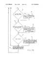
- FIGS. 7A and 7Btogether, show a logic flow diagram illustrating one specific embodiment of controller operation for manual and automatic surveillance operations of the present invention.
- the camera orientation systemIn order to minimize the size of the camera orientation system while maintaining the ability to zoom, a camera orientation system that utilizes electronic image transformations rather than mechanisms was developed. While numerous patents on mechanical pan-and-tilt systems have been filed, no approach using strictly electronic transforms and wide angle optics is known to have been successfully implemented.
- the electro-optical approach utilized in the present inventionallows multiple images to be extracted from the output of a single camera. These images can be then utilized to energize appropriate alarms, for example, as a specific application of the basic image transformation in connection with a surveillance system.
- the term “surveillance”has a wide range including, but not limited to, determining ingress or egress from a selected environment.
- the term “wide angle” as used hereinmeans a field-of-view of about eighty degrees or greater. Motivation for this device came from viewing system requirements in remote handling applications where the operating envelop of the equipment is a significant constraint to task accomplishment.
- optical transformutilized in the present invention can be understood by reference to the system 10 of FIG. 1 .
- Shown schematically at 11is a wide angle, e.g., a fisheye, lens that provides an image of the environment with a 180 degree field-of-view.
- the lensis attached to a camera 12 which converts the optical image into an electrical signal.
- These signalsare then digitized electronically 13 and stored in an image buffer 14 within the present invention.
- An image processing systemconsisting of an X-MAP and a Y-MAP processor shown as 16 and 17 , respectively, performs the two-dimensional transform mapping.
- the image transform processorsare controlled by the microcomputer and control interface 15 .
- the microcomputer control interfaceprovides initialization and transform parameter calculation for the system.
- the control interfacealso determines the desired transformation coefficients based on orientation angle, magnification, rotation, and light sensitivity input from an input means such as a joystick controller 22 or computer input means 23 .
- the transformed imageis filtered by a 2-dimensional convolution filter 18 and the output of the filtered image is stored in an output image buffer 19 .
- the output image buffer 19is scanned out by display electronics 20 to a video display device 21 for viewing.
- a range of lens typescan be accommodated to support various fields of view.
- the lens optics 11correspond directly with the mathematical coefficients used with the X-MAP and Y-MAP processors 16 and 17 to transform the image.
- the capability to pan and tilt the output imageremains even though a different maximum field of view is provided with a different lens element.
- the inventioncan be realized by proper combination of a number of optical and electronic devices.
- the lens 11is exemplified by any of a series of wide angle lenses from, for example, Nikon, particularly the 8 mm F2.8.
- Any video source 12 and image capturing device 13 that converts the optical image into electronic memorycan serve as the input for the invention such as a Videk Digital Camera interfaced with Texas Instrument's TMS 34061 integrated circuits.
- Input and output image buffers 14 and 19can be constructed using Texas Instrument TMS44C251 video random access memory chips or their equivalents.
- the control interfacecan be accomplished with any of a number of microcontrollers including the Intel 80C196.
- the X-MAP and Y-MAP transform processors 16 and 17 and image filtering 19can be accomplished with application specific integrated circuits or other means as will be known to persons skilled in the art.
- the display drivercan also be accomplished with integrated circuits such as the Texas Instruments TMS34061.
- the output video signalcan be of the NTSC RS-170, for example, compatible with most commercial television displays in the United States.
- Remote control 22 and computer control 23are accomplished via readily available switches and/or computer systems that also will be well known. These components function as a system to select a portion of the input image (fisheye or other wide angle) and then mathematically transform the image to provide the proper prospective for output.
- the keys to the success of the inventioninclude:
- FIGS. 2 and 3The transformation that occurs between the input memory buffer 14 and the output memory buffer 19 , as controlled by the two coordinated transformation circuits 16 and 17 , is better understood by referring to FIGS. 2 and 3 .
- the image shown in FIG. 2is a rendering of the image of a grid pattern produced by a fisheye lens. This image has a field-of-view of 180 degrees and shows the contents of the environment throughout an entire hemisphere. Notice that the resulting image in FIG. 2 is significantly distorted relative to human perception. Similar distortion will be obtained even with lesser field-of-view lenses. Vertical grid lines in the environment appear in the image plane as 24 a , 24 b , and 24 c .
- Horizontal grid lines in the environmentappear in the image plane as 25 a , 25 b , and 25 c .
- the image of an objectis exemplified by 26 .
- a portion of the image in FIG. 2has been corrected, magnified, and rotated to produce the image shown in FIG. 3 .
- Item 27shows the corrected representation of the object in the output display.
- the results shown in the image in FIG. 3can be produced from any portion of the image of FIG. 2 using the present invention.
- the corrected perspective of the viewis demonstrated by the straightening of the grid pattern displayed in FIG. 3 .
- these transformationscan be performed at real-time video rates (e.g., thirty times per second), compatible with commercial video standards.
- the transformation portion of the invention as describedhas the capability to pan and tilt the output image through the entire field of view of the lens element by changing the input means, e.g. the joystick or computer, to the controller.
- Thisallows a large area to be scanned for information as can be useful in security and surveillance applications.
- the imagecan also be rotated through any portion of 360 degrees on its axis changing the perceived vertical of the displayed image.
- This capabilityprovides the ability to align the vertical image with the gravity vector to maintain a proper perspective in the image display regardless of the pan or tilt angle of the image.
- the inventionalso supports modifications in the magnification used to display the output image. This is commensurate with a zoom function that allows a change in the field of view of the output image. This function is extremely useful for inspection and surveillance operations.
- the magnitude of zoom providedis a function of the resolution of the input camera, the resolution of the output display, the clarity of the output display, and the amount of picture element (pixel) averaging that is used in a given display.
- the inventionsupports all of these functions to provide capabilities associated with traditional mechanical pan (through 180 degrees), tilt (through 180 degrees), rotation (through 360 degrees), and zoom devices.
- the digital systemalso supports image intensity scaling that emulates the functionality of a mechanical iris by shifting the intensity of the displayed image based on commands from the user or an external computer.
- the postulates and equations that followare based on the image transformation portion of the present invention utilizing a wide angle lens as the optical element. These also apply to other field-of-view lens systems.
- the first property of such a lensis that the lens has a 2 ⁇ steradian field-of-view and the image it produces is a circle.
- the second propertyis that all objects in the field-of-view are in focus, i.e. the perfect wide angle lens has an infinite depth-of-field.
- the two important postulates of this lens system(refer to FIGS. 4 and 5 ) are stated as follows:
- the radial distance, r, from the image plane origin along the azimuth angle containing the projection of the object pointis linearly proportional to the zenith angle ⁇ , where ⁇ is defined as the angle between a perpendicular line through the image plane origin and the line from the image plane origin to the object point.
- FIG. 4shows the coordinate reference frames for the object plane and the image plane.
- the coordinates u,vdescribe object points within the object plane.
- the coordinates x,y,zdescribe points within the image coordinate frame of reference.
- the object plane shown in FIG. 4is a typical region of interest to determine the mapping relationship onto the image plane to properly correct the object.
- the direction of view vector, DOV[x,y,z]determines the zenith and azimuth angles for mapping the object plane, UV, onto the image plane, XY.
- the object planeis defined to be perpendicular to the vector, DOV[x,y,z].
- DOV[x,y,z]is perpendicular to the object plane and its scaler magnitude D provides the distance to the object plane.
- Dthe scaler magnitude
- O[x,y,z]DOV[x,y,z]+P[x,y,z] (7)
- O[x,y,z][u, v cos ⁇ D sin ⁇ ,v sin ⁇ +D cos ⁇ ] (8)
- Projection onto a hemisphere of radius R attached to the image planeis determined by scaling the object vector O[x,y,z] to produce a surface vector S[x,y,z]:
- Equation 10represents the length or absolute value of the vector O[x,y,z] and can be simplified through algebraic and trigonometric manipulation to give:
- mapping onto the two-dimensional image planecan be obtained for both x and y as:
- Equation 14Equation 14 into Equations 12 and 13 provides a means for obtaining an effective scaling operation or magnification which can be used to provide zoom operation.
- xR ⁇ [ uA - vB + mR ⁇ ⁇ sin ⁇ ⁇ ⁇ sin ⁇ ] u 2 + v 2 + m 2 ⁇ R 2 ( 17 )
- yR ⁇ [ uC - vD - mR ⁇ ⁇ sin ⁇ ⁇ ⁇ cos ⁇ ] u 2 + v 2 + m 2 ⁇ R 2 ( 18 )
- A(cos ⁇ cos ⁇ sin ⁇ sin ⁇ cos ⁇ )
- B(sin ⁇ cos ⁇ +cos ⁇ sin ⁇ cos ⁇ )
- C(cos ⁇ sin ⁇ +sin ⁇ cos ⁇ cos ⁇ )
- D(sin ⁇ sin ⁇ cos ⁇ cos ⁇ cos ⁇ ) (19)
- the Equations 17 and 18provide a direct mapping from the UV space to the XY image space and are the fundamental mathematical result that supports the functioning of the present omnidirectional viewing system with no moving parts.
- the locations of x and y in the imaging arraycan be determined.
- This approachprovides a means to transform an image from the input video buffer to the output video buffer exactly.
- the image systemis completely symmetrical about the zenith, therefore, the vector assignments and resulting signs of various components can be chosen differently depending on the desired orientation of the object plane with respect to the image plane.
- these postulates and mathematical equationscan be modified for various lens elements as necessary for the desired field-of-view coverage in a given application.
- the input meansdefines the zenith angle, ⁇ , the azimuth angle, ⁇ , the object rotation, ⁇ , and the magnification, m. These values are substituted into Equations 19 to determine values for substitution into Equations 17 and 18.
- the image circle radius, Ris a fixed value that is determined by the camera lens and element relationship.
- the variables u and vvary throughout the object plane determining the values for x and y in the image plane coordinates.
- a wide angle lensprovides a substantially hemispherical view that is captured by a camera.
- the imageis then transformed into a corrected image at a desired pan, tilt, magnification, rotation, and focus based on the desired view as described by a control input.
- the imageis then output to a television display with the perspective corrected. Accordingly, no mechanical devices are required to attain this extensive analysis and presentation of the view of an environment through 180 degrees of pan, 180 degrees of tilt, 360 degrees of rotation, and various degrees of zoom magnification.
- one application for the perspective correction of images obtained with a motionless wide angle camerais in the field of surveillance.
- surveillanceis meant to include inspection and like operations as well. It is often desired to continuously or periodically view a selected environment to determine activity in that environment.
- environmentis meant to include such areas as rooms, warehouses, parks and the like. This activity might be, for example, ingress or egress of some object relative to that environment. It might also be some action that is taking place in that environment. It may be desired to carry out this surveillance either automatically at the desired frequency (or continuously), or upon demand by an operator.
- the size of the environmentmay require more than one motionless camera for complete surveillance.
- Such a surveillance systemis indicated generally at 30 of FIG. 6 .
- a video camera unit 32including a wide angle lens 31 , is utilized to view the selected environment (or portion of the environment), with the output therefrom being electrical signals related to the elements as seen by the camera system. These signals, when present, are either directly presented to an image transformation system 33 (the components of FIG. 1 without the camera/lens and the TV monitor thereof) or to a videotape recorder 34 for subsequent processing in the image transformation system 33 . This permits evaluation during “post event” review as well as a review of events that occur in real time. It will be understood that additional camera-lens units in an environment, as well as videotape recorders, can be utilized as indicated at 35 .
- switches 36are used for the selection of the environment or portion of the environment to be monitored. These switches can be positioned (and operated) either at the control center or at the environment (or other remote location). When positioned in the environment, these switches can indicate some action occurring in the environment (door opening, window breaking, etc.) with the result that the virtual camera of the system is directed to the point of interest and then signal an external alarm for creating an audible alarm if desired. Also, alarm conditions can activate the video tape recorder discussed below. Since the system monitors the presence of an incoming video signal, the device can signal an alarm when the incoming video signal is disrupted. Where the monitoring is to be preselected, one input can be a computer 38 .
- controlis through the use of operator controls 40 such that the operator can select at any time the operation of the transformation.
- Options that are available in either of these types of controlare “Quad display” (either through the control by the computer 38 or the operator controls 40 ) wherein four displays occur on a monitor.
- Another option available through either controlis that of “tweening” which is a selection of moving the effective view of the camera incrementally between active points or switching between active cameras within the environment. As previously described, these inputs are used also for selecting pan, tilt, zoom and rotation.
- the output of the transformation system 33is typically in digital format. As such, this output can control alarm enunciators 42 positioned at any location, or other forms of discrete alarms 44 . They can also activate a videotape recording machine 46 .
- the alarms 44can be used to detect and announce loss of video signal, and permit external interrogation (manual or automated) of system status by the computer interface of the system parameters including component or power failure. Such interrogation would include verification of operation, video input, pan-tilt-rotation angles, magnification and setup parameters.
- this surveillance system 30provides for pictorial environment display on a TV-type monitor 48 and/or on the tape of the recording machine 46 .
- FIGS. 7A and 7Ajointly, form a logic flow diagram that illustrates how one specific embodiment of the controller 30 can perform manual and automatic surveillance activities.
- a decisionis made at 50 as to whether the system is under computer (external) control (see 38 of FIG. 6 ) or manual (internal) control. If under computer operation, the camera orientations and magnifications are communicated directly to the system for action at 52 . In the event of internal control, it is next determined if any environmental switches are closed as at 54 . These switches typically are hard wired, magnetic infrared or other forms that indicate a change in the environment in a certain location. The choice of a specific type of switch for each application will be known by persons skilled in the art. These changes (if “YES”) give rise to signals at 56 to point its visual camera in the direction of interest and then signal an external alarm for creating an audible alarm 42 and/or turning on the video tape recorder 34 .
- the switches on the unit's control panelare read at 58 to determine the configuration and display actions needed. “Quad display” (either four displays or one display on the monitor 48 ) is checked at 60 and, if the four displays are desired (the “YES”), this is initiated at 62 . If “tweening” (incremental effective movement of a camera or switching between cameras) is desired, this is checked at 64 and the appropriate selection is made at 66 .
- Inputs for pan, tilt, zoom and rotationare interpreted at 68 and applied to the presently active display camera. Every user interaction resets the scan timer at 70 so that while the user is in control, no virtual camera change is occurring. When the scan time reaches zero, as monitored at 72 , the next camera is made active and the image being displayed changes direction and/or content as at 74 to thereby update operation as at 52 .
- This systemutilizes at least one motionless video camera, having a wide angle lens, within the environment where surveillance is desired.
- the perspective of images obtained with the lens/cameraare corrected through transformation according to the technology of Ser. No. 07/699,366 either directly or after storage in a videotape recorder.
- Many operational conditionsare selectable including tilt, pan, zoom and rotation.
- multi-image displayscan be obtained, and the images can be incrementally scanned or switching between cameras are other options.
- the systemprovides for automatic operation coupled with user operation if desired.
Landscapes
- Engineering & Computer Science (AREA)
- Multimedia (AREA)
- Signal Processing (AREA)
- Physics & Mathematics (AREA)
- General Physics & Mathematics (AREA)
- Theoretical Computer Science (AREA)
- Human Computer Interaction (AREA)
- Data Mining & Analysis (AREA)
- Databases & Information Systems (AREA)
- General Engineering & Computer Science (AREA)
- Studio Devices (AREA)
- Closed-Circuit Television Systems (AREA)
Abstract
Description
r=kβ (1)
x=D sin β cos ∂
y=D sin β sin ∂
z=D cos β (2)
where D=scaler length from the image plane origin to the object plane origin, β is the zenith angle, and ∂ is the azimuth angle in image plane spherical coordinates. The origin of object plane is represented as a vector using the components given in
DOV[x,y,z]=[D sin β cos ∂,D sin β sin ∂,D cos β] (3)
DOV[x,y,z]=[0,−D sin β,D cos β] (4)
x=u
y=v cos β
z=v sin β (5)
therefore, the coordinates of a point P(u,v) that lies in the object plane can be represented as a vector P[x,y,z] in image plane coordinates:
P[x,y,z]=[u,v cos β,v sin β] (6)
where P[x,y,z] describes the position of the object point in image coordinates relative to the origin of the UV plane. The object vector O[x,y,z] that describes the object point in image coordinates is then given by:
O[x,y,z]=DOV[x,y,z]+P[x,y,z] (7)
O[x,y,z]=[u, v cos β−D sin β,v sin β+D cos β] (8)
Projection onto a hemisphere of radius R attached to the image plane is determined by scaling the object vector O[x,y,z] to produce a surface vector S[x,y,z]:
D=mR (14)
A=(cos Ø cos ∂−sin Ø sin ∂ cos β)
B=(sin Ø cos ∂+cos Ø sin ∂ cos β)
C=(cos Ø sin ∂+sin Ø cos ∂ cos β)
D=(sin Ø sin ∂−cos Ø cos ∂ cos β) (19)
Claims (1)
A=(cos θ cos ∂−sin θ sin ∂ cos β)
B=(sin θ cos ∂+cos θ sin ∂ cos β)
C=(cos θ sin ∂+sin θ cos ∂ cos β)
D=(sin θ sin ∂−cos θ cos ∂ cos β)
Priority Applications (2)
| Application Number | Priority Date | Filing Date | Title |
|---|---|---|---|
| US08/887,319US7714936B1 (en) | 1991-05-13 | 1997-07-02 | Omniview motionless camera orientation system |
| US12/754,773US20110007129A1 (en) | 1991-05-13 | 2010-04-06 | Omniview motionless camera orientation system |
Applications Claiming Priority (6)
| Application Number | Priority Date | Filing Date | Title |
|---|---|---|---|
| US07/699,366US5185667A (en) | 1991-05-13 | 1991-05-13 | Omniview motionless camera orientation system |
| US08/014,508US5359363A (en) | 1991-05-13 | 1993-02-08 | Omniview motionless camera surveillance system |
| US08/189,585US5384588A (en) | 1991-05-13 | 1994-01-31 | System for omindirectional image viewing at a remote location without the transmission of control signals to select viewing parameters |
| US33966394A | 1994-11-14 | 1994-11-14 | |
| US38691295A | 1995-02-08 | 1995-02-08 | |
| US08/887,319US7714936B1 (en) | 1991-05-13 | 1997-07-02 | Omniview motionless camera orientation system |
Related Parent Applications (2)
| Application Number | Title | Priority Date | Filing Date |
|---|---|---|---|
| US33966394AContinuation | 1991-05-13 | 1994-11-14 | |
| US38691295AContinuation | 1991-05-13 | 1995-02-08 |
Related Child Applications (1)
| Application Number | Title | Priority Date | Filing Date |
|---|---|---|---|
| US12/754,773DivisionUS20110007129A1 (en) | 1991-05-13 | 2010-04-06 | Omniview motionless camera orientation system |
Publications (1)
| Publication Number | Publication Date |
|---|---|
| US7714936B1true US7714936B1 (en) | 2010-05-11 |
Family
ID=26686187
Family Applications (2)
| Application Number | Title | Priority Date | Filing Date |
|---|---|---|---|
| US08/887,319Expired - Fee RelatedUS7714936B1 (en) | 1991-05-13 | 1997-07-02 | Omniview motionless camera orientation system |
| US12/754,773AbandonedUS20110007129A1 (en) | 1991-05-13 | 2010-04-06 | Omniview motionless camera orientation system |
Family Applications After (1)
| Application Number | Title | Priority Date | Filing Date |
|---|---|---|---|
| US12/754,773AbandonedUS20110007129A1 (en) | 1991-05-13 | 2010-04-06 | Omniview motionless camera orientation system |
Country Status (1)
| Country | Link |
|---|---|
| US (2) | US7714936B1 (en) |
Cited By (28)
| Publication number | Priority date | Publication date | Assignee | Title |
|---|---|---|---|---|
| US20080118180A1 (en)* | 2006-11-22 | 2008-05-22 | Sony Corporation | Image processing apparatus and image processing method |
| US20100053325A1 (en)* | 2008-09-03 | 2010-03-04 | Dai Nippon Printing Co., Ltd. | Image converter |
| US20120114262A1 (en)* | 2010-11-09 | 2012-05-10 | Chi-Chang Yu | Image correction method and related image correction system thereof |
| EP2727513A1 (en) | 2012-11-01 | 2014-05-07 | Karl Storz Imaging Inc. | Solid state variable direction of view endoscope with rotatable wide-angle field for maximal image performance |
| US20140184821A1 (en)* | 2012-12-28 | 2014-07-03 | Satoshi TANEICHI | Image management system, image management method, and computer program product |
| US8798451B1 (en)* | 2013-06-15 | 2014-08-05 | Gyeongil Kweon | Methods of obtaining panoramic images using rotationally symmetric wide-angle lenses and devices thereof |
| WO2014164618A1 (en)* | 2013-03-12 | 2014-10-09 | Sony Corporation | Device and method for processing video content |
| US20140314336A1 (en)* | 2011-12-19 | 2014-10-23 | Dai Nippon Printing Co., Ltd. | Image processing device, image processing method, program for image processing device, recording medium, and image display device |
| US20150062292A1 (en)* | 2013-09-04 | 2015-03-05 | Gyeongil Kweon | Method and apparatus for obtaining panoramic and rectilinear images using rotationally symmetric wide-angle lens |
| US20150250377A1 (en)* | 2013-05-22 | 2015-09-10 | Olympus Corporation | Endoscope system |
| US20160073024A1 (en)* | 2014-05-15 | 2016-03-10 | Hideaki Yamamoto | Imaging system, imaging apparatus, and system |
| US20160353089A1 (en)* | 2015-05-27 | 2016-12-01 | Google Inc. | Capture and render of panoramic virtual reality content |
| WO2017016723A1 (en)* | 2015-07-24 | 2017-02-02 | Robert Bosch Gmbh | Panel Transform |
| US9930225B2 (en) | 2011-02-10 | 2018-03-27 | Villmer Llc | Omni-directional camera and related viewing software |
| USRE46976E1 (en)* | 2007-06-06 | 2018-07-31 | Sony Corporation | Image processing device, image processing method, and image processing program |
| US10375381B2 (en) | 2015-05-27 | 2019-08-06 | Google Llc | Omnistereo capture and render of panoramic virtual reality content |
| US10397524B1 (en)* | 2016-05-18 | 2019-08-27 | UL See Inc. | Three-dimensional around view monitoring system of vehicle and method thereof |
| US10834335B2 (en) | 2005-04-15 | 2020-11-10 | Freeze Frame, Llc | Interactive guest image capture using video wall/floor/ceiling displays for selections of background scenes, and selection/distribution of customized souvenir portfolios including merged images/sound |
| US11076141B2 (en)* | 2016-06-08 | 2021-07-27 | Sony Corporation | Image processing device, image processing method, and vehicle |
| US11126861B1 (en)* | 2018-12-14 | 2021-09-21 | Digimarc Corporation | Ambient inventorying arrangements |
| US11212463B2 (en)* | 2016-10-27 | 2021-12-28 | Leica Geosystems Ag | Method for visually representing scanning data |
| US20220038629A1 (en)* | 2019-02-21 | 2022-02-03 | Sony Group Corporation | Image processing device, image processing method, and program |
| US11273283B2 (en) | 2017-12-31 | 2022-03-15 | Neuroenhancement Lab, LLC | Method and apparatus for neuroenhancement to enhance emotional response |
| US11364361B2 (en) | 2018-04-20 | 2022-06-21 | Neuroenhancement Lab, LLC | System and method for inducing sleep by transplanting mental states |
| US11452839B2 (en) | 2018-09-14 | 2022-09-27 | Neuroenhancement Lab, LLC | System and method of improving sleep |
| US11717686B2 (en) | 2017-12-04 | 2023-08-08 | Neuroenhancement Lab, LLC | Method and apparatus for neuroenhancement to facilitate learning and performance |
| US11723579B2 (en) | 2017-09-19 | 2023-08-15 | Neuroenhancement Lab, LLC | Method and apparatus for neuroenhancement |
| US12280219B2 (en) | 2017-12-31 | 2025-04-22 | NeuroLight, Inc. | Method and apparatus for neuroenhancement to enhance emotional response |
Families Citing this family (7)
| Publication number | Priority date | Publication date | Assignee | Title |
|---|---|---|---|---|
| US9055205B2 (en)* | 2010-09-03 | 2015-06-09 | Canon Kabushiki Kaisha | Imaging control system, control apparatus, control method, and storage medium |
| TW201239807A (en)* | 2011-03-24 | 2012-10-01 | Hon Hai Prec Ind Co Ltd | Image capture device and method for monitoring specified scene using the image capture device |
| CN104574289B (en)* | 2013-10-29 | 2017-09-05 | 深圳市中航比特通讯技术有限公司 | A kind of fish eye images aberration correction algorithm based on ellipsoid surface model |
| US10932657B2 (en)* | 2014-04-02 | 2021-03-02 | Transenterix Europe S.A.R.L. | Endoscope with wide angle lens and adjustable view |
| EP3130276B8 (en) | 2015-08-12 | 2020-02-26 | TransEnterix Europe Sàrl | Endoscope with wide angle lens and adjustable view |
| CN109769101B (en)* | 2017-11-09 | 2020-07-10 | 比亚迪股份有限公司 | Data display method and system |
| CN110611749A (en)* | 2019-09-30 | 2019-12-24 | 深圳市大拿科技有限公司 | An image processing method and device |
Citations (46)
| Publication number | Priority date | Publication date | Assignee | Title |
|---|---|---|---|---|
| US3723805A (en) | 1971-05-12 | 1973-03-27 | Us Navy | Distortion correction system |
| US4125862A (en) | 1977-03-31 | 1978-11-14 | The United States Of America As Represented By The Secretary Of The Navy | Aspect ratio and scan converter system |
| US4152724A (en) | 1975-05-21 | 1979-05-01 | Elliott Brothers (London) Limited | Missile guidance systems |
| US4191967A (en) | 1977-01-21 | 1980-03-04 | Thomson-Csf | Infrared imaging device using a pyroelectric image tube |
| EP0011909A1 (en) | 1978-08-11 | 1980-06-11 | E.I. Du Pont De Nemours And Company | X-ray intensifying screen based on a tantalate phosphor and process for producing the phosphor |
| WO1982003712A1 (en) | 1981-04-10 | 1982-10-28 | Gabriel Steven Allen | Controller for system for spatially transforming images |
| US4463380A (en) | 1981-09-25 | 1984-07-31 | Vought Corporation | Image processing system |
| US4518898A (en) | 1983-02-22 | 1985-05-21 | Image Graphics, Incorporated | Method and apparatus for correcting image distortions |
| US4549208A (en) | 1982-12-22 | 1985-10-22 | Hitachi, Ltd. | Picture processing apparatus |
| US4661855A (en) | 1985-07-05 | 1987-04-28 | Ibak, Helmut Hunger Gmbh & Co., Kg | Television camera with a device for varying its viewing direction |
| US4670648A (en) | 1985-03-06 | 1987-06-02 | University Of Cincinnati | Omnidirectional vision system for controllng mobile machines |
| US4728839A (en) | 1987-02-24 | 1988-03-01 | Remote Technology Corporation | Motorized pan/tilt head for remote control |
| US4736436A (en)* | 1984-04-13 | 1988-04-05 | Fujitsu Limited | Information extraction by mapping |
| US4751660A (en) | 1985-07-09 | 1988-06-14 | Sony Corporation | Determining orientation of transformed image |
| US4772942A (en) | 1986-01-11 | 1988-09-20 | Pilkington P.E. Limited | Display system having wide field of view |
| US4797942A (en) | 1987-03-02 | 1989-01-10 | General Electric | Pyramid processor for building large-area, high-resolution image by parts |
| US4807158A (en) | 1986-09-30 | 1989-02-21 | Daleco/Ivex Partners, Ltd. | Method and apparatus for sampling images to simulate movement within a multidimensional space |
| US4835532A (en) | 1982-07-30 | 1989-05-30 | Honeywell Inc. | Nonaliasing real-time spatial transform image processing system |
| US4858002A (en) | 1987-04-11 | 1989-08-15 | Richard Wolf Gmbh | Wide-angle objective for endoscopes |
| US4858149A (en) | 1986-09-03 | 1989-08-15 | International Business Machines Corporation | Method and system for solid modelling |
| US4899293A (en) | 1988-10-24 | 1990-02-06 | Honeywell Inc. | Method of storage and retrieval of digital map data based upon a tessellated geoid system |
| US4918473A (en) | 1988-03-02 | 1990-04-17 | Diamond Electronics, Inc. | Surveillance camera system |
| US4924094A (en) | 1986-03-20 | 1990-05-08 | Rank Pullin Control Limited | Imaging apparatus |
| JPH02127877A (en) | 1988-11-08 | 1990-05-16 | Casio Comput Co Ltd | Electronic still camera with fisheye lens |
| US4945367A (en) | 1988-03-02 | 1990-07-31 | Blackshear David M | Surveillance camera system |
| US4965844A (en) | 1985-04-03 | 1990-10-23 | Sony Corporation | Method and system for image transformation |
| US4991020A (en) | 1989-02-17 | 1991-02-05 | Hughes Aircraft Company | Imaging system for providing separate simultaneous real time images from a singel image sensor |
| US5005083A (en) | 1988-05-19 | 1991-04-02 | Siemens Aktiengesellschaft | FLIR system with two optical channels for observing a wide and a narrow field of view |
| US5020114A (en) | 1987-08-17 | 1991-05-28 | Kabushiki Kaisha Toshiba | Object discriminating apparatus and method therefor |
| US5023725A (en) | 1989-10-23 | 1991-06-11 | Mccutchen David | Method and apparatus for dodecahedral imaging system |
| US5048102A (en) | 1987-09-16 | 1991-09-10 | Commissariat A L'energie Atomique | Multiple interpolation process for image correction |
| US5063604A (en)* | 1989-11-08 | 1991-11-05 | Transitions Research Corporation | Method and means for recognizing patterns represented in logarithmic polar coordinates |
| US5067019A (en) | 1989-03-31 | 1991-11-19 | The United States Of America As Represented By The Administrator Of The National Aeronautics And Space Administration | Programmable remapper for image processing |
| US5068735A (en) | 1989-08-22 | 1991-11-26 | Fuji Photo Optical Co., Ltd. | System for controlling the aiming direction, focus, zooming, and/or position of a television camera |
| US5077609A (en) | 1989-12-01 | 1991-12-31 | Thomson-Csf | Optoelectronic system of assistance in attack and navigation missions |
| US5173948A (en) | 1991-03-29 | 1992-12-22 | The Grass Valley Group, Inc. | Video image mapping system |
| US5175808A (en) | 1989-09-12 | 1992-12-29 | Pixar | Method and apparatus for non-affine image warping |
| US5185667A (en)* | 1991-05-13 | 1993-02-09 | Telerobotics International, Inc. | Omniview motionless camera orientation system |
| US5200818A (en) | 1991-03-22 | 1993-04-06 | Inbal Neta | Video imaging system with interactive windowing capability |
| US5231673A (en) | 1990-04-02 | 1993-07-27 | U.S. Philips Corp. | Apparatus for geometrical correction of a distored image |
| US5313306A (en)* | 1991-05-13 | 1994-05-17 | Telerobotics International, Inc. | Omniview motionless camera endoscopy system |
| US5359363A (en)* | 1991-05-13 | 1994-10-25 | Telerobotics International, Inc. | Omniview motionless camera surveillance system |
| US5384588A (en)* | 1991-05-13 | 1995-01-24 | Telerobotics International, Inc. | System for omindirectional image viewing at a remote location without the transmission of control signals to select viewing parameters |
| US5396583A (en) | 1992-10-13 | 1995-03-07 | Apple Computer, Inc. | Cylindrical to planar image mapping using scanline coherence |
| US5796426A (en) | 1994-05-27 | 1998-08-18 | Warp, Ltd. | Wide-angle image dewarping method and apparatus |
| US7382399B1 (en)* | 1991-05-13 | 2008-06-03 | Sony Coporation | Omniview motionless camera orientation system |
- 1997
- 1997-07-02USUS08/887,319patent/US7714936B1/ennot_activeExpired - Fee Related
- 2010
- 2010-04-06USUS12/754,773patent/US20110007129A1/ennot_activeAbandoned
Patent Citations (48)
| Publication number | Priority date | Publication date | Assignee | Title |
|---|---|---|---|---|
| US3723805A (en) | 1971-05-12 | 1973-03-27 | Us Navy | Distortion correction system |
| US4152724A (en) | 1975-05-21 | 1979-05-01 | Elliott Brothers (London) Limited | Missile guidance systems |
| US4191967A (en) | 1977-01-21 | 1980-03-04 | Thomson-Csf | Infrared imaging device using a pyroelectric image tube |
| US4125862A (en) | 1977-03-31 | 1978-11-14 | The United States Of America As Represented By The Secretary Of The Navy | Aspect ratio and scan converter system |
| EP0011909A1 (en) | 1978-08-11 | 1980-06-11 | E.I. Du Pont De Nemours And Company | X-ray intensifying screen based on a tantalate phosphor and process for producing the phosphor |
| WO1982003712A1 (en) | 1981-04-10 | 1982-10-28 | Gabriel Steven Allen | Controller for system for spatially transforming images |
| US4463380A (en) | 1981-09-25 | 1984-07-31 | Vought Corporation | Image processing system |
| US4835532A (en) | 1982-07-30 | 1989-05-30 | Honeywell Inc. | Nonaliasing real-time spatial transform image processing system |
| US4549208A (en) | 1982-12-22 | 1985-10-22 | Hitachi, Ltd. | Picture processing apparatus |
| US4518898A (en) | 1983-02-22 | 1985-05-21 | Image Graphics, Incorporated | Method and apparatus for correcting image distortions |
| US4736436A (en)* | 1984-04-13 | 1988-04-05 | Fujitsu Limited | Information extraction by mapping |
| US4670648A (en) | 1985-03-06 | 1987-06-02 | University Of Cincinnati | Omnidirectional vision system for controllng mobile machines |
| US4965844A (en) | 1985-04-03 | 1990-10-23 | Sony Corporation | Method and system for image transformation |
| US4661855A (en) | 1985-07-05 | 1987-04-28 | Ibak, Helmut Hunger Gmbh & Co., Kg | Television camera with a device for varying its viewing direction |
| US4751660A (en) | 1985-07-09 | 1988-06-14 | Sony Corporation | Determining orientation of transformed image |
| US4772942A (en) | 1986-01-11 | 1988-09-20 | Pilkington P.E. Limited | Display system having wide field of view |
| US4924094A (en) | 1986-03-20 | 1990-05-08 | Rank Pullin Control Limited | Imaging apparatus |
| US4858149A (en) | 1986-09-03 | 1989-08-15 | International Business Machines Corporation | Method and system for solid modelling |
| US4807158A (en) | 1986-09-30 | 1989-02-21 | Daleco/Ivex Partners, Ltd. | Method and apparatus for sampling images to simulate movement within a multidimensional space |
| US4728839A (en) | 1987-02-24 | 1988-03-01 | Remote Technology Corporation | Motorized pan/tilt head for remote control |
| US4797942A (en) | 1987-03-02 | 1989-01-10 | General Electric | Pyramid processor for building large-area, high-resolution image by parts |
| US4858002A (en) | 1987-04-11 | 1989-08-15 | Richard Wolf Gmbh | Wide-angle objective for endoscopes |
| US5020114A (en) | 1987-08-17 | 1991-05-28 | Kabushiki Kaisha Toshiba | Object discriminating apparatus and method therefor |
| US5048102A (en) | 1987-09-16 | 1991-09-10 | Commissariat A L'energie Atomique | Multiple interpolation process for image correction |
| US4945367A (en) | 1988-03-02 | 1990-07-31 | Blackshear David M | Surveillance camera system |
| US4918473A (en) | 1988-03-02 | 1990-04-17 | Diamond Electronics, Inc. | Surveillance camera system |
| US5005083A (en) | 1988-05-19 | 1991-04-02 | Siemens Aktiengesellschaft | FLIR system with two optical channels for observing a wide and a narrow field of view |
| US4899293A (en) | 1988-10-24 | 1990-02-06 | Honeywell Inc. | Method of storage and retrieval of digital map data based upon a tessellated geoid system |
| JPH02127877A (en) | 1988-11-08 | 1990-05-16 | Casio Comput Co Ltd | Electronic still camera with fisheye lens |
| US4991020A (en) | 1989-02-17 | 1991-02-05 | Hughes Aircraft Company | Imaging system for providing separate simultaneous real time images from a singel image sensor |
| US5067019A (en) | 1989-03-31 | 1991-11-19 | The United States Of America As Represented By The Administrator Of The National Aeronautics And Space Administration | Programmable remapper for image processing |
| US5068735A (en) | 1989-08-22 | 1991-11-26 | Fuji Photo Optical Co., Ltd. | System for controlling the aiming direction, focus, zooming, and/or position of a television camera |
| US5175808A (en) | 1989-09-12 | 1992-12-29 | Pixar | Method and apparatus for non-affine image warping |
| US5023725A (en) | 1989-10-23 | 1991-06-11 | Mccutchen David | Method and apparatus for dodecahedral imaging system |
| US5063604A (en)* | 1989-11-08 | 1991-11-05 | Transitions Research Corporation | Method and means for recognizing patterns represented in logarithmic polar coordinates |
| US5077609A (en) | 1989-12-01 | 1991-12-31 | Thomson-Csf | Optoelectronic system of assistance in attack and navigation missions |
| US5231673A (en) | 1990-04-02 | 1993-07-27 | U.S. Philips Corp. | Apparatus for geometrical correction of a distored image |
| US5200818A (en) | 1991-03-22 | 1993-04-06 | Inbal Neta | Video imaging system with interactive windowing capability |
| US5173948A (en) | 1991-03-29 | 1992-12-22 | The Grass Valley Group, Inc. | Video image mapping system |
| US5185667A (en)* | 1991-05-13 | 1993-02-09 | Telerobotics International, Inc. | Omniview motionless camera orientation system |
| US5313306A (en)* | 1991-05-13 | 1994-05-17 | Telerobotics International, Inc. | Omniview motionless camera endoscopy system |
| US5359363A (en)* | 1991-05-13 | 1994-10-25 | Telerobotics International, Inc. | Omniview motionless camera surveillance system |
| US5384588A (en)* | 1991-05-13 | 1995-01-24 | Telerobotics International, Inc. | System for omindirectional image viewing at a remote location without the transmission of control signals to select viewing parameters |
| USRE36207E (en)* | 1991-05-13 | 1999-05-04 | Omniview, Inc. | Omniview motionless camera orientation system |
| EP0971540B1 (en) | 1991-05-13 | 2002-06-26 | Interactive Pictures Corporation | Omniview motionless camera orientation system |
| US7382399B1 (en)* | 1991-05-13 | 2008-06-03 | Sony Coporation | Omniview motionless camera orientation system |
| US5396583A (en) | 1992-10-13 | 1995-03-07 | Apple Computer, Inc. | Cylindrical to planar image mapping using scanline coherence |
| US5796426A (en) | 1994-05-27 | 1998-08-18 | Warp, Ltd. | Wide-angle image dewarping method and apparatus |
Non-Patent Citations (30)
| Title |
|---|
| "Declaration of Scott Gilbert in Support of Defendant Infinite Pictures' Memorandum in Opposition to Plaintiff's Motion for Preliminary Injunction", Omniview, Inc. v. Infinite Pictures, Inc., Civ. Action No. 3-96-849. |
| "Fooling the Eye", Suzanne Oliver, Forbes, Jan. 16, 1995 (p. 94). |
| A. Paeth, "Digital Cartography for Computer Graphics", Graphics Gems, 1990, pp. 307-320. |
| Data Sheets for Imaging Products, Defendant's Exhibit 202, pp. 40-63. |
| Data Sheets for Simplified Block Diagram, Plaintiff's Exhibit 409, pp. 41-77. |
| Data Sheets for TMC2301, TMC2302, Defendant's Exhibit 402, 1 sheet. |
| English Abstract 2-127877 (A), May 16, 1990, for "Electronic Still Camera Provided With Fisheye Lens" for Japanese Application No. 63-281550. |
| Exhibit 17-"Multiplex Video Display", Richard J. Felix, Feb. 7, 1994. |
| Exhibit 4-"The Omnigraph, Omnidirectional Spherical Photography" and "Omnigraphics, second report," Richard J. Felix, 1970's. |
| Exhibits 6, 26, 29, 30, 32-35-Omnigraphics course materials, California State University-Richard J. Felix-1974 to 1994. |
| F. Kenton Musgrave, "A Panoramic Virtual Screen for Ray Tracing", Graphics Gems, 1992, pp. 288-294. |
| F. Pearson II, "Map Projections Theory and Applications", CRC Press, Inc., 1990, pp. 215-345. |
| G. David Ripley, "DVI-A Digital Multimedia Technology", Communications of the ACM Jul. 1989 vol. 32, No. 7, pp. 811-822. |
| G. Wolberg, "Digital Image Warping", IEEE Computer Society Press, 1988. |
| Heckbert, "Fundamentals of Texture Mapping and Image Warping", Report No. UCB/CSD 89/516, Jun. 1989. |
| Heckbert, "The PMAT and Poly User's Manual", NYIT Document, 1983. |
| Intel Corporation, "Action Media 750 Production Tool Reference", 1988, 1991. |
| J. Blinn et al., "Texture and Reflection in Computer Generated Images," Comm. ACM, vol. 19, No. 10, 1976, pp. 542-547. |
| J. D. Foley et al., "Computer Graphics: Principles and Practice", 1990, 1996, pp. 229-381. |
| M. Onoe et al., "Digital Processing of Images Taken by Fish-Eye Lens", IEEE: Proceedings, New York, 1982, vol. 1, p. 105-8. |
| N. Greene et al., "Creating Raster Omnimax Images from Multiple Perspective Views Using the Elliptical Weighted Average Filter", IEEE Computer Graphics and Applications, Jun. 1986, pp. 21-27. |
| N. Greene, "A Method of Modeling Sky for Computer Animations", Proc. First Int'l. Conf. Engineering and Computer Graphics, Aug. 1984, pp. 297-300. |
| N. Greene, "Environment Mapping and Other Applications of World Projections", IEEE Computer Graphics and Applications, Nov. 1986, pp. 21-29. |
| Protest under rule 37 C.F.R. §1.291(a) in U.S. Appl. No. 08/662,410. |
| R. Kingslake, "Optical System Design", Academic Press, 1983, pp. 86-87. |
| Robert Kingslake, Optical System Design, Academic Press, pp. 86-87, 1983. |
| S. Morris, "Digital Video Interactive-A New Integrated Format for Multi-Media Information", Microcomputer for Information Management, Dec. 1987, 4(4):249-261. |
| S. Ray, "The Lens in Action", Hastings House, 1976, pp. 114-117. |
| Supplement to Protest under rule 37 C.F.R. §1.291(a) in U.S. Appl. No. 08/662,410. |
| Video Tape-IPIX v. Infinite Pictures, Ref. No. 01096.58642, Exhibit Nos. 216 and 217. |
Cited By (51)
| Publication number | Priority date | Publication date | Assignee | Title |
|---|---|---|---|---|
| US10834335B2 (en) | 2005-04-15 | 2020-11-10 | Freeze Frame, Llc | Interactive guest image capture using video wall/floor/ceiling displays for selections of background scenes, and selection/distribution of customized souvenir portfolios including merged images/sound |
| US20080118180A1 (en)* | 2006-11-22 | 2008-05-22 | Sony Corporation | Image processing apparatus and image processing method |
| US8189953B2 (en)* | 2006-11-22 | 2012-05-29 | Sony Corporation | Image processing apparatus and image processing method |
| USRE46976E1 (en)* | 2007-06-06 | 2018-07-31 | Sony Corporation | Image processing device, image processing method, and image processing program |
| US20100053325A1 (en)* | 2008-09-03 | 2010-03-04 | Dai Nippon Printing Co., Ltd. | Image converter |
| US8363089B2 (en)* | 2008-09-03 | 2013-01-29 | Dai Nippon Printing Co., Ltd. | Image converter |
| US8730323B2 (en) | 2008-09-03 | 2014-05-20 | Dai Nippon Printing Co., Ltd. | Image converter |
| US20120114262A1 (en)* | 2010-11-09 | 2012-05-10 | Chi-Chang Yu | Image correction method and related image correction system thereof |
| US9153014B2 (en)* | 2010-11-09 | 2015-10-06 | Avisonic Technology Corporation | Image correction method and related image correction system thereof |
| US9930225B2 (en) | 2011-02-10 | 2018-03-27 | Villmer Llc | Omni-directional camera and related viewing software |
| US9269124B2 (en)* | 2011-12-19 | 2016-02-23 | Dai Nippon Printing Co., Ltd. | Image processing device, image processing method, program for image processing device, recording medium, and image display device |
| US20140314336A1 (en)* | 2011-12-19 | 2014-10-23 | Dai Nippon Printing Co., Ltd. | Image processing device, image processing method, program for image processing device, recording medium, and image display device |
| EP2727513A1 (en) | 2012-11-01 | 2014-05-07 | Karl Storz Imaging Inc. | Solid state variable direction of view endoscope with rotatable wide-angle field for maximal image performance |
| US9408527B2 (en) | 2012-11-01 | 2016-08-09 | Karl Storz Imaging, Inc. | Solid state variable direction of view endoscope with rotatable wide-angle field for maximal image performance |
| US11509825B2 (en) | 2012-12-28 | 2022-11-22 | Ricoh Company, Limited | Image management system, image management method, and computer program product |
| US10911670B2 (en) | 2012-12-28 | 2021-02-02 | Ricoh Company, Ltd. | Image management system, image management method, and computer program product |
| US9363463B2 (en)* | 2012-12-28 | 2016-06-07 | Ricoh Company, Ltd. | Image management system, image management method, and computer program product |
| US12328527B2 (en) | 2012-12-28 | 2025-06-10 | Ricoh Company, Ltd. | Image management system, image management method, and computer program product |
| US10484604B2 (en) | 2012-12-28 | 2019-11-19 | Ricoh Company, Ltd. | Image management system, image management method, and computer program product |
| US9736371B2 (en) | 2012-12-28 | 2017-08-15 | Ricoh Company, Ltd. | Image management system, image management method, and computer program product |
| US10136057B2 (en) | 2012-12-28 | 2018-11-20 | Ricoh Company, Ltd. | Image management system, image management method, and computer program product |
| US20140184821A1 (en)* | 2012-12-28 | 2014-07-03 | Satoshi TANEICHI | Image management system, image management method, and computer program product |
| WO2014164618A1 (en)* | 2013-03-12 | 2014-10-09 | Sony Corporation | Device and method for processing video content |
| US20150250377A1 (en)* | 2013-05-22 | 2015-09-10 | Olympus Corporation | Endoscope system |
| US8798451B1 (en)* | 2013-06-15 | 2014-08-05 | Gyeongil Kweon | Methods of obtaining panoramic images using rotationally symmetric wide-angle lenses and devices thereof |
| US20150062292A1 (en)* | 2013-09-04 | 2015-03-05 | Gyeongil Kweon | Method and apparatus for obtaining panoramic and rectilinear images using rotationally symmetric wide-angle lens |
| US9762795B2 (en)* | 2013-09-04 | 2017-09-12 | Gyeongil Kweon | Method and apparatus for obtaining rectilinear images using rotationally symmetric wide-angle lens |
| US10681268B2 (en)* | 2014-05-15 | 2020-06-09 | Ricoh Company, Ltd. | Imaging system, imaging apparatus, and system |
| US20160073024A1 (en)* | 2014-05-15 | 2016-03-10 | Hideaki Yamamoto | Imaging system, imaging apparatus, and system |
| US10038887B2 (en)* | 2015-05-27 | 2018-07-31 | Google Llc | Capture and render of panoramic virtual reality content |
| US20160353089A1 (en)* | 2015-05-27 | 2016-12-01 | Google Inc. | Capture and render of panoramic virtual reality content |
| US10375381B2 (en) | 2015-05-27 | 2019-08-06 | Google Llc | Omnistereo capture and render of panoramic virtual reality content |
| WO2017016723A1 (en)* | 2015-07-24 | 2017-02-02 | Robert Bosch Gmbh | Panel Transform |
| US10453173B2 (en) | 2015-07-24 | 2019-10-22 | Robert Bosch Gmbh | Panel transform |
| US10397524B1 (en)* | 2016-05-18 | 2019-08-27 | UL See Inc. | Three-dimensional around view monitoring system of vehicle and method thereof |
| US11076141B2 (en)* | 2016-06-08 | 2021-07-27 | Sony Corporation | Image processing device, image processing method, and vehicle |
| US11212463B2 (en)* | 2016-10-27 | 2021-12-28 | Leica Geosystems Ag | Method for visually representing scanning data |
| US11723579B2 (en) | 2017-09-19 | 2023-08-15 | Neuroenhancement Lab, LLC | Method and apparatus for neuroenhancement |
| US11717686B2 (en) | 2017-12-04 | 2023-08-08 | Neuroenhancement Lab, LLC | Method and apparatus for neuroenhancement to facilitate learning and performance |
| US11478603B2 (en) | 2017-12-31 | 2022-10-25 | Neuroenhancement Lab, LLC | Method and apparatus for neuroenhancement to enhance emotional response |
| US11318277B2 (en) | 2017-12-31 | 2022-05-03 | Neuroenhancement Lab, LLC | Method and apparatus for neuroenhancement to enhance emotional response |
| US11273283B2 (en) | 2017-12-31 | 2022-03-15 | Neuroenhancement Lab, LLC | Method and apparatus for neuroenhancement to enhance emotional response |
| US12280219B2 (en) | 2017-12-31 | 2025-04-22 | NeuroLight, Inc. | Method and apparatus for neuroenhancement to enhance emotional response |
| US12383696B2 (en) | 2017-12-31 | 2025-08-12 | NeuroLight, Inc. | Method and apparatus for neuroenhancement to enhance emotional response |
| US12397128B2 (en) | 2017-12-31 | 2025-08-26 | NeuroLight, Inc. | Method and apparatus for neuroenhancement to enhance emotional response |
| US11364361B2 (en) | 2018-04-20 | 2022-06-21 | Neuroenhancement Lab, LLC | System and method for inducing sleep by transplanting mental states |
| US11452839B2 (en) | 2018-09-14 | 2022-09-27 | Neuroenhancement Lab, LLC | System and method of improving sleep |
| US11126861B1 (en)* | 2018-12-14 | 2021-09-21 | Digimarc Corporation | Ambient inventorying arrangements |
| US12437542B2 (en) | 2018-12-14 | 2025-10-07 | Digimarc Corporation | Methods and systems employing image sensing and 3D sensing to identify shelved products |
| US20220038629A1 (en)* | 2019-02-21 | 2022-02-03 | Sony Group Corporation | Image processing device, image processing method, and program |
| US11902660B2 (en)* | 2019-02-21 | 2024-02-13 | Sony Group Corporation | Image processing device, image processing method, and program |
Also Published As
| Publication number | Publication date |
|---|---|
| US20110007129A1 (en) | 2011-01-13 |
Similar Documents
| Publication | Publication Date | Title |
|---|---|---|
| US7714936B1 (en) | Omniview motionless camera orientation system | |
| EP0610863B1 (en) | Omniview motionless camera surveillance system | |
| EP0971540B1 (en) | Omniview motionless camera orientation system | |
| US7161615B2 (en) | System and method for tracking objects and obscuring fields of view under video surveillance | |
| US7382399B1 (en) | Omniview motionless camera orientation system | |
| US6201574B1 (en) | Motionless camera orientation system distortion correcting sensing element | |
| US6002430A (en) | Method and apparatus for simultaneous capture of a spherical image | |
| US5313306A (en) | Omniview motionless camera endoscopy system | |
| CN100474104C (en) | Camera system, display and control method, control program and readable medium | |
| JP3290993B2 (en) | Method and apparatus for creating a spherical image | |
| US6977676B1 (en) | Camera control system | |
| US5872594A (en) | Method for open loop camera control using a motion model to control camera movement | |
| EP2040106A2 (en) | Security camera system and method of steering beams to alter field of view | |
| WO1999045511A1 (en) | A combined wide angle and narrow angle imaging system and method for surveillance and monitoring | |
| WO1999045422A1 (en) | Adjustable imaging system with wide angle capability | |
| KR100978721B1 (en) | Photographing apparatus, photographing method, and recording medium for photographing in conjunction with omnidirectional camera and PTZ camera | |
| EP1515546B1 (en) | Video user interface system and method | |
| Martin et al. | Omniview motionless camera orientation system | |
| JPH03217978A (en) | Picture display device | |
| JPH02151828A (en) | Omnidirectional observation device | |
| CA2347493A1 (en) | Attentive panoramic sensing for visual telepresence | |
| JP6959376B2 (en) | Shooting equipment | |
| JP2758571B2 (en) | Automatic monitoring system for moving objects | |
| KR20250102434A (en) | Pan/Tilt/Zoom camera operating system | |
| Zimmermann et al. | Electronic pan/tilt/zoom camera system |
Legal Events
| Date | Code | Title | Description |
|---|---|---|---|
| AS | Assignment | Owner name:IPIX,TENNESSEE Free format text:ASSIGNMENT OF ASSIGNORS INTEREST;ASSIGNOR:ZIMMERMANN, STEVEN D.;REEL/FRAME:009103/0795 Effective date:19980406 | |
| AS | Assignment | Owner name:IMAGE INVESTOR PORTFOLIO, A SEPARATE SERIES OF MEM Free format text:INTELLECTUAL PROPERTY SECURITY AGREEMENT;ASSIGNOR:INTERNET PICTURES CORPORATION;REEL/FRAME:011828/0054 Effective date:20010514 Owner name:IMAGE INVESTOR PORTFOLIO, A SEPARATE SERIES OF MEM Free format text:INTELLECTUAL PROPERTY SECURITY AGREEMENT;ASSIGNOR:PW TECHNOLOGY, INC.;REEL/FRAME:011828/0088 Effective date:20010514 Owner name:IMAGE INVESTOR PORFOLIO, A SEPARATE SERIES OF MEMP Free format text:INTELLECTUAL PROPERTY SECURITY AGREEMENT;ASSIGNOR:INTERACTIVE PICTURES CORPORATION;REEL/FRAME:011837/0431 Effective date:20010514 | |
| AS | Assignment | Owner name:PW TECHNOLOGY, INC.,CALIFORNIA Free format text:RELEASE;ASSIGNOR:IMAGE INVESTOR PORTFOLIO, A SEPARATE SERIES OF MEMPHIS ANGELS, LLC;REEL/FRAME:012295/0978 Effective date:20010926 Owner name:INTERACTIVE PICTURES CORPORATION,TENNESSEE Free format text:RELEASE;ASSIGNOR:IMAGE INVESTOR PORTFOLIO, A SEPARATE SERIES OF MEMPHIS ANGELS, LLC;REEL/FRAME:012295/0982 Effective date:20010926 Owner name:INTERMET PICTURES CORPORATION,TENNESSEE Free format text:RELEASE;ASSIGNOR:IMAGE INVESTOR PORTFOLIO, A SEPARATE SERIES OF MEMPHIS ANGELS, LLC;REEL/FRAME:012295/0986 Effective date:20010926 | |
| AS | Assignment | Owner name:SONY CORPORATION,JAPAN Free format text:ASSIGNMENT OF ASSIGNORS INTEREST;ASSIGNOR:IPIX CORPORATION;REEL/FRAME:019084/0034 Effective date:20070222 Owner name:SONY CORPORATION, JAPAN Free format text:ASSIGNMENT OF ASSIGNORS INTEREST;ASSIGNOR:IPIX CORPORATION;REEL/FRAME:019084/0034 Effective date:20070222 | |
| FEPP | Fee payment procedure | Free format text:PAYOR NUMBER ASSIGNED (ORIGINAL EVENT CODE: ASPN); ENTITY STATUS OF PATENT OWNER: LARGE ENTITY | |
| REMI | Maintenance fee reminder mailed | ||
| LAPS | Lapse for failure to pay maintenance fees | ||
| STCH | Information on status: patent discontinuation | Free format text:PATENT EXPIRED DUE TO NONPAYMENT OF MAINTENANCE FEES UNDER 37 CFR 1.362 | |
| FP | Lapsed due to failure to pay maintenance fee | Effective date:20140511 |