US7714859B2 - Occlusion reduction and magnification for multidimensional data presentations - Google Patents
Occlusion reduction and magnification for multidimensional data presentationsDownload PDFInfo
- Publication number
- US7714859B2 US7714859B2US11/214,886US21488605AUS7714859B2US 7714859 B2US7714859 B2US 7714859B2US 21488605 AUS21488605 AUS 21488605AUS 7714859 B2US7714859 B2US 7714859B2
- Authority
- US
- United States
- Prior art keywords
- interest
- volume
- lens
- viewpoint
- image
- Prior art date
- Legal status (The legal status is an assumption and is not a legal conclusion. Google has not performed a legal analysis and makes no representation as to the accuracy of the status listed.)
- Active, expires
Links
Images


Classifications
- G—PHYSICS
- G06—COMPUTING OR CALCULATING; COUNTING
- G06T—IMAGE DATA PROCESSING OR GENERATION, IN GENERAL
- G06T15/00—3D [Three Dimensional] image rendering
- G06T15/10—Geometric effects
- G06T15/20—Perspective computation
- G—PHYSICS
- G06—COMPUTING OR CALCULATING; COUNTING
- G06T—IMAGE DATA PROCESSING OR GENERATION, IN GENERAL
- G06T17/00—Three dimensional [3D] modelling, e.g. data description of 3D objects
- G06T17/20—Finite element generation, e.g. wire-frame surface description, tesselation
- G06T17/205—Re-meshing
- G—PHYSICS
- G06—COMPUTING OR CALCULATING; COUNTING
- G06T—IMAGE DATA PROCESSING OR GENERATION, IN GENERAL
- G06T15/00—3D [Three Dimensional] image rendering
- G06T15/10—Geometric effects
- G06T15/40—Hidden part removal
- G—PHYSICS
- G06—COMPUTING OR CALCULATING; COUNTING
- G06T—IMAGE DATA PROCESSING OR GENERATION, IN GENERAL
- G06T17/00—Three dimensional [3D] modelling, e.g. data description of 3D objects
- G06T17/20—Finite element generation, e.g. wire-frame surface description, tesselation
- G—PHYSICS
- G06—COMPUTING OR CALCULATING; COUNTING
- G06F—ELECTRIC DIGITAL DATA PROCESSING
- G06F2203/00—Indexing scheme relating to G06F3/00 - G06F3/048
- G06F2203/048—Indexing scheme relating to G06F3/048
- G06F2203/04805—Virtual magnifying lens, i.e. window or frame movable on top of displayed information to enlarge it for better reading or selection
- G—PHYSICS
- G06—COMPUTING OR CALCULATING; COUNTING
- G06T—IMAGE DATA PROCESSING OR GENERATION, IN GENERAL
- G06T2219/00—Indexing scheme for manipulating 3D models or images for computer graphics
- G06T2219/20—Indexing scheme for editing of 3D models
- G06T2219/2016—Rotation, translation, scaling
Definitions
- This inventionrelates to the field of computer graphics processing, and more specifically, to a method and system for reducing occlusion and providing magnification in multidimensional data presentations.
- Multidimensional and three-dimensional (“3D”) presentations of informationpresent specific challenges not found in two-dimensional (“2D”) presentations.
- 3D presentationscertain elements may be occluded by the presence of other elements in the presentation.
- Traditional approaches to dealing with occlusion avoidance in 3D presentationsinclude techniques such as cutting planes, viewer navigation, filtering of information, and transparency. While these methods provide clearer visual access to elements of interest, they remove much of the contextual information from a presentation.
- 3D presentationsIn 2D presentations all information is restricted to a plane perpendicular to a view point.
- the addition of the third spatial variable (or z component) in 3D presentationsallows objects to be interposed or positioned between the viewpoint and other objects in a scene, thus partially or completely hiding them from view.
- the preservation of spatial relationships and presentation of relationships to the occluding objectsis important in constructing a physically plausible scene, or in other words, for maintaining the detail of the scene in the context in which it exists.
- volumetric rendering of 3D datait is often the case that the near-continuous nature of the data makes occlusion of interior features of the data inevitable. This phenomenon is important in supporting the perception of the scene as a 3D presentation, but a user may very well wish to examine these hidden interior features and regions.
- a method in a computer system for generating a presentation of a region-of-interest in an original image for display on a display screenthe original image being a collection of polygons having polygons defined by three or more shared edges joined at vertex points
- the methodcomprising: establishing a lens for the region-of-interest, the lens having a magnified focal region for the region-of-interest at least partially surrounded by a shoulder region across which the magnification decreases, the focal and shoulder regions having respective perimeters; subdividing polygons in the collection of polygons proximate to at least one of the perimeters, as projected with the polygons onto a base plane, by inserting one or more additional vertex points and additional edges into the polygons to be subdivided; and, applying the lens to the original image to produce the presentation by displacing the vertex points onto the lens and perspectively projecting the displacing onto a view plane in a direction aligned with a viewpoint for the region-of
- a method in a computer system for generating a presentation of an object-of-interest in an original image for display on a display screenthe original image being a collection of objects, the object-of-interest being one object in the collection
- the methodcomprising: establishing a viewpoint for the object-of-interest; establishing a path through the original image between the viewpoint and the object-of-interest; extruding points on the object-of-interest along the path toward the viewpoint to define a volume for determining minimum displacements from the path for objects intersected by the volume; and, displacing one or more of the objects away from the path according to a transformation function and the minimum displacements to locations within the original image where substantially all of the objects displaced remain visible and do not occlude the object-of-interest when viewed from the viewpoint.
- an apparatussuch as a data processing system, a method for adapting this system, as well as articles of manufacture such as a computer readable medium having program instructions recorded thereon for practising the method of the invention.
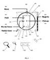
- FIG. 1is a graphical representation illustrating the geometry for constructing a three-dimensional perspective viewing frustum, relative to an x, y, z coordinate system, in accordance with elastic presentation space graphics technology;
- FIG. 2is a graphical representation illustrating the geometry of a presentation in accordance with elastic presentation space graphics technology
- FIG. 3is a block diagram illustrating a data processing system adapted to implement an embodiment of the invention
- FIG. 4is a partial screen capture illustrating a GUI having lens control elements for user interaction with detail-in-context data presentations
- FIG. 5is a diagram illustrating an original configuration of a 2D cross-sectional view of a structure
- FIG. 5Ais a diagram illustrating extrusion of points on the surface of the object-of-interest along a path toward a viewpoint.
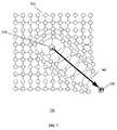
- FIG. 6is a diagram illustrating direction vectors to points in the structure of FIG. 5 lying on or near a sight-line;
- FIG. 7is a diagram illustrating a final configuration resulting from the application of an occlusion reducing transformation function to the structure of FIG. 5 ;
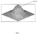
- FIG. 8is a diagram illustrating a distortion function or lens
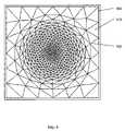
- FIG. 9is a diagram illustrating an original image or representation in the form of a mesh composed of polygons (e.g., triangles);
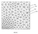
- FIG. 10is a detail view of a portion of the mesh of FIG. 9 ;
- FIG. 11is a flow chart illustrating operations of software modules within the memory of a data processing system for generating a presentation of a region-of-interest in an original image for display on a display screen, the original image being a collection of polygons having polygons defined by three or more shared edges joined at vertex points, in accordance with an embodiment of the invention.
- data processing systemis used herein to refer to any machine for processing data, including the navigation systems, computer systems, and network arrangements described herein.
- the present inventionmay be implemented in any computer programming language provided that the operating system of the data processing system provides the facilities that may support the requirements of the present invention. Any limitations presented would be a result of a particular type of operating system or computer programming language and would not be a limitation of the present invention.
- the “screen real estate problem”generally arises whenever large amounts of information are to be displayed on a display screen of limited size.
- Known tools to address this probleminclude panning and zooming. While these tools are suitable for a large number of visual display applications, they become less effective where sections of the visual information are spatially related, such as in layered maps and three-dimensional representations, for example. In this type of information display, panning and zooming are not as effective as much of the context of the panned or zoomed display may be hidden.
- Detail-in-contextis the magnification of a particular region-of-interest (the “focal region” or “detail”) in a data presentation while preserving visibility of the surrounding information (the “context”).
- This techniquehas applicability to the display of large surface area media (e.g. digital maps) on computer screens of variable size including graphics workstations, laptop computers, personal digital assistants (“PDAs”), and cell phones.
- PDAspersonal digital assistants
- a representationis a formal system, or mapping, for specifying raw information or data that is stored in a computer or data processing system.
- a digital map of a cityis a representation of raw data including street names and the relative geographic location of streets and utilities. Such a representation may be displayed visually on a computer screen or printed on paper.
- a presentationis a spatial organization of a given representation that is appropriate for the task at hand.
- a presentation of a representationorganizes such things as the point of view and the relative emphasis of different parts or regions of the representation. For example, a digital map of a city may be presented with a region magnified to reveal street names.
- a detail-in-context presentationmay be considered as a distorted view (or distortion) of a portion of the original representation or image where the distortion is the result of the application of a “lens” like distortion function to the original representation.
- EPSElastic Presentation Space
- PDTPliable Display Technology
- detail-in-context data presentationsare characterized by magnification of areas of an image where detail is desired, in combination with compression of a restricted range of areas of the remaining information (i.e. the context), the result typically giving the appearance of a lens having been applied to the display surface.
- points in a representationare displaced in three dimensions and a perspective projection is used to display the points on a two-dimensional presentation display.
- the resulting presentationappears to be three-dimensional.
- the lens transformationappears to have stretched the continuous surface in a third dimension.
- EPS graphics technologya two-dimensional visual representation is placed onto a surface; this surface is placed in three-dimensional space; the surface, containing the representation, is viewed through perspective projection; and the surface is manipulated to effect the reorganization of image details.
- the presentation transformationis separated into two steps: surface manipulation or distortion and perspective projection.
- FIG. 1is a graphical representation illustrating the geometry 100 for constructing a three-dimensional (“3D”) perspective viewing frustum 220 , relative to an x, y, z coordinate system, in accordance with elastic presentation space (EPS) graphics technology.
- EPSelastic presentation space
- 2Dtwo-dimensional
- EPSmagnification of regions of interest and the accompanying compression of the contextual region to accommodate this change in scale are produced by the movement of regions of the surface towards the viewpoint (“VP”) 240 located at the apex of the pyramidal shape 220 containing the frustum.
- the process of projecting these transformed layouts via a perspective projectionresults in a new 2D layout which includes the zoomed and compressed regions.
- the use of the third dimension and perspective distortion to provide magnification in EPSprovides a meaningful metaphor for the process of distorting the information presentation surface.
- the 3D manipulation of the information presentation surface in such a systemis an intermediate step in the process of creating a new 2D layout of the information.
- FIG. 2is a graphical representation illustrating the geometry 200 of a presentation in accordance with EPS graphics technology.
- EPS graphics technologyemploys viewer-aligned perspective projections to produce detail-in-context presentations in a reference view plane 201 which may be viewed on a display.
- Undistorted 2D data pointsare located in a basal plane 210 of a 3D perspective viewing volume or frustum 220 which is defined by extreme rays 221 and 222 and the basal plane 210 .
- the VP 240is generally located above the centre point of the basal plane 210 and reference view plane (“RVP”) 201 . Points in the basal plane 210 are displaced upward onto a distorted surface 230 which is defined by a general 3D distortion function (i.e.
- the direction of the perspective projection corresponding to the distorted surface 230is indicated by the line FPo-FP 231 drawn from a point FPo 232 in the basal plane 210 through the point FP 233 which corresponds to the focus or focal region or focal point of the distorted surface 230 .
- the perspective projectionhas a direction 231 that is viewer-aligned (i.e., the points FPo 232 , FP 233 , and VP 240 are collinear).
- EPSis applicable to multidimensional data and is well suited to implementation on a computer for dynamic detail-in-context display on an electronic display surface such as a monitor.
- EPSis typically characterized by magnification of areas of an image where detail is desired 233 , in combination with compression of a restricted range of areas of the remaining information (i.e. the context) 234 , the end result typically giving the appearance of a lens 230 having been applied to the display surface.
- the areas of the lens 230 where compression occursmay be referred to as the “shoulder” 234 of the lens 230 .
- the area of the representation transformed by the lensmay be referred to as the “lensed area”.
- the lensed areathus includes the focal region and the shoulder.
- the source image or representation to be viewedis located in the basal plane 210 .
- Magnification 233 and compression 234are achieved through elevating elements of the source image relative to the basal plane 210 , and then projecting the resultant distorted surface onto the reference view plane 201 .
- EPSperforms detail-in-context presentation of n-dimensional data through the use of a procedure wherein the data is mapped into a region in an (n+1) dimensional space, manipulated through perspective projections in the (n+1) dimensional space, and then finally transformed back into n-dimensional space for presentation.
- EPShas numerous advantages over conventional zoom, pan, and scroll technologies, including the capability of preserving the visibility of information outside 234 the local region of interest 233 .
- EPScan be implemented through the projection of an image onto a reference plane 201 in the following manner.
- the source image or representationis located on a basal plane 210 , and those regions of interest 233 of the image for which magnification is desired are elevated so as to move them closer to a reference plane situated between the reference viewpoint 240 and the reference view plane 201 .
- Magnification of the focal region 233 closest to the RVP 201varies inversely with distance from the RVP 201 . As shown in FIGS.
- compression of regions 234 outside the focal region 233is a function of both distance from the RVP 201 , and the gradient of the function describing the vertical distance from the RVP 201 with respect to horizontal distance from the focal region 233 .
- the resultant combination of magnification 233 and compression 234 of the image as seen from the reference viewpoint 240results in a lens-like effect similar to that of a magnifying glass applied to the image.
- the various functions used to vary the magnification and compression of the source image via vertical displacement from the basal plane 210are described as lenses, lens types, or lens functions. Lens functions that describe basic lens types with point and circular focal regions, as well as certain more complex lenses and advanced capabilities such as folding, have previously been described by Carpendale.
- FIG. 3is a block diagram illustrating a data processing system 300 adapted to implement an embodiment of the invention.
- the data processing system 300is suitable for implementing EPS technology, for displaying detail-in-context presentations of representations in conjunction with a detail-in-context graphical user interface (“GUI”) 400 , as described below, and for controlling detail-in-context lenses in detail-in-context presentations while reducing occlusion and improving magnification.
- the data processing system 300includes an input device 310 , a central processing unit (“CPU”) 320 , memory 330 , and a display 340 .
- the input device 310may include a keyboard, a mouse, a trackball, an eye tracking device, a position tracking device, or a similar device.
- the CPU 320may include dedicated coprocessors and memory devices.
- the memory 330may include RAM, ROM, databases, or disk devices.
- the display 340may include a computer screen, terminal device, or a hardcopy producing output device such as a printer or plotter.
- the data processing system 300has stored therein data representing sequences of instructions which when executed cause the method described herein to be performed.
- the data processing system 300may contain additional software and hardware a description of which is not necessary for understanding the invention.
- the data processing system 300includes computer executable programmed instructions for directing the system 300 to implement the embodiments of the present invention.
- the programmed instructionsmay be embodied in one or more software modules 331 resident in the memory 330 of the data processing system 300 .
- the programmed instructionsmay be embodied on a computer readable medium (such as a CD disk or floppy disk) which may be used for transporting the programmed instructions to the memory 330 of the data processing system 300 .
- the programmed instructionsmay be embedded in a computer-readable, signal-bearing medium that is uploaded to a network by a vendor or supplier of the programmed instructions, and this signal-bearing medium may be downloaded through an interface to the data processing system 300 from the network by end users or potential buyers.
- detail-in-context presentations of data using techniques such as pliable surfaces, as described by Carpendale,are useful in presenting large amounts of information on limited-size display surfaces.
- Detail-in-context viewsallow magnification of a particular region-of-interest (the “focal region”) 233 in a data presentation while preserving visibility of the surrounding information 210 .
- a GUI 400is described having lens control elements that can be implemented in software and applied to the editing of multi-layer images and to the control of detail-in-context data presentations.
- the softwarecan be loaded into and run by the data processing system 300 of FIG. 3 .
- applications in computer graphics systemsare launched by the computer graphics system's operating system upon selection by a user from a menu or other GUI.
- a GUIis used to convey information to and receive commands from users and generally includes a variety of GUI objects or controls, including icons, toolbars, drop-down menus, text, dialog boxes, buttons, and the like.
- a usertypically interacts with a GUI by using a pointing device (e.g., a mouse) to position a pointer or cursor over an object and “clicking” on the object.
- a pointing devicee.g., a mouse
- FIG. 4is a partial screen capture illustrating a GUI 400 having lens control elements for user interaction with detail-in-context data presentations.
- Detail-in-context data presentationsare characterized by magnification of areas of an image where detail is desired, in combination with compression of a restricted range of areas of the remaining information (i.e. the context), the end result typically giving the appearance of a lens having been applied to the display screen surface.
- This lens 410includes a “focal region” 420 having high magnification, a surrounding “shoulder region” 430 where information is typically visibly compressed, and a “base” 412 surrounding the shoulder region 430 and defining the extent of the lens 410 .
- FIG. 4is a partial screen capture illustrating a GUI 400 having lens control elements for user interaction with detail-in-context data presentations.
- Detail-in-context data presentationsare characterized by magnification of areas of an image where detail is desired, in combination with compression of a restricted range of areas of the remaining information (i.e. the context), the
- the lens 410is shown with a circular shaped base 412 (or outline) and with a focal region 420 lying near the center of the lens 410 .
- the lens 410 and focal region 420may have any desired shape.
- the base of the lens 412may be coextensive with the focal region 420 .
- the GUI 400has lens control elements that, in combination, provide for the interactive control of the lens 410 .
- the effective control of the characteristics of the lens 410 by a useri.e., dynamic interaction with a detail-in-context lens
- one or more of these lens control elementsmay be made visible to the user on the display surface 340 by appearing as overlay icons on the lens 410 .
- Interaction with each elementis performed via the motion of an input or pointing device 310 (e.g., a mouse) with the motion resulting in an appropriate change in the corresponding lens characteristic.
- selection of which lens control element is actively controlled by the motion of the pointing device 310 at any given timeis determined by the proximity of the icon representing the pointing device 310 (e.g. cursor) on the display surface 340 to the appropriate component of the lens 410 .
- the icon representing the pointing device 310e.g. cursor
- “dragging” of the pointing device at the periphery of the bounding rectangle of the lens base 412causes a corresponding change in the size of the lens 410 (i.e. “resizing”).
- the GUI 400provides the user with a visual representation of which lens control element is being adjusted through the display of one or more corresponding icons.
- pointing device 310that is a mouse
- 2D or 3D (or even greater numbers of dimensions) pointing devicesincluding a trackball, a keyboard, an eye tracking device, and a position tracking device.
- a mouse 310controls the position of a cursor icon 401 that is displayed on the display screen 340 .
- the cursor 401is moved by moving the mouse 310 over a flat surface, such as the top of a desk, in the desired direction of movement of the cursor 401 .
- a flat surfacesuch as the top of a desk
- the two-dimensional movement of the mouse 310 on the flat surfacetranslates into a corresponding two-dimensional movement of the cursor 401 on the display screen 340 .
- a mouse 310typically has one or more finger actuated control buttons (i.e. mouse buttons). While the mouse buttons can be used for different functions such as selecting a menu option pointed at by the cursor 401 , the disclosed invention may use a single mouse button to “select” a lens 410 and to trace the movement of the cursor 401 along a desired path. Specifically, to select a lens 410 , the cursor 401 is first located within the extent of the lens 410 . In other words, the cursor 401 is “pointed” at the lens 410 . Next, the mouse button is depressed and released. That is, the mouse button is “clicked”. Selection is thus a point and click operation.
- the mouse buttonis depressed and released. That is, the mouse button is “clicked”. Selection is thus a point and click operation.
- the cursor 401is located at the desired starting location, the mouse button is depressed to signal the computer 320 to activate a lens control element, and the mouse 310 is moved while maintaining the button depressed. After the desired path has been traced, the mouse button is released.
- This procedureis often referred to as “clicking” and “dragging” (i.e. a click and drag operation). It will be understood that a predetermined key on a keyboard 310 could also be used to activate a mouse click or drag.
- clickingwill refer to the depression of a mouse button indicating a selection by the user and the term “dragging” will refer to the subsequent motion of the mouse 310 and cursor 401 without the release of the mouse button.
- the GUI 400may include the following lens control elements: move, pickup, resize base, resize focus, fold, magnify, zoom, and scoop. Each of these lens control elements has at least one lens control icon or alternate cursor icon associated with it.
- the following lens control iconsmay be displayed over the lens 410 : pickup icon 450 , base outline icon 412 , base bounding rectangle icon 411 , focal region bounding rectangle icon 421 , handle icons 481 , 482 , 491 magnify slide bar icon 440 , zoom icon 495 , and scoop slide bar icon (not shown).
- these iconsare displayed simultaneously after selection of the lens 410 .
- an alternate cursor icon 460 , 470 , 480 , 490 , 495may be displayed over the lens 410 to replace the cursor 401 or may be displayed in combination with the cursor 401 .
- bounding rectangle icons 411 , 421are displayed surrounding the base 412 and focal region 420 of the selected lens 410 to indicate that the lens 410 has been selected.
- bounding rectangles 411 , 421one might view them as glass windows enclosing the lens base 412 and focal region 420 , respectively.
- the bounding rectangles 411 , 421include handle icons 481 , 482 , 491 allowing for direct manipulation of the enclosed base 412 and focal region 420 as will be explained below.
- the bounding rectangles 411 , 421not only inform the user that the lens 410 has been selected, but also provide the user with indications as to what manipulation operations might be possible for the selected lens 410 though use of the displayed handles 481 , 482 , 491 .
- a bounding region having a shape other than generally rectangularSuch a bounding region could be of any of a great number of shapes including oblong, oval, ovoid, conical, cubic, cylindrical, polyhedral, spherical, etc.
- the cursor 401provides a visual cue indicating the nature of an available lens control element. As such, the cursor 401 will generally change in form by simply pointing to a different lens control icon 450 , 412 , 411 , 421 , 481 , 482 , 491 , 440 . For example, when resizing the base 412 of a lens 410 using a corner handle 491 , the cursor 401 will change form to a resize icon 490 once it is pointed at (i.e. positioned over) the corner handle 491 . The cursor 401 will remain in the form of the resize icon 490 until the cursor 401 has been moved away from the corner handle 491 .
- Lateral movement of a lens 410is provided by the move lens control element of the GUI 400 .
- This functionalityis accomplished by the user first selecting the lens 410 through a point and click operation. Then, the user points to a point within the lens 410 that is other than a point lying on a lens control icon 450 , 412 , 411 , 421 , 481 , 482 , 491 , 440 .
- a move icon 460is displayed over the lens 410 to replace the cursor 401 or may be displayed in combination with the cursor 401 .
- the move icon 460not only informs the user that the lens 410 may be moved, but also provides the user with indications as to what movement operations are possible for the selected lens 410 .
- the move icon 460may include arrowheads indicating up, down, left, and right motion.
- the lens 410is moved by a click and drag operation in which the user clicks and drags the lens 410 to the desired position on the screen 340 and then releases the mouse button 310 .
- the lens 410is locked in its new position until a further pickup and move operation is performed.
- Lateral movement of a lens 410is also provided by the pickup lens control element of the GUI. This functionality is accomplished by the user first selecting the lens 410 through a point and click operation. As mentioned above, when the lens 410 is selected a pickup icon 450 is displayed over the lens 410 near the centre of the lens 410 . Typically, the pickup icon 450 will be a crosshairs. In addition, a base outline 412 is displayed over the lens 410 representing the base 412 of the lens 410 . The crosshairs 450 and lens outline 412 not only inform the user that the lens has been selected, but also provides the user with an indication as to the pickup operation that is possible for the selected lens 410 . Next, the user points at the crosshairs 450 with the cursor 401 .
- the lens outline 412is moved by a click and drag operation in which the user clicks and drags the crosshairs 450 to the desired position on the screen 340 and then releases the mouse button 310 .
- the full lens 410is then moved to the new position and is locked there until a further pickup operation is performed.
- Resizing of the base 412 (or outline) of a lens 410is provided by the resize base lens control element of the GUI.
- a bounding rectangle icon 411is displayed surrounding the base 412 .
- the bounding rectangle icon 411may be coextensive with the perimeter of the base 412 .
- the bounding rectangle 411includes handles 491 . These handles 491 can be used to stretch the base 412 taller or shorter, wider or narrower, or proportionally larger or smaller.
- the corner handles 491will keep the proportions the same while changing the size.
- the middle handles(not shown) will make the base 412 taller or shorter, wider or narrower.
- Resizing the base 412 by the corner handles 491will keep the base 412 in proportion. Resizing the base 412 by the middle handles will change the proportions of the base 412 . That is, the middle handles change the aspect ratio of the base 412 (i.e. the ratio between the height and the width of the bounding rectangle 411 of the base 412 ).
- a resize icon 490may be displayed over the handle 491 to replace the cursor 401 or may be displayed in combination with the cursor 401 .
- the resize icon 490not only informs the user that the handle 491 may be selected, but also provides the user with indications as to the resizing operations that are possible with the selected handle.
- the resize icon 490 for a corner handle 491may include arrows indicating proportional resizing.
- the resize icon (not shown) for a middle handlemay include arrows indicating width resizing or height resizing.
- Resizing of the focal region 420 of a lens 410is provided by the resize focus lens control element of the GUI.
- a bounding rectangle icon 421is displayed surrounding the focal region 420 .
- the bounding rectangle icon 421may be coextensive with the perimeter of the focal region 420 .
- the bounding rectangle 421includes handles 481 , 482 . These handles 481 , 482 can be used to stretch the focal region 420 taller or shorter, wider or narrower, or proportionally larger or smaller.
- the corner handles 481will keep the proportions the same while changing the size.
- the middle handles 482will make the focal region 420 taller or shorter, wider or narrower.
- Resizing the focal region 420 by the corner handles 481will keep the focal region 420 in proportion. Resizing the focal region 420 by the middle handles 482 will change the proportions of the focal region 420 . That is, the middle handles 482 change the aspect ratio of the focal region 420 (i.e. the ratio between the height and the width of the bounding rectangle 421 of the focal region 420 ).
- a resize icon 480may be displayed over the handle 481 , 482 to replace the cursor 401 or may be displayed in combination with the cursor 401 .
- the resize icon 480not only informs the user that a handle 481 , 482 may be selected, but also provides the user with indications as to the resizing operations that are possible with the selected handle.
- the resize icon 480 for a corner handle 481may include arrows indicating proportional resizing.
- the resize icon 480 for a middle handle 482may include arrows indicating width resizing or height resizing.
- Folding of the focal region 420 of a lens 410is provided by the fold control element of the GUI.
- control of the degree and direction of foldingi.e. skewing of the viewer aligned vector 231 as described by Carpendale
- the direction of foldingis determined by the direction in which the point 471 is dragged.
- the degree of foldingis determined by the magnitude of the translation of the cursor 401 during the drag.
- the direction and degree of foldingcorresponds to the relative displacement of the focus 420 with respect to the lens base 410 . In other words, and referring to FIG.
- the direction and degree of foldingcorresponds to the displacement of the point FP 233 relative to the point FPo 232 , where the vector joining the points FPo 232 and FP 233 defines the viewer aligned vector 231 .
- a bounding rectangle icon 421is displayed surrounding the focal region 420 .
- the bounding rectangle 421includes handles 481 , 482 .
- a fold icon 470may be displayed over the point 471 to replace the cursor 401 or may be displayed in combination with the cursor 401 .
- the fold icon 470not only informs the user that a point 471 on the bounding rectangle 421 may be selected, but also provides the user with indications as to what fold operations are possible.
- the fold icon 470may include arrowheads indicating up, down, left, and right motion.
- Magnification of the lens 410is provided by the magnify lens control element of the GUI.
- the magnify controlis presented to the user as a slide bar icon 440 near or adjacent to the lens 410 and typically to one side of the lens 410 .
- Sliding the bar 441 of the slide bar 440results in a proportional change in the magnification of the lens 410 .
- the slide bar 440not only informs the user that magnification of the lens 410 may be selected, but also provides the user with an indication as to what level of magnification is possible.
- the slide bar 440includes a bar 441 that may be slid up and down, or left and right, to adjust and indicate the level of magnification.
- the userwould click on the bar 441 of the slide bar 440 and drag in the direction of desired magnification level. Once the desired level of magnification is reached, the user would release the mouse button 310 .
- the lens 410is then locked with the selected magnification until a further magnification operation is performed.
- the focal region 420is an area of the lens 410 having constant magnification (i.e. if the focal region is a plane). Again referring to FIGS. 1 and 2 , magnification of the focal region 420 , 233 varies inversely with the distance from the focal region 420 , 233 to the reference view plane (RVP) 201 .
- RVPreference view plane
- Magnification of areas lying in the shoulder region 430 of the lens 410also varies inversely with their distance from the RVP 201 .
- magnification of areas lying in the shoulder region 430will range from unity at the base 412 to the level of magnification of the focal region 420 .
- Zoom functionalityis provided by the zoom lens control element of the GUI.
- the zoom lens control elementallows a user to quickly navigate to a region of interest 233 within a continuous view of a larger presentation 210 and then zoom in to that region of interest 233 for detailed viewing or editing.
- the combined presentation area covered by the focal region 420 and shoulder region 430 and surrounded by the base 412may be referred to as the “extent of the lens”.
- the presentation area covered by the focal region 420may be referred to as the “extent of the focal region”.
- the extent of the lensmay be indicated to a user by a base bounding rectangle 411 when the lens 410 is selected.
- the extent of the lensmay also be indicated by an arbitrarily shaped figure that bounds or is coincident with the perimeter of the base 412 .
- the extent of the focal regionmay be indicated by a second bounding rectangle 421 or arbitrarily shaped figure.
- the zoom lens control elementallows a user to: (a) “zoom in” to the extent of the focal region such that the extent of the focal region fills the display screen 340 (i.e. “zoom to focal region extent”); (b) “zoom in” to the extent of the lens such that the extent of the lens fills the display screen 340 (i.e. “zoom to lens extent”); or, (c) “zoom in” to the area lying outside of the extent of the focal region such that the area without the focal region is magnified to the same level as the extent of the focal region (i.e. “zoom to scale”).
- a bounding rectangle icon 411is displayed surrounding the base 412 and a bounding rectangle icon 421 is displayed surrounding the focal region 420 .
- Zoom functionalityis accomplished by the user first selecting the zoom icon 495 through a point and click operation
- a zoom cursor icon 496may be displayed to replace the cursor 401 or may be displayed in combination with the cursor 401 .
- the zoom cursor icon 496provides the user with indications as to what zoom operations are possible.
- the zoom cursor icon 496may include a magnifying glass.
- zoom to focal region extentsuch that the extent of the focal region fills the display screen 340
- zoom to lens extentTo zoom in to the extent of the lens such that the extent of the lens fills the display screen 340 (i.e. “zoom to lens extent”), the user would point and click within the extent of the lens.
- zoom in to the presentation area without the extent of the focal regionsuch that the area without the extent of the focal region is magnified to the same level as the extent of the focal region (i.e. “zoom to scale”), the user would point and click without the extent of the lens.
- the presentationis locked with the selected zoom until a further zoom operation is performed.
- a zoom function menu with multiple items (not shown) or multiple zoom function icons (not shown)may be used for zoom function selection.
- the zoom function menumay be presented as a pull-down menu.
- the zoom function iconsmay be presented in a toolbar or adjacent to the lens 410 when the lens is selected.
- Individual zoom function menu items or zoom function iconsmay be provided for each of the “zoom to focal region extent”, “zoom to lens extent”, and “zoom to scale” functions described above.
- a bounding rectangle icon 411may be displayed surrounding the base 412 and a bounding rectangle icon 421 may be displayed surrounding the focal region 420 .
- Zoom functionalityis accomplished by the user selecting a zoom function from the zoom function menu or via the zoom function icons using a point and click operation. In this way, a zoom function may be selected without considering the position of the cursor 401 within the lens 410 .
- the concavity or “scoop” of the shoulder region 430 of the lens 410is provided by the scoop lens control element of the GUI.
- the scoop controlis presented to the user as a slide bar icon (not shown) near or adjacent to the lens 410 and typically below the lens 410 . Sliding the bar (not shown) of the slide bar results in a proportional change in the concavity or scoop of the shoulder region 430 of the lens 410 .
- the slide barnot only informs the user that the shape of the shoulder region 430 of the lens 410 may be selected, but also provides the user with an indication as to what degree of shaping is possible.
- the slide barincludes a bar (not shown) that may be slid left and right, or up and down, to adjust and indicate the degree of scooping.
- a bar(not shown) that may be slid left and right, or up and down, to adjust and indicate the degree of scooping.
- the userwould click on the bar of the slide bar and drag in the direction of desired scooping degree. Once the desired degree of scooping is reached, the user would release the mouse button 310 .
- the lens 410is then locked with the selected scoop until a further scooping operation is performed.
- a usermay choose to hide one or more lens control icons 450 , 412 , 411 , 421 , 481 , 482 , 491 , 440 , 495 shown in FIG. 4 from view so as not to impede the user's view of the image within the lens 410 .
- Thismay be helpful, for example, during an editing or move operation.
- a usermay select this option through means such as a menu, toolbar, or lens property dialog box.
- GUI 400maintains a record of control element operations such that the user may restore pre-operation presentations.
- This record of operationsmay be accessed by or presented to the user through “Undo” and “Redo” icons 497 , 498 , through a pull-down operation history menu (not shown), or through a toolbar.
- detail-in-context data viewing techniquesallow a user to view multiple levels of detail or resolution on one display 340 .
- the appearance of the data display or presentationis that of one or more virtual lenses showing detail 233 within the context of a larger area view 210 .
- Using multiple lenses in detail-in-context data presentationsmay be used to compare two regions of interest at the same time. Folding enhances this comparison by allowing the user to pull the regions of interest closer together.
- detail-in-context technologysuch as PDT
- an area of interestcan be magnified to pixel level resolution, or to any level of detail available from the source information, for in-depth review.
- the digital imagesmay include graphic images, maps, photographic images, or text documents, and the source information may be in raster, vector, or text form.
- a usercan define a lens 410 over the object using the GUI 400 .
- the lens 410may be introduced to the original image to form the a presentation through the use of a pull-down menu selection, tool bar icon, etc.
- lens control elements for the GUI 400such as move, pickup, resize base, resize focus, fold, magnify, zoom, and scoop, as described above, the user adjusts the lens 410 for detailed viewing of the object or area.
- the magnify lens control elementfor example, the user may magnify the focal region 420 of the lens 410 to pixel quality resolution revealing detailed information pertaining to the selected object or area.
- a base imagei.e., the image outside the extent of the lens
- a lens imagei.e., the image within the extent of the lens
- the data processing system 300employs EPS techniques with an input device 310 and GUI 400 for selecting objects or areas for detailed display to a user on a display screen 340 .
- Data representing an original image or representationis received by the CPU 320 of the data processing system 300 .
- the CPU 320processes the data in accordance with instructions received from the user via an input device 310 and GUI 400 to produce a detail-in-context presentation. The presentation is presented to the user on a display screen 340 . It will be understood that the CPU 320 may apply a transformation to the shoulder region 430 surrounding the region-of-interest 420 to affect blending or folding in accordance with EPS technology.
- the transformationmay map the region-of-interest 420 and/or shoulder region 430 to a predefined lens surface, defined by a transformation or distortion function and having a variety of shapes, using EPS techniques.
- the lens 410may be simply coextensive with the region-of-interest 420 .
- the lens control elements of the GUI 400are adjusted by the user via an input device 310 to control the characteristics of the lens 410 in the detail-in-context presentation.
- an input device 310such as a mouse
- a useradjusts parameters of the lens 410 using icons and scroll bars of the GUI 400 that are displayed over the lens 410 on the display screen 340 .
- the usermay also adjust parameters of the image of the full scene.
- Signals representing input device 310 movements and selectionsare transmitted to the CPU 320 of the data processing system 300 where they are translated into instructions for lens control.
- the lens 410may be added to the presentation before or after the object or area is selected. That is, the user may first add a lens 410 to a presentation or the user may move a pre-existing lens into place over the selected object or area.
- the lens 410may be introduced to the original image to form the presentation through the use of a pull-down menu selection, tool bar icon, etc.
- a usercan view a large area (i.e., outside the extent of the lens 410 ) while focusing in on a smaller area (or within the focal region 420 of the lens 410 ) surrounding the selected object. This makes it possible for a user to accurately gather detailed information without losing visibility or context of the portion of the original image surrounding the selected object.
- FIGS. 5-7show 2D cross-sectional views of a linear occlusion reducing transformation in operation.
- FIG. 5is a diagram illustrating an original configuration 500 of the 2D cross-sectional view of a structure 510 .
- the structure 510is defined by a number of information points 501 arranged in a matrix.
- a region-of-interest (or an object-of-interest) 520is shown near the centre of the structure 510 .
- a viewpoint 530 for the region-of-interest 520is shown near the bottom right-hand side of the structure 510 .
- a sight-line 540connects the region-of-interest 520 to the viewpoint 530 . In other words, the region-of-interest 520 and the viewpoint 530 define the line of sight through the structure 510 .
- FIG. 5Ais a diagram illustrating extrusion of points on the object-of-interest (illustrated as lines 502 , 504 extending from the object-of-interest 520 ) along the path, such as the sight-line 540 , toward the viewpoint 530 .
- the extrusions, represented as lines 502 , 504form a volume that may be used to determine minimum displacements from the path for objects intersected by the volume.
- objects that occlude the object-of-interestmay be displaced away from the path.
- the points 501 intersected by the lines 502 , 504 or lying within the volume formed by lines 502 , 504may be displaced away from the sight-line 540 according to a transformation function and the minimum displacements to locations within the original image, such as shown in FIG. 6 .
- FIG. 6is a diagram illustrating direction vectors 650 to points 670 in the structure 510 of FIG. 5 lying on or near the sight-line 540 .
- the distance of each point 670is measured to the nearest point 660 on the sight-line 540 .
- a direction vector 650 from the nearest point 660 on the sight-line 540 to the point being adjusted 670is also determined.
- pointswill be moved in the direction of these direction vectors 650 .
- the lengths of the direction vectors 650form an input to a transformation function. The result of this function is used to determine the displacement for each point. Points closest to the line of sight are moved the furthest in distance, and points originally lying further away are moved in successively smaller increments in distance.
- the lengths of the direction vectors 650form inputs to the function that determines the magnitude of resulting displacement vectors.
- the direction of the resulting displacement vectorswill be parallel to the input direction vectors. Eventually a smooth transition is made to points which are far enough away as to be unaffected by the transformation.
- FIG. 7is a diagram illustrating a final configuration 700 resulting from the application of the occlusion reducing transformation function to the structure 510 of FIG. 5 .
- this final configuration 700a clear line of sight from the viewpoint 530 to the region-of-interest 520 is established.
- the effect of an occlusion reducing transformationis to provide a clear line of sight, or visual access, to an object or region-of-interest within a 3D visual representation by adjusting the layout.
- the amplitude of displacementsis increased until an extrusion of the object of interest 520 toward the viewpoint 530 does not intersect any other objects (e.g., 550 in FIG. 5 ).
- This extrusion testcan be performed, for example, by projecting any point or locus of points on the object 520 in a direction towards the viewpoint 530 . If this projection yields no intersections with other objects 550 , then the line of sight 540 can be considered to be cleared, and the minimum magnitude of the occlusion reduction displacements has been achieved.
- This criterionprovides a means of testing whether a given displacement operation or other occlusion reduction method has resulted in the elimination or reduction of occlusion.
- the extrusion of all object points in this mannerdefines a volume which must be cleared of obstructions for the complete elimination or reduction of occlusion.
- such an extrusion coupled with the orthogonal displacement as described above from U.S. Pat. No. 6,798,412defines a minimum displacement from the line of sight 540 and hence an optimal occlusion reduction.
- FIG. 8is a diagram illustrating a distortion function 230 or lens 410 .
- the lens 410may be adjusted with the GUI 400 of FIG. 4 .
- FIG. 9is a diagram illustrating an original image or representation in the form of a mesh 900 composed of polygons (e.g., triangles) 910 .
- FIG. 10is a detail view of a portion of the mesh 900 of FIG. 9 .
- the lens 410is defined by a distortion function 230 that is a Gaussian function.
- the mesh 900 of FIG. 9is fitted to the distortion function 230 or lens 410 of FIG.
- the mesh 900is aligned to the Hessian of the Gaussian function (i.e., the polygons near the centre of the mesh 900 are smaller in size than those near the outer edges of the mesh).
- the mesh 900may have polygons 910 that are not pre-fitted to the lens 410 .
- the application of a lens 410 to an original imagemay be simplified as in general only the vertices 920 of each polygon 910 need be displaced. Points lying between the vertices 920 may then be interpolated.
- the method described here with respect to FIGS. 8-10is one approach of generating a random looking mesh in the hope that it will closely approximate a lens. What will be described next is an improved methodical approach to meshing a polygon.
- one or multiple vertices 920may lie within the lens 410 , under which circumstance those vertices 920 would be displaced, but the connecting edges 930 would remain straight, not curved according to the geometry specified by the lens 410 .
- the solution to these problems provided by the present inventionis to subdivide triangles 910 that intersect the lens 410 in such a way that the displaced triangles will adequately approximate the distortion specified by the lens 410 . This is accomplished by inserting extra vertices 920 and edges 930 into the triangle geometry 900 .
- a circle of edges 930 around the bounds or perimeter (e.g., 411 or 412 ) of the lens 410 , one around the focal bounds or perimeter (e.g., 421 ) of the lens 410 , and possibly one or more at intermediate points (e.g., 430 ) in between the focal region 420 and the bounds 411 , 412is inserted.
- additional edges 930 and vertices 920may be inserted radially from the center of the lens 410 , like bicycle spokes, to improve the appearance of the lens 410 .
- FIGS. 9 and 10may be described as illustrating a “collection of polygons” 900 rather than a mesh composed of polygons. For example, in the case of a CAD drawing with multiple parts, there could be a separate mesh or collection of polygons associated with each part.
- data vertices 920can be located anywhere in the 3D space. This affects the manner in which a detail-in-context presentation for an original 3D image is generated.
- the lense.g., 230 in FIG. 2
- the lensis defined as existing in the plane 210 of the original image or data.
- an arbitrary planeis chosen on which the lens 410 may be defined.
- the arbitrary planecan be chosen to be orthogonal to the line of sight (e.g., 231 in FIG. 2 ).
- the lenscan be defined on the arbitrary plane and then projected onto a view plane (e.g., 201 in FIG. 2 ) or screen to achieve a desired size or magnification.
- a first stepis project the perimeter of the lens 411 , 412 and/or focal region 421 onto the arbitrary plane.
- This projectionmay be a perspective projection or an orthonormal projection.
- the resulting collection of polygonsare displaced onto the lens 410 and perspectively projected onto a view plane in a viewpoint aligned direction.
- occlusion reductioncan also be performed with an orthonormal camera projection.
- an orthonormal projectionfirst, an arbitrary perspective projection is used with a standard displacement function (as described above), second, the point to be displaced is translated onto the lens surface, and third, the point is perspectively projected onto the desired plane. The difference between this new point and the original point is what is used for the displacement in an orthonormal projection.
- a method for providing a lens-dependent level of detail in a presentationis provided.
- 3D modelscan sometimes be very complex, taxing the processor 320 and memory 330 subsystems of a data processing system 300 . Reducing model complexity can help deal with this problem.
- Coupling level of detail with lens positioncan be used to keep polygon count in a mesh 900 low, while still providing high polygon counts where they are needed.
- the low level polygon count modelscan be arrived at in several ways.
- a usercan explicitly specify a simple geometry version of a complex assembly.
- the rendering software 331may be instructed to replace a complex engine assembly in a representation of an automobile with a simple cylinder assembly.
- the rendering software 331can use automated model simplification algorithms to arrive at simpler models, provided that these algorithms themselves are not excessively computationally expensive.
- 3D magnification lenses and a method for occlusion reduction with magnificationare provided.
- detail-in-context lens magnificationas described in U.S. Pat. Nos. 6,768,497 and 6,798,412 and U.S. patent application Ser. Nos. 10/021,313, 10/137,648, and 10/166,736, which are incorporated herein by reference, is extended to magnification of 3D objects. Algorithmically, there are several methods of providing this.
- One methodis to project 3D data vertices onto a plane perpendicular to the line of sight, apply a 2D lens to the vertices (e.g., 920 ) in the plane, and then “un-project” the vertices back into 3D.
- An occlusion reduction operation for the magnified objectcan then be applied after the magnification step (i.e., the application of the 2D lens).
- the un-project stepmay be performed in two ways.
- the first methodis to translate the lensed point along a line specified by the viewpoint and the lensed point, a distance equal to the distance of the original projection.
- the direction of translationis opposite to the original projection.
- the second methodis the same as the first, except the distance of the translation is calculated such that the point will be co-planar with the original data vertex point, with the plane defined as being perpendicular to the line of sight.
- a method for selective and automatic occlusion reduction based on object recognition or object attributesis provided.
- pattern recognition or object recognition methodsare used to automatically detect specific objects (e.g., 550 in FIG. 5 ) and apply known constraints to their allowed displacements.
- an object of interestmay be recognized by querying a database or table of object features of a given assembly with a query containing identifying parameter values of the object-of-interest.
- raster pattern matching algorithmsmay be applied to compare a digital photograph of the part of interest with the actual rendered objects of the assembly to identify a matching part.
- maximum displacements and related attributesare stored with the objects and retrieved during the occlusion reduction operations to constrain object displacements.
- FIG. 11is a flow chart illustrating operations 1100 of software modules 331 within the memory 330 of a data processing system 300 for generating a presentation of a region-of-interest in an original image for display on a display screen 340 , the original image being a collection of polygons 900 having polygons 910 defined by three or more shared edges 930 joined at vertex points 920 , in accordance with an embodiment of the invention.
- a lens 230 , 410is established for the region-of-interest, the lens 230 , 410 having a magnified focal region 233 , 420 for the region-of-interest at least partially surrounded by a shoulder region 234 , 430 across which the magnification decreases, the focal and shoulder regions having respective perimeters 421 , 412 .
- polygons 910 of the collection of polygons 900 proximate to at least one of the perimeters 421 , 412 , as projected with the polygons 910 onto a base plane 210are subdivided by inserting one or more additional vertex points 920 and additional edges 930 into the polygons 910 to be subdivided.
- the lens 230 , 410is applied to the original image to produce the presentation by displacing the vertex points 920 onto the lens 230 , 410 and perspectively projecting the displacing onto a view plane 201 in a direction 231 aligned with a viewpoint 240 for the region-of-interest.
- the methodfurther includes positioning the one or more additional vertex points and additional edges to align with the at least one of the perimeters 421 , 411 , 412 .
- the focal region 420has a size and a shape and the method further includes receiving one or more signals to adjust at least one of the size, shape, and magnification of the focal region 420 .
- the methodfurther includes displaying the presentation on the display screen 340 .
- the lensis a surface.
- the methodfurther includes receiving the one or more signals through a graphical user interface (“GUI”) 400 displayed over the lens 410 .
- the GUI 400has means for adjusting at least one of the size, shape, and magnification of the focal region 420 .
- the meansare icons.
- the means for adjusting the size and shapeis at least one handle icon 481 , 482 positioned on the perimeter 421 of the focal region 420 .
- the means for adjusting the magnificationis a slide bar icon 440 , 441 .
- the methodfurther includes receiving the one or more signals from a pointing device 310 manipulated by a user.
- the pointing device 310is at least one of a mouse, a trackball, and a keyboard.
- the shoulder region 430has a size and a shape and further comprising receiving one or more signals through a GUI 400 displayed over the lens 410 to adjust at least one of the size and shape of the shoulder region 430 , wherein the GUI 400 has one or more handle icons 491 positioned on the perimeter 411 , 412 of the shoulder region 430 for adjusting at least one of the size and the shape of the shoulder region 430 .
- the methodfurther includes selecting the base plane 210 .
- the polygons 910are orthonormally projected onto the base plane 210 .
- the polygons 910are perspectively projected onto the base plane 210 .
- the original imageis a three-dimensional original image.
- the methodfurther includes positioning the one or more additional vertex points 920 and additional edges 930 to align with radii of the lens 410 .
- sequences of instructions which when executed cause the method described herein to be performed by the data processing system 300 of FIG. 3can be contained in a data carrier product according to one embodiment of the invention.
- This data carrier productcan be loaded into and run by the data processing system 300 of FIG. 3 .
- the sequences of instructions which when executed cause the method described herein to be performed by the data processing system 300 of FIG. 3can be contained in a computer software product according to one embodiment of the invention.
- This computer software productcan be loaded into and run by the data processing system 300 of FIG. 3 .
- sequences of instructions which when executed cause the method described herein to be performed by the data processing system 300 of FIG. 3can be contained in an integrated circuit product including a coprocessor or memory according to one embodiment of the invention. This integrated circuit product can be installed in the data processing system 300 of FIG. 3 .
Landscapes
- Engineering & Computer Science (AREA)
- Physics & Mathematics (AREA)
- Theoretical Computer Science (AREA)
- Computer Graphics (AREA)
- Geometry (AREA)
- General Physics & Mathematics (AREA)
- Software Systems (AREA)
- Computing Systems (AREA)
- Processing Or Creating Images (AREA)
Abstract
Description
Claims (30)
Priority Applications (3)
| Application Number | Priority Date | Filing Date | Title |
|---|---|---|---|
| US11/214,886US7714859B2 (en) | 2004-09-03 | 2005-08-31 | Occlusion reduction and magnification for multidimensional data presentations |
| US12/773,185US8907948B2 (en) | 2004-09-03 | 2010-05-04 | Occlusion reduction and magnification for multidimensional data presentations |
| US14/563,178US9299186B2 (en) | 2004-09-03 | 2014-12-08 | Occlusion reduction and magnification for multidimensional data presentations |
Applications Claiming Priority (2)
| Application Number | Priority Date | Filing Date | Title |
|---|---|---|---|
| US60690604P | 2004-09-03 | 2004-09-03 | |
| US11/214,886US7714859B2 (en) | 2004-09-03 | 2005-08-31 | Occlusion reduction and magnification for multidimensional data presentations |
Related Child Applications (1)
| Application Number | Title | Priority Date | Filing Date |
|---|---|---|---|
| US12/773,185ContinuationUS8907948B2 (en) | 2004-09-03 | 2010-05-04 | Occlusion reduction and magnification for multidimensional data presentations |
Publications (2)
| Publication Number | Publication Date |
|---|---|
| US20060050091A1 US20060050091A1 (en) | 2006-03-09 |
| US7714859B2true US7714859B2 (en) | 2010-05-11 |
Family
ID=35995734
Family Applications (3)
| Application Number | Title | Priority Date | Filing Date |
|---|---|---|---|
| US11/214,886Active2026-04-20US7714859B2 (en) | 2004-09-03 | 2005-08-31 | Occlusion reduction and magnification for multidimensional data presentations |
| US12/773,185Expired - Fee RelatedUS8907948B2 (en) | 2004-09-03 | 2010-05-04 | Occlusion reduction and magnification for multidimensional data presentations |
| US14/563,178Expired - Fee RelatedUS9299186B2 (en) | 2004-09-03 | 2014-12-08 | Occlusion reduction and magnification for multidimensional data presentations |
Family Applications After (2)
| Application Number | Title | Priority Date | Filing Date |
|---|---|---|---|
| US12/773,185Expired - Fee RelatedUS8907948B2 (en) | 2004-09-03 | 2010-05-04 | Occlusion reduction and magnification for multidimensional data presentations |
| US14/563,178Expired - Fee RelatedUS9299186B2 (en) | 2004-09-03 | 2014-12-08 | Occlusion reduction and magnification for multidimensional data presentations |
Country Status (1)
| Country | Link |
|---|---|
| US (3) | US7714859B2 (en) |
Cited By (36)
| Publication number | Priority date | Publication date | Assignee | Title |
|---|---|---|---|---|
| US20060098028A1 (en)* | 2004-09-29 | 2006-05-11 | Idelix Software Inc. | Compound lenses for multi-source data presentation |
| US20070130540A1 (en)* | 2001-05-03 | 2007-06-07 | Michael Doyle | Graphical user interface for detail-in-context presentations |
| US20070168873A1 (en)* | 2006-01-19 | 2007-07-19 | Lentz James L | Computer controlled user interactive display interface for accessing graphic tools with a minimum of display pointer movement |
| US20070226645A1 (en)* | 2005-05-27 | 2007-09-27 | Nokia Corporation | Mobile Communication Terminal and Method Therefore |
| US20080180439A1 (en)* | 2007-01-29 | 2008-07-31 | Microsoft Corporation | Reducing occlusions in oblique views |
| US20090147023A1 (en)* | 2002-07-16 | 2009-06-11 | Noregin Assets N.V., L.L.C. | Detail-in-context lenses for digital image cropping and measurement |
| US20090189916A1 (en)* | 2008-01-25 | 2009-07-30 | Chou-Liang Tsai | Image warping method |
| US20090265656A1 (en)* | 2002-07-17 | 2009-10-22 | Noregin Assets N.V., L.L.C. | Graphical user interface having an attached toolbar for drag and drop editing in detail-in-context lens presentations |
| US20100045702A1 (en)* | 2003-11-17 | 2010-02-25 | Noregin Assets N.V., L.L.C. | Navigating Digital Images using Detail-in-context Lenses |
| US20100058214A1 (en)* | 2008-08-26 | 2010-03-04 | General Electric Company | Method and system for performing drag and drop operation |
| US20100262907A1 (en)* | 2001-05-03 | 2010-10-14 | Shoemaker Garth B D | Interacting with Detail-in-Context Presentations |
| US20110069086A1 (en)* | 2002-10-10 | 2011-03-24 | Shoemaker Garth B D | Detail-in-Context Presentations in Client/Server Systems |
| US7983473B2 (en) | 2006-04-11 | 2011-07-19 | Noregin Assets, N.V., L.L.C. | Transparency adjustment of a presentation |
| US8031206B2 (en) | 2005-10-12 | 2011-10-04 | Noregin Assets N.V., L.L.C. | Method and system for generating pyramid fisheye lens detail-in-context presentations |
| US8106927B2 (en) | 2004-05-28 | 2012-01-31 | Noregin Assets N.V., L.L.C. | Graphical user interfaces and occlusion prevention for fisheye lenses with line segment foci |
| US8120624B2 (en) | 2002-07-16 | 2012-02-21 | Noregin Assets N.V. L.L.C. | Detail-in-context lenses for digital image cropping, measurement and online maps |
| USRE43742E1 (en) | 2000-12-19 | 2012-10-16 | Noregin Assets N.V., L.L.C. | Method and system for enhanced detail-in-context viewing |
| US8311915B2 (en) | 2002-09-30 | 2012-11-13 | Noregin Assets, N.V., LLC | Detail-in-context lenses for interacting with objects in digital image presentations |
| US8400450B2 (en) | 2001-11-07 | 2013-03-19 | Noregin Assets, N.V., L.L.C. | Method and system for displaying stereoscopic detail-in-context presentations |
| US20140181649A1 (en)* | 2007-08-22 | 2014-06-26 | 9224-5489 Quebec Inc. | Method of managing arrays of documents |
| US8805842B2 (en) | 2012-03-30 | 2014-08-12 | Her Majesty The Queen In Right Of Canada, As Represented By The Minister Of National Defence, Ottawa | Method for displaying search results |
| US8907948B2 (en) | 2004-09-03 | 2014-12-09 | Noregin Assets N.V., L.L.C. | Occlusion reduction and magnification for multidimensional data presentations |
| US9026938B2 (en) | 2007-07-26 | 2015-05-05 | Noregin Assets N.V., L.L.C. | Dynamic detail-in-context user interface for application access and content access on electronic displays |
| US9265458B2 (en) | 2012-12-04 | 2016-02-23 | Sync-Think, Inc. | Application of smooth pursuit cognitive testing paradigms to clinical drug development |
| US20160063673A1 (en)* | 2014-09-03 | 2016-03-03 | Samsung Electronics Co., Ltd. | Display apparatus and controller and method of controlling the same |
| US9317945B2 (en) | 2004-06-23 | 2016-04-19 | Callahan Cellular L.L.C. | Detail-in-context lenses for navigation |
| US9323413B2 (en) | 2001-06-12 | 2016-04-26 | Callahan Cellular L.L.C. | Graphical user interface with zoom for detail-in-context presentations |
| US9380976B2 (en) | 2013-03-11 | 2016-07-05 | Sync-Think, Inc. | Optical neuroinformatics |
| US9519693B2 (en) | 2012-06-11 | 2016-12-13 | 9224-5489 Quebec Inc. | Method and apparatus for displaying data element axes |
| US9588646B2 (en) | 2011-02-01 | 2017-03-07 | 9224-5489 Quebec Inc. | Selection and operations on axes of computer-readable files and groups of axes thereof |
| US9652438B2 (en) | 2008-03-07 | 2017-05-16 | 9224-5489 Quebec Inc. | Method of distinguishing documents |
| US9690460B2 (en) | 2007-08-22 | 2017-06-27 | 9224-5489 Quebec Inc. | Method and apparatus for identifying user-selectable elements having a commonality thereof |
| US9760235B2 (en) | 2001-06-12 | 2017-09-12 | Callahan Cellular L.L.C. | Lens-defined adjustment of displays |
| US10180773B2 (en) | 2012-06-12 | 2019-01-15 | 9224-5489 Quebec Inc. | Method of displaying axes in an axis-based interface |
| US10289657B2 (en) | 2011-09-25 | 2019-05-14 | 9224-5489 Quebec Inc. | Method of retrieving information elements on an undisplayed portion of an axis of information elements |
| US10671266B2 (en) | 2017-06-05 | 2020-06-02 | 9224-5489 Quebec Inc. | Method and apparatus of aligning information element axes |
Families Citing this family (15)
| Publication number | Priority date | Publication date | Assignee | Title |
|---|---|---|---|---|
| US7705861B2 (en)* | 2006-01-19 | 2010-04-27 | Microsoft Corporation | Snap to element analytical tool |
| US20090169073A1 (en)* | 2008-01-02 | 2009-07-02 | General Electric Company | Computer implemented method and system for processing images |
| US8525825B2 (en) | 2008-02-27 | 2013-09-03 | Google Inc. | Using image content to facilitate navigation in panoramic image data |
| USD679709S1 (en)* | 2011-04-06 | 2013-04-09 | Inmusic Brands, Inc. | Book scanning device camera assembly and page compressor |
| US20120162225A1 (en)* | 2010-12-23 | 2012-06-28 | Google Inc. | View dependent techniques to determine user interest in a feature in a 3d application |
| US9188783B2 (en)* | 2011-09-09 | 2015-11-17 | Disney Enterprises, Inc. | Reflective and refractive surfaces configured to project desired caustic pattern |
| US9317746B2 (en)* | 2012-09-25 | 2016-04-19 | Intel Corporation | Techniques for occlusion accomodation |
| JP2015019326A (en)* | 2013-07-12 | 2015-01-29 | ソニー株式会社 | Encoding device, encoding method, decoding device, and decoding method |
| TWI493433B (en)* | 2013-08-28 | 2015-07-21 | Acer Inc | Masked screen projection method and portable electronic device using the same |
| WO2015172227A1 (en)* | 2014-05-13 | 2015-11-19 | Pcp Vr Inc. | Method, system and apparatus for generation and playback of virtual reality multimedia |
| US9754413B1 (en) | 2015-03-26 | 2017-09-05 | Google Inc. | Method and system for navigating in panoramic images using voxel maps |
| US10463445B2 (en) | 2017-11-27 | 2019-11-05 | Biosense Webster (Israel) Ltd. | Point density illustration |
| JP7245839B2 (en)* | 2017-12-29 | 2023-03-24 | 株式会社ミツトヨ | Inspection program editing environment with automatic transmission behavior for occluded workpiece features |
| US11567628B2 (en) | 2018-07-05 | 2023-01-31 | International Business Machines Corporation | Cognitive composition of multi-dimensional icons |
| US20230118522A1 (en)* | 2021-10-20 | 2023-04-20 | Nvidia Corporation | Maintaining neighboring contextual awareness with zoom |
Citations (235)
| Publication number | Priority date | Publication date | Assignee | Title |
|---|---|---|---|---|
| US3201546A (en) | 1961-07-24 | 1965-08-17 | Hart Mfg Canada Ltd | Power controlling device for electrical heating elements |
| US4581647A (en) | 1983-09-19 | 1986-04-08 | Vye Richard A | Computerized automatic focusing control system for multiple television cameras |
| US4630110A (en) | 1984-02-15 | 1986-12-16 | Supervision Control Systems, Inc. | Surveillance system |
| US4688181A (en) | 1982-12-22 | 1987-08-18 | International Business Machines Corporation | Image transformations on an interactive raster scan or matrix display |
| US4790028A (en) | 1986-09-12 | 1988-12-06 | Westinghouse Electric Corp. | Method and apparatus for generating variably scaled displays |
| US4800379A (en) | 1986-05-12 | 1989-01-24 | Crosfield Electronics Limited | Image display with movable magnification |
| US4885702A (en) | 1985-07-27 | 1989-12-05 | Sony Corporation | Method of forming curved surfaces and the apparatus |
| US4888713A (en) | 1986-09-05 | 1989-12-19 | Cdi Technologies, Inc. | Surface detail mapping system |
| US4985849A (en) | 1987-06-12 | 1991-01-15 | Canon Kabushiki Kaisha | Image processing system for forming a slantwise-mapped or rotated modified image of an original image |
| US4992866A (en) | 1989-06-29 | 1991-02-12 | Morgan Jack B | Camera selection and positioning system and method |
| US5048077A (en) | 1988-07-25 | 1991-09-10 | Reflection Technology, Inc. | Telephone handset with full-page visual display |
| US5175808A (en) | 1989-09-12 | 1992-12-29 | Pixar | Method and apparatus for non-affine image warping |
| US5185599A (en) | 1987-10-26 | 1993-02-09 | Tektronix, Inc. | Local display bus architecture and communications method for Raster display |
| US5185667A (en) | 1991-05-13 | 1993-02-09 | Telerobotics International, Inc. | Omniview motionless camera orientation system |
| US5200818A (en) | 1991-03-22 | 1993-04-06 | Inbal Neta | Video imaging system with interactive windowing capability |
| US5206721A (en) | 1990-03-08 | 1993-04-27 | Fujitsu Limited | Television conference system |
| US5227771A (en) | 1991-07-10 | 1993-07-13 | International Business Machines Corporation | Method and system for incrementally changing window size on a display |
| US5250934A (en) | 1990-12-31 | 1993-10-05 | Xerox Corporation | Method and apparatus for thinning printed images |
| US5258837A (en) | 1991-01-07 | 1993-11-02 | Zandar Research Limited | Multiple security video display |
| US5321807A (en) | 1991-11-27 | 1994-06-14 | Mumford Christopher J | Accelerated graphics display method |
| US5329310A (en) | 1992-06-30 | 1994-07-12 | The Walt Disney Company | Method and apparatus for controlling distortion of a projected image |
| US5341466A (en) | 1991-05-09 | 1994-08-23 | New York University | Fractal computer user centerface with zooming capability |
| US5416900A (en) | 1991-04-25 | 1995-05-16 | Lotus Development Corporation | Presentation manager |
| US5432895A (en) | 1992-10-01 | 1995-07-11 | University Corporation For Atmospheric Research | Virtual reality imaging system |
| US5451998A (en) | 1994-04-04 | 1995-09-19 | Hamrick; Daniel C. | Home shopping video catalog |
| US5459488A (en) | 1990-07-21 | 1995-10-17 | Robert Bosch Gmbh | Graphical user interface with fisheye adaptation principle |
| US5473740A (en) | 1993-12-29 | 1995-12-05 | International Business Machines Corporation | Method and apparatus for interactively indicating image boundaries in digital image cropping |
| US5521634A (en) | 1994-06-17 | 1996-05-28 | Harris Corporation | Automatic detection and prioritized image transmission system and method |
| US5523783A (en) | 1992-10-19 | 1996-06-04 | Fuji Photo Optical Co., Ltd. | Pan head control system for TV camera |
| US5528289A (en) | 1993-10-20 | 1996-06-18 | Videoconferencing Systems, Inc. | Method for automatically adjusting a videoconferencing system camera to center an object |
| US5539534A (en) | 1992-06-03 | 1996-07-23 | Hitachi, Ltd. | Method of scaling an image capable of line width preservation |
| US5581670A (en) | 1993-07-21 | 1996-12-03 | Xerox Corporation | User interface having movable sheet with click-through tools |
| US5583977A (en) | 1993-10-21 | 1996-12-10 | Taligent, Inc. | Object-oriented curve manipulation system |
| US5588098A (en) | 1991-11-22 | 1996-12-24 | Apple Computer, Inc. | Method and apparatus for direct manipulation of 3-D objects on computer displays |
| US5594859A (en) | 1992-06-03 | 1997-01-14 | Digital Equipment Corporation | Graphical user interface for video teleconferencing |
| US5596690A (en) | 1993-07-21 | 1997-01-21 | Xerox Corporation | Method and apparatus for operating on an object-based model data structure to produce a second image in the spatial context of a first image |
| US5598297A (en) | 1993-08-26 | 1997-01-28 | Sharp Kabushiki Kaisha | Image display unit |
| US5610653A (en) | 1992-02-07 | 1997-03-11 | Abecassis; Max | Method and system for automatically tracking a zoomed video image |
| US5613032A (en) | 1994-09-02 | 1997-03-18 | Bell Communications Research, Inc. | System and method for recording, playing back and searching multimedia events wherein video, audio and text can be searched and retrieved |
| US5638523A (en) | 1993-01-26 | 1997-06-10 | Sun Microsystems, Inc. | Method and apparatus for browsing information in a computer database |
| US5644758A (en) | 1994-12-13 | 1997-07-01 | Microsoft Corporation | Bitmap block transfer image conversion |
| US5651107A (en) | 1992-12-15 | 1997-07-22 | Sun Microsystems, Inc. | Method and apparatus for presenting information in a display system using transparent windows |
| US5652851A (en) | 1993-07-21 | 1997-07-29 | Xerox Corporation | User interface technique for producing a second image in the spatial context of a first image using a model-based operation |
| US5657246A (en) | 1995-03-07 | 1997-08-12 | Vtel Corporation | Method and apparatus for a video conference user interface |
| US5670984A (en)* | 1993-10-26 | 1997-09-23 | Xerox Corporation | Image lens |
| US5680524A (en) | 1994-04-21 | 1997-10-21 | Sandia Corporation | Synthetic environment employing a craft for providing user perspective reference |
| US5682489A (en) | 1991-06-04 | 1997-10-28 | Digital Equipment Corporation, Inc. | Method and device for monitoring, manipulating, and viewing system information |
| US5689287A (en) | 1993-10-27 | 1997-11-18 | Xerox Corporation | Context-preserving display system using a perspective sheet |
| US5689628A (en) | 1994-04-14 | 1997-11-18 | Xerox Corporation | Coupling a display object to a viewpoint in a navigable workspace |
| US5721853A (en) | 1995-04-28 | 1998-02-24 | Ast Research, Inc. | Spot graphic display element with open locking and periodic animation |
| US5729673A (en) | 1995-04-07 | 1998-03-17 | Avid Technology, Inc. | Direct manipulation of two-dimensional moving picture streams in three-dimensional space |
| US5731805A (en) | 1996-06-25 | 1998-03-24 | Sun Microsystems, Inc. | Method and apparatus for eyetrack-driven text enlargement |
| US5742272A (en) | 1996-04-29 | 1998-04-21 | Ati Technologies Inc. | Accelerated full screen video playback |
| US5745166A (en) | 1994-07-26 | 1998-04-28 | Maxpro Systems Pty Ltd | Video security system field of the invention |
| US5751289A (en) | 1992-10-01 | 1998-05-12 | University Corporation For Atmospheric Research | Virtual reality imaging system with image replay |
| US5754348A (en) | 1996-05-14 | 1998-05-19 | Planetweb, Inc. | Method for context-preserving magnification of digital image regions |
| US5764139A (en) | 1995-11-06 | 1998-06-09 | Toyota Jidosha Kabushiki Kaisha | Information display apparatus for vehicles |
| US5786814A (en) | 1995-11-03 | 1998-07-28 | Xerox Corporation | Computer controlled display system activities using correlated graphical and timeline interfaces for controlling replay of temporal data representing collaborative activities |
| US5798752A (en) | 1993-07-21 | 1998-08-25 | Xerox Corporation | User interface having simultaneously movable tools and cursor |
| US5808670A (en) | 1995-02-17 | 1998-09-15 | Nec System Integration & Construction, Ltd. | Method and system for camera control with monitoring area view |
| US5812111A (en) | 1994-08-30 | 1998-09-22 | Nec Corporation | Bifocal picture display system |
| US5818455A (en) | 1993-07-21 | 1998-10-06 | Xerox Corporation | Method and apparatus for operating on the model data structure of an image to produce human perceptible output using a viewing operation region having explicit multiple regions |
| US5848231A (en) | 1996-02-12 | 1998-12-08 | Teitelbaum; Neil | System configuration contingent upon secure input |
| US5852440A (en) | 1994-04-13 | 1998-12-22 | International Business Machines Corporation | Method and system for facilitating the selection of icons |
| US5909219A (en) | 1996-06-28 | 1999-06-01 | Cirrus Logic, Inc. | Embedding a transparency enable bit as part of a resizing bit block transfer operation |
| US5926209A (en) | 1995-07-14 | 1999-07-20 | Sensormatic Electronics Corporation | Video camera apparatus with compression system responsive to video camera adjustment |
| US5950216A (en) | 1996-11-12 | 1999-09-07 | International Business Machines Corporation | Method and system for marking and subsequently retrieving a collection of objects within a multipage compound document utilizing selectable page numbered dialog boxes |
| US5949430A (en) | 1997-05-20 | 1999-09-07 | Microsoft Corporation | Peripheral lenses for simulating peripheral vision on a display device |
| US5969706A (en) | 1995-10-16 | 1999-10-19 | Sharp Kabushiki Kaisha | Information retrieval apparatus and method |
| US5973694A (en) | 1995-06-02 | 1999-10-26 | Chatham Telecommunications, Inc., | Method of communication using sized icons, text, and audio |
| US5991877A (en) | 1997-04-03 | 1999-11-23 | Lockheed Martin Corporation | Object-oriented trusted application framework |
| US5999879A (en) | 1996-04-26 | 1999-12-07 | Pioneer Electronic Corporation | Navigation apparatus with shape change display function |
| US6005611A (en) | 1994-05-27 | 1999-12-21 | Be Here Corporation | Wide-angle image dewarping method and apparatus |
| US6037939A (en) | 1995-09-27 | 2000-03-14 | Sharp Kabushiki Kaisha | Method for enabling interactive manipulation of data retained in computer system, and a computer system for implementing the method |
| US6052110A (en) | 1998-05-11 | 2000-04-18 | Sony Corporation | Dynamic control of zoom operation in computer graphics |
| US6057844A (en) | 1997-04-28 | 2000-05-02 | Adobe Systems Incorporated | Drag operation gesture controller |
| US6064401A (en) | 1998-05-28 | 2000-05-16 | Ncr Corporation | User interface controls for adjusting the display of multi-dimensional graphical plots |
| US6067372A (en) | 1996-02-22 | 2000-05-23 | University Of Pittsburgh | Method and system to enhance robust identification of abnormal regions in radiographs |
| US6073036A (en) | 1997-04-28 | 2000-06-06 | Nokia Mobile Phones Limited | Mobile station with touch input having automatic symbol magnification function |
| US6075531A (en) | 1997-12-15 | 2000-06-13 | International Business Machines Corporation | Computer system and method of manipulating multiple graphical user interface components on a computer display with a proximity pointer |
| US6081277A (en) | 1995-09-28 | 2000-06-27 | Sony Corporation | Apparatus and method for controlling image display |
| US6084598A (en) | 1998-04-23 | 2000-07-04 | Chekerylla; James | Apparatus for modifying graphic images |
| US6091771A (en) | 1997-08-01 | 2000-07-18 | Wells Fargo Alarm Services, Inc. | Workstation for video security system |
| US6108005A (en) | 1996-08-30 | 2000-08-22 | Space Corporation | Method for producing a synthesized stereoscopic image |
| US6128024A (en) | 1997-12-18 | 2000-10-03 | Hewlett-Packard Company | Polar controller for defining and generating spiral-like shapes |
| US6133914A (en) | 1998-01-07 | 2000-10-17 | Rogers; David W. | Interactive graphical user interface |
| US6154840A (en) | 1998-05-01 | 2000-11-28 | Northern Telecom Limited | System and method for transferring encrypted sections of documents across a computer network |
| US6160553A (en) | 1998-09-14 | 2000-12-12 | Microsoft Corporation | Methods, apparatus and data structures for providing a user interface, which exploits spatial memory in three-dimensions, to objects and in which object occlusion is avoided |
| US6184859B1 (en) | 1995-04-21 | 2001-02-06 | Sony Corporation | Picture display apparatus |
| US6198484B1 (en) | 1996-06-27 | 2001-03-06 | Kabushiki Kaisha Toshiba | Stereoscopic display system |
| US6201546B1 (en) | 1998-05-29 | 2001-03-13 | Point Cloud, Inc. | Systems and methods for generating three dimensional, textured models |
| US6201548B1 (en) | 1998-02-24 | 2001-03-13 | Hewlett-Packard Company | Graphical user interface for image editing |
| US6204845B1 (en) | 1994-12-16 | 2001-03-20 | International Business Machines Corporation | Ergonomic viewable object processor |
| US6204850B1 (en) | 1997-05-30 | 2001-03-20 | Daniel R. Green | Scaleable camera model for the navigation and display of information structures using nested, bounded 3D coordinate spaces |
| US6215491B1 (en) | 1992-12-14 | 2001-04-10 | Monkeymedia, Inc. | Computer user interface with non-salience deemphasis |
| US6241609B1 (en) | 1998-01-09 | 2001-06-05 | U.S. Philips Corporation | Virtual environment viewpoint control |
| US6249281B1 (en) | 2000-02-28 | 2001-06-19 | Presenter.Com | On-demand presentation graphical user interface |
| US6256115B1 (en) | 1997-02-21 | 2001-07-03 | Worldquest Network, Inc. | Facsimile network |
| US6256737B1 (en) | 1999-03-09 | 2001-07-03 | Bionetrix Systems Corporation | System, method and computer program product for allowing access to enterprise resources using biometric devices |
| US6256043B1 (en) | 1997-09-26 | 2001-07-03 | Lucent Technologies Inc. | Three dimensional virtual reality enhancement techniques |
| US6266082B1 (en) | 1995-12-19 | 2001-07-24 | Canon Kabushiki Kaisha | Communication apparatus image processing apparatus communication method and image processing method |
| US6271854B1 (en) | 1997-12-15 | 2001-08-07 | Intel Corporation | Method and apparatus for facilitating navigation in three-dimensional graphic scenes |
| US6278443B1 (en) | 1998-04-30 | 2001-08-21 | International Business Machines Corporation | Touch screen with random finger placement and rolling on screen to control the movement of information on-screen |
| US6278450B1 (en) | 1998-06-17 | 2001-08-21 | Microsoft Corporation | System and method for customizing controls on a toolbar |
| US6288702B1 (en) | 1996-09-30 | 2001-09-11 | Kabushiki Kaisha Toshiba | Information device having enlargement display function and enlargement display control method |
| US6304271B1 (en) | 1999-02-05 | 2001-10-16 | Sony Corporation | Apparatus and method for cropping an image in a zooming graphical user interface |
| US6307612B1 (en) | 2000-06-08 | 2001-10-23 | Three-Five Systems, Inc. | Liquid crystal display element having a precisely controlled cell gap and method of making same |
| US20010040636A1 (en) | 1994-11-17 | 2001-11-15 | Eiji Kato | Camera control and display device using graphical user interface |
| US20010040585A1 (en) | 1998-08-18 | 2001-11-15 | Stephen A Hartford | Resizing multi-dimensionally rendered graphical images |
| US6320599B1 (en) | 1998-05-11 | 2001-11-20 | Sony Corporation | Zooming scale indicator in computer graphics |
| US20010048447A1 (en) | 2000-06-05 | 2001-12-06 | Fuji Photo Film Co., Ltd. | Image croppin and synthesizing method, and imaging apparatus |
| US20010055030A1 (en) | 2000-06-22 | 2001-12-27 | Lc Electronics Inc. | Apparatus and method for correcting keyston distortion |
| US6337709B1 (en) | 1995-02-13 | 2002-01-08 | Hitachi, Ltd. | Image display device |
| US6346938B1 (en) | 1999-04-27 | 2002-02-12 | Harris Corporation | Computer-resident mechanism for manipulating, navigating through and mensurating displayed image of three-dimensional geometric model |
| US6346962B1 (en) | 1998-02-27 | 2002-02-12 | International Business Machines Corporation | Control of video conferencing system with pointing device |
| US6359615B1 (en) | 1999-05-11 | 2002-03-19 | Ericsson Inc. | Movable magnification icons for electronic device display screens |
| US20020033837A1 (en) | 2000-01-10 | 2002-03-21 | Munro James A. | Multiple-image viewer |
| US20020038257A1 (en) | 1994-04-28 | 2002-03-28 | Kuriacose Joseph | Apparatus for transmitting and receiving executable applications as for a multimedia system |
| US20020044154A1 (en) | 2000-10-18 | 2002-04-18 | Baar David J. P. | Elastic presentation space |
| US6381583B1 (en) | 1997-04-15 | 2002-04-30 | John A. Kenney | Interactive electronic shopping system and method |
| US6384849B1 (en) | 1997-07-14 | 2002-05-07 | Microsoft Corporation | Method for displaying controls in a system using a graphical user interface |
| US20020062245A1 (en) | 2000-03-09 | 2002-05-23 | David Niu | System and method for generating real-time promotions on an electronic commerce world wide website to increase the likelihood of purchase |
| US6396648B1 (en) | 1999-03-30 | 2002-05-28 | Nec Corporation | Image reader which can shorten focal length in optical system having optical lens while keeping predetermined image reading width |
| US6396962B1 (en) | 1999-01-29 | 2002-05-28 | Sony Corporation | System and method for providing zooming video |
| US6400848B1 (en) | 1999-03-30 | 2002-06-04 | Eastman Kodak Company | Method for modifying the perspective of a digital image |
| US6407747B1 (en) | 1999-05-07 | 2002-06-18 | Picsurf, Inc. | Computer screen image magnification system and method |
| US20020075280A1 (en) | 2000-12-19 | 2002-06-20 | Tigges Mark H. A. | Method and system for inversion of detail-in-context presentations |
| US6411274B2 (en) | 1997-06-02 | 2002-06-25 | Sony Corporation | Digital map display zooming method, digital map display zooming device, and storage medium for storing digital map display zooming program |
| US20020087894A1 (en) | 2001-01-03 | 2002-07-04 | Foley James M. | Method and apparatus for enabling a user to select an authentication method |
| US6417867B1 (en) | 1999-05-27 | 2002-07-09 | Sharp Laboratories Of America, Inc. | Image downscaling using peripheral vision area localization |
| US6416186B1 (en) | 1999-08-23 | 2002-07-09 | Nec Corporation | Projection display unit |
| US20020089520A1 (en) | 2000-12-19 | 2002-07-11 | Baar David J.P. | Method and system for enhanced detail-in-context viewing |
| US20020093567A1 (en) | 2001-01-12 | 2002-07-18 | International Business Machines Corporation | Method and system for generating a digital photographic proof |
| US20020101396A1 (en) | 2000-04-14 | 2002-08-01 | Huston James R. | Balanced binary color drive method for graphical displays and system implementing same |
| US6438576B1 (en) | 1999-03-29 | 2002-08-20 | International Business Machines Corporation | Method and apparatus of a collaborative proxy system for distributed deployment of object rendering |
| US20020122038A1 (en)* | 2000-09-06 | 2002-09-05 | David Cowperthwaite | Occlusion reducing transformations for three-dimensional detail-in-context viewing |
| US20020143826A1 (en) | 2001-03-29 | 2002-10-03 | International Business Machines Corporation | Method, apparatus, and program for magnifying the text of a link while still retaining browser function in the magnified display |
| CA2350342A1 (en) | 2001-05-03 | 2002-11-03 | Idelix Software Inc. | Extension of detail-in-context data presentation with interface to full zoom function |
| US20020171644A1 (en)* | 2001-03-31 | 2002-11-21 | Reshetov Alexander V. | Spatial patches for graphics rendering |
| US6487497B2 (en) | 1998-03-25 | 2002-11-26 | Navigation Technologies Corporation | Method and system for route calculation in a navigation application |
| US20020180801A1 (en) | 2001-05-03 | 2002-12-05 | Michael Doyle | Graphical user interface for detail-in-context presentations |
| US6491585B1 (en) | 1996-09-24 | 2002-12-10 | Nintendo Co., Ltd. | Three-dimensional image processing apparatus with enhanced automatic and user point of view control |
| US6504535B1 (en) | 1998-06-30 | 2003-01-07 | Lucent Technologies Inc. | Display techniques for three-dimensional virtual reality |
| US20030007006A1 (en)* | 2001-06-12 | 2003-01-09 | David Baar | Graphical user interface with zoom for detail-in-context presentations |
| US20030006995A1 (en) | 2001-06-15 | 2003-01-09 | Smith Randall B. | Orthogonal magnifier within a computer system display |
| US6515678B1 (en) | 1999-11-18 | 2003-02-04 | Gateway, Inc. | Video magnifier for a display of data |
| US6522341B1 (en) | 1999-06-02 | 2003-02-18 | Matsushita Electric Industrial Co., Ltd. | Multi-layer image mixing apparatus |
| US20030048447A1 (en) | 2001-09-07 | 2003-03-13 | Raimo Harju | Accurate instrumetation for optical measurement of samples |
| US20030052896A1 (en) | 2000-03-29 | 2003-03-20 | Higgins Darin Wayne | System and method for synchronizing map images |
| US20030061211A1 (en) | 2000-06-30 | 2003-03-27 | Shultz Troy L. | GIS based search engine |
| US6542191B1 (en) | 1996-04-23 | 2003-04-01 | Canon Kabushiki Kaisha | Image display apparatus, camera control apparatus and method |
| US6552737B1 (en) | 1999-02-18 | 2003-04-22 | Fujitsu Limited | Control of window size in response to user operation |
| US6559813B1 (en) | 1998-07-01 | 2003-05-06 | Deluca Michael | Selective real image obstruction in a virtual reality display apparatus and method |
| US20030100326A1 (en) | 2001-11-27 | 2003-05-29 | Grube Gary W. | Group location and route sharing system for communication units in a trunked communication system |
| US20030105795A1 (en) | 2001-11-30 | 2003-06-05 | Anderson Jeff M. | Image editing via batch commands |
| US6577319B1 (en) | 1998-09-18 | 2003-06-10 | Sharp Kabushiki Kaisha | Method for controlling data display |
| US6577311B1 (en) | 1999-12-16 | 2003-06-10 | Picture Iq Corporation | Techniques for automatically providing a high-resolution rendering of a low resolution digital image in a distributed network |
| US20030112503A1 (en) | 2001-11-07 | 2003-06-19 | Maria Lantin | Method and system for displaying stereoscopic detail-in-context presentations |
| US6584237B1 (en) | 1999-08-23 | 2003-06-24 | Pentax Corporation | Method and apparatus for expanding image data |
| US20030118223A1 (en) | 2001-08-10 | 2003-06-26 | Rahn J. Richard | Method and apparatus for three-dimensional imaging in the fourier domain |
| US6590568B1 (en) | 2000-11-20 | 2003-07-08 | Nokia Corporation | Touch screen drag and drop input technique |
| US20030137525A1 (en) | 2002-01-24 | 2003-07-24 | Smith Randall B. | Method and apparatus for facilitating motion-coupled magnification |
| US20030151626A1 (en) | 2002-02-05 | 2003-08-14 | Robert Komar | Fast rendering of pyramid lens distorted raster images |
| US20030151625A1 (en) | 2002-02-05 | 2003-08-14 | Shoemaker Garth B.D. | Fast and accurate rendering of pliable display technology distortions using pre-calculated texel coverages |
| US6608631B1 (en) | 2000-05-02 | 2003-08-19 | Pixar Amination Studios | Method, apparatus, and computer program product for geometric warps and deformations |
| US6612930B2 (en) | 1998-11-19 | 2003-09-02 | Nintendo Co., Ltd. | Video game apparatus and method with enhanced virtual camera control |
| US20030174146A1 (en) | 2002-02-04 | 2003-09-18 | Michael Kenoyer | Apparatus and method for providing electronic image manipulation in video conferencing applications |
| US20030179219A1 (en) | 2002-03-08 | 2003-09-25 | International Business Machines Corporation | Image display device, image display method, and image display program |
| US20030179198A1 (en) | 1999-07-08 | 2003-09-25 | Shinji Uchiyama | Stereoscopic image processing apparatus and method, stereoscopic vision parameter setting apparatus and method, and computer program storage medium information processing method and apparatus |
| US20030179237A1 (en) | 2002-03-22 | 2003-09-25 | Nelson Lester D. | System and method for arranging, manipulating and displaying objects in a graphical user interface |
| US6631205B1 (en) | 1999-01-13 | 2003-10-07 | Canon Kabushiki Kaisha | Stereoscopic imaging in a portable document format |
| US6633305B1 (en) | 2000-06-05 | 2003-10-14 | Corel Corporation | System and method for magnifying and editing images |
| US20030196114A1 (en) | 2002-04-10 | 2003-10-16 | International Business Machines | Persistent access control of protected content |
| US20030210281A1 (en) | 2002-05-07 | 2003-11-13 | Troy Ellis | Magnifying a thumbnail image of a document |
| CA2386560A1 (en) | 2002-05-15 | 2003-11-15 | Idelix Software Inc. | Controlling optical hardware and dynamic data viewing systems with detail-in-context viewing tools |
| US20030231177A1 (en) | 2002-05-17 | 2003-12-18 | Catherine Montagnese | Method and system for inversion of detail-in-context presentations with folding |
| CA2393708A1 (en) | 2002-07-16 | 2004-01-16 | Idelix Software Inc. | Applications of multiple lenses in detail-in-context data presentations |
| CA2394119A1 (en) | 2002-07-18 | 2004-01-18 | Idelix Software Inc. | Cropping and measuring with a single lens |
| US6690387B2 (en) | 2001-12-28 | 2004-02-10 | Koninklijke Philips Electronics N.V. | Touch-screen image scrolling system and method |
| US20040056869A1 (en) | 2002-07-16 | 2004-03-25 | Zeenat Jetha | Using detail-in-context lenses for accurate digital image cropping and measurement |
| US20040056898A1 (en) | 2002-07-17 | 2004-03-25 | Zeenat Jetha | Graphical user interface having an attached toolbar for drag and drop editing in detail-in-context lens presentations |
| US6720971B1 (en) | 1998-05-29 | 2004-04-13 | Canon Kabushiki Kaisha | Image processing method and apparatus, and storage medium |
| US6731315B1 (en) | 1999-11-30 | 2004-05-04 | International Business Machines Corporation | Method for selecting display parameters of a magnifiable cursor |
| US6744430B1 (en) | 1999-07-21 | 2004-06-01 | Sega Enterprises, Ltd. | Image processing method and its apparatus |
| US6747611B1 (en) | 2000-07-27 | 2004-06-08 | International Business Machines Corporation | Compact optical system and packaging for head mounted display |
| US6747610B1 (en) | 1997-07-22 | 2004-06-08 | Sanyo Electric Co., Ltd. | Stereoscopic image display apparatus capable of selectively displaying desired stereoscopic image |
| US20040111332A1 (en) | 2002-09-30 | 2004-06-10 | David Baar | Detail-in-context lenses for interacting with objects in digital image presentations |
| US20040125138A1 (en) | 2002-10-10 | 2004-07-01 | Zeenat Jetha | Detail-in-context lenses for multi-layer images |
| US6760020B1 (en) | 1998-06-30 | 2004-07-06 | Canon Kabushiki Kaisha | Image processing apparatus for displaying three-dimensional image |
| US20040150664A1 (en) | 2003-02-03 | 2004-08-05 | Microsoft Corporation | System and method for accessing remote screen content |
| US20040194014A1 (en) | 2000-04-14 | 2004-09-30 | Picsel Technologies Limited | User interface systems and methods for viewing and manipulating digital documents |
| US20040240709A1 (en) | 2003-04-22 | 2004-12-02 | Garth Shoemaker | Method and system for controlling detail-in-context lenses through eye and position tracking |
| US6833843B2 (en) | 2001-12-03 | 2004-12-21 | Tempest Microsystems | Panoramic imaging and display system with canonical magnifier |
| US20040257380A1 (en) | 2003-06-20 | 2004-12-23 | Herbert Leslie B. | Imaging method and system |
| US6842175B1 (en) | 1999-04-22 | 2005-01-11 | Fraunhofer Usa, Inc. | Tools for interacting with virtual environments |
| US6874126B1 (en) | 2001-11-30 | 2005-03-29 | View Space Technologies | Method and apparatus for controlling content display by the cursor motion |
| US6882755B2 (en) | 2001-10-19 | 2005-04-19 | Hewlett-Packard Development Company, L.P. | Image transmission for low bandwidth with region of interest |
| US6906643B2 (en) | 2003-04-30 | 2005-06-14 | Hewlett-Packard Development Company, L.P. | Systems and methods of viewing, modifying, and interacting with “path-enhanced” multimedia |
| US20050134610A1 (en) | 2003-11-17 | 2005-06-23 | Michael Doyle | Navigating digital images using detail-in-context lenses |
| US6911975B2 (en) | 2000-09-11 | 2005-06-28 | Canon Kabushiki Kaisha | Stereo image display apparatus and method, and storage medium |
| US6919921B1 (en) | 1997-06-10 | 2005-07-19 | Canon Kabushiki Kaisha | Camera control using scroll bar for tilt control and having display of tilting direction and controllable range information |
| US6924822B2 (en) | 2000-12-21 | 2005-08-02 | Xerox Corporation | Magnification methods, systems, and computer program products for virtual three-dimensional books |
| US6938218B1 (en)* | 2000-04-28 | 2005-08-30 | James Nolen | Method and apparatus for three dimensional internet and computer file interface |
| US6956590B1 (en) | 2001-02-28 | 2005-10-18 | Navteq North America, Llc | Method of providing visual continuity when panning and zooming with a map display |
| US6975335B2 (en)* | 1999-12-28 | 2005-12-13 | International Business Machines Corporation | Method of displaying magnified and reduced areas and apparatus thereof |
| US20050278378A1 (en) | 2004-05-19 | 2005-12-15 | Metacarta, Inc. | Systems and methods of geographical text indexing |
| US20050285861A1 (en) | 2004-06-23 | 2005-12-29 | Idelix Software, Inc. | Detail-in-context lenses for navigation |
| US6985865B1 (en) | 2001-09-26 | 2006-01-10 | Sprint Spectrum L.P. | Method and system for enhanced response to voice commands in a voice command platform |
| US20060022955A1 (en) | 2004-07-30 | 2006-02-02 | Apple Computer, Inc. | Visual expander |
| US20060026521A1 (en) | 2004-07-30 | 2006-02-02 | Apple Computer, Inc. | Gestures for touch sensitive input devices |
| US20060036629A1 (en) | 2003-01-28 | 2006-02-16 | Microsoft Corporation | System and process for identifying objects and/or points nearby a given object or point |
| US20060082901A1 (en) | 2004-10-14 | 2006-04-20 | Idelix Software Inc. | Interacting with detail-in-context presentations |
| US7038680B2 (en) | 2002-01-09 | 2006-05-02 | Xerox Corporation | System for graphical display and interactive exploratory analysis of data and data relationships |
| US20060098028A1 (en)* | 2004-09-29 | 2006-05-11 | Idelix Software Inc. | Compound lenses for multi-source data presentation |
| US7055095B1 (en) | 2000-04-14 | 2006-05-30 | Picsel Research Limited | Systems and methods for digital document processing |
| US20060139375A1 (en) | 2004-03-23 | 2006-06-29 | Rasmussen Jens E | Secondary map in digital mapping system |
| US7071971B2 (en) | 1997-08-25 | 2006-07-04 | Elbex Video Ltd. | Apparatus for identifying the scene location viewed via remotely operated television camera |
| US7133054B2 (en) | 2004-03-17 | 2006-11-07 | Seadragon Software, Inc. | Methods and apparatus for navigating an image |
| US7134092B2 (en)* | 2000-11-13 | 2006-11-07 | James Nolen | Graphical user interface method and apparatus |
| US7158878B2 (en) | 2004-03-23 | 2007-01-02 | Google Inc. | Digital mapping system |
| US7173636B2 (en) | 2004-03-18 | 2007-02-06 | Idelix Software Inc. | Method and system for generating detail-in-context lens presentations for elevation data |
| US20070033543A1 (en) | 2005-08-04 | 2007-02-08 | Microsoft Corporation | Virtual magnifying glass with intuitive use enhancements |
| US20070064018A1 (en) | 2005-06-24 | 2007-03-22 | Idelix Software Inc. | Detail-in-context lenses for online maps |
| US20070097109A1 (en) | 2005-10-18 | 2007-05-03 | Idelix Software Inc. | Method and system for generating detail-in-context presentations in client/server systems |
| US7233942B2 (en) | 2000-10-10 | 2007-06-19 | Truelocal Inc. | Method and apparatus for providing geographically authenticated electronic documents |
| US7246109B1 (en) | 1999-10-07 | 2007-07-17 | Koninklijke Philips Electronics N.V. | Method and apparatus for browsing using position information |
| US7312806B2 (en) | 2004-01-28 | 2007-12-25 | Idelix Software Inc. | Dynamic width adjustment for detail-in-context lenses |
| US7321824B1 (en) | 2002-12-30 | 2008-01-22 | Aol Llc | Presenting a travel route using more than one presentation style |
| US7423660B2 (en) | 2003-09-26 | 2008-09-09 | Canon Kabushiki Kaisha | Image display apparatus, method and program |
| US7450114B2 (en) | 2000-04-14 | 2008-11-11 | Picsel (Research) Limited | User interface systems and methods for manipulating and viewing digital documents |
| US7486302B2 (en) | 2004-04-14 | 2009-02-03 | Noregin Assets N.V., L.L.C. | Fisheye lens graphical user interfaces |
| US20090172587A1 (en) | 2007-07-26 | 2009-07-02 | Idelix Software Inc. | Dynamic detail-in-context user interface for application access and content access on electronic displays |
| US7580036B2 (en) | 2005-04-13 | 2009-08-25 | Catherine Montagnese | Detail-in-context terrain displacement algorithm with optimizations |
| US20090284542A1 (en) | 2001-06-12 | 2009-11-19 | Noregin Assets N.V., L.L.C. | Lens-defined adjustment of displays |
| US20100026718A1 (en) | 2002-07-16 | 2010-02-04 | Noregin Assets N.V., L.L.C. | Detail-in-context lenses for digital image cropping, measurement and online maps |
Family Cites Families (32)
| Publication number | Priority date | Publication date | Assignee | Title |
|---|---|---|---|---|
| US3704938A (en)* | 1970-10-01 | 1972-12-05 | Hyman Fanselow | Punch card viewer |
| US3762799A (en)* | 1971-08-27 | 1973-10-02 | J Shapiro | Magnifying indicator for a burette |
| US3739739A (en)* | 1972-08-24 | 1973-06-19 | R Brase | Instrument for isolating rows of printed matter for reading |
| GB8722540D0 (en)* | 1987-09-24 | 1987-10-28 | Unilever Plc | Composition for softening fabrics |
| US4757616A (en)* | 1987-10-26 | 1988-07-19 | Educational Insights | Ruler with magnifying cursor |
| US5031918A (en)* | 1990-04-24 | 1991-07-16 | Fred Silber Compamy | Magnifying marker for a game board |
| US5269687A (en) | 1990-08-01 | 1993-12-14 | Atari Games Corporation | System and method for recursive driver training |
| US5261041A (en)* | 1990-12-28 | 1993-11-09 | Apple Computer, Inc. | Computer controlled animation system based on definitional animated objects and methods of manipulating same |
| ITMI911761A1 (en)* | 1991-06-26 | 1992-12-27 | Ctp Spa | FUNCTIONAL RING |
| US5309279A (en)* | 1992-08-21 | 1994-05-03 | Halstead Madeline C | Script view a curved convex magnifying device |
| US5369527A (en)* | 1992-12-03 | 1994-11-29 | Mccracken; Robert | Melanoma detection device |
| TW371334B (en) | 1994-03-18 | 1999-10-01 | Hitachi Ltd | Method for retrieving database with image information |
| US5959605A (en)* | 1995-11-22 | 1999-09-28 | Picker International, Inc. | Video magnifier |
| US6262734B1 (en)* | 1997-01-24 | 2001-07-17 | Sony Corporation | Graphic data generating apparatus, graphic data generation method, and medium of the same |
| US6147709A (en) | 1997-04-07 | 2000-11-14 | Interactive Pictures Corporation | Method and apparatus for inserting a high resolution image into a low resolution interactive image to produce a realistic immersive experience |
| US6072501A (en)* | 1997-06-27 | 2000-06-06 | Xerox Corporation | Method and apparatus for composing layered synthetic graphics filters |
| US6392661B1 (en) | 1998-06-17 | 2002-05-21 | Trident Systems, Inc. | Method and apparatus for improving situational awareness using multiple map displays employing peripheral range bands |
| TW421969B (en)* | 1999-03-19 | 2001-02-11 | Asustek Comp Inc | 3D image processing device and method |
| US7197718B1 (en) | 1999-10-18 | 2007-03-27 | Sharp Laboratories Of America, Inc. | Interactive virtual area browser for selecting and rescaling graphical representations of displayed data |
| US6803931B1 (en)* | 1999-11-04 | 2004-10-12 | Kendyl A. Roman | Graphical user interface including zoom control box representing image and magnification of displayed image |
| US6704034B1 (en) | 2000-09-28 | 2004-03-09 | International Business Machines Corporation | Method and apparatus for providing accessibility through a context sensitive magnifying glass |
| US7443396B2 (en) | 2000-11-29 | 2008-10-28 | National Instruments Corporation | Instrument having a virtual magnifying glass for displaying magnified portions of a signal waveform |
| US7139982B2 (en)* | 2000-12-21 | 2006-11-21 | Xerox Corporation | Navigation methods, systems, and computer program products for virtual three-dimensional books |
| US6731285B2 (en) | 2001-01-11 | 2004-05-04 | International Business Machines Corporation | System and method for providing high performance image magnification in a web browser |
| DE60111272T2 (en) | 2001-03-14 | 2006-05-18 | Mitsubishi Denki K.K. | VEHICLE TRAVEL SIDE EQUIPMENT AND METHOD FOR RIDING A VEHICLE |
| US8416266B2 (en)* | 2001-05-03 | 2013-04-09 | Noregin Assetts N.V., L.L.C. | Interacting with detail-in-context presentations |
| US8117565B2 (en)* | 2001-10-18 | 2012-02-14 | Viaclix, Inc. | Digital image magnification for internet appliance |
| CA2429321A1 (en)* | 2002-05-22 | 2003-11-22 | Tesma International Inc. | Linear proportional valve |
| US7194697B2 (en)* | 2002-09-24 | 2007-03-20 | Microsoft Corporation | Magnification engine |
| CA2411898A1 (en)* | 2002-11-15 | 2004-05-15 | Idelix Software Inc. | A method and system for controlling access to detail-in-context presentations |
| US7714859B2 (en) | 2004-09-03 | 2010-05-11 | Shoemaker Garth B D | Occlusion reduction and magnification for multidimensional data presentations |
| US20060059432A1 (en)* | 2004-09-15 | 2006-03-16 | Matthew Bells | User interface having viewing area with non-transparent and semi-transparent regions |
- 2005
- 2005-08-31USUS11/214,886patent/US7714859B2/enactiveActive
- 2010
- 2010-05-04USUS12/773,185patent/US8907948B2/ennot_activeExpired - Fee Related
- 2014
- 2014-12-08USUS14/563,178patent/US9299186B2/ennot_activeExpired - Fee Related
Patent Citations (278)
| Publication number | Priority date | Publication date | Assignee | Title |
|---|---|---|---|---|
| US3201546A (en) | 1961-07-24 | 1965-08-17 | Hart Mfg Canada Ltd | Power controlling device for electrical heating elements |
| US4688181A (en) | 1982-12-22 | 1987-08-18 | International Business Machines Corporation | Image transformations on an interactive raster scan or matrix display |
| US4581647A (en) | 1983-09-19 | 1986-04-08 | Vye Richard A | Computerized automatic focusing control system for multiple television cameras |
| US4630110A (en) | 1984-02-15 | 1986-12-16 | Supervision Control Systems, Inc. | Surveillance system |
| US4885702A (en) | 1985-07-27 | 1989-12-05 | Sony Corporation | Method of forming curved surfaces and the apparatus |
| US4800379A (en) | 1986-05-12 | 1989-01-24 | Crosfield Electronics Limited | Image display with movable magnification |
| US4888713A (en) | 1986-09-05 | 1989-12-19 | Cdi Technologies, Inc. | Surface detail mapping system |
| US4888713B1 (en) | 1986-09-05 | 1993-10-12 | Cdi Technologies, Inc. | Surface detail mapping system |
| US4790028A (en) | 1986-09-12 | 1988-12-06 | Westinghouse Electric Corp. | Method and apparatus for generating variably scaled displays |
| US4985849A (en) | 1987-06-12 | 1991-01-15 | Canon Kabushiki Kaisha | Image processing system for forming a slantwise-mapped or rotated modified image of an original image |
| US5185599A (en) | 1987-10-26 | 1993-02-09 | Tektronix, Inc. | Local display bus architecture and communications method for Raster display |
| US5048077A (en) | 1988-07-25 | 1991-09-10 | Reflection Technology, Inc. | Telephone handset with full-page visual display |
| US4992866A (en) | 1989-06-29 | 1991-02-12 | Morgan Jack B | Camera selection and positioning system and method |
| US5175808A (en) | 1989-09-12 | 1992-12-29 | Pixar | Method and apparatus for non-affine image warping |
| US5206721A (en) | 1990-03-08 | 1993-04-27 | Fujitsu Limited | Television conference system |
| US5459488A (en) | 1990-07-21 | 1995-10-17 | Robert Bosch Gmbh | Graphical user interface with fisheye adaptation principle |
| US5250934A (en) | 1990-12-31 | 1993-10-05 | Xerox Corporation | Method and apparatus for thinning printed images |
| US5258837A (en) | 1991-01-07 | 1993-11-02 | Zandar Research Limited | Multiple security video display |
| US5200818A (en) | 1991-03-22 | 1993-04-06 | Inbal Neta | Video imaging system with interactive windowing capability |
| US5416900A (en) | 1991-04-25 | 1995-05-16 | Lotus Development Corporation | Presentation manager |
| US5341466A (en) | 1991-05-09 | 1994-08-23 | New York University | Fractal computer user centerface with zooming capability |
| US5185667A (en) | 1991-05-13 | 1993-02-09 | Telerobotics International, Inc. | Omniview motionless camera orientation system |
| US5682489A (en) | 1991-06-04 | 1997-10-28 | Digital Equipment Corporation, Inc. | Method and device for monitoring, manipulating, and viewing system information |
| US5227771A (en) | 1991-07-10 | 1993-07-13 | International Business Machines Corporation | Method and system for incrementally changing window size on a display |
| US5588098A (en) | 1991-11-22 | 1996-12-24 | Apple Computer, Inc. | Method and apparatus for direct manipulation of 3-D objects on computer displays |
| US5321807A (en) | 1991-11-27 | 1994-06-14 | Mumford Christopher J | Accelerated graphics display method |
| US5610653A (en) | 1992-02-07 | 1997-03-11 | Abecassis; Max | Method and system for automatically tracking a zoomed video image |
| US5594859A (en) | 1992-06-03 | 1997-01-14 | Digital Equipment Corporation | Graphical user interface for video teleconferencing |
| US5539534A (en) | 1992-06-03 | 1996-07-23 | Hitachi, Ltd. | Method of scaling an image capable of line width preservation |
| US5329310A (en) | 1992-06-30 | 1994-07-12 | The Walt Disney Company | Method and apparatus for controlling distortion of a projected image |
| US5432895A (en) | 1992-10-01 | 1995-07-11 | University Corporation For Atmospheric Research | Virtual reality imaging system |
| US5751289A (en) | 1992-10-01 | 1998-05-12 | University Corporation For Atmospheric Research | Virtual reality imaging system with image replay |
| US5523783A (en) | 1992-10-19 | 1996-06-04 | Fuji Photo Optical Co., Ltd. | Pan head control system for TV camera |
| US6215491B1 (en) | 1992-12-14 | 2001-04-10 | Monkeymedia, Inc. | Computer user interface with non-salience deemphasis |
| US6219052B1 (en) | 1992-12-14 | 2001-04-17 | Monkeymedia, Inc. | Computer user interface with non-salience deemphasis |
| US5651107A (en) | 1992-12-15 | 1997-07-22 | Sun Microsystems, Inc. | Method and apparatus for presenting information in a display system using transparent windows |
| US5638523A (en) | 1993-01-26 | 1997-06-10 | Sun Microsystems, Inc. | Method and apparatus for browsing information in a computer database |
| US5596690A (en) | 1993-07-21 | 1997-01-21 | Xerox Corporation | Method and apparatus for operating on an object-based model data structure to produce a second image in the spatial context of a first image |
| US5798752A (en) | 1993-07-21 | 1998-08-25 | Xerox Corporation | User interface having simultaneously movable tools and cursor |
| EP0635779B1 (en) | 1993-07-21 | 2000-10-18 | Xerox Corporation | User interface having movable sheet with click-through tools |
| US5818455A (en) | 1993-07-21 | 1998-10-06 | Xerox Corporation | Method and apparatus for operating on the model data structure of an image to produce human perceptible output using a viewing operation region having explicit multiple regions |
| US5652851A (en) | 1993-07-21 | 1997-07-29 | Xerox Corporation | User interface technique for producing a second image in the spatial context of a first image using a model-based operation |
| US5581670A (en) | 1993-07-21 | 1996-12-03 | Xerox Corporation | User interface having movable sheet with click-through tools |
| US5598297A (en) | 1993-08-26 | 1997-01-28 | Sharp Kabushiki Kaisha | Image display unit |
| US5528289A (en) | 1993-10-20 | 1996-06-18 | Videoconferencing Systems, Inc. | Method for automatically adjusting a videoconferencing system camera to center an object |
| US5583977A (en) | 1993-10-21 | 1996-12-10 | Taligent, Inc. | Object-oriented curve manipulation system |
| US5670984A (en)* | 1993-10-26 | 1997-09-23 | Xerox Corporation | Image lens |
| EP0650144B1 (en) | 1993-10-26 | 2001-10-04 | Xerox Corporation | Image lens |
| US5689287A (en) | 1993-10-27 | 1997-11-18 | Xerox Corporation | Context-preserving display system using a perspective sheet |
| US5473740A (en) | 1993-12-29 | 1995-12-05 | International Business Machines Corporation | Method and apparatus for interactively indicating image boundaries in digital image cropping |
| US5451998A (en) | 1994-04-04 | 1995-09-19 | Hamrick; Daniel C. | Home shopping video catalog |
| US5852440A (en) | 1994-04-13 | 1998-12-22 | International Business Machines Corporation | Method and system for facilitating the selection of icons |
| US5689628A (en) | 1994-04-14 | 1997-11-18 | Xerox Corporation | Coupling a display object to a viewpoint in a navigable workspace |
| US5680524A (en) | 1994-04-21 | 1997-10-21 | Sandia Corporation | Synthetic environment employing a craft for providing user perspective reference |
| US20020038257A1 (en) | 1994-04-28 | 2002-03-28 | Kuriacose Joseph | Apparatus for transmitting and receiving executable applications as for a multimedia system |
| US6005611A (en) | 1994-05-27 | 1999-12-21 | Be Here Corporation | Wide-angle image dewarping method and apparatus |
| US5521634A (en) | 1994-06-17 | 1996-05-28 | Harris Corporation | Automatic detection and prioritized image transmission system and method |
| US5745166A (en) | 1994-07-26 | 1998-04-28 | Maxpro Systems Pty Ltd | Video security system field of the invention |
| US5923364A (en) | 1994-07-26 | 1999-07-13 | Maxpro Systems Pty Ltd | Video security system |
| US5812111A (en) | 1994-08-30 | 1998-09-22 | Nec Corporation | Bifocal picture display system |
| US5613032A (en) | 1994-09-02 | 1997-03-18 | Bell Communications Research, Inc. | System and method for recording, playing back and searching multimedia events wherein video, audio and text can be searched and retrieved |
| US20010040636A1 (en) | 1994-11-17 | 2001-11-15 | Eiji Kato | Camera control and display device using graphical user interface |
| US5644758A (en) | 1994-12-13 | 1997-07-01 | Microsoft Corporation | Bitmap block transfer image conversion |
| US6204845B1 (en) | 1994-12-16 | 2001-03-20 | International Business Machines Corporation | Ergonomic viewable object processor |
| US6337709B1 (en) | 1995-02-13 | 2002-01-08 | Hitachi, Ltd. | Image display device |
| US5808670A (en) | 1995-02-17 | 1998-09-15 | Nec System Integration & Construction, Ltd. | Method and system for camera control with monitoring area view |
| US5872922A (en) | 1995-03-07 | 1999-02-16 | Vtel Corporation | Method and apparatus for a video conference user interface |
| US5657246A (en) | 1995-03-07 | 1997-08-12 | Vtel Corporation | Method and apparatus for a video conference user interface |
| US5729673A (en) | 1995-04-07 | 1998-03-17 | Avid Technology, Inc. | Direct manipulation of two-dimensional moving picture streams in three-dimensional space |
| US6184859B1 (en) | 1995-04-21 | 2001-02-06 | Sony Corporation | Picture display apparatus |
| US5721853A (en) | 1995-04-28 | 1998-02-24 | Ast Research, Inc. | Spot graphic display element with open locking and periodic animation |
| US5973694A (en) | 1995-06-02 | 1999-10-26 | Chatham Telecommunications, Inc., | Method of communication using sized icons, text, and audio |
| US5926209A (en) | 1995-07-14 | 1999-07-20 | Sensormatic Electronics Corporation | Video camera apparatus with compression system responsive to video camera adjustment |
| US6037939A (en) | 1995-09-27 | 2000-03-14 | Sharp Kabushiki Kaisha | Method for enabling interactive manipulation of data retained in computer system, and a computer system for implementing the method |
| US6081277A (en) | 1995-09-28 | 2000-06-27 | Sony Corporation | Apparatus and method for controlling image display |
| US5969706A (en) | 1995-10-16 | 1999-10-19 | Sharp Kabushiki Kaisha | Information retrieval apparatus and method |
| US5786814A (en) | 1995-11-03 | 1998-07-28 | Xerox Corporation | Computer controlled display system activities using correlated graphical and timeline interfaces for controlling replay of temporal data representing collaborative activities |
| US5764139A (en) | 1995-11-06 | 1998-06-09 | Toyota Jidosha Kabushiki Kaisha | Information display apparatus for vehicles |
| US6266082B1 (en) | 1995-12-19 | 2001-07-24 | Canon Kabushiki Kaisha | Communication apparatus image processing apparatus communication method and image processing method |
| US5848231A (en) | 1996-02-12 | 1998-12-08 | Teitelbaum; Neil | System configuration contingent upon secure input |
| US6067372A (en) | 1996-02-22 | 2000-05-23 | University Of Pittsburgh | Method and system to enhance robust identification of abnormal regions in radiographs |
| US6542191B1 (en) | 1996-04-23 | 2003-04-01 | Canon Kabushiki Kaisha | Image display apparatus, camera control apparatus and method |
| US5999879A (en) | 1996-04-26 | 1999-12-07 | Pioneer Electronic Corporation | Navigation apparatus with shape change display function |
| US5742272A (en) | 1996-04-29 | 1998-04-21 | Ati Technologies Inc. | Accelerated full screen video playback |
| US5754348A (en) | 1996-05-14 | 1998-05-19 | Planetweb, Inc. | Method for context-preserving magnification of digital image regions |
| US6590583B2 (en) | 1996-05-14 | 2003-07-08 | Planetweb, Inc. | Method for context-preserving magnification of digital image regions |
| US5731805A (en) | 1996-06-25 | 1998-03-24 | Sun Microsystems, Inc. | Method and apparatus for eyetrack-driven text enlargement |
| EP0816983A3 (en) | 1996-06-25 | 1998-06-10 | Sun Microsystems, Inc. | Method and apparatus for eyetrack-driven text enlargement |
| US6198484B1 (en) | 1996-06-27 | 2001-03-06 | Kabushiki Kaisha Toshiba | Stereoscopic display system |
| US5909219A (en) | 1996-06-28 | 1999-06-01 | Cirrus Logic, Inc. | Embedding a transparency enable bit as part of a resizing bit block transfer operation |
| US6108005A (en) | 1996-08-30 | 2000-08-22 | Space Corporation | Method for producing a synthesized stereoscopic image |
| US6491585B1 (en) | 1996-09-24 | 2002-12-10 | Nintendo Co., Ltd. | Three-dimensional image processing apparatus with enhanced automatic and user point of view control |
| US6288702B1 (en) | 1996-09-30 | 2001-09-11 | Kabushiki Kaisha Toshiba | Information device having enlargement display function and enlargement display control method |
| US5950216A (en) | 1996-11-12 | 1999-09-07 | International Business Machines Corporation | Method and system for marking and subsequently retrieving a collection of objects within a multipage compound document utilizing selectable page numbered dialog boxes |
| US6256115B1 (en) | 1997-02-21 | 2001-07-03 | Worldquest Network, Inc. | Facsimile network |
| US5991877A (en) | 1997-04-03 | 1999-11-23 | Lockheed Martin Corporation | Object-oriented trusted application framework |
| US6381583B1 (en) | 1997-04-15 | 2002-04-30 | John A. Kenney | Interactive electronic shopping system and method |
| US6057844A (en) | 1997-04-28 | 2000-05-02 | Adobe Systems Incorporated | Drag operation gesture controller |
| US6073036A (en) | 1997-04-28 | 2000-06-06 | Nokia Mobile Phones Limited | Mobile station with touch input having automatic symbol magnification function |
| US6246411B1 (en) | 1997-04-28 | 2001-06-12 | Adobe Systems Incorporated | Drag operation gesture controller |
| US5949430A (en) | 1997-05-20 | 1999-09-07 | Microsoft Corporation | Peripheral lenses for simulating peripheral vision on a display device |
| US6204850B1 (en) | 1997-05-30 | 2001-03-20 | Daniel R. Green | Scaleable camera model for the navigation and display of information structures using nested, bounded 3D coordinate spaces |
| US6411274B2 (en) | 1997-06-02 | 2002-06-25 | Sony Corporation | Digital map display zooming method, digital map display zooming device, and storage medium for storing digital map display zooming program |
| US20020135601A1 (en) | 1997-06-02 | 2002-09-26 | Sony Corporation | Digital map display zooming method, digital map display zooming device, and storage medium for storing digital map display zooming program |
| US6919921B1 (en) | 1997-06-10 | 2005-07-19 | Canon Kabushiki Kaisha | Camera control using scroll bar for tilt control and having display of tilting direction and controllable range information |
| US6384849B1 (en) | 1997-07-14 | 2002-05-07 | Microsoft Corporation | Method for displaying controls in a system using a graphical user interface |
| US6747610B1 (en) | 1997-07-22 | 2004-06-08 | Sanyo Electric Co., Ltd. | Stereoscopic image display apparatus capable of selectively displaying desired stereoscopic image |
| US6091771A (en) | 1997-08-01 | 2000-07-18 | Wells Fargo Alarm Services, Inc. | Workstation for video security system |
| US7071971B2 (en) | 1997-08-25 | 2006-07-04 | Elbex Video Ltd. | Apparatus for identifying the scene location viewed via remotely operated television camera |
| US6256043B1 (en) | 1997-09-26 | 2001-07-03 | Lucent Technologies Inc. | Three dimensional virtual reality enhancement techniques |
| US6075531A (en) | 1997-12-15 | 2000-06-13 | International Business Machines Corporation | Computer system and method of manipulating multiple graphical user interface components on a computer display with a proximity pointer |
| US6271854B1 (en) | 1997-12-15 | 2001-08-07 | Intel Corporation | Method and apparatus for facilitating navigation in three-dimensional graphic scenes |
| US6128024A (en) | 1997-12-18 | 2000-10-03 | Hewlett-Packard Company | Polar controller for defining and generating spiral-like shapes |
| US6133914A (en) | 1998-01-07 | 2000-10-17 | Rogers; David W. | Interactive graphical user interface |
| US6241609B1 (en) | 1998-01-09 | 2001-06-05 | U.S. Philips Corporation | Virtual environment viewpoint control |
| US6201548B1 (en) | 1998-02-24 | 2001-03-13 | Hewlett-Packard Company | Graphical user interface for image editing |
| US6346962B1 (en) | 1998-02-27 | 2002-02-12 | International Business Machines Corporation | Control of video conferencing system with pointing device |
| US6487497B2 (en) | 1998-03-25 | 2002-11-26 | Navigation Technologies Corporation | Method and system for route calculation in a navigation application |
| US6084598A (en) | 1998-04-23 | 2000-07-04 | Chekerylla; James | Apparatus for modifying graphic images |
| US6278443B1 (en) | 1998-04-30 | 2001-08-21 | International Business Machines Corporation | Touch screen with random finger placement and rolling on screen to control the movement of information on-screen |
| US6154840A (en) | 1998-05-01 | 2000-11-28 | Northern Telecom Limited | System and method for transferring encrypted sections of documents across a computer network |
| US6320599B1 (en) | 1998-05-11 | 2001-11-20 | Sony Corporation | Zooming scale indicator in computer graphics |
| US6052110A (en) | 1998-05-11 | 2000-04-18 | Sony Corporation | Dynamic control of zoom operation in computer graphics |
| US6064401A (en) | 1998-05-28 | 2000-05-16 | Ncr Corporation | User interface controls for adjusting the display of multi-dimensional graphical plots |
| US6720971B1 (en) | 1998-05-29 | 2004-04-13 | Canon Kabushiki Kaisha | Image processing method and apparatus, and storage medium |
| US6201546B1 (en) | 1998-05-29 | 2001-03-13 | Point Cloud, Inc. | Systems and methods for generating three dimensional, textured models |
| US6278450B1 (en) | 1998-06-17 | 2001-08-21 | Microsoft Corporation | System and method for customizing controls on a toolbar |
| US6504535B1 (en) | 1998-06-30 | 2003-01-07 | Lucent Technologies Inc. | Display techniques for three-dimensional virtual reality |
| US6760020B1 (en) | 1998-06-30 | 2004-07-06 | Canon Kabushiki Kaisha | Image processing apparatus for displaying three-dimensional image |
| US6559813B1 (en) | 1998-07-01 | 2003-05-06 | Deluca Michael | Selective real image obstruction in a virtual reality display apparatus and method |
| US20010040585A1 (en) | 1998-08-18 | 2001-11-15 | Stephen A Hartford | Resizing multi-dimensionally rendered graphical images |
| US6160553A (en) | 1998-09-14 | 2000-12-12 | Microsoft Corporation | Methods, apparatus and data structures for providing a user interface, which exploits spatial memory in three-dimensions, to objects and in which object occlusion is avoided |
| US6577319B1 (en) | 1998-09-18 | 2003-06-10 | Sharp Kabushiki Kaisha | Method for controlling data display |
| US6612930B2 (en) | 1998-11-19 | 2003-09-02 | Nintendo Co., Ltd. | Video game apparatus and method with enhanced virtual camera control |
| US6631205B1 (en) | 1999-01-13 | 2003-10-07 | Canon Kabushiki Kaisha | Stereoscopic imaging in a portable document format |
| US6396962B1 (en) | 1999-01-29 | 2002-05-28 | Sony Corporation | System and method for providing zooming video |
| US6304271B1 (en) | 1999-02-05 | 2001-10-16 | Sony Corporation | Apparatus and method for cropping an image in a zooming graphical user interface |
| US6552737B1 (en) | 1999-02-18 | 2003-04-22 | Fujitsu Limited | Control of window size in response to user operation |
| US6256737B1 (en) | 1999-03-09 | 2001-07-03 | Bionetrix Systems Corporation | System, method and computer program product for allowing access to enterprise resources using biometric devices |
| US6438576B1 (en) | 1999-03-29 | 2002-08-20 | International Business Machines Corporation | Method and apparatus of a collaborative proxy system for distributed deployment of object rendering |
| US6400848B1 (en) | 1999-03-30 | 2002-06-04 | Eastman Kodak Company | Method for modifying the perspective of a digital image |
| US6396648B1 (en) | 1999-03-30 | 2002-05-28 | Nec Corporation | Image reader which can shorten focal length in optical system having optical lens while keeping predetermined image reading width |
| US6842175B1 (en) | 1999-04-22 | 2005-01-11 | Fraunhofer Usa, Inc. | Tools for interacting with virtual environments |
| US6346938B1 (en) | 1999-04-27 | 2002-02-12 | Harris Corporation | Computer-resident mechanism for manipulating, navigating through and mensurating displayed image of three-dimensional geometric model |
| US6407747B1 (en) | 1999-05-07 | 2002-06-18 | Picsurf, Inc. | Computer screen image magnification system and method |
| US6359615B1 (en) | 1999-05-11 | 2002-03-19 | Ericsson Inc. | Movable magnification icons for electronic device display screens |
| US6417867B1 (en) | 1999-05-27 | 2002-07-09 | Sharp Laboratories Of America, Inc. | Image downscaling using peripheral vision area localization |
| US6522341B1 (en) | 1999-06-02 | 2003-02-18 | Matsushita Electric Industrial Co., Ltd. | Multi-layer image mixing apparatus |
| US20030179198A1 (en) | 1999-07-08 | 2003-09-25 | Shinji Uchiyama | Stereoscopic image processing apparatus and method, stereoscopic vision parameter setting apparatus and method, and computer program storage medium information processing method and apparatus |
| US6744430B1 (en) | 1999-07-21 | 2004-06-01 | Sega Enterprises, Ltd. | Image processing method and its apparatus |
| US6416186B1 (en) | 1999-08-23 | 2002-07-09 | Nec Corporation | Projection display unit |
| US6584237B1 (en) | 1999-08-23 | 2003-06-24 | Pentax Corporation | Method and apparatus for expanding image data |
| US7246109B1 (en) | 1999-10-07 | 2007-07-17 | Koninklijke Philips Electronics N.V. | Method and apparatus for browsing using position information |
| US6515678B1 (en) | 1999-11-18 | 2003-02-04 | Gateway, Inc. | Video magnifier for a display of data |
| US6731315B1 (en) | 1999-11-30 | 2004-05-04 | International Business Machines Corporation | Method for selecting display parameters of a magnifiable cursor |
| US6577311B1 (en) | 1999-12-16 | 2003-06-10 | Picture Iq Corporation | Techniques for automatically providing a high-resolution rendering of a low resolution digital image in a distributed network |
| US6975335B2 (en)* | 1999-12-28 | 2005-12-13 | International Business Machines Corporation | Method of displaying magnified and reduced areas and apparatus thereof |
| US20020033837A1 (en) | 2000-01-10 | 2002-03-21 | Munro James A. | Multiple-image viewer |
| US6249281B1 (en) | 2000-02-28 | 2001-06-19 | Presenter.Com | On-demand presentation graphical user interface |
| US20020062245A1 (en) | 2000-03-09 | 2002-05-23 | David Niu | System and method for generating real-time promotions on an electronic commerce world wide website to increase the likelihood of purchase |
| US20030052896A1 (en) | 2000-03-29 | 2003-03-20 | Higgins Darin Wayne | System and method for synchronizing map images |
| US7055095B1 (en) | 2000-04-14 | 2006-05-30 | Picsel Research Limited | Systems and methods for digital document processing |
| US20040194014A1 (en) | 2000-04-14 | 2004-09-30 | Picsel Technologies Limited | User interface systems and methods for viewing and manipulating digital documents |
| US7450114B2 (en) | 2000-04-14 | 2008-11-11 | Picsel (Research) Limited | User interface systems and methods for manipulating and viewing digital documents |
| US20020101396A1 (en) | 2000-04-14 | 2002-08-01 | Huston James R. | Balanced binary color drive method for graphical displays and system implementing same |
| US6938218B1 (en)* | 2000-04-28 | 2005-08-30 | James Nolen | Method and apparatus for three dimensional internet and computer file interface |
| US6608631B1 (en) | 2000-05-02 | 2003-08-19 | Pixar Amination Studios | Method, apparatus, and computer program product for geometric warps and deformations |
| US6633305B1 (en) | 2000-06-05 | 2003-10-14 | Corel Corporation | System and method for magnifying and editing images |
| US20010048447A1 (en) | 2000-06-05 | 2001-12-06 | Fuji Photo Film Co., Ltd. | Image croppin and synthesizing method, and imaging apparatus |
| US6307612B1 (en) | 2000-06-08 | 2001-10-23 | Three-Five Systems, Inc. | Liquid crystal display element having a precisely controlled cell gap and method of making same |
| US20010055030A1 (en) | 2000-06-22 | 2001-12-27 | Lc Electronics Inc. | Apparatus and method for correcting keyston distortion |
| US20030061211A1 (en) | 2000-06-30 | 2003-03-27 | Shultz Troy L. | GIS based search engine |
| US6747611B1 (en) | 2000-07-27 | 2004-06-08 | International Business Machines Corporation | Compact optical system and packaging for head mounted display |
| US6798412B2 (en)* | 2000-09-06 | 2004-09-28 | Idelix Software Inc. | Occlusion reducing transformations for three-dimensional detail-in-context viewing |
| US20020122038A1 (en)* | 2000-09-06 | 2002-09-05 | David Cowperthwaite | Occlusion reducing transformations for three-dimensional detail-in-context viewing |
| US20040257375A1 (en)* | 2000-09-06 | 2004-12-23 | David Cowperthwaite | Occlusion reducing transformations for three-dimensional detail-in-context viewing |
| US7280105B2 (en)* | 2000-09-06 | 2007-10-09 | Idelix Software Inc. | Occlusion reducing transformations for three-dimensional detail-in-context viewing |
| US6911975B2 (en) | 2000-09-11 | 2005-06-28 | Canon Kabushiki Kaisha | Stereo image display apparatus and method, and storage medium |
| US7233942B2 (en) | 2000-10-10 | 2007-06-19 | Truelocal Inc. | Method and apparatus for providing geographically authenticated electronic documents |
| US20050041046A1 (en) | 2000-10-18 | 2005-02-24 | Baar David J.P. | Elastic presentation space |
| US20020044154A1 (en) | 2000-10-18 | 2002-04-18 | Baar David J. P. | Elastic presentation space |
| US20040217979A1 (en) | 2000-10-18 | 2004-11-04 | Baar David J. P. | Elastic presentation space |
| US6768497B2 (en)* | 2000-10-18 | 2004-07-27 | Idelix Software Inc. | Elastic presentation space |
| US7256801B2 (en) | 2000-10-18 | 2007-08-14 | Idelix Software Inc. | Elastic presentation space |
| US7134092B2 (en)* | 2000-11-13 | 2006-11-07 | James Nolen | Graphical user interface method and apparatus |
| US6590568B1 (en) | 2000-11-20 | 2003-07-08 | Nokia Corporation | Touch screen drag and drop input technique |
| US7173633B2 (en) | 2000-12-19 | 2007-02-06 | Idelix Software Inc. | Method and system for inversion of detail-in-context presentations |
| US7283141B2 (en) | 2000-12-19 | 2007-10-16 | Idelix Software Inc. | Method and system for enhanced detail-in-context viewing |
| US20020075280A1 (en) | 2000-12-19 | 2002-06-20 | Tigges Mark H. A. | Method and system for inversion of detail-in-context presentations |
| US20020089520A1 (en) | 2000-12-19 | 2002-07-11 | Baar David J.P. | Method and system for enhanced detail-in-context viewing |
| US20060214951A1 (en) | 2000-12-19 | 2006-09-28 | Baar David J | Method and system for enhanced detail-in-context viewing |
| US6727910B2 (en) | 2000-12-19 | 2004-04-27 | Idelix Software Inc. | Method and system for inversion of detail-in-context presentations |
| US7106349B2 (en) | 2000-12-19 | 2006-09-12 | Idelix Software Inc. | Method and system for enhanced detail-in-context viewing |
| US6924822B2 (en) | 2000-12-21 | 2005-08-02 | Xerox Corporation | Magnification methods, systems, and computer program products for virtual three-dimensional books |
| US20060033762A1 (en) | 2000-12-21 | 2006-02-16 | Xerox Corporation | Magnification methods, systems, and computer program products for virtual three-dimensional books |
| US20020087894A1 (en) | 2001-01-03 | 2002-07-04 | Foley James M. | Method and apparatus for enabling a user to select an authentication method |
| US20020093567A1 (en) | 2001-01-12 | 2002-07-18 | International Business Machines Corporation | Method and system for generating a digital photographic proof |
| US6956590B1 (en) | 2001-02-28 | 2005-10-18 | Navteq North America, Llc | Method of providing visual continuity when panning and zooming with a map display |
| US20020143826A1 (en) | 2001-03-29 | 2002-10-03 | International Business Machines Corporation | Method, apparatus, and program for magnifying the text of a link while still retaining browser function in the magnified display |
| US20020171644A1 (en)* | 2001-03-31 | 2002-11-21 | Reshetov Alexander V. | Spatial patches for graphics rendering |
| US7197719B2 (en) | 2001-05-03 | 2007-03-27 | Idelix Software Inc. | Graphical user interface for detail-in-context presentations |
| US20020180801A1 (en) | 2001-05-03 | 2002-12-05 | Michael Doyle | Graphical user interface for detail-in-context presentations |
| CA2350342A1 (en) | 2001-05-03 | 2002-11-03 | Idelix Software Inc. | Extension of detail-in-context data presentation with interface to full zoom function |
| US20090284542A1 (en) | 2001-06-12 | 2009-11-19 | Noregin Assets N.V., L.L.C. | Lens-defined adjustment of displays |
| US7213214B2 (en) | 2001-06-12 | 2007-05-01 | Idelix Software Inc. | Graphical user interface with zoom for detail-in-context presentations |
| US20030007006A1 (en)* | 2001-06-12 | 2003-01-09 | David Baar | Graphical user interface with zoom for detail-in-context presentations |
| US20030006995A1 (en) | 2001-06-15 | 2003-01-09 | Smith Randall B. | Orthogonal magnifier within a computer system display |
| US20030118223A1 (en) | 2001-08-10 | 2003-06-26 | Rahn J. Richard | Method and apparatus for three-dimensional imaging in the fourier domain |
| US20030048447A1 (en) | 2001-09-07 | 2003-03-13 | Raimo Harju | Accurate instrumetation for optical measurement of samples |
| US6985865B1 (en) | 2001-09-26 | 2006-01-10 | Sprint Spectrum L.P. | Method and system for enhanced response to voice commands in a voice command platform |
| US6882755B2 (en) | 2001-10-19 | 2005-04-19 | Hewlett-Packard Development Company, L.P. | Image transmission for low bandwidth with region of interest |
| US20060192780A1 (en) | 2001-11-07 | 2006-08-31 | Maria Lantin | Method and system for displaying stereoscopic detail-in-context presentations |
| US20030112503A1 (en) | 2001-11-07 | 2003-06-19 | Maria Lantin | Method and system for displaying stereoscopic detail-in-context presentations |
| US7088364B2 (en) | 2001-11-07 | 2006-08-08 | Idelix Software Inc. | Method and system for displaying stereoscopic detail-in-context presentations |
| US20030100326A1 (en) | 2001-11-27 | 2003-05-29 | Grube Gary W. | Group location and route sharing system for communication units in a trunked communication system |
| US6874126B1 (en) | 2001-11-30 | 2005-03-29 | View Space Technologies | Method and apparatus for controlling content display by the cursor motion |
| US20030105795A1 (en) | 2001-11-30 | 2003-06-05 | Anderson Jeff M. | Image editing via batch commands |
| US6833843B2 (en) | 2001-12-03 | 2004-12-21 | Tempest Microsystems | Panoramic imaging and display system with canonical magnifier |
| US7274381B2 (en) | 2001-12-03 | 2007-09-25 | Tempest Microsystems, Inc. | Panoramic imaging and display system with canonical magnifier |
| US20050259118A1 (en) | 2001-12-03 | 2005-11-24 | Michael Mojaver | Panoramic imaging and display system with canonical magnifier |
| US6690387B2 (en) | 2001-12-28 | 2004-02-10 | Koninklijke Philips Electronics N.V. | Touch-screen image scrolling system and method |
| US7038680B2 (en) | 2002-01-09 | 2006-05-02 | Xerox Corporation | System for graphical display and interactive exploratory analysis of data and data relationships |
| US20030137525A1 (en) | 2002-01-24 | 2003-07-24 | Smith Randall B. | Method and apparatus for facilitating motion-coupled magnification |
| US20030174146A1 (en) | 2002-02-04 | 2003-09-18 | Michael Kenoyer | Apparatus and method for providing electronic image manipulation in video conferencing applications |
| US20030151625A1 (en) | 2002-02-05 | 2003-08-14 | Shoemaker Garth B.D. | Fast and accurate rendering of pliable display technology distortions using pre-calculated texel coverages |
| US7667699B2 (en) | 2002-02-05 | 2010-02-23 | Robert Komar | Fast rendering of pyramid lens distorted raster images |
| US7275219B2 (en) | 2002-02-05 | 2007-09-25 | Idelix Software Inc. | Fast and accurate rendering of pliable display technology distortions using pre-calculated texel coverages |
| US20030151626A1 (en) | 2002-02-05 | 2003-08-14 | Robert Komar | Fast rendering of pyramid lens distorted raster images |
| US20030179219A1 (en) | 2002-03-08 | 2003-09-25 | International Business Machines Corporation | Image display device, image display method, and image display program |
| US20030179237A1 (en) | 2002-03-22 | 2003-09-25 | Nelson Lester D. | System and method for arranging, manipulating and displaying objects in a graphical user interface |
| US20030196114A1 (en) | 2002-04-10 | 2003-10-16 | International Business Machines | Persistent access control of protected content |
| US20030210281A1 (en) | 2002-05-07 | 2003-11-13 | Troy Ellis | Magnifying a thumbnail image of a document |
| CA2386560A1 (en) | 2002-05-15 | 2003-11-15 | Idelix Software Inc. | Controlling optical hardware and dynamic data viewing systems with detail-in-context viewing tools |
| US20030227556A1 (en) | 2002-05-15 | 2003-12-11 | Michael Doyle | Method and system for generating detail-in-context video presentations using a graphical user interface |
| US7411610B2 (en) | 2002-05-15 | 2008-08-12 | Idelix Software Inc. | Method and system for generating detail-in-context video presentations using a graphical user interface |
| US20030231177A1 (en) | 2002-05-17 | 2003-12-18 | Catherine Montagnese | Method and system for inversion of detail-in-context presentations with folding |
| US6961071B2 (en) | 2002-05-17 | 2005-11-01 | Idelix Software Inc. | Method and system for inversion of detail-in-context presentations with folding |
| US20100026718A1 (en) | 2002-07-16 | 2010-02-04 | Noregin Assets N.V., L.L.C. | Detail-in-context lenses for digital image cropping, measurement and online maps |
| US20040056869A1 (en) | 2002-07-16 | 2004-03-25 | Zeenat Jetha | Using detail-in-context lenses for accurate digital image cropping and measurement |
| US20090147023A1 (en) | 2002-07-16 | 2009-06-11 | Noregin Assets N.V., L.L.C. | Detail-in-context lenses for digital image cropping and measurement |
| US7084886B2 (en) | 2002-07-16 | 2006-08-01 | Idelix Software Inc. | Using detail-in-context lenses for accurate digital image cropping and measurement |
| US7489321B2 (en) | 2002-07-16 | 2009-02-10 | Noregin Assets N.V., L.L.C. | Using detail-in-context lenses for accurate digital image cropping and measurement |
| CA2393708A1 (en) | 2002-07-16 | 2004-01-16 | Idelix Software Inc. | Applications of multiple lenses in detail-in-context data presentations |
| US20090265656A1 (en) | 2002-07-17 | 2009-10-22 | Noregin Assets N.V., L.L.C. | Graphical user interface having an attached toolbar for drag and drop editing in detail-in-context lens presentations |
| US7472354B2 (en) | 2002-07-17 | 2008-12-30 | Noregin Assets N.V., L.L.C. | Graphical user interface having an attached toolbar for drag and drop editing in detail-in-context lens presentations |
| US20040056898A1 (en) | 2002-07-17 | 2004-03-25 | Zeenat Jetha | Graphical user interface having an attached toolbar for drag and drop editing in detail-in-context lens presentations |
| CA2394119A1 (en) | 2002-07-18 | 2004-01-18 | Idelix Software Inc. | Cropping and measuring with a single lens |
| US20040111332A1 (en) | 2002-09-30 | 2004-06-10 | David Baar | Detail-in-context lenses for interacting with objects in digital image presentations |
| US20100033503A1 (en) | 2002-09-30 | 2010-02-11 | David Baar | Detail-in-Context Lenses for Interacting with Objects in Digital Image Presentations |
| US7310619B2 (en) | 2002-09-30 | 2007-12-18 | Idelix Software Inc. | Detail-in-context lenses for interacting with objects in digital image presentations |
| US20040125138A1 (en) | 2002-10-10 | 2004-07-01 | Zeenat Jetha | Detail-in-context lenses for multi-layer images |
| US7321824B1 (en) | 2002-12-30 | 2008-01-22 | Aol Llc | Presenting a travel route using more than one presentation style |
| US20060036629A1 (en) | 2003-01-28 | 2006-02-16 | Microsoft Corporation | System and process for identifying objects and/or points nearby a given object or point |
| US20040150664A1 (en) | 2003-02-03 | 2004-08-05 | Microsoft Corporation | System and method for accessing remote screen content |
| US20040240709A1 (en) | 2003-04-22 | 2004-12-02 | Garth Shoemaker | Method and system for controlling detail-in-context lenses through eye and position tracking |
| US6906643B2 (en) | 2003-04-30 | 2005-06-14 | Hewlett-Packard Development Company, L.P. | Systems and methods of viewing, modifying, and interacting with “path-enhanced” multimedia |
| US20040257380A1 (en) | 2003-06-20 | 2004-12-23 | Herbert Leslie B. | Imaging method and system |
| US7423660B2 (en) | 2003-09-26 | 2008-09-09 | Canon Kabushiki Kaisha | Image display apparatus, method and program |
| US20050134610A1 (en) | 2003-11-17 | 2005-06-23 | Michael Doyle | Navigating digital images using detail-in-context lenses |
| US7495678B2 (en) | 2003-11-17 | 2009-02-24 | Noregin Assets N.V., L.L.C. | Navigating digital images using detail-in-context lenses |
| US7312806B2 (en) | 2004-01-28 | 2007-12-25 | Idelix Software Inc. | Dynamic width adjustment for detail-in-context lenses |
| US7133054B2 (en) | 2004-03-17 | 2006-11-07 | Seadragon Software, Inc. | Methods and apparatus for navigating an image |
| US7173636B2 (en) | 2004-03-18 | 2007-02-06 | Idelix Software Inc. | Method and system for generating detail-in-context lens presentations for elevation data |
| US7158878B2 (en) | 2004-03-23 | 2007-01-02 | Google Inc. | Digital mapping system |
| US20060139375A1 (en) | 2004-03-23 | 2006-06-29 | Rasmussen Jens E | Secondary map in digital mapping system |
| US20090141044A1 (en) | 2004-04-14 | 2009-06-04 | Noregin Assets N.V., L.L.C. | Fisheye lens graphical user interfaces |
| US7486302B2 (en) | 2004-04-14 | 2009-02-03 | Noregin Assets N.V., L.L.C. | Fisheye lens graphical user interfaces |
| US20050278378A1 (en) | 2004-05-19 | 2005-12-15 | Metacarta, Inc. | Systems and methods of geographical text indexing |
| US20050285861A1 (en) | 2004-06-23 | 2005-12-29 | Idelix Software, Inc. | Detail-in-context lenses for navigation |
| US20060022955A1 (en) | 2004-07-30 | 2006-02-02 | Apple Computer, Inc. | Visual expander |
| US20060026521A1 (en) | 2004-07-30 | 2006-02-02 | Apple Computer, Inc. | Gestures for touch sensitive input devices |
| US20060098028A1 (en)* | 2004-09-29 | 2006-05-11 | Idelix Software Inc. | Compound lenses for multi-source data presentation |
| US20060082901A1 (en) | 2004-10-14 | 2006-04-20 | Idelix Software Inc. | Interacting with detail-in-context presentations |
| US7580036B2 (en) | 2005-04-13 | 2009-08-25 | Catherine Montagnese | Detail-in-context terrain displacement algorithm with optimizations |
| US20070064018A1 (en) | 2005-06-24 | 2007-03-22 | Idelix Software Inc. | Detail-in-context lenses for online maps |
| US20070033543A1 (en) | 2005-08-04 | 2007-02-08 | Microsoft Corporation | Virtual magnifying glass with intuitive use enhancements |
| US20070097109A1 (en) | 2005-10-18 | 2007-05-03 | Idelix Software Inc. | Method and system for generating detail-in-context presentations in client/server systems |
| US20090172587A1 (en) | 2007-07-26 | 2009-07-02 | Idelix Software Inc. | Dynamic detail-in-context user interface for application access and content access on electronic displays |
Non-Patent Citations (79)
| Title |
|---|
| "Advisory Action", U.S. Appl. No. 10/705,199, (Aug. 18, 2009),5 pages. |
| "Advisory Action", U.S. Appl. No. 11/249,493, (Aug. 11, 2009),5 pages. |
| "Advisory Action", U.S. Appl. No. 11/249,493, (Sep. 14, 2009), 4 pages. |
| "Advisory Action", U.S. Appl. No. 11/541,778, (Feb. 1, 2010), 3 pages. |
| "Advisory Action", U.S. Appl. No. 11/935,222, (Feb. 4, 2010), 3 pages. |
| "BPAI Decision", U.S. Appl. No. 10/682,298, (Dec. 30, 2009), 14 pages. |
| "Electronic Magnifying Glasses", IBM Technical Disclosure Bulletin, IBM Corp., New York, US, vol. 37, No. 3; XP000441501, ISSN: 0018-8689 the whole document; (Mar. 1, 1994),pp. 353-354. |
| "Final Office Action", U.S. Appl. No. 10/705,199, (May 12, 2009),46 pages. |
| "Final Office Action", U.S. Appl. No. 11/541,778, (Dec. 4, 2009), 12 pages. |
| "Final Office Action", U.S. Appl. No. 11/673,038, (Jan. 8, 2010), 33 pages. |
| "Final Office Action", U.S. Appl. No. 11/935,222, (Nov. 24, 2009), 8 pages. |
| "Foreign Office Action", Application No. 2002-536993, (Mar. 11, 2009),2 pages. |
| "Non Final OA", U.S. Appl. No. 11/935,222, (Feb. 20, 2009),12 pages. |
| "Non Final Office Action", U.S. Appl. No. 10/358,394, (Mar. 13, 2009). |
| "Non Final Office Action", U.S. Appl. No. 11/159,205, (Jul. 27, 2009),13 pages. |
| "Non Final Office Action", U.S. Appl. No. 11/410,024, (Jul. 20, 2009),12 pages. |
| "Non Final Office Action", U.S. Appl. No. 11/541,778, (Jun. 19, 2009),11 pages. |
| "Non Final Office Action", U.S. Appl. No. 11/542,120, (Jan. 22, 2009),20 pages. |
| "Non Final Office Action", U.S. Appl. No. 11/673,038, (Jul. 13, 2009),30 pages. |
| "Non-Final Office Action", U.S. Appl. No. 11/410,024, (Mar. 11, 2009),35 pages. |
| "Non-Final Office Action", U.S. Appl. No. 12/364,450, (Sep. 30, 2009), 10 pages. |
| "Notice of Allowance", U.S. Appl. No. 10/358,394, (Oct. 8, 2009), 7 pages. |
| "Notice of Allowance", U.S. Appl. No. 11/401 349 (Apr. 17, 2009),35 pages. |
| "Notice of Allowance", U.S. Appl. No. 11/410,024, (Jan. 4, 2010), 7 pages. |
| "Presentation for CGDI Workshop", Retrieved from: http://www.geoconnections.org/developersCorner/devCorner-devNetwork/meetings/2002.05.30/IDELIX-CGDI-20020530-dist.pdf, (May 2002). |
| "Presentation for CGDI Workshop", Retrieved from: http://www.geoconnections.org/developersCorner/devCorner—devNetwork/meetings/2002.05.30/IDELIX—CGDI—20020530—dist.pdf, (May 2002). |
| "Restriction Requirement", U.S. Appl. No. 11/935,222, (Aug. 20, 2009),6 pages. |
| Baudisch, P. et al., ""Drag-And-Pop: Techniques for Accessing Remote Screen Content on Touch-And-Pen-Operated Systems"", Interact '03, (2003). |
| Baudisch, P. et al., ""Halo: a Technique For Visualizing Off-Screen Locations"", CHI; (Apr. 5-10, 2003). |
| Boots, B. N., "Delauney Triangles: An Alternative Approach to Point Pattern Analysis", Proc. Assoc. Am. Geogr. 6, (1974),p. 26-29. |
| Bossen, F. J., ""Anisotropic Mesh Generation With Particles"", Technical Report CMU-CS-96-134, CS Dept, Carnegie Mellon University; (May 1996). |
| Bossen, F. J., et al., ""A Pliant Method For Anisotropic Mesh Generation"", 5th Intl. Meshing Roundtable; (Oct. 1996),pp. 63-74. |
| Bouju, A. et al., ""Client-Server Architecture for Accessing Multimedia and Geographic Databases within Embedded Systems"", Database and Expert Systems Applications, 1999 Proceedings. Tenth International Workshop on Florence, Italy Sep. 1-3, 1999, Los Alamitos, CA, USA, IEEE Comput. Soc, US, XP010352370; ISBN:0-7695-0281-4, abstract, figure 2,(Sep. 1-3, 1999),pp. 760-764. |
| Carpendale, et al., ""3-Dimensional Pliable Surfaces: For the Effective Presentation of Visual Information"", Proceedings of the 8th annual ACM symposium on User interface and software technology; (Dec. 1995). |
| Carpendale, et al., "Graph Folding: Extending Detail and Context Viewing into a Tool for Subgraph Comparisons", In Proceedings of Graph Drawing 1995, Passau, Germany, (1995),pp. 127-139. |
| Carpendale, M S T et al., ""Extending distortion viewing from 2D to 3D"", IEEE Computer Graphics and Applications, IEEE Inc. New York, US, vol. 17, No. 4; XP000927815, ISSN: 0272-1716. (Jul. 1997),pp. 42-51. |
| Carpendale, M. Sheelagh T., et al., ""3-Dimensional Pliable Surfaces: For the Effective Presentation of Visual Information"", UIST '95, 8th Annual Symposium On User Interface Software and Technology, Proceedings Of The ACM Symposium On User Interface Software and Technology, Pittsburgh, PA, ACM Symposium On User Interface Technology, New York, Nov. 14, 1995 (1995-, (Nov. 14-17, 1995),pp. 217-226. |
| Carpendale, M.S.T et al., ""A Framework for Unifying Presentation Space"", 01UIST. Proceedings of the 14th Annual ACM Symposium on User Interface Software and Technology, Proceedings of UIST '01: ACM Symposium on User Interface Software and Technology, Orlando, FL, USA; XP002249323 2001, New York, NY, USA, ISBN: 1-58113-438-X,(Nov. 14, 2001),pp. 61-70; p. 64. |
| Carpendale, M.S.T. "A Framework for Elastic Presentation Space", http://pages.cpsc.ucalgary.ca/~sheelagh/personal/thesis/, (Nov. 19, 1999). |
| Carpendale, M.S.T. "A Framework for Elastic Presentation Space", http://pages.cpsc.ucalgary.ca/˜sheelagh/personal/thesis/, (Nov. 19, 1999). |
| Carpendale, M.S.T. "A Framework for Elastic Presentation Space", PhD thesis, Simon Fraser University; (1999),pp. 69, 72, 78-83,98-100, 240, and 241. |
| Carpendale, M.S.T. et al., ""Exploring Distinct Aspects of the Distortion Viewing Paradigm"", Technical Report TR 97-08, School of Computer Science, Simon Fraser University, Burnaby, British Columbia, Canada; (Sep. 1997). |
| Carpendale, M.S.T. et al., ""Making Distortions Comprehensible"", Visual Languages, Proceedings, 1997 IEEE Symposium On Isle of Capri, Italy, Sep. 23-26, 1997, Los Alamitos, CA, USA, IEEE Comput. Soc., US, Sep. 23, 1997; XP010250566, ISBN: 0-8186-8144-6,(Sep. 23-26, 1997),pp. 36-45. |
| Carpendale, Marianne S.T., "A Framework for Elastic Presentation Space" (Burnaby, British Columbia: Simon Fraser University, 1999). |
| Carpendale, Marianne Sheelagh T., ""A Framework for Elastic Presentation Space"", Simon Fraser University, Burnaby; British Columbia XP001051168: cited in the application figures 2.13, 3.1-3.31, 4.1-4.19, 5.14,(1999),pp. 7, 14, 34, 38, 65, 112, 123, and 126. |
| Cowperthwaite, David J., "Occlusion Resolution Operators for Three-Dimensional Detail-In-Context" (Burnaby, British Columbia: Simon Fraser University, 2000). |
| Cowperthwaite, David J., et al., ""Visual Access For 3D Data"", in Proceedings of ACM CHI 96 Conference on Human Factors in Computer Systems, vol. 2 of Short Papers: Alternative Methods of Interaction; (1996),pp. 175-176. |
| Deng, K. et al., ""Texture Mapping with a Jacobian-Based Spatially-Variant Filter",", Proceedings 10th Pacific Conference on Computer Graphics and Applications, Beijing, China, 2002 Los Alamitos, CA, USA, IEEE Comput. Soc, USA; XP00224932, ISBN; 0-7695-1784-6 the whole document,(Oct. 9-11, 2002),pp. 460-461. |
| Dursteler, Juan C., "The digital magazine of InfoVis.net", Retrieved from: http://www.infovis.net/printMag.php?num=85&lang=2; (Apr. 22, 2002). |
| Fitzmaurice, G. et al., ""Tracking Menus"", UIST; (2003),pp. 71-79. |
| Ikedo, T ""A Realtime Video-Image Mapping User Polygon Rendering Techniques"", IEEE Intl. conf on Ottawa, ONT, Canada Jun. 3-6, 1997, Los Alamitos, CA, USA; IEEE Comput. Soc, US, XP010239181, ISBN: 0-8186-7819-4 Sections 2, 4.4; Multimedia Computing and Systems '97 Proceedings,(Jun. 3, 1997),pp. 127-134. |
| Ito, Minoru et al., ""A Three-Level Checkerboard Pattern (TCP) Projection Method for Curved Surface Measurement"", Pattern Recognition, Pergamon Press Inc., Elmsford, N.Y., US vol. 28, No. 1; XP004014030, ISSN 0031-3203,(1995),pp. 27-40. |
| Keahey, T A., et al., ""Nonlinear Magnification Fields"", Information Visualization, 1997, Proceedings, IEEE Symposium On Phoenix, AZ, USA, Los Alamitos, CA, USA, IEEE Comput. Soc., US; XP010257169; ISBN: 0-8186-8189-6,(Oct. 20-21, 1997),pp. 51-58 and 121. |
| Keahey, T. A., ""Getting Along: Composition of Visualization Paradigms"", Visual Insights, Inc.; (2001). |
| Keahey, T. A., ""The Generalized Detail-In-Context Problem"", Information Visualization 1998, Proceedings; IEEE Symposium On Research Triangle, CA, USA; Los Alamitos, CA, USA, IEEE Comput. Soc, US; XP010313304; ISBN: 0-8186-9093,(Oct. 19-20, 1998),pp. 44-51, 152. |
| Keahey, T. A., ""Visualization of High-Dimensional Clusters Using NonLinear Magnification"", Technical Report LA-UR-98/2776, Los Alamos National Laboratory; (1998). |
| Keahey, T. A., "Nonlinear Magnification", (Indiana University Computer Science), (1997). |
| Keahey, T. A., et al., ""Techniques For Non-Linear Magnification Transformations"", Information Visualization '96, Proceedings IEEE Symposium on, San Francisco, CA, Los Alamitos, CA, USA, IEEE Comput. Soc, US: XP010201943; ISBN: 0-8186-7668-X the whole document,(Oct. 28, 1996),pp. 38-45. |
| Kuederle, Oliver ""Presentation of Image Sequences: A Detail-In-Context Approach"", Thesis, Simon Fraser University; (Aug. 2000),pp. 1-3, 5-10, 29-31. |
| Lamar, et al., "A Magnification Lens for Interactive Volume Visualization", Acm; pp. 1-10. |
| Leung, Y. K., et al., ""A Review and Taxonomy of Distortion-Oriented Presentation Techniques"", ACM Transactions on Computer-Human Interaction, ′Online! vol. 1, No. 2, XP002252314; Retrieved from the Internet: <URL:http://citeseer.nj.nec.com/ leung94review.html> 'retrieved on Aug. 21, 2003! the whole document,(Jun. 1994),pp. 126-160. |
| Leung, Y. K., et al., ""A Review and Taxonomy of Distortion-Oriented Presentation Techniques"", ACM Transactions on Computer-Human Interaction, 'Online! vol. 1, No. 2, XP002252314; Retrieved from the Internet: 'retrieved on Aug. 21, 2003! the whole document,(Jun. 1994),pp. 126-160. |
| Microsoft Corp., "Microsoft Paint", Microsoft Corp.,(1981-1998),Paint 1-14. |
| Rauschenbach, U. ""The Rectangular Fish Eye View as an Efficient Method for the Transmission and Display of Large Images"", Image Processing, ICIP 99, Proceedings, 1999 International Conference On, Kobe, Japan, Oct. 24-28, 1999, Piscataway, NJ, USA, IEEE, US, XP010368852, ISBN 0-7803-5467-2 p. 115, left-handed column-p. 116, paragraph 3, p. 118, paragraph 7.1; (1999),pp. 115-119. |
| Rauschenbach, U. ""The Rectangular Fish Eye View as an Efficient Method for the Transmission and Display of Large Images"", Image Processing, ICIP 99, Proceedings, 1999 International Conference On, Kobe, Japan, Oct. 24-28, 1999, Piscataway, NJ, USA, IEEE, US, XP010368852, ISBN 0-7803-5467-2 p. 115, left-handed column—p. 116, paragraph 3, p. 118, paragraph 7.1; (1999),pp. 115-119. |
| Robertson, et al., ""The Document Lens"", (1993),pp. 101-108. |
| Robertson, G et al., "The Document Lens", UIST. Proceedings of the Annual ACM Symposium on User Interface Software and Technology. abstract figures 3,4,(Nov. 3, 1993),pp. 101-108. |
| Sakamoto, Chikara et al., "" Design and Implementation of a Parallel Pthread Library (PPL) with Parallelism and Portability"", Systems and Computers in Japan, New York, US, vol. 29, No. 2; XP000752780, ISSN: 0882-1666 abstract,(Feb. 1, 1998),pp.28-35. |
| Sarkar, et al., "Stretching the Rubber Sheet: A Metaphor for Viewing Large Layouts on Small Screens", Proc. of the 6th annual ACM symp. on User interface software an technology, Atlanta, GA, (Dec. 1993),p. 81-91. |
| Schmalstieg, Dieter et al., "Using transparent props for interaction with the virtual table", Proceedings of the 1999 symposium on Interactive 3D graphics.,(Apr. 26, 1999),8 pages. |
| Sheelagh, M. et al., ""Distortion Viewing Techniques for 3-Dimensional Data"", Information Visualization '96, Proceedings IEEE Symposium on San Francisco, CA, USA, Los Alamitos, CA, USA, IEEE Comput. Soc, US Oct. 28, 1996; XP010201944; ISBN: 0-8186-7668-X,(Oct. 28-29, 1996),pp. 46-53, 119. |
| Smith, et al., "Efficient techniques for wide-angle stereo vision using surface projection models", Retrieved from <http://ieee.org/stamp.jsp?arnumber=17045, (1999),6 pages. |
| Stone, et al., "The movable filter as a user interface tool", Proceedings of CHI ACM; (1992),pp. 306-312. |
| Tigges, M. et al., ""Generalized Distance Metrics For Implicit Surface Modeling"", Proceedings of the Tenth Western Computer Graphics Symposium;(Mar. 1999). |
| Tominski, Christian et al., ""Fisheye Tree Views and Lenses for Graph Visualization"", pp. 1-8. |
| Viega, J et al., ""3D magic lenses"", Proceedings of the 9th annual ACM symposium on User interface software and technology; Pub 1996 ACM Press New York, NY, USA; (1996),51-58. |
| Watt, et al., "Advanced Animation and Rendering Techniques", (Addison-Wesley Publishing), (1992), p. 106-108. |
| Welsh, Michelle "Futurewave Software", Business Wire; (Nov. 15, 1993). |
| Wilson, et al., ""Direct Volume Rendering Via 3D Textures"", Technical Report UCSC-CRL-94-19, University of California, Santa Cruz, Jack Baskin School of Engineering; (Jun. 1994). |
Cited By (70)
| Publication number | Priority date | Publication date | Assignee | Title |
|---|---|---|---|---|
| USRE43742E1 (en) | 2000-12-19 | 2012-10-16 | Noregin Assets N.V., L.L.C. | Method and system for enhanced detail-in-context viewing |
| US20070130540A1 (en)* | 2001-05-03 | 2007-06-07 | Michael Doyle | Graphical user interface for detail-in-context presentations |
| US7966570B2 (en) | 2001-05-03 | 2011-06-21 | Noregin Assets N.V., L.L.C. | Graphical user interface for detail-in-context presentations |
| US8416266B2 (en) | 2001-05-03 | 2013-04-09 | Noregin Assetts N.V., L.L.C. | Interacting with detail-in-context presentations |
| US20100262907A1 (en)* | 2001-05-03 | 2010-10-14 | Shoemaker Garth B D | Interacting with Detail-in-Context Presentations |
| US9323413B2 (en) | 2001-06-12 | 2016-04-26 | Callahan Cellular L.L.C. | Graphical user interface with zoom for detail-in-context presentations |
| US9760235B2 (en) | 2001-06-12 | 2017-09-12 | Callahan Cellular L.L.C. | Lens-defined adjustment of displays |
| US8400450B2 (en) | 2001-11-07 | 2013-03-19 | Noregin Assets, N.V., L.L.C. | Method and system for displaying stereoscopic detail-in-context presentations |
| US8947428B2 (en) | 2001-11-07 | 2015-02-03 | Noreign Assets N.V., L.L.C. | Method and system for displaying stereoscopic detail-in-context presentations |
| US20090147023A1 (en)* | 2002-07-16 | 2009-06-11 | Noregin Assets N.V., L.L.C. | Detail-in-context lenses for digital image cropping and measurement |
| US7978210B2 (en) | 2002-07-16 | 2011-07-12 | Noregin Assets N.V., L.L.C. | Detail-in-context lenses for digital image cropping and measurement |
| US8120624B2 (en) | 2002-07-16 | 2012-02-21 | Noregin Assets N.V. L.L.C. | Detail-in-context lenses for digital image cropping, measurement and online maps |
| US9804728B2 (en) | 2002-07-16 | 2017-10-31 | Callahan Cellular L.L.C. | Detail-in-context lenses for digital image cropping, measurement and online maps |
| US8225225B2 (en) | 2002-07-17 | 2012-07-17 | Noregin Assets, N.V., L.L.C. | Graphical user interface having an attached toolbar for drag and drop editing in detail-in-context lens presentations |
| US20090265656A1 (en)* | 2002-07-17 | 2009-10-22 | Noregin Assets N.V., L.L.C. | Graphical user interface having an attached toolbar for drag and drop editing in detail-in-context lens presentations |
| US9400586B2 (en) | 2002-07-17 | 2016-07-26 | Callahan Cellular L.L.C. | Graphical user interface having an attached toolbar for drag and drop editing in detail-in-context lens presentations |
| US8577762B2 (en) | 2002-09-30 | 2013-11-05 | Noregin Assets N.V., L.L.C. | Detail-in-context lenses for interacting with objects in digital image presentations |
| US8311915B2 (en) | 2002-09-30 | 2012-11-13 | Noregin Assets, N.V., LLC | Detail-in-context lenses for interacting with objects in digital image presentations |
| US20110069086A1 (en)* | 2002-10-10 | 2011-03-24 | Shoemaker Garth B D | Detail-in-Context Presentations in Client/Server Systems |
| US20100045702A1 (en)* | 2003-11-17 | 2010-02-25 | Noregin Assets N.V., L.L.C. | Navigating Digital Images using Detail-in-context Lenses |
| US9129367B2 (en) | 2003-11-17 | 2015-09-08 | Noregin Assets N.V., L.L.C. | Navigating digital images using detail-in-context lenses |
| US8139089B2 (en) | 2003-11-17 | 2012-03-20 | Noregin Assets, N.V., L.L.C. | Navigating digital images using detail-in-context lenses |
| US8106927B2 (en) | 2004-05-28 | 2012-01-31 | Noregin Assets N.V., L.L.C. | Graphical user interfaces and occlusion prevention for fisheye lenses with line segment foci |
| US8350872B2 (en) | 2004-05-28 | 2013-01-08 | Noregin Assets N.V., L.L.C. | Graphical user interfaces and occlusion prevention for fisheye lenses with line segment foci |
| US8711183B2 (en) | 2004-05-28 | 2014-04-29 | Noregin Assets N.V., L.L.C. | Graphical user interfaces and occlusion prevention for fisheye lenses with line segment foci |
| US9317945B2 (en) | 2004-06-23 | 2016-04-19 | Callahan Cellular L.L.C. | Detail-in-context lenses for navigation |
| US8907948B2 (en) | 2004-09-03 | 2014-12-09 | Noregin Assets N.V., L.L.C. | Occlusion reduction and magnification for multidimensional data presentations |
| US9299186B2 (en) | 2004-09-03 | 2016-03-29 | Callahan Cellular L.L.C. | Occlusion reduction and magnification for multidimensional data presentations |
| US20060098028A1 (en)* | 2004-09-29 | 2006-05-11 | Idelix Software Inc. | Compound lenses for multi-source data presentation |
| US7995078B2 (en) | 2004-09-29 | 2011-08-09 | Noregin Assets, N.V., L.L.C. | Compound lenses for multi-source data presentation |
| US20070226645A1 (en)* | 2005-05-27 | 2007-09-27 | Nokia Corporation | Mobile Communication Terminal and Method Therefore |
| US8687017B2 (en) | 2005-10-12 | 2014-04-01 | Noregin Assets N.V., L.L.C. | Method and system for generating pyramid fisheye lens detail-in-context presentations |
| US8031206B2 (en) | 2005-10-12 | 2011-10-04 | Noregin Assets N.V., L.L.C. | Method and system for generating pyramid fisheye lens detail-in-context presentations |
| US20070168873A1 (en)* | 2006-01-19 | 2007-07-19 | Lentz James L | Computer controlled user interactive display interface for accessing graphic tools with a minimum of display pointer movement |
| US8250486B2 (en)* | 2006-01-19 | 2012-08-21 | International Business Machines Corporation | Computer controlled user interactive display interface for accessing graphic tools with a minimum of display pointer movement |
| US8675955B2 (en) | 2006-04-11 | 2014-03-18 | Noregin Assets N.V., L.L.C. | Method and system for transparency adjustment and occlusion resolution for urban landscape visualization |
| US8478026B2 (en) | 2006-04-11 | 2013-07-02 | Noregin Assets N.V., L.L.C. | Method and system for transparency adjustment and occlusion resolution for urban landscape visualization |
| US7983473B2 (en) | 2006-04-11 | 2011-07-19 | Noregin Assets, N.V., L.L.C. | Transparency adjustment of a presentation |
| US8194972B2 (en) | 2006-04-11 | 2012-06-05 | Noregin Assets, N.V., L.L.C. | Method and system for transparency adjustment and occlusion resolution for urban landscape visualization |
| US20080180439A1 (en)* | 2007-01-29 | 2008-07-31 | Microsoft Corporation | Reducing occlusions in oblique views |
| US8253736B2 (en)* | 2007-01-29 | 2012-08-28 | Microsoft Corporation | Reducing occlusions in oblique views |
| US9026938B2 (en) | 2007-07-26 | 2015-05-05 | Noregin Assets N.V., L.L.C. | Dynamic detail-in-context user interface for application access and content access on electronic displays |
| US10430495B2 (en) | 2007-08-22 | 2019-10-01 | 9224-5489 Quebec Inc. | Timescales for axis of user-selectable elements |
| US10719658B2 (en) | 2007-08-22 | 2020-07-21 | 9224-5489 Quebec Inc. | Method of displaying axes of documents with time-spaces |
| US11550987B2 (en) | 2007-08-22 | 2023-01-10 | 9224-5489 Quebec Inc. | Timeline for presenting information |
| US9348800B2 (en)* | 2007-08-22 | 2016-05-24 | 9224-5489 Quebec Inc. | Method of managing arrays of documents |
| US10282072B2 (en) | 2007-08-22 | 2019-05-07 | 9224-5489 Quebec Inc. | Method and apparatus for identifying user-selectable elements having a commonality thereof |
| US20140181649A1 (en)* | 2007-08-22 | 2014-06-26 | 9224-5489 Quebec Inc. | Method of managing arrays of documents |
| US9690460B2 (en) | 2007-08-22 | 2017-06-27 | 9224-5489 Quebec Inc. | Method and apparatus for identifying user-selectable elements having a commonality thereof |
| US20090189916A1 (en)* | 2008-01-25 | 2009-07-30 | Chou-Liang Tsai | Image warping method |
| US9652438B2 (en) | 2008-03-07 | 2017-05-16 | 9224-5489 Quebec Inc. | Method of distinguishing documents |
| US20100058214A1 (en)* | 2008-08-26 | 2010-03-04 | General Electric Company | Method and system for performing drag and drop operation |
| US8607148B2 (en)* | 2008-08-26 | 2013-12-10 | General Electric Company | Method and system for performing drag and drop operation |
| US9733801B2 (en) | 2011-01-27 | 2017-08-15 | 9224-5489 Quebec Inc. | Expandable and collapsible arrays of aligned documents |
| US9588646B2 (en) | 2011-02-01 | 2017-03-07 | 9224-5489 Quebec Inc. | Selection and operations on axes of computer-readable files and groups of axes thereof |
| US10067638B2 (en) | 2011-02-01 | 2018-09-04 | 9224-5489 Quebec Inc. | Method of navigating axes of information elements |
| US10289657B2 (en) | 2011-09-25 | 2019-05-14 | 9224-5489 Quebec Inc. | Method of retrieving information elements on an undisplayed portion of an axis of information elements |
| US11281843B2 (en) | 2011-09-25 | 2022-03-22 | 9224-5489 Quebec Inc. | Method of displaying axis of user-selectable elements over years, months, and days |
| US10558733B2 (en) | 2011-09-25 | 2020-02-11 | 9224-5489 Quebec Inc. | Method of managing elements in an information element array collating unit |
| US11080465B2 (en) | 2011-09-25 | 2021-08-03 | 9224-5489 Quebec Inc. | Method of expanding stacked elements |
| US8805842B2 (en) | 2012-03-30 | 2014-08-12 | Her Majesty The Queen In Right Of Canada, As Represented By The Minister Of National Defence, Ottawa | Method for displaying search results |
| US10845952B2 (en) | 2012-06-11 | 2020-11-24 | 9224-5489 Quebec Inc. | Method of abutting multiple sets of elements along an axis thereof |
| US11513660B2 (en) | 2012-06-11 | 2022-11-29 | 9224-5489 Quebec Inc. | Method of selecting a time-based subset of information elements |
| US9519693B2 (en) | 2012-06-11 | 2016-12-13 | 9224-5489 Quebec Inc. | Method and apparatus for displaying data element axes |
| US10180773B2 (en) | 2012-06-12 | 2019-01-15 | 9224-5489 Quebec Inc. | Method of displaying axes in an axis-based interface |
| US9265458B2 (en) | 2012-12-04 | 2016-02-23 | Sync-Think, Inc. | Application of smooth pursuit cognitive testing paradigms to clinical drug development |
| US9380976B2 (en) | 2013-03-11 | 2016-07-05 | Sync-Think, Inc. | Optical neuroinformatics |
| US20160063673A1 (en)* | 2014-09-03 | 2016-03-03 | Samsung Electronics Co., Ltd. | Display apparatus and controller and method of controlling the same |
| US9904980B2 (en)* | 2014-09-03 | 2018-02-27 | Samsung Electronics Co., Ltd. | Display apparatus and controller and method of controlling the same |
| US10671266B2 (en) | 2017-06-05 | 2020-06-02 | 9224-5489 Quebec Inc. | Method and apparatus of aligning information element axes |
Also Published As
| Publication number | Publication date |
|---|---|
| US8907948B2 (en) | 2014-12-09 |
| US20150084960A1 (en) | 2015-03-26 |
| US20100208968A1 (en) | 2010-08-19 |
| US20060050091A1 (en) | 2006-03-09 |
| US9299186B2 (en) | 2016-03-29 |
Similar Documents
| Publication | Publication Date | Title |
|---|---|---|
| US9299186B2 (en) | Occlusion reduction and magnification for multidimensional data presentations | |
| US7995078B2 (en) | Compound lenses for multi-source data presentation | |
| US7486302B2 (en) | Fisheye lens graphical user interfaces | |
| US8350872B2 (en) | Graphical user interfaces and occlusion prevention for fisheye lenses with line segment foci | |
| US7312806B2 (en) | Dynamic width adjustment for detail-in-context lenses | |
| US7495678B2 (en) | Navigating digital images using detail-in-context lenses | |
| US8687017B2 (en) | Method and system for generating pyramid fisheye lens detail-in-context presentations | |
| US8675955B2 (en) | Method and system for transparency adjustment and occlusion resolution for urban landscape visualization | |
| US7489321B2 (en) | Using detail-in-context lenses for accurate digital image cropping and measurement | |
| US9323413B2 (en) | Graphical user interface with zoom for detail-in-context presentations | |
| US20040125138A1 (en) | Detail-in-context lenses for multi-layer images | |
| US20070097109A1 (en) | Method and system for generating detail-in-context presentations in client/server systems |
Legal Events
| Date | Code | Title | Description |
|---|---|---|---|
| AS | Assignment | Owner name:NOREGIN ASSETS N.V., L.L.C., DELAWARE Free format text:ASSIGNMENT OF ASSIGNORS INTEREST;ASSIGNOR:IDELIX SOFTWARE INC.;REEL/FRAME:022127/0727 Effective date:20081107 Owner name:NOREGIN ASSETS N.V., L.L.C.,DELAWARE Free format text:ASSIGNMENT OF ASSIGNORS INTEREST;ASSIGNOR:IDELIX SOFTWARE INC.;REEL/FRAME:022127/0727 Effective date:20081107 | |
| AS | Assignment | Owner name:IDELIX SOFTWARE INC., CANADA Free format text:ASSIGNMENT OF ASSIGNORS INTEREST;ASSIGNORS:BAAR, DAVID J.P.;SOLEHDIN, ALI;SHOEMAKER, GARTH B.D.;REEL/FRAME:022207/0787;SIGNING DATES FROM 20081017 TO 20081107 Owner name:IDELIX SOFTWARE INC.,CANADA Free format text:ASSIGNMENT OF ASSIGNORS INTEREST;ASSIGNORS:BAAR, DAVID J.P.;SOLEHDIN, ALI;SHOEMAKER, GARTH B.D.;SIGNING DATES FROM 20081017 TO 20081107;REEL/FRAME:022207/0787 | |
| STCF | Information on status: patent grant | Free format text:PATENTED CASE | |
| CC | Certificate of correction | ||
| FPAY | Fee payment | Year of fee payment:4 | |
| AS | Assignment | Owner name:CALLAHAN CELLULAR L.L.C., DELAWARE Free format text:MERGER;ASSIGNOR:NOREGIN ASSETS N.V., L.L.C.;REEL/FRAME:037220/0255 Effective date:20150827 | |
| MAFP | Maintenance fee payment | Free format text:PAYMENT OF MAINTENANCE FEE, 8TH YEAR, LARGE ENTITY (ORIGINAL EVENT CODE: M1552) Year of fee payment:8 | |
| MAFP | Maintenance fee payment | Free format text:PAYMENT OF MAINTENANCE FEE, 12TH YEAR, LARGE ENTITY (ORIGINAL EVENT CODE: M1553); ENTITY STATUS OF PATENT OWNER: LARGE ENTITY Year of fee payment:12 | |
| AS | Assignment | Owner name:INTELLECTUAL VENTURES ASSETS 186 LLC, DELAWARE Free format text:ASSIGNMENT OF ASSIGNORS INTEREST;ASSIGNOR:CALLAHAN CELLULAR L.L.C.;REEL/FRAME:062708/0463 Effective date:20221222 | |
| AS | Assignment | Owner name:INTELLECTUAL VENTURES ASSETS 186 LLC, DELAWARE Free format text:SECURITY INTEREST;ASSIGNOR:MIND FUSION, LLC;REEL/FRAME:063155/0300 Effective date:20230214 | |
| AS | Assignment | Owner name:MIND FUSION, LLC, WASHINGTON Free format text:ASSIGNMENT OF ASSIGNORS INTEREST;ASSIGNOR:INTELLECTUAL VENTURES ASSETS 186 LLC;REEL/FRAME:064271/0001 Effective date:20230214 | |
| AS | Assignment | Owner name:ACCESSIFY, LLC, TEXAS Free format text:ASSIGNMENT OF ASSIGNORS INTEREST;ASSIGNOR:MIND FUSION, LLC;REEL/FRAME:064357/0642 Effective date:20230623 |