US7714836B2 - Force reflecting haptic interface - Google Patents
Force reflecting haptic interfaceDownload PDFInfo
- Publication number
- US7714836B2 US7714836B2US11/231,347US23134705AUS7714836B2US 7714836 B2US7714836 B2US 7714836B2US 23134705 AUS23134705 AUS 23134705AUS 7714836 B2US7714836 B2US 7714836B2
- Authority
- US
- United States
- Prior art keywords
- cable
- actuator
- haptic interface
- capstan
- rotational speed
- Prior art date
- Legal status (The legal status is an assumption and is not a legal conclusion. Google has not performed a legal analysis and makes no representation as to the accuracy of the status listed.)
- Expired - Lifetime, expires
Links
Images


Classifications
- G—PHYSICS
- G06—COMPUTING OR CALCULATING; COUNTING
- G06F—ELECTRIC DIGITAL DATA PROCESSING
- G06F3/00—Input arrangements for transferring data to be processed into a form capable of being handled by the computer; Output arrangements for transferring data from processing unit to output unit, e.g. interface arrangements
- G06F3/01—Input arrangements or combined input and output arrangements for interaction between user and computer
- G06F3/016—Input arrangements with force or tactile feedback as computer generated output to the user
Definitions
- the present inventionrelates generally to a man/machine interface and, more specifically, to a force reflecting haptic interface.
- Force reflecting haptic interfaces and associated computer hardware and softwareare used in a variety of systems to provide tactile sensory feedback to a user in addition to conventional visual feedback, thereby affording an enhanced man/machine interface. These systems are becoming more prevalent in such diverse areas as surgical technique training, industrial design and modeling, and personal entertainment.
- the disclosed haptic interfacedefines a user reference point located, for example, proximate or within a volume of a user connection element such as a finger thimble or stylus configured to be donned or grasped by a user.
- a user connection elementsuch as a finger thimble or stylus
- Disposed between the user connection element and a spatial or reference groundare a series of mechanical transmission elements such as gimbals, linkages, and frames configured to permit substantially unrestricted movement of the connection element within a predetermined work volume of the haptic interface when in an unpowered state.
- each degree of freedommay be either powered and/or tracked, or free, being neither powered nor tracked.
- a degree of freedommay be powered by a motor or other actuator so that, under appropriate conditions, the interface can resist, balance, or overcome a user input force along that degree of freedom.
- the powered axismay be active, with force being varied as a function of system conditions, or passive, such as when a constant resistance or drag force is applied.
- a degree of freedomcan be tracked using an encoder, potentiometer, or other measurement device so that, in combination with other tracked degrees of freedom, the spatial location of the reference point within the work volume can be determined relative to ground.
- a degree of freedommay be free, such that a user is free to move along the degree of freedom substantially without restriction and without tracking within the limits of the range of motion.
- the interfacein combination with appropriate computer hardware and software, can be used to provide haptic feedback in a virtual reality environment or link a user to an actual manipulator located, for example, in a remote or hazardous environment.
- haptic interfacehave low friction and weight balance such that a user's movements will not be unduly resisted and the user will not become fatigued merely by moving the connection element within the work volume. It is also desirable that the haptic interface have a high degree of resolution and be highly responsive so as to replicate, as closely as possible, an actual haptic experience. Reliability, compact size, low cost, and simplicity of design for ease of manufacture and repair also are beneficial attributes from the standpoint of commercial acceptance and appeal.
- a six degree of freedom force reflecting haptic interfaceincludes a housing defining a reference ground and six structural elements connected by six joints or articulations.
- a first powered tracked rotary elementis supported by the housing to define a first articulation with an axis having a substantially vertical orientation.
- a second powered tracked rotary elementis mounted thereon to define a second articulation with an axis having a substantially perpendicular orientation relative to the first axis.
- a third powered tracked rotary elementis mounted on a generally outwardly radially disposed extension of the second element to define a third articulation having an axis which is substantially parallel to the second axis.
- a fourth free rotary elementis mounted on a generally outwardly radially disposed extension of the third element to define a fourth articulation having an axis which is substantially perpendicular to the third axis.
- a fifth free rotary elementis mounted on a generally outwardly radially disposed extension of the fourth element to define a fifth articulation having an axis which is substantially perpendicular to the fourth axis.
- a sixth free rotary user connection element in the form of a stylus configured to be grasped by a useris mounted on a generally outwardly radially disposed extension of the fifth element to define a sixth articulation having an axis which is substantially perpendicular to the fifth axis.
- Each of the cable drivesincludes at least one automatic cable tensioning device for preventing backlash and a grounded or ungrounded actuator capstan to prevent slippage of each cable relative to its respective actuator capstan.
- Cable drives on the first and second axesinclude cables manufactured from a braided tungsten or polymer composition including a fused blend of high modulus polyethylene fibers and liquid crystal aromatic polyester-polyarylate fibers which exhibit low creep, high strength, and long life.
- the third axis driveincludes a braided tungsten or polymer composition cable to drive a transfer element and first and second metal cables driven by the transfer element to power the third axis.
- Each metal cablehas a centrally disposed aluminum or stainless steel rod, or other suitably rigid member, and looped stranded stainless steel or braided tungsten cable ends.
- the components of the third axis driveprovide high stiffness and prevent backlash in a remotely actuated, cantilevered drive.
- the actuator for the third articulationis disposed remotely, proximate the actuator for the second articulation in the hub thereof, to minimize the size and the weight of the third articulation.
- the second articulation hubis configured with two hubs nested on a common axis, namely the second axis.
- the three powered axesare also the three tracked axes of the haptic interface.
- an optical encoderis mounted on each of the three actuators proximate each capstan.
- actuators with integral encoderscould be employed.
- the haptic interfacemay also include automatic work volume calibration components for use in combination with computer software such that the haptic system, as a whole, has the capability to initialize position of the haptic interface and geometrically center the user reference point in both the workspace volume and virtual or remote environment.
- a presence switchmay be provided in the user connection element to indicate when the stylus is being grasped by a user.
- velocity limitsmay be provided for each of the powered axes to limit the speed of the axes.
- a wrist rest or other structuremay be provided to support a user's wrist and/or arm at a predetermined or adjustable height and orientation to address ergonomic concerns with prolonged or extended use of the haptic interface.
- FIG. 1is a schematic perspective view of a force reflecting haptic interface in accordance with one embodiment of the present invention
- FIG. 2Ais a schematic view of an automatic cable tensioning device useful in the haptic interface in accordance with one embodiment of the present invention
- FIG. 2Bis a schematic plan view of the automatic cable tensioning device employed to drive the first articulation of the haptic interface in accordance with one embodiment of the present invention
- FIG. 2Cis a schematic plan view of the automatic cable tensioning device employed to drive the second articulation of the haptic interface in accordance with one embodiment of the present invention
- FIG. 2Dis a schematic plan view of a first automatic cable tensioning device employed to drive a transfer drive element of the third articulation of the haptic interface in accordance with one embodiment of the present invention
- FIG. 2Eis a schematic plan view of a second automatic cable tensioning device employed on a reverse side of the transfer drive element of the first automatic cable tensioning device depicted in FIG. 2D to drive the third articulation of the haptic interface;
- FIG. 3Ais a schematic cross-sectional view of a grounded actuator capstan for use in the cable drives of the haptic interface in accordance with an embodiment of the present invention
- FIG. 3Bis a schematic side view of the grounded actuator capstan depicted in FIG. 3A ;
- FIG. 4Ais a schematic perspective view of a transfer drive for powering the third articulation of the haptic interface in accordance with one embodiment of the present invention
- FIG. 4Bis a schematic enlarged perspective view of a portion of the transfer drive depicted in FIG. 4A ;
- FIG. 5is a schematic side view of an actuator with an encoder disposed proximate the cable drive capstan for use in the haptic interface in accordance with an embodiment of the present invention
- FIG. 5Ais an enlarged schematic view of a portion of the cable drive capstan depicted in FIG. 5 for use in the haptic interface in accordance with an embodiment of the present invention
- FIG. 6is a schematic cross-sectional view of a presence switch integrated into the user connection stylus element of the haptic interface in accordance with an embodiment of the present invention
- FIG. 7is a schematic of a portion of the circuit board disposed in the stylus depicted in FIG. 6 , including the presence switch circuitry;
- FIG. 8Ais a schematic side view of an ergonomic representation of a user employing the haptic interface in combination with a wrist rest in a desktop environment;
- FIG. 8Bis a schematic top view of the ergonomic representation depicted in FIG. 8A ;
- FIGS. 9A-9Dare schematic top, side, end section, and partial section views of a wrist rest for use in combination with the haptic interface in accordance with an embodiment of the present invention.
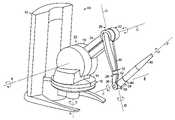
- FIG. 1is a schematic perspective view of a six degree of freedom force reflecting haptic interface 10 in accordance with one embodiment of the present invention.
- the interface 10includes a housing 12 defining a reference ground, six joints or articulations, and six structural elements.
- a first powered tracked rotary element 14is supported by the housing 12 to define a first articulation 16 with an axis “A” having a substantially vertical orientation.
- a second powered tracked rotary element 18is mounted thereon to define a second articulation 20 with an axis “B” having a substantially perpendicular orientation relative to the first axis, A.
- a third powered tracked rotary element 22is mounted on a generally outwardly radially disposed extension 24 of the second element 18 to define a third articulation 26 having an axis “C” which is substantially parallel to the second axis, B.
- a fourth free rotary element 28is mounted on a generally outwardly radially disposed extension 30 of the third element 22 to define a fourth articulation 32 having an axis “D” which is substantially perpendicular to the third axis, C.
- a fifth free rotary element 34is mounted on a generally outwardly radially disposed extension 36 of the fourth element 28 to define a fifth articulation 38 having an axis “E” which is substantially perpendicular to the fourth axis, D.
- a sixth free rotary user connection element 40in the form of a stylus configured to be grasped by a user is mounted on a generally outwardly radially disposed extension 42 of the fifth element 34 to define a sixth articulation 44 having an axis “F” which is substantially perpendicular to the fifth axis, E.
- the interface 10employs three dedicated actuators fitted with capstans and corresponding cables to power rotary axes A-C.
- Cable drivesprovide good force transmission characteristics with low weight; however, backlash can be a problem, especially in high precision, high resolution haptic interfaces. Backlash or play in a rotary mechanical transmission, such as those employed in the interface 10 , is most evident when direction of rotation is reversed.
- One method of reducing backlashis to provide a manual adjustment feature to adjust the position of one or both of the cable ends relative to ground so that slack in the cable can be reduced. Further, the cable can be preloaded in tension so that there is minimal slippage between the cable and the actuator capstan as the capstan rotates.
- FIG. 2Ais a schematic view of an automatic cable tensioning device 46 which overcomes many of the limitations of known cable drives and is useful in the powered axes of the haptic interface 10 in accordance with one embodiment of the present invention.
- the tensioning device 46automatically loads the cable to a predetermined tension and maintains that level of tension over time, even in the event of cable stretching and component wear.
- the tensioning device 46includes a cable 48 fixed at proximal and distal ends directly or indirectly to a ground surface, shown generally at 50 a , 50 b .
- a non-rotating clutch post 52also fixed to ground, is located along the cable path.
- a spring 54is disposed along the cable path between the clutch post 52 and ground 50 b .
- an actuator capstan 56is provided along the cable path between the clutch post 52 and ground 50 a on the side opposite the spring 54 .
- the cable 48extends from ground 50 a , circumscribes both the actuator capstan 56 and the clutch post 52 at least once each, and is connected to the spring 54 , which is in tension and connected to ground 50 b.
- a non-rotating postsuch as clutch post 52
- the amplification factoris a function of post diameter, wrap angle of the cable around the post, and the coefficient of friction between the cable and the post. Accordingly, for a given spring tension, as wrap angle and/or friction increases, a larger downstream cable forces can be offset or resisted.
- the tension induced in the cable 48 by the spring 54causes the cable to be pulled to the right, eliminating any slack or looseness in the cable 48 , cable tension being a function of the spring constant, k, and the linear displacement, x, of the spring ends from a rest state.
- tensionis applied to the portion of the cable 48 between the capstan 56 and ground 50 a and the capstan 56 moves to the left relative to ground 50 a .
- Any looseness or slack in the cable to the right of the capstan 56is automatically taken up by the spring 54 , the cable 48 sliding around the clutch post 52 whenever the spring force overcomes the frictional drag of the cable 48 around the clutch post 52 .
- the tensioning device 46automatically self-adjusts and maintains cable tension at a predetermined magnitude, taking up any slack when the capstan 56 rotates in a first direction and locking when the capstan 56 rotates in a second direction.
- FIGS. 2B-2Edepict several applications of the principles of the tensioning device 46 in the powered axes of the haptic interface 10 .
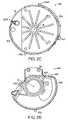
- FIG. 2Bis a schematic plan view of an automatic cable tensioning device 146 employed in the first articulation 16 of the haptic interface 10 .
- Depictedis a generally circular hub portion of the first element 14 .
- a cable 148is fixed to the element 14 at a first ground location 150 a and circumscribes the element 14 in a clockwise direction.
- the cable 148wraps an actuator capstan 156 disposed substantially tangentially to the circumference before wrapping several times around a clutch post 152 . Thereafter, the cable is attached to a spring 154 in tension which is grounded to the element 14 at 150 b .
- the actuator(not depicted) is fixed in the housing 12 of the interface 10 , as the actuator rotates the capstan 156 , the first element 14 is caused to rotate about first axis A.
- tabs, slots, and other guide featuresare provided in the element 14 to facilitate routing and retention of the cable 148 in the proper location and orientation throughout the range of motion of the element 14 .
- FIG. 2Cis a schematic plan view of an automatic cable tensioning device 246 employed in the second articulation 20 of the haptic interface 10 .
- Depictedis a generally circular hub portion of the second element 18 .
- a cable 248is fixed to the element 18 at a first ground location 250 a and circumscribes the element 18 in a counterclockwise direction.
- the cable 248wraps an actuator capstan 256 disposed substantially tangentially to the circumference before wrapping several times around a clutch post 252 . Thereafter, the cable is attached to a spring 254 in tension which is grounded to the element 18 at 250 b . Since the actuator (not depicted) is fixed to the first element 14 , as the actuator rotates the capstan 256 , the second element 18 is caused to rotate about the second axis B.
- FIG. 2Dis a schematic plan view of a first automatic cable tensioning device 346 employed to drive a transfer drive element 58 of the third articulation 26 of the haptic interface 10 .
- the cable drive transmission for the third articulation 26spans a distance from the hub of the second element 18 , along the extension 24 thereof, to a hub of the third element 22 .
- the actuator for the third articulation 26is disposed remotely, proximate the actuator for the second articulation 20 in the hub thereof, to minimize the size and the weight of the cantilevered third articulation 26 .
- the second articulation hubis configured with two rotatable components nested on a common axis, namely the second axis, B, as will be discussed in greater detail hereinbelow.
- the transfer drive element 58is journaled for rotation about the second axis B.
- a cable 348is fixed to the element 58 at a ground location 350 and circumscribes the element 58 in a clockwise direction.
- the cable 348wraps an actuator capstan 356 disposed substantially tangentially to the circumference before wrapping several times around a clutch post 352 .
- the cableis attached to a spring 354 in tension which is grounded to the element 58 at 250 . Since the actuator (not depicted) is fixed to the first element 14 , as the actuator rotates the capstan 356 , the transfer drive element 58 is caused to rotate about second axis B.
- a reverse side of the transfer drive element 58is depicted in FIG. 2E and employs a second automatic cable tensioning device 446 for transferring the rotation of the drive element located in the hub of the second element 18 to the third articulation 26 .
- a first rigid transfer drive rod 60 grounded to the third element 22is crimped or otherwise attached to a tungsten or stainless steel cable 448 proximate the drive element 58 .
- the cable 448circumscribes a central hub of the drive element 58 in a clockwise direction.
- the cable 448wraps several times around a clutch post 452 before being attached to a spring 454 in tension which is grounded to the element 58 at 450 .
- FIG. 3Ais a schematic cross-sectional view of a grounded actuator capstan 456 for use in the cable drives of the haptic interface 10 in accordance with an embodiment of the present invention.
- the grounded capstan 456may be used with conventional cable drives or advantageously with the automatic cable tensioning device 46 .
- the generally cylindrical capstan 456forms a centrally disposed bore 62 sized to receive an actuator shaft 64 .
- the capstan 456may be secured to the shaft 64 by bonding, mechanical fastening, or any other suitable method.
- a keyway, spline, or other anti-rotation featuremay also IS be provided, if desired.
- a generally centrally radially disposed aperture 66is provided in the capstan 456 , the aperture 66 sized to permit passage therethrough of a double portion of a drive cable 558 .
- the shaftmay be D-shaped or have a flat or groove formed therein as shown generally at 68 .
- knottingrefers to the process of forming a bulge in a length of cable. This may be achieved by tying the two lengths together or by using a device which crimps the two lengths together in a bead. In the former method, the knot is formed by the cables themselves and in the latter case, the knot is effectively the bead which holds the two cables together. Alternatively, a single length of cable can be doubled over, passed through the aperture 66 , and knotted. In either case, the knotting 70 is provided to prevent the cable 558 from being pulled back through the aperture 66 .
- An adhesivemay be applied to the knotting 70 to prevent unraveling, if desired.
- the aperture 66is aligned with the shaft flat 68 , generally as depicted, to positively capture the knotted portion 70 without severing the cable 558 .
- the individual free ends of the cablemay be wrapped in opposite directions around the capstan 456 , as depicted in FIG. 3B , and routed as desired. For example, one free end may be attached to ground and the other wrapped around a clutch post before being attached to a spring which is in turn attached to ground.
- the capstan 456may be a uniform cylinder, in one embodiment, the capstan 456 includes a helical channel 72 formed along an exterior surface thereof.
- the cable aperture 66is aligned with a valley of the channel 72 so that both portions of the cable 558 exiting the aperture 66 can be smoothly wrapped around the capstan 456 .
- the opening of the aperture 66may include a generous radius to blend the aperture 66 with the helical channel 72 without sharp edges which could cut through the cable 558 or otherwise reduce the life thereof.
- the helical channel 72nests and routes the cable 558 , preventing overlapping or tangling of the cable 558 on the capstan 456 .
- FIG. 5AAn enlarged portion of a capstan 456 with a helical channel 72 is depicted in FIG. 5A .
- the capstan 456has a trough diameter T D and a crest diameter C D measured from a centerline of the capstan 456 , and a trough radius T R .
- T Dequals 0.175 inches
- C Dequals 0.189 inches
- T Requals 0.010 inches; however, T D , C D , and T R may be sized, as necessary, depending on the geometry of the cable.
- the helical channel 72 shownis a right hand thread with a 0.0227 pitch (i.e., 44 threads per inch); however, the capstan 456 may have a left hand thread and the thread pitch may be varied as necessary.
- the radial height of the channel 72 between the trough to the cresti.e., C D -T D ) is about equal to the radius of the cable 558 , and the trough radial contour 162 is up to about 50 percent greater than the radius of the cable 558 .
- the helical channel 72has a uniform radius (T R ) for nesting and routing the cable 558 .
- the channel 72could be V-shaped; however, the U-shape of a channel 72 with a uniform radius is believed to support the cable better and enhance useful cable life.
- the centerline 158 of the cable 558should be approximately aligned with the crest 160 of the channel 72 .
- the crest to crest distance (X)should be greater than the cable 558 diameter (Y) by up to about 50 percent.
- a channel 72 with a trough radius of 0.010 inches nesting a cable with a diameter (Y) of 0.014 inchesyields an X dimension 42 percent greater than the cable diameter (Y). Accordingly, at increased loads, the cable may deform slightly and increase surface contact between the cable and the channel. The increased surface contact may obviate the need for a grounded capstan, in which case, the aperture 66 would not be required.
- trough radius T Ris no more than about 5% to 10% greater than the radius of the cable.
- a groovemay be formed in the capstan bore 62 .
- a window or other cutoutmay be provided in the capstan 456 longitudinally spaced from the aperture 66 to provide space for the knot.
- Creepas opposed to elastic stretching, is the relatively slow, permanent plastic deformation of the cable which results from continued exposure to elevated levels of stress. For many materials, creep is exacerbated at increased temperatures. A cable with poor creep strength characteristics will permanently stretch and loosen over time, absent manual or automatic tension compensation.
- the polymer composition cables which can be used in the first and second axis drives and a portion of the third axis transfer drivemay be a fused blend of a high modulus polyethylene (HMPE) material and a liquid crystal aromatic polyester-polyarylate (LCAP) material which, in combination, has been shown to exhibit low creep, high strength, and long life.
- HMPEhigh modulus polyethylene
- LCAPliquid crystal aromatic polyester-polyarylate
- LCAP materialin similar forms, such as that manufactured by Hoechst Celanese, a division of Hoechst AG located in the Netherlands, and sold under the mark VectranTM, exhibits low creep, but is relatively brittle and prematurely frays after repeated cycling, making a cable manufactured solely from this material generally unsuitable for use in the cable drives discussed hereinabove.
- a polymer composition cable suitable for use in the haptic interface cable drivescan be manufactured by twisting or braiding together filaments, fibers, or yarns of HMPE and LCAP and subjecting the composite cable to an elevated temperature in the range of the respective melting points of the two materials for a period of time to at least partially fuse the two materials together.
- the heated composite cablemay also be drawn under tension while at the elevated temperature to more intimately consolidate the two component materials and improve the mechanical properties of the cable once cooled.
- the polymer composite cablemay have a composition of between about 20 percent to about 80 percent HMPE, balance LCAP. In a preferred embodiment, the polymer composite cable may have a composition of between about 30 percent to 70 percent HMPE, balance LCAP. In a more preferred embodiment, the polymer composite cable may have a composition between about 40 percent to 60 percent HMPE, balance LCAP.
- the aforementioned compositionsrelate solely to the relative amounts of HMPE and LCAP.
- Other constituentssuch as coloring agents, fillers, and coatings may be employed to color the resultant cable, provide magnetic or electrical properties, increase wear life, improve performance at elevated temperatures, or enhance fusing during manufacture of the cable.
- the clutch posts 152 , 252 , and 352 adapted to be used with the polymer composition cableare made of 6061 T-6 aluminum and have an outer diameter of about 3/16 inches.
- the aluminum postsare tubular, being permanently bonded to posts molded in the respective elements manufactured, for example, from carbon filled polycarbonate.
- the clutch post 452 wrapped by the stranded stainless steel cableis larger, having an outer diameter of about 0.22 inches due to differences in flexibility of the cable and coefficient of friction between the cable and the clutch post 452 relative to the polymer cable drives.
- Cable tension in each driveis on the order of about 10 pounds force.
- the polymer composition cablehas a nominal diameter of about 0.014 inches with a breaking strength of between about 20 and 30 pounds force, although other sizes with different strengths can be used depending on the application.
- the cablesmay be wrapped around respective clutch posts typically between about 1.5 to 4 times.
- Automatic tensioning spring forcesare on the order of about 1 to 4 pounds force.
- the number of wraps and spring forcecan be selected as desired, depending on the anticipated maximum cable tension to be encountered during operation of the actuator, the diameter of the clutch post, and the coefficient of friction between the cable and the clutch post, in accordance with conventionally known mathematical relationships. Additionally, other materials may be used for the clutch posts.
- tubular aluminum postsmay be eliminated altogether, the molded post in the element being used as the clutch post at the same or a different diameter.
- the hardness and surface finish of the clutch postmay also affect performance of the automatic tensioning device due to wear and resultant changes in the effective coefficient of friction.
- the radius of the capstanis a fundamental limit on the reduction ratio of the transmission. Accordingly, the smaller the capstan, the more efficient and less costly the cable drive transmission.
- the tungsten cablehas a nominal braided diameter of 0.015 inches, swaged to a final diameter of about 0.014 inches.
- Cable constructionis 8 ⁇ 19 class, utilizing a 7 ⁇ 7 core wrapped by eight 1 ⁇ 19 filament strands.
- cable or wire ropeas it is sometimes known, is designated by two figures, the first indicating the number of strands and the second, the number of wires or filaments per strand.
- each filamentis nominal 0.0008 inch diameter tungsten material, such as that used in the manufacture of light bulb filaments. This is a much smaller nominal diameter than that of stainless steel filaments which can usually only be drawn as fine as about 0.003 inches in diameter.
- This particular tungsten cablehas a nominal breaking strength of about 37 pounds; however, higher breaking strengths have been measured, depending on how the load is applied to the cable. For example, a breaking strength of about 42.5 pounds has been measured by grabbing the cable, and a breaking strength of about 47 pounds measured using a capstan.
- the cableis available from Alan Baird Industries, located in Hohokus, N.J. as manufacturer's part number ALA8908LD1.
- Capstans used with a tungsten cablemay have a minimum diameter less than 0.25 inches at the base of the groove. In one example, the capstan diameter is 0.175 inches at the base of the groove.
- the above referenced 0.014 inch cable used with a 0.175 inch capstanyields a 12.5:1 ratio. Accordingly, whereas a stainless steel cable shows signs of fraying and wear after some 750,000 cycles, a tungsten cable of the same nominal diameter subjected to the same loading and test conditions exhibits no visible signs of wear after 5,500,000 cycles. Lubrication applied to a cable will decrease fraying and wear of the cable. In one embodiment using tungsten cable, lubrication is not absolutely required, as the tungsten cable contains residual carbon resulting from hydrocarbon lubricant burned during the swaging process.
- the tungsten cablecan also offer certain advantages over the polymer composition cable discussed hereinabove.
- the tungsten cablehas a nominal breaking strength of 37 pounds, over twice the 17 pound breaking strength of the polymer cable.
- the cableis relatively stiff in the longitudinal direction. Accordingly, there is near zero hysteresis during use, due in part to the swaging process which imparts a residual stress in the cable.
- the tungsten cablealso is contemplated to exhibit negligible creep over the useful life of the cable, based on observations during the aforementioned cyclic testing.
- the tungsten cablealso grips clutch posts and capstans securely, due to the surface characteristics of the cable. Accordingly, the cable may be used with or without the grounded capstans discussed hereinabove with respect to FIGS. 3A and 3B , as well as with or without metal sleeves on the clutch posts. Also, the cables can be manufactured to accurate lengths, for example within a tolerance of about plus or minus 0.03 inches for a 15 inch cable, for example, by crimping the ends to form loops for attachment to the transmission elements. The tungsten cable is also quite stable at elevated temperatures of 200° F. or higher, which can occur in haptic interfaces.
- a tungsten cablecan be used advantageously in a haptic interface transmission drive to achieve the benefits of each of standard stainless steel cables and the above described polymer composition cables, without the inherent shortcomings of each.
- One embodimentuses tungsten cables in the first and second axis drives and a portion of the third axis transfer drive.
- FIG. 4Adepicted is a schematic perspective view of the transfer drive, shown generally at 74 , for powering the third articulation 26 of the haptic interface 10 in accordance with one embodiment of the present invention.
- FIG. 4Bis a schematic perspective view of the actuator end of the transfer drive 74 depicted in FIG. 4A .
- Several covers of the haptic interface elementshave been removed to expose the components.
- second axis actuator 76 and third axis actuator 78Mounted on the first element 14 are second axis actuator 76 and third axis actuator 78 .
- the first axis actuatoris disposed in the housing 12 and cannot be seen in this view; however, the capstan 156 thereof is partially visible.
- the transfer drive element 58rotates about second axis B, converting rotary motion to linear motion of first and second transfer drive rods 60 , 80 disposed along the radial extension 24 of the second element 18 .
- the drive rods 60 , 80terminate in looped braided tungsten or stranded stainless steel cable ends which are hooked onto a raised ground tab of the third element 22 .
- the second transfer drive rod 80is directly grounded through looped cable ends to each of the drive element 58 and the third element 22 ; whereas, the first drive rod 60 is directly grounded through a looped cable end to the third element 22 and indirectly grounded to the drive element 58 through the clutch post 452 and spring 454 depicted in FIG. 2E .
- the drive rods 60 , 80minimize cable lengths and therefore enhance the stiffness and rigidity of the transfer drive 74 .
- the cablesare used solely at the grounding points, with one cable end of the first drive rod 60 being routed through the automatic cable tensioning device 446 depicted in FIG. 2E to substantially eliminate backlash in the third axis drive.
- the tension achieved with the automatic cable tensioning devicealso provides added stiffness and rigidity in the drive system.
- a counterweight 164rigidly attached to member 18 can be used to assist the spring 82 in counterbalancing those elements which rotate about the second axis B.
- a counterweight 166rigidly attached to transfer drive element 58 moves with element 58 in a manner that counterbalances the motion of remotely located members such as the third element 22 , fourth element 28 , fifth element 34 , and stylus 40 as they move about axis C.
- FIG. 4Bdepicts the substantial structural ribbing of the interior portion of the second element 18 , especially the extension 24 thereof.
- the haptic interface 10is designed such than the elements themselves provide the structural integrity or skeleton of the interface 10 , rather that having mechanical frames and the like merely encased in cosmetic covers. Accordingly, the skeleton of the interface may be considered as an exoskeleton, with the cable drives, articulation bearings, and other transmission components attached thereto.
- Desirable characteristics for the base portion, or housing 12 , of the haptic interfacealso include low cost, high strength, and high stiffness; however, because the base structure may also serve as a heat sink for the internal electronics, it is desirable that the base structure be significantly thermally conductive.
- the haptic interfaceshould have enough weight to prevent movement during the application of forces to a user.
- a plaster cast or die cast zinc materialmay be used in the construction of the housing 12 .
- suitable materialsinclude cast iron, bronze, and aluminum.
- each of the actuatorsis fitted with an optical encoder 84 having an encoder disk 86 and an emitter/detector pair 88 as depicted in FIG. 5 .
- the encoder disk 86is mounted on the actuator shaft 64 using a collar 92 disposed proximate the capstan 456 . Accordingly, the overall volume required for the actuator 90 in the haptic interface 10 can be minimized for a given size actuator 90 .
- the emitter/detector pair 88straddles an edge of the disk 86 , outputting pulses as the shaft 64 and disk 86 rotate so that the angular orientation of the powered articulation can be determined.
- the haptic interface 10may include automatic work volume calibration components for use in combination with computer software such that the haptic system, as a whole, has the capability to initialize position of the haptic interface 10 when the system is energized and geometrically center the user reference point in both the workspace volume and virtual or remote environment.
- each of the actuators for axes A-Cincludes an encoder 84 for tracking the angular orientation of the first element 14 , second element 18 , and third element 22 . Since the relative encoders, however, provide indications of relative angular rotation, an absolute reference is needed to define a “home” position for each element. As best seen in FIG. 4B , the second element 18 includes three axially disposed flags 94 a - c forming gaps 95 a - c having different circumferential lengths.
- the flags 94 a - c and gaps 95 a - csequentially pass through an emitter/detector pair 96 . Based on the number of encoder pulses counted during passage of any given flag 94 or gap 95 through the emitter/detector pair 96 , the specific flag 94 or gap 95 and angular orientation of the second element relative to the home position can be determined.
- the first element 14 and second element 18each have three flags and the third element 22 solely one, due to space constraints. Although one flag or gap is sufficient, a plurality of flags and gaps with different lengths located at several circumferential locations permits determining the absolute angular orientation of the element more readily, with lesser manual or automatic angular rotation of the element being required.
- the angular location of each of the fourth element 28 , fifth element 34 , and sixth user connection element or stylus 40 about respective axes D-Fmay be tracked using respective potentiometers.
- a userWhen the haptic interface system is energized, a user can be directed to manually move the stylus 40 and connected elements through respective ranges of motion within the work volume of the haptic interface 10 to geometrically calibrate the workspace.
- the three actuatorsmay be used to automatically drive the powered axes through their range of motion to achieve a similar result.
- the systemmay adjust itself through monitoring during normal use to compensate, for example, for system wear or cable stretch.
- other devicessuch as a microswitch or proximity switch could be used.
- potentiometers or absolute encodersmay be employed as a substitute for, or in addition to, the relative encoders for measuring the absolute position of the rotary axes of the device.
- the user connection element or stylus 40 of the haptic interface 10may include a detector 100 for detecting the presence of a user, according to one embodiment of the invention.
- FIG. 6depicts a cross-sectional view of one embodiment of the stylus 40 which includes the presence detector 100 .
- the presence detector 100determines whether a portion of a user's body is physically contacting the stylus 40 .
- the stylusmay also include a mechanical push-button switch 98 actuated by squeezing the stylus 40 proximate thereto for other control purposes.
- the presence detector 100includes an electrically conductive portion 102 , circuitry 104 , and a connector 106 which electrically couples the conductive portion 102 to the circuitry 104 .
- the conductive portion 102 shown in FIG. 6extends along an axial and circumferential portion of an external surface 108 of the stylus 40 which is typically contacted by a user when grasping the stylus 40 . In other embodiments, the conductive portion 102 may extend along shorter or longer portions of the surface 108 in both axial and circumferential directions. In yet another embodiment, the conductive portion 102 may envelop substantially the entire external surface 108 of the stylus 40 .
- the conductive portion 102may be composed of any material which conducts electricity. In one embodiment, the conductive portion 102 is composed of conductive rubber.
- the circuitry 104is electrically coupled to the conductive portion 102 by the connector 106 .
- the connector 106 shown in FIG. 6is a spring contact which presses against an interior surface of the conductive portion 102 .
- the circuitry 104is arranged on a printed circuit card which is in electrical communication with a main circuit board of the haptic interface 10 disposed, for example, in the housing 12 .
- the circuitry 104detects the capacitance of the user's body relative to electrical ground.
- the circuitry 104includes an oscillator 110 , a signal divider 112 , a variable delay 114 , a phase detector 116 , a connector 118 , the push-button switch 98 , and light emitting diodes 122 .
- the oscillator 110generates a signal which is input to the signal divider 112 .
- a capacitor 124 and a resistor 126 of the signal divider 112generate two pulses.
- a first pulse 128is received by a clock input terminal 120 of a flip-flop 130 of the phase detector 116 and a second pulse 131 is received by the variable delay 114 .
- the variable delay 114has an input terminal 132 which is electrically coupled to the conductive portion 108 by the connector 106 .
- the variable delay 114delays the second pulse 131 from reaching the phase detector 116 . If the user is contacting the conductive portion 108 , the capacitance of the user changes the capacitance of the variable delay 114 and delays the second pulse 131 .
- a Schmitt trigger 134operates to square up the second pulse 131 into a square wave pulse 136 which is received by a D input terminal 135 of the flip-flop 130 . The amount that the pulse 131 is delayed depends on the capacitance of the user.
- the input to the D terminal 135 of the flip-flop 130will be high or asserted if the user is not contacting the conductive portion 108 . If the user is contacting the conductive portion 108 , the pulse 136 is shifted to the right and the input to the D terminal 135 of the flip-flop 130 will be low or unasserted.
- the flip-flop 135outputs a signal at a Q terminal 136 thereof which indicates the presence or absence of a user. This signal is read by the system computer which may enable or disable the haptic interface 10 or take other actions based on this signal. In one embodiment, the haptic interface 10 upon detecting the absence of the user will actively maintain its last orientation so that the user may later conveniently re-grasp the device at the same location.
- the variable delay 114includes a surge protector 140 .
- the surge protector 140protects the circuitry of the variable delay 114 from surges of electricity, such as sparks of static electricity which may come into contact with the conductive portion 108 .
- Velocity limitsmay be provided for each of the powered axes to safely limit the speed of axes A-C in the event of a system programming error or system malfunction.
- the velocity limitsmay be implemented using computer hardware, for example, by providing for maximum actuator rotational speed limits for each of the axes in an integrated circuit or otherwise. These maximum actuator speeds are typically different, due to the different geometric and mechanical configuration of each powered axis.
- the systemmay dynamically brake the actuators electrically to slow the errant axis or otherwise disable the axis.
- the actuatorsare DC motors
- the actuatorscan be effectively braked by shunting the inputs to the motors.
- Velocity limitsmay be implemented in system software, either redundantly in addition to the hardware limits, or alternatively. If used in a redundant system, these software limits may be implemented advantageously at levels slightly below those of the hardware limits so that they are triggered first.
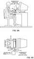
- FIG. 8Ais a schematic side view of an ergonomic representation of a user employing the haptic interface 10 in combination with a wrist rest 142 and other system components in a desktop environment.
- FIG. 8Bis a schematic top view of the ergonomic representation depicted in FIG. 8A .
- the forearm and wristmay be maintained in a natural, neutral orientation for comfortably grasping and manipulating the stylus 40 .
- the height and orientation of the wrist rest 142could be made adjustable.
- the wrist rest 142is connected to the haptic interface 10 , although a separate stand alone wrist rest with appropriate height and orientation could be used.
- the haptic interfaceis disposed advantageously proximate a system keyboard within easy reach of a user, typically inboard of a mouse pad area.
- FIGS. 9A-9Dare schematic top, side, end section, and partial section views of a contact pad 144 for use in the wrist rest 142 for use in combination with the haptic interface in accordance with an embodiment of the present invention.
- the contact pad 144may include a structural tray 145 for supporting a gel and/or foam material optionally encased, wholly or partially, in a natural or synthetic fabric, skin, or other covering 147 .
- a soft silicone gelmay be used.
- the surface of the contact pad adapted to support the user's wristmay be substantially planar, concave, or convex in any direction.
- the dimensions shown in FIGS. 8 A- 8 B and 9 A- 9 Dare merely exemplary in nature. Actual dimensions may be varied, as necessary to accommodate a particular haptic interface configurations, orientation, and work volume.
Landscapes
- Engineering & Computer Science (AREA)
- General Engineering & Computer Science (AREA)
- Theoretical Computer Science (AREA)
- Human Computer Interaction (AREA)
- Physics & Mathematics (AREA)
- General Physics & Mathematics (AREA)
- User Interface Of Digital Computer (AREA)
Abstract
Description
Claims (9)
Priority Applications (1)
| Application Number | Priority Date | Filing Date | Title |
|---|---|---|---|
| US11/231,347US7714836B2 (en) | 1998-07-17 | 2005-09-20 | Force reflecting haptic interface |
Applications Claiming Priority (3)
| Application Number | Priority Date | Filing Date | Title |
|---|---|---|---|
| US9330098P | 1998-07-17 | 1998-07-17 | |
| US09/356,289US6985133B1 (en) | 1998-07-17 | 1999-07-16 | Force reflecting haptic interface |
| US11/231,347US7714836B2 (en) | 1998-07-17 | 2005-09-20 | Force reflecting haptic interface |
Related Parent Applications (1)
| Application Number | Title | Priority Date | Filing Date |
|---|---|---|---|
| US09/356,289ContinuationUS6985133B1 (en) | 1998-07-17 | 1999-07-16 | Force reflecting haptic interface |
Publications (2)
| Publication Number | Publication Date |
|---|---|
| US20060033707A1 US20060033707A1 (en) | 2006-02-16 |
| US7714836B2true US7714836B2 (en) | 2010-05-11 |
Family
ID=35517831
Family Applications (2)
| Application Number | Title | Priority Date | Filing Date |
|---|---|---|---|
| US09/356,289Expired - LifetimeUS6985133B1 (en) | 1998-07-17 | 1999-07-16 | Force reflecting haptic interface |
| US11/231,347Expired - LifetimeUS7714836B2 (en) | 1998-07-17 | 2005-09-20 | Force reflecting haptic interface |
Family Applications Before (1)
| Application Number | Title | Priority Date | Filing Date |
|---|---|---|---|
| US09/356,289Expired - LifetimeUS6985133B1 (en) | 1998-07-17 | 1999-07-16 | Force reflecting haptic interface |
Country Status (1)
| Country | Link |
|---|---|
| US (2) | US6985133B1 (en) |
Cited By (13)
| Publication number | Priority date | Publication date | Assignee | Title |
|---|---|---|---|---|
| USD717300S1 (en)* | 2014-03-28 | 2014-11-11 | 3D Systems, Inc. | Computer interface |
| US9030411B2 (en) | 2004-06-29 | 2015-05-12 | 3D Systems, Inc. | Apparatus and methods for haptic rendering using a haptic camera view |
| US9050527B2 (en) | 2012-08-23 | 2015-06-09 | Wms Gaming Inc. | Interactive tether using tension and feedback |
| US9119655B2 (en) | 2012-08-03 | 2015-09-01 | Stryker Corporation | Surgical manipulator capable of controlling a surgical instrument in multiple modes |
| US9226796B2 (en) | 2012-08-03 | 2016-01-05 | Stryker Corporation | Method for detecting a disturbance as an energy applicator of a surgical instrument traverses a cutting path |
| US9480534B2 (en) | 2012-08-03 | 2016-11-01 | Stryker Corporation | Navigation system and method for removing a volume of tissue from a patient |
| WO2017136710A2 (en) | 2016-02-05 | 2017-08-10 | Board Of Regents Of The University Of Texas System | Surgical apparatus |
| US20170265948A1 (en)* | 1999-04-07 | 2017-09-21 | Intuitive Surgical Operations, Inc. | Medical Robotic System with Dynamically Adjustable Slave Manipulator Characteristics |
| US9820818B2 (en) | 2012-08-03 | 2017-11-21 | Stryker Corporation | System and method for controlling a surgical manipulator based on implant parameters |
| US9921712B2 (en) | 2010-12-29 | 2018-03-20 | Mako Surgical Corp. | System and method for providing substantially stable control of a surgical tool |
| US10537815B2 (en)* | 2012-07-16 | 2020-01-21 | Shmuel Ur | System and method for social dancing |
| EP3799822A1 (en) | 2017-06-29 | 2021-04-07 | The Board of Regents of the University of Texas System | Surgical apparatus |
| US11202682B2 (en) | 2016-12-16 | 2021-12-21 | Mako Surgical Corp. | Techniques for modifying tool operation in a surgical robotic system based on comparing actual and commanded states of the tool relative to a surgical site |
Families Citing this family (63)
| Publication number | Priority date | Publication date | Assignee | Title |
|---|---|---|---|---|
| US5825308A (en) | 1996-11-26 | 1998-10-20 | Immersion Human Interface Corporation | Force feedback interface having isotonic and isometric functionality |
| US6028593A (en) | 1995-12-01 | 2000-02-22 | Immersion Corporation | Method and apparatus for providing simulated physical interactions within computer generated environments |
| US8508469B1 (en) | 1995-12-01 | 2013-08-13 | Immersion Corporation | Networked applications including haptic feedback |
| US7091948B2 (en)* | 1997-04-25 | 2006-08-15 | Immersion Corporation | Design of force sensations for haptic feedback computer interfaces |
| US6717573B1 (en) | 1998-06-23 | 2004-04-06 | Immersion Corporation | Low-cost haptic mouse implementations |
| US6184868B1 (en)* | 1998-09-17 | 2001-02-06 | Immersion Corp. | Haptic feedback control devices |
| US6697043B1 (en) | 1999-12-21 | 2004-02-24 | Immersion Corporation | Haptic interface device and actuator assembly providing linear haptic sensations |
| US7038667B1 (en)* | 1998-10-26 | 2006-05-02 | Immersion Corporation | Mechanisms for control knobs and other interface devices |
| US8996169B2 (en) | 2011-12-29 | 2015-03-31 | Mako Surgical Corp. | Neural monitor-based dynamic haptics |
| US7831292B2 (en)* | 2002-03-06 | 2010-11-09 | Mako Surgical Corp. | Guidance system and method for surgical procedures with improved feedback |
| TW200304608A (en)* | 2002-03-06 | 2003-10-01 | Z Kat Inc | System and method for using a haptic device in combination with a computer-assisted surgery system |
| US8010180B2 (en) | 2002-03-06 | 2011-08-30 | Mako Surgical Corp. | Haptic guidance system and method |
| US11202676B2 (en) | 2002-03-06 | 2021-12-21 | Mako Surgical Corp. | Neural monitor-based dynamic haptics |
| US20040040800A1 (en)* | 2002-07-31 | 2004-03-04 | George Anastas | System and method for providing passive haptic feedback |
| EP1638466B1 (en)* | 2003-06-18 | 2012-02-08 | Koninklijke Philips Electronics N.V. | Remotely held needle guide for ct fluoroscopy |
| US7411576B2 (en) | 2003-10-30 | 2008-08-12 | Sensable Technologies, Inc. | Force reflecting haptic interface |
| US8963958B2 (en)* | 2003-12-10 | 2015-02-24 | 3D Systems, Inc. | Apparatus and methods for adjusting a texture wrapped onto the surface of a virtual object |
| US7889209B2 (en)* | 2003-12-10 | 2011-02-15 | Sensable Technologies, Inc. | Apparatus and methods for wrapping texture onto the surface of a virtual object |
| US7626589B2 (en)* | 2003-12-10 | 2009-12-01 | Sensable Technologies, Inc. | Haptic graphical user interface for adjusting mapped texture |
| US8232969B2 (en)* | 2004-10-08 | 2012-07-31 | Immersion Corporation | Haptic feedback for button and scrolling action simulation in touch input devices |
| US20080200843A1 (en)* | 2005-08-09 | 2008-08-21 | Ohio Universtiy | Method and Apparatus for Measurement of Human Tissue Properties in Vivo |
| EP2021084A4 (en)* | 2006-05-11 | 2009-09-23 | Rehabtronics Inc | Method and apparatus for automated delivery of therapeutic exercises of the upper extremity |
| WO2007136769A2 (en) | 2006-05-19 | 2007-11-29 | Mako Surgical Corp. | Method and apparatus for controlling a haptic device |
| WO2007136739A2 (en)* | 2006-05-19 | 2007-11-29 | Mako Surgical Corp. | A method and apparatus for controlling a haptic device |
| WO2008058039A1 (en)* | 2006-11-06 | 2008-05-15 | University Of Florida Research Foundation, Inc. | Devices and methods for utilizing mechanical surgical devices in a virtual environment |
| US20080163118A1 (en)* | 2006-12-29 | 2008-07-03 | Jason Wolf | Representation of file relationships |
| WO2009094621A2 (en) | 2008-01-25 | 2009-07-30 | University Of Florida Research Foundation, Inc. | Devices and methods for implementing endoscopic surgical procedures and instruments within a virtual environment |
| ES2539521T3 (en)* | 2008-10-10 | 2015-07-01 | Fundacion Fatronik | Universal haptic drive system |
| US9158823B2 (en)* | 2008-10-15 | 2015-10-13 | At&T Intellectual Property I, L.P. | User interface monitoring in a multimedia content distribution network |
| US8770905B2 (en)* | 2008-11-04 | 2014-07-08 | King Fahd University Of Petroleum And Minerals | Anthropomorphic force-reflective master arm |
| US8241186B2 (en)* | 2010-05-07 | 2012-08-14 | Fitness Brands 2, Llc | Interactive exercise devices |
| KR20120028003A (en)* | 2010-09-14 | 2012-03-22 | 삼성전자주식회사 | Apparatus and method for 3-dimensional tactile display |
| US8849015B2 (en) | 2010-10-12 | 2014-09-30 | 3D Systems, Inc. | System and apparatus for haptically enabled three-dimensional scanning |
| KR101283327B1 (en) | 2011-04-14 | 2013-07-17 | 에이알비전 (주) | Haptic of haptic device for simulator of intravenous injection |
| US8956230B2 (en) | 2011-05-20 | 2015-02-17 | Sony Corporation | Haptic device for 3-D gaming |
| US8681130B2 (en) | 2011-05-20 | 2014-03-25 | Sony Corporation | Stylus based haptic peripheral for touch screen and tablet devices |
| US8749533B2 (en)* | 2011-05-20 | 2014-06-10 | Sony Corporation | Haptic device for carving and molding objects |
| US8773403B2 (en) | 2011-05-20 | 2014-07-08 | Sony Corporation | Haptic device for position detection |
| CN102320040B (en)* | 2011-08-11 | 2014-02-26 | 南昌大学 | A force-feedback interactive device that independently adjusts its self-weight balance |
| US8464603B2 (en) | 2011-09-19 | 2013-06-18 | Vivero One Research, Llc | Parallelogram based actuating device |
| US8931359B2 (en)* | 2011-09-19 | 2015-01-13 | Vivero One Research, Llc | Parallelogram based actuating device |
| US9802364B2 (en) | 2011-10-18 | 2017-10-31 | 3D Systems, Inc. | Systems and methods for construction of an instruction set for three-dimensional printing of a user-customizableimage of a three-dimensional structure |
| TWI463955B (en)* | 2012-02-20 | 2014-12-11 | Zong Jing Investment Inc | Eye makeup device |
| US9600072B2 (en)* | 2013-08-27 | 2017-03-21 | Prakash C R J Naidu | Wearable tactile display |
| US9314934B2 (en)* | 2014-02-27 | 2016-04-19 | Disney Enterprises, Inc. | Gravity-counterbalanced robot arm |
| JP6455050B2 (en)* | 2014-09-30 | 2019-01-23 | セイコーエプソン株式会社 | robot |
| US9946350B2 (en)* | 2014-12-01 | 2018-04-17 | Qatar University | Cutaneous haptic feedback system and methods of use |
| GB2538497B (en) | 2015-05-14 | 2020-10-28 | Cmr Surgical Ltd | Torque sensing in a surgical robotic wrist |
| CN104908042B (en)* | 2015-06-18 | 2017-02-01 | 华南理工大学 | Extensible-connection six-freedom-degree force feedback mechanical arm |
| US10101157B2 (en) | 2015-09-14 | 2018-10-16 | Eric Bharucha | Free-space force feedback system |
| US10973517B2 (en) | 2015-11-13 | 2021-04-13 | Intuitive Surgical Operations, Inc. | Stapler with composite cardan and screw drive |
| CN105443655A (en)* | 2015-12-10 | 2016-03-30 | 合肥工业大学 | Swing joint for realizing force balance and mechanism limit by using internal bending springs |
| WO2019023390A2 (en) | 2017-07-27 | 2019-01-31 | Intuitive Surgical Operations, Inc. | Medical device handle |
| CA3087094A1 (en) | 2017-12-28 | 2019-07-04 | Orbsurgical Ltd. | Microsurgery-specific haptic hand controller |
| CN108054865B (en)* | 2017-12-29 | 2019-08-30 | 徐伟明 | New energy automobile motor damping device |
| CN108054863B (en)* | 2017-12-29 | 2019-11-26 | 江苏远华轻化装备有限公司 | A kind of motor shock-absorbing device |
| CN108054864B (en)* | 2017-12-29 | 2019-10-22 | 泰州市海陵区骏马机械厂 | New energy automobile motor pedestal |
| US11857188B2 (en)* | 2018-12-21 | 2024-01-02 | Intuitive Surgical Operations, Inc. | Articulation assemblies for surgical instruments |
| CN113905675B (en) | 2019-05-31 | 2025-01-14 | 直观外科手术操作公司 | Staple cartridge for surgical instruments |
| US11871925B2 (en)* | 2020-07-28 | 2024-01-16 | Cilag Gmbh International | Surgical instruments with dual spherical articulation joint arrangements |
| US12402883B2 (en) | 2021-01-08 | 2025-09-02 | Intuitive Surgical Operations, Inc. | Surgical instrument with linear and purse string suture staples |
| US11971086B2 (en) | 2021-10-21 | 2024-04-30 | Vivero One Research, Llc | Cable tensioner |
| US20230169885A1 (en)* | 2021-12-01 | 2023-06-01 | Lafayette College | Virtual integrated machining simulator |
Citations (164)
| Publication number | Priority date | Publication date | Assignee | Title |
|---|---|---|---|---|
| US2475484A (en) | 1946-05-14 | 1949-07-05 | Nise Dwight Dee De | Method and means for imparting feel back to a manually-movable control element |
| US2906179A (en) | 1957-01-28 | 1959-09-29 | North American Aviation Inc | Vector gage |
| US3133649A (en) | 1961-06-30 | 1964-05-19 | Micro Technology Lab Inc | Motion reduction apparatus |
| US3139990A (en) | 1961-12-11 | 1964-07-07 | Central Res Lab Inc | Rugged-duty master-slave manipulator |
| US3168203A (en) | 1960-07-07 | 1965-02-02 | Gen Mills Inc | Manually operated hydraulic actuator control having feel-back |
| US3171549A (en) | 1961-07-21 | 1965-03-02 | Molins Machine Co Ltd | Mechanical handling apparatus |
| US3241687A (en) | 1965-03-10 | 1966-03-22 | Moline Organisation Ltd | Mechanical handling apparatus |
| US3263824A (en) | 1963-12-20 | 1966-08-02 | Northrop Corp | Servo controlled manipulator device |
| US3449008A (en) | 1967-06-08 | 1969-06-10 | Gen Dynamics Corp | Object handling system with remote manual control |
| US3531868A (en) | 1968-04-18 | 1970-10-06 | Ford Motor Co | Surface scanner for measuring the coordinates of points on a three-dimensional surface |
| US3561263A (en) | 1968-08-08 | 1971-02-09 | Task Corp | Force and moment dynamometer |
| US3618786A (en) | 1969-01-02 | 1971-11-09 | Gen Electric | Material-handling apparatus with end effector force resolver and feedback |
| US3620095A (en) | 1970-09-03 | 1971-11-16 | Nasa | Mechanically actuated triggered hand |
| US3629826A (en) | 1970-01-02 | 1971-12-21 | Ibm | Sectioning apparatus and method for character recognition systems |
| US3637092A (en) | 1970-04-30 | 1972-01-25 | Gen Electric | Material-handling apparatus |
| US3919691A (en) | 1971-05-26 | 1975-11-11 | Bell Telephone Labor Inc | Tactile man-machine communication system |
| US3948093A (en) | 1975-06-30 | 1976-04-06 | International Business Machines Corporation | Six degree of freedom force transducer for a manipulator system |
| US4062455A (en) | 1976-11-22 | 1977-12-13 | Flatau Carl R | Remote manipulator |
| US4150803A (en) | 1977-10-05 | 1979-04-24 | Fernandez Carlos P | Two axes controller |
| US4158797A (en)* | 1977-02-22 | 1979-06-19 | Haulamatic Corporation | Power hoist |
| US4221516A (en) | 1978-05-31 | 1980-09-09 | Central Research Laboratories, Inc. | Master-slave manipulator |
| US4229136A (en) | 1979-03-19 | 1980-10-21 | International Business Machines Corporation | Programmable air pressure counterbalance system for a manipulator |
| US4260319A (en) | 1978-07-28 | 1981-04-07 | Motoda Denshi Kogyo Kabushiki Kaisha | End position control robot |
| US4302138A (en) | 1978-02-01 | 1981-11-24 | Alain Zarudiansky | Remote handling devices |
| US4367532A (en) | 1979-10-12 | 1983-01-04 | Nordson Corporation | Manually programmable robot with power-assisted motion during programming |
| US4477973A (en) | 1982-07-14 | 1984-10-23 | Micro Control Systems, Inc. | Three dimensional graphics tablet |
| US4510574A (en) | 1981-09-09 | 1985-04-09 | Commissariat A L'energie Atomique | Servosystem between a master actuator and a slave actuator |
| US4521685A (en) | 1982-03-01 | 1985-06-04 | Lord Corporation | Tactile sensor for an industrial robot or the like |
| US4555960A (en) | 1983-03-23 | 1985-12-03 | Cae Electronics, Ltd. | Six degree of freedom hand controller |
| US4593470A (en) | 1982-07-14 | 1986-06-10 | Micro Control Systems, Inc. | Portable three dimensional graphics tablet |
| US4604016A (en) | 1983-08-03 | 1986-08-05 | Joyce Stephen A | Multi-dimensional force-torque hand controller having force feedback |
| US4632341A (en) | 1985-02-06 | 1986-12-30 | The United States Of America As Represented By The Secretary Of The Air Force | Stabilizing force feedback in bio-actuated control systems |
| US4648782A (en) | 1983-05-27 | 1987-03-10 | Kraft Brett W | Underwater manipulator system |
| US4655673A (en) | 1983-05-10 | 1987-04-07 | Graham S. Hawkes | Apparatus providing tactile feedback to operators of remotely controlled manipulators |
| US4661032A (en) | 1984-12-20 | 1987-04-28 | Agency Of Industrial Science & Technology, Ministry Of International Trade & Industry | Bilateral master-slave manipulator control device |
| US4676002A (en) | 1984-06-25 | 1987-06-30 | Slocum Alexander H | Mechanisms to determine position and orientation in space |
| US4680519A (en) | 1985-09-23 | 1987-07-14 | General Electric Co. | Recursive methods for world-to-joint transformation for a robot manipulator |
| US4703443A (en) | 1984-02-16 | 1987-10-27 | Kabushiki Kaisha Toshiba | Device for measuring the shape of a three-dimensional object |
| US4795296A (en) | 1986-11-17 | 1989-01-03 | California Institute Of Technology | Hand-held robot end effector controller having movement and force control |
| US4800721A (en) | 1987-02-13 | 1989-01-31 | Caterpillar Inc. | Force feedback lever |
| US4823634A (en) | 1987-11-03 | 1989-04-25 | Culver Craig F | Multifunction tactile manipulatable control |
| US4837734A (en) | 1986-02-26 | 1989-06-06 | Hitachi, Ltd. | Method and apparatus for master-slave manipulation supplemented by automatic control based on level of operator skill |
| US4853874A (en) | 1986-12-12 | 1989-08-01 | Hitachi, Ltd. | Master-slave manipulators with scaling |
| US4885692A (en)* | 1987-08-20 | 1989-12-05 | Honda Giken Kogyo K.K. | Cruise control system |
| US4887222A (en) | 1987-07-01 | 1989-12-12 | Hitachi, Ltd. | Method for controlling operation of industrial robot |
| US4888877A (en) | 1987-11-26 | 1989-12-26 | Carl-Zeiss-Stiftung, Heidenhein/Brenz | Articulating head for a coordinate-measuring instrument |
| US4891889A (en) | 1987-05-05 | 1990-01-09 | Garda Impianti S.R.L. | Apparatus for measure and/or check the position and orientation of characteristic spots or areas in structures, particularly in motor-vehicle bodies |
| US4893981A (en) | 1987-03-26 | 1990-01-16 | Kabushiki Kaisha Komatsu Seisakusho | Master/slave type manipulator |
| US4907970A (en) | 1988-03-30 | 1990-03-13 | Grumman Aerospace Corporation | Sidestick-type thrust control simulator |
| US4942545A (en) | 1988-06-06 | 1990-07-17 | Combustion Engineering, Inc. | Calibration of eddy current profilometry |
| US4973215A (en) | 1986-02-18 | 1990-11-27 | Robotics Research Corporation | Industrial robot with servo |
| US4982504A (en) | 1988-02-18 | 1991-01-08 | C.E. Johansson Ab | Method for determining positional errors and for compensating for such errors, and apparatus for carrying out the method |
| US4988981A (en) | 1987-03-17 | 1991-01-29 | Vpl Research, Inc. | Computer data entry and manipulation apparatus and method |
| US5004391A (en) | 1989-08-21 | 1991-04-02 | Rutgers University | Portable dextrous force feedback master for robot telemanipulation |
| US5007300A (en) | 1989-03-03 | 1991-04-16 | United Kingdom Atomic Energy Authority | Multi-axis hand controller |
| US5018922A (en) | 1987-03-26 | 1991-05-28 | Kabushiki Kaisha Komatsu Seisakusho | Master/slave type manipulator |
| US5019761A (en) | 1989-02-21 | 1991-05-28 | Kraft Brett W | Force feedback control for backhoe |
| US5024116A (en) | 1989-06-08 | 1991-06-18 | Kraft Brett W | Modular rotary actuator |
| US5038089A (en) | 1988-03-23 | 1991-08-06 | The United States Of America As Represented By The Administrator Of The National Aeronautics And Space Administration | Synchronized computational architecture for generalized bilateral control of robot arms |
| US5039254A (en) | 1989-12-14 | 1991-08-13 | Science Applications International Corporation | Passive grabbing apparatus having six degrees of freedom and single command control |
| US5040306A (en) | 1988-02-18 | 1991-08-20 | Renishaw Plc | Surface-sensing device |
| US5044956A (en) | 1989-01-12 | 1991-09-03 | Atari Games Corporation | Control device such as a steering wheel for video vehicle simulator with realistic feedback forces |
| US5050608A (en) | 1988-07-12 | 1991-09-24 | Medirand, Inc. | System for indicating a position to be operated in a patient's body |
| US5072361A (en) | 1990-02-01 | 1991-12-10 | Sarcos Group | Force-reflective teleoperation control system |
| US5088046A (en) | 1987-12-19 | 1992-02-11 | Renishaw Plc | Mounting for surface-sensing stylus and a method of using said mounting |
| US5103404A (en) | 1985-12-06 | 1992-04-07 | Tensor Development, Inc. | Feedback for a manipulator |
| US5105367A (en) | 1988-10-19 | 1992-04-14 | Hitachi, Ltd. | Master slave manipulator system |
| US5115178A (en) | 1989-09-27 | 1992-05-19 | Seiko Instruments Inc. | Gravity compensating mechanism for articulated type industrial robots |
| US5116180A (en) | 1988-07-18 | 1992-05-26 | Spar Aerospace Limited | Human-in-the-loop machine control loop |
| US5130632A (en) | 1989-12-06 | 1992-07-14 | Hitachi, Ltd. | Manipulator and control method therefor |
| US5143505A (en) | 1991-02-26 | 1992-09-01 | Rutgers University | Actuator system for providing force feedback to a dextrous master glove |
| US5142931A (en) | 1991-02-14 | 1992-09-01 | Honeywell Inc. | 3 degree of freedom hand controller |
| US5148377A (en) | 1986-12-10 | 1992-09-15 | Mcdonald Gregory J | Coordinate measuring system |
| US5155423A (en) | 1986-02-18 | 1992-10-13 | Robotics Research Corporation | Industrial robot with servo |
| US5184319A (en) | 1990-02-02 | 1993-02-02 | Kramer James F | Force feedback and textures simulating interface device |
| US5185561A (en) | 1991-07-23 | 1993-02-09 | Digital Equipment Corporation | Torque motor as a tactile feedback device in a computer system |
| US5189806A (en) | 1988-12-19 | 1993-03-02 | Renishaw Plc | Method of and apparatus for scanning the surface of a workpiece |
| US5193963A (en) | 1990-10-31 | 1993-03-16 | The United States Of America As Represented By The Administrator Of The National Aeronautics And Space Administration | Force reflecting hand controller |
| US5198736A (en) | 1990-11-15 | 1993-03-30 | Canon Kabushiki Kaisha | Orthogonal two-axis moving apparatus |
| US5220261A (en) | 1991-03-19 | 1993-06-15 | Bodenseewerk Geratetechnik Gmbh | Method of calibrating highly precise robots |
| US5220260A (en) | 1991-10-24 | 1993-06-15 | Lex Computer And Management Corporation | Actuator having electronically controllable tactile responsiveness |
| US5223776A (en) | 1990-12-31 | 1993-06-29 | Honeywell Inc. | Six-degree virtual pivot controller |
| US5230623A (en) | 1991-12-10 | 1993-07-27 | Radionics, Inc. | Operating pointer with interactive computergraphics |
| US5239246A (en) | 1992-07-08 | 1993-08-24 | The United States Of America As Represented By The Administrator Of The National Aeronautics And Space Administration | Force reflection with compliance control |
| US5239160A (en) | 1990-08-14 | 1993-08-24 | Tsubakimoto Chain Co. | Five-axis table for laser beam machine tool |
| US5251127A (en) | 1988-02-01 | 1993-10-05 | Faro Medical Technologies Inc. | Computer-aided surgery apparatus |
| US5255211A (en) | 1990-02-22 | 1993-10-19 | Redmond Productions, Inc. | Methods and apparatus for generating and processing synthetic and absolute real time environments |
| US5259120A (en) | 1991-07-27 | 1993-11-09 | Renishaw Transducer Systems Limited | Calibration and measurement device |
| US5264768A (en) | 1992-10-06 | 1993-11-23 | Honeywell, Inc. | Active hand controller feedback loop |
| US5320623A (en) | 1991-07-16 | 1994-06-14 | Orthofix S.R.1. | Clamping coupling for an external fixator |
| US5350033A (en) | 1993-04-26 | 1994-09-27 | Kraft Brett W | Robotic inspection vehicle |
| US5351692A (en) | 1993-06-09 | 1994-10-04 | Capistrano Labs Inc. | Laparoscopic ultrasonic probe |
| US5354162A (en) | 1991-02-26 | 1994-10-11 | Rutgers University | Actuator system for providing force feedback to portable master support |
| US5382885A (en) | 1993-08-09 | 1995-01-17 | The University Of British Columbia | Motion scaling tele-operating system with force feedback suitable for microsurgery |
| US5384460A (en) | 1993-11-03 | 1995-01-24 | Silitek Corporation | Encoder with a light emitting editing wheel |
| US5389865A (en) | 1992-12-02 | 1995-02-14 | Cybernet Systems Corporation | Method and system for providing a tactile virtual reality and manipulator defining an interface device therefor |
| US5396265A (en) | 1990-09-17 | 1995-03-07 | Massachusetts Institute Of Technology | Three-dimensional tactile computer input device |
| US5397323A (en) | 1992-10-30 | 1995-03-14 | International Business Machines Corporation | Remote center-of-motion robot for surgery |
| US5402582A (en) | 1993-02-23 | 1995-04-04 | Faro Technologies Inc. | Three dimensional coordinate measuring apparatus |
| US5429140A (en) | 1993-06-04 | 1995-07-04 | Greenleaf Medical Systems, Inc. | Integrated virtual reality rehabilitation system |
| US5436542A (en) | 1994-01-28 | 1995-07-25 | Surgix, Inc. | Telescopic camera mount with remotely controlled positioning |
| US5438529A (en) | 1994-01-26 | 1995-08-01 | Immersion Human Interface Corporation | Percussion input device for personal computer systems |
| US5445166A (en) | 1991-06-13 | 1995-08-29 | International Business Machines Corporation | System for advising a surgeon |
| US5482051A (en) | 1994-03-10 | 1996-01-09 | The University Of Akron | Electromyographic virtual reality system |
| US5489830A (en) | 1994-09-09 | 1996-02-06 | Mcdonnell Douglas Corporation | Control system with loadfeel and backdrive |
| US5515078A (en) | 1992-06-12 | 1996-05-07 | The Computer Museum, Inc. | Virtual-reality positional input and display system |
| US5516249A (en) | 1994-05-10 | 1996-05-14 | Technical Research Associates, Inc. | Exoskeleton with kinesthetic feedback and robotic control |
| EP0458343B1 (en) | 1990-05-25 | 1996-09-04 | BETTCHER INDUSTRIES, INC. (a Delaware Corporation) | Knittable yarn and safety apparel |
| US5555894A (en) | 1993-05-11 | 1996-09-17 | Matsushita Electric Industrial Co., Ltd. | Force sensation exhibiting device, data input device and data input equipment |
| US5576727A (en) | 1993-07-16 | 1996-11-19 | Immersion Human Interface Corporation | Electromechanical human-computer interface with force feedback |
| US5577417A (en) | 1993-11-08 | 1996-11-26 | Commissariat A L'energie Atomique | Tactile and/or kinesthetic manual information return control member |
| US5587937A (en) | 1993-10-01 | 1996-12-24 | Massachusetts Institute Of Technology | Force reflecting haptic interface |
| US5589854A (en) | 1995-06-22 | 1996-12-31 | Tsai; Ming-Chang | Touching feedback device |
| US5589828A (en) | 1992-03-05 | 1996-12-31 | Armstrong; Brad A. | 6 Degrees of freedom controller with capability of tactile feedback |
| USD377932S (en) | 1995-10-31 | 1997-02-11 | Immersion Human Interface Corporation | Mechanical digitizing arm used to input three dimensional data into a computer |
| US5623582A (en) | 1994-07-14 | 1997-04-22 | Immersion Human Interface Corporation | Computer interface or control input device for laparoscopic surgical instrument and other elongated mechanical objects |
| US5629594A (en) | 1992-12-02 | 1997-05-13 | Cybernet Systems Corporation | Force feedback system |
| US5642469A (en) | 1994-11-03 | 1997-06-24 | University Of Washington | Direct-drive manipulator for pen-based force display |
| US5691898A (en) | 1995-09-27 | 1997-11-25 | Immersion Human Interface Corp. | Safe and low cost computer peripherals with force feedback for consumer applications |
| US5694013A (en) | 1996-09-06 | 1997-12-02 | Ford Global Technologies, Inc. | Force feedback haptic interface for a three-dimensional CAD surface |
| US5721566A (en) | 1995-01-18 | 1998-02-24 | Immersion Human Interface Corp. | Method and apparatus for providing damping force feedback |
| US5724264A (en) | 1993-07-16 | 1998-03-03 | Immersion Human Interface Corp. | Method and apparatus for tracking the position and orientation of a stylus and for digitizing a 3-D object |
| US5731804A (en) | 1995-01-18 | 1998-03-24 | Immersion Human Interface Corp. | Method and apparatus for providing high bandwidth, low noise mechanical I/O for computer systems |
| US5734373A (en) | 1993-07-16 | 1998-03-31 | Immersion Human Interface Corporation | Method and apparatus for controlling force feedback interface systems utilizing a host computer |
| US5737505A (en) | 1995-01-11 | 1998-04-07 | Haptek, Inc. | Tactile interface apparatus for providing physical feedback to a user based on an interaction with a virtual environment |
| US5739811A (en) | 1993-07-16 | 1998-04-14 | Immersion Human Interface Corporation | Method and apparatus for controlling human-computer interface systems providing force feedback |
| US5742278A (en) | 1994-01-27 | 1998-04-21 | Microsoft Corporation | Force feedback joystick with digital signal processor controlled by host processor |
| US5754023A (en) | 1995-10-26 | 1998-05-19 | Cybernet Systems Corporation | Gyro-stabilized platforms for force-feedback applications |
| US5767839A (en) | 1995-01-18 | 1998-06-16 | Immersion Human Interface Corporation | Method and apparatus for providing passive force feedback to human-computer interface systems |
| US5769640A (en) | 1992-12-02 | 1998-06-23 | Cybernet Systems Corporation | Method and system for simulating medical procedures including virtual reality and control method and system for use therein |
| US5784542A (en) | 1995-09-07 | 1998-07-21 | California Institute Of Technology | Decoupled six degree-of-freedom teleoperated robot system |
| US5800178A (en) | 1995-03-29 | 1998-09-01 | Gillio; Robert G. | Virtual surgery input device |
| US5802353A (en) | 1996-06-12 | 1998-09-01 | General Electric Company | Haptic computer modeling system |
| US5800179A (en) | 1996-07-23 | 1998-09-01 | Medical Simulation Corporation | System for training persons to perform minimally invasive surgical procedures |
| US5805140A (en) | 1993-07-16 | 1998-09-08 | Immersion Corporation | High bandwidth force feedback interface using voice coils and flexures |
| US5803738A (en) | 1994-06-24 | 1998-09-08 | Cgsd Corporation | Apparatus for robotic force simulation |
| US5808665A (en) | 1992-01-21 | 1998-09-15 | Sri International | Endoscopic surgical instrument and method for use |
| US5807377A (en) | 1996-05-20 | 1998-09-15 | Intuitive Surgical, Inc. | Force-reflecting surgical instrument and positioning mechanism for performing minimally invasive surgery with enhanced dexterity and sensitivity |
| US5814038A (en) | 1995-06-07 | 1998-09-29 | Sri International | Surgical manipulator for a telerobotic system |
| US5816105A (en) | 1996-07-26 | 1998-10-06 | The United States Of America As Represented By The Administrator Of The National Aeronautics And Space Administration | Three degree of freedom parallel mechanical linkage |
| US5816823A (en) | 1994-08-18 | 1998-10-06 | Interval Research Corporation | Input device and method for interacting with motion pictures incorporating content-based haptic feedback |
| US5821920A (en) | 1994-07-14 | 1998-10-13 | Immersion Human Interface Corporation | Control input device for interfacing an elongated flexible object with a computer system |
| US5825308A (en) | 1996-11-26 | 1998-10-20 | Immersion Human Interface Corporation | Force feedback interface having isotonic and isometric functionality |
| US5825983A (en) | 1996-03-22 | 1998-10-20 | Korea Institute Of Science And Technology | Tactile feedback device for remote control robot using repulsive force of magnet |
| US5828197A (en) | 1996-10-25 | 1998-10-27 | Immersion Human Interface Corporation | Mechanical interface having multiple grounded actuators |
| US5828813A (en) | 1995-09-07 | 1998-10-27 | California Institute Of Technology | Six axis force feedback input device |
| US5857986A (en) | 1996-05-24 | 1999-01-12 | Moriyasu; Hiro | Interactive vibrator for multimedia |
| US5859934A (en) | 1994-05-05 | 1999-01-12 | Sri International | Method and apparatus for transforming coordinate systems in a telemanipulation system |
| US5889670A (en) | 1991-10-24 | 1999-03-30 | Immersion Corporation | Method and apparatus for tactilely responsive user interface |
| US5913727A (en) | 1995-06-02 | 1999-06-22 | Ahdoot; Ned | Interactive movement and contact simulation game |
| US5914705A (en) | 1996-02-09 | 1999-06-22 | Lucent Technologies Inc. | Apparatus and method for providing detent-like tactile feedback |
| US5923318A (en) | 1996-04-12 | 1999-07-13 | Zhai; Shumin | Finger manipulatable 6 degree-of-freedom input device |
| US5945978A (en) | 1991-04-20 | 1999-08-31 | Retinal Displays, Inc. | Haptic computer output device |
| US5952796A (en)* | 1996-02-23 | 1999-09-14 | Colgate; James E. | Cobots |
| US5956484A (en) | 1995-12-13 | 1999-09-21 | Immersion Corporation | Method and apparatus for providing force feedback over a computer network |
| US6020875A (en)* | 1997-10-31 | 2000-02-01 | Immersion Corporation | High fidelity mechanical transmission system and interface device |
| US6104382A (en) | 1997-10-31 | 2000-08-15 | Immersion Corporation | Force feedback transmission mechanisms |
| US6111577A (en) | 1996-04-04 | 2000-08-29 | Massachusetts Institute Of Technology | Method and apparatus for determining forces to be applied to a user through a haptic interface |
| US6126373A (en) | 1997-12-19 | 2000-10-03 | Fanuc Usa Corporation | Method and apparatus for realtime remote robotics command |
| US6166723A (en) | 1995-11-17 | 2000-12-26 | Immersion Corporation | Mouse interface device providing force feedback |
| US6184868B1 (en) | 1998-09-17 | 2001-02-06 | Immersion Corp. | Haptic feedback control devices |
| US6203614B1 (en) | 1999-05-28 | 2001-03-20 | Memc Electronic Materials, Inc. | Cable assembly for crystal puller |
| US6219589B1 (en) | 1997-10-22 | 2001-04-17 | Simon Fraser University | Remote manipulator with force feedback and control |
| EP0875819B1 (en) | 1997-04-25 | 2002-10-02 | Microsoft Corporation | Offline force effect rendering |
Family Cites Families (12)
| Publication number | Priority date | Publication date | Assignee | Title |
|---|---|---|---|---|
| JPH0742664B2 (en)* | 1988-11-10 | 1995-05-10 | 日本石油株式会社 | Fiber reinforced composite cable |
| CA2205361C (en) | 1994-11-23 | 2004-03-16 | Immersion Human Interface Corporation | Method and apparatus for providing mechanical i/o for computer systems interfaced with elongated objects |
| US6028593A (en) | 1995-12-01 | 2000-02-22 | Immersion Corporation | Method and apparatus for providing simulated physical interactions within computer generated environments |
| US6219032B1 (en) | 1995-12-01 | 2001-04-17 | Immersion Corporation | Method for providing force feedback to a user of an interface device based on interactions of a controlled cursor with graphical elements in a graphical user interface |
| US6169540B1 (en) | 1995-12-01 | 2001-01-02 | Immersion Corporation | Method and apparatus for designing force sensations in force feedback applications |
| US6078308A (en) | 1995-12-13 | 2000-06-20 | Immersion Corporation | Graphical click surfaces for force feedback applications to provide user selection using cursor interaction with a trigger position within a boundary of a graphical object |
| US5797900A (en) | 1996-05-20 | 1998-08-25 | Intuitive Surgical, Inc. | Wrist mechanism for surgical instrument for performing minimally invasive surgery with enhanced dexterity and sensitivity |
| US5792135A (en) | 1996-05-20 | 1998-08-11 | Intuitive Surgical, Inc. | Articulated surgical instrument for performing minimally invasive surgery with enhanced dexterity and sensitivity |
| US6132368A (en) | 1996-12-12 | 2000-10-17 | Intuitive Surgical, Inc. | Multi-component telepresence system and method |
| US6075515A (en) | 1997-01-10 | 2000-06-13 | U.S. Philips Corporation | Virtual workspace for tactual interaction |
| US6191365B1 (en) | 1997-05-02 | 2001-02-20 | General Science And Technology Corp | Medical devices incorporating at least one element made from a plurality of twisted and drawn wires |
| US6252579B1 (en) | 1997-08-23 | 2001-06-26 | Immersion Corporation | Interface device and method for providing enhanced cursor control with force feedback |
- 1999
- 1999-07-16USUS09/356,289patent/US6985133B1/ennot_activeExpired - Lifetime
- 2005
- 2005-09-20USUS11/231,347patent/US7714836B2/ennot_activeExpired - Lifetime
Patent Citations (184)
| Publication number | Priority date | Publication date | Assignee | Title |
|---|---|---|---|---|
| US2475484A (en) | 1946-05-14 | 1949-07-05 | Nise Dwight Dee De | Method and means for imparting feel back to a manually-movable control element |
| US2906179A (en) | 1957-01-28 | 1959-09-29 | North American Aviation Inc | Vector gage |
| US3168203A (en) | 1960-07-07 | 1965-02-02 | Gen Mills Inc | Manually operated hydraulic actuator control having feel-back |
| US3133649A (en) | 1961-06-30 | 1964-05-19 | Micro Technology Lab Inc | Motion reduction apparatus |
| US3171549A (en) | 1961-07-21 | 1965-03-02 | Molins Machine Co Ltd | Mechanical handling apparatus |
| US3139990A (en) | 1961-12-11 | 1964-07-07 | Central Res Lab Inc | Rugged-duty master-slave manipulator |
| US3263824A (en) | 1963-12-20 | 1966-08-02 | Northrop Corp | Servo controlled manipulator device |
| US3241687A (en) | 1965-03-10 | 1966-03-22 | Moline Organisation Ltd | Mechanical handling apparatus |
| US3449008A (en) | 1967-06-08 | 1969-06-10 | Gen Dynamics Corp | Object handling system with remote manual control |
| US3531868A (en) | 1968-04-18 | 1970-10-06 | Ford Motor Co | Surface scanner for measuring the coordinates of points on a three-dimensional surface |
| US3561263A (en) | 1968-08-08 | 1971-02-09 | Task Corp | Force and moment dynamometer |
| US3618786A (en) | 1969-01-02 | 1971-11-09 | Gen Electric | Material-handling apparatus with end effector force resolver and feedback |
| US3629826A (en) | 1970-01-02 | 1971-12-21 | Ibm | Sectioning apparatus and method for character recognition systems |
| US3637092A (en) | 1970-04-30 | 1972-01-25 | Gen Electric | Material-handling apparatus |
| US3620095A (en) | 1970-09-03 | 1971-11-16 | Nasa | Mechanically actuated triggered hand |
| US3919691A (en) | 1971-05-26 | 1975-11-11 | Bell Telephone Labor Inc | Tactile man-machine communication system |
| US3948093A (en) | 1975-06-30 | 1976-04-06 | International Business Machines Corporation | Six degree of freedom force transducer for a manipulator system |
| US4062455A (en) | 1976-11-22 | 1977-12-13 | Flatau Carl R | Remote manipulator |
| US4158797A (en)* | 1977-02-22 | 1979-06-19 | Haulamatic Corporation | Power hoist |
| US4150803A (en) | 1977-10-05 | 1979-04-24 | Fernandez Carlos P | Two axes controller |
| US4302138A (en) | 1978-02-01 | 1981-11-24 | Alain Zarudiansky | Remote handling devices |
| US4221516A (en) | 1978-05-31 | 1980-09-09 | Central Research Laboratories, Inc. | Master-slave manipulator |
| US4260319A (en) | 1978-07-28 | 1981-04-07 | Motoda Denshi Kogyo Kabushiki Kaisha | End position control robot |
| US4229136A (en) | 1979-03-19 | 1980-10-21 | International Business Machines Corporation | Programmable air pressure counterbalance system for a manipulator |
| US4367532A (en) | 1979-10-12 | 1983-01-04 | Nordson Corporation | Manually programmable robot with power-assisted motion during programming |
| US4510574A (en) | 1981-09-09 | 1985-04-09 | Commissariat A L'energie Atomique | Servosystem between a master actuator and a slave actuator |
| US4521685A (en) | 1982-03-01 | 1985-06-04 | Lord Corporation | Tactile sensor for an industrial robot or the like |
| US4477973A (en) | 1982-07-14 | 1984-10-23 | Micro Control Systems, Inc. | Three dimensional graphics tablet |
| US4593470A (en) | 1982-07-14 | 1986-06-10 | Micro Control Systems, Inc. | Portable three dimensional graphics tablet |
| US4555960A (en) | 1983-03-23 | 1985-12-03 | Cae Electronics, Ltd. | Six degree of freedom hand controller |
| US4655673A (en) | 1983-05-10 | 1987-04-07 | Graham S. Hawkes | Apparatus providing tactile feedback to operators of remotely controlled manipulators |
| US4648782A (en) | 1983-05-27 | 1987-03-10 | Kraft Brett W | Underwater manipulator system |
| US4604016A (en) | 1983-08-03 | 1986-08-05 | Joyce Stephen A | Multi-dimensional force-torque hand controller having force feedback |
| US4703443A (en) | 1984-02-16 | 1987-10-27 | Kabushiki Kaisha Toshiba | Device for measuring the shape of a three-dimensional object |
| US4676002A (en) | 1984-06-25 | 1987-06-30 | Slocum Alexander H | Mechanisms to determine position and orientation in space |
| US4661032A (en) | 1984-12-20 | 1987-04-28 | Agency Of Industrial Science & Technology, Ministry Of International Trade & Industry | Bilateral master-slave manipulator control device |
| US4632341A (en) | 1985-02-06 | 1986-12-30 | The United States Of America As Represented By The Secretary Of The Air Force | Stabilizing force feedback in bio-actuated control systems |
| US4680519A (en) | 1985-09-23 | 1987-07-14 | General Electric Co. | Recursive methods for world-to-joint transformation for a robot manipulator |
| US5103404A (en) | 1985-12-06 | 1992-04-07 | Tensor Development, Inc. | Feedback for a manipulator |
| US4973215A (en) | 1986-02-18 | 1990-11-27 | Robotics Research Corporation | Industrial robot with servo |
| US5155423A (en) | 1986-02-18 | 1992-10-13 | Robotics Research Corporation | Industrial robot with servo |
| US4837734A (en) | 1986-02-26 | 1989-06-06 | Hitachi, Ltd. | Method and apparatus for master-slave manipulation supplemented by automatic control based on level of operator skill |
| US4795296A (en) | 1986-11-17 | 1989-01-03 | California Institute Of Technology | Hand-held robot end effector controller having movement and force control |
| US5148377A (en) | 1986-12-10 | 1992-09-15 | Mcdonald Gregory J | Coordinate measuring system |
| US4853874A (en) | 1986-12-12 | 1989-08-01 | Hitachi, Ltd. | Master-slave manipulators with scaling |
| US4800721A (en) | 1987-02-13 | 1989-01-31 | Caterpillar Inc. | Force feedback lever |
| US4988981A (en) | 1987-03-17 | 1991-01-29 | Vpl Research, Inc. | Computer data entry and manipulation apparatus and method |
| US4988981B1 (en) | 1987-03-17 | 1999-05-18 | Vpl Newco Inc | Computer data entry and manipulation apparatus and method |
| US4893981A (en) | 1987-03-26 | 1990-01-16 | Kabushiki Kaisha Komatsu Seisakusho | Master/slave type manipulator |
| US5018922A (en) | 1987-03-26 | 1991-05-28 | Kabushiki Kaisha Komatsu Seisakusho | Master/slave type manipulator |
| US4891889A (en) | 1987-05-05 | 1990-01-09 | Garda Impianti S.R.L. | Apparatus for measure and/or check the position and orientation of characteristic spots or areas in structures, particularly in motor-vehicle bodies |
| US4887222A (en) | 1987-07-01 | 1989-12-12 | Hitachi, Ltd. | Method for controlling operation of industrial robot |
| US4885692A (en)* | 1987-08-20 | 1989-12-05 | Honda Giken Kogyo K.K. | Cruise control system |
| US4823634A (en) | 1987-11-03 | 1989-04-25 | Culver Craig F | Multifunction tactile manipulatable control |
| US4888877A (en) | 1987-11-26 | 1989-12-26 | Carl-Zeiss-Stiftung, Heidenhein/Brenz | Articulating head for a coordinate-measuring instrument |
| US5088046A (en) | 1987-12-19 | 1992-02-11 | Renishaw Plc | Mounting for surface-sensing stylus and a method of using said mounting |
| US5251127A (en) | 1988-02-01 | 1993-10-05 | Faro Medical Technologies Inc. | Computer-aided surgery apparatus |
| US5040306A (en) | 1988-02-18 | 1991-08-20 | Renishaw Plc | Surface-sensing device |
| US4982504A (en) | 1988-02-18 | 1991-01-08 | C.E. Johansson Ab | Method for determining positional errors and for compensating for such errors, and apparatus for carrying out the method |
| US5038089A (en) | 1988-03-23 | 1991-08-06 | The United States Of America As Represented By The Administrator Of The National Aeronautics And Space Administration | Synchronized computational architecture for generalized bilateral control of robot arms |
| US4907970A (en) | 1988-03-30 | 1990-03-13 | Grumman Aerospace Corporation | Sidestick-type thrust control simulator |
| US4942545A (en) | 1988-06-06 | 1990-07-17 | Combustion Engineering, Inc. | Calibration of eddy current profilometry |
| US5050608A (en) | 1988-07-12 | 1991-09-24 | Medirand, Inc. | System for indicating a position to be operated in a patient's body |
| US5116180A (en) | 1988-07-18 | 1992-05-26 | Spar Aerospace Limited | Human-in-the-loop machine control loop |
| US5105367A (en) | 1988-10-19 | 1992-04-14 | Hitachi, Ltd. | Master slave manipulator system |
| US5189806A (en) | 1988-12-19 | 1993-03-02 | Renishaw Plc | Method of and apparatus for scanning the surface of a workpiece |
| US5044956A (en) | 1989-01-12 | 1991-09-03 | Atari Games Corporation | Control device such as a steering wheel for video vehicle simulator with realistic feedback forces |
| US5019761A (en) | 1989-02-21 | 1991-05-28 | Kraft Brett W | Force feedback control for backhoe |
| US5007300A (en) | 1989-03-03 | 1991-04-16 | United Kingdom Atomic Energy Authority | Multi-axis hand controller |
| US5024116A (en) | 1989-06-08 | 1991-06-18 | Kraft Brett W | Modular rotary actuator |
| US5004391A (en) | 1989-08-21 | 1991-04-02 | Rutgers University | Portable dextrous force feedback master for robot telemanipulation |
| US5115178A (en) | 1989-09-27 | 1992-05-19 | Seiko Instruments Inc. | Gravity compensating mechanism for articulated type industrial robots |
| US5130632A (en) | 1989-12-06 | 1992-07-14 | Hitachi, Ltd. | Manipulator and control method therefor |
| US5039254A (en) | 1989-12-14 | 1991-08-13 | Science Applications International Corporation | Passive grabbing apparatus having six degrees of freedom and single command control |
| US5072361A (en) | 1990-02-01 | 1991-12-10 | Sarcos Group | Force-reflective teleoperation control system |
| US5184319A (en) | 1990-02-02 | 1993-02-02 | Kramer James F | Force feedback and textures simulating interface device |
| US5255211A (en) | 1990-02-22 | 1993-10-19 | Redmond Productions, Inc. | Methods and apparatus for generating and processing synthetic and absolute real time environments |
| EP0458343B1 (en) | 1990-05-25 | 1996-09-04 | BETTCHER INDUSTRIES, INC. (a Delaware Corporation) | Knittable yarn and safety apparel |
| US5239160A (en) | 1990-08-14 | 1993-08-24 | Tsubakimoto Chain Co. | Five-axis table for laser beam machine tool |
| US5396265A (en) | 1990-09-17 | 1995-03-07 | Massachusetts Institute Of Technology | Three-dimensional tactile computer input device |
| US5193963A (en) | 1990-10-31 | 1993-03-16 | The United States Of America As Represented By The Administrator Of The National Aeronautics And Space Administration | Force reflecting hand controller |
| US5198736A (en) | 1990-11-15 | 1993-03-30 | Canon Kabushiki Kaisha | Orthogonal two-axis moving apparatus |
| EP0493795B1 (en) | 1990-12-31 | 1996-01-17 | Honeywell Inc. | Hand controller |
| US5223776A (en) | 1990-12-31 | 1993-06-29 | Honeywell Inc. | Six-degree virtual pivot controller |
| US5142931A (en) | 1991-02-14 | 1992-09-01 | Honeywell Inc. | 3 degree of freedom hand controller |
| US5354162A (en) | 1991-02-26 | 1994-10-11 | Rutgers University | Actuator system for providing force feedback to portable master support |
| US5143505A (en) | 1991-02-26 | 1992-09-01 | Rutgers University | Actuator system for providing force feedback to a dextrous master glove |
| US5220261A (en) | 1991-03-19 | 1993-06-15 | Bodenseewerk Geratetechnik Gmbh | Method of calibrating highly precise robots |
| US5945978A (en) | 1991-04-20 | 1999-08-31 | Retinal Displays, Inc. | Haptic computer output device |
| US6239784B1 (en) | 1991-04-20 | 2001-05-29 | Retinal Displays, Inc. | Exo-skeletal haptic computer human/computer interface device |
| US5445166A (en) | 1991-06-13 | 1995-08-29 | International Business Machines Corporation | System for advising a surgeon |
| US5320623A (en) | 1991-07-16 | 1994-06-14 | Orthofix S.R.1. | Clamping coupling for an external fixator |
| US5185561A (en) | 1991-07-23 | 1993-02-09 | Digital Equipment Corporation | Torque motor as a tactile feedback device in a computer system |
| US5259120A (en) | 1991-07-27 | 1993-11-09 | Renishaw Transducer Systems Limited | Calibration and measurement device |
| US5559412A (en) | 1991-10-24 | 1996-09-24 | Lex Computer And Management Corporation | Actuator having electronically controllable tactile responsiveness |
| US5414337A (en) | 1991-10-24 | 1995-05-09 | Lex Computer And Management Corporation | Actuator having electronically controllable tactile responsiveness |
| US5220260A (en) | 1991-10-24 | 1993-06-15 | Lex Computer And Management Corporation | Actuator having electronically controllable tactile responsiveness |
| US5889670A (en) | 1991-10-24 | 1999-03-30 | Immersion Corporation | Method and apparatus for tactilely responsive user interface |
| US5230623A (en) | 1991-12-10 | 1993-07-27 | Radionics, Inc. | Operating pointer with interactive computergraphics |
| US5808665A (en) | 1992-01-21 | 1998-09-15 | Sri International | Endoscopic surgical instrument and method for use |
| US5589828A (en) | 1992-03-05 | 1996-12-31 | Armstrong; Brad A. | 6 Degrees of freedom controller with capability of tactile feedback |
| US5515078A (en) | 1992-06-12 | 1996-05-07 | The Computer Museum, Inc. | Virtual-reality positional input and display system |
| US5239246A (en) | 1992-07-08 | 1993-08-24 | The United States Of America As Represented By The Administrator Of The National Aeronautics And Space Administration | Force reflection with compliance control |
| US5264768A (en) | 1992-10-06 | 1993-11-23 | Honeywell, Inc. | Active hand controller feedback loop |
| US5397323A (en) | 1992-10-30 | 1995-03-14 | International Business Machines Corporation | Remote center-of-motion robot for surgery |
| US5844392A (en) | 1992-12-02 | 1998-12-01 | Cybernet Systems Corporation | Haptic browsing |
| US5872438A (en) | 1992-12-02 | 1999-02-16 | Cybernet Systems Corporation | Whole-body kinesthetic display |
| US5459382A (en) | 1992-12-02 | 1995-10-17 | Cybernet Systems Corporation | Method and system for providing a tactile virtual reality and manipulator defining an interface device therefor |
| US5831408A (en) | 1992-12-02 | 1998-11-03 | Cybernet Systems Corporation | Force feedback system |
| US5389865A (en) | 1992-12-02 | 1995-02-14 | Cybernet Systems Corporation | Method and system for providing a tactile virtual reality and manipulator defining an interface device therefor |
| US5769640A (en) | 1992-12-02 | 1998-06-23 | Cybernet Systems Corporation | Method and system for simulating medical procedures including virtual reality and control method and system for use therein |
| US5459382B1 (en) | 1992-12-02 | 1998-06-09 | Cybernet Systems Corp | Method and system for providing a tactile virtual reality and manipulator defining an interface device therefor |
| US5629594A (en) | 1992-12-02 | 1997-05-13 | Cybernet Systems Corporation | Force feedback system |
| US5402582A (en) | 1993-02-23 | 1995-04-04 | Faro Technologies Inc. | Three dimensional coordinate measuring apparatus |
| US5350033A (en) | 1993-04-26 | 1994-09-27 | Kraft Brett W | Robotic inspection vehicle |
| US5555894A (en) | 1993-05-11 | 1996-09-17 | Matsushita Electric Industrial Co., Ltd. | Force sensation exhibiting device, data input device and data input equipment |
| US5429140A (en) | 1993-06-04 | 1995-07-04 | Greenleaf Medical Systems, Inc. | Integrated virtual reality rehabilitation system |
| US5351692A (en) | 1993-06-09 | 1994-10-04 | Capistrano Labs Inc. | Laparoscopic ultrasonic probe |
| US5929846A (en) | 1993-07-16 | 1999-07-27 | Immersion Corporation | Force feedback interface device including grounded sensor system |
| US5739811A (en) | 1993-07-16 | 1998-04-14 | Immersion Human Interface Corporation | Method and apparatus for controlling human-computer interface systems providing force feedback |
| US5576727A (en) | 1993-07-16 | 1996-11-19 | Immersion Human Interface Corporation | Electromechanical human-computer interface with force feedback |
| US5805140A (en) | 1993-07-16 | 1998-09-08 | Immersion Corporation | High bandwidth force feedback interface using voice coils and flexures |
| US5880714A (en) | 1993-07-16 | 1999-03-09 | Immersion Corporation | Three-dimensional cursor control interface with force feedback |
| US6125337A (en) | 1993-07-16 | 2000-09-26 | Microscribe, Llc | Probe apparatus and method for tracking the position and orientation of a stylus and controlling a cursor |
| US5734373A (en) | 1993-07-16 | 1998-03-31 | Immersion Human Interface Corporation | Method and apparatus for controlling force feedback interface systems utilizing a host computer |
| US5701140A (en) | 1993-07-16 | 1997-12-23 | Immersion Human Interface Corp. | Method and apparatus for providing a cursor control interface with force feedback |
| US5724264A (en) | 1993-07-16 | 1998-03-03 | Immersion Human Interface Corp. | Method and apparatus for tracking the position and orientation of a stylus and for digitizing a 3-D object |
| US5382885A (en) | 1993-08-09 | 1995-01-17 | The University Of British Columbia | Motion scaling tele-operating system with force feedback suitable for microsurgery |
| US5625576A (en) | 1993-10-01 | 1997-04-29 | Massachusetts Institute Of Technology | Force reflecting haptic interface |
| US5587937A (en) | 1993-10-01 | 1996-12-24 | Massachusetts Institute Of Technology | Force reflecting haptic interface |
| US5384460A (en) | 1993-11-03 | 1995-01-24 | Silitek Corporation | Encoder with a light emitting editing wheel |
| US5577417A (en) | 1993-11-08 | 1996-11-26 | Commissariat A L'energie Atomique | Tactile and/or kinesthetic manual information return control member |
| US5438529A (en) | 1994-01-26 | 1995-08-01 | Immersion Human Interface Corporation | Percussion input device for personal computer systems |
| US5742278A (en) | 1994-01-27 | 1998-04-21 | Microsoft Corporation | Force feedback joystick with digital signal processor controlled by host processor |
| US5436542A (en) | 1994-01-28 | 1995-07-25 | Surgix, Inc. | Telescopic camera mount with remotely controlled positioning |
| US5482051A (en) | 1994-03-10 | 1996-01-09 | The University Of Akron | Electromyographic virtual reality system |
| US5859934A (en) | 1994-05-05 | 1999-01-12 | Sri International | Method and apparatus for transforming coordinate systems in a telemanipulation system |
| US5516249A (en) | 1994-05-10 | 1996-05-14 | Technical Research Associates, Inc. | Exoskeleton with kinesthetic feedback and robotic control |
| US5803738A (en) | 1994-06-24 | 1998-09-08 | Cgsd Corporation | Apparatus for robotic force simulation |
| US5623582A (en) | 1994-07-14 | 1997-04-22 | Immersion Human Interface Corporation | Computer interface or control input device for laparoscopic surgical instrument and other elongated mechanical objects |
| US5821920A (en) | 1994-07-14 | 1998-10-13 | Immersion Human Interface Corporation | Control input device for interfacing an elongated flexible object with a computer system |
| US5816823A (en) | 1994-08-18 | 1998-10-06 | Interval Research Corporation | Input device and method for interacting with motion pictures incorporating content-based haptic feedback |
| US5489830A (en) | 1994-09-09 | 1996-02-06 | Mcdonnell Douglas Corporation | Control system with loadfeel and backdrive |
| US5642469A (en) | 1994-11-03 | 1997-06-24 | University Of Washington | Direct-drive manipulator for pen-based force display |
| US5737505A (en) | 1995-01-11 | 1998-04-07 | Haptek, Inc. | Tactile interface apparatus for providing physical feedback to a user based on an interaction with a virtual environment |
| US5731804A (en) | 1995-01-18 | 1998-03-24 | Immersion Human Interface Corp. | Method and apparatus for providing high bandwidth, low noise mechanical I/O for computer systems |
| US5767839A (en) | 1995-01-18 | 1998-06-16 | Immersion Human Interface Corporation | Method and apparatus for providing passive force feedback to human-computer interface systems |
| US5721566A (en) | 1995-01-18 | 1998-02-24 | Immersion Human Interface Corp. | Method and apparatus for providing damping force feedback |
| US5800178A (en) | 1995-03-29 | 1998-09-01 | Gillio; Robert G. | Virtual surgery input device |
| US5800177A (en) | 1995-03-29 | 1998-09-01 | Gillio; Robert G. | Surgical simulator user input device |
| US5913727A (en) | 1995-06-02 | 1999-06-22 | Ahdoot; Ned | Interactive movement and contact simulation game |
| US5814038A (en) | 1995-06-07 | 1998-09-29 | Sri International | Surgical manipulator for a telerobotic system |
| US5589854A (en) | 1995-06-22 | 1996-12-31 | Tsai; Ming-Chang | Touching feedback device |
| US6078876A (en) | 1995-08-07 | 2000-06-20 | Microscribe, Llc | Method and apparatus for tracking the position and orientation of a stylus and for digitizing a 3-D object |
| US6134506A (en) | 1995-08-07 | 2000-10-17 | Microscribe Llc | Method and apparatus for tracking the position and orientation of a stylus and for digitizing a 3-D object |
| US5784542A (en) | 1995-09-07 | 1998-07-21 | California Institute Of Technology | Decoupled six degree-of-freedom teleoperated robot system |
| US5828813A (en) | 1995-09-07 | 1998-10-27 | California Institute Of Technology | Six axis force feedback input device |
| US5929607A (en) | 1995-09-27 | 1999-07-27 | Immersion Corporation | Low cost force feedback interface with efficient power sourcing |
| US5691898A (en) | 1995-09-27 | 1997-11-25 | Immersion Human Interface Corp. | Safe and low cost computer peripherals with force feedback for consumer applications |
| US5907487A (en) | 1995-09-27 | 1999-05-25 | Immersion Corporation | Force feedback device with safety feature |
| US5754023A (en) | 1995-10-26 | 1998-05-19 | Cybernet Systems Corporation | Gyro-stabilized platforms for force-feedback applications |
| USD377932S (en) | 1995-10-31 | 1997-02-11 | Immersion Human Interface Corporation | Mechanical digitizing arm used to input three dimensional data into a computer |
| US6166723A (en) | 1995-11-17 | 2000-12-26 | Immersion Corporation | Mouse interface device providing force feedback |
| US5956484A (en) | 1995-12-13 | 1999-09-21 | Immersion Corporation | Method and apparatus for providing force feedback over a computer network |
| US5914705A (en) | 1996-02-09 | 1999-06-22 | Lucent Technologies Inc. | Apparatus and method for providing detent-like tactile feedback |
| US5952796A (en)* | 1996-02-23 | 1999-09-14 | Colgate; James E. | Cobots |
| US5825983A (en) | 1996-03-22 | 1998-10-20 | Korea Institute Of Science And Technology | Tactile feedback device for remote control robot using repulsive force of magnet |
| US6111577A (en) | 1996-04-04 | 2000-08-29 | Massachusetts Institute Of Technology | Method and apparatus for determining forces to be applied to a user through a haptic interface |
| US5923318A (en) | 1996-04-12 | 1999-07-13 | Zhai; Shumin | Finger manipulatable 6 degree-of-freedom input device |
| US5807377A (en) | 1996-05-20 | 1998-09-15 | Intuitive Surgical, Inc. | Force-reflecting surgical instrument and positioning mechanism for performing minimally invasive surgery with enhanced dexterity and sensitivity |
| US5857986A (en) | 1996-05-24 | 1999-01-12 | Moriyasu; Hiro | Interactive vibrator for multimedia |
| US5802353A (en) | 1996-06-12 | 1998-09-01 | General Electric Company | Haptic computer modeling system |
| US5800179A (en) | 1996-07-23 | 1998-09-01 | Medical Simulation Corporation | System for training persons to perform minimally invasive surgical procedures |
| US5816105A (en) | 1996-07-26 | 1998-10-06 | The United States Of America As Represented By The Administrator Of The National Aeronautics And Space Administration | Three degree of freedom parallel mechanical linkage |
| US5694013A (en) | 1996-09-06 | 1997-12-02 | Ford Global Technologies, Inc. | Force feedback haptic interface for a three-dimensional CAD surface |
| US5828197A (en) | 1996-10-25 | 1998-10-27 | Immersion Human Interface Corporation | Mechanical interface having multiple grounded actuators |
| US5825308A (en) | 1996-11-26 | 1998-10-20 | Immersion Human Interface Corporation | Force feedback interface having isotonic and isometric functionality |
| EP0875819B1 (en) | 1997-04-25 | 2002-10-02 | Microsoft Corporation | Offline force effect rendering |
| US6219589B1 (en) | 1997-10-22 | 2001-04-17 | Simon Fraser University | Remote manipulator with force feedback and control |
| US6104382A (en) | 1997-10-31 | 2000-08-15 | Immersion Corporation | Force feedback transmission mechanisms |
| US6020875A (en)* | 1997-10-31 | 2000-02-01 | Immersion Corporation | High fidelity mechanical transmission system and interface device |
| US6126373A (en) | 1997-12-19 | 2000-10-03 | Fanuc Usa Corporation | Method and apparatus for realtime remote robotics command |
| US6184868B1 (en) | 1998-09-17 | 2001-02-06 | Immersion Corp. | Haptic feedback control devices |
| US6203614B1 (en) | 1999-05-28 | 2001-03-20 | Memc Electronic Materials, Inc. | Cable assembly for crystal puller |
Non-Patent Citations (35)
| Title |
|---|
| Alper "New Interface Makes Virtual World Tangible" Science; vol. 283, Feb. 19, 1999; (pp. 1097, 1099). |
| Baird Industries web page at www.alanbaird.com/index.html, copyr.2000/. |
| Bergamasco "Design of Hand Force Feedback Systems for Glove-like Advanced Interfaces"; Proceedings from the IEEE International Workshop on Robot and Human Communication; 1992; (pp. 286-293). |
| Brooks, Jr. et al. "Project GROPE-Haptic Displays for Scientific Visualization"; Computer Graphics vol. 24, No. 4, Aug. 1990; (pp. 177-185). |
| E. Snow et al., "Technical Support Package on Compact Force-Reflecting Hand Controller", NASA Tech. Brief; vol. 15, No. 4, 1991. |
| Hayward et al. "Freedom-7: A High Fidelity Seven Axis Haptic Device with Application to Surgical Training" Draft Paper: Reprints of ISER 1997. |
| Hirata and Sato "3-Dimensional Interface Device for Virtual Work Space"; Proceedings of the 1992 IEEE/ RSJ International Conference on Intelligent Robots and Systems; (pp. 889-896). |
| Immersion Corporation "Impulse Engine 2000" Marketing Brochure; 1997. |
| Immersion Corporation "Impulse Engine" http://www.immerse.com; 1997. |
| Immersion Corporation "Laparoscopic Impulse Engine" http://www.immerse.com; 1996. |
| Immersion Corporation "Laparoscopic Impulse Engine" Marketing Brochure; 1995. |
| Inoue et al. "Parallel Manipulator"; Proceedings for 3rd Robotics Research: The Third International Symposium; MIT Press; 1986; (pp. 321-327). |
| Ishii and Sato "A 3D Interface Device with Force Feedback: A Virtual Work Space for Pick-and-Place Tasks"; Proceedings of the 1993 IEEE Virtual Reality Annual International Symposium; (pp. 331-335). |
| Iwata "Artificial Reality with Force-feedback: Development of Desktop Virtual Space with Compact Master Manipulator"; Computer Graphics, vol. 24, No. 4, Aug. 1990; (pp. 165-170). |
| Iwata "Pen-based Haptic Virtual Environment"; IEEE; Jan. 1993; (pp. 287-292). |
| Kelley and Salcudean "Magic Mouse: Tactile and Kinesthetic Feedback in the Human-Computer Interface Using an Electromagnetically Actuated Input/Output Device"; Department of Electrical Engineering, University of British Columbia; Oct. 1993; (pp. 1-27). |
| Kilpatrick; "The Use of a Kinesthetic Supplement in an Interactive Graphics System"; The University of North Carolina at Chapel Hill, Ph.D. Thesis, 1976; (pp. 1-175). |
| Kim and Schenker; "A Teleoperation Training Simulator with Visual and Kinesthetic Force Virtual Reality"; Proceedings from the SPIE-The International Society for Optical Engineering, Human Vision, Visual Processing, and Digital Display III, 1992; (pp. 560-569). |
| Kraft Telerobotics, Inc. "GRIPS Force Feedback Manipulator System"; Marketing Brochure. |
| Kraft Telerobotics, Inc. "GRIPS Master/Slave Manipulation System" Marketing Brochure; 1998. |
| Kraft Telerobotics, Inc. "GRIPS Underwater Manipulator System"; Marketing Brochure. |
| Marlow Ropes Web pages: www.marlowropes.coul/yachting/halyards.htm, www.marlowropes.com.uk/yachting/construction.htm. |
| Massie "Design of a Three Degree of Freedom Force-Reflecting Haptic Interface" Massachusetts Institute of Technology, May 1993; (pp. 1-38). |
| Massie "Initial Haptic Explorations with the Phantom: Virtual Touch Through Point Interaction" Massachusetts Institute of Technology; Feb. 1996; (pp. 1-49). |
| McAffee and Ohm "Teleoperator Subsystem/Telerobot Demonstrator: Force Reflecting Hand Controller Equipment Manual"; Jet Propulsion Laboratory; California Institute of Technology; 1988. |
| Midwest Tungsten Service web pages: "Tungsten Wire History" at www.tungsten.com/tanghist.html and "tungsten wire for sale" at www.tungsten.com/resalew.html. |
| Millman et al. "A System for the Implementation and Kinesthetic Display of Virtual Environments" SPIE vol. 1833 Telemanipulator Technology 1992; (pp. 49-56). |
| MPB Technologies, Inc. "Freedom 6, Force Feedback Hand Controller"; Marketing Brochure. |
| Noll; "Man-Machine Tactile Communication"; Polytechnic Institute of Brooklyn, Ph.D. Thesis, 1971 (pp. 1-89). |
| Salcudean and Vlaar "On the Emulation of Stiff Walls and Static Friction with a Magnetically Levitated Input/Output Device"; DSC-vol. 55-1, Dynamic Systems and Control vol. 1 ASME 1994;(pp. 303-309). |
| SensAble Devices, Inc. "PHANToM" Marketing Brochure; 1995. |
| Shimoga "A Survey of Perceptual Feedback Issues in Dexterous Telemanipulation: Part I. Finger Force Feedback"; Proceedings for IEEE Virtual Reality Annual International Symposium 1993; (pp. 263-270). |
| Snow et al. "Technical Support Package on Compact Force-Reflecting Hand Controller", Jet Propulsion Laboratory, California Institute of Technology, California; Apr. 1991; (pp. 1-15). |
| US 5,903,456, 05/1999, Schena et al. (withdrawn) |
| Y. Adachi, "Touch and Trace on the Free-Form Surface of Virtual Object," Proceedings of IEEE Virtual Reality Annual Interanational Symposium, Sep. 18-22, 1993, Seattle WA, pp. 162-168. |
Cited By (35)
| Publication number | Priority date | Publication date | Assignee | Title |
|---|---|---|---|---|
| US20170265948A1 (en)* | 1999-04-07 | 2017-09-21 | Intuitive Surgical Operations, Inc. | Medical Robotic System with Dynamically Adjustable Slave Manipulator Characteristics |
| US10820949B2 (en) | 1999-04-07 | 2020-11-03 | Intuitive Surgical Operations, Inc. | Medical robotic system with dynamically adjustable slave manipulator characteristics |
| US9030411B2 (en) | 2004-06-29 | 2015-05-12 | 3D Systems, Inc. | Apparatus and methods for haptic rendering using a haptic camera view |
| US11439472B2 (en)* | 2007-08-29 | 2022-09-13 | Intuitive Surgical Operations, Inc. | Medical robotic system with dynamically adjustable slave manipulator characteristics |
| US9921712B2 (en) | 2010-12-29 | 2018-03-20 | Mako Surgical Corp. | System and method for providing substantially stable control of a surgical tool |
| US10537815B2 (en)* | 2012-07-16 | 2020-01-21 | Shmuel Ur | System and method for social dancing |
| US10420619B2 (en) | 2012-08-03 | 2019-09-24 | Stryker Corporation | Surgical manipulator and method for transitioning between operating modes |
| US11672620B2 (en) | 2012-08-03 | 2023-06-13 | Stryker Corporation | Robotic system and method for removing a volume of material from a patient |
| US9681920B2 (en) | 2012-08-03 | 2017-06-20 | Stryker Corporation | Robotic system and method for reorienting a surgical instrument moving along a tool path |
| US12364561B2 (en) | 2012-08-03 | 2025-07-22 | Stryker Corporation | Hand-held pendant for controlling a surgical robotic manipulator in a semi-autonomous mode |
| US9566122B2 (en) | 2012-08-03 | 2017-02-14 | Stryker Corporation | Robotic system and method for transitioning between operating modes |
| US9795445B2 (en) | 2012-08-03 | 2017-10-24 | Stryker Corporation | System and method for controlling a manipulator in response to backdrive forces |
| US9820818B2 (en) | 2012-08-03 | 2017-11-21 | Stryker Corporation | System and method for controlling a surgical manipulator based on implant parameters |
| US9480534B2 (en) | 2012-08-03 | 2016-11-01 | Stryker Corporation | Navigation system and method for removing a volume of tissue from a patient |
| US10314661B2 (en) | 2012-08-03 | 2019-06-11 | Stryker Corporation | Surgical robotic system and method for controlling an instrument feed rate |
| US10350017B2 (en) | 2012-08-03 | 2019-07-16 | Stryker Corporation | Manipulator and method for controlling the manipulator based on joint limits |
| US12070288B2 (en) | 2012-08-03 | 2024-08-27 | Stryker Corporation | Robotic system and method for removing a volume of material from a patient |
| US10426560B2 (en) | 2012-08-03 | 2019-10-01 | Stryker Corporation | Robotic system and method for reorienting a surgical instrument moving along a tool path |
| US10463440B2 (en) | 2012-08-03 | 2019-11-05 | Stryker Corporation | Surgical manipulator and method for resuming semi-autonomous tool path position |
| US9226796B2 (en) | 2012-08-03 | 2016-01-05 | Stryker Corporation | Method for detecting a disturbance as an energy applicator of a surgical instrument traverses a cutting path |
| US9119655B2 (en) | 2012-08-03 | 2015-09-01 | Stryker Corporation | Surgical manipulator capable of controlling a surgical instrument in multiple modes |
| US12004836B2 (en) | 2012-08-03 | 2024-06-11 | Stryker Corporation | Surgical manipulator and method of operating the same using virtual rigid body modeling preliminary |
| US11045958B2 (en) | 2012-08-03 | 2021-06-29 | Stryker Corporation | Surgical robotic system and method for commanding instrument position based on iterative boundary evaluation |
| US11179210B2 (en) | 2012-08-03 | 2021-11-23 | Stryker Corporation | Surgical manipulator and method for controlling pose of an instrument based on virtual rigid body modelling |
| US9566125B2 (en) | 2012-08-03 | 2017-02-14 | Stryker Corporation | Surgical manipulator having a feed rate calculator |
| US11639001B2 (en) | 2012-08-03 | 2023-05-02 | Stryker Corporation | Robotic system and method for reorienting a surgical instrument |
| US11471232B2 (en) | 2012-08-03 | 2022-10-18 | Stryker Corporation | Surgical system and method utilizing impulse modeling for controlling an instrument |
| US9050527B2 (en) | 2012-08-23 | 2015-06-09 | Wms Gaming Inc. | Interactive tether using tension and feedback |
| USD717300S1 (en)* | 2014-03-28 | 2014-11-11 | 3D Systems, Inc. | Computer interface |
| EP4218628A2 (en) | 2016-02-05 | 2023-08-02 | Board Of Regents Of the University Of Texas System | Surgical apparatus |
| WO2017136710A2 (en) | 2016-02-05 | 2017-08-10 | Board Of Regents Of The University Of Texas System | Surgical apparatus |
| US11202682B2 (en) | 2016-12-16 | 2021-12-21 | Mako Surgical Corp. | Techniques for modifying tool operation in a surgical robotic system based on comparing actual and commanded states of the tool relative to a surgical site |
| US11850011B2 (en) | 2016-12-16 | 2023-12-26 | Mako Surgical Corp. | Techniques for modifying tool operation in a surgical robotic system based on comparing actual and commanded states of the tool relative to a surgical site |
| US12349994B2 (en) | 2016-12-16 | 2025-07-08 | Mako Surgical Corp. | Techniques for modifying tool operation in a surgical robotic system based on comparing actual and commanded states of the tool relative to a surgical site |
| EP3799822A1 (en) | 2017-06-29 | 2021-04-07 | The Board of Regents of the University of Texas System | Surgical apparatus |
Also Published As
| Publication number | Publication date |
|---|---|
| US6985133B1 (en) | 2006-01-10 |
| US20060033707A1 (en) | 2006-02-16 |
Similar Documents
| Publication | Publication Date | Title |
|---|---|---|
| US7714836B2 (en) | Force reflecting haptic interface | |
| US6417638B1 (en) | Force reflecting haptic interface | |
| JP4395180B2 (en) | Motion conversion device | |
| JP6875440B2 (en) | Torque sensor device and robot arm | |
| JP6960900B6 (en) | Robot arm | |
| JP7145294B2 (en) | robot arm | |
| US4843921A (en) | Twisted cord actuator | |
| US7411576B2 (en) | Force reflecting haptic interface | |
| JP6841813B2 (en) | Robot arm | |
| GB2592286A (en) | Under-driven prosthetic hand with self-adaptive grasping function | |
| JP2019501030A (en) | Robot gripper | |
| SE433628B (en) | ANTI-CUTTING RESISTANT, ELASTIC YARN | |
| US10899003B2 (en) | Systems and methods for tendon-driven robotic mechanisms | |
| WO1996037252A1 (en) | Bidirectional steerable catheter with deflectable distal tip | |
| US10682756B1 (en) | Driving assembly and robotic hand having the same | |
| US20230263583A1 (en) | Geared instruments | |
| US11628577B2 (en) | Robot hand | |
| JPS5953953B2 (en) | Device for bundling multiple thin filaments | |
| WO2023026434A1 (en) | Wire body fixing structure, machine, robot, and actuator | |
| EP1498797A1 (en) | Device for transmitting a movement having a parallel kinematics transmission structure providing three translational degrees of freedom | |
| US7474198B2 (en) | Manual interface including an actuation block and train of articulated segments | |
| JP2020196091A (en) | Servo motor system that can control torque | |
| US11779473B2 (en) | Powered prosthetic flexion device | |
| CA2636150C (en) | Mechanical linkage | |
| JP2019004993A (en) | Movement detection device |
Legal Events
| Date | Code | Title | Description |
|---|---|---|---|
| AS | Assignment | Owner name:SENSABLE TECHNOLOGIES, INC., MASSACHUSETTS Free format text:ASSIGNMENT OF ASSIGNORS INTEREST;ASSIGNORS:RODOMISTA, GUY;ZIEGLER, ANDREW;GOODWIN, WILLIAM A.;AND OTHERS;REEL/FRAME:020121/0920;SIGNING DATES FROM 19991203 TO 20000127 Owner name:SENSABLE TECHNOLOGIES, INC.,MASSACHUSETTS Free format text:ASSIGNMENT OF ASSIGNORS INTEREST;ASSIGNORS:RODOMISTA, GUY;ZIEGLER, ANDREW;GOODWIN, WILLIAM A.;AND OTHERS;SIGNING DATES FROM 19991203 TO 20000127;REEL/FRAME:020121/0920 | |
| STCF | Information on status: patent grant | Free format text:PATENTED CASE | |
| AS | Assignment | Owner name:GEOMAGIC, INC., NORTH CAROLINA Free format text:ASSIGNMENT OF ASSIGNORS INTEREST;ASSIGNOR:SENSABLE TECHNOLOGIES, INC.;REEL/FRAME:029020/0279 Effective date:20120411 | |
| FEPP | Fee payment procedure | Free format text:PAT HOLDER NO LONGER CLAIMS SMALL ENTITY STATUS, ENTITY STATUS SET TO UNDISCOUNTED (ORIGINAL EVENT CODE: STOL); ENTITY STATUS OF PATENT OWNER: LARGE ENTITY | |
| AS | Assignment | Owner name:3D SYSTEMS, INC., SOUTH CAROLINA Free format text:ASSIGNMENT OF ASSIGNORS INTEREST;ASSIGNOR:GEOMAGIC, INC.;REEL/FRAME:029971/0482 Effective date:20130308 | |
| FPAY | Fee payment | Year of fee payment:4 | |
| MAFP | Maintenance fee payment | Free format text:PAYMENT OF MAINTENANCE FEE, 8TH YEAR, LARGE ENTITY (ORIGINAL EVENT CODE: M1552) Year of fee payment:8 | |
| AS | Assignment | Owner name:HSBC BANK USA, NATIONAL ASSOCIATION, AS ADMINISTRA Free format text:SECURITY INTEREST;ASSIGNOR:3D SYSTEMS, INC.;REEL/FRAME:048456/0017 Effective date:20190227 Owner name:HSBC BANK USA, NATIONAL ASSOCIATION, AS ADMINISTRATIVE AGENT, NEW YORK Free format text:SECURITY INTEREST;ASSIGNOR:3D SYSTEMS, INC.;REEL/FRAME:048456/0017 Effective date:20190227 | |
| AS | Assignment | Owner name:3D SYSTEMS, INC., SOUTH CAROLINA Free format text:RELEASE BY SECURED PARTY;ASSIGNOR:HSBC BANK USA, NATIONAL ASSOCIATION;REEL/FRAME:057651/0374 Effective date:20210824 | |
| MAFP | Maintenance fee payment | Free format text:PAYMENT OF MAINTENANCE FEE, 12TH YEAR, LARGE ENTITY (ORIGINAL EVENT CODE: M1553); ENTITY STATUS OF PATENT OWNER: LARGE ENTITY Year of fee payment:12 |